Movatterモバイル変換


[0]ホーム

URL:


TWI804112B - Scanning display with short-circuit detection function and its data device - Google Patents

Scanning display with short-circuit detection function and its data device
Download PDF

Info

Publication number
TWI804112B
TWI804112BTW110147451ATW110147451ATWI804112BTW I804112 BTWI804112 BTW I804112BTW 110147451 ATW110147451 ATW 110147451ATW 110147451 ATW110147451 ATW 110147451ATW I804112 BTWI804112 BTW I804112B
Authority
TW
Taiwan
Prior art keywords
scanning
electrically connected
devices
detection
circuit
Prior art date
Application number
TW110147451A
Other languages
Chinese (zh)
Other versions
TW202326664A (en
Inventor
謝季珉
張哲瑋
郭鎮源
鄭偉翔
Original Assignee
聚積科技股份有限公司
Priority date (The priority date is an assumption and is not a legal conclusion. Google has not performed a legal analysis and makes no representation as to the accuracy of the date listed.)
Filing date
Publication date
Application filed by 聚積科技股份有限公司filedCritical聚積科技股份有限公司
Priority to TW110147451ApriorityCriticalpatent/TWI804112B/en
Priority to CN202211462409.6Aprioritypatent/CN116266448A/en
Priority to US18/074,852prioritypatent/US11996037B2/en
Application grantedgrantedCritical
Publication of TWI804112BpublicationCriticalpatent/TWI804112B/en
Publication of TW202326664ApublicationCriticalpatent/TW202326664A/en

Links

Images

Classifications

Landscapes

Abstract

Translated fromChinese

一種具短路偵測功能的掃描式顯示器包含:一顯示裝置,包括一共陽極架構的發光二極體陣列且包括多個掃描線及多個資料線;及一包括多個驅動單元的資料裝置。每一驅動單元包括一電流驅動電路及一偵測電路,該電流驅動電路具有一電連接該等資料線中的一對應資料線的輸出端,且受一脈寬控制信號控制而於該輸出端產生一驅動電流與一第一箝制電壓的其中之一並輸出至該對應資料線,該偵測電路偵測該電流驅動電路的該輸出端的電壓,且根據該輸出端的電壓與一偵測時序信號,產生一指示該對應資料線是否異常的偵測結果。A scanning display with short-circuit detection function includes: a display device including a light-emitting diode array with a common anode structure and including a plurality of scanning lines and a plurality of data lines; and a data device including a plurality of driving units. Each drive unit includes a current drive circuit and a detection circuit, the current drive circuit has an output end electrically connected to a corresponding data line in the data lines, and is controlled by a pulse width control signal to output the current at the output end One of a driving current and a first clamping voltage is generated and output to the corresponding data line, the detection circuit detects the voltage of the output terminal of the current driving circuit, and according to the voltage of the output terminal and a detection timing signal , generating a detection result indicating whether the corresponding data line is abnormal.

Description

Translated fromChinese
具短路偵測功能的掃描式顯示器及其資料裝置Scanning display with short-circuit detection function and its data device

本發明是有關於一種顯示器及裝置,特別是指一種具短路偵測功能的掃描式顯示器及其資料裝置。The invention relates to a display and a device, in particular to a scanning display with a short-circuit detection function and a data device thereof.

現有發光二極體(Light Emitting Diode,LED)顯示器的驅動方式能夠改善習知LED顯示器的鬼影現象及耦合問題等,但同時也衍生出其它問題,例如短路毛毛蟲現象。在此進一步說明,因LED兩極間的寄生電容放電而引起衍生放電電流進而使對應之LED發光的現象,此種非預期的LED發光的情況稱為鬼影現象;LED顯示陣列的低亮區域受到高亮區域影響,導致LED顯示器所顯示的亮度及顏色不一致的問題,稱為耦合問題;短路毛毛蟲現象則包括常亮毛毛蟲現象以及常暗毛毛蟲現象,常亮毛毛蟲現象是指因LED顯示器中一LED陣列的一LED短路,導致一對應列的LED燈串恆亮,同理常暗毛毛蟲現象是指因該LED短路,導致該對應列的LED燈串恆暗,其中,該對應列的LED燈串定義為該LED顯示器的一資料線所對應電連接的多個LED。如此一來,此短路毛毛蟲現象將影響該LED顯示器的顯示效果,因此,如何消除短路毛毛蟲現象是急需解決的問題。The current driving method of the Light Emitting Diode (LED) display can improve the ghost phenomenon and the coupling problem of the conventional LED display, but at the same time, other problems, such as the phenomenon of short-circuited caterpillars, are also derived. It is further explained here that the phenomenon of derived discharge current caused by the discharge of the parasitic capacitance between the two poles of the LED and then the corresponding LED emits light. This unexpected LED light emission is called ghost phenomenon; the low-brightness area of the LED display array is affected by The problem of inconsistent brightness and color displayed by the LED display due to the influence of the highlighted area is called the coupling problem; the phenomenon of short-circuit caterpillars includes the phenomenon of constant bright caterpillars and the phenomenon of normally dark caterpillars. The phenomenon of constant bright caterpillars refers to the phenomenon of LED An LED in an LED array in the display is short-circuited, causing the LED light strings in a corresponding column to be constantly bright. Similarly, the normal-dark caterpillar phenomenon means that the LED light strings in the corresponding column are constantly dark due to the short-circuit of the LED. A row of LED light strings is defined as a plurality of LEDs electrically connected to a data line of the LED display. As a result, the short-circuit caterpillar phenomenon will affect the display effect of the LED display. Therefore, how to eliminate the short-circuit caterpillar phenomenon is an urgent problem to be solved.

因此,本發明的一目的,即在提供一種能夠克服先前技術缺點的具短路偵測功能的掃描式顯示器。Therefore, an object of the present invention is to provide a scanning display with a short-circuit detection function that can overcome the disadvantages of the prior art.

於是,本發明具短路偵測功能的掃描式顯示器包含一顯示裝置,及一資料裝置。Therefore, the scanning display with short-circuit detection function of the present invention includes a display device and a data device.

該顯示裝置包括一共陽極架構的發光二極體陣列,該發光二極體陣列包括多條掃描線、多條資料線,及多個發光二極體。The display device includes a light-emitting diode array with a common anode structure, and the light-emitting diode array includes a plurality of scanning lines, a plurality of data lines, and a plurality of light-emitting diodes.

該等掃描線彼此沿一行方向設置。The scan lines are arranged along a row direction.

該等資料線彼此沿一列方向垂直設置於該等掃描線。The data lines are arranged vertically to the scanning lines along a column direction.

該等發光二極體分別對應地設置於由該等掃描線與該等資料線所界定的矩陣間,每一發光二極體具有一電連接所對應的該掃描線的陽極,及一電連接所對應的該資料線的陰極。The light-emitting diodes are arranged correspondingly between the matrix defined by the scanning lines and the data lines, each light-emitting diode has an anode electrically connected to the corresponding scanning line, and an electrical connection Corresponding to the cathode of the data line.

該資料裝置包括多個驅動單元,每一驅動單元包括一電流驅動電路,及一偵測電路。The data device includes a plurality of drive units, and each drive unit includes a current drive circuit and a detection circuit.

該電流驅動電路具有一電連接該等資料線中的一對應資料線的輸出端,且受一脈寬控制信號控制而於該輸出端產生一驅動電流與一第一箝制電壓的其中之一並輸出至該對應資料線。The current drive circuit has an output end electrically connected to a corresponding data line among the data lines, and is controlled by a pulse width control signal to generate a driving current and a first clamping voltage at the output end in combination. output to the corresponding data line.

該偵測電路接收一偵測時序信號,並偵測該電流驅動電路的該輸出端的電壓,且根據該輸出端的電壓與該偵測時序信號,產生一指示該對應資料線是否異常的偵測結果。The detection circuit receives a detection timing signal, detects the voltage of the output terminal of the current driving circuit, and generates a detection result indicating whether the corresponding data line is abnormal according to the voltage of the output terminal and the detection timing signal .

因此,本發明的另一目的,即在提供一種能夠克服先前技術缺點的掃描式顯示器的資料裝置。Therefore, another object of the present invention is to provide a scanning display data device that can overcome the disadvantages of the prior art.

於是,本發明掃描式顯示器的資料裝置,該掃描式顯示器包括一共陽極架構的發光二極體陣列及多條資料線,該掃描式顯示器的資料裝置包含多個驅動單元,每一驅動單元包括一電流驅動電路,及一偵測電路。Therefore, the data device of the scanning display of the present invention includes a light-emitting diode array with a common anode structure and a plurality of data lines. The data device of the scanning display includes a plurality of driving units, and each driving unit includes a A current drive circuit, and a detection circuit.

該電流驅動電路具有一電連接該等資料線中的一對應資料線的輸出端,且受一脈寬控制信號控制而於該輸出端產生一驅動電流與一第一箝制電壓的其中之一並輸出至該對應資料線。The current drive circuit has an output end electrically connected to a corresponding data line among the data lines, and is controlled by a pulse width control signal to generate a driving current and a first clamping voltage at the output end in combination. output to the corresponding data line.

該偵測電路接收一偵測時序信號,並偵測該電流驅動電路的該輸出端的電壓,且根據該輸出端的電壓與該偵測時序信號,產生一指示該對應資料線是否異常的偵測結果。The detection circuit receives a detection timing signal, detects the voltage of the output terminal of the current driving circuit, and generates a detection result indicating whether the corresponding data line is abnormal according to the voltage of the output terminal and the detection timing signal .

本發明的功效在於:利用每一偵測電路對每一電流驅動電路的該輸出端進行偵測,可即時得知該對應資料線是否因對應的發光二極體短路而異常,以避免發生短路毛毛蟲現象。The effect of the present invention is: use each detection circuit to detect the output end of each current drive circuit, and know immediately whether the corresponding data line is abnormal due to the short circuit of the corresponding light emitting diode, so as to avoid short circuit caterpillar phenomenon.

在本發明被詳細描述前,應當注意在以下的說明內容中,類似的元件是以相同的編號來表示。Before the present invention is described in detail, it should be noted that in the following description, similar elements are denoted by the same numerals.

<第一實施例><First embodiment>

參閱圖1至圖3,本發明具短路偵測功能的掃描式顯示器包含一顯示裝置1、一掃描裝置2、一資料裝置3及其他必要元件(圖未示)。Referring to FIG. 1 to FIG. 3 , the scanning display with short circuit detection function of the present invention includes adisplay device 1 , ascanning device 2 , adata device 3 and other necessary components (not shown).

該顯示裝置1包括一共陽極架構的發光二極體(Light Emitting Diode,LED)陣列11。該LED陣列11包括多條掃描線111、多條資料線112,及多個LED113。Thedisplay device 1 includes a light emitting diode (Light Emitting Diode, LED)array 11 with a common anode structure. TheLED array 11 includes a plurality ofscan lines 111 , a plurality ofdata lines 112 , and a plurality ofLEDs 113 .

該等掃描線111彼此沿一行方向設置。該等資料線112彼此沿一列方向垂直設置於該等掃描線111。該等LED113分別對應地設置於由該等掃描線111與該等資料線112所界定的矩陣間。每一LED113具有一電連接所對應的該掃描線111的陽極,及一電連接所對應的該資料線112的陰極。Thescan lines 111 are arranged along a row direction. Thedata lines 112 are arranged vertically to thescan lines 111 along a column direction. TheLEDs 113 are correspondingly disposed between the matrix defined by thescan lines 111 and thedata lines 112 . EachLED 113 has an anode electrically connected to thecorresponding scan line 111 and a cathode electrically connected to thedata line 112 .

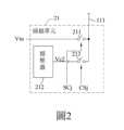
該掃描裝置2包括多個掃描單元21,及一掃描控制單元22。該掃描控制單元22產生多個掃描信號SC1~SCj及多個箝制信號CS1~CSj。該等掃描單元21各自接收一輸入電壓Vin,且分別電連接該等掃描線111,並各自電連接該掃描控制單元22以接收該等掃描信號SC1~SCj中的一對應者及該等箝制信號CS1~CSj中的一對應者。每一掃描單元21根據該等掃描信號SC1~SCj中的該對應者決定是否輸出該輸入電壓Vin,並根據該等箝制信號CS1~CSj中的該對應者決定是否輸出一第二箝制電壓Vc2。每一掃描單元21將該輸入電壓Vin與該第二箝制電壓Vc2的其中之一輸出至該等掃描線111中的一對應掃描線111。需補充說明的是,該第二箝制電壓Vc2是用來改善習知LED顯示器的鬼影現象及耦合問題,此為本領域具通常知識者所熟知,為求簡潔起見,於此不贅述。在本實施例中,每一掃描單元21包括一掃描開關211、一穩壓器212,及一箝制開關213,且每一掃描單元21的細部電路連接關係相同,故於圖2中,為避免圖示雜亂僅繪出第j個掃描單元21進行示意,說明第j個掃描單元21的細部電路連接關係。Thescanning device 2 includes a plurality ofscanning units 21 and ascanning control unit 22 . Thescan control unit 22 generates a plurality of scan signals SC1 ˜ SCj and a plurality of clamping signals CS1 ˜ CSj. Thescanning units 21 each receive an input voltage Vin, are electrically connected to thescanning lines 111, and are electrically connected to thescanning control unit 22 to receive a corresponding one of the scanning signals SC1˜SCj and the clamping signals. One-to-one counterparts in CS1~CSj. Eachscanning unit 21 determines whether to output the input voltage Vin according to the corresponding one of the scanning signals SC1-SCj, and determines whether to output a second clamping voltage Vc2 according to the corresponding one of the clamping signals CS1-CSj. Eachscanning unit 21 outputs one of the input voltage Vin and the second clamping voltage Vc2 to acorresponding scanning line 111 of thescanning lines 111 . It should be added that the second clamping voltage Vc2 is used to improve the ghost phenomenon and the coupling problem of conventional LED displays, which are well known to those skilled in the art, and for the sake of brevity, details are not repeated here. In this embodiment, eachscanning unit 21 includes ascanning switch 211, avoltage regulator 212, and aclamping switch 213, and the detailed circuit connections of eachscanning unit 21 are the same, so in FIG. 2, in order to avoid The diagram is messy and only thejth scanning unit 21 is drawn for schematic illustration, and the detailed circuit connection relationship of thejth scanning unit 21 is explained.

該掃描開關211具有一用於接收該輸入電壓Vin的第一端,及一電連接該等掃描線111中的該對應掃描線111的第二端。該掃描開關211受該掃描信號SCj(即,該等掃描信號中的該對應者)控制而導通或不導通,並於導通時將該輸入電壓Vin經由其該第二端輸出至該對應掃描線111。Thescan switch 211 has a first end for receiving the input voltage Vin, and a second end electrically connected to thecorresponding scan line 111 of thescan lines 111 . Thescan switch 211 is controlled by the scan signal SCj (that is, the corresponding one of the scan signals) to be turned on or not, and when turned on, outputs the input voltage Vin to the corresponding scan line through the second terminal thereof. 111.

該穩壓器212產生該第二箝制電壓Vc2。Thevoltage regulator 212 generates the second clamping voltage Vc2.

該箝制開關213具有一電連接該穩壓器212以接收該第二箝制電壓Vc2的第一端,及一電連接該掃描開關211之該第二端的第二端。該箝制開關213受該箝制信號CSj(即,該等箝制信號中的該對應者)控制而導通或不導通,並於導通時將該第二箝制電壓Vc2經由該掃描開關211之該第二端輸出至該對應掃描線111。該箝制開關213的導通時間與該掃描開關211的導通時間不同。Theclamp switch 213 has a first terminal electrically connected to theregulator 212 to receive the second clamp voltage Vc2 , and a second terminal electrically connected to the second terminal of thescan switch 211 . Theclamping switch 213 is controlled by the clamping signal CSj (that is, the corresponding one of the clamping signals) to conduct or not conduct, and when conducting, the second clamping voltage Vc2 passes through the second end of thescan switch 211 output to thecorresponding scan line 111 . The turn-on time of theclamp switch 213 is different from the turn-on time of thescan switch 211 .

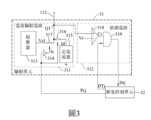
該資料裝置3包括多個驅動單元31及一脈寬控制單元32。在本實施例中,每一驅動單元31包括一電流驅動電路311及一偵測電路312,且每一驅動單元31的細部電路連接關係相同,故於圖3中,為避免圖示雜亂僅繪出第j個驅動單元31進行示意,說明第j個驅動單元31的細部電路連接關係。Thedata device 3 includes a plurality ofdriving units 31 and a pulsewidth control unit 32 . In this embodiment, eachdrive unit 31 includes acurrent drive circuit 311 and adetection circuit 312, and the detailed circuit connections of eachdrive unit 31 are the same, so in FIG. Thejth driving unit 31 is shown for illustration, and the detailed circuit connection relationship of thejth driving unit 31 is explained.

該電流驅動電路311具有一電連接該等資料線112中的一對應資料線112的輸出端Q1,且受一脈寬控制信號Pcj控制而於該輸出端Q1產生並輸出一驅動電流Id與一第一箝制電壓Vc1的其中之一至該對應資料線112。在本實施例中,該電流驅動電路311包括一穩壓器313、一反相器314、一定電流器315,及第一與第二開關316、317。Thecurrent driving circuit 311 has an output terminal Q1 electrically connected to acorresponding data line 112 among thedata lines 112, and is controlled by a pulse width control signal Pcj to generate and output a driving current Id and a driving current Id at the output terminal Q1. One of the first clamping voltages Vc1 is applied to thecorresponding data line 112 . In this embodiment, thecurrent driving circuit 311 includes avoltage regulator 313 , aninverter 314 , a constantcurrent regulator 315 , and first andsecond switches 316 , 317 .

該穩壓器313產生該第一箝制電壓Vc1。該定電流器315產生該驅動電流Id。Theregulator 313 generates the first clamping voltage Vc1. The constantcurrent device 315 generates the driving current Id.

該反相器314接收該脈寬控制信號Pcj,並根據該脈寬控制信號Pcj產生一反相信號Is。Theinverter 314 receives the pulse width control signal Pcj, and generates an inverted signal Is according to the pulse width control signal Pcj.

該第一開關316具有一電連接該電流驅動電路311的該輸出端Q1的第一端,及一電連接該定電流器315以接收該驅動電流Id的第二端。該第一開關316受該脈寬控制信號Pcj控制而導通或不導通,並於導通時將該驅動電流Id輸出至該對應資料線112。Thefirst switch 316 has a first end electrically connected to the output end Q1 of thecurrent driving circuit 311 , and a second end electrically connected to the constantcurrent device 315 for receiving the driving current Id. Thefirst switch 316 is controlled by the pulse width control signal Pcj to be turned on or off, and outputs the driving current Id to thecorresponding data line 112 when turned on.

該第二開關317具有一電連接該穩壓器313以接收該第一箝制電壓Vc1的第一端,及一電連接該電流驅動電路311的該輸出端Q1的第二端。該第二開關317受該反相信號Is控制而導通或不導通,並於導通時將該第一箝制電壓Vc1輸出至該對應資料線112。Thesecond switch 317 has a first end electrically connected to thevoltage regulator 313 to receive the first clamping voltage Vc1 , and a second end electrically connected to the output end Q1 of thecurrent driving circuit 311 . Thesecond switch 317 is controlled by the inverse signal Is to be turned on or off, and outputs the first clamping voltage Vc1 to thecorresponding data line 112 when turned on.

該偵測電路312接收一偵測時序信號DTj,並電連接該電流驅動電路311的該輸出端Q1以偵測該輸出端Q1的電壓,且根據該輸出端Q1的電壓與該偵測時序信號DTj,產生一指示該對應資料線112是否異常的偵測結果。詳細來說,當該對應資料線112所電連接之每一LED113未短路時,該輸出端Q1的電壓相關於該第一箝制電壓Vc1及該驅動電流Id,該對應資料線112處於正常狀態;當該對應資料線112所電連接之該等LED113中的一者短路時,該輸出端Q1的電壓相關於該等LED113中的該者所對應的該掃描單元21所輸出的該輸入電壓Vin及該第二箝制電壓Vc2,使得該輸出端Q1的電壓會於短時間異常偏高,造成該對應資料線112處於異常狀態。在本實施例中,該偵測電路312包括一比較器318,及一邏輯閘319。Thedetection circuit 312 receives a detection timing signal DTj, and is electrically connected to the output terminal Q1 of thecurrent driving circuit 311 to detect the voltage of the output terminal Q1, and according to the voltage of the output terminal Q1 and the detection timing signal DTj, generating a detection result indicating whether thecorresponding data line 112 is abnormal. Specifically, when eachLED 113 electrically connected to thecorresponding data line 112 is not short-circuited, the voltage of the output terminal Q1 is related to the first clamping voltage Vc1 and the driving current Id, and thecorresponding data line 112 is in a normal state; When one of theLEDs 113 electrically connected to thecorresponding data line 112 is short-circuited, the voltage of the output terminal Q1 is related to the input voltage Vin output by thescanning unit 21 corresponding to theLED 113 and The second clamping voltage Vc2 makes the voltage of the output terminal Q1 abnormally high in a short time, causing thecorresponding data line 112 to be in an abnormal state. In this embodiment, thedetection circuit 312 includes acomparator 318 and alogic gate 319 .

該比較器318具有一電連接該電流驅動電路311的該輸出端Q1以偵測該輸出端Q1的電壓的第一輸入端、一接收一預定參考電壓Vr的第二輸入端,及一提供該輸出端Q1的電壓及該預定參考電壓Vr間之一比較之一比較結果Cr的輸出端。Thecomparator 318 has a first input terminal electrically connected to the output terminal Q1 of thecurrent driving circuit 311 to detect the voltage of the output terminal Q1, a second input terminal receiving a predetermined reference voltage Vr, and a supply terminal for providing the An output terminal of a comparison result Cr of a comparison between the voltage of the output terminal Q1 and the predetermined reference voltage Vr.

該邏輯閘319具有一電連接該比較器318以接收該比較結果Cr的第一輸入端、一接收該偵測時序信號DTj的第二輸入端,及一輸出端。該邏輯閘319根據該比較結果Cr與該偵測時序信號DTj於其該輸出端產生該偵測結果Drj。在本實施例中,該邏輯閘319為一及閘,但不限於此。Thelogic gate 319 has a first input end electrically connected to thecomparator 318 for receiving the comparison result Cr, a second input end for receiving the detection timing signal DTj, and an output end. Thelogic gate 319 generates the detection result Drj at its output end according to the comparison result Cr and the detection timing signal DTj. In this embodiment, thelogic gate 319 is an AND gate, but it is not limited thereto.

該脈寬控制單元32電連接該掃描控制單元22,及該等驅動單元31的該等電流驅動電路311與該等偵測電路312,產生並輸出該等電流驅動電路311分別所需的該等脈寬控制信號Pc1~Pcj及該等偵測電路312分別所需的該等偵測時序信號DT1~DTj,且接收來自該等偵測電路312的該等偵測結果Dr1~Drj並輸出至該掃描控制單元22。在本實施例中,該等脈寬控制信號Pc1~Pcj相同,該等偵測時序信號DT1~DTj相同。The pulsewidth control unit 32 is electrically connected to thescanning control unit 22, thecurrent drive circuits 311 and thedetection circuits 312 of thedrive units 31, and generates and outputs thecurrent drive circuits 311 required respectively. The pulse width control signals Pc1~Pcj and the detection timing signals DT1~DTj required by thedetection circuits 312 respectively, and receive the detection results Dr1~Drj from thedetection circuits 312 and output them to theScan control unit 22 . In this embodiment, the pulse width control signals Pc1 ˜ Pcj are the same, and the detection timing signals DT1 ˜ DTj are the same.

參閱圖4,其為一時序圖,以下舉該第一實施例之該掃描裝置2包括四個掃描單元21,該掃描控制單元22產生四個掃描信號SC1~SC4及四個箝制信號CS1~CS4為例,但不限於此,說明該四個掃描信號SC1~SC4、該四個箝制信號CS1~CS4、該脈寬控制信號Pcj,及該偵測時序信號DTj對於時間的變化。同時,說明每一LED113未短路時該輸出端Q1的電壓NVQ1,並舉該LED陣列11的第二行第二列的LED113發生短路為例,但不限於此,說明該第二行第二列的該LED113發生短路時,對應的該輸出端Q1的電壓SVQ1與第二個掃描單元21之該掃描開關211的該第二端的電壓Vsw2。在本實施例中,該輸出端Q1的電壓NVQ1的最小電壓值為對應的LED113電壓減LED的導通電壓,該輸出端Q1的電壓NVQ1的最大電壓值為該第一箝制電壓Vc1。Referring to FIG. 4, which is a timing diagram, thescanning device 2 of the first embodiment includes fourscanning units 21, and thescanning control unit 22 generates four scanning signals SC1~SC4 and four clamping signals CS1~CS4. As an example, but not limited thereto, changes of the four scan signals SC1 - SC4 , the four clamping signals CS1 - CS4 , the pulse width control signal Pcj, and the detection timing signal DTj with respect to time are described. At the same time, the voltage NVQ1 of the output terminal Q1 when eachLED 113 is not short-circuited is described, and theLED 113 in the second row and second column of theLED array 11 is short-circuited as an example, but not limited thereto, and the second row and the second column are described. When theLED 113 is short-circuited, the voltage SVQ1 of the output terminal Q1 corresponds to the voltage Vsw2 of the second terminal of thescanning switch 211 of thesecond scanning unit 21 . In this embodiment, the minimum voltage value of the voltage NVQ1 at the output terminal Q1 is the corresponding voltage of theLED 113 minus the turn-on voltage of the LED, and the maximum voltage value of the voltage NVQ1 at the output terminal Q1 is the first clamping voltage Vc1.

詳細來說,每一掃描單元21的一掃描週期T包括一掃描區間Si及一箝制區間Ci。每一LED113未短路時,在每一掃描單元21的該掃描週期T中,該掃描信號SCj與該箝制信號CSj互補(即,該等掃描信號SC1~SC4分別與該等箝制信號CS1~CS4互補)。於該掃描區間Si,該掃描信號SCj(即,該等掃描信號SC1~SC4中的一對應者)具有一導通準位(即,邏輯「1」)。於該箝制區間Ci,該掃描信號SCj具有一不導通準位(即,邏輯「0」)。更進一步來說,相鄰二個掃描單元21中,前一個掃描單元21的該掃描信號的該導通準位的一結束點,對應下一個掃描單元21的該掃描信號的該導通準位的一起始點。舉例來說,第一個掃描單元21的該掃描信號SC1的該導通準位的該結束點,對應第二個掃描單元21的該掃描信號SC2的該導通準位的該起始點。在每一掃描單元21的該掃描週期T中,該偵測時序信號DTj具有四個偵測準位(即,邏輯「1」)。該四個偵測準位分別對應該四個掃描單元21的該等掃描區間Si。每一偵測準位的持續時間相同並小於每一掃描區間Si。進一步參閱圖4與圖5,說明該偵測時序信號DTj的每一偵測準位的持續時間隨該預定參考電壓Vr的改變而變化。In detail, a scanning period T of each scanningunit 21 includes a scanning interval Si and a clamping interval Ci. When eachLED 113 is not short-circuited, in the scanning period T of each scanningunit 21, the scanning signal SCj is complementary to the clamping signal CSj (that is, the scanning signals SC1~SC4 are complementary to the clamping signals CS1~CS4 respectively ). In the scan interval Si, the scan signal SCj (ie, a corresponding one of the scan signals SC1 ˜ SC4 ) has a conduction level (ie, logic “1”). In the clamping interval Ci, the scan signal SCj has a non-conduction level (ie, logic “0”). Furthermore, in twoadjacent scan units 21, an end point of the conduction level of the scan signal of theprevious scan unit 21 corresponds to the conduction level of the scan signal of thenext scan unit 21. starting point. For example, the end point of the conduction level of the scan signal SC1 of thefirst scan unit 21 corresponds to the start point of the conduction level of the scan signal SC2 of thesecond scan unit 21 . In the scan period T of eachscan unit 21 , the detection timing signal DTj has four detection levels (ie, logic “1”). The four detection levels correspond to the scanning intervals Si of the fourscanning units 21 respectively. The duration of each detection level is the same and shorter than each scanning interval Si. Further referring to FIG. 4 and FIG. 5 , it is illustrated that the duration of each detection level of the detection timing signal DTj varies with the change of the predetermined reference voltage Vr.

在此情況下,當任一資料線112所電連接之任一LED113發生短路,且對應的該偵測時序信號DTj具有該偵測準位時,對應的該邏輯閘319產生的該偵測結果Drj具有一高邏輯準位「1」,以指示該對應資料線112異常。以下舉該第二行第二列的該LED113發生短路為例進行詳細說明。當該第二行第二列的該LED113發生短路,對應的該輸出端Q1的電壓會隨對應的該掃描單元21之該掃描開關211的該第二端的電壓的改變而變化,因此當該掃描信號SC2具有該導通準位時,對應的該輸出端Q1的電壓受該輸入電壓Vin影響而於短時間被異常拉高(如圖4、圖5之該輸出端Q1的電壓SVQ1所示),如此一來,對應該LED陣列11的第二列的該驅動單元31的該比較單元318根據該輸出端Q1的電壓SVQ1及該預定參考電壓Vr所產生的該比較結果Cr具有該高邏輯準位,以致於該偵測時序信號DT2具有該偵測準位時,對應的該驅動單元31的該邏輯閘319根據該比較結果Cr與該偵測時序信號DT2所產生的該偵測結果Dr2具有該高邏輯準位,進而該掃描控制單元22可據以得知該對應資料線112發生異常。In this case, when anyLED 113 electrically connected to anydata line 112 is short-circuited and the corresponding detection timing signal DTj has the detection level, the detection result generated by the correspondinglogic gate 319 Drj has a high logic level "1", indicating that the correspondingdata line 112 is abnormal. The short circuit of theLED 113 in the second row and the second column is taken as an example to describe in detail below. When the LED113 in the second row and second column is short-circuited, the voltage of the corresponding output terminal Q1 will change with the voltage of the second terminal of thescanning switch 211 of thecorresponding scanning unit 21, so when the scanning When the signal SC2 has the conduction level, the voltage of the corresponding output terminal Q1 is affected by the input voltage Vin and is abnormally pulled up in a short time (as shown by the voltage SVQ1 of the output terminal Q1 in Figure 4 and Figure 5 ) In this way, the comparison result Cr generated by thecomparison unit 318 of the drivingunit 31 corresponding to the second column of theLED array 11 according to the voltage SVQ1 of the output terminal Q1 and the predetermined reference voltage Vr has the high logic level, so that when the detection timing signal DT2 has the detection level, thelogic gate 319 of thecorresponding driving unit 31 generates the detection result Dr2 according to the comparison result Cr and the detection timing signal DT2 With the high logic level, thescan control unit 22 can know that the correspondingdata line 112 is abnormal.

進一步參閱圖6,於每一驅動單元31中,當該等偵測結果Dr1~Drj中的一者指示該對應資料線112異常時,該掃描控制單元22根據該等偵測結果Dr1~Drj調整該等箝制信號CS1~CSj中對應當前行掃的該箝制信號。以下繼續以該偵測結果Dr2具有該高邏輯準位且該顯示裝置1當前掃描至第二行掃進行說明。當該等偵測結果Dr1~Drj中的該偵測結果Dr2具有該高邏輯準位時,該掃描控制單元22根據該偵測結果Dr2調整該等箝制信號CS1~CSj中對應當前行掃的該箝制信號CS2,以致於當前行掃的該掃描區間Si,該箝制信號CS2維持在該不導通準位,於該箝制區間Ci,該箝制信號CS2於一箝制導通時間t1具有該導通準位,該箝制導通時間t1位於對應的該箝制區間Ci的一初始時段。在本實施例中,該箝制導通時間t1的一起始點與該掃描信號SC2的該導通準位的該結束點相間隔,但不限於此。在其他實施例中,該掃描信號SC2的該導通準位的該結束點可作為該箝制導通時間t1的該起始點。此外,若該偵測結果Dr2具有該高邏輯準位且該顯示裝置1當前掃描至第三行掃,則該掃描控制單元22根據該偵測結果Dr2調整對應當前行掃的該箝制信號CS3。如此一來,於該掃描控制單元22將該箝制信號CS2調整後,對應的該輸出端Q1的電壓及對應的該掃描單元21之該掃描開關211的該第二端的電壓分別變為如圖6的電壓SVQ1’、電壓Vsw2’所示。於對應的該掃描單元21之每一掃描週期T的一箝制時段Ct,由於對應的該LED113短路,及該掃描信號SC2與該箝制信號CS2具有該不導通準位,因此該輸出端Q1的電壓SVQ1’近似每一LED113未短路時該輸出端Q1的電壓NVQ1,且該掃描開關211的該第二端的電壓Vsw2’受對應的該輸出端Q1的電壓影響而近似每一LED113未短路時該輸出端Q1的電壓NVQ1。如此一來,該掃描開關211的該第二端的電壓Vsw2’不會受該箝制電壓Vc箝制進而無法箝制對應的該資料線112的電壓,以致對應的該資料線112的多個LED113不會因對應的該LED113短路而發生恆亮或恆暗,進而可避免短路毛毛蟲現象。Further referring to FIG. 6 , in each drivingunit 31, when one of the detection results Dr1~Drj indicates that the correspondingdata line 112 is abnormal, thescan control unit 22 adjusts according to the detection results Dr1~Drj Among the clamping signals CS1 ˜ CSj , the clamping signal corresponding to the current horizontal scan. The following continues to illustrate that the detection result Dr2 has the high logic level and thedisplay device 1 is currently scanning to the second row. When the detection result Dr2 among the detection results Dr1~Drj has the high logic level, thescan control unit 22 adjusts the clamping signals CS1~CSj corresponding to the current line scan according to the detection result Dr2. Clamping signal CS2, so that in the scanning interval Si of the current line scan, the clamping signal CS2 maintains the non-conduction level, and in the clamping interval Ci, the clamping signal CS2 has the conduction level during a clamping conduction time t1, the The clamping on-time t1 is located at an initial period corresponding to the clamping interval Ci. In this embodiment, a start point of the clamped conduction time t1 is spaced from the end point of the conduction level of the scan signal SC2 , but it is not limited thereto. In other embodiments, the end point of the conduction level of the scan signal SC2 can be used as the start point of the clamped conduction time t1. In addition, if the detection result Dr2 has the high logic level and thedisplay device 1 is currently scanning to the third row, thescan control unit 22 adjusts the clamping signal CS3 corresponding to the current row according to the detection result Dr2. In this way, after thescan control unit 22 adjusts the clamping signal CS2, the corresponding voltage of the output terminal Q1 and the corresponding voltage of the second terminal of thescan switch 211 of thescan unit 21 become respectively as shown in FIG. 6 The voltage SVQ1 ', the voltage Vsw2' is shown. During a clamping period Ct of each scanning cycle T of thecorresponding scanning unit 21, since the corresponding LED113 is short-circuited, and the scanning signal SC2 and the clamping signal CS2 have the non-conduction level, the voltage of the output terminal Q1 SVQ1 'approximates the voltage NVQ1 of the output terminal Q1 when each LED113 is not short-circuited, and the voltage Vsw2' of the second terminal of thescan switch 211 is affected by the corresponding voltage of the output terminal Q1 and approximates when each LED113 is not short-circuited The voltage NVQ1 at the output terminal Q1. In this way, the voltage Vsw2' of the second terminal of thescan switch 211 will not be clamped by the clamping voltage Vc and cannot clamp the voltage of the correspondingdata line 112, so that the plurality ofLEDs 113 corresponding to thedata line 112 will not be clamped by the clamping voltage Vc. Correspondingly, theLED 113 is short-circuited to produce constant brightness or constant darkness, thereby avoiding the phenomenon of short-circuited caterpillars.

<第二實施例><Second embodiment>

參閱圖7,本發明驅動裝置的一第二實施例為該第一實施例的修改,二者不同之處在於:以一定電流器315’ 及一第一開關316’分別取代圖3的該定電流器315 及該第一開關316。Referring to Fig. 7, a second embodiment of the driving device of the present invention is a modification of the first embodiment, the difference between the two is: the fixed current device 315' and a first switch 316' are respectively replaced in Fig. 3 Thecurrent generator 315 and thefirst switch 316 .

該定電流器315’電連接該偵測電路312之該比較器318的該第一輸入端,且產生該驅動電流Id。該第一開關316’具有一電連接該電流驅動電路311的該輸出端Q1的第一端,及一電連接該比較器318的該第一輸入端與該定電流器315’並接收該驅動電流Id的第二端。該第一開關316’受該脈寬控制信號Pcj控制而導通或不導通。當該第一開關316’導通時,該第一開關316’將該驅動電流Id輸出至該對應資料線112,且該偵測電路312經由該第一開關316’偵測該電流驅動電路311的該輸出端Q1的電壓,以判斷對應的資料線112是否異常。The constant current device 315' is electrically connected to the first input terminal of thecomparator 318 of thedetection circuit 312, and generates the driving current Id. The first switch 316' has a first end electrically connected to the output end Q1 of thecurrent drive circuit 311, and a first end electrically connected to the first input end of thecomparator 318 and the constant current device 315' and receives the drive The second terminal of the current Id. The first switch 316' is controlled by the pulse width control signal Pcj to conduct or not conduct. When the first switch 316' is turned on, the first switch 316' outputs the driving current Id to the correspondingdata line 112, and thedetection circuit 312 detects thecurrent driving circuit 311 through the first switch 316'. The voltage of the output terminal Q1 is used to determine whether the correspondingdata line 112 is abnormal.

需說明的是,該第二實施例具有相似於上述第一實施例中所述的運作,並能達成如上述第一實施例中所述的所有功效,為求簡潔起見,於此不再重複說明。It should be noted that the second embodiment has operations similar to those described in the above-mentioned first embodiment, and can achieve all the functions described in the above-mentioned first embodiment. For the sake of brevity, no further Repeat instructions.

需注意的是,如圖1所示,該掃描控制單元22是根據來自該脈寬控制單元32的該等偵測結果Dr1~Drj,決定是否調整該等箝制信號CS1~CSj中對應當前行掃的該箝制信號,但不限於此。該掃描控制單元22也可根據來自該等驅動單元31的該等偵測結果、或來自多個該資料裝置3中的最後一個資料裝置3的該等偵測結果、或來自每一資料裝置3的該等偵測結果,或經由至少一該資料裝置3及一控制裝置所接收到的該等偵測結果,決定是否調整該等箝制信號CS1~CSj中對應當前行掃的該箝制信號。It should be noted that, as shown in FIG. 1 , thescan control unit 22 determines whether to adjust the clamping signals CS1 to CSj corresponding to the current line scan according to the detection results Dr1 to Drj from the pulsewidth control unit 32. of the clamping signal, but not limited thereto. Thescan control unit 22 can also be based on the detection results from thedrive units 31, or from the detection results of thelast data device 3 in a plurality of thedata devices 3, or from eachdata device 3 The detection results, or the detection results received through at least onedata device 3 and a control device, determine whether to adjust the clamping signal corresponding to the current line scan among the clamping signals CS1~CSj.

詳細來說,參閱圖8至圖17,其說明該等偵測結果經不同傳輸路徑傳輸至對應的該掃描控制單元22的各種實施態樣。In detail, refer to FIG. 8 to FIG. 17 , which illustrate various implementation aspects in which the detection results are transmitted to the correspondingscanning control unit 22 through different transmission paths.

參閱圖8,圖8與圖1的差異在於,該脈寬控制單元32並未電連接該掃描控制單元22,而是該等驅動單元31之該等偵測電路312(圖未示)電連接該掃描控制單元22,如此一來,該等驅動單元31之該等偵測電路312可分別將該等偵測結果Dr1~Drj直接傳輸至該掃描控制單元22,以決定是否調整該等箝制信號CS1~CSj中對應當前行掃的該箝制信號。換言之,該等偵測電路312不需將該等偵測結果Dr1~Drj先傳輸至該脈寬控制單元32,再由該脈寬控制單元32傳輸至該掃描控制單元22。Referring to FIG. 8, the difference between FIG. 8 and FIG. 1 is that the pulsewidth control unit 32 is not electrically connected to thescanning control unit 22, but the detection circuits 312 (not shown) of the drivingunits 31 are electrically connected Thescan control unit 22, so that thedetection circuits 312 of thedrive units 31 can directly transmit the detection results Dr1~Drj to thescan control unit 22 respectively, so as to determine whether to adjust the clamping signals CS1~CSj corresponds to the clamping signal of the current line scan. In other words, thedetection circuits 312 do not need to transmit the detection results Dr1 ˜ Drj to the pulsewidth control unit 32 first, and then the pulsewidth control unit 32 transmits them to thescan control unit 22 .

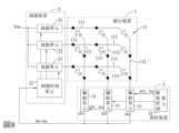
參閱圖9,圖9與圖1相似,二者差異在於圖9中,該掃描式顯示器是包含二個該顯示裝置1及二個該資料裝置3。該等顯示裝置1以矩陣排列方式電連接。該等資料裝置3的該等脈寬控制單元32依序串接,每一資料裝置3電連接所對應的該顯示裝置1,且最後一個資料裝置3的該脈寬控制單元32電連接該掃描控制單元22。該最後一個資料裝置3的該脈寬控制單元32接收第一個資料裝置3的該脈寬控制單元32所產生的該等偵測結果Dr1~Drj(即,該最後一個資料裝置3接收該等資料裝置3中其餘每一者所產生的該等偵測結果),並將所接收到的該等偵測結果Dr1~Drj及其自身所產生的該等偵測結果Dr1’~Drj’傳輸至該掃描控制單元22。Referring to FIG. 9 , FIG. 9 is similar to FIG. 1 , the difference between them is that in FIG. 9 , the scanning display includes twodisplay devices 1 and twodata devices 3 . Thedisplay devices 1 are electrically connected in a matrix arrangement. The pulsewidth control units 32 of thedata devices 3 are sequentially connected in series, eachdata device 3 is electrically connected to thecorresponding display device 1, and the pulsewidth control unit 32 of thelast data device 3 is electrically connected to thescan control unit 22. The pulsewidth control unit 32 of thelast data device 3 receives the detection results Dr1~Drj generated by the pulsewidth control unit 32 of the first data device 3 (that is, thelast data device 3 receives the detection results Dr1~Drj The detection results generated by each of the remaining data devices 3), and the received detection results Dr1~Drj and the detection results Dr1'~Drj' generated by themselves are transmitted to Thescan control unit 22 .

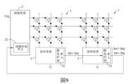
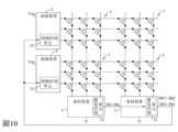
參閱圖10,圖10與圖9相似,二者差異在於圖10中,該掃描式顯示器是包含四個該顯示裝置1及二個該掃描裝置2。每一掃描裝置2電連接所對應的該等顯示裝置1。該最後一個資料裝置3的該脈寬控制單元32電連接該等掃描裝置2的該等掃描控制單元22。該最後一個資料裝置3的該脈寬控制單元32將所接收到的該等偵測結果Dr1~Drj及其自身所產生的該等偵測結果Dr1’~Drj’傳輸至該等掃描裝置2的該等掃描控制單元22。Referring to FIG. 10 , FIG. 10 is similar to FIG. 9 , the difference between them is that in FIG. 10 , the scanning display includes fourdisplay devices 1 and twoscanning devices 2 . Eachscanning device 2 is electrically connected to thecorresponding display devices 1 . The pulsewidth control unit 32 of thelast data device 3 is electrically connected to thescan control units 22 of thescan devices 2 . The pulsewidth control unit 32 of thelast data device 3 transmits the received detection results Dr1~Drj and the detection results Dr1'~Drj' generated by itself to thescanning devices 2. Thescanning control unit 22 .

參閱圖11,圖11與圖10相似,二者差異在於圖11中,該等掃描裝置2的該等掃描控制單元22依序串接。該最後一個資料裝置3的該脈寬控制單元32電連接該等掃描裝置2的第一個掃描裝置2的該掃描控制單元22。該最後一個資料裝置3的該脈寬控制單元32將所接收到的該等偵測結果Dr1~Drj及其自身所產生的該等偵測結果Dr1’~Drj’傳輸至該第一個掃描裝置2的該掃描控制單元22。第i個掃描裝置2的該掃描控制單元22將所接收到的該等偵測結果Dr1~Drj、Dr1’~Drj’傳輸至第i+1個掃描裝置2的該掃描控制單元22,i為正整數,1≦i≦N-1,N為該等掃描裝置2的一總數量。舉例來說,於圖11中,N等於二,該第一個掃描裝置2的該掃描控制單元22將所接收到的該等偵測結果Dr1~Drj、Dr1’~Drj’傳輸至第二個掃描裝置2的該掃描控制單元22。Referring to FIG. 11 , FIG. 11 is similar to FIG. 10 , the difference between the two lies in that in FIG. 11 , thescanning control units 22 of thescanning devices 2 are serially connected. The pulsewidth control unit 32 of thelast data device 3 is electrically connected to thescan control unit 22 of thefirst scan device 2 of thescan devices 2 . The pulsewidth control unit 32 of thelast data device 3 transmits the received detection results Dr1~Drj and the detection results Dr1'~Drj' generated by itself to thefirst scanning device 2 of thescan control unit 22. Thescanning control unit 22 of the i-th scanning device 2 transmits the received detection results Dr1-Drj, Dr1'-Drj' to thescanning control unit 22 of the i+1-th scanning device 2, where i is Positive integer, 1≦i≦N-1, N is a total number of thescanning devices 2 . For example, in FIG. 11, N is equal to two, and thescanning control unit 22 of thefirst scanning device 2 transmits the received detection results Dr1~Drj, Dr1'~Drj' to thesecond scanning device 2. Thescanning control unit 22 of thescanning device 2 .

參閱圖12,圖12與圖11相似,二者差異在於圖12中,該等資料裝置3的該等脈寬控制單元32不是依序串接。每一資料裝置3的該脈寬控制單元32電連接該第一個掃描裝置2的該掃描控制單元22。該等資料裝置3的該等脈寬控制單元32將分別所產生的該等偵測結果Dr1~Drj、Dr1’~Drj’傳輸至該第一個掃描裝置2的該掃描控制單元22。Referring to FIG. 12 , FIG. 12 is similar to FIG. 11 , the difference between them is that in FIG. 12 , the pulsewidth control units 32 of thedata devices 3 are not connected in series. The pulsewidth control unit 32 of eachdata device 3 is electrically connected to thescan control unit 22 of thefirst scan device 2 . The pulsewidth control units 32 of thedata devices 3 transmit the detection results Dr1~Drj, Dr1'~Drj' generated respectively to thescan control unit 22 of thefirst scan device 2.

參閱圖13,圖13與圖9相似,二者差異在於圖13中,該等資料裝置3的該等脈寬控制單元32不是依序串接。每一資料裝置3的該脈寬控制單元32電連接該掃描裝置2的該掃描控制單元22及所對應的該顯示裝置1。該等資料裝置3的該等脈寬控制單元32將分別所產生的該等偵測結果Dr1~Drj、Dr1’~Drj’傳輸至該掃描控制單元22。Referring to FIG. 13 , FIG. 13 is similar to FIG. 9 , the difference between them is that in FIG. 13 , the pulsewidth control units 32 of thedata devices 3 are not connected in series. The pulsewidth control unit 32 of eachdata device 3 is electrically connected to thescan control unit 22 of thescan device 2 and thecorresponding display device 1 . The pulsewidth control units 32 of thedata devices 3 transmit the detection results Dr1~Drj, Dr1'~Drj' generated respectively to thescan control unit 22.

參閱圖14,圖14與圖13相似,二者差異在於圖14中,該掃描式顯示器是包含四個該顯示裝置1及二個該掃描裝置2。每一掃描裝置2電連接所對應的該等顯示裝置1。每一資料裝置3的該脈寬控制單元32電連接該等掃描裝置2的該等掃描控制單元22及所對應的該等顯示裝置1。該等資料裝置3的該等脈寬控制單元32將分別所產生的該等偵測結果Dr1~Drj、Dr1’~Drj’傳輸至該等掃描控制單元22。Referring to FIG. 14 , FIG. 14 is similar to FIG. 13 , the difference between them is that in FIG. 14 , the scanning display includes fourdisplay devices 1 and twoscanning devices 2 . Eachscanning device 2 is electrically connected to thecorresponding display devices 1 . The pulsewidth control unit 32 of eachdata device 3 is electrically connected to thescan control units 22 of thescan devices 2 and thecorresponding display devices 1 . The pulsewidth control units 32 of thedata devices 3 transmit the detection results Dr1~Drj, Dr1'~Drj' generated respectively to thescan control units 22.

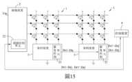
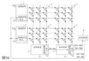
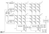
參閱圖15、16、17,圖15~17分別與圖9~11相似,差異在於圖15、16、17中,該掃描式顯示器還包含一控制裝置4。Referring to Figures 15, 16, and 17, Figures 15 to 17 are similar to Figures 9 to 11, the difference lies in Figures 15, 16, and 17, the scanning display also includes acontrol device 4.

於圖15中,該控制裝置4電連接在該最後一個資料裝置3的該脈寬控制單元32及該掃描裝置2的該掃描控制單元22之間。該最後一個資料裝置3的該脈寬控制單元32是將所接收到的該等偵測結果Dr1~Drj及其自身所產生的該等偵測結果Dr1’~Drj’經由該控制裝置4傳輸至該掃描控制單元22。In FIG. 15 , thecontrol device 4 is electrically connected between the pulsewidth control unit 32 of thelast data device 3 and thescan control unit 22 of thescan device 2 . The pulsewidth control unit 32 of thelast data device 3 transmits the received detection results Dr1~Drj and the detection results Dr1'~Drj' generated by itself via thecontrol device 4 to Thescan control unit 22 .

於圖16中,該控制裝置4電連接該最後一個資料裝置3的該脈寬控制單元32及該等掃描裝置2的該等掃描控制單元22。該最後一個資料裝置3的該脈寬控制單元32是將該等偵測結果Dr1~Drj、Dr1’~Drj’經由該控制裝置4傳輸至該等掃描控制單元22。In FIG. 16 , thecontrol device 4 is electrically connected to the pulsewidth control unit 32 of thelast data device 3 and thescan control units 22 of thescan devices 2 . The pulsewidth control unit 32 of thelast data device 3 transmits the detection results Dr1~Drj, Dr1'~Drj' to thescan control unit 22 via thecontrol device 4.

於圖17中,該控制裝置4電連接在該最後一個資料裝置3的該脈寬控制單元32及該第一個掃描裝置2的該掃描控制單元22之間。該最後一個資料裝置3的該脈寬控制單元32是將該等偵測結果Dr1~Drj、Dr1’~Drj’經由該控制裝置4傳輸至該第一個掃描裝置2的該掃描控制單元22。In FIG. 17 , thecontrol device 4 is electrically connected between the pulsewidth control unit 32 of thelast data device 3 and thescan control unit 22 of thefirst scan device 2 . The pulsewidth control unit 32 of thelast data device 3 transmits the detection results Dr1~Drj, Dr1'~Drj' to thescan control unit 22 of thefirst scan device 2 via thecontrol device 4.

需說明的是,該控制裝置4可以操作來產生該掃描裝置2及該資料裝置3正常顯示時所需的相關參數設定及灰階資料。由於該控制裝置4的技術已為通常知識者所熟知,且其並非本發明的特徵,故在此省略其細節不再贅述。It should be noted that thecontrol device 4 can be operated to generate relevant parameter settings and grayscale data required for normal display of thescanning device 2 and thedata device 3 . Since the technology of thecontrol device 4 is well known to those skilled in the art, and it is not a feature of the present invention, its details are omitted here for brevity.

綜上所述,本發明具短路偵測功能的掃描式顯示器利用每一偵測電路312對每一電流驅動電路311的該輸出端Q1進行偵測,並將該偵測結果Drj傳輸至對應的掃描控制單元22,以致對應的掃描控制單元22可得知該對應資料線112是否因有LED113短路而異常,並據以調整對應當前行掃的該箝制信號CSj,如此一來,對應的該掃描開關211的該第二端的電壓Vsw2’不會受該箝制電壓Vc箝制進而無法箝制對應的該資料線112的電壓,以致對應的該資料線112的多個LED113不會因對應的該LED113短路而發生恆亮或恆暗,進而可避免發生短路毛毛蟲現象。此外,該資料裝置3會將該等偵測結果Dr1~Drj傳至每一掃描裝置2或該控制裝置4,以通報每一掃描裝置2或該控制裝置4,使其得知是否有資料線112發生異常,進而該資料裝置3具有通報之功效。In summary, the scanning display with short-circuit detection function of the present invention uses eachdetection circuit 312 to detect the output terminal Q1 of eachcurrent drive circuit 311, and transmits the detection result Drj to the corresponding Thescan control unit 22, so that the correspondingscan control unit 22 can know whether the correspondingdata line 112 is abnormal due to the short circuit of theLED 113, and adjust the clamping signal CSj corresponding to the current line scan accordingly. In this way, the corresponding scan The voltage Vsw2' of the second end of theswitch 211 will not be clamped by the clamping voltage Vc and cannot clamp the voltage of the correspondingdata line 112, so that the plurality ofLEDs 113 of the correspondingdata line 112 will not be damaged due to the short circuit of the correspondingLEDs 113. Constant light or constant dark occurs, thereby avoiding short-circuit caterpillar phenomenon. In addition, thedata device 3 will transmit the detection results Dr1~Drj to eachscanning device 2 or thecontrol device 4, so as to notify eachscanning device 2 or thecontrol device 4 to know whether there is adata line 112 is abnormal, and then thedata device 3 has the function of notification.

惟以上所述者,僅為本發明的實施例而已,當不能以此限定本發明實施的範圍,凡是依本發明申請專利範圍及專利說明書內容所作的簡單的等效變化與修飾,皆仍屬本發明專利涵蓋的範圍內。But the above-mentioned ones are only embodiments of the present invention, and should not limit the scope of the present invention. All simple equivalent changes and modifications made according to the patent scope of the present invention and the content of the patent specification are still within the scope of the present invention. Within the scope covered by the patent of the present invention.

1:顯示裝置 11:發光二極體陣列 111:掃描線 112:資料線 113:發光二極體 2:掃描裝置 21:掃描單元 211:掃描開關 212:穩壓器 213:箝制開關 22:掃描控制單元 3:資料裝置 31:驅動單元 311:電流驅動電路 312:偵測電路 313:穩壓器 314:反相器 315、315’:定電流器 316、316’:第一開關 317:第二開關 318:比較器 319:邏輯閘 32:脈寬控制單元 4:控制裝置 Ci:箝制區間 Cr:比較結果 CS1~CSj:箝制信號 Ct:箝制時段 Dr1~Drj:偵測結果 Dr1’~Drj’:偵測結果 DT1~DTj:偵測時序信號 Id:驅動電流 Is:反相信號 NVQ1:輸出端電壓 Pc1~Pcj:脈寬控制信號 Q1:輸出端 Si:掃描區間 SC1~SCj:掃描信號 SVQ1、SVQ1’:輸出端電壓 t1:箝制導通時間 T:掃描週期 Vin:輸入電壓 Vc1:第一箝制電壓 Vc2:第二箝制電壓 Vr:預定參考電壓 Vsw2、Vsw2’:掃描開關第二端的電壓1: Display device 11: Light emitting diode array 111: scan line 112: data line 113: light emitting diode 2: Scanning device 21: Scanning unit 211: Scan switch 212: voltage regulator 213: clamp switch 22: Scan control unit 3: Data device 31: Drive unit 311: Current drive circuit 312: Detection circuit 313:Voltage regulator 314:Inverter 315, 315': constantcurrent device 316, 316': the first switch 317: second switch 318: Comparator 319: logic gate 32: Pulse width control unit 4: Control device Ci: Clamp interval Cr: comparison result CS1~CSj: Clamp signal Ct: Clamp period Dr1~Drj: detection results Dr1’~Drj’: detection results DT1~DTj: detection timing signal Id: drive current Is: Inverted signal NVQ1: output terminal voltage Pc1~Pcj: pulse width control signal Q1: output terminal Si: scan interval SC1~SCj: scan signal SVQ1, SVQ1': output terminal voltage t1: Clamp on time T: scan period Vin: input voltage Vc1: the first clamping voltage Vc2: the second clamping voltage Vr: predetermined reference voltage Vsw2, Vsw2': the voltage of the second terminal of the scan switch

本發明的其他的特徵及功效,將於參照圖式的實施方式中清楚地呈現,其中: 圖1是一電路方塊圖,說明本發明具短路偵測功能的掃描式顯示器之一第一實施例; 圖2是一電路方塊圖,說明該第一實施例的一掃描單元; 圖3是一電路方塊圖,說明該第一實施例的一驅動單元; 圖4是一時序圖,說明該第一實施例的多個掃描信號、多個箝制信號、一偵測時序信號、一脈寬控制信號、一預定參考電壓,及該掃描單元與該驅動單元之輸出端的電壓; 圖5是一時序圖,說明該第一實施例的該偵測時序信號隨該預定參考電壓的變化而改變; 圖6是一時序圖,說明該第一實施例偵測出短路且調整後的該等掃描信號、該等箝制信號,及該掃描單元與該驅動單元之輸出端的電壓; 圖7是一電路方塊圖,說明本發明具短路偵測功能的掃描式顯示器之一驅動單元的一第二實施例;及 圖8至圖17,說明該第一實施例的多個偵測結果經不同傳輸路徑傳輸至對應的掃描控制單元的各種實施態樣。Other features and effects of the present invention will be clearly presented in the implementation manner with reference to the drawings, wherein: 1 is a circuit block diagram illustrating a first embodiment of a scanning display with a short-circuit detection function of the present invention; Fig. 2 is a circuit block diagram illustrating a scanning unit of the first embodiment; Fig. 3 is a circuit block diagram illustrating a driving unit of the first embodiment; FIG. 4 is a timing diagram illustrating a plurality of scanning signals, a plurality of clamping signals, a detection timing signal, a pulse width control signal, a predetermined reference voltage, and the relationship between the scanning unit and the driving unit of the first embodiment. the voltage at the output; FIG. 5 is a timing diagram illustrating that the detection timing signal of the first embodiment changes as the predetermined reference voltage changes; FIG. 6 is a timing diagram illustrating the adjusted scanning signals, clamping signals, and output voltages of the scanning unit and the driving unit after the short circuit is detected in the first embodiment; 7 is a circuit block diagram illustrating a second embodiment of a driving unit of a scanning display with a short-circuit detection function of the present invention; and FIG. 8 to FIG. 17 illustrate various implementation aspects in which multiple detection results of the first embodiment are transmitted to corresponding scanning control units through different transmission paths.

112:資料線112: data line

31:驅動單元31: Drive unit

311:電流驅動電路311: Current drive circuit

312:偵測電路312: Detection circuit

313:穩壓器313:Voltage regulator

314:反相器314: Inverter

315:定電流器315: constant current device

316、317:第一與第二開關316, 317: first and second switches

318:比較器318: Comparator

319:邏輯閘319: logic gate

32:脈寬控制單元32: Pulse width control unit

Cr:比較結果Cr: comparison result

Drj:偵測結果Drj: detection result

DTj:偵測時序信號DTj: detect timing signal

Id:驅動電流Id: drive current

Is:反相信號Is: Inverted signal

Pcj:脈寬控制信號Pcj: pulse width control signal

Q1:輸出端Q1: output terminal

Vc1:第一箝制電壓Vc1: the first clamping voltage

Vr:預定參考電壓Vr: predetermined reference voltage

Claims (23)

Translated fromChinese
一種具短路偵測功能的掃描式顯示器,包含:一顯示裝置,包括一共陽極架構的發光二極體陣列,該發光二極體陣列包括,多條掃描線,彼此沿一行方向設置,多條資料線,彼此沿一列方向垂直設置於該等掃描線,及多個發光二極體,分別對應地設置於由該等掃描線與該等資料線所界定的矩陣間,每一該發光二極體具有一電連接所對應的該掃描線的陽極,及一電連接所對應的該資料線的陰極;及一資料裝置,包括多個驅動單元,每一該驅動單元包括,一電流驅動電路,具有一電連接該等資料線中的一對應資料線的輸出端,且受一脈寬控制信號控制而於該輸出端產生並輸出一驅動電流與一第一箝制電壓的其中之一至該對應資料線,及一偵測電路,接收一偵測時序信號,並偵測該電流驅動電路的該輸出端的電壓,且根據該輸出端的電壓與該偵測時序信號,產生一指示該對應資料線是否異常的偵測結果。A scanning display with a short-circuit detection function, comprising: a display device, including a light-emitting diode array with a common anode structure, the light-emitting diode array includes, a plurality of scanning lines arranged along a row direction, and a plurality of data Lines are arranged perpendicular to the scanning lines along a column direction, and a plurality of light emitting diodes are respectively arranged correspondingly between the matrix defined by the scanning lines and the data lines, each of the light emitting diodes There is an anode electrically connected to the corresponding scanning line, and a cathode electrically connected to the corresponding data line; and a data device, including a plurality of driving units, each of which includes a current driving circuit, having An output end electrically connected to a corresponding data line in the data lines, and controlled by a pulse width control signal to generate and output one of a driving current and a first clamping voltage to the corresponding data line at the output end , and a detection circuit, receiving a detection timing signal, and detecting the voltage of the output terminal of the current driving circuit, and generating a signal indicating whether the corresponding data line is abnormal according to the voltage of the output terminal and the detection timing signal detection results.如請求項1所述的具短路偵測功能的掃描式顯示器,其中,於每一該驅動單元中,該偵測電路包括,一比較器,具有一用來偵測該電流驅動電路的該輸出端的電壓的第一輸入端、一接收一預定參考電壓的第二輸入端,及一提供該輸出端的電壓及該預定參考電壓間之一比較之一比較結果的輸出端,及一邏輯閘,具有一電連接該比較器以接收該比較結果的第一輸入端、一接收該偵測時序信號的第二輸入端,及一輸出端,該邏輯閘根據該比較結果與該偵測時序信號於其該輸出端產生該偵測結果。The scanning display with short-circuit detection function as described in claim 1, wherein, in each of the drive units, the detection circuit includes a comparator with an output for detecting the current drive circuita first input terminal receiving a voltage at the output terminal, a second input terminal receiving a predetermined reference voltage, and an output terminal providing a comparison result of a comparison between the voltage at the output terminal and the predetermined reference voltage, and a logic gate, It has a first input end electrically connected to the comparator to receive the comparison result, a second input end for receiving the detection timing signal, and an output end, and the logic gate is based on the comparison result and the detection timing signal at The output end produces the detection result.如請求項1所述的具短路偵測功能的掃描式顯示器,其中,於每一該驅動單元中,該偵測電路電連接該電流驅動電路的該輸出端以偵測該輸出端的電壓,且該電流驅動電路包括,一穩壓器,產生該第一箝制電壓,一反相器,接收該脈寬控制信號,並根據該脈寬控制信號產生一反相信號,一定電流器,產生該驅動電流,一第一開關,具有一電連接該電流驅動電路的該輸出端的第一端,及一電連接該定電流器以接收該驅動電流的第二端,該第一開關受該脈寬控制信號控制而導通或不導通,並於導通時將該驅動電流輸出至該對應資料線,及一第二開關,具有一電連接該穩壓器以接收該第一箝制電壓的第一端,及一電連接該電流驅動電路的該輸出端的第二端,該第二開關受該反相信號控制而導通或不導通,並於導通時將該第一箝制電壓輸出至該對應資料線。The scanning display with short-circuit detection function as described in claim 1, wherein, in each of the drive units, the detection circuit is electrically connected to the output terminal of the current drive circuit to detect the voltage of the output terminal, and The current drive circuit includes a voltage regulator to generate the first clamping voltage, an inverter to receive the pulse width control signal, and generate an inversion signal according to the pulse width control signal, and a constant current device to generate the drive Current, a first switch, has a first end electrically connected to the output end of the current drive circuit, and a second end electrically connected to the constant current device to receive the drive current, the first switch is controlled by the pulse width signal control to conduct or not conduct, and output the driving current to the corresponding data line when conducting, and a second switch having a first end electrically connected to the regulator to receive the first clamping voltage, and A second terminal electrically connected to the output terminal of the current drive circuit, the second switch is controlled by the anti-phase signal to conduct or not conduct, and when conducting, output the first clamping voltage to the corresponding resourcefeed line.如請求項1所述的具短路偵測功能的掃描式顯示器,其中,於每一該驅動單元中,該電流驅動電路包括,一穩壓器,產生該第一箝制電壓,一反相器,接收該脈寬控制信號,並根據該脈寬控制信號產生一反相信號,一定電流器,電連接該偵測電路,且產生該驅動電流,一第一開關,具有一電連接該電流驅動電路的該輸出端的第一端,及一電連接該偵測電路與該定電流器並接收該驅動電流的第二端,該第一開關受該脈寬控制信號控制而導通或不導通,當該第一開關導通時,該第一開關將該驅動電流輸出至該對應資料線,且該偵測電路經由該第一開關偵測該電流驅動電路的該輸出端的電壓,及一第二開關,具有一電連接該穩壓器以接收該第一箝制電壓的第一端,及一電連接該電流驅動電路的該輸出端的第二端,該第二開關受該反相信號控制而導通或不導通,並於導通時將該第一箝制電壓輸出至該對應資料線。The scanning display with short-circuit detection function as described in claim 1, wherein, in each of the driving units, the current driving circuit includes a voltage regulator for generating the first clamping voltage, an inverter, receiving the pulse width control signal, and generating an antiphase signal according to the pulse width control signal, a certain current device, electrically connected to the detection circuit, and generating the driving current, a first switch, having a current drive circuit electrically connected The first terminal of the output terminal, and a second terminal electrically connected to the detection circuit and the constant current device and receiving the driving current, the first switch is controlled by the pulse width control signal to conduct or not conduct, when the When the first switch is turned on, the first switch outputs the drive current to the corresponding data line, and the detection circuit detects the voltage of the output end of the current drive circuit through the first switch, and a second switch has a first end electrically connected to the regulator to receive the first clamping voltage, and a second end electrically connected to the output end of the current drive circuit, the second switch is controlled by the anti-phase signal to conduct or not conduct , and output the first clamping voltage to the corresponding data line when turned on.如請求項1所述的具短路偵測功能的掃描式顯示器,還包含一掃描裝置,該掃描裝置包括一掃描控制單元,產生多個掃描信號及多個箝制信號,且接收該等偵測結果,並根據該等偵測結果決定是否調整該等箝制信號中對應當前行掃的該箝制信號,及多個掃描單元,各自接收一輸入電壓,且分別電連接該等掃描線,並各自電連接該掃描控制單元以接收該等掃描信號中的一對應者及該等箝制信號中的一對應者,每一該掃描單元根據該等掃描信號中的該對應者決定是否輸出該輸入電壓,並根據該等箝制信號中的該對應者決定是否輸出一第二箝制電壓,每一該掃描單元將該輸入電壓與該第二箝制電壓的其中之一輸出至該等掃描線中的一對應掃描線。The scanning display with short-circuit detection function as described in Claim 1 further includes a scanning device, the scanning device includes a scanning control unit, which generates a plurality of scanning signals and a plurality of clamping signals, and receives the detection results , and based on the detection results it is determined that theWhether to adjust the clamping signal corresponding to the current line scan among the clamping signals, and a plurality of scanning units each receive an input voltage, and are respectively electrically connected to the scanning lines, and are respectively electrically connected to the scanning control unit to receive the scanning A corresponding one of the signals and a corresponding one of the clamping signals, each scanning unit determines whether to output the input voltage according to the corresponding one of the scanning signals, and determines whether to output the input voltage according to the corresponding one of the clamping signals It is determined whether to output a second clamping voltage, and each scanning unit outputs one of the input voltage and the second clamping voltage to a corresponding scanning line among the scanning lines.如請求項5所述的具短路偵測功能的掃描式顯示器,其中,每一該掃描單元包括,一掃描開關,具有一用於接收該輸入電壓的第一端,及一電連接該等掃描線中的該對應掃描線的第二端,該掃描開關受該等掃描信號中的該對應者控制而導通或不導通,並於導通時將該輸入電壓經由其該第二端輸出至該對應掃描線,一穩壓器,產生該第二箝制電壓,及一箝制開關,具有一電連接該穩壓器以接收該第二箝制電壓的第一端,及一電連接該掃描開關之該第二端的第二端,該箝制開關受該等箝制信號中的該對應者控制而導通或不導通,並於導通時將該第二箝制電壓經由該掃描開關之該第二端輸出至該對應掃描線,該箝制開關的導通時間與該掃描開關的導通時間不同。The scanning display with short-circuit detection function as described in claim 5, wherein each scanning unit includes a scanning switch having a first end for receiving the input voltage, and a first terminal electrically connected to the scanning The second end of the corresponding scanning line in the line, the scanning switch is controlled by the corresponding one of the scanning signals to conduct or not conduct, and when conducting, the input voltage is output to the corresponding Scanning line, a voltage regulator to generate the second clamping voltage, and a clamping switch having a first end electrically connected to the voltage regulator to receive the second clamping voltage, and a first terminal electrically connected to the scanning switch The second terminal of the two terminals, the clamping switch is controlled by the corresponding one of the clamping signals to conduct or not conduct, and when conducting, the second clamping voltage is output to the corresponding scanning through the second terminal of the scanning switch line, the conduction time of the clamp switch is different from the conduction time of the scan switch.如請求項5所述的具短路偵測功能的掃描式顯示器,其中,該資料裝置還包括,一脈寬控制單元,電連接該掃描控制單元,及每一該驅動單元的該電流驅動電路與該偵測電路,產生並輸出每一該電流驅動電路所需的該脈寬控制信號及每一該偵測電路所需的該偵測時序信號,且接收來自該等偵測電路的該等偵測結果並輸出至該掃描控制單元。The scanning display with short-circuit detection function as described in claim 5, whichWherein, the data device further includes a pulse width control unit electrically connected to the scan control unit, and the current drive circuit and the detection circuit of each drive unit, generating and outputting the pulse width required by each current drive circuit The pulse width control signal and the detection timing signal required by each detection circuit receive the detection results from the detection circuits and output to the scanning control unit.如請求項5所述的具短路偵測功能的掃描式顯示器,其中,該資料裝置還包括一脈寬控制單元,該脈寬控制單元電連接每一該驅動單元的該電流驅動電路與該偵測電路,產生並輸出每一該電流驅動電路所需的該脈寬控制信號及每一該偵測電路所需的該偵測時序信號,及該掃描控制單元電連接該等驅動單元之該等偵測電路以接收該等偵測結果。The scanning display with short-circuit detection function as described in claim item 5, wherein, the data device further includes a pulse width control unit, and the pulse width control unit is electrically connected to the current driving circuit of each driving unit and the detection The detection circuit generates and outputs the pulse width control signal required by each current drive circuit and the detection timing signal required by each detection circuit, and the scanning control unit is electrically connected to the drive units. The detection circuit receives the detection results.如請求項5所述的具短路偵測功能的掃描式顯示器,其中,每一該掃描單元的一掃描週期包括一掃描區間及一箝制區間,在每一該掃描單元的該掃描週期中,該掃描信號與該箝制信號互補,於該掃描區間,該掃描信號具有一導通準位,於該箝制區間,該掃描信號具有一不導通準位,及該偵測時序信號具有多個偵測準位,該等偵測準位分別對應該等掃描單元的該等掃描區間,每一該偵測準位的持續時間隨一預定參考電壓的改變而變化,且每一該偵測準位的持續時間相同並小於每一該掃描區間。The scanning display with short-circuit detection function as described in claim 5, wherein a scanning period of each scanning unit includes a scanning interval and a clamping interval, and in the scanning period of each scanning unit, the The scanning signal is complementary to the clamping signal. In the scanning interval, the scanning signal has a conduction level. In the clamping interval, the scanning signal has a non-conducting level, and the detection timing signal has a plurality of detection levels. , the detection levels correspond to the scanning intervals of the scanning units respectively, the duration of each detection level changes with a predetermined reference voltage, and the duration of each detection level The same and smaller than each scan interval.如請求項9所述的具短路偵測功能的掃描式顯示器,其中,相鄰二個掃描單元中,前一個掃描單元的該掃描信號的該導通準位的一結束點,對應下一個掃描單元的該掃描信號的該導通準位的一起始點。The scanning display with short-circuit detection function as described in claim 9, wherein, in two adjacent scanning units, an end point of the conduction level of the scanning signal of the previous scanning unit corresponds to the next scanning unit A starting point of the conduction level of the scan signal.如請求項9所述的具短路偵測功能的掃描式顯示器,其中,於該等偵測結果中的一者指示該對應資料線異常時,該掃描控制單元根據該等偵測結果調整該等箝制信號中對應當前行掃的該箝制信號,以致於當前行掃的該掃描區間,該等箝制信號中對應當前行掃的該箝制信號維持在該不導通準位,於該箝制區間,該等箝制信號中對應當前行掃的該箝制信號於一箝制導通時間具有該導通準位,該箝制導通時間位於對應的該箝制區間的一初始時段。The scanning display with short-circuit detection function as described in claim 9, wherein, when one of the detection results indicates that the corresponding data line is abnormal, the scanning control unit adjusts the corresponding data line according to the detection results Among the clamping signals, the clamping signal corresponding to the current row scan is maintained at the non-conduction level in the scanning interval of the current row scan, and in the clamping interval, the Among the clamping signals, the clamping signal corresponding to the current line scan has the conduction level during a clamping on time, and the clamping on time is located in an initial period of the corresponding clamping interval.如請求項5所述的具短路偵測功能的掃描式顯示器,還包含:多個該顯示裝置,該等顯示裝置以矩陣排列方式電連接;及多個該資料裝置,該等資料裝置依序串接,每一該資料裝置電連接所對應的該顯示裝置,最後一個資料裝置還電連接該掃描裝置的該掃描控制單元,該最後一個資料裝置接收該等資料裝置中其餘每一者所產生的該等偵測結果,並將所接收到的該等偵測結果及其自身所產生的該等偵測結果傳輸至該掃描控制單元。The scanning display with short-circuit detection function as described in claim 5 further includes: a plurality of the display devices, the display devices are electrically connected in a matrix arrangement; and a plurality of the data devices, and the data devices are sequentially In serial connection, each of the data devices is electrically connected to the corresponding display device, and the last data device is also electrically connected to the scanning control unit of the scanning device, and the last data device receives the data generated by each of the other data devices. the detection results, and transmit the received detection results and the detection results generated by itself to the scanning control unit.如請求項12所述的具短路偵測功能的掃描式顯示器,還包含:多個該掃描裝置,每一該掃描裝置電連接所對應的該等顯示裝置;其中,最後一個資料裝置電連接該等掃描裝置的該等掃描控制單元,該最後一個資料裝置將所接收到的該等偵測結果及其自身所產生的該等偵測結果傳輸至該等掃描裝置的該等掃描控制單元。The scanning display with short-circuit detection function as described in claim 12, furtherIncluding: a plurality of the scanning devices, each of the scanning devices is electrically connected to the corresponding display devices; wherein, the last data device is electrically connected to the scanning control units of the scanning devices, and the last data device will receive The detected detection results and the detection results generated by itself are transmitted to the scanning control units of the scanning devices.如請求項5所述的具短路偵測功能的掃描式顯示器,還包含:多個該顯示裝置,該等顯示裝置以矩陣排列方式電連接;及多個該資料裝置,每一該資料裝置電連接該掃描裝置的該掃描控制單元及所對應的該顯示裝置,每一該資料裝置將所產生的該等偵測結果傳輸至該掃描控制單元。The scanning display with short-circuit detection function as described in claim 5 further includes: a plurality of the display devices, the display devices are electrically connected in a matrix arrangement; and a plurality of the data devices, each of the data devices is electrically connected The scanning control unit of the scanning device is connected to the corresponding display device, and each data device transmits the generated detection results to the scanning control unit.如請求項14所述的具短路偵測功能的掃描式顯示器,還包含:多個該掃描裝置,每一該掃描裝置電連接所對應的該等顯示裝置;其中,每一該資料裝置電連接該等掃描裝置的該等掃描控制單元及所對應的該等顯示裝置,每一該資料裝置將所產生的該等偵測結果傳輸至該等掃描控制單元。The scanning display with short-circuit detection function as described in claim 14, further comprising: a plurality of the scanning devices, each of the scanning devices is electrically connected to the corresponding display devices; wherein, each of the data devices is electrically connected to The scanning control units of the scanning devices and the corresponding display devices, each of the data devices transmit the generated detection results to the scanning control units.如請求項5所述的具短路偵測功能的掃描式顯示器,還包含:多個該顯示裝置,該等顯示裝置以矩陣排列方式電連接;多個該掃描裝置,該等掃描裝置的該等掃描控制單元依序串接,且每一該掃描裝置電連接所對應的該等顯示裝置;及多個該資料裝置,該等資料裝置依序串接,每一該資料裝置電連接所對應的該等顯示裝置,最後一個資料裝置還電連接該等掃描裝置的第一個掃描裝置的該掃描控制單元,該最後一個資料裝置接收該等資料裝置中其餘每一者所產生的該等偵測結果,並將所接收到的該等偵測結果及其自身所產生的該等偵測結果傳輸至該第一個掃描裝置的該掃描控制單元,第i個掃描裝置的該掃描控制單元將所接收到的該等偵測結果傳輸至第i+1個掃描裝置的該掃描控制單元,i為正整數,1≦i≦N-1,N為該等掃描裝置的一總數量。The scanning display with short-circuit detection function as described in claim 5, further comprising:A plurality of the display devices, the display devices are electrically connected in a matrix arrangement; a plurality of the scanning devices, the scanning control units of the scanning devices are sequentially connected in series, and each scanning device is electrically connected to the corresponding and other display devices; and a plurality of the data devices, the data devices are connected in series, each of the data devices is electrically connected to the corresponding display devices, and the last data device is also electrically connected to the first of the scanning devices The scanning control unit of the scanning device, the last data device receives the detection results generated by each of the other data devices, and combines the received detection results and the detection results generated by itself The detection results are transmitted to the scanning control unit of the first scanning device, and the scanning control unit of the i-th scanning device transmits the received detection results to the scanning of the i+1-th scanning device For the control unit, i is a positive integer, 1≦i≦N-1, and N is a total number of the scanning devices.如請求項5所述的具短路偵測功能的掃描式顯示器,還包含:多個該顯示裝置,該等顯示裝置以矩陣排列方式電連接;多個該掃描裝置,該等掃描裝置的該等掃描控制單元依序串接,且每一該掃描裝置電連接所對應的該等顯示裝置;及多個該資料裝置,每一該資料裝置電連接所對應的該等顯示裝置及該等掃描裝置的第一個掃描裝置的該掃描控制單元,每一該資料裝置將所產生的該等偵測結果傳輸至該第一個掃描裝置的該掃描控制單元,第i個掃描裝置的該掃描控制單元將所接收到的該等偵測結果傳輸至第i+1個掃描裝置的該掃描控制單元,i為正整數,1≦i≦N-1,N為該等掃描裝置的一總數量。The scanning display with short-circuit detection function as described in claim 5 further includes: a plurality of the display devices, the display devices are electrically connected in a matrix arrangement; a plurality of the scanning devices, the scanning devices of the The scanning control units are serially connected in sequence, and each of the scanning devices is electrically connected to the corresponding display devices; and a plurality of the data devices, each of the data devices is electrically connected to the corresponding display devices and the scanning devices The scan of the first scan deviceEach data device transmits the generated detection results to the scanning control unit of the first scanning device, and the scanning control unit of the i-th scanning device transmits the received detection results The measurement result is transmitted to the scanning control unit of the i+1th scanning device, i is a positive integer, 1≦i≦N-1, and N is a total number of the scanning devices.如請求項5所述的具短路偵測功能的掃描式顯示器,還包含:多個該顯示裝置,該等顯示裝置以矩陣排列方式電連接;一控制裝置,電連接該掃描裝置的該掃描控制單元;及多個該資料裝置,該等資料裝置依序串接,每一該資料裝置電連接所對應的該顯示裝置,最後一個資料裝置還電連接該控制裝置,該最後一個資料裝置接收該等資料裝置中其餘每一者所產生的該等偵測結果,並將所接收到的該等偵測結果及其自身所產生的該等偵測結果經由該控制裝置傳輸至該掃描控制單元。The scanning display with short-circuit detection function as described in claim 5 further includes: a plurality of the display devices, the display devices are electrically connected in a matrix arrangement; a control device is electrically connected to the scanning control of the scanning device unit; and a plurality of the data devices, the data devices are serially connected, each of the data devices is electrically connected to the corresponding display device, and the last data device is also electrically connected to the control device, and the last data device receives the The detection results generated by each of the other data devices, and the received detection results and the detection results generated by itself are transmitted to the scanning control unit through the control device.如請求項18所述的具短路偵測功能的掃描式顯示器,還包含:多個該掃描裝置,每一該掃描裝置電連接所對應的該等顯示裝置;其中,該控制裝置電連接該等掃描裝置中的每一者的該掃描控制單元,及其中,該最後一個資料裝置將所接收到的該等偵測結果及其自身所產生的該等偵測結果經由該控制裝置傳輸至該等掃描裝置的該等掃描控制單元。The scanning display with short-circuit detection function as described in claim 18, further comprising: a plurality of the scanning devices, each of the scanning devices is electrically connected to the corresponding display devices; wherein, the control device is electrically connected to the the scan control unit of each of the scan devices, and wherein the last data device receives the detectedThe results and the detection results generated by themselves are transmitted to the scanning control units of the scanning devices via the control device.如請求項5所述的具短路偵測功能的掃描式顯示器,還包含:多個該顯示裝置,該等顯示裝置以矩陣排列方式電連接;多個該掃描裝置,該等掃描裝置的該等掃描控制單元依序串接,且每一該掃描裝置電連接所對應的該等顯示裝置;一控制裝置,電連接該等掃描裝置的第一個掃描裝置的該掃描控制單元;及多個該資料裝置,該等資料裝置依序串接,每一該資料裝置電連接所對應的該等顯示裝置,最後一個資料裝置還電連接該控制裝置,該最後一個資料裝置接收該等資料裝置中其餘每一者所產生的該等偵測結果,並將所接收到的該等偵測結果及其自身所產生的該等偵測結果經由該控制裝置傳輸至該第一個掃描裝置的該掃描控制單元,第i個掃描裝置的該掃描控制單元將所接收到的該等偵測結果傳輸至第i+1個掃描裝置的該掃描控制單元,i為正整數,1≦i≦N-1,N為該等掃描裝置的一總數量。The scanning display with short-circuit detection function as described in claim 5 further includes: a plurality of the display devices, the display devices are electrically connected in a matrix arrangement; a plurality of the scanning devices, the scanning devices of the The scanning control units are serially connected in sequence, and each scanning device is electrically connected to the corresponding display devices; a control device is electrically connected to the scanning control unit of the first scanning device of the scanning devices; and a plurality of the scanning devices Data devices, these data devices are serially connected in sequence, each of the data devices is electrically connected to the corresponding display devices, the last data device is also electrically connected to the control device, and the last data device receives the remaining data devices in the data devices The detection results generated by each, and the detection results received and the detection results generated by itself are transmitted to the scanning control of the first scanning device via the control device unit, the scanning control unit of the i-th scanning device transmits the received detection results to the scanning control unit of the i+1-th scanning device, i is a positive integer, 1≦i≦N-1, N is a total number of the scanning devices.一種掃描式顯示器的資料裝置,該掃描式顯示器包括一共陽極架構的發光二極體陣列及多條資料線,該掃描式顯示器的資料裝置包含:多個驅動單元,每一該驅動單元包括,一電流驅動電路,具有一電連接該等資料線中的一對應資料線的輸出端,且受一脈寬控制信號控制而於該輸出端產生一驅動電流與一第一箝制電壓的其中之一並輸出至該對應資料線,及一偵測電路,接收一偵測時序信號,並偵測該電流驅動電路的該輸出端的電壓,且根據該輸出端的電壓與該偵測時序信號,產生一指示該對應資料線是否異常的偵測結果。A data device for a scanning display, the scanning display includes a light-emitting diode array with a common anode structure and a plurality of data lines, the data device for the scanning display includes:A plurality of driving units, each of which includes a current driving circuit having an output end electrically connected to a corresponding data line among the data lines, and is controlled by a pulse width control signal to generate a current at the output end. One of the driving current and a first clamping voltage is output to the corresponding data line, and a detection circuit receives a detection timing signal, and detects the voltage of the output terminal of the current driving circuit, and according to the output The voltage of the terminal and the detection timing signal generate a detection result indicating whether the corresponding data line is abnormal.如請求項21所述的掃描式顯示器的資料裝置,其中,於每一該驅動單元中,該偵測電路包括,一比較器,具有一用來偵測該電流驅動電路的該輸出端的電壓的第一輸入端、一接收一預定參考電壓的第二輸入端,及一提供該輸出端的電壓及該預定參考電壓間之一比較之一比較結果的輸出端,及一邏輯閘,具有一電連接該比較器以接收該比較結果的第一輸入端、一接收該偵測時序信號的第二輸入端,及一輸出端,該邏輯閘根據該比較結果與該偵測時序信號於其該輸出端產生該偵測結果。The data device for a scanning display as described in claim 21, wherein, in each of the drive units, the detection circuit includes a comparator with a voltage for detecting the output terminal of the current drive circuit A first input terminal, a second input terminal receiving a predetermined reference voltage, an output terminal providing a comparison result of a comparison between the voltage at the output terminal and the predetermined reference voltage, and a logic gate having an electrical connection The comparator has a first input terminal receiving the comparison result, a second input terminal receiving the detection timing signal, and an output terminal, and the logic gate is at the output terminal according to the comparison result and the detection timing signal Generate the detection result.如請求項21所述的掃描式顯示器的資料裝置,其中,於每一該驅動單元中,該偵測電路電連接該電流驅動電路的該輸出端以偵測該輸出端的電壓,且該電流驅動電路包括,一穩壓器,產生該第一箝制電壓,一反相器,接收該脈寬控制信號,並根據該脈寬控制信號產生一反相信號,一定電流器,產生該驅動電流,一第一開關,具有一電連接該電流驅動電路的該輸出端的第一端,及一電連接該定電流器以接收該驅動電流的第二端,該第一開關受該脈寬控制信號控制而導通或不導通,並於導通時將該驅動電流輸出至該對應資料線,及一第二開關,具有一電連接該穩壓器以接收該第一箝制電壓的第一端,及一電連接該電流驅動電路的該輸出端的第二端,該第二開關受該反相信號控制而導通或不導通,並於導通時將該第一箝制電壓輸出至該對應資料線。The data device for a scanning display as described in claim 21, wherein, in each of the drive units, the detection circuit is electrically connected to the output end of the current drive circuit to detect the voltage of the output end, and the current drive The circuit includes, a voltage regulator to generate the first clamping voltage,An inverter, receiving the pulse width control signal, and generating an inversion signal according to the pulse width control signal, a constant current device, generating the driving current, a first switch, having an output electrically connected to the current driving circuit end, and a second end electrically connected to the constant current device to receive the drive current, the first switch is controlled by the pulse width control signal to conduct or not conduct, and output the drive current to the The corresponding data line, and a second switch, have a first end electrically connected to the regulator to receive the first clamping voltage, and a second end electrically connected to the output end of the current driving circuit, the second The switch is controlled by the anti-phase signal to conduct or not conduct, and outputs the first clamping voltage to the corresponding data line when conducting.
TW110147451A2021-12-172021-12-17 Scanning display with short-circuit detection function and its data deviceTWI804112B (en)

Priority Applications (3)

Application NumberPriority DateFiling DateTitle
TW110147451ATWI804112B (en)2021-12-172021-12-17 Scanning display with short-circuit detection function and its data device
CN202211462409.6ACN116266448A (en)2021-12-172022-11-22 Scanning display with short-circuit detection function and its data device
US18/074,852US11996037B2 (en)2021-12-172022-12-05Scan-type display apparatus capable of short circuit detection, and data driver thereof

Applications Claiming Priority (1)

Application NumberPriority DateFiling DateTitle
TW110147451ATWI804112B (en)2021-12-172021-12-17 Scanning display with short-circuit detection function and its data device

Publications (2)

Publication NumberPublication Date
TWI804112Btrue TWI804112B (en)2023-06-01
TW202326664A TW202326664A (en)2023-07-01

Family

ID=86744249

Family Applications (1)

Application NumberTitlePriority DateFiling Date
TW110147451ATWI804112B (en)2021-12-172021-12-17 Scanning display with short-circuit detection function and its data device

Country Status (3)

CountryLink
US (1)US11996037B2 (en)
CN (1)CN116266448A (en)
TW (1)TWI804112B (en)

Families Citing this family (2)

* Cited by examiner, † Cited by third party
Publication numberPriority datePublication dateAssigneeTitle
TWI799014B (en)*2021-12-172023-04-11聚積科技股份有限公司 Scanning display with short-circuit detection function and its scanning device
CN118629331B (en)*2024-08-092024-10-25惠科股份有限公司Detection circuit, detection method and display device

Citations (4)

* Cited by examiner, † Cited by third party
Publication numberPriority datePublication dateAssigneeTitle
TW201926299A (en)*2017-11-212019-07-01聯詠科技股份有限公司Driving apparatus for driving display panel
TW201935446A (en)*2018-02-092019-09-01友達光電股份有限公司Display apparatus and pixel detection method thereof
US20210166637A1 (en)*2019-12-032021-06-03Lg Display Co., Ltd.Organic Light Emitting Display Device and Driving Method Thereof
TW202137193A (en)*2020-03-262021-10-01聚積科技股份有限公司Scanning display and driving device thereof includes a backlight module with a common anode structure, a display module, a control module, and a driving module

Family Cites Families (6)

* Cited by examiner, † Cited by third party
Publication numberPriority datePublication dateAssigneeTitle
JP2005181951A (en)*2003-11-252005-07-07Tohoku Pioneer CorpSelf-light-emitting display module and method for verifying defect state of the same
EP2387021A1 (en)*2010-05-122011-11-16Dialog Semiconductor GmbHDriver chip based oled module connectivity test
TWI625532B (en)*2017-03-212018-06-01 Failure detection system and method
KR102451951B1 (en)*2017-11-232022-10-06주식회사 엘엑스세미콘Display driving device
TWI758097B (en)*2021-02-182022-03-11友達光電股份有限公司Driving circuit and related driving method
TWI800166B (en)*2021-12-172023-04-21聚積科技股份有限公司 Scanning display with short-circuit detection function and its data device

Patent Citations (4)

* Cited by examiner, † Cited by third party
Publication numberPriority datePublication dateAssigneeTitle
TW201926299A (en)*2017-11-212019-07-01聯詠科技股份有限公司Driving apparatus for driving display panel
TW201935446A (en)*2018-02-092019-09-01友達光電股份有限公司Display apparatus and pixel detection method thereof
US20210166637A1 (en)*2019-12-032021-06-03Lg Display Co., Ltd.Organic Light Emitting Display Device and Driving Method Thereof
TW202137193A (en)*2020-03-262021-10-01聚積科技股份有限公司Scanning display and driving device thereof includes a backlight module with a common anode structure, a display module, a control module, and a driving module

Also Published As

Publication numberPublication date
CN116266448A (en)2023-06-20
US11996037B2 (en)2024-05-28
TW202326664A (en)2023-07-01
US20230196988A1 (en)2023-06-22

Similar Documents

PublicationPublication DateTitle
TW202326685A (en)Scan-type display apparatus capable of short circuit detection, and data driver thereof
CN100423045C (en) Image display, driving circuit device and fault detection method of light emitting diode
CN101730339B (en)Apparatus for driving multi-light emitting devices
US8134304B2 (en)Light source driving device capable of dynamically keeping constant current sink and related method
TWI804112B (en) Scanning display with short-circuit detection function and its data device
US11417252B2 (en)Open circuit detection method and LED display device
US20200320925A1 (en)Led display device and method for driving the same
US8773414B2 (en)Driving circuit of light emitting diode and ghost phenomenon elimination circuit thereof
US9370082B2 (en)Light source control apparatus and light source control method
CN111091780B (en)Pixel circuit and repairing method thereof
WO2014025159A2 (en)Lighting dimming system using light-emitting device
US10388209B2 (en)Interface circuit
US20220293041A1 (en)Display system capable of eliminating cross-channel coupling problem, and driving device thereof
TWI799015B (en) Scanning display with short-circuit detection function and its scanning device
US11043161B2 (en)Control circuit for panel
US11749182B2 (en)Display system and driving device thereof
TWI799014B (en) Scanning display with short-circuit detection function and its scanning device
KR101910377B1 (en)Apparatus and method for driving of light emitting diode array, and liquid crystal display device using the same
TWI709953B (en)Pixel array
US20250201203A1 (en)Backlight control circuit and driving method thereof
US20240194113A1 (en)Pixel unit, display substrate and driving method thereof, and display apparatus
CN113380163A (en)Display state detection system
CN118053378A (en)Light emitting diode array staggered driving method and light emitting diode device
TW201928918A (en)Integrated circuit device and fluorescent display tube
TW202032152A (en)Light-emitting diode display panel testing device and light-emitting diode display panel testing method

[8]ページ先頭

©2009-2025 Movatter.jp