TWI804101B - Tool changing method for robotic arm - Google Patents
Tool changing method for robotic armDownload PDFInfo
- Publication number
- TWI804101B TWI804101BTW110146631ATW110146631ATWI804101BTW I804101 BTWI804101 BTW I804101BTW 110146631 ATW110146631 ATW 110146631ATW 110146631 ATW110146631 ATW 110146631ATW I804101 BTWI804101 BTW I804101B
- Authority
- TW
- Taiwan
- Prior art keywords
- connecting plate
- tool changing
- freedom
- seat
- tool
- Prior art date
Links
- 238000000034methodMethods0.000titleclaimsabstractdescription29
- 238000000926separation methodMethods0.000claimsabstractdescription12
- 230000008878couplingEffects0.000abstract1
- 238000010168coupling processMethods0.000abstract1
- 238000005859coupling reactionMethods0.000abstract1
- 238000006073displacement reactionMethods0.000abstract1
- 102220004887rs121913664Human genes0.000description6
- 238000013459approachMethods0.000description4
- 238000010586diagramMethods0.000description2
- 230000000694effectsEffects0.000description2
- 230000007812deficiencyEffects0.000description1
- 238000012986modificationMethods0.000description1
- 230000004048modificationEffects0.000description1
Images


Landscapes
- Manipulator (AREA)
Abstract
Description
Translated fromChinese本發明係有關於一種機器手臂的換刀方法,特別是指一種換刀座具備有限行程的自由度,當機器手臂末端軸在換刀操作中存有一位置誤差的情形下,藉由換刀座的自由度克服前述位置誤差,使機器手臂所帶動的第一連接板仍能順利的連接或分離於換刀座上的一第二連接板,完成換刀操作。The present invention relates to a tool changing method for a robotic arm, in particular to a tool changing seat with a limited travel degree of freedom. The degree of freedom overcomes the above-mentioned position error, so that the first connecting plate driven by the robot arm can still be smoothly connected or separated from a second connecting plate on the tool changing seat to complete the tool changing operation.
PCT專利申請公開第WO2020249465A1號「TOOL CHANGER FOR COLLABORATIVE ROBOTS,A ROBOT TOOL CHANGER SYSTEM AND A METHOD FOR CONNECTING A TOOL TO A ROBOT ARM」及德國專利申請公開第GB2292365A號「automatic tool changer」等前案,上述前案使用機器手臂由換刀座的上方結合換刀座上的刀具連接板,再以水平方向帶動該刀具連接板脫離換刀座,藉此能在較小的空間進行換刀。惟上述WO2020249465A1前案,裝置支架(該案的符號44)是固定的型態,第二刀具更換部件(該案的符號14)在進入或離開裝置支架(該案的符號44)的過程中,裝置支架(該案的符號44)沒有任何自由度,因此裝置支架(該案的符號44)無法移動,一旦機器手臂的預設工作路徑存有誤差,第一刀具更換部件(該案的符號12)將無法在正確位置與第二刀具更換部件(該案的符號14)進行結合或分離,進而造成第一刀具更換部件(該案的符號12)與第二刀具更換部件(該案的符號14)在結合或分離過程中的干涉,此一狀況除了增加第一刀具更換部件(該案的符號12)與第二刀具更換部件(該案的符號14)彼此間的磨耗,降低彼此結合的精密度,嚴重時,更會引起第一刀具更換部件(該案的符號12)與第二刀具更換部件(該案的符號14)的意外碰撞,造成損壞。PCT Patent Application Publication No. WO2020249465A1 "TOOL CHANGER FOR COLLABORATIVE ROBOTS, A ROBOT TOOL CHANGER SYSTEM AND A METHOD FOR CONNECTING A TOOL TO A ROBOT ARM" and German Patent Application Publication No. GB2292365A "automatic tool changer", etc. The project uses the robot arm to combine the tool connecting plate on the tool changing seat from the top of the tool changing seat, and then drives the tool connecting plate in the horizontal direction to leave the tool changing seat, so that the tool can be changed in a small space. However, in the above-mentioned WO2020249465A1, the device support (symbol 44 of the case) is fixed, and the second tool replacement part (symbol 14 of the case) enters or leaves the device support (symbol 44 of the case), The device support (symbol 44 of this case) does not have any degree of freedom, so the device support (symbol 44 of this case) cannot move. Once there is an error in the preset working path of the robot arm, the first tool replacement part (symbol 12 of this case) ) will not be able to combine or separate from the second tool replacement part (symbol 14 of this case) at the correct position, resulting in the first tool replacement part (symbol 12 of this case) and the second tool replacement part (symbol 14 of this case) ) interference in the process of combining or separating, in addition to the addition of the first tool replacement part (the symbol of this case12) The wear between the second tool replacement part (symbol 14 in this case) reduces the precision of the combination. In severe cases, it will cause the first tool replacement part (symbol 12 in this case) to replace the second tool. Accidental collision of components (symbol 14 in this case), causing damage.
事實上,機器手臂在實際運作時,機器手臂末端軸的預設位置很容易存有一位置誤差,造成該位置誤差的原因例如溫度變化、機器手臂的零件精密度、機器手臂的零件磨耗等因素,當該位置誤差過大時,便會造成換刀失敗或夾持工具件失敗。In fact, when the robot arm is actually in operation, there is a position error in the preset position of the end axis of the robot arm. The reasons for the position error are temperature changes, the precision of the parts of the robot arm, and the wear and tear of the parts of the robot arm. When the position error is too large, it will cause the failure of changing the tool or the failure of clamping the tool piece.
根據上述缺失,本發明提出一種機器手臂的換刀方法,包含下列步驟:在一機器手臂末端軸結合一第一連接板;在複數換刀座設置複數第二連接板,所述換刀座結合在固定不動的一底座;該機器手臂末端軸帶動該第一連接板執行一連接操作而選擇連接任一上述第二連接板,並將前述第二連接板帶離前述換刀座;該機器手臂末端軸帶動該第一連接板與所連接的前述第二連接板返回前述換刀座,並執行一分離操作使該第一連接板分離於前述第二連接板;使前述換刀座相對所述底座具備的一自由度;前述換刀座在前述連接操作與前述分離操作中藉該自由度而相對所述底座自行移位,以克服該第一連接板的一位置誤差,使該第一連接板可以連接或分離於前述第二連接板。According to the above-mentioned deficiency, the present invention proposes a tool changing method for a robot arm, which includes the following steps: connecting a first connecting plate at the end shaft of a robot arm; On a fixed base; the end shaft of the robotic arm drives the first connecting plate to perform a connecting operation to select any of the second connecting plates, and take the second connecting plate away from the tool changer seat; the robotic arm The end shaft drives the first connecting plate and the connected second connecting plate back to the aforementioned tool changing seat, and performs a separation operation to separate the first connecting plate from the aforementioned second connecting plate; A degree of freedom possessed by the base; the aforementioned tool changer seat is automatically displaced relative to the base during the aforementioned connection operation and the aforementioned separation operation, so as to overcome a position error of the first connecting plate and make the first connecting plate The board can be connected or separated from the aforementioned second connecting board.
前述自由度係有限角度的一旋轉自由度或/及有限行程的一移動自由度。The aforementioned degrees of freedom are a rotational degree of freedom with a limited angle or/and a movable degree of freedom with a limited travel.
前述該自由度係一一維自由度、一二維自由度或一三維自由度The aforementioned degree of freedom is a one-dimensional degree of freedom, a two-dimensional degree of freedom or a three-dimensional degree of freedom
前述換刀座係設有一復位力,該復位力作用於前述換刀座,該第一連接板、前述第二連接板在前述連接操作與前述分離操作中,因該位置誤差產生一操作外力,該操作外力大於該復位力而使前述換刀座偏離一預設位置,在該操作外力消失後,藉該復位力驅動前述換刀座回到該預設位置。該復位力係一彈性力。The aforementioned tool changing seat is provided with a reset force, and the restoring force acts on the aforementioned tool changing seat. During the aforementioned connecting operation and aforementioned separating operation, the first connecting plate and the aforementioned second connecting plate, due to the position errorAn operating external force is generated, and the operating external force is greater than the reset force to cause the tool change seat to deviate from a preset position. After the operating external force disappears, the reset force is used to drive the aforementioned tool change seat back to the preset position. The reset force is an elastic force.
該自由度在一第一方向上有一第一行程,該自由度在一第二方向上有一第二行程,該自由度在一第三方向上有一第三行程,其中該第一方向、該第二方向與第三方向彼此互相垂直,該第一行程、該第二行程與該第三行程中的任一或全部係為可調整。The degree of freedom has a first path in a first direction, the degree of freedom has a second path in a second direction, and the degree of freedom has a third path in a third direction, wherein the first direction, the second The direction and the third direction are perpendicular to each other, and any or all of the first stroke, the second stroke, and the third stroke are adjustable.
上述自由度係可以執行一非對稱式調整。The above degrees of freedom system can perform an asymmetrical adjustment.
根據上述技術特徵,本發明可達成以下功效:According to the above technical features, the present invention can achieve the following effects:
1.本發明的換刀座具有自由度,使換刀座能夠在一自由空間中進行有限行程的移動,當機器手臂執行換刀或更換工具件的過程中,如果機器手臂末端軸存有一位置誤差,上述自由度可以克服該位置誤差,使機器手臂末端軸所固定或延伸的第一連接板仍然可以順利連接或分離於任一換刀座中的第二連接板,完成換刀或更換工具件的操作,有效避免第一連接板與第二連接板之間的干涉或損壞。1. The tool change seat of the present invention has a degree of freedom, so that the tool change seat can move with a limited stroke in a free space. When the robot arm performs a tool change or tool replacement process, if there is a position at the end axis of the robot arm The above degrees of freedom can overcome the position error, so that the first connecting plate fixed or extended by the end axis of the robot arm can still be smoothly connected or separated from the second connecting plate in any tool change seat, and the tool change or tool change can be completed. The operation of the parts can effectively avoid interference or damage between the first connecting plate and the second connecting plate.
2.換刀座的自由度可以調整,機器手臂末端軸的位置誤差較大時,自由度也可以對應調整為較大,以充分克服該位置誤差。2. The degree of freedom of the tool changer seat can be adjusted. When the position error of the end axis of the robot arm is large, the degree of freedom can also be adjusted to be relatively large to fully overcome the position error.
3.換刀座具備復位力,換刀座為了克服上位置誤差而離開一預設位置時,當位置誤差的因素消除後,該復位力能使該換刀座回到該預設位置,使後續的換刀或更換工具件能順利進行。3. The tool change seat has a reset force. When the tool change seat leaves a preset position in order to overcome the upper position error, when the position error factor is eliminated, the reset force can make the tool change seat return to the preset position, so that Subsequent tool changes or tool parts can be changed without any problems.
A:機器手臂末端軸A: End shaft of robot arm
1:第一連接板1: The first connection board
2:換刀座2: Tool change seat
2A:換刀座2A: Tool change seat
21:貫通孔21: Through hole
211:第一孔段211: The first hole segment
212:第二孔段212: The second hole segment
212A:第二孔段212A: the second hole section
213:階面213: step surface
22:第一盲孔22: The first blind hole
3:第二連接板3: Second connection board
4:底座4: base
4A:底座4A: base
41:螺紋孔41: threaded hole
5:螺絲5: screw
51:螺絲頭51: screw head
511:螺絲頭底面511: Bottom surface of screw head
6:套筒6: Sleeve
6A:套筒6A: Sleeve
61A:第一壁61A: first wall
62A:第二壁62A: Second Wall
7:彈簧7: spring
D1:第一方向D1: the first direction
D2:第二方向D2: Second direction
D3:第三方向D3: Third direction
F1:第一操作外力F1: The first operating external force
F2:第二操作外力F2: Second operating external force
F3:第三操作外力F3: The third operating external force
F4:傾斜操作外力F4: tilt operation external force
G11:第一上間隙G11: First upper gap
G12:第一下間隙G12: First lower gap
G2:第二間隙G2: second gap
G31:第三上間隙G31: third upper gap
G32:第三下間隙G32: third lower gap
G32A:第三下間隙G32A: third lower gap
G33A:第三下間隙G33A: third lower gap
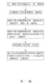
[第一圖]係為本發明機器手臂的換刀方法的步驟流程圖。[The first figure] is a flow chart of the steps of the tool changing method of the robotic arm of the present invention.
[第二圖]係實施本發明機器手臂的換刀方法的機器手臂固定著第一連接板的外觀示意圖。[The second figure] is a schematic diagram of the appearance of the first connecting plate fixed on the robot arm implementing the tool changing method of the robot arm of the present invention.
[第三圖]係為本發明機器手臂的換刀方法以機器手臂末端軸固定第一連接板,並在複數換刀座中選擇並連接任一第二連接板的示意圖。[The third picture] is a schematic diagram of the tool changing method of the robot arm of the present invention. The end shaft of the robot arm fixes the first connecting plate, and selects and connects any second connecting plate in the plurality of tool changing seats.
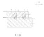
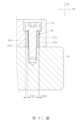
[第四圖]係為本發明機器手臂的換刀方法的換刀座與底座的旋轉剖面圖一。[Fig. 4] is a
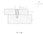
[第五圖]係為本發明機器手臂的換刀方法的換刀座與底座結合構造的剖面圖二。[FIG.5] is the second cross-sectional view of the combined structure of the tool changing seat and the base of the tool changing method of the robotic arm of the present invention.
[第六圖]係為本發明機器手臂的換刀方法的換刀座與底座結合構造的剖面圖三。[Figure 6] is the third cross-sectional view of the combined structure of the tool changing seat and the base of the tool changing method of the robotic arm of the present invention.
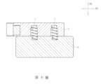
[第七圖]係為本發明機器手臂的換刀方法的換刀座與底座結合構造的剖面圖四,顯示第三操作外力F3作用於換刀座。[Figure 7] is a
[第八圖]係為本發明機器手臂的換刀方法的換刀座與底座結合構造的剖面圖五,顯示第二操作外力F2作用於換刀座。[Eighth Figure] is the fifth sectional view of the combined structure of the tool changer base and the base of the robot arm tool change method of the present invention, showing that the second external force F2 acts on the tool changer base.
[第九圖]係為本發明機器手臂的換刀方法的換刀座與底座結合構造的剖面圖六,顯示第一操作外力F1作用於換刀座。[Figure 9] is a
[第十圖]係為本發明機器手臂的換刀方法的換刀座與底座結合構造的剖面圖七,顯示第一操作外力F1作用於換刀座時,當時彈簧的狀態。[Picture 10] is a
[第十一圖]係為本發明機器手臂的換刀方法的換刀座與底座結合構造的剖面圖八,顯示傾斜操作外力F4作用於換刀座。[Picture 11] is a cross-sectional view eighth of the combination structure of the tool change seat and the base of the tool change method of the robot arm of the present invention, showing that the tilting operation external force F4 acts on the tool change seat.
[第十二圖]係為本發明機器手臂的換刀方法的換刀座與底座結合構造的剖面圖九,其中套筒具有不對稱的壁厚。[Figure 12] is a sectional figure 9 of the combined structure of the tool changing seat and the base of the tool changing method of the robotic arm of the present invention, wherein the sleeve has an asymmetric wall thickness.
下列所述的實施例,只是輔助本說明發明機器手臂的換刀方法的具體步驟,並非用以限制本發明。實施例中列舉的第一方向、第二方向與第三方向是為了方便描述空間關係,本發明自由度的方向並不以此為限。實施例中的第一連接板沿著第二方向接近與遠離第一連接板,第一連接板並沿著第一方向將第二連接板帶離換刀座或帶返換刀座,但利用不同構造的第一連接板與第二連接板,第一連接板也可以從其他方向接近或遠離第二連接板,例如DK3681679專利案的第一連接板沿著第一方向接近與遠離第一連接板,第一連接板同樣沿著第一方向將第二連接板帶離換刀座或帶返換刀座,此種第一連接板與第二連接板的移動方式,也可以實施在本發明。The following embodiments are only to assist the present invention in explaining the specific steps of the tool changing method of the robotic arm, and are not intended to limit the present invention. The first direction, the second direction and the third direction listed in the embodiment are for convenience of describing the spatial relationship, and the directions of degrees of freedom in the present invention are not limited thereto. In the embodiment, the first connecting plate approaches and moves away from the first connecting plate along the second direction, and the first connecting plate takes the second connecting plate away from the tool change seat or brings back the tool change seat along the first direction, but using Different configurations of the first connecting plate and the second connecting plate, the first connecting plate can also approach or move away from the second connecting plate from other directions, for example, the first connecting plate of the DK3681679 patent approaches and moves away from the first connecting plate along the first direction plate, the first connecting plate also takes the second connecting plate away from the tool changer seat or brings back the tool changer seat along the first direction, this kind of moving mode of the first connecting plate and the second connecting plate can also be implemented in the present invention .
參閱第一圖所示,本發明為一種機器手臂的換刀方法,包含下列步驟:在一機器手臂末端軸結合一第一連接板;在複數換刀座設置複數第二連接板;該機器手臂末端軸帶動該第一連接板執行一連接操作而選擇連接任一上述第二連接板,並將前述第二連接板帶離前述換刀座;該機器手臂末端軸帶動該第一連接板與所連接的前述第二連接板返回前述換刀座,並執行一分離操作使該第一連接板分離於前述第二連接板;使前述換刀座具備的一自由度;前述換刀座在前述連接操作與前述分離操作中藉該自由度而自行移位,以克服該第一連接板的一位置誤差,使該第一連接板可以連接或分離於前述第二連接板。As shown in the first figure, the present invention is a tool changing method for a robot arm, which includes the following steps: connecting a first connecting plate to a shaft at the end of a robot arm; setting a plurality of second connecting plates on a plurality of tool changing seats; the robot arm The end shaft drives the first connecting plate to perform a connection operation to select any one of the above-mentioned second connecting plates, and takes the second connecting plate away from the aforementioned tool changer seat; the end shaft of the robot arm drives the first connecting plate and the The connected second connecting plate returns to the aforementioned tool changer seat, and performs a separation operation to separate the first connecting plate from the aforementioned second connecting plate; a degree of freedom is provided for the aforementioned tool changer seat; the aforementioned tool changer seat is in the aforementioned connection During the operation and the separation operation, the degree of freedom is used to displace itself, so as to overcome a position error of the first connecting plate, so that the first connecting plate can be connected or separated from the second connecting plate.
請參閱第二圖,機器手臂末端軸A固定或延伸有一第一連接板1,機器手臂接受一程式控制,使機器手臂末端軸A沿著一預設路徑移動。Please refer to the second figure, the end axis A of the robot arm is fixed or extended with a first connecting
請配合第二圖與第三圖,機器手臂末端軸A帶著第一連接板1,在複數的換刀座2之間移動,每一換刀座2皆可容納一第二連接板3,不同的第二連接板3固定著不同的刀具或工具件(圖中未示出刀具或工具件),藉由第一連接板1選擇連接任一第二連接板3,並將第二連接板3帶離或帶返換刀座2,機器手臂能在各換刀座2之間交換攜帶各種不同的刀具或工具件,以完成特定的加工程序。Please refer to Figure 2 and Figure 3, the axis A at the end of the robotic arm carries the first connecting
第三圖中的機器手臂末端軸A帶著第一連接板1執行一連接操作,在此連接操作中,第一連接板1沿著第二方向D2接近並連接該第二連接板3,然後機器手臂末端軸A帶著第一連接板1沿著第一方向D1將所選擇的第二連接板3帶離換刀座2。The end axis A of the robot arm in the third figure carries the first connecting
第三圖中機器手臂末端軸A帶著第一連接板1與所選擇的第二連接板3也會執行一分離操作,在此分離操作中,機器手臂末端軸A、第一連接板1與所選擇的第二連接板3三者共同沿著第二方向D2返回換刀座2,當第二連接板3固定在換刀座2後,機器手臂末端軸A帶著第一連接板1沿著第一方向D1遠離第二連接板3。In the third figure, the end axis A of the robot arm with the first connecting
請參閱第三圖、第四圖與第五圖,換刀座2沿著第二方向D2結合在固定不動的一底座4上,換刀座2具有一自由度,可以在第一方向D1、第二方向D2與第三方向D3上相對移動於底座4或相對傾斜於底座4。第四圖是換刀座2與底座4之間的旋轉剖面,換刀座2沿著第二方向D2設有二個貫通孔21,二個貫通孔21皆包含一第一孔段211與一第二孔段212,該第一孔段211與該第二孔段212之間皆具有一階面213。底座4對應上述貫通孔21而沿著第二方向D2設有二個螺紋孔41。二螺絲5分別穿經貫通孔21而螺合於螺紋孔41,將換刀座2與底座4互相結合。上述二螺絲5分別套設有套筒6,二螺絲5的螺絲頭51位於該第一孔段211中,每一螺絲頭51與第一孔段211的孔壁之間在第三方向D3上保留有第三上間隙G31。前述套筒6位於該第二孔段212中,每一套筒6在第三方向D3的高度大於前述第二孔段212在第三方向D3的高度,套筒6與第二孔段212的孔壁在第三方向D3上保留有第三下間隙G32,在本實施例中,螺絲頭51、第一孔段211的斷面、套筒6與第二孔段212的斷面等都是圓形,第三上間隙G31與第三下間隙G32的間隙距離相同。該第三上間隙G31或是該第三下間隙G32,形成了前述自由度在第三方向D3上的一第三行程。任一螺絲頭51的一螺絲頭底面511緊抵於套筒6的端部,由於套筒6在第三方向D3的高度大於前述第二孔段212在第三方向D3的高度,因此螺絲頭底面511與階面213之間在該第二方向D2形成有一第二間隙G2,該第二間隙G2形成了前述自由度在第二方向D2上的一第二行程。第五圖是換刀座2與底座4在另一方向的剖面,同樣地,每一螺絲頭51與第一孔段211的孔壁之間在第一方向D1上具有第一上間隙G11,每一套筒6與第二孔段212的孔壁在第一方向D1上具有第一下間隙G12,在本實施例中,第一上間隙G11與第一下間隙G12的間隙距離相同,該第一上間隙G11或是第一下間隙G12,形成了前述自由度在第一方向D1上的一第一行程。在本實施例中,第四圖呈現的換刀座2的位置為一預設位置,代表換刀座2與底座4完成組裝後,換刀座2的原始位置。Please refer to the third figure, the fourth figure and the fifth figure, the
請參閱第三圖與第六圖,換刀座2沿著第二方向D2設有至少一第一盲孔22,底座4沿著第二方向D2對應前述第一盲孔22而設有相同數量的第二盲孔42。前述第一盲孔22與第二盲孔42的斷面皆為圓形,彼此共同形成至少一封閉空間,該封閉空間中均容置有彈簧7,所述封閉空間在第二方向D2的兩端設成較小,用以固定彈簧7的二端,除封閉空間的上述兩端以外,封閉空間的直徑大於彈簧7的外徑,使得彈簧7不會干涉換刀座2的自由度。由於封閉空間與彈簧7的外徑皆為圓形,換刀座2在垂直於第二方向D2的任一輻射方向上的有限行程的移動,也都不會受到彈簧7的干涉。Please refer to the third figure and the sixth figure, the
請參閱第三圖與第七圖,當第一連接板1與第二連接板3在執行連接操作或分離操作的過程中,因為機器手臂末端軸A的路徑誤差,會使第一連接板1產生一位置誤差,該位置誤差導致有一操作外力作用於第二連接板3與換刀座2。為方便說明,本實施例將上述操作外力在第一方向D1的分力標示為第一操作外力F1,上述操作外力在第二方向D2的分力標示為第二操作外力F2,上述操作外力在第三方向D3的分力標示為第三操作外力F3。當第三操作外力F3作用於換刀座2,換刀座2將沿第三方向D3相對於底座4移動一第三行程,該第三行程為有限行程,當第一孔段211碰觸螺絲頭51或是第二孔段212碰觸套筒6時,即為該有限行程的終點,第三行程的最大距離等於第四圖所示的第三上間隙G31或第三下間隙G32。當換刀座2沿第三方向D3相對於底座4移動該第三行程時,封閉空間中的彈簧7沿著第三方向D3彎曲。當該第三操作外力F3消失時,彈簧7對換刀座2施予一復位力,使換刀座2回到如第四圖所示的位置。Please refer to the third figure and the seventh figure, when the first connecting
請參閱第三圖與第八圖,當第二操作外力F2作用於換刀座2,換刀座2將沿第二方向D2相對於底座4移動一第二行程,該第二行程為有限行程,當階面213碰觸螺絲頭底面511時,即為該有限行程的終點,第二行程的最大距離等於第四圖所示的第二間隙G2。當換刀座2沿第二方向D2相對於底座4移動該第二行程時,封閉空間中的彈簧7沿著第二方向D2伸長。當該第二操作外力F2消失時,彈簧7對換刀座2施予一復位力,使換刀座2回到第四圖所示的位置。Please refer to the third figure and the eighth figure, when the second operation external force F2 acts on the
請參閱第三圖、第九圖與第十圖,當第一操作外力F1作用於換刀座2,換刀座2將沿第一方向D1相對於底座4移動一第一行程,該第一行程為有限行程,當第一孔段211碰觸螺絲頭51或是第二孔段212碰觸套筒6時,即為該有限行程的終點,第一行程的最大距離等於第五圖所示的第一上間隙G11或第一下間隙G12。當換刀座2將沿第一方向D1相對於底座4移動該第一行程時,封閉空間中的彈簧7沿著第一方向D1彎曲。當該第一操作外力F1消失時,彈簧7對換刀座2施予一復位力,使換刀座2回到第五圖所示的位置。Please refer to the third figure, the ninth figure and the tenth figure, when the first operation external force F1 acts on the
請參閱第三圖與第十一圖,如果操作外力是多方向分力的組合,例如有第二操作外力F2與第三操作外力F3同時作用於換刀座2,則換刀座2會產生傾斜的移動。如第十一圖所示,一傾斜操作外力F4為前述第二操作外力F2與前述第三操作外力F3的結合,該傾斜操作外力F4作用於於換刀座2,使第四圖所示的第三上間隙G31或第三下間隙G32產生變化,同時第二間隙G2也產生變化,換刀座2將相對底座4傾斜一角度θ,亦即換刀座2以第一方向D1為軸心,旋轉了一角度。此時,封閉空間中的彈簧7根據換刀座2的傾斜而變形,當該傾斜操作外力F4消失時,彈簧7對換刀座2施予一復位力,使換刀座2回到第四圖所示的位置。Please refer to Figure 3 and Figure 11. If the operating external force is a combination of multi-directional force components, for example, the second external operating force F2 and the third external operating force F3 act on the
同理,第一操作外力F1、第二操作外力F2與第三操作外力F3的任意組合,換刀座2都能在各維度相對移動於底座4或相對傾斜於底座4,這些移動或傾斜即是換刀座2的移動自由度與旋轉自由度。當換刀座2相對移動於底座4或相對傾斜於底座4,彈簧7都能根據換刀座2的移動或傾斜而適當在各維度變形,彈簧7的變形賦予一復位力給換刀座2,使得第一操作外力F1、第二操作外力F2、第三操作外力F3或傾斜操作外力F4消失時,換刀座2都能回到第四圖與第五圖所示的位置。Similarly, with any combination of the first external force F1, the second external force F2 and the third external force F3, the
請參閱第四圖與第五圖,本發明的第一上間隙G11、第一下間隙G12、第二間隙G2、第三上間隙G31與第三下間隙G32都是可調整的。藉由更換不同壁厚的套筒6,可以改變第三下間隙G32與第一下間隙G12的大小。藉由更換不同高度的套筒6,可以改變第二間隙G2的大小,藉由更換不同尺寸的螺絲5,改變螺絲頭51的直徑,可以改變第三上間隙G31與第一上間隙G11的大小。透過第一上間隙G11、第一下間隙G12、第二間隙G2、第三上間隙G31與第三下間隙G32的調整,使得前述第一行程、第二行程與第三行程也獲得調整,亦即換刀座2的自由度是可以改變的。在第四圖與第五圖所示的狀態,上述更換不同壁厚的套筒6,指的是將壁厚較小的套筒6更換為壁厚較大的套筒6,或是將壁厚較大的套筒6更換為壁厚較小的套筒6,無論如何更換,套筒6的壁厚是對稱的,藉此方式,換刀座2的自由度可以進行對稱式調整。以第四圖為例,換刀座2位於預設位置,藉由更換不同壁厚的套筒6,換刀座2所獲得的自由度改變在第三方向D3上將是對稱的。Please refer to the fourth and fifth figures, the first upper gap G11 , the first lower gap G12 , the second gap G2 , the third upper gap G31 and the third lower gap G32 of the present invention are all adjustable. The size of the third lower gap G32 and the first lower gap G12 can be changed by replacing the
請參閱第十二圖,上述實施例所示的套筒6也可以是一偏心套筒6A,亦即偏心套筒6A的內徑軸心與外徑軸心互相平行但不在同一軸線上,偏心套筒6A具有厚度不相等的一第一壁61A與一第二壁62A,該第一壁61A的外緣與第二孔段212A的孔壁形成一第三下間隙G32A,該第二壁62A的外緣與第二孔段212A的孔壁形成另一第三下間隙G33A,前述二個第三下間隙G32A、G32A不相等,當換刀座2A沿著第三方向D3相對移動於底座4A時,換刀座2A所獲得的自由度改變在第三方向D3上將是不對稱的,藉此使換刀座2A的自由度獲得非對稱式調整。Please refer to the twelfth figure, the
綜合上述實施例之說明,當可充分瞭解本發明之操作、使用及本發明產生之功效,惟以上所述實施例僅係為本發明之較佳實施例,當不能以此限定本發明實施之範圍,即依本發明申請專利範圍及發明說明內容所作簡單的等效變化與修飾,皆屬本發明涵蓋之範圍內。Based on the description of the above-mentioned embodiments, it is possible to fully understand the operation of the present invention, use and the effect that the present invention produces, but the above-mentioned embodiments are only preferred embodiments of the present invention, and should not be used to limit the implementation of the present invention. The scope, that is, the simple equivalent changes and modifications made according to the patent scope of the present invention and the content of the description of the invention, all fall within the scope of the present invention.
Claims (7)
Translated fromChinesePriority Applications (2)
| Application Number | Priority Date | Filing Date | Title |
|---|---|---|---|
| TW110146631ATWI804101B (en) | 2021-12-13 | 2021-12-13 | Tool changing method for robotic arm |
| US17/667,851US12048999B2 (en) | 2021-12-06 | 2022-02-09 | Method for performing tool change with robot arm |
Applications Claiming Priority (1)
| Application Number | Priority Date | Filing Date | Title |
|---|---|---|---|
| TW110146631ATWI804101B (en) | 2021-12-13 | 2021-12-13 | Tool changing method for robotic arm |
Publications (2)
| Publication Number | Publication Date |
|---|---|
| TWI804101Btrue TWI804101B (en) | 2023-06-01 |
| TW202322961A TW202322961A (en) | 2023-06-16 |
Family
ID=87803296
Family Applications (1)
| Application Number | Title | Priority Date | Filing Date |
|---|---|---|---|
| TW110146631ATWI804101B (en) | 2021-12-06 | 2021-12-13 | Tool changing method for robotic arm |
Country Status (1)
| Country | Link |
|---|---|
| TW (1) | TWI804101B (en) |
Citations (7)
| Publication number | Priority date | Publication date | Assignee | Title |
|---|---|---|---|---|
| US4636135A (en)* | 1983-03-11 | 1987-01-13 | Societe Syspro | Tool-holder for industrial robot |
| TW569855U (en)* | 2003-05-19 | 2004-01-01 | Lin Ruey Knifeware Ind Co Ltd | Cutting tools with tightening device |
| US20160052146A1 (en)* | 2014-08-20 | 2016-02-25 | Ati Industrial Automation, Inc. | Robotic tool changer with tool stand decouple power supply |
| TW201910040A (en)* | 2017-07-26 | 2019-03-16 | 騰升科技股份有限公司 | Automatic tool changing device for combining a tool with a tool arbor or separating the tool from the tool arbor |
| CN210648845U (en)* | 2019-10-23 | 2020-06-02 | 张琳 | Rolling cutting tool, tool assembly and beveling machine |
| CN211803907U (en)* | 2020-02-28 | 2020-10-30 | 浙江双铭工贸有限公司 | Multi-cutter mounting seat and multi-cutter mounting device |
| WO2020249465A1 (en)* | 2019-06-12 | 2020-12-17 | Triplea Robotics Aps | Tool changer for collaborative robots, a robot tool changer system and a method for connecting a tool to a robot arm |
- 2021
- 2021-12-13TWTW110146631Apatent/TWI804101B/enactive
Patent Citations (7)
| Publication number | Priority date | Publication date | Assignee | Title |
|---|---|---|---|---|
| US4636135A (en)* | 1983-03-11 | 1987-01-13 | Societe Syspro | Tool-holder for industrial robot |
| TW569855U (en)* | 2003-05-19 | 2004-01-01 | Lin Ruey Knifeware Ind Co Ltd | Cutting tools with tightening device |
| US20160052146A1 (en)* | 2014-08-20 | 2016-02-25 | Ati Industrial Automation, Inc. | Robotic tool changer with tool stand decouple power supply |
| TW201910040A (en)* | 2017-07-26 | 2019-03-16 | 騰升科技股份有限公司 | Automatic tool changing device for combining a tool with a tool arbor or separating the tool from the tool arbor |
| WO2020249465A1 (en)* | 2019-06-12 | 2020-12-17 | Triplea Robotics Aps | Tool changer for collaborative robots, a robot tool changer system and a method for connecting a tool to a robot arm |
| CN210648845U (en)* | 2019-10-23 | 2020-06-02 | 张琳 | Rolling cutting tool, tool assembly and beveling machine |
| CN211803907U (en)* | 2020-02-28 | 2020-10-30 | 浙江双铭工贸有限公司 | Multi-cutter mounting seat and multi-cutter mounting device |
Also Published As
| Publication number | Publication date |
|---|---|
| TW202322961A (en) | 2023-06-16 |
Similar Documents
| Publication | Publication Date | Title |
|---|---|---|
| JP5987043B2 (en) | Work fixing device that presses multiple parts of the work | |
| JP5766235B2 (en) | Robot arm | |
| JP3117118B2 (en) | Multi-degree-of-freedom positioning mechanism | |
| US10639788B2 (en) | Parallel link robot | |
| WO2017041645A1 (en) | Flexible unit and flexible wrist for precision assembly of industrial robots | |
| JP6472854B1 (en) | Work equipment | |
| TWI607823B (en) | Floating processing platform, floating processing system and floating processing method | |
| US20180185102A1 (en) | Parallel-type micro robot and surgical robot system having the same | |
| WO2017043420A1 (en) | Composite work device using link operating device | |
| TWI804101B (en) | Tool changing method for robotic arm | |
| JP6527782B2 (en) | Work device using parallel link mechanism | |
| JPH11104987A (en) | Parallel link mechanism | |
| JP4822558B2 (en) | Home position return method of parallel mechanism | |
| JP5325551B2 (en) | Gonio stage equipment | |
| TWI487593B (en) | Three axis on one surface designed oblique-driven platform | |
| KR102716550B1 (en) | Robot Hands, Robots and Fixtures | |
| US20230173688A1 (en) | Method for performing tool change with robot arm | |
| KR101930063B1 (en) | Variable passive compliance apparatus and variable passive compliance gripper having the same | |
| CN205507195U (en) | Level crossing adjusting device | |
| JP5602676B2 (en) | Movable body support device | |
| KR100674109B1 (en) | Hybrid parallel mechanism for complex machining | |
| JP5377090B2 (en) | Processing equipment | |
| JP2021053767A (en) | Machine tool | |
| WO2021109062A1 (en) | Multi-degree-of-freedom parallel mechanism | |
| JP2020199576A (en) | Processing mechanism |