TWI798669B - Knee rehabilitation device - Google Patents
Knee rehabilitation deviceDownload PDFInfo
- Publication number
- TWI798669B TWI798669BTW110111250ATW110111250ATWI798669BTW I798669 BTWI798669 BTW I798669BTW 110111250 ATW110111250 ATW 110111250ATW 110111250 ATW110111250 ATW 110111250ATW I798669 BTWI798669 BTW I798669B
- Authority
- TW
- Taiwan
- Prior art keywords
- unit
- thigh
- support
- linkage
- sole
- Prior art date
Links
- 210000003127kneeAnatomy0.000titleabstractdescription6
- 210000000689upper legAnatomy0.000claimsabstractdescription93
- 244000309466calfSpecies0.000claimsabstractdescription55
- 210000000629knee jointAnatomy0.000claimsabstractdescription47
- 238000005452bendingMethods0.000claimsdescription10
- 238000004891communicationMethods0.000claimsdescription10
- 210000003423ankleAnatomy0.000claimsdescription8
- 230000008859changeEffects0.000claimsdescription5
- 238000005259measurementMethods0.000claims1
- 230000000694effectsEffects0.000abstractdescription10
- 210000002414legAnatomy0.000description7
- 210000002683footAnatomy0.000description6
- 238000010586diagramMethods0.000description4
- 230000007547defectEffects0.000description3
- 230000003247decreasing effectEffects0.000description2
- 238000013461designMethods0.000description2
- 230000037396body weightEffects0.000description1
- 230000007812deficiencyEffects0.000description1
- 230000006872improvementEffects0.000description1
- 238000000034methodMethods0.000description1
- 238000012986modificationMethods0.000description1
- 230000004048modificationEffects0.000description1
- 238000011160researchMethods0.000description1
Images


Landscapes
- Massaging Devices (AREA)
- Rehabilitation Tools (AREA)
Abstract
Description
Translated fromChinese本發明涉及一種復健裝置,尤其涉及一種膝關節復健裝置。The invention relates to a rehabilitation device, in particular to a knee joint rehabilitation device.
現有復健裝置大多是由移動輸送帶及設置於移動輸送帶兩側的輔助支撐件所組成。於實際復健時,病患能攙扶輔助支撐件協助支撐其體重,並且於移動輸送帶的緩慢帶領下而逐步行走,從而達到復健膝關節的效果。Most of the existing rehabilitation devices are composed of a moving conveyor belt and auxiliary supports arranged on both sides of the moving conveyor belt. During the actual rehabilitation, the patient can support the auxiliary supporting member to help support his body weight, and walk gradually under the slow guidance of the moving conveyor belt, so as to achieve the effect of knee joint rehabilitation.
然而,現有復健裝置僅能提供具備站立能力的病患進行復健,但未提供無法站立(例如:雙腿無力)或無法自主驅動腿部移動(例如:植物人)的病患進行復健。也就是說,現有復健裝置存在無法提供病患被動地復健膝關節的缺點。However, existing rehabilitation devices can only provide rehabilitation for patients who have the ability to stand, but do not provide rehabilitation for patients who cannot stand (for example: legs are weak) or cannot independently drive their legs to move (for example: vegetative). That is to say, existing rehabilitation devices have the disadvantage of being unable to provide patients with passive rehabilitation of knee joints.
於是,本發明人認為上述缺陷可改善,乃特潛心研究並配合科學原理的運用,終於提出一種設計合理且有效改善上述缺陷的本發明。Therefore, the inventor believes that the above-mentioned defects can be improved, Naite devoted himself to research and combined with the application of scientific principles, and finally proposed an invention with reasonable design and effective improvement of the above-mentioned defects.
本發明所要解決的技術問題在於,針對現有技術的不足提供一種膝關節復健裝置,能有效地改善現有復健裝置所可能產生的缺陷。The technical problem to be solved by the present invention is to provide a knee joint rehabilitation device aimed at the deficiencies of the prior art, which can effectively improve the possible defects of the existing rehabilitation device.
本發明實施例公開一種膝關節復健裝置,包括:一底座,具有相反的第一端及一第二端;一大腿支撐單元,設置於所述底座上,所述大腿支撐單元包含:一大腿連動件,樞接於所述第一端,所述大腿連動件能相對所述底座樞擺;及一大腿支撐件,設置於所述大腿連動件上;一滑軌,設置於所述底座於所述第一端及所述第二端之間,所述滑軌具有一滑移方向;一移動單元,設置於所述滑軌上,所述移動單元能於所述滑軌上沿所述滑移方向移動;一小腿支撐單元,設置於所述移動單元上,所述小腿支撐單元包含:一小腿連動件,樞接於所述移動單元,所述小腿連動件與所述大腿連動件相互樞接,並且所述小腿連動件能以所述移動單元為軸心樞擺,從而帶動所述大腿連動件樞擺;及一小腿支撐件,設置於所述小腿連動件上;一第一推伸單元,設置於所述底座上,所述第一推伸單元能推動所述大腿支撐單元及所述小腿支撐單元的其中一者,使所述小腿支撐件能相對所述大腿支撐件沿所述滑移方向往復移動;一腳掌支撐單元,設置於所述移動單元上,並且所述腳掌支撐單元包含:一腳掌連動件,樞接所述移動單元,所述腳掌連動件能以所述移動單元為軸心樞擺;及一腳掌支撐件,設置於所述腳掌連動件上;以及一第二推伸單元,設置於所述移動單元上,所述第二推伸單元能推動所述腳掌支撐單元,使所述腳掌支撐件能相對所述移動單元往復樞擺;一控制單元,電性耦接所述第一推伸單元及所述第二推伸單元,所述控制單元能控制所述第一推伸單元及所述第二推伸單元的推動速度及頻率。The embodiment of the present invention discloses a knee joint rehabilitation device, comprising: a base with opposite first ends and a second end; a thigh support unit arranged on the base, and the thigh support unit includes: a thigh Linking piece, pivotally connected to the first end, the thigh linking piece can be relativelyThe base is pivoted; and a thigh support member is arranged on the thigh linkage member; a slide rail is arranged on the base between the first end and the second end, and the slide rail has a sliding direction; a moving unit arranged on the slide rail, and the moving unit can move along the sliding direction on the sliding rail; a calf support unit is arranged on the moving unit, and the The calf support unit includes: a lower leg linkage, pivotally connected to the moving unit, the lower leg linkage and the thigh linkage are pivotally connected to each other, and the lower leg linkage can be pivoted around the moving unit pendulum, so as to drive the pivot of the thigh linkage; and a calf support, arranged on the lower leg linkage; a first extension unit, arranged on the base, and the first extension unit can push One of the thigh support unit and the calf support unit enables the calf support to move back and forth along the sliding direction relative to the thigh support; a sole support unit is arranged on the moving unit , and the sole support unit includes: a sole linkage, pivotally connected to the mobile unit, and the sole linkage can pivot with the movement unit as the axis; and a sole support, arranged on the sole linkage and a second extension unit arranged on the moving unit, the second extension unit can push the sole support unit so that the sole support can pivot back and forth relative to the movement unit; A control unit, electrically coupled to the first stretching unit and the second stretching unit, the control unit can control the pushing speed and frequency of the first stretching unit and the second stretching unit .
本發明實施例另外公開一種膝關節復健裝置,包括:一底座,具有相反的第一端及一第二端;一大腿支撐單元,設置於所述底座上,所述大腿支撐單元包含:一大腿連動件,樞接於所述第一端,所述大腿連動件能相對所述底座樞擺;及一大腿支撐件,設置於所述大腿連動件上;一滑軌,設置於所述底座於所述第一端及所述第二端之間,所述滑軌具有一滑移方向;一移動單元,設置於所述滑軌上,所述移動單元能於所述滑軌上沿所述滑移方向移動;一小腿支撐單元,設置於所述移動單元上,所述小腿支撐單元包含:一小腿連動件,樞接於所述移動單元,所述小腿連動件與所述大腿連動件相互樞接,並且所述小腿連動件能以所述移動單元為軸心樞擺,從而帶動所述大腿連動件樞擺;及一小腿支撐件,設置於所述小腿連動件上;一推伸單元,設置於所述底座上,所述推伸單元能推動所述大腿支撐單元及所述小腿支撐單元的其中一者,使所述小腿支撐件能相對所述大腿支撐件沿所述滑移方向往復移動;以及一控制單元,電性耦接所述推伸單元,所述控制單元能控制所述推伸單元的推動速度及頻率。The embodiment of the present invention further discloses a knee joint rehabilitation device, comprising: a base with opposite first ends and a second end; a thigh support unit arranged on the base, and the thigh support unit includes: a a thigh linking piece pivotally connected to the first end, the thigh linking piece can pivot relative to the base; a thigh support set on the thigh linking piece; a slide rail set on the base Between the first end and the second end, the slide rail has a sliding direction; a moving unit is arranged on the slide rail, and the moving unit can move along the slide rail along the moving in the sliding direction; the lower leg supporting unit is arranged on the moving unit, and the lower leg supporting unit includes: a lower leg link, pivotally connected to the moving unit, and the lower leg link is connected to the thighThe linking parts are pivotally connected to each other, and the calf linking part can pivot with the moving unit as the axis, thereby driving the thigh linking part to pivot; and the calf support part is arranged on the calf linking part; The stretching unit is arranged on the base, and the stretching unit can push one of the thigh support unit and the calf support unit so that the calf support can move along the leg support relative to the thigh support. reciprocating movement in a sliding direction; and a control unit electrically coupled to the stretching unit, the control unit can control the pushing speed and frequency of the stretching unit.
綜上所述,本發明實施例所公開的膝關節復健裝置,能通過“所述小腿連動件與所述大腿連動件相互樞接,並且所述小腿連動件能以所述移動單元為軸心樞擺,從而帶動所述大腿連動件樞擺”及“所述推伸單元能推動所述大腿支撐單元及所述小腿支撐單元的其中一者,使所述小腿支撐件能相對所述大腿支撐件沿所述滑移方向往復移動”的設計,使病患的膝關節能被動地被帶動彎曲,從而實現復健效果。To sum up, the knee joint rehabilitation device disclosed in the embodiments of the present invention can be pivotally connected to each other through "the lower leg linkage and the thigh linkage, and the lower leg linkage can take the moving unit as the axis." The center pivots, thereby driving the thigh linkage to pivot" and "the stretching unit can push one of the thigh support unit and the calf support unit, so that the calf support can move relative to the thigh The design of the supporting member reciprocatingly moving along the sliding direction enables the patient's knee joint to be passively driven to bend, thereby realizing the rehabilitation effect.
為使能更進一步瞭解本發明的特徵及技術內容,請參閱以下有關本發明的詳細說明與圖式,然而所提供的圖式僅用於提供參考與說明,並非用來對本發明加以限制。In order to further understand the features and technical content of the present invention, please refer to the following detailed description and drawings related to the present invention. However, the provided drawings are only for reference and description, and are not intended to limit the present invention.
100:膝關節復健裝置100: Knee joint rehabilitation device
1:底座1: base
11:第一端11: first end
12:第二端12: Second end
13:長槽13: Long slot
2:大腿支撐單元2: Thigh support unit
21:大腿連動件21: Thigh link
211:第一伸縮連桿211: The first telescopic link
22:大腿支撐件22: Thigh support
3:滑軌3: slide rail
4:第一推伸單元4: The first extension unit
5:移動單元5: Mobile unit
6:小腿支撐單元6: calf support unit
61:小腿連動件61: Calf linkage
611:第二伸縮連桿611: The second telescopic link
62:小腿支撐件62:Calf support
7:第二推伸單元7: The second extension unit
7B:擺動單元7B: Swing unit
8:控制單元8: Control unit
81:無線通訊模組81:Wireless communication module
82:控制模組82:Control module
9:腳掌支撐單元9: Foot support unit
91:腳掌連動件91: Foot linkage
911:第一段911: first paragraph
912:第二段912: second paragraph
92:腳掌支撐件92: sole support
93:擺動桿93: swing rod
PSM:壓力感測模組PSM: Pressure Sensing Module
200:電子設備200: Electronic equipment
D1:長度方向D1: Length direction
D2:高度方向D2: height direction
D3:橫向方向D3: Horizontal direction
S1:滑移方向S1: sliding direction
θ1、θ2:角度θ1, θ2: Angle
圖1為本發明第一實施例的膝關節復健裝置的立體示意圖。FIG. 1 is a three-dimensional schematic diagram of a knee joint rehabilitation device according to a first embodiment of the present invention.
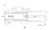
圖2為本發明第一實施例的膝關節復健裝置的俯視示意圖。FIG. 2 is a schematic top view of the knee joint rehabilitation device according to the first embodiment of the present invention.
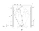
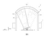
圖3為本發明第一實施例的小腿支撐件相對大腿支撐件移動時的狀態示意圖。Fig. 3 is a schematic diagram of the state when the calf support moves relative to the thigh support according to the first embodiment of the present invention.
圖4為圖3的側視示意圖。FIG. 4 is a schematic side view of FIG. 3 .
圖5為本發明第一實施例的腳掌支撐單元與第二推伸單元的俯視示意圖。5 is a schematic top view of the sole support unit and the second stretching unit according to the first embodiment of the present invention.
圖6為本發明第一實施例的膝關節復健裝置的電路方塊示意圖。FIG. 6 is a schematic circuit block diagram of the knee joint rehabilitation device according to the first embodiment of the present invention.
圖7為本發明第二實施例的腳掌支撐單元與第二推伸單元的俯視示意圖。7 is a schematic top view of the sole support unit and the second stretching unit according to the second embodiment of the present invention.
圖8為本發明第二實施例的另一態樣的腳掌支撐單元與第二推伸單元的俯視示意圖。8 is a schematic top view of another aspect of the sole support unit and the second stretching unit of the second embodiment of the present invention.
圖9為本發明第二實施例的膝關節復健裝置的電路方塊示意圖。FIG. 9 is a schematic circuit block diagram of a knee joint rehabilitation device according to a second embodiment of the present invention.
以下是通過特定的具體實施例來說明本發明所公開有關“膝關節復健裝置”的實施方式,本領域技術人員可由本說明書所公開的內容瞭解本發明的優點與效果。本發明可通過其他不同的具體實施例加以施行或應用,本說明書中的各項細節也可基於不同觀點與應用,在不悖離本發明的構思下進行各種修改與變更。另外,本發明的附圖僅為簡單示意說明,並非依實際尺寸的描繪,事先聲明。以下的實施方式將進一步詳細說明本發明的相關技術內容,但所公開的內容並非用以限制本發明的保護範圍。The implementation of the "knee joint rehabilitation device" disclosed in the present invention is described below through specific specific examples. Those skilled in the art can understand the advantages and effects of the present invention from the content disclosed in this specification. The present invention can be implemented or applied through other different specific embodiments, and various modifications and changes can be made to the details in this specification based on different viewpoints and applications without departing from the concept of the present invention. In addition, the drawings of the present invention are only for simple illustration, and are not drawn according to the actual size, which is stated in advance. The following embodiments will further describe the relevant technical content of the present invention in detail, but the disclosed content is not intended to limit the protection scope of the present invention.
應當可以理解的是,雖然本文中可能會使用到“第一”、“第二”、“第三”等術語來描述各種元件或者信號,但這些元件或者信號不應受這些術語的限制。這些術語主要是用以區分一元件與另一元件,或者一信號與另一信號。另外,本文中所使用的術語“或”,應視實際情況可能包括相關聯的列出項目中的任一個或者多個的組合。It should be understood that although terms such as "first", "second", and "third" may be used herein to describe various elements or signals, these elements or signals should not be limited by these terms. These terms are mainly used to distinguish one element from another element, or one signal from another signal. In addition, the term "or" used herein may include any one or a combination of more of the associated listed items depending on the actual situation.
參閱圖1至圖6所示,本實施例提供一種膝關節復健裝置100,所述膝關節復健裝置100能主動地帶動(或牽引)病患的腿部屈膝,從而實現復健膝關節的效果。換句話說,任何病患腿部需要出力的復健裝置,並非本發明所指的膝關節復健裝置。接著,以下將介紹所述膝關節復健裝置100的各元件及其元件之間的連接關係。1 to 6, this embodiment provides a knee
配合圖1及圖2所示,所述膝關節復健裝置100包含一底座1、設置於所述底座1上的一大腿支撐單元2、一滑軌3與一第一推伸單元4、設置於所述滑軌3上的一移動單元5、設置於所述移動單元5上的一小腿支撐單元6、一腳掌支撐單元9與一第二推伸單元7、以及電性耦接所述第一推伸單元4及所述第二推伸單元7的一控制單元8。As shown in FIG. 1 and FIG. 2, the knee
所述底座1於本實施例中為長矩形結構、並且具有一長度方向D1及垂直所述長度方向D1的一高度方向D2,所述底座1沿所述長度方向D1具有相反的一第一端11及一第二端12。此外,所述底座1更進一步地具有沿所述長度方向D1設置的一長槽13。The
所述大腿支撐單元2具有樞接於所述第一端11的一大腿連動件21及設置於所述大腿連動件21上的一大腿支撐件22。詳細地說,所述大腿連動件21於本實施例中是由可調式的兩個第一伸縮連桿211所組成,兩個所述第一伸縮連桿211分別樞接在所述底座1於所述長槽13的兩側,並且兩個所述第一伸縮連桿211以所述第一端11為軸心相對於所述底座1沿所述高度方向D2樞擺(如圖4所示)、也能沿所述長度方向D1增加或減少整體長度,但本發明不受限於此。舉例來說,所述大腿連動件21也可以是不具備調整長度功能的連桿。The
此外,所述大腿支撐件22於本實施例中則為支撐板、並且固定於兩個所述第一伸縮連桿211之間,意即所述大腿支撐件22能隨著兩個所述第一伸縮連桿211樞擺,但本發明不受限此。舉例來說,所述大腿支撐件22也可以是透氣帆布。In addition, the
所述滑軌3沿所述長度方向D1設置於所述底座1上,並且位於所述第一端11及所述第二端12之間。所述滑軌3具有平行所述長度方向D1的一滑移方向S1,並且所述移動單元5能於所述滑軌3上沿所述滑移方向S1移動(如圖2及圖3所示)。此外,於本實施例中,所述滑軌3沿所述長度方向D1的長度是大於所述底座1沿所述長度方向D1的長度的50%,但本發明不受限於此。The
復參圖1、圖2及圖4所示,所述小腿支撐單元6於本實施例中具有樞接於所述移動單元5的一小腿連動件61及設置於所述小腿連動件61上的一小腿支撐件62。其中,所述小腿連動件61與所述大腿連動件21相互樞接,並且所述小腿連動件61能以所述移動單元5為軸心樞擺,從而帶動所述大腿連動件21樞擺。Referring back to Fig. 1, Fig. 2 and Fig. 4, the
具體來說,所述小腿連動件61於本實施例中也是由可調式的兩個第二伸縮連桿611所組成,兩個所述第二伸縮連桿611的一端樞接於所述移動單元5上,而兩個所述第二伸縮連桿611的另一端則分別樞接兩個所述第一伸縮連桿211的一端。兩個所述第二伸縮連桿611能以所述移動單元5為軸心相對於所述底座1沿所述高度方向D2樞擺,從而帶動兩個所述第一伸縮連桿211樞擺。當然,兩個所述第二伸縮連桿611也能沿所述長度方向D1增加或減少整體長度,但本發明不受限於此。舉例來說,所述小腿連動件61也可以是不具備調整長度功能的連桿。Specifically, the
需說明的是,於本實施例中,所述大腿連動件21及所述小腿連動件61都具有伸縮結構(即伸縮連桿),是為了能供病患依腿長進行調整所述大腿支撐件22及所述小腿支撐件62之間的相對位置。然而,所述大腿連動件21及所述小腿連動件61於實務上至少其中一者具有一伸縮結構,就可以達到調整功效。It should be noted that, in this embodiment, both the
此外,所述小腿支撐件62於本實施例中則為支撐板、並且固定於兩個所述第二伸縮連桿611之間,意即所述小腿支撐件62能隨著兩個所述第二伸縮連桿611樞擺,但本發明不受限此。舉例來說,所述小腿支撐件62也可以是透氣帆布。In addition, the
所述第一推伸單元4能推動所述大腿支撐單元2及所述小腿支撐單元6的其中一者,使所述小腿支撐件62能相對所述大腿支撐件22沿所述滑移方向S1往復移動。於實務上,所述第一推伸單元4可以是由一伺服馬達及連接所述伺服馬達的一推桿所組成,所述伺服馬達能驅動所述推桿精準地往復位移動,從而推動所述大腿支撐單元2及所述小腿支撐單元6的其中一者,但本發明不受限於此。The
值得注意的是,配合圖4所示,當所述第一推伸單元4運作時,所述大腿連動件21及所述小腿連動件61之間的最大夾角θ1變化於優選情況下是小於150度。舉例來說,當所述伺服馬達尚未驅動所述推桿移動時,所述大腿連動件21及所述小腿連動件61會呈直線狀態,意即所述大腿連動件21及所述小腿連動件61之間夾角θ1為180度;若當所述伺服馬達驅動所述推桿移動至最遠位置時,所述大腿連動件21及所述小腿連動件61之間的最小夾角θ1為30度,意即前述最小夾角為180度減去150度的最大夾角變化。It is worth noting that, as shown in FIG. 4 , when the
參閱圖1、圖4及圖5所示,所述腳掌支撐單元9於本實施例中包含樞接所述移動單元5的一腳掌連動件91及設置於所述腳掌連動件91的一腳掌支撐件92,所述腳掌連動件91能以所述移動單元5為軸心樞擺,從而帶動所述腳掌支撐件92移動。具體來說,所述腳掌連動件91於本實施例中呈U字狀結構且具有一第一段911及連接所述第一段911兩端的兩個第二段912,兩個所述第二段912樞接於所述移動單元5上,所述第一段911沿垂直所述滑移方向S1(或所述長度方向D1)的一橫向方向D3配置,並且兩個所述第二段912能以所述移動單元5為軸心相對於所述底座1沿所述高度方向D2同步樞擺。換句話說,所述腳掌連動件91能樞擺方向相同於兩個所述第一伸縮桿211及兩個所述第二伸縮桿611。Referring to Fig. 1, Fig. 4 and Fig. 5, the
此外,所述腳掌支撐件92於本實施例中則為呈L字狀的支撐板、並且固定於兩個所述第二段912之間,意即所述腳掌支撐件92能隨著兩個所述第二段912樞擺,但本發明不受限此。舉例來說,所述腳掌支撐件92也可以是透氣帆布。In addition, the
所述第二推伸單元7是位於所述移動單元5上,並且能隨著所述移動單元5沿所述滑軌3移動。另外,所述第二推伸單元7也能推動所述腳掌支撐單元9,使所述腳掌支撐件92能以所述移動單元5為軸心樞擺。於實務上,所述第二推伸單元7可以是由一伺服馬達及連接所述伺服馬達的一推桿所組成,所述伺服馬達能驅動所述推桿精準地往復位移動,從而推動所述腳掌支撐單元9樞擺,但本發明不受限於此。The
值得注意的是,配合圖4所示,當所述第二推伸單元7運作時,所述腳掌連動件91的樞擺角度於優選情況下是小於70度。舉例來說,當所述伺服馬達於驅動所述推桿移動至最遠位置及最近位置時,所述腳掌連動件91的角度θ2變化不會超出70度。It is worth noting that, as shown in FIG. 4 , when the
復參圖1及圖8所示,所述控制單元8能控制所述第一推伸單元4及所述第二推伸單元7的推動速度、位置及頻率。具體來說,所述控制單元8於本實施例中包含一無線通訊模組81(例如:WI-FI®網路介面)及電性耦接所述無線通訊模組81的一控制模組82(例如:MCU),所述無線通訊模組81能用來無線連接一電子設備200(例如:手機),並且接收由所述電子設備200發出的一控制命令至所述控制模組82,使所述控制模組82控制所述第一推伸單元4及所述第二推伸單元7,從而調整所述大腿連動件21、所述小腿連動件61、及所述腳掌連動件91的樞擺角度、樞擺次數、樞擺頻率等。Referring again to FIG. 1 and FIG. 8 , the
於優選情況下,所述膝關節復健裝置100更可以包含電性耦接所述控制單元8的兩個壓力感測模組PSM,其中一個所述壓力感測模組PSM設置於所述大腿支撐件22及所述小腿支撐件62的其中一者、並且能利用壓力變化感測一膝關節的彎曲次數。另一個所述壓力感測模組PSM設置於所述腳掌支撐件92、並且能利用壓力變化感測一腳踝的彎曲次數。In a preferred situation, the knee
詳細地說,兩個所述壓力感測模組PSM能利用壓力變化感測膝關節及腳踝是否達大設定的壓力值,從而判定是否完成一次彎曲以實現彎曲次數的計數功能。兩個所述壓力感測模組PSM會將其計數的彎曲次數以一彎曲次數訊號發送至所述控制模組82,使所述控制模組82能進一步地依據所述彎曲次數訊號控制所述第一推伸單元4及所述第二推伸單元7。In detail, the two pressure sensing modules PSM can use the pressure change to sense whether the knee joint and the ankle reach the maximum set pressure value, so as to determine whether a bending is completed to realize the function of counting the number of bending times. The two pressure sensing modules PSM will send the counted number of times of bending to the
當然,於實際應用時,所述控制模組82更能額外設定多個執行方案。舉例來說,所述執行方案可以是:當體重範圍介於60至70公斤時,執行50~60度夾角變化的膝關節彎曲5次,執行15度角度變化的腳踝彎曲10次,但本發明不受限於此。舉例來說,兩個所述壓力感測模組PSM可以替換為其他能實現彎曲計數的構件,又或者省略設定多個所述執行方案。Of course, in actual application, the
需說明的是,本實施例的所述膝關節復健裝置100能實現的功效包含復健膝關節及腳踝,但設計者能依據其需求省略腳踝復健的功效。換句話說,本發明於其他未繪示的實施例中,所述膝關節復健裝置100僅包含上述底座1、大腿支撐單元2、滑軌3、移動單元5、小腿支撐單元6、推伸單元4、7、及控制單元8。It should be noted that the knee
如圖7至圖9所示,其為本發明的第二實施例,本實施例類似於上述第一實施例,兩個實施例的相同處則不再加以贅述,而本實施例相較於上述第一實施例的差異主要在於:As shown in Figure 7 to Figure 9, it is the second embodiment of the present invention, this embodiment is similar to the above-mentioned first embodiment, the similarities between the two embodiments will not be repeated, and this embodiment is compared withThe difference of the above-mentioned first embodiment mainly lies in:
配合圖7及圖9所示,本實施例的所述膝關節復健裝置100為了能提供腳踝側向(即人體兩肩的方向)彎曲的復健效果,因此所述膝關節復健裝置100更進一步地包含電性耦接所述控制單元8的一擺動單元7B,而所述腳掌支撐單元9則進一步地包含一擺動桿93。As shown in FIG. 7 and FIG. 9 , the knee
具體來說,所述擺動桿93的一端樞設於所述腳掌支撐件92的一端,所述擺動桿93的另一端樞接於所述第一段911上,所述腳掌支撐件92的另一端樞接於所述移動單元5上,並且所述腳掌支撐件92能以所述移動單元5為軸心朝任一個所述第二段912的方向樞擺,意即沿所述橫向方向D3往復樞擺。Specifically, one end of the
另外,所述擺動單元7B(圖7省略而未繪示)設置於所述移動單元5上,所述擺動單元7B能推動所述腳掌支撐件92,使所述腳掌支撐件92沿所述橫向方向D3往復樞擺。當然,所述擺動單元7B於也可以是類似於所述第一推伸單元4或所述第二推伸單元7的構件組成方式,從而實現驅動所述腳掌支撐件92往復移動的功效。所述控制單元8也能控制所述擺動單元7B的推動速度、位置及頻率。In addition, the
此外,需說明的是,所述腳掌支撐件92於實務上也可以是採用其他方式實現沿所述橫向方向往復樞擺的功效。舉例來說,如圖8所示,所述膝關節復健裝置100也可是於所述第一段911上設置沿所述橫向方向D3的一滑槽,所述腳掌支撐件92對應所述第一段911的一端則具有能配合所述滑槽的一滑塊,使所述滑塊能沿著所述滑槽滑移,從而讓所述腳掌支撐件92也能以所述移動單元5為軸心朝任一個所述第二段912的方向樞擺。In addition, it should be noted that in practice, the
綜上所述,本發明實施例所公開的膝關節復健裝置,能通過“所述小腿連動件與所述大腿連動件相互樞接,並且所述小腿連動件能以所述移動單元為軸心樞擺,從而帶動所述大腿連動件樞擺”及“所述推伸單元能推動所述大腿支撐單元及所述小腿支撐單元的其中一者,使所述小腿支撐件能相對所述大腿支撐件沿所述滑移方向往復移動”的設計,使病患的膝關節能被動地被帶動彎曲,從而實現復健效果。To sum up, the knee joint rehabilitation device disclosed in the embodiment of the present invention can pass "allThe shank link and the thigh link are pivotally connected to each other, and the shank link can pivot with the moving unit as the axis, thereby driving the thigh link to pivot" and "the stretching unit can Push one of the thigh support unit and the calf support unit so that the calf support can move back and forth in the sliding direction relative to the thigh support, so that the patient’s knee joint can be passively The ground is driven to bend, thus realizing the rehabilitation effect.
以上所公開的內容僅為本發明的優選可行實施例,並非因此侷限本發明的申請專利範圍,所以凡是運用本發明說明書及圖式內容所做的等效技術變化,均包含於本發明的申請專利範圍內。The content disclosed above is only a preferred feasible embodiment of the present invention, and does not therefore limit the scope of the patent application of the present invention. Therefore, all equivalent technical changes made by using the description and drawings of the present invention are included in the application of the present invention. within the scope of the patent.
100:膝關節復健裝置100: Knee joint rehabilitation device
1:底座1: Base
11:第一端11: first end
12:第二端12: Second end
13:長槽13: Long slot
2:大腿支撐單元2: Thigh support unit
21:大腿連動件21: Thigh link
211:第一伸縮連桿211: The first telescopic link
22:大腿支撐件22: Thigh support
3:滑軌3: slide rail
4:第一推伸單元4: The first extension unit
5:移動單元5: Mobile unit
6:小腿支撐單元6: calf support unit
61:小腿連動件61: Calf linkage
611:第二伸縮連桿611: The second telescopic link
62:小腿支撐件62:Calf support
7:第二推伸單元7: The second extension unit
8:控制單元8: Control unit
9:腳掌支撐單元9: Foot support unit
91:腳掌連動件91: Foot linkage
911:第一段911: first paragraph
912:第二段912: second paragraph
92:腳掌支撐件92: sole support
PSM:壓力感測模組PSM: Pressure Sensing Module
D1:長度方向D1: Length direction
D2:高度方向D2: height direction
D3:橫向方向D3: Horizontal direction
S1:滑移方向S1: sliding direction
Claims (9)
Translated fromChinesePriority Applications (1)
| Application Number | Priority Date | Filing Date | Title |
|---|---|---|---|
| TW110111250ATWI798669B (en) | 2021-03-29 | 2021-03-29 | Knee rehabilitation device |
Applications Claiming Priority (1)
| Application Number | Priority Date | Filing Date | Title |
|---|---|---|---|
| TW110111250ATWI798669B (en) | 2021-03-29 | 2021-03-29 | Knee rehabilitation device |
Publications (2)
| Publication Number | Publication Date |
|---|---|
| TW202237054A TW202237054A (en) | 2022-10-01 |
| TWI798669Btrue TWI798669B (en) | 2023-04-11 |
Family
ID=85460516
Family Applications (1)
| Application Number | Title | Priority Date | Filing Date |
|---|---|---|---|
| TW110111250ATWI798669B (en) | 2021-03-29 | 2021-03-29 | Knee rehabilitation device |
Country Status (1)
| Country | Link |
|---|---|
| TW (1) | TWI798669B (en) |
Cited By (1)
| Publication number | Priority date | Publication date | Assignee | Title |
|---|---|---|---|---|
| PL449646A1 (en)* | 2023-08-30 | 2025-03-03 | Egzotech Spółka Z Ograniczoną Odpowiedzialnością | Rehabilitation robot for the lower limb and method of synchronizing the drives of rehabilitation robot |
Citations (8)
| Publication number | Priority date | Publication date | Assignee | Title |
|---|---|---|---|---|
| US4834073A (en)* | 1987-02-20 | 1989-05-30 | Medical Technology, Inc. | Passive motion exerciser |
| US5333604A (en)* | 1992-09-16 | 1994-08-02 | Sutter Corporation | Patella exercising apparatus |
| TW321903U (en)* | 1997-06-07 | 1997-12-01 | Jang An Shin | Rehabilitation machine for lower limbs disabled person |
| US6224521B1 (en)* | 1998-06-08 | 2001-05-01 | MISSION SANTé BOIS-FRANCS INC. | Orthopedic exerciser |
| CN206508203U (en)* | 2016-10-21 | 2017-09-22 | 郭彦谷 | A kind of recovery training appliance for recovery lower limbs |
| CN207693855U (en)* | 2017-06-01 | 2018-08-07 | 四川大学华西医院 | Constant-speed equal-tension hip and knee trainer |
| US10682543B1 (en)* | 2019-05-31 | 2020-06-16 | Jamie Alvarez | Systems and methods for passive, active, and resistance range of motion and stretching apparatus |
| CN211023847U (en)* | 2019-07-12 | 2020-07-17 | 于亚亚 | Lower limb rehabilitation exercise device used on bed |
- 2021
- 2021-03-29TWTW110111250Apatent/TWI798669B/enactive
Patent Citations (8)
| Publication number | Priority date | Publication date | Assignee | Title |
|---|---|---|---|---|
| US4834073A (en)* | 1987-02-20 | 1989-05-30 | Medical Technology, Inc. | Passive motion exerciser |
| US5333604A (en)* | 1992-09-16 | 1994-08-02 | Sutter Corporation | Patella exercising apparatus |
| TW321903U (en)* | 1997-06-07 | 1997-12-01 | Jang An Shin | Rehabilitation machine for lower limbs disabled person |
| US6224521B1 (en)* | 1998-06-08 | 2001-05-01 | MISSION SANTé BOIS-FRANCS INC. | Orthopedic exerciser |
| CN206508203U (en)* | 2016-10-21 | 2017-09-22 | 郭彦谷 | A kind of recovery training appliance for recovery lower limbs |
| CN207693855U (en)* | 2017-06-01 | 2018-08-07 | 四川大学华西医院 | Constant-speed equal-tension hip and knee trainer |
| US10682543B1 (en)* | 2019-05-31 | 2020-06-16 | Jamie Alvarez | Systems and methods for passive, active, and resistance range of motion and stretching apparatus |
| CN211023847U (en)* | 2019-07-12 | 2020-07-17 | 于亚亚 | Lower limb rehabilitation exercise device used on bed |
Cited By (2)
| Publication number | Priority date | Publication date | Assignee | Title |
|---|---|---|---|---|
| PL449646A1 (en)* | 2023-08-30 | 2025-03-03 | Egzotech Spółka Z Ograniczoną Odpowiedzialnością | Rehabilitation robot for the lower limb and method of synchronizing the drives of rehabilitation robot |
| WO2025048658A1 (en)* | 2023-08-30 | 2025-03-06 | Egzotech Sp. Z.O.O. | Rehabilitation robot for the lower limb and method of synchronizing the drives of the rehabilitation robot |
Also Published As
| Publication number | Publication date |
|---|---|
| TW202237054A (en) | 2022-10-01 |
Similar Documents
| Publication | Publication Date | Title |
|---|---|---|
| CN106924013B (en) | Exoskeleton type upper limb rehabilitation training robot | |
| CN107803820B (en) | Three-degree-of-freedom parallel mechanism ankle joint rehabilitation device | |
| CN109571434B (en) | Unpowered lower limb exoskeleton robot | |
| CN101862256B (en) | Vehicle-mounted movable type walk-assisting exoskeleton rehabilitation robot | |
| CN103932870B (en) | Bionic Design lower limb rehabilitation training ectoskeleton | |
| CN106974805B (en) | A parallel ankle joint rehabilitation device | |
| CN101999970B (en) | Parallel Multi-DOF Ankle Joint Rehabilitation Trainer | |
| CN105686927B (en) | Collapsible mobile lower limb exoskeleton | |
| CN105167965B (en) | One kind considers joint pivot coordinated type walking aid rehabilitation robot | |
| CN104800041B (en) | A Multi-Position Lower Limb Rehabilitation Training Robot | |
| WO2015139542A1 (en) | Rehabilitation training device | |
| CN110465924A (en) | A kind of lower limb exoskeleton robot of four bar linkage knee joint | |
| CN102028604B (en) | Parallel type ankle rehabilitation training apparatus | |
| CN204207992U (en) | Multifunctional vertebra lateral bending device for healing and training | |
| CN112972201B (en) | An ankle joint rehabilitation training device and robot | |
| CN204072672U (en) | Parallel robot for rehabilitation of anklebone | |
| CN103976848B (en) | Multivariant ankle joint power exoskeleton | |
| TWI798669B (en) | Knee rehabilitation device | |
| CN115040357B (en) | Ankle joint rehabilitation robot based on 3-PUU/R hybrid mechanism | |
| CN111568693A (en) | Planar two-degree-of-freedom leg unfolding mechanism and control method | |
| CN108309528B (en) | Corrective pedal device for lower limb rehabilitation training device | |
| CN116869782A (en) | A rigid-flexible coupling ankle joint rehabilitation robot | |
| CN220070104U (en) | Multi-modal gait training lower limb rehabilitation device | |
| CN104721011A (en) | Multidimensional lower-limb rehabilitation training robot | |
| CN208511458U (en) | A kind of width adjusting device of exoskeleton robot |