TWI798099B - Robot Vision System - Google Patents
Robot Vision SystemDownload PDFInfo
- Publication number
- TWI798099B TWI798099BTW111120596ATW111120596ATWI798099BTW I798099 BTWI798099 BTW I798099BTW 111120596 ATW111120596 ATW 111120596ATW 111120596 ATW111120596 ATW 111120596ATW I798099 BTWI798099 BTW I798099B
- Authority
- TW
- Taiwan
- Prior art keywords
- robot
- action
- workpiece
- vision system
- end effector
- Prior art date
Links
Images


Classifications
- B—PERFORMING OPERATIONS; TRANSPORTING
- B25—HAND TOOLS; PORTABLE POWER-DRIVEN TOOLS; MANIPULATORS
- B25J—MANIPULATORS; CHAMBERS PROVIDED WITH MANIPULATION DEVICES
- B25J9/00—Programme-controlled manipulators
- B25J9/16—Programme controls
- B25J9/1694—Programme controls characterised by use of sensors other than normal servo-feedback from position, speed or acceleration sensors, perception control, multi-sensor controlled systems, sensor fusion
- B25J9/1697—Vision controlled systems
- B—PERFORMING OPERATIONS; TRANSPORTING
- B25—HAND TOOLS; PORTABLE POWER-DRIVEN TOOLS; MANIPULATORS
- B25J—MANIPULATORS; CHAMBERS PROVIDED WITH MANIPULATION DEVICES
- B25J19/00—Accessories fitted to manipulators, e.g. for monitoring, for viewing; Safety devices combined with or specially adapted for use in connection with manipulators
- B25J19/02—Sensing devices
- B25J19/021—Optical sensing devices
- B25J19/023—Optical sensing devices including video camera means
Landscapes
- Engineering & Computer Science (AREA)
- Robotics (AREA)
- Mechanical Engineering (AREA)
- Multimedia (AREA)
- Manipulator (AREA)
Abstract
Translated fromChinese本發明的目的在於提供一種機器人視覺系統,該機器人視覺系統能夠可靠且迅速地保持工件,並且能夠實現作業效率的進一步提高。An object of the present invention is to provide a robot vision system capable of reliably and quickly holding a workpiece and further improving work efficiency.
本發明所涉及的機器人視覺系統包括具有攝像機的機器人,該機器人視覺系統的特徵在於,具備:工件空間計算部,其計算工件可能存在的範圍即工件空間;動作切換部,其將機器人的動作在教導動作與視覺回饋動作之間進行切換,其中,在機器人的末端執行器移動到了工件空間外的情況下,動作切換部將機器人的動作切換為教導動作,在末端執行器移動到了工件空間內的情況下,動作切換部將機器人的動作切換為視覺回饋動作。The robot vision system according to the present invention includes a robot having a camera. The robot vision system is characterized in that: Switching between the teaching action and the visual feedback action, wherein, when the end effector of the robot moves out of the workpiece space, the action switching unit switches the action of the robot to the teaching action, and when the end effector moves out of the workpiece space In some cases, the action switching unit switches the action of the robot to a visual feedback action.
Description
Translated fromChinese本發明涉及一種包括具有攝像機的機器人的機器人視覺系統。 【技術背景】The invention relates to a robot vision system including a robot with a camera. 【technical background】
近年來,在工廠等生產現場,使用了機械臂、操縱器等產業用設備。例如在專利文獻1中公開了一種機器人的移動控制方法。在專利文獻1中,在機器人10的臂11的前端安裝有工具12(末端執行器)。In recent years, industrial equipment such as robotic arms and manipulators have been used in production sites such as factories. For example, Patent Document 1 discloses a robot movement control method. In Patent Document 1, a tool 12 (end effector) is attached to the tip of an arm 11 of a robot 10 .
特別是在專利文獻1中,當工具12接近工件14並且工件14進入攝像機13的視野時,影像處理裝置20感知該工件14,機器人控制裝置30從通常模式切換為自主接近模式,開始進行自主接近動作。在此,在通常模式下,通過以往的緩步操作來使機器人移動。另一方面,在自主接近模式下,機器人基於用於表現相對於物件物的接近完成狀態的接近完成狀態表現資料,來自主地移動至接近動作的最終的移動目標位置。In particular, in Patent Document 1, when the tool 12 approaches the workpiece 14 and the workpiece 14 enters the field of view of the camera 13, the image processing device 20 perceives the workpiece 14, and the robot control device 30 switches from the normal mode to the autonomous approach mode, and starts autonomous approach. action. Here, in the normal mode, the robot is moved by the conventional jogging operation. On the other hand, in the autonomous approaching mode, the robot autonomously moves to the final movement target position of the approaching action based on the approaching completion state representation data representing the approaching completion state with respect to the object.
【專利文獻】【Patent Literature】
【專利文獻1】日本專利3998741號[Patent Document 1] Japanese Patent No. 3998741
[發明所要解決的問題][Problem to be Solved by the Invention]
根據專利文獻1,設為能夠自主地接近目標位置,由此能夠提高作業效率。然而,假設當在工件遠離工具的狀態下工件映入了攝像機13的視野時,從該時間點起機器人以自主接近模式進行動作。於是,考慮直到到達機器人到達工件的位置、即最終移動目標位置為止需要時間,難以大幅地縮減作業時間。因此,專利文獻1的技術存在進一步改善的餘地。According to Patent Document 1, it is possible to autonomously approach a target position, thereby improving work efficiency. However, it is assumed that when the workpiece comes into view of the camera 13 while the workpiece is away from the tool, the robot operates in the autonomous approach mode from that point of time. Therefore, considering that it takes time to reach the position where the robot reaches the workpiece, that is, the final movement target position, it is difficult to greatly reduce the working time. Therefore, the technique of Patent Document 1 has room for further improvement.
鑒於這樣的問題,本發明的目的在於提供一種能夠可靠且迅速地保持工件並且能夠實現作業效率的進一步提高的機器人視覺系統。 [解決問題的方法]In view of such a problem, an object of the present invention is to provide a robot vision system capable of reliably and quickly holding a workpiece and further improving work efficiency. [way of solving the problem]
為了解決上述問題,本發明所涉及的機器人視覺系統的代表性的結構是一種包括具有攝像機的機器人的機器人視覺系統,其特徵在於,具備:工件空間計算部,其計算工件可能存在的範圍即工件空間;動作切換部,其將機器人的動作在教導動作與視覺回饋動作之間進行切換,其中,在機器人的末端執行器移動到了工件空間外的情況下,動作切換部將機器人的動作切換為教導動作,在末端執行器移動到了工件空間內的情況下,動作切換部將機器人的動作切換為視覺回饋動作。 【發明的成果】In order to solve the above-mentioned problems, a typical structure of the robot vision system according to the present invention is a robot vision system including a robot having a camera, and is characterized in that it includes: space; an action switching unit, which switches the action of the robot between a teaching action and a visual feedback action, wherein, when the end effector of the robot moves out of the workpiece space, the action switching unit switches the action of the robot to teaching For the action, when the end effector has moved into the workpiece space, the action switching unit switches the action of the robot to a visual feedback action. 【Achievement of Invention】
根據本發明,能夠提供一種能夠可靠且迅速地保持工件並且能夠實現作業效率的進一步提高的機器人視覺系統。According to the present invention, it is possible to provide a robot vision system capable of reliably and quickly holding a workpiece and further improving work efficiency.
以下參照附圖來詳細說明本發明的優選的實施方式。所涉及的實施方式中示出的尺寸、材料、其它具體的數值等僅是為了使發明易於理解的例示,除了特別說明的情況以外,並不是用來限定本發明。此外,在本說明書和附圖中,關於具有實質上相同的功能、結構的要素,通過標注相同的附圖標記,來省略重複說明,或者省略與本發明無直接關係的要素的圖示。Preferred embodiments of the present invention will be described in detail below with reference to the drawings. Dimensions, materials, other specific numerical values, and the like shown in the embodiments are merely illustrations for making the invention easier to understand, and are not intended to limit the present invention unless otherwise specified. In this specification and the drawings, elements having substantially the same function and structure are assigned the same reference numerals to omit repeated description, or illustration of elements not directly related to the present invention is omitted.
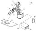
圖1是說明本實施方式所涉及的機器人視覺系統100的概要圖。如圖1所示,本實施方式的機器人視覺系統100構成為包括機器人110及控制部120。另外,控制部120與教導器140連接。教導器140是用於供用戶對機械臂114教導動作或進行手動操作的裝置。FIG. 1 is a schematic diagram illustrating a
機器人110具有支承臂114的主體部112,在臂114的前端安裝有末端執行器116。另外,在末端執行器116安裝有攝像機118。機器人110利用末端執行器116來保持工件104,並使該工件104移動至規定的位置。The
圖2是說明本實施方式的機器人視覺系統100的功能結構的功能框圖。如圖2所示,本實施方式的機器人視覺系統100構成為包括機器人110及控制部120。控制部120具有工件空間計算部122、臂移動部124、機器人座標取得部126、區域判斷部128、動作切換部130、攝像部132以及工件識別部134。FIG. 2 is a functional block diagram illustrating the functional configuration of the
作為預處理,工件空間計算部122計算工件104在工作台106上可能存在的範圍即工件空間108。詳細來說,對工作台106上載置工件104的場所進行各種改變並進行多次拍攝,或在工作台106上載置多個工件104並進行拍攝,由此能夠根據該攝像資料來設定工件空間108。As preprocessing, the workpiece
圖3是說明本實施方式的機器人視覺系統100的動作的流程圖。此外,在本實施方式中,以機器人110的末端執行器116從工件空間108外向工件空間108內移動為前提來進行說明。FIG. 3 is a flowchart illustrating the operation of the
在處理開始時機器人110的末端執行器116位於工件空間外的情況下,控制部120的臂移動部124通過教導動作來使機器人110的臂114及末端執行器116按照規定的程式進行動作(S202)。When the
接著,機器人座標取得部126取得末端執行器116的機器人座標(S204)。區域判斷部128參照工件空間計算部122中的工件空間108以及機器人座標取得部126得到的機器人座標,來判斷機器人110的末端執行器116是否位於工件空間108內(S206)。在末端執行器116位於工件空間108外的情況下(S206的“否”),控制部120重複進行S202-S206的處理。Next, the robot
在機器人110的末端執行器116位於工件空間108內的情況下(S206的“是”),動作切換部130將機器人110的動作從教導動作切換為視覺回饋動作(S208)。然後,控制部120的臂移動部124使機器人110的臂114及末端執行器116以視覺回饋動作來進行動作(S212)。When the
在視覺回饋動作時,控制部120的攝像部132使用攝像機118來拍攝圖像。然後,若工件識別部134在圖像內識別到工件104(物體識別),則臂移動部124使機器人110的末端執行器116移動至工件104,並利用末端執行器116來保持工件104。During the visual feedback operation, the
在切換為視覺回饋動作之後(S206~S212),返回到機器人座標取得步驟(S204)。然後,持續監視並判斷機器人110的末端執行器116的當前位置是否在工件空間108內(S206)。由此,在機器人110的末端執行器116從工件空間108內移動到工件空間108外的情況下,動作切換部130能夠將機器人110的動作從視覺回饋動作切換為教導動作。After switching to the visual feedback action (S206-S212), return to the robot coordinate acquisition step (S204). Then, it continuously monitors and judges whether the current position of the
如上述所說明的那樣,在本實施方式的機器人視覺系統100中,預先設定工件104可能存在的範圍即工件空間108。而且,當機器人的末端執行器116移動至工件空間108內時,機器人110的動作被從教導動作切換為視覺回饋動作。由此,通過教導動作來使末端執行器116高效地移動至工件空間108,當末端執行器116移動到了工件空間108時,變為精密地控制末端執行器116的視覺回饋動作。因而,能夠可靠且迅速地保持工件104,能夠實現作業效率的進一步提高。As described above, in the
以上參照附圖說明了本發明的優選的實施方式,但是本發明不限定於上述的例子,這是不言而喻的。如果是本領域技術人員,則明確可知的是,能夠在權利要求書所記載的範疇內想到各種變更例或修正例,並且應理解這些變更例或修正例當然也屬於本發明的技術範圍。 [產業方面的利用性]Preferred embodiments of the present invention have been described above with reference to the drawings, but it goes without saying that the present invention is not limited to the above examples. Those skilled in the art will clearly understand that various changes or corrections can be conceived within the scope described in the claims, and it should be understood that these changes and corrections naturally also belong to the technical scope of the present invention. [Industrial Utilization]
本發明能夠用作包括具有攝像機的機器人的機器人視覺系統。The present invention can be used as a robot vision system including a robot with a camera.
100…機器人視覺系統;104…工件;106…工作台;108…工件空間;110…機器人;112…主體部;114…臂;116…末端執行器;118…攝像機;120…控制部;122…工件空間計算部;124…臂移動部;126…機器人座標取得部;128…區域判斷部;130…動作切換部;132…攝像部;134…工件識別部;140…教導器。100…robot vision system; 104…workpiece; 106…workbench; 108…workpiece space; 110…robot; 112…main body; 114…arm; 116…end effector; 118…camera; 120…control unit; 122… 124...arm moving part; 126...robot coordinate acquisition part; 128...area judging part; 130...action switching part;
圖1是說明本實施方式所涉及的機器人視覺系統的概要圖。 圖2是說明本實施方式的機器人視覺系統的功能結構的功能框圖。 圖3是說明本實施方式的機器人視覺系統的動作的流程圖。FIG. 1 is a schematic diagram illustrating a robot vision system according to the present embodiment. FIG. 2 is a functional block diagram illustrating the functional configuration of the robot vision system according to the present embodiment. FIG. 3 is a flowchart illustrating the operation of the robot vision system according to the present embodiment.
S202:教導動作S202: Teaching actions
S204:機器人座標取得步驟S204: Steps for obtaining robot coordinates
S206:判斷末端執行器是否位於工件空間內的步驟S206: a step of judging whether the end effector is located in the workpiece space
S208:切換動作S208: switch action
S212:視覺回饋動作S212: Visual feedback action
Claims (1)
Translated fromChineseApplications Claiming Priority (2)
| Application Number | Priority Date | Filing Date | Title |
|---|---|---|---|
| JP2021114391AJP7054036B1 (en) | 2021-07-09 | 2021-07-09 | Robot vision system |
| JP2021-114391 | 2021-07-09 |
Publications (2)
| Publication Number | Publication Date |
|---|---|
| TW202302304A TW202302304A (en) | 2023-01-16 |
| TWI798099Btrue TWI798099B (en) | 2023-04-01 |
Family
ID=81260117
Family Applications (1)
| Application Number | Title | Priority Date | Filing Date |
|---|---|---|---|
| TW111120596ATWI798099B (en) | 2021-07-09 | 2022-06-02 | Robot Vision System |
Country Status (4)
| Country | Link |
|---|---|
| JP (1) | JP7054036B1 (en) |
| CN (1) | CN114589699A (en) |
| TW (1) | TWI798099B (en) |
| WO (1) | WO2023282032A1 (en) |
Families Citing this family (1)
| Publication number | Priority date | Publication date | Assignee | Title |
|---|---|---|---|---|
| WO2024228231A1 (en)* | 2023-05-01 | 2024-11-07 | 株式会社ニコン | Control system, robot system, control method, and computer program |
Citations (4)
| Publication number | Priority date | Publication date | Assignee | Title |
|---|---|---|---|---|
| JPH09311712A (en)* | 1996-05-21 | 1997-12-02 | Nippon Telegr & Teleph Corp <Ntt> | Robot control method and device |
| JP2012254518A (en)* | 2011-05-16 | 2012-12-27 | Seiko Epson Corp | Robot control system, robot system and program |
| JP2015085458A (en)* | 2013-10-31 | 2015-05-07 | セイコーエプソン株式会社 | Robot control device, robot system, and robot |
| JP2015174206A (en)* | 2014-03-18 | 2015-10-05 | セイコーエプソン株式会社 | Robot control device, robot system, robot, robot control method and robot control program |
Family Cites Families (8)
| Publication number | Priority date | Publication date | Assignee | Title |
|---|---|---|---|---|
| JP4249794B1 (en) | 2007-10-29 | 2009-04-08 | ファナック株式会社 | Control device for robot for workpiece transfer |
| JP2010131711A (en)* | 2008-12-05 | 2010-06-17 | Honda Motor Co Ltd | Method of controlling robot arm |
| JP2010152664A (en) | 2008-12-25 | 2010-07-08 | Nissei Corp | Sensorless motor-driven robot using image |
| US8600552B2 (en)* | 2009-10-30 | 2013-12-03 | Honda Motor Co., Ltd. | Information processing method, apparatus, and computer readable medium |
| JP5721167B2 (en) | 2010-11-26 | 2015-05-20 | 株式会社ダイヘン | Robot controller |
| JP2015136763A (en) | 2014-01-23 | 2015-07-30 | セイコーエプソン株式会社 | Control device, robot system, robot, and robot control method |
| JP6777670B2 (en)* | 2018-03-27 | 2020-10-28 | ファナック株式会社 | A robot system that uses image processing to correct robot teaching |
| CN110842928B (en)* | 2019-12-04 | 2022-02-22 | 中科新松有限公司 | Visual guiding and positioning method for compound robot |
- 2021
- 2021-07-09JPJP2021114391Apatent/JP7054036B1/enactiveActive
- 2022
- 2022-04-14CNCN202210393661.XApatent/CN114589699A/enactivePending
- 2022-06-02TWTW111120596Apatent/TWI798099B/enactive
- 2022-06-17WOPCT/JP2022/024366patent/WO2023282032A1/ennot_activeCeased
Patent Citations (4)
| Publication number | Priority date | Publication date | Assignee | Title |
|---|---|---|---|---|
| JPH09311712A (en)* | 1996-05-21 | 1997-12-02 | Nippon Telegr & Teleph Corp <Ntt> | Robot control method and device |
| JP2012254518A (en)* | 2011-05-16 | 2012-12-27 | Seiko Epson Corp | Robot control system, robot system and program |
| JP2015085458A (en)* | 2013-10-31 | 2015-05-07 | セイコーエプソン株式会社 | Robot control device, robot system, and robot |
| JP2015174206A (en)* | 2014-03-18 | 2015-10-05 | セイコーエプソン株式会社 | Robot control device, robot system, robot, robot control method and robot control program |
Also Published As
| Publication number | Publication date |
|---|---|
| WO2023282032A1 (en) | 2023-01-12 |
| CN114589699A (en) | 2022-06-07 |
| JP7054036B1 (en) | 2022-04-13 |
| JP2023010327A (en) | 2023-01-20 |
| TW202302304A (en) | 2023-01-16 |
Similar Documents
| Publication | Publication Date | Title |
|---|---|---|
| US11090814B2 (en) | Robot control method | |
| CN108942880B (en) | Robot system | |
| JP4249794B1 (en) | Control device for robot for workpiece transfer | |
| CN100561491C (en) | Method and device for automatic path learning | |
| CN108500979B (en) | Robot grabbing method and system based on camera communication connection | |
| JP6450960B2 (en) | Robot, robot system and teaching method | |
| US20180215035A1 (en) | Robot and method of controlling the same | |
| JP2009148845A (en) | Small-size production equipment | |
| JP2003211381A (en) | Robot controller | |
| US11345036B2 (en) | Robot control device, robot control system, and robot control method | |
| TWI798099B (en) | Robot Vision System | |
| JP2017124470A (en) | Robot and robot system | |
| JPS61204705A (en) | Orthogonal coordinate system setting system for robot | |
| CN114074331A (en) | Disordered grabbing method based on vision and robot | |
| WO2023102647A1 (en) | Method for automated 3d part localization and adjustment of robot end-effectors | |
| CN114670189A (en) | Storage medium, and method and system for generating control program of robot | |
| JP2018122376A (en) | Image processing device, robot control device, and robot | |
| WO2018214156A1 (en) | Method of correcting locomotion control command of robot, and related apparatus for same | |
| CN113878578A (en) | Dynamic self-adaptive positioning method and system suitable for composite robot | |
| CN114434440A (en) | Fitting method and robot system | |
| JP2022086463A (en) | Robot control device | |
| JP2018015856A (en) | Robot, robot controller, and robot system | |
| JP2007331075A (en) | Object gripping system and object gripping method for mobile work robot | |
| JP2020199610A (en) | Manual operation of robot arm | |
| JP2020163551A (en) | Control method and robot system |