TWI798040B - Needle guidance device - Google Patents
Needle guidance deviceDownload PDFInfo
- Publication number
- TWI798040B TWI798040BTW111112362ATW111112362ATWI798040BTW I798040 BTWI798040 BTW I798040BTW 111112362 ATW111112362 ATW 111112362ATW 111112362 ATW111112362 ATW 111112362ATW I798040 BTWI798040 BTW I798040B
- Authority
- TW
- Taiwan
- Prior art keywords
- pin
- sliding module
- slide rail
- needle
- sliding
- Prior art date
Links
- 239000000523sampleSubstances0.000claimsabstractdescription60
- 238000001514detection methodMethods0.000claimsdescription15
- 244000273256Phragmites communisSpecies0.000claimsdescription6
- 235000014676Phragmites communisNutrition0.000claimsdescription6
- 238000002604ultrasonographyMethods0.000abstractdescription6
- 238000010586diagramMethods0.000description17
- 210000000481breastAnatomy0.000description5
- 238000001356surgical procedureMethods0.000description5
- 230000000694effectsEffects0.000description4
- 238000001574biopsyMethods0.000description3
- 230000003287optical effectEffects0.000description2
- 238000003384imaging methodMethods0.000description1
- 230000006698inductionEffects0.000description1
- 238000002347injectionMethods0.000description1
- 239000007924injectionSubstances0.000description1
- 238000003780insertionMethods0.000description1
- 230000037431insertionEffects0.000description1
- 238000009434installationMethods0.000description1
- 230000003993interactionEffects0.000description1
- 238000010330laser markingMethods0.000description1
- 238000012986modificationMethods0.000description1
- 230000004048modificationEffects0.000description1
- 239000000243solutionSubstances0.000description1
Images


Landscapes
- Details Of Garments (AREA)
- Sewing Machines And Sewing (AREA)
- Ultra Sonic Daignosis Equipment (AREA)
Abstract
Description
Translated fromChinese一種針具引導裝置,特別是應用於超音波引導手術的針具引導裝置。A needle guiding device, in particular a needle guiding device applied to ultrasonic guided surgery.
徒手超音波引導手術是一種常用的手術,經常應用於組織活檢術(Biopsy),例如乳房組織切片。在實施時,需要操作人員一手操作超音波探頭,另一手操作探針刺入乳房,對於操作者的手眼協調能力非常要求。同時,超音波探測屬於二維探測,操作者需要盡量確保探針與探測垂直平面重合,才能確切掌握探針的位置,大大提高了操作的難度。Manual ultrasound-guided surgery is a commonly used surgery, often applied to tissue biopsy (Biopsy), such as breast tissue section. During implementation, the operator is required to operate the ultrasonic probe with one hand and the probe to penetrate the breast with the other hand, which requires the operator's hand-eye coordination ability very much. At the same time, ultrasonic detection is a two-dimensional detection. The operator needs to ensure that the probe coincides with the vertical plane of the detection as much as possible to accurately grasp the position of the probe, which greatly increases the difficulty of operation.
目前可見幾種技術手段嘗試解決上述問題,例如:At present, several technical means can be seen to try to solve the above problems, such as:
1.側邊附著式引導裝置:如Civco-Ultrasound Needle Guides產品線,該類型以塑膠件作為主體,配合扣件依附在超音波探頭上。透過搭配針尺寸的管狀零件,使針在穿刺過程中保持與超音波掃描平面共平面。然而,其缺點是,入針瞬間難以觀察到刺入皮膚的入針點,角度設定好後無法再更改,對於較軟的組織部位(如乳房)來說,可活動範圍過低。1. Side-attached guide device: such as the Civco-Ultrasound Needle Guides product line, this type uses plastic parts as the main body, and is attached to the ultrasonic probe with fasteners. By matching the tubular part with the needle size, the needle is kept coplanar with the ultrasonic scanning plane during the puncture. However, its disadvantage is that it is difficult to observe the point where the needle penetrates the skin at the moment of needle insertion, and the angle cannot be changed after it is set, and the movable range is too low for softer tissue parts (such as breasts).
2.連桿式機構:如Jackrit Suthakorn,Narucha Tanaiutchawoot,Cholatip Wiratkapan & Songpol Ongwattanakul(2018),Breast biopsy navigation system with an assisted needle holder tool and 2D graphical user interface,European Journal of Radiology Open Volume 5,2018,Pages 93-101,(doi:10.1016/j.ejro.2018.07.001)所示,運用兩連桿以及卡扣使針在穿刺過程中保持與超音波掃描平面共平面。然而,其缺點是,沒有旋轉角度的約束、桿件位置可能會是視線屏蔽,塑膠扣件的穩定性未知,可能出現平面偏移。2. Linkage mechanism: such as Jackrit Suthakorn, Narucha Tanaiutchawoot, Cholatip Wiratkapan & Songpol Ongwattanakul (2018), Breast biopsy navigation system with an assisted needle holder tool and 2D graphical user interface, European Journal of Radiology Open Volume 5, 2018, 93-101, (doi: 10.1016/j.ejro.2018.07.001), using two connecting rods and buckles to keep the needle coplanar with the ultrasonic scanning plane during puncture. HoweverHowever, its disadvantages are that there is no constraint on the rotation angle, the position of the rod may be a line of sight shield, the stability of the plastic fastener is unknown, and there may be a plane offset.
3.雷射標記輔助:如Eric Chiwei Shiao & Po-Ling Kuo(2019),Two-Dimensional Laser-Align Device for Ultrasound-Guided Injection,J.Clin.Med.,Volume 8,Issue 7(July 2019)(doi:10.3390/jcm8071048)所示,在超音波探頭上加裝平面雷射裝置,以投射出一條與超音波掃描平面共平面的雷射線段在外部,提供使用者對齊入針平面。然而,其缺點是,無實際物理約束,需耗神在對齊雷射線段與針之間。對於活動性較高的部位來說,表面不夠平坦會使得雷射線段失真。3. Laser marking assistance: such as Eric Chiwei Shiao & Po-Ling Kuo(2019), Two-Dimensional Laser-Align Device for Ultrasound-Guided Injection, J.Clin.Med., Volume 8, Issue 7(July 2019)( As shown in doi: 10.3390/jcm8071048), a planar laser device is installed on the ultrasonic probe to project a laser line segment coplanar with the ultrasonic scanning plane on the outside, providing users with alignment to the needle entry plane. However, the disadvantage is that there is no real physical constraint, and effort is required to align the ray line segment with the needle. For areas of high activity, the surface is not flat enough to distort the segment of the laser line.
4.光學定位系統、磁感定位系統:如Brainlab-Ultrasound Navigation產品線,較先進、高科技的產品線,利用光學空間定位或是磁場空間定位去獲得針在空間中的絕對位置。搭配三視圖的術中成像可以讓醫師準確掌握手術針與目標之間的空間關係。然而,其缺點是,造價十分昂貴,要求全套的整合性高級儀器,需要大量的前置作業。通常用於腦神經外科手術,對於需要大量快速的乳房外科切片而言不是好選擇。4. Optical positioning system, magnetic induction positioning system: such as the Brainlab-Ultrasound Navigation product line, more advanced and high-tech product lines, use optical space positioning or magnetic field space positioning to obtain the absolute position of the needle in space. Intraoperative imaging with three views allows doctors to accurately grasp the spatial relationship between the surgical needle and the target. However, its disadvantage is that it is very expensive, requires a full set of integrated advanced instruments, and requires a lot of pre-work. Typically used for neurosurgery, not a good choice for breast surgery requiring a large number of rapid slices.
綜上所述,目前未有良好且低成本的解決方案,因此如何解決上述問題便是對於本領域具通常知識者是值得去思量的。To sum up, there is no good and low-cost solution at present, so how to solve the above problems is worth considering for those skilled in the art.
本發明之目的在於提供一種針具引導裝置,可以讓針具與超音波探頭的探測垂直平面重合,可精確地掌握針具的位置,大幅降低操作人員的手眼協調要求,並具備使用簡單、成本較低的優點。其具體技術手段如下:一種針具引導裝置,設置於一超音波探頭上,並且適於固定一針具,該針具引導裝置包括一探頭端結構、一第一滑軌、一第一滑動模組、一第二滑動模組、一第二滑軌及一夾具。第一滑軌其中一端設置於該探頭端結構上。第一滑動模組套設於該第一滑軌上,第一滑動模組包括一第一基座,該第一基座包括多個第一接合磁鐵、多個第一定位孔洞及多個第一定位結構。第二滑動模組與該第一滑動模組相連接,該第二滑動模組包括一第二基座,該第二基座包括多個第二接合磁鐵、多個第二定位孔洞及多個第二定位結構。第二滑軌穿過該第二滑動模組而設置。夾具設置於該第二滑軌上,並適於固定該針具,該針具與該超音波探頭的一探測垂直平面重合。其中,該第一定位孔洞與該第二定位孔洞為弧形孔洞。其中,該第一滑動模組與該第二滑動模組以一角度差相連接,並且該第一定位結構穿過該第二定位孔洞,該第二定位結構穿過該第一定位孔洞,該第一接合磁鐵與該第二接合磁鐵互相吸附。The purpose of the present invention is to provide a needle guiding device, which can make the needle and the detection vertical plane of the ultrasonic probe coincide, can accurately grasp the position of the needle, greatly reduce the operator's hand-eye coordination requirements, and has the advantages of simple use, low cost Lower merit. Its specific technical means are as follows: a needle guiding device is arranged on an ultrasonic probe and is suitable for fixing a needle, the needle guiding device includes a probe end structure, a first slide rail, a first sliding mold group, a second sliding modegroup, a second slide rail and a fixture. One end of the first sliding rail is arranged on the probe end structure. The first sliding module is sleeved on the first sliding rail, the first sliding module includes a first base, and the first base includes a plurality of first joint magnets, a plurality of first positioning holes and a plurality of first positioning holes. A positioning structure. The second sliding module is connected with the first sliding module, the second sliding module includes a second base, and the second base includes a plurality of second bonding magnets, a plurality of second positioning holes and a plurality of Second positioning structure. The second slide rail is arranged through the second slide module. The fixture is arranged on the second sliding rail and is suitable for fixing the needle, and the needle coincides with a detection vertical plane of the ultrasonic probe. Wherein, the first positioning hole and the second positioning hole are arc-shaped holes. Wherein, the first sliding module is connected with the second sliding module with an angle difference, and the first positioning structure passes through the second positioning hole, the second positioning structure passes through the first positioning hole, the The first joint magnet and the second joint magnet are attracted to each other.
如上述之針具引導裝置,其中,該夾具還包括一第一結構、一第二結構與多個夾具固定元件。第一結構包括一滑軌凹槽及一第一夾持部。滑軌凹槽包覆該第二滑軌的側邊。第二結構包括一第二夾持部。夾具固定元件穿過該第一結構、該第二結構與該第二滑軌而設置。As in the above-mentioned needle guiding device, wherein the clamp further includes a first structure, a second structure and a plurality of clamp fixing elements. The first structure includes a slide rail groove and a first clamping portion. The slide rail groove covers the side of the second slide rail. The second structure includes a second clamping portion. The clamp fixing element is disposed through the first structure, the second structure and the second slide rail.
如上述之針具引導裝置,其中,該第二滑軌上還包括多個夾具孔洞。In the above-mentioned needle guiding device, the second slide rail further includes a plurality of clamp holes.
如上述之針具引導裝置,其中,該固定元件為螺絲。As in the above-mentioned needle guiding device, wherein the fixing element is a screw.
如上述之針具引導裝置,其中,該探頭端結構還包括多個卡槽,所述卡槽為垂直排列設置於該探頭端結構上,所述卡槽的延伸方向彼此平行,該第一滑軌是設置於該卡槽中。As in the above-mentioned needle guide device, wherein the probe end structure further includes a plurality of slots, the slots are vertically arranged on the probe end structure, the extension directions of the slots are parallel to each other, and the first slide The rail is arranged in the card slot.
如上述之針具引導裝置,其中,該探頭端結構是圍繞該超音波探頭而設置。As in the above-mentioned needle guiding device, wherein, the probe end structure is arranged around the ultrasonic probe.
如上述之針具引導裝置,其中,該第一滑動模組還包括一第一滑動塊,包覆該第一滑軌的側面,使該第一滑動模組能夠在該第一滑軌上移動;該第二滑動模組還包括一第二滑動塊,包覆該第二滑軌的側面,使該第二滑動模組能夠在該第二滑軌上移動。As in the above-mentioned needle guide device, wherein, the first sliding module further includes a first sliding block covering the side of the first sliding rail so that the first sliding module can move on the first sliding rail ; The second sliding module also includes a second sliding block covering the side of the second sliding rail, so that the second sliding module can move on the second sliding rail.
如上述之針具引導裝置,其中,該第一基座還包括多個第一固定孔洞與多個第一插銷孔洞。其中,該第二基座還包括多個第二固定孔洞與多個第二插銷孔洞。其中,該第一滑動模組還包括一第一按鈕機構,設置於該第一基座上,該第一按鈕機構包括一第一主體及多個第一插銷。第一主體設置有一第一固定磁鐵。第一插銷設置於該第一主體上,並且穿過該第一基座上的該第一插銷孔洞。其中,第二滑動模組還包括一第二按鈕機構,設置於該第二基座上,該第二按鈕機構包括一第二主體及多個第二插銷。第二主體設置有一第二固定磁鐵。第二插銷設置於該第二主體上,並且穿過該第二基座上的該第二插銷孔洞。其中,當該第一按鈕機構被按壓,該第一按鈕機構往該第二滑動模組方向移動,並且該第一插銷穿過該第二固定孔洞,該第一按鈕機構的該第一主體與該第一滑軌接觸,該第一固定磁鐵與該第一滑軌吸附。其中,當該第二按鈕機構被按壓,該第二按鈕機構往該第一滑動模組方向移動,並且該第二插銷穿過該第一固定孔洞,該第二按鈕機構的該第二主體與該第二滑軌接觸,該第二固定磁鐵與該第二滑軌吸附。In the above-mentioned needle guiding device, the first base further includes a plurality of first fixing holes and a plurality of first pin holes. Wherein, the second base further includes a plurality of second fixing holes and a plurality of second pin holes. Wherein, the first sliding module further includes a first button mechanism disposed on the first base, and the first button mechanism includes a first main body and a plurality of first pins. The first body is provided with a first fixed magnet. The first pin is disposed on the first body and passes through the first pin hole on the first base. Wherein, the second sliding module further includes a second button mechanism, which is arranged on the second base, and the second button mechanism includes a second main body and a plurality of second latches. The second body is provided with a second fixed magnet. The second pin is disposed on the second body and passes through the second pin hole on the second base. Wherein, when the first button mechanism is pressed, the first button mechanism moves toward the direction of the second sliding module, and the first pin passes through the second fixing hole, the first body of the first button mechanism and the The first slide rail is in contact, and the first fixed magnet is attracted to the first slide rail. Wherein, when the second button mechanism is pressed, the second button mechanism moves toward the direction of the first sliding module, and the second pin passes through the first fixing hole, the second body of the second button mechanism and The second slide rail is in contact, and the second fixed magnet is attracted to the second slide rail.
如上述之針具引導裝置,其中,該第一固定孔洞與該第二固定孔洞與為弧形孔洞。As in the above-mentioned needle guiding device, wherein, the first fixing hole and the second fixing hole are arc-shaped holes.
如上述之針具引導裝置,其中,該第一插銷與該第二插銷還分別包括一插銷固定元件,該第一插銷與該第二插銷經由各自的該插銷固定元件而分別與該第二固定孔洞及該第一固定孔洞形成緊配合。As in the above-mentioned needle guide device, wherein, the first pin and the second pin further include a pin fixing element, and the first pin and the second pin are respectively fixed to the second pin through the respective pin fixing elements. The hole and the first fixing hole form a tight fit.
如上述之針具引導裝置,其中,該插銷固定元件包括多個簧片,這些簧片沿著該第一插銷或該第二插銷的徑向向外膨脹。As in the above-mentioned needle guiding device, wherein the pin fixing element includes a plurality of reeds, and these reeds expand outward along the radial direction of the first pin or the second pin.
10:超音波探頭10: Ultrasonic probe
11:探測水平平面11: Detection of horizontal plane
100:針具引導裝置100: Needle guide device
110:探頭端結構110: Probe end structure
111:卡槽111: card slot
120:第一滑軌120: The first slide rail
130:第一滑動模組130: The first sliding module
131:第一基座131: The first base
1311、1311a、1311b:第一接合磁鐵1311, 1311a, 1311b: first engagement magnet
1311’:凹槽1311': Groove
1312:第一定位孔洞1312: The first positioning hole
1313:第一固定孔洞1313: The first fixed hole
1314:第一插銷孔洞1314: The first pin hole
1315:第一定位結構1315: The first positioning structure
132:第一按鈕機構132: First button mechanism
1321:第一主體1321: The first subject
1322:第一插銷1322: The first pin
1323:第一固定磁鐵1323: The first fixed magnet
133:第一限制機構133: First Restricted Agency
134:第一滑動塊134: The first slider
140:第二滑動模組140: Second sliding module
141:第二基座141: Second base
1411、1411a、1411b:第二接合磁鐵1411, 1411a, 1411b: second engagement magnet
1411’:凹槽1411': Groove
1412:第二定位孔洞1412: The second positioning hole
1413:第二固定孔洞1413: The second fixed hole
1414:第二插銷孔洞1414: Second pin hole
1415:第二定位結構1415: Second positioning structure
142:第二按鈕機構142: Second button mechanism
1421:第二主體1421: the second subject
1422:第二插銷1422: Second pin
1423:第二固定磁鐵1423: second fixed magnet
143:第二限制機構143:Second restrictive agency
144:第二滑動塊144: the second sliding block
150:第二滑軌150: Second slide rail
151:夾具固定孔洞151: Clamp fixing hole
160:夾具160: fixture
161:第一結構161: The first structure
1611:第一夾持部1611: the first clamping part
1612:滑軌凹槽1612: Rail groove
162:第二結構162: Second structure
1621:第二夾持部1621: the second clamping part
163:夾具固定元件163: clamp fixing element
170:插銷固定元件170: bolt fixing element
20:針具20: Needle
21:延伸方向21: Extension direction
31、32、33:方向31, 32, 33: direction
θ:角度差θ: angle difference
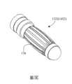
圖1所繪示為本發明之針具引導裝置示意圖。FIG. 1 is a schematic diagram of a needle guiding device of the present invention.
圖2所繪示為部分的針具引導裝置示意圖。FIG. 2 is a schematic diagram of a part of the needle guiding device.
圖3A與圖3B所繪示為第一滑動模組與第二滑動模組的示意圖。3A and 3B are schematic views of the first sliding module and the second sliding module.
圖3C所繪示為第一滑動模組與第二滑動模組連接的示意圖。FIG. 3C is a schematic diagram of the connection between the first sliding module and the second sliding module.
圖3D所繪示為第一滑動模組與第二滑動模組相連接後的示意圖。FIG. 3D is a schematic diagram of the connection between the first sliding module and the second sliding module.
圖3E所繪示為插銷固定元件的示意圖。FIG. 3E is a schematic diagram of the pin fixing element.
圖3F與圖3G所繪示為第一按鈕機構或第二按鈕機構被壓按時之示意圖。FIG. 3F and FIG. 3G are schematic diagrams when the first button mechanism or the second button mechanism is pressed.
圖3H所繪示為第一接合磁鐵與第二接合磁鐵的設置示意圖。FIG. 3H is a schematic diagram showing the arrangement of the first joint magnet and the second joint magnet.
圖4A與圖4B所繪示為夾具的示意圖。4A and 4B are schematic diagrams of the jig.
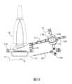
圖5A所繪示為本發明針具引導裝置的側面示意圖。FIG. 5A is a schematic side view of the needle guiding device of the present invention.
圖5B所繪示為探測垂直平面的示意圖。FIG. 5B is a schematic diagram of detecting a vertical plane.
圖5C所繪示為針具與超音波探頭的仰視示意圖。FIG. 5C is a schematic bottom view of the needle and the ultrasonic probe.
請參閱圖1,圖1所繪示為本發明之針具引導裝置示意圖。本發明之針具引導裝置100是裝置在一超音波探頭10上,並且適於固定一針具20。超音波探頭10為超音波探測的探測頭,適於與患者的皮膚接觸。而針具20則是引導採檢探針的裝置,探針可由針具20伸出並刺穿患者皮膚。而本發明之針具引導裝置100能夠使針具20與超音波探頭10保持一個固定的角度差。Please refer to FIG. 1 . FIG. 1 is a schematic view of the needle guiding device of the present invention. The
本發明之針具引導裝置100包括一探頭端結構110、一第一滑軌120、一第一滑動模組130、一第二滑動模組140、一第二滑軌150與一夾具160。其中,探頭端結構110是與超音波探頭10相連接。具體來說,探頭端結構110是圍繞設置在超音波探頭10上。並且,探頭端結構110上還包括多個卡槽111,而第一滑軌120則連接於其中一個卡槽111上。進一步來說,卡槽111的延伸方向與超音波探頭10的一探測水平平面11具有一角度差θ(如圖5A所示),多個卡槽111為垂直排列設置於探頭端結構110上,並且每個卡槽111的延伸方向彼此平行。如此一來,設置於卡槽111上的第一滑軌120也跟超音波探頭10的一探測面也具有角度差θ。進一步來說,第一滑軌120的側面具有凹下的結構,可與第一滑動模組130中的第一滑動塊134(如圖2所示)相配合,避免第一滑動模組130從第一滑軌120上脫落。The
請參閱圖2,圖2所繪示為部分的針具引導裝置示意圖。第一滑動模組130是套設在第一滑軌120上,並可在第一滑軌120上移動。而第二滑動模組140則與第一滑動模組130相連接,第二滑軌150穿過第二滑動模組140而設置。進一步來說,第一滑動模組130與第二滑動模組140具有相同的特徵,並以不同的設置角度相連接,以下說明第一滑動模組130與第二滑動模組140的特徵與連接方式。Please refer to FIG. 2 , which is a schematic diagram of a part of the needle guiding device. The
請參閱圖3A、圖3B與圖3C,圖3A與圖3B所繪示為第一滑動模組與第二滑動模組的示意圖,圖3C所繪示為第一滑動模組與第二滑動模組連接的示意圖。由於第一滑動模組130與第二滑動模組140具有相同的技術特徵,但為明確說明第一滑動模組130與第二滑動模組140的連接與互動關係,仍使用不同的名稱與符號標示,在圖3A與圖3B中,括號外的符號對應第一滑動模組130,括號內的符號則對應第二滑動模組140。首先針對第一滑動模組130說明,請參照圖3A與圖3B中括號外的符號,第一滑動模組130包括一第一基座131、一第一按鈕機構132與一第一限制機構133。第一按鈕機構132設置在第一基座131上,而第一限制機構133覆蓋部分的第一按鈕機構132並與第一基座131相連接,第一限制機構133可避免第一按鈕機構132從第一基座131上脫離。Please refer to FIG. 3A, FIG. 3B and FIG. 3C, FIG. 3A and FIG. 3B are schematic diagrams of the first sliding module and the second sliding module, and FIG. 3C shows the first sliding module and the second sliding module. Schematic diagram of group connections. Since the first sliding
第一基座131上包括了多個第一接合磁鐵1311、多個第一定位孔洞1312、多個第一固定孔洞1313、多個第一插銷孔洞1314與多個第一定位結構1315。第一接合磁鐵1311設置在第一基座131上。具體來說,第一基座131上還具有與第一接合磁鐵1311數量相當的凹槽1311’(參閱圖3B),這些凹槽1311’的開口是面向第一按鈕機構132而設置,而第一接合磁鐵1311便設置在這些凹槽1311’中。The
第一定位孔洞1312、第一固定孔洞1313與第一插銷孔洞1314設置在第一基座131上,並且是貫穿第一基座131。其中,第一定位孔洞1312與第一固定孔洞1313為弧形孔洞,並且是以第一基座131中心點為圓心而形成的弧形孔洞,而第一固定孔洞1313大於第一定位孔洞1312,弧形孔洞之功效容後再述。第一插銷孔洞1314設置在第一基座131的邊緣處,進一步來說,第一插銷孔洞1314是對應第一按鈕機構132上的第一插銷1322而設置。The
第一定位結構1315(如圖3C所示)是設置在第一基座131上,並且是設置在相對於第一固定接合磁鐵1311的另一面上,也就是說第一接合磁鐵1311與第一定位結構1315是分別設置在不同的面上。第一定位結構1315是一種圓柱結構,並從第一基座131上凸起。The first positioning structure 1315 (as shown in FIG. 3C ) is arranged on the
在一實施例中,是以螺絲釘設置於第一基座131上以形成第一定位結構1315,並且第一定位結構1315的數量與第一定位孔洞1313相同。此外,在此實施例中,第一滑動塊134上具有與第一定位結構1315相對應的螺牙孔,因此,第一定位結構1315是貫穿第一基座131並鎖入第一滑動塊134,將第一滑動塊134固定在第一基座上。In one embodiment, screws are disposed on the
第一按鈕機構132包括了一第一主體1321與多個第一插銷1322,在本實施例中,第一主體1321為一長形結構,第一插銷1322為兩個,分別設置於第一主體1321的兩個端點,第一主體1321與第一插銷1322使第一按鈕機構132從側邊看略呈C字型的形狀。此外,第一插銷1322會穿過第一插銷孔洞1314。當第一滑軌120與第一滑動模組130相組合時,第一滑軌120會從第一按鈕機構132的第一主體1321下方與兩個第一插銷1322的中間所界定的空間穿過。The
第一主體1321上還設置有一第一固定磁鐵1323,當第一按鈕機構132被按壓,第一按鈕機構132往第一滑軌120移動並接觸,第一固定磁鐵1323便會吸附第一滑軌120,以產生固定作用,使第一滑動模組130無法在第一滑軌120上移動。在一實施例中,第一滑動模組130還包括一第一滑動塊134,包覆第一滑軌120的側面,使第一滑動模組130能夠在第一滑軌120上移動。具體來說,第一滑動塊134設置在第一基座131上,且第一滑動塊134具有與第一滑軌120側面形狀相符的結構,藉此包覆第一滑軌120的側面,以讓第一滑動模組130可經由第一滑動塊134在第一滑軌120上移動。The
接下來針對第二滑動模組140說明,請參照圖3A與圖3B括號內的符號。第二滑動模組140包括一第二基座141、一第二按鈕機構142與一第二限制機構143。第二按鈕機構142設置在第二基座141上,而第二限制機構143覆蓋部分的第二按鈕機構142並與第二基座141相連接,第二限制機構143可避免第二按鈕機構142從第二基座141上脫離。Next, for the description of the second sliding
第二基座141上包括了多個第二接合磁鐵1411、多個第二定位孔洞1412、多個第二固定孔洞1413、多個第二插銷孔洞1414與多個第二定位結構1415。第二接合磁鐵1411設置在第二基座141上。具體來說,第二基座141上還具有與第二接合磁鐵1411數量相當的凹槽1411’(參閱圖3B),這些凹槽1411’的開口是面向第二按鈕機構142而設置,而第二接合磁鐵1411便設置在這些凹槽1411’中。The
第二定位孔洞1412、第二固定孔洞1413與第二插銷孔洞1414設置在第二基座141上,並且是貫穿第二基座141。其中,第二定位孔洞1412與第一固定孔洞1413為弧形孔洞,並且是以第二基座141中心點為圓心而形成的弧形孔洞。而第二固定孔洞1413大於第一固定孔洞1412,弧形孔洞之功效容後再述。第二插銷孔洞1414設置在第二基座141的邊緣處,進一步來說,第二插銷孔洞1414是與第二按鈕機構142上的第二插銷1422相對應。The
第二定位結構1415(如圖3C所示)是設置在第二基座141上,並且是設置在相對於第二固定接合磁鐵1411的另一面上,也就是說第二固定接合磁鐵1411與第一定位結構1415是分別設置在不同的面上。第二定位結構1415是一種圓柱結構,並從第二基座141上凸起。在一實施例中,是以螺絲釘設置於第二基座141上以形成第二定位結構1415,並且第二定位結構1415的數量與第二定位孔洞1412相同。The second positioning structure 1415 (as shown in FIG. 3C ) is arranged on the
第二按鈕機構142包括了一第二主體1421與多個第二插銷1422,在本實施例中,第二主體1421為一長形結構,第二插銷1422為兩個,分別設置於第二主體1421的兩個端點,第二主體1421與第二插銷1422使第二按鈕機構142從側邊看略呈C字型的形狀。此外,第二插銷1422會穿過第二插銷孔洞1414。當第二滑軌150與第二滑動模組140相組合時,第二滑軌150會從第二按鈕機構142的第二主體1421下方與兩個第二插銷1422的中間所界定的空間穿過。The
第二主體1421上還設置有一第二固定磁鐵1423,當第二按鈕機構142被按壓,第二按鈕機構142往第二滑軌150移動並接觸,第二固定磁鐵1423便會吸附第二滑軌150,以產生固定作用,使第二滑動模組140無法在第二滑軌150上移動。在一實施例中,第二滑動模組140還包括一第二滑動塊144,包覆第二滑軌150的側面,使第二滑動模組140能夠在第二滑軌150上移動。具體來說,第二滑動塊144設置在第二基座141上,且第二滑動塊144具有與第二滑軌150側面相符的凸起結構,藉此包覆第二滑軌150的側面以讓第二滑動模組140可經由第二滑動塊144在第二滑軌150上移動。The second
請參閱圖3C,第一滑動模組130與第二滑動模組140相連接,並且是由第一動模組130的第一基座131與第二滑動模組140的第二基座141相連接。進一步來說,第一滑動模組130與第二滑動模組140是以一角度差相連接。在本實施例中,此角度差為90度。Please refer to Fig. 3C, the first sliding
請參閱圖3D,圖3D所繪示為第一滑動模組130與第二滑動模組140相連接後的示意圖。在圖3D中,僅繪出部分元件,以便說明其連接關係。相連接時,第一滑動模組130的第一定位結構1315穿過第二滑動模組140的第二定位孔洞1412,第二滑動模組140的第二定位結構1415穿過第一定位結構1315的第一定位孔洞1312,第一滑動模組130的第一接合磁鐵1311與第二滑動模組140的第二接合磁鐵1411互相磁吸而固定。Please refer to FIG. 3D . FIG. 3D is a schematic diagram of the connection between the first sliding
請參閱圖3H,圖3H所繪示為第一接合磁鐵1311與第二接合磁鐵1411的設置示意圖。在圖3H中,由於第一接合磁鐵1311與第二接合磁鐵1411分別設置在第一基座131與第二基座141上,從第一基座131與第二基座141接合處並無法直接看到第一接合磁鐵1311與第二接合磁鐵1411,故以虛線表示。在此實施例中,第一接合磁鐵1311與第二接合磁鐵1411分別為4個。並且設置時,其磁鐵的極性會交錯設置,例如第一接合磁鐵1311a會是S極面向第二滑動模組140,周邊右方與下方的第一接合磁鐵1311b則為N極面向第二滑動模組140。此外,與第一接合磁鐵1311a相對應的第二接合磁鐵1411b則為N極面向第一滑動模組130。如此在接合第一滑動模組130與第二滑動模組140時,可利用第一接合磁鐵1311與第二接合磁鐵1411的極性互相吸附,來確保第一滑動模組130與第二滑動模組140彼此垂直,並且利用同極性相斥避免第一滑動模組130與第二滑動模組140以錯誤角度接合。Please refer to FIG. 3H . FIG. 3H is a schematic view showing the arrangement of the first
相連接後,當第一按鈕機構132被按壓,第一按鈕機構132往第二滑動模組140方向移動,並且第一插銷1322穿過第二固定孔洞1413,第一按鈕機構132之第一主體1321與第一滑軌120接觸,第一固定磁鐵1323與第一滑軌120吸附,將第一滑動模組130固定在第一滑軌120上。After being connected, when the
當第二按鈕機構142被按壓,第二按鈕機構142往第一滑動模組130方向移動,並且第二插銷1422穿過第一固定孔洞1313,第二按鈕機構142之第二主體1421與第二滑軌150接觸,第二固定磁鐵1423與第二滑軌150吸附,將第二滑動模組140固定在第二滑軌150上。When the
請參閱圖3E至圖3G,圖3E所繪示為插銷固定元件170的示意圖。圖3F與圖3G所繪示為第一按鈕機構132或第二按鈕機構142被壓按時之示意圖。在一實施例中,第一插銷1322與第二插銷1422還分別包括多個插銷固定元件170,第一插銷1322與第二插銷1422各自經由該插銷固定元件170而分別與第二固定孔洞1413與第一固定孔洞1313形成緊配合。具體來說,插銷固定元件170還包括多個簧片,這些簧片沿著第一插銷1322或第二插銷1422的徑向向外膨脹。因此當第一按鈕機構132或第二按鈕機構142被壓按時(如圖3G),第一插銷1322插入第二固定孔洞1413後,插銷固定元件170與第二固定孔洞1413內緣緊貼,讓第一插銷1322與第二固定孔洞1413形成緊配合。當第二插銷1422插入第一固定孔洞1313後,插銷固定元件170與第一固定孔洞1313內緣緊貼,讓第二插銷1422與第一固定孔洞1313形成緊配合,如此一來便可將第一按鈕機構132固定於第一基座131上,將第二按鈕機構142固定在第二基座141上。Please refer to FIG. 3E to FIG. 3G , FIG. 3E is a schematic diagram of the
此外,插銷固定元件170並未涵蓋第一插銷1322或第二插銷1422的末端,因此在第一按鈕機構132或第二按鈕機構142未壓按時,僅有第一插銷1322或第二插銷1422的末端伸入第一固定孔洞1313或第二固定孔洞1412(參閱圖3F),此時第一插銷1322或第二插銷1422仍可在第一固定孔洞1313或第二固定孔洞1412中移動。In addition, the
在本實施例中,由於第一定位孔洞1312、第一固定孔洞1313、第二定位孔洞1412與第二固定孔洞1413為弧形孔洞,因此在第一滑動模組130與第二滑動模組140相接合後,可經由外力小幅度的旋轉第一滑動模組130或第二滑動模組140的角度。具體來說,是以第一滑動模組130或第二滑動模組140的中心為圓心進行旋轉,可旋轉的角度例如為25度。此時,第二定位結構1415可在第一定位孔洞1312內移動,第一定位結構1315可在第二定位孔洞1412內移動。第二插銷1422可在第一固定孔洞1313內移動,第一插銷1322可在第二固定孔洞1413內移動。此外,前述第一滑動模組130或第二滑動模組140的轉動角度並不限於25度,可因應不同需求而修改第一定位孔洞1312、第一固定孔洞1313、第二定位孔洞1412與第二固定孔洞1413的尺寸,以調整第一滑動模組130或第二滑動模組140的轉動角度。In this embodiment, since the
請參閱圖4A與圖4B。圖4A與圖4B所繪示為夾具的示意圖。夾具160是設置在第二滑軌150上,並且夾具160適於固定針具20。夾具160包括了一第一結構161、一第二結構162與多個夾具固定元件163。其中,第一結構161包括一第一夾持部1611與一滑軌凹槽1612。第一結構161的整體略為C字形結構,以形成第一夾持部1611,用以設置針具20。滑軌凹槽1612相對於第一夾持部1611而設置,並且包覆第二滑軌150的側面。Please refer to FIG. 4A and FIG. 4B. 4A and 4B are schematic diagrams of the jig. The
第二結構162的整體略為C字形結構,以形成第二夾持部1621。第二夾持部1621的開口與第一夾持部1611的開口相接合而設置,從而形成容納針具20的空間。夾具固定元件163則穿過第一結構161、第二結構162與第二滑軌150而設置,因此夾具固定元件163將第一結構161、第二結構162與第二滑軌150固定,使其無法在第二滑軌150上滑動,同時可將針具20穩固地固定在第二夾持部1621的開口與第一夾持部1611的開口上。在本實施例中,夾具固定元件163為螺絲。在一實施例中,第二滑軌150上還包括多個夾具孔洞151,夾具固定元件163是穿過夾具孔洞151將夾具160固定在第二滑軌150上。本發明針具引導裝置100的結構與元件說明如上,以下將說明針具引導裝置100的應用方式。The overall
請參閱圖5A至圖5C,圖5A所繪示為本發明針具引導裝置100的側面示意圖。圖5B所繪示為探測垂直平面的示意圖,圖5C所繪示為針具與超音波探頭的仰視示意圖。針具引導裝置100是經由探頭端結構110設置在超音波探頭10上。此時第一滑軌120可選擇安裝在其中一個卡槽111上,藉此可調整針具20的垂直位置。進一步來說,第一滑動模組130則可在第一滑軌120上移動,即沿著方向31移動,藉此移動針具20的水平位置。同時移動第二滑軌150上移動,即第二滑軌150可沿著方向32移動,調整針具20的垂直位置。還能夠旋轉第二滑動模組140,便可在方向33上調整第二滑軌150的角度。透過上述方向31、32與33的調整針具20的方向,針具20的方向確認,即可壓按第一按鈕機構132與第二按鈕機構142,將第一滑動模組130固定於第一滑軌120上,將第二滑動模組140固定於第二滑軌150上,同時固定第一滑動模組130與第二滑動模組140之間的角度,從而固定針具20與超音波探頭10的角度差。Please refer to FIG. 5A to FIG. 5C . FIG. 5A is a schematic side view of the
透過上述針具引導裝置100,便可保持針具20的延伸方向21(即探針伸出的方向)與超音波探頭10的探測水平平面11保持固定的角度差θ,並確保針具20的延伸方向21可鎖定在探測垂直平面12的範圍中(如圖5B),同時保持針具20的延伸方向21與探測垂直平面12平行與重合(如圖5C)。如此一來,在探針刺入時,可更準確的利用超音波來確認探針的位置。相較於傳統需要一手操作超音波探頭10另一手操作針具20,以人工定位方式讓針具20與超音波探頭10的探測垂直平面12保持平行與重合,本發明的針具引導裝置100可有效降低對操作人手眼協調性的要求,大幅降低超音波引導手術的操作難度。並且本發明的針具引導裝置100還包括操作簡單、結構簡單、成本較低等優點。Through the above-mentioned
本發明說明如上,然其並非用以限定本創作所主張之專利權利範圍。其專利保護範圍當視後附之申請專利範圍及其等同領域而定。凡本領域具有通常知識者,在不脫離本專利精神或範圍內,所作之更動或潤飾,均屬於本創作所揭示精神下所完成之等效改變或設計,且應包含在下述之申請專利範圍內。The description of the present invention is as above, but it is not intended to limit the scope of patent rights claimed by this creation. The scope of its patent protection shall depend on the scope of the appended patent application and its equivalent fields. All changes or modifications made by those with common knowledge in the field without departing from the spirit or scope of this patent belong to equivalent changes or designs completed under the spirit disclosed in this creation, and should be included in the scope of the following patent application Inside.
10:超音波探頭10: Ultrasonic probe
100:針具引導裝置100: Needle guide device
110:探頭端結構110: Probe end structure
111:卡槽111: card slot
120:第一滑軌120: The first slide rail
130:第一滑動模組130: The first sliding module
140:第二滑動模組140: Second sliding module
150:第二滑軌150: Second slide rail
160:夾具160: fixture
20:針具20: Needle
Claims (11)
Translated fromChinesePriority Applications (1)
| Application Number | Priority Date | Filing Date | Title |
|---|---|---|---|
| TW111112362ATWI798040B (en) | 2022-03-30 | 2022-03-30 | Needle guidance device |
Applications Claiming Priority (1)
| Application Number | Priority Date | Filing Date | Title |
|---|---|---|---|
| TW111112362ATWI798040B (en) | 2022-03-30 | 2022-03-30 | Needle guidance device |
Publications (2)
| Publication Number | Publication Date |
|---|---|
| TWI798040Btrue TWI798040B (en) | 2023-04-01 |
| TW202337510A TW202337510A (en) | 2023-10-01 |
Family
ID=86945106
Family Applications (1)
| Application Number | Title | Priority Date | Filing Date |
|---|---|---|---|
| TW111112362ATWI798040B (en) | 2022-03-30 | 2022-03-30 | Needle guidance device |
Country Status (1)
| Country | Link |
|---|---|
| TW (1) | TWI798040B (en) |
Citations (3)
| Publication number | Priority date | Publication date | Assignee | Title |
|---|---|---|---|---|
| US20120165679A1 (en)* | 2010-12-22 | 2012-06-28 | C. R. Bard. Inc. | Selectable Angle Needle Guide |
| US20180325602A1 (en)* | 2015-12-04 | 2018-11-15 | Koninklijke Philips N.V. | System and workflow for grid-less transperineal prostate interventions |
| US20210386396A1 (en)* | 2010-09-20 | 2021-12-16 | Soma Research, Llc | Probe and system for use with an ultrasound device |
- 2022
- 2022-03-30TWTW111112362Apatent/TWI798040B/enactive
Patent Citations (3)
| Publication number | Priority date | Publication date | Assignee | Title |
|---|---|---|---|---|
| US20210386396A1 (en)* | 2010-09-20 | 2021-12-16 | Soma Research, Llc | Probe and system for use with an ultrasound device |
| US20120165679A1 (en)* | 2010-12-22 | 2012-06-28 | C. R. Bard. Inc. | Selectable Angle Needle Guide |
| US20180325602A1 (en)* | 2015-12-04 | 2018-11-15 | Koninklijke Philips N.V. | System and workflow for grid-less transperineal prostate interventions |
Also Published As
| Publication number | Publication date |
|---|---|
| TW202337510A (en) | 2023-10-01 |
Similar Documents
| Publication | Publication Date | Title |
|---|---|---|
| US11701088B2 (en) | Systems, methods, and devices for instrument guidance | |
| US4497325A (en) | Ultrasound needle, biopsy instrument or catheter guide | |
| US10695087B2 (en) | Placement manipulator and attachment for positioning a puncture instrument | |
| US9125676B2 (en) | Image guided whole body stereotactic needle placement device with falling arc | |
| US11259891B2 (en) | Breast biopsy lateral arm system | |
| WO2000032108A1 (en) | Stereotactic apparatus and methods | |
| WO2018022979A1 (en) | Transperineal imaging-guided prostate needle placement | |
| US20160157941A1 (en) | Multi-function mounting interface for an image-guided robotic system and quick release interventional toolset | |
| JPH06181908A (en) | Static fixation attachment for nuclear spin fault photographing device | |
| CN110464461A (en) | A kind of intervention operation navigation device based on MRI guidance | |
| TWI798040B (en) | Needle guidance device | |
| CN211131155U (en) | Ultrasonic probe positioning quick release clamp | |
| CN211131316U (en) | Ultrasonic coplanar puncture auxiliary guide | |
| US6423076B1 (en) | Laser directed portable MRI stereotactic system | |
| Giammalva et al. | Coplanar indirect-navigated intraoperative ultrasound: Matching un-navigated probes with neuronavigation during neurosurgical procedures. How we do it | |
| CN210903014U (en) | Breast Coil Puncture System | |
| CN117398123A (en) | Ultrasonic image calibration device, calibration method and accuracy verification method | |
| Qi et al. | Towards an mri-compatible flexible endoscopic robot for transsphenoidal neurosurgery | |
| CN117442344A (en) | Surgical instruments for electromagnetic positioning and navigation of orthopedic surgical robots | |
| CN215534621U (en) | Ultrasonic puncture fixing structure and ultrasonic puncture biopsy device | |
| CN115317146A (en) | Coil arrangement for magnetic resonance imaging and magnetic resonance imaging-based system | |
| CN211325544U (en) | Thermal ablation needle holder for assisting CT interventional navigation robot | |
| CN115737145A (en) | MR imaging positioning device for brain surgery | |
| CN114699144A (en) | CT puncture positioning device | |
| CN116020051B (en) | Blood pump fixture and blood pump test system |