TWI797887B - Testing method and testing system for determining radiation performance of a device under test (dut) - Google Patents
Testing method and testing system for determining radiation performance of a device under test (dut)Download PDFInfo
- Publication number
- TWI797887B TWI797887BTW110146826ATW110146826ATWI797887BTW I797887 BTWI797887 BTW I797887BTW 110146826 ATW110146826 ATW 110146826ATW 110146826 ATW110146826 ATW 110146826ATW I797887 BTWI797887 BTW I797887B
- Authority
- TW
- Taiwan
- Prior art keywords
- test
- effective isotropic
- device under
- under test
- difference
- Prior art date
Links
- 238000012360testing methodMethods0.000titleclaimsabstractdescription240
- 230000005855radiationEffects0.000titleclaimsabstractdescription23
- 230000035945sensitivityEffects0.000claimsabstractdescription35
- 230000003750conditioning effectEffects0.000claimsdescription34
- 238000010998test methodMethods0.000claimsdescription24
- 238000012937correctionMethods0.000claimsdescription22
- 238000012545processingMethods0.000claimsdescription19
- 230000001419dependent effectEffects0.000claims1
- 238000005259measurementMethods0.000description19
- 238000010586diagramMethods0.000description16
- 238000004891communicationMethods0.000description4
- 230000033228biological regulationEffects0.000description3
- 230000010287polarizationEffects0.000description3
- 230000003247decreasing effectEffects0.000description2
- 238000013459approachMethods0.000description1
- 230000005540biological transmissionEffects0.000description1
- 230000008859changeEffects0.000description1
- 230000001143conditioned effectEffects0.000description1
- 238000000034methodMethods0.000description1
- 238000012986modificationMethods0.000description1
- 230000004048modificationEffects0.000description1
- 230000008569processEffects0.000description1
- 238000011084recoveryMethods0.000description1
- 230000001105regulatory effectEffects0.000description1
- 230000004044responseEffects0.000description1
- 239000012085test solutionSubstances0.000description1
Images


Landscapes
- Testing Of Individual Semiconductor Devices (AREA)
- Testing Or Measuring Of Semiconductors Or The Like (AREA)
Abstract
Description
Translated fromChinese本發明涉及一種測試方法和測試系統,尤其涉及一種確定無線電設備輻射性能的測試方法和測試系統。The invention relates to a test method and a test system, in particular to a test method and a test system for determining the radiation performance of radio equipment.
為了以無線方式進行通訊,無線電設備可以配備TX路徑(即,發送路徑)和RX路徑(即,接收路徑)的電路。TX路徑可以執行無線電訊號的發送,RX路徑可以執行無線點訊號的接收。此外,可以考慮無線電訊號的功率電平來評估TX路徑和RX路徑的輻射性能。To communicate wirelessly, a radio may be equipped with circuitry for a TX path (ie, transmit path) and an RX path (ie, receive path). The TX path can perform the transmission of radio signals, and the RX path can perform the reception of radio point signals. In addition, the radiation performance of the TX path and the RX path can be evaluated considering the power level of the radio signal.
在評估無線電設備輻射性能的常規測試方案中,可以採用與無線電訊號的功率電平相關的「RX訊號強度指示(RX signal strength indication,RSSI)」來評估TX路徑。另一方面,「總各向同性靈敏度(total isotropic sensitivity,TIS)」可以用來評估RX路徑。在傳統方案中,可以根據RSSI來確定TIS,但是RSSI可能會有很大的變化,因此導致準確性較低(例如,低準確性範圍為+6dB~-6dB)。此外,如果傾向於在無線電設備的每個方向測量TIS,可能會消耗大量的測試時間。In a conventional test solution for evaluating the radiation performance of a radio device, an "RX signal strength indication (RSSI)" related to the power level of a radio signal can be used to evaluate the TX path. On the other hand, "total isotropic sensitivity (TIS)" can be used to evaluate the RX path. In conventional schemes, TIS can be determined according to RSSI, but RSSI may vary greatly, thus resulting in lower accuracy (for example, the low accuracy range is +6dB~-6dB). Also, tending to measure TIS in every direction of the radio can consume a significant amount of test time.
針對上述問題,所屬技術領域具有通常知識者致力於改進對無線電設備進行評估的測試方案,從而可以提高測量的準確性,也可以減少測試時間。In response to the above problems, those with ordinary knowledge in the technical field are committed to improving the test scheme for evaluating radio equipment, thereby improving the accuracy of measurement and reducing the time for testing.between.
根據本發明的一個方面,公開了一種用於確定被測設備(device under test,DUT)的輻射性能的測試方法,該測試方法包括如下步驟:將DUT佈置在第一方向。在第一方向測量DUT的第一有效各向同性輻射功率(effective isotropic radiated power,EIRP)和第一有效各向同性靈敏度(effective isotropic sensitivity,EIS)。將DUT佈置在不同於第一方向的第二方向,並且在第二方向測量DUT的第二EIRP。根據第一EIRP、第一EIS和第二EIRP之間的相關性,在第二方向測量DUT的第二EIS。According to one aspect of the present invention, a test method for determining the radiation performance of a device under test (DUT) is disclosed, the test method includes the following steps: arranging the DUT in a first direction. A first effective isotropic radiated power (EIRP) and a first effective isotropic sensitivity (effective isotropic sensitivity, EIS) of the DUT are measured in a first direction. The DUT is arranged in a second direction different from the first direction, and a second EIRP of the DUT is measured in the second direction. A second EIS of the DUT is measured in a second direction based on the correlation between the first EIRP, the first EIS and the second EIRP.
根據本發明的另一方面,公開了一種用於確定DUT的輻射性能的測試方法,該測試方法包括如下步驟:將DUT佈置在第一方向。在第一方向測量DUT的第一EIRP和第一EIS。將DUT佈置在不同於第一方向的第二方向,並且在第二方向測量DUT的第二EIRP。根據第一EIRP和第一EIS估計DUT在第二方向的第二EIS。According to another aspect of the present invention, a test method for determining radiation performance of a DUT is disclosed, the test method includes the following steps: arranging the DUT in a first direction. A first EIRP and a first EIS of the DUT are measured in a first direction. The DUT is arranged in a second direction different from the first direction, and a second EIRP of the DUT is measured in the second direction. A second EIS of the DUT in a second direction is estimated based on the first EIRP and the first EIS.
根據本發明的又一方面,公開了一種用於確定DUT的輻射性能的測試系統。該測試系統包括測量設備和處理模組。該測量設備配置為在第一方向測量DUT的第一EIRP,並且在不同於第一方向的第二方向測量DUT的第二EIRP。處理模組耦接於DUT、底座(base)和測量設備,並配置為在第一方向測量DUT的第一EIS並且根據第一EIRP、第一EIS和第二EIRP之間的相關性,在第二方向測量DUT的第二EIS。According to yet another aspect of the present invention, a test system for determining radiation performance of a DUT is disclosed. The test system includes measurement equipment and processing modules. The measurement device is configured to measure a first EIRP of the DUT in a first direction, and to measure a second EIRP of the DUT in a second direction different from the first direction. The processing module is coupled to the DUT, the base (base) and the measurement device, and is configured to measure a first EIS of the DUT in a first direction and according to a correlation between the first EIRP, the first EIS and the second EIRP, at Two-way measurement of the second EIS of the DUT.
100:TX路徑100:TX path
110:TX模組110:TX module
120:TX天線120:TX antenna
150:TX訊號150:TX signal
200:RX路徑200: RX path
210:RX模組210: RX module
220:RX天線220: RX antenna
310:RX天線310: RX antenna
320:TX天線320:TX antenna
330:天線330: Antenna
350:測試訊號350: Test signal
400:天線400: Antenna
1000:DUT1000:DUT
2000:測試系統2000: Test system
2100:消聲室2100: Anechoic chamber
2200:周圍壁2200: surrounding wall
2300:支撐底座2300: Support base
2400:處理模組2400: processing module
3000:測量設備3000: Measuring equipment
3100:喇叭天線3100: horn antenna
S110,S120,S130,S140,S150,S160,S170,S180:步驟S110, S120, S130, S140, S150, S160, S170, S180: steps
S210,S220,S230,S240,S250:步驟S210, S220, S230, S240, S250: steps
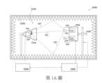
第1A圖~第1C圖是圖示用於評估DUT的測試系統的框圖。1A-1C are block diagrams illustrating a test system for evaluating a DUT.
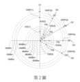
第2圖是說明與在不同方向上的DUT相關聯的功率電平的示意圖。FIG. 2 is a schematic diagram illustrating power levels associated with a DUT in different directions.
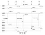
第3A圖是從第2圖的另一方面說明與DUT相關聯的功率電平的示意圖。FIG. 3A is a schematic diagram illustrating the power levels associated with the DUT from another aspect of FIG. 2 .
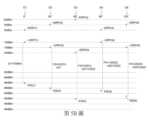
第3B圖~第3D圖是圖示根據第3A圖的測試方案的其他示例的與DUT相關聯的功率電平的示意圖。3B-3D are schematic diagrams illustrating power levels associated with a DUT according to other examples of the test scheme of FIG. 3A.
第4圖是說明根據關於第2圖的各種測試方案的在不同方向與DUT相關聯的功率電平的示意圖。FIG. 4 is a schematic diagram illustrating power levels associated with a DUT in different directions according to various test scenarios with respect to FIG. 2 .
第5A圖是從第4圖的另一方面說明與DUT相關聯的功率電平的示意圖。FIG. 5A is a schematic diagram illustrating the power levels associated with the DUT from another aspect of FIG. 4 .
第5B圖~第5D圖是圖示根據第5A圖的測試方案的其他示例的與DUT相關聯的功率電平的示意圖。FIGS. 5B-5D are schematic diagrams illustrating power levels associated with a DUT according to other examples of the test scheme of FIG. 5A.
第6A圖是圖示根據第3A圖~第3D圖的測試方案的用於評估DUT的測試方法的流程圖。FIG. 6A is a flowchart illustrating a test method for evaluating a DUT according to the test schemes of FIGS. 3A to 3D .
第6B圖是圖示根據第5A圖~第5D圖的測試方案的用於評估DUT的測試方法的流程圖。FIG. 6B is a flowchart illustrating a test method for evaluating a DUT according to the test scheme of FIGS. 5A-5D .
在以下詳細描述中,為了解釋的目的,闡述了許多具體細節以提供對所公開實施例的透徹理解。然而,顯而易見的是,可以在沒有這些具體細節的情況下實踐一個或複數個實施例。在其他情況下,習知的結構和設備被示意性地示出以簡化繪圖。In the following detailed description, for purposes of explanation, numerous specific details are set forth in order to provide a thorough understanding of the disclosed embodiments. It may be evident, however, that one or more embodiments may be practiced without these specific details. In other instances, well-known structures and devices are shown schematically to simplify drawing.
第1A圖~第1C圖是圖示用於評估DUT 1000的測試系統2000的框圖。DUT 1000可以指可以執行無線通訊的無線電設備。例如,DUT 1000可以指智慧型電話、智慧手錶或一組無線耳機中的一個等。DUT 1000可以透過Wi-Fi、Wi-Max、藍牙、4G LTE和5G NR(甚至未來的6G)無線協議等執行去往/來自遠端對等設備或遠端基地台的上行鏈路/下行鏈路通訊。1A-1C are block diagrams illustrating a
具體地,參考第1A圖,為了以無線方式執行雙工通訊(即,雙向通訊),DUT 1000可以包括TX路徑(即,發送路徑)100的電路和RX路徑(即,接收路徑)200。TX路徑100可以包括TX模組110和TX天線120,其中,TX模組110可以生成和處理(例如,調變、通道編碼等)基頻訊號,並且基頻訊號可以轉換為RF訊號。RF訊號可以被TX天線120輻射為TX訊號150,並且TX訊號150可以具有功率電平。另一方面,參考第1B圖,DUT 1000的RX路徑200可以包括RX模組210和RX天線220,其中RX路徑200可以用於接收測試訊號350。測試訊號350可以具有測試功率,並且可以透過RX天線220接收測試訊號350,然後透過RX模組210被處理(例如,解調、解碼、定時恢復等)。在第1A圖和第1B圖的示例中,DUT 1000的TX路徑100配備有TX天線120,並且RX路徑200配備有RX天線220,分別地。在如第1C圖所示的另一示例中,TX路徑100和RX路徑200可以共同使用(即,共用)單個天線400。即,TX路徑100可以發送TX訊號150並且RX路徑200可以透過同一天線400接收測試訊號350。Specifically, referring to FIG. 1A, in order to wirelessly perform duplex communication (i.e., two-way communication),
為了評估DUT 1000的TX路徑100和RX路徑200的輻射性能,可以在測試系統2000中提供消聲室(anechoic chamber)2100、處理模組2400和測量設備3000。如第1A圖和第1B圖所示,測量設備3000可以耦接並控制「喇叭天線(horn)」3100,同樣地,與測量裝置3000相關聯的TX天線320和RX天線310可以設置在喇叭天線3100內。喇叭天線3100與TX天線320和RX天線310以及DUT 1000一起設置在消聲室2100內。In order to evaluate the radiation performance of the
DUT 1000可以安裝在支撐底座2300上。支撐底座2300可以由處理模組2400控制,以便將DUT 1000佈置在一些選定的方向上,以評估DUT 1000在這些方向上的輻射性能。在一個示例中,DUT 1000可以佈置在方向O1、O2、O3、O4和O5等,它們分別是指0度、30度、60度、90度和120度。在其他示例中,這些用於佈置DUT 1000的方向O1、O2、O3、O4和O5可以以更接近的方式,例如分別為0度、5度、10度、15度和20度。此外,處理模組2400可以控制測量設備3000來調整測試訊號350的功率。此外,處理模組2400可以控制DUT 1000以設置TX訊號150。
在第1A圖和第1B圖的示例中,測量設備3000配備有TX天線320和RX天線310。在第1C圖所示的另一個示例中,測量設備3000可以使用單個天線330以操作,即測量裝置3000可以透過同一天線330發送測試訊號350和接收TX訊號150。In the examples of FIGS. 1A and 1B , the
第2圖是說明與在不同方向O1~O5上的DUT 1000相關聯的功率電平的示意圖。第3A圖是從第2圖的另一方面說明與DUT相關聯的功率電平的示意圖。參考第2圖和第3A圖,DUT 1000的第一方向O1(例如,0度)可以被選擇為「參考方向」,並且DUT 1000的TX-路徑100和RX-路徑200在第一方向O1處的輻射性能可以首先被評估為「參考」。在第一方向O1,由TX路徑100發送的TX訊號150可以透過視線(line-of-sight)路徑傳送或被消聲室2100的周圍壁2200反射到測量設備3000。與測量設備3000相關聯的一個或複數個天線(第1A圖和1B的示例中的TX天線320和RX天線310或第1C圖中的公共天線)可以針對複數個水平極化和垂直極化進行調整。對於測量設備3000的一個或複數個天線的所有極化,可以測量接收到的TX訊號150的功率電平以計算和確定EIRP。EIRP可以指用於評估DUT 1000的TX路徑100的輻射性能的性能指示或性能索引。在第一方向O1處確定的與TX路徑100相關聯的EIRP可以稱為「第一EIRP」或「EIRP(1)」。例如,在第一方向O1(例如,0度),EIRP(1)被確定為16dBm。處理模組2400可以控制測量設備3000針對所有水平和垂直極化調整其一個或複數個天線,以便計算和確定EIRP(1)。FIG. 2 is a schematic diagram illustrating power levels associated with
此後,可以評估DUT 1000的RX路徑200在第一方向O1處的輻射性能。EIS可以用作RX路徑200的性能指示或性能索引。為了測量與RX路徑200相關聯的EIS,測量設備3000可以以測試功率發送測試訊號350,並且測試訊號350可以是與資料位元(data-bits)相關聯的調變訊號。測試訊號350可由DUT 1000的RX路徑200接收和解調以檢索其資料位元。可以評估解調時資料位元的誤碼率(Bit error rate,BER),較小的BER表示較少的誤碼位,該較少的誤碼位元指示RX路徑200在給定測試訊號350的這種測試功率的情況下表現良好。因此,BER的值可以用作DUT 1000的RX路徑200的性能指示或性能索引,並且可以對DUT 1000進行調節測試(以BER為標準)。如果BER小於門檻,則表明DUT 1000的RX路徑200執行很好,DUT 1000可以透過監管測試。Thereafter, the radiation performance of the
可以調整測試訊號350的測試功率,並且可以在給定不同級別的測試功率的情況下對DUT 1000執行調節測試。如果測試功率太低(即測試訊號350太弱),則DUT 1000的RX路徑200不能很好地處理測試訊號350的資料位元,DUT 1000也不能通過調節測試。DUT 1000可以通過調節測試的測試訊號350的測試功率的「最小電平」被認為是EIS。在圖2和第3A圖所示的例子中,第一方向O1處的EIS(1)被確定為-86dBm(即,-86dBm是DUT 1000可以通過調節測試的測試訊號350的測試功率的「最小電平」)。此外,處理模組2400可以說明計算BER、將BER與門檻進行比較並識別測試功率的最小電平以確定EIS。The test power of
在另一個示例中,與測試訊號350的解調資料位元相關聯的另一個性能指示或性能索引「吞吐量中斷率」也可以用作DUT 1000的調節測試標準。當「吞吐量中斷率」小於或等於門檻,這可指示DUT 1000的RX路徑200表現良好,因此DUT 1000可以通過調節測試。In another example, another performance indicator or performance index “throughput outage rate” associated with the demodulated data bits of the
此後,處理模組2400可以控制支撐基座2300以將DUT 1000佈置在第二方向O2(例如,30度)以測量與DUT 1000的TX路徑100相關聯的EIRP。在第二方向O2的EIRP可以被稱為「第二EIRP」或「EIRP(2)」。EIRP(2)可以透過與確定第一方向O1處的EIRP(1)相同的方案來確定,並且在該示例中EIRP(2)可以被確定為18dBm。Thereafter, the
然後,可以確定與處於第二方向O2的DUT 1000的RX路徑200相關聯的EIS(稱為「第二EIS」或「EIS(2)」)。評估EIS(2)的測試方案可能與評估EIS(1)的測試方案不同。為了評估第二方向O2上的EIS(2),來自測量裝置3000的測試訊號350可能不需要「掃描」測試功率的寬功率範圍,相反,測試訊號350的測試功率可以直接從初始功率電平PI2開始。可以首先提供具有等於初始功率電平PI2的測試功率的測試訊號350以對DUT 1000進行調節測試。在調節測試中,檢查BER或「吞吐量中斷率」是否小於門檻。在一種情況下,如果DUT 1000在初始功率電平PI2下不能通過調節測試,則表明DUT 1000的RX路徑200在初始功率電平PI2下不能很好地執行。然後,測試訊號350的測試功率可以從初始功率電平PI2增加,並且再次對DUT 1000進行調節測試。如果增加了這樣的測試功率,DUT 1000仍然不能通過調節測試,可以進一步增加測試功率並且重新進行調節測試。可以重複上述測試方案,直到DUT 1000可以通過調節測試,並且第二方向O2上的EIS(2)被確定為DUT 1000可以通過調節測試的測試功率的「最小電平」。在第3A圖的例子中,在一種情況下,DUT 1000在-88dBm的初始功率電平PI2無法通過調節測試,則測試功率增加。測試功率不斷增加,增加到-86dBm時DUT 1000可以通過調節測試。也就是說,-86dBm是DUT 1000可以通過調節測試的測試功率的「最小電平」。因此,第二方向O2上的EIS(2)被確定為-86dBm。Then, the EIS associated with the
在另一種情況下,如果在初始功率電平PI2下DUT 1000可以通過調節測試,則測試訊號350的測試功率可以從初始功率電平PI2降低並且再次對DUT 1000執行調節測試。如果DUT 1000仍能通過調節測試,則測試功率將進一步降低。重複上述測試方案,直到DUT 1000無法通過調節測試。在第3A圖的例子中,在另一種情況下,如果DUT 1000可以在-88dBm的初始功率電平PI2下通過調節測試,則降低測試功率。當測試功率降低到-92dBm時,DUT 1000仍然可以通過調節測試,但是,如果測試功率降低到-92.1dBm,則發現DUT 1000無法透過調節。也就是說,-92dBm是DUT 1000可以通過調節測試的「最小電平」,EIS(2)被確定為-92dBm。In another case, if the
在上述測試方案中,測試訊號350的測試功率可能不需要「掃描」寬功率範圍來定位EIS(2)。相反,測試功率從初始功率電平PI2開始,並且僅「掃描」初始功率電平PI2附近的功率範圍。如果DUT 1000在初始功率電平PI2不能通過調節測試,則測試功率從初始功率電平PI2增加(即,在初始功率電平PI2之上的功率範圍內調整測試功率)。另一方面,如果DUT 1000可以在初始功率電平PI2下通過調節測試,則測試功率從初始功率電平PI2降低(即在初始功率電平PI2之下的功率範圍內調整測試功率)。也就是說,測試功率只需要在接近(即高於或低於)初始功率電平PI2的較窄功率範圍內進行調整,從而可以減少確定EIS(2)的測試時間。In the above test scheme, the test power of the
更具體地,在上述測試方案中,初始功率電平PI2可以被設置為「負EIRP(2)減去偏移值F2」。偏移值F2可以等於由校正函數C2校正的差值D1,其中校正函數C2用於動態調整或校正偏移值F2,使得偏移值F2可以更加精確。在第3A圖的例子中,校正函數C2可以將偏移值F2校正為等於差值D1。確定初始功率電平PI2的方案如等式(1-1)~(1-3)所示:D1=(-EIRP(1))-EIS(1)=(-16dBm)-(-86dBm)=70dBm 等式(1-1)More specifically, in the above test scheme, the initial power level PI2 can be set as "negative EIRP(2) minus the offset value F2". The offset value F2 can be equal to the difference D1 corrected by the correction function C2, wherein the correction function C2 is used to dynamically adjust or correct the offset value F2, so that the offset value F2 can be more accurate. In the example of FIG. 3A, correction function C2 may correct offset value F2 to be equal to difference value D1. The scheme for determining the initial power level PI2 is shown in equations (1-1)~(1-3): D1=(-EIRP(1))-EIS(1)=(-16dBm)-(-86dBm)= 70dBm Equation (1-1)
F2=C2(D1)=D1=70dBm 等式(1-2)F2=C2(D1)=D1=70dBm Equation (1-2)
PI2=(-EIRP(2))-F2=(-18dBm)-(70dBm)=-88dBm 等式(1-3)PI2=(-EIRP(2))-F2=(-18dBm)-(70dBm)=-88dBm Equation (1-3)
隨後,DUT 1000可以被佈置在下一個方向,即第三方向O3(例如,60度)。在第三方向O3處,EIRP(3)(或稱為「第三EIRP」)可以使用與評估EIRP(2)和EIRP(1)相同的方案進行測量,並且測得的EIRP(3)為20dBm。然後,測試訊號350的測試功率的初始功率電平PI3可以被設置為「負EIRP(3)減去偏移值F3」。在第2圖和第3A圖的例子中,如果校正函數C3可以將偏移值F3校正為等於差值D1,確定初始功率電平PI3的方案如等式(1-4)和(1-5)所示:F3=C3(D1)=D1=70dBm 等式(1-4)Subsequently,
PI3=(-EIRP(3))-F3=(-20dBm)-(70dBm)=-90dBm 等式(1-5)PI3=(-EIRP(3))-F3=(-20dBm)-(70dBm)=-90dBm Equation (1-5)
然後,可以採用具有從-90dBm的初始功率電平PI3開始的測試功率的測試訊號350來評估第三方向O3上的「第三EIS」或「EIS(3)」,其方案與確定EIS(2)的方案相同。在圖2和第3A圖的例子中,EIS(3)被確定為-92dBm。The "third EIS" or "EIS(3)" in the third direction O3 can then be evaluated using the
同樣,用於評估EIRP(2)、EIS(2)、EIRP(3)和EIS(3)的相同方案可用於其他方向O4和O5等。在第2圖和第3A圖的例子中,初始功率電平PI4可以被設置為「負EIRP(4)減去偏移值F4」,並且初始功率電平PI5可以被設置為「負EIRP(5)減去偏移值F5」。此外,校正函數C4和C5還可以將偏移值F4和F5校正為等於差值D1,如等式(1-6)~(1-9)所示:F4=C4(D1)=D1=70dBm 等式(1-6)Likewise, the same protocol used to evaluate EIRP(2), EIS(2), EIRP(3) and EIS(3) can be used for other directions O4 and O5 etc. In the example of Figures 2 and 3A, the initial power level PI4 can be set to "negative EIRP(4) minus the offset value F4", and the initial power level PI5 can be set to "negative EIRP(5 ) minus the offset value F5". In addition, the correction functions C4 and C5 can also correct the offset values F4 and F5 to be equal to the difference D1, as shown in equations (1-6)~(1-9): F4=C4(D1)=D1=70dBm Equation (1-6)
F5=C5(D1)=D1=70dBm 等式(1-7)F5=C5(D1)=D1=70dBm Equation (1-7)
PI4=(-EIRP(4))-F4=(-16dBm)-(70dBm)=-86dBm 等式(1-8)PI4=(-EIRP(4))-F4=(-16dBm)-(70dBm)=-86dBm Equation (1-8)
PI5=(-EIRP(5))-F5=(-18dBm)-(70dBm)=-88dBm 等式(1-9)PI5=(-EIRP(5))-F5=(-18dBm)-(70dBm)=-88dBm Equation (1-9)
在方向O4上,測試訊號350的測試功率可以從-86dBm的初始功率電平PI4開始,然後將EIS(4)定位為-90dBm。同樣,在方向O5上,測試訊號350的測試功率可以從-88dBm的初始功率電平PI5開始,然後將EIS(5)定位為-94dBm。In direction O4, the test power of the
在第2圖和第3A圖的例子中,在感興趣的方向,例如第二方向O2,根據測試訊號350確定EIS(2),測試功率從初始功率電平PI2開始。此外,初始功率電平PI2設定為「負EIRP(2)減去偏移值F2」,其中偏移值F2根據EIRP(1)和EIS(1)設定。即,根據EIRP(2)、EIRP(1)和EIS(1)之間的相關性確定EIS(2)。換句話說,感興趣的方向On處的EIS(n)是根據方向On處的EIRP(n)與先前相鄰方向On-1處的EIRP(n-1)和EIS(n-1)之間的相關性確定的。在第2圖和第3A圖的例子中,校正函數C2~C5可以將偏移值F2~F5校正為都等於相同的值,即負ERIP(1)與EIS(1)之間的差值D1。在其他示例中,偏移值F2~F5可以透過校正函數C2~C5動態地校正,使得偏移值F2~F5彼此不同,如將在以下段落中參照第3B圖和第3C圖討論的。In the example of Figures 2 and 3A, in the direction of interest, e.g. the second directionO2, determine EIS(2) according to the
第3B圖~第3D圖是說明根據第3A圖的測試方案的其他實例的與DUT相關聯的功率電平的示意圖。首先,參考第3B圖,用於設置初始功率電平PIn的偏移值Fn可以透過校正函數Cn作為前兩個方向的差值Dn-2和Dn-1的平均值來校正。校正函數Cn可以將偏移值Fn校正為「(Dn-2+Dn-1)/2」,即校正函數Cn可以將偏移值Fn從「Dn-2」校正為「(Dn-2+Dn-1)/2」。當EIS(2)確定時,可以得到負EIRP(2)與EIS(2)的差值D2,可以利用差值D2對偏移值F3進行校正。例如,偏移值F3可以被校正為差值D1和D2的平均值(即,F3=(D1+D2)/2),並且初始功率電平PI3被設置為「負EIRP(3)減去偏移值F3」。然後,根據從初始功率電平PI3開始的測試功率確定EIS(3)。然後,獲得負EIRP(3)和EIS(3)之間的差值D3。3B-3D are schematic diagrams illustrating power levels associated with a DUT according to other examples of the test scheme of FIG. 3A. First, referring to FIG. 3B, the offset value Fn for setting the initial power level PIn can be corrected by the correction function Cn as the average value of the differences Dn-2 and Dn-1 in the first two directions. The correction function Cn can correct the offset value Fn to "(Dn-2+Dn-1)/2", that is, the correction function Cn can correct the offset value Fn from "Dn-2" to "(Dn-2+Dn -1)/2". When EIS(2) is determined, the difference D2 between negative EIRP(2) and EIS(2) can be obtained, and the offset value F3 can be corrected by using the difference D2. For example, offset value F3 may be corrected to be the average of differences D1 and D2 (i.e., F3=(D1+D2)/2), and initial power level PI3 set to "negative EIRP(3) minus offset Shift value F3". Then, EIS(3) is determined from the test power starting from the initial power level PI3. Then, the difference D3 between negative EIRP(3) and EIS(3) is obtained.
同樣,在第四和第五方向O4和O5上,偏移值F4被設置為差值D2和D3的平均值,並且偏移值F5被設置為差值D3和D4的平均值。第3B圖中採用的上述測試方案表示為等式(2-1)~(2-8):F2=C2(D1)=D1=70dBm 等式(2-1)Also, in the fourth and fifth directions O4 and O5, the offset value F4 is set as the average value of the differences D2 and D3, and the offset value F5 is set as the average value of the differences D3 and D4. The above test scheme adopted in Figure 3B is expressed as equations (2-1)~(2-8): F2=C2(D1)=D1=70dBm Equation (2-1)
PI2=(-EIRP(2))-F2=(-18dBm)-(70dBm)=-88dBm 等式(2-2)PI2=(-EIRP(2))-F2=(-18dBm)-(70dBm)=-88dBm Equation (2-2)
F3=C3(D1)=(D1+D2)/2=(70dBm+74dBm)/2=72dBm 等式(2-3)F3=C3(D1)=(D1+D2)/2=(70dBm+74dBm)/2=72dBm Equation (2-3)
PI3=(-EIRP(3))-F3=(-20dBm)-(72dBm)=-92dBm 等式(2-4)PI3=(-EIRP(3))-F3=(-20dBm)-(72dBm)=-92dBm Equation (2-4)
F4=C4(D2)=(D2+D3)/2=(74dBm+72dBm)/2=73dBm 等式(2-5)F4=C4(D2)=(D2+D3)/2=(74dBm+72dBm)/2=73dBm Equation (2-5)
PI4=(-EIRP(4))-F4=(-16dBm)-(73dBm)=-89dBm 等式(2-6)PI4=(-EIRP(4))-F4=(-16dBm)-(73dBm)=-89dBm Equation (2-6)
F5=C5(D3)=(D3+D4)/2=(72dBm+74dBm)/2=73dBm 等式(2-7)F5=C5(D3)=(D3+D4)/2=(72dBm+74dBm)/2=73dBm Equation (2-7)
PI5=(-EIRP(5))-F5=(-18dBm)-(73dBm)=-91dBm 等式(2-8)PI5=(-EIRP(5))-F5=(-18dBm)-(73dBm)=-91dBm Equation (2-8)
在第3B圖的例子中,根據在方向On處的EIRP(n)與在前兩個方向On-2和On-1處的EIRP(n-2)、EIS(n-2)、EIRP(n-1)和EIS(n)之間的相關性確定感興趣方向On處的EIS(n)。In the example in Figure 3B, according to the EIRP(n) at the direction On and the EIRP(n-2), EIS(n-2), EIRP(n) at the first two directions On-2 and On-1 The correlation between -1) and EIS(n) determines the EIS(n) at the direction of interest On.
接下來,在第3C圖的例子中,偏移值Fn可以被校正為所有先前方向的差值D1、D2、……、Dn-2和Dn-1的平均值。校正函數Cn可以將偏移值Fn校正為等於「(D1+D2+...+Dn-2+Dn-1)/(n-1)」,即校正函數Cn可以將偏移值Fn從「D1」校正為「(D1+D2+...+Dn-2+Dn-1)/(n-1)」。例如,在第四方向O4,偏移值F4被設置為差值D1、D2和D3的平均值。同樣,在第五方向O5,偏移值F5被設置為差值D1、D2、D3和D4的平均值。第3C圖的例子的方案可表示為等式(3-1)~(3-8):F2=C2(D1)=D1=70dBm 等式(3-1)Next, in the example of FIG. 3C, the offset value Fn may be corrected as the average value of the differences D1, D2, . . . , Dn-2 and Dn-1 of all previous directions. The correction function Cn can correct the offset value Fn to be equal to "(D1+D2+...+Dn-2+Dn-1)/(n-1)", that is, the correction function Cn can change the offset value Fn from "D1 " is corrected to "(D1+D2+...+Dn-2+Dn-1)/(n-1)". For example, in the fourth direction O4, the offset value F4 is set as the average value of the difference values D1, D2 and D3. Likewise, in the fifth direction O5, the offset value F5 is set as the average value of the differences D1, D2, D3 and D4. The scheme of the example in Figure 3C can be expressed as equations (3-1)~(3-8): F2=C2(D1)=D1=70dBm Equation (3-1)
PI2=(-EIRP(2))-F2=(-18dBm)-(70dBm)=-88dBm 等式(3-2)PI2=(-EIRP(2))-F2=(-18dBm)-(70dBm)=-88dBm Equation (3-2)
F3=C3(D1)=(D1+D2)/2=(70dBm+74dBm)/2=72dBm 等式(3-3)F3=C3(D1)=(D1+D2)/2=(70dBm+74dBm)/2=72dBm Equation (3-3)
PI3=(-EIRP(3))-F3=(-20dBm)-(72dBm)=-92dBm 等式(3-4)PI3=(-EIRP(3))-F3=(-20dBm)-(72dBm)=-92dBm Equation (3-4)
F4=C4(D1)=(D1+D2+D3)/3=(70dBm+74dBm+72dBm)/3=72dBm 等式(3-5)F4=C4(D1)=(D1+D2+D3)/3=(70dBm+74dBm+72dBm)/3=72dBm Equation (3-5)
PI4=(-EIRP(4))-F4=(-16dBm)-(72dBm)=-88dBm 等式(3-6)PI4=(-EIRP(4))-F4=(-16dBm)-(72dBm)=-88dBm Equation (3-6)
F5=C5(D1)=(D1+D2+D3+D4)/4=(70dBm+74dBm+72dBm+74dBm)/4=72.5dBm 等式(3-7)F5=C5(D1)=(D1+D2+D3+D4)/4=(70dBm+74dBm+72dBm+74dBm)/4=72.5dBm Equation (3-7)
PI5=(-EIRP(5))-F5=(-18dBm)-(72.5dBm)=-90.5dBm 等式(3-8)PI5=(-EIRP(5))-F5=(-18dBm)-(72.5dBm)=-90.5dBm Equation (3-8)
在第3C圖的例子中,在感興趣的方向On處的EIS(n)是根據方向On處的EIRP(n)和之前所有方向O1、O2、...、On-2和On-1處的差值D1、D2、……、Dn-2和Dn-1確定的。換句話說,EIS(n)是根據方向On處的EIRP(n)與方向所有之前方向O1~On-1處的EIRP(1)~EIRP(n-1)和EIS(1)~EIS(n-1)之間的相關性確定的。In the example in Figure 3C, the EIS(n) at the direction of interest On is based on the EIRP(n) at the direction On and all previous directions O1, O2, ..., On-2 and On-1 The differences D1, D2, ..., Dn-2 and Dn-1 are determined. In other words, EIS(n) is based on EIRP(n) at direction On and EIRP(1)~EIRP(n-1) and EIS(1)~EIS(n) at all previous directions O1~On-1 in direction -1) The correlation between is determined.
接下來,在第3D圖的例子中,可以選擇方向O1、O3和O5,並且可以根據測試訊號350的測試功率「實際測量」EIS(1)、EIS(3)和EIS(5)。然後,可以得到負ERIP(1)和EIS(1)之間的差值D1、負ERIP(3)和EIS(3)之間的差值D3,以及負ERIP(5)和EIS(5)之間的差值D5。然後,偏移值F2可以被確定為差值D1和D3的插值(interpolation)(例如,平均值),並且初始功率電平PI2被設置為「負EIRP(2)減去偏移值F2」。然後,測試訊號350的測試功率從初始功率電平PI2開始,評估DUT 1000的RX路徑200並進行調節測試,並且EIS(2)被確定為DUT 1000通過調節測試的最小測試功率電平。同樣地,偏移值F4可以被確定為差值D3和D5的插值(例如,平均值),並且初始功率電平PI4被設置為「負EIRP(4)減去偏移值F4」。然後,測試訊號350的測試功率從初始功率電平PI4開始到確定的EIS(4)。Next, in the example in the 3D diagram, directions O1 , O3 and O5 can be selected, and EIS(1), EIS(3) and EIS(5) can be “actually measured” according to the test power of the
由上可知,在第2圖和第3A圖~第3D圖示例中,以從初始功率電平PIn開始的測試功率根據測試訊號350「實際測量」在方向On處的EIS(n)。在其他例子中,為了進一步減少評估EIS(n)的測試時間,測試系統2000可不需要「實際測量」EIS(n),而是透過「估計」來確定EIS(n),如將在以下段落中參考第4圖和第5A圖~第5D圖討論的。It can be known from the above that, in the examples in Fig. 2 and Fig. 3A ~ Fig. 3D, the EIS(n) in the direction On is "actually measured" according to the
第4圖是圖示根據關於第2圖的各種測試方案的在不同方向O1~O5與DUT 1000相關聯的功率電平的示意圖。第5A圖是從第4圖的另一方面說明與DUT 1000相關聯的功率電平的示意圖。在第4圖和第5A圖的例子中,僅針對第一方向O1(即參考方向)EIS(1)是根據測試訊號350「實際測量」的。另一方面,對於其他方向O2、O3、O4和O5等,EIS(2)、EIS(3)、EIS(4)和EIS(5)不是「實際測量」的,而是直接由「估計」決定。例如,EIS(2)可以估計為「負EIRP(2)減去偏移值F2」,並且EIS(3)可以估計為「負EIRP(3)減去偏移值F3」等。在第4圖和第5A圖的例子中,校正函數C2、C3、C4和C5可以將偏移值F2、F3、F4和F5校正為等於差值D1。這樣,EIS(2)~EIS(5)可以確定為等式(4-1a)~(4-8):F2=C2(D1)=D1=70dBm 等式(4-1a)Figure 4 is a diagram illustrating O1 in different directions according to various test scenarios related to Figure 2~05 Schematic diagram of power levels associated with
F3=C3(D1)=D1=70dBm 等式(4-1b)F3=C3(D1)=D1=70dBm Equation (4-1b)
F4=C4(D1)=D1=70dBm 等式(4-1c)F4=C4(D1)=D1=70dBm Equation (4-1c)
F5=C5(D1)=D1=70dBm 等式(4-1d)F5=C5(D1)=D1=70dBm Equation (4-1d)
EIS(2)=(-EIRP(2))-F2=(-18dBm)-(70dBm)=-88dBm 等式(4-2)EIS(2)=(-EIRP(2))-F2=(-18dBm)-(70dBm)=-88dBm Equation (4-2)
EIS(3)=(-EIRP(3))-F3=(-20dBm)-(70dBm)=-90dBm 等式(4-3)EIS(3)=(-EIRP(3))-F3=(-20dBm)-(70dBm)=-90dBm Equation (4-3)
EIS(4)=(-EIRP(4))-F4=(-16dBm)-(70dBm)=-86dBm 等式(4-4)EIS(4)=(-EIRP(4))-F4=(-16dBm)-(70dBm)=-86dBm Equation (4-4)
EIS(5)=(-EIRP(5))-F5=(-18dBm)-(70dBm)=-88dBm 等式(4-5)EIS(5)=(-EIRP(5))-F5=(-18dBm)-(70dBm)=-88dBm Equation (4-5)
第5B圖~第5D圖是圖示根據第5A圖的測試方案的其他示例的與DUT相關聯的功率電平的示意圖。在第5B圖的例子中,EIS(2)~EIS(5)仍可分別估計為負EIRP(2)~負EIRP(5)減去偏移值F2~F5。此外,偏移值Fn可以透過校正函數C2~C5校正為前兩個方向On-2和On-1處的差值Dn-2和Dn-1的平均值來。或者,在第5C圖例子中,偏移值Fn可以透過校正函數C2~C5校正為在所有先前方向O1~On-1處的差值D1~Dn-1的平均值。FIGS. 5B-5D are schematic diagrams illustrating power levels associated with a DUT according to other examples of the test scheme of FIG. 5A. In the example in FIG. 5B , EIS(2)~EIS(5) can still be estimated as negative EIRP(2)~negative EIRP(5) minus the offset values F2~F5, respectively. In addition, the offset value Fn can be corrected as the average value of the differences Dn-2 and Dn-1 at the first two directions On-2 and On-1 through the correction functions C2-C5. Alternatively, in the example in FIG. 5C , the offset value Fn can be corrected as the average value of the differences D1 ˜ Dn−1 in all previous directions O1 ˜ On−1 through the correction functions C2 ˜ C5 .
另一方面,在第5D圖例子中,可以根據測試訊號350的測試功率選擇方向O1、O3和O5並且可以「實際測量」EIS(1)、EIS(3)和EIS(5)。然後,可以得到負ERIP(1)和EIS(1)之間的差值D1、負ERIP(3)和EIS(3)之間的差值D3,以及負ERIP(5)和EIS(5)之間的差值D5。然後,偏移值F2可以被確定為差值D1和D3的插值(例如,平均值),並且EIS(2)被估計為「負EIRP(2)減去偏移值F2」。同樣地,偏移值F4可以被確定為差值D3和D5的插值(例如,平均值),並且EIS(4)被估計為「負EIRP(4)減去偏移值F4」。On the other hand, in the example shown in Figure 5D, the test function according to the
在第4圖和第5A圖~第5D圖的各種示例中,EIS(2)~EIS(5)分別估計為負EIRP(2)~負EIRP(5)減去偏移值F2~F5,其中偏移值F2~F5可與那些在第2圖和第3A圖~第3D圖例子中的相同。換句話說,第4圖和第5A圖~第5D圖的估計的EIS(2)~EIS(5)可以與第2圖和第3A圖~第3D圖的初始功率電平PI2~PI5基本相同。In the various examples in Figures 4 and 5A~5D, EIS(2)~EIS(5) are estimated as negative EIRP(2)~negative EIRP(5) minus offset values F2~F5, respectively, where The offset values F2-F5 may be the same as those in the examples in FIG. 2 and FIGS. 3A-3D. In other words, the estimated EIS(2)~EIS(5) of Figure 4 and Figure 5A~5D can be substantially the same as the initial power levels PI2~PI5 of Figure 2 and Figure 3A~3D .
第6A圖是圖示根據第3A圖和第3D圖的測試方案的用於評估DUT的測試方法的流程圖。參考第6A圖,首先,在步驟S110,使用處理模組2400控制支撐座2300將DUT 1000佈置在第一方向O1,並使用處理模組2400和測量設備3000在第一方向O1測量DUT 1000的EIRP(1)和EIS(1)。然後,在步驟S120,使用處理模組2400計算負EIRP(1)和EIS(1)之間的差值D1。接著,在步驟S130,控制支撐座2300將DUT 1000佈置在第二方向O2,並使用處理模組2400及測量設備3000在第二方向O2測量DUT 1000的EIRP(2)。FIG. 6A is a flowchart illustrating a test method for evaluating a DUT according to the test scenarios of FIGS. 3A and 3D . Referring to FIG. 6A, first, in step S110, use the
然後,在步驟S140,設置偏移值F2,並使用校正函數C2來校正偏移值F2。例如,偏移值F2可以等於差值D1,或者偏移值F2可以被校正為差值D1和其他一個或複數個方向上的其他差值的平均值。然後,在步驟S150,將初始功率電平PI2設置為「負EIRP(2)減去偏移值F2」,並以從初始功率電平PI2開始的測試功率發送測試訊號350。然後,在步驟S160,對與測試訊號350相關的DUT 1000執行調節測試,其中計算DUT 1000的性能索引(例如,與從測試訊號350解調的資料位元相關聯的BER或「吞吐量中斷率(throughput outage)」)作為調節測試的標準。Then, in step S140, the offset value F2 is set, and the offset value F2 is corrected using the correction function C2. For example, the offset value F2 may be equal to the difference value D1, or the offset value F2 may be corrected as the average value of the difference value D1 and other differences in one or more directions. Then, in step S150 , the initial power level PI2 is set as “negative EIRP(2) minus the offset value F2 ”, and the
然後,在步驟S170,從初始功率電平PI2增加或減少測試功率,並以這種增加或減少的測試功率重複調節測試。此外,確定DUT 1000可以通過調節測試的測試功率的「最小電平」。例如,在一種情況下,如果DUT 1000在初始功率電平PI2無法通過調節測試,則反復增加測試功率並進行調節測試,直到確定出DUT 1000通過調節測試的測試功率的「最小電平」。另一方面,在另一種情況下,如果DUT 1000可以在初始功率電平PI2下通過調節測試,則反復降低測試功率並進行調節測試,直到確定出DUT 1000通過調節測試的測試功率的「最小電平」。然後,在步驟S180,將DUT 1000通過調節測試的測試功率的「最小電平」視為EIS(2),並最終確定EIS(2)。Then, at step S170, the test power is increased or decreased from the initial power level PI2, and the conditioning test is repeated with this increased or decreased test power. Additionally, a "minimum level" of test power at which the
第6B圖是圖示根據第5A圖~第5D圖的測試方案的用於評估DUT的測試方法的流程圖。在第6B圖的例子中,步驟S210~S240可以與第6A圖的步驟S110~S140相同。此外,在步驟S250中,估計EIS(2)為「負EIRP(2)減去偏移值F2」。也就是說,在步驟S250中,EIS(2)不是「實際測量」的,而是直接透過估計確定EIS(2)。FIG. 6B is a flowchart illustrating a test method for evaluating a DUT according to the test scheme of FIGS. 5A-5D . In the example of FIG. 6B, steps S210-S240 may be the same as steps S110-S140 of FIG. 6A. In addition, in step S250, the estimated EIS(2) is "negative EIRP(2) minus the offset value F2". That is to say, in step S250, EIS(2) is not "actually measured", but EIS(2) is determined directly through estimation.
根據本發明的測試系統2000和測試方法中採用的測試方案的各種示例,可以選擇一個或複數個方向(例如0度處的第一方向O1)作為一個或複數個參考方向,並且可以首先測量一個或複數個參考方向上的EIRP和EIS。然後,可以根據該感興趣方向On處的EIRP(n)與一個或複數個參考方向處的EIRP和EIS之間的相關性來確定感興趣方向On處的EIS(n)。與採用低準確性RSSI的傳統測試方案相比,本發明採用EIRP(其比RSSI更準確)來測量或估計EIS,從而可以實現更高的準確度。此外,測試訊號350的測試功率可直接從初始功率電平PIn開始以快速定位EIS,從而可減少確定EIS的測試時間。According to various examples of the test scheme adopted in the
對所屬技術領域具有通常知識者顯而易見的是,可以對所公開的實施例進行各種修改和變化。說明書和示例旨在僅被視為示例性的,本發明的真實範圍由以下請求項及其等同物指示。Various modifications and changes to the disclosed embodiments will be apparent to those having ordinary skill in the art. It is intended that the specification and examples be considered exemplary only, with the true scope of the invention being indicated by the following claims and their equivalents.
S110,S120,S130,S140,S150,S160,S170,S180:步驟S110, S120, S130, S140, S150, S160, S170, S180: steps
Claims (20)
Translated fromChinesePriority Applications (1)
| Application Number | Priority Date | Filing Date | Title |
|---|---|---|---|
| TW110146826ATWI797887B (en) | 2021-12-14 | 2021-12-14 | Testing method and testing system for determining radiation performance of a device under test (dut) |
Applications Claiming Priority (1)
| Application Number | Priority Date | Filing Date | Title |
|---|---|---|---|
| TW110146826ATWI797887B (en) | 2021-12-14 | 2021-12-14 | Testing method and testing system for determining radiation performance of a device under test (dut) |
Publications (2)
| Publication Number | Publication Date |
|---|---|
| TWI797887Btrue TWI797887B (en) | 2023-04-01 |
| TW202323832A TW202323832A (en) | 2023-06-16 |
Family
ID=86945158
Family Applications (1)
| Application Number | Title | Priority Date | Filing Date |
|---|---|---|---|
| TW110146826ATWI797887B (en) | 2021-12-14 | 2021-12-14 | Testing method and testing system for determining radiation performance of a device under test (dut) |
Country Status (1)
| Country | Link |
|---|---|
| TW (1) | TWI797887B (en) |
Citations (5)
| Publication number | Priority date | Publication date | Assignee | Title |
|---|---|---|---|---|
| WO2006047677A1 (en)* | 2004-10-25 | 2006-05-04 | Qualcomm Incorporated | Systems, methods and apparatus for determining a radiated performance of a wireless device |
| TW200838180A (en)* | 2006-09-08 | 2008-09-16 | Qualcomm Inc | Radiated performance of a wireless device |
| WO2011134206A1 (en)* | 2010-04-26 | 2011-11-03 | 深圳市鼎立方无线技术有限公司 | Method and device for testing effective isotropic sensitivity |
| CN113162706A (en)* | 2020-01-22 | 2021-07-23 | 深圳市通用测试系统有限公司 | Radio frequency performance test method and system for wireless equipment |
| US20210364563A1 (en)* | 2020-05-20 | 2021-11-25 | Anritsu Corporation | Mobile terminal testing device and mobile terminal testing method |
- 2021
- 2021-12-14TWTW110146826Apatent/TWI797887B/enactive
Patent Citations (5)
| Publication number | Priority date | Publication date | Assignee | Title |
|---|---|---|---|---|
| WO2006047677A1 (en)* | 2004-10-25 | 2006-05-04 | Qualcomm Incorporated | Systems, methods and apparatus for determining a radiated performance of a wireless device |
| TW200838180A (en)* | 2006-09-08 | 2008-09-16 | Qualcomm Inc | Radiated performance of a wireless device |
| WO2011134206A1 (en)* | 2010-04-26 | 2011-11-03 | 深圳市鼎立方无线技术有限公司 | Method and device for testing effective isotropic sensitivity |
| CN113162706A (en)* | 2020-01-22 | 2021-07-23 | 深圳市通用测试系统有限公司 | Radio frequency performance test method and system for wireless equipment |
| US20210364563A1 (en)* | 2020-05-20 | 2021-11-25 | Anritsu Corporation | Mobile terminal testing device and mobile terminal testing method |
Also Published As
| Publication number | Publication date |
|---|---|
| TW202323832A (en) | 2023-06-16 |
Similar Documents
| Publication | Publication Date | Title |
|---|---|---|
| KR102179044B1 (en) | Apparatus and method for adjusting a receive beam gain in wireless communication system | |
| US20210051678A1 (en) | Wireless communication system, wireless communication method, base station, and terminal | |
| US9143967B2 (en) | Method and apparatus for determining distance in a Wi-Fi network | |
| US9294177B2 (en) | System and method for transmit and receive antenna patterns calibration for time division duplex (TDD) systems | |
| US20190271775A1 (en) | Motion detection using the magnitude of channel impulse response | |
| US20030068984A1 (en) | Pathloss aided closed loop power control | |
| US8843071B2 (en) | Method and apparatus for controlling interference in near field communication network including a plurality of connections for direct communication between terminals | |
| RU2011148605A (en) | METHOD FOR TRANSMISSION OF THE RISING LINK TO THE MULTIPLE ANTENNAS | |
| WO2011134206A1 (en) | Method and device for testing effective isotropic sensitivity | |
| CN110235413B (en) | Method for estimating receiver sensitivity of data packet signal transceiver | |
| CN112567642B (en) | Beam training performed by end device | |
| US20160301588A1 (en) | System and method for testing wireless data packet signal transceiver | |
| CN107872284B (en) | Self-excitation detection method and device of wireless repeater | |
| WO2012009867A1 (en) | Method and device for testing total isotropic sensitivity of mobile terminal | |
| WO2014190609A1 (en) | Method and system for testing mobile terminal wifi ota | |
| US11515952B1 (en) | Testing method and testing system for evaluating radio device | |
| TWI797887B (en) | Testing method and testing system for determining radiation performance of a device under test (dut) | |
| US11722200B2 (en) | Apparatuses and methods for RSRP measurements for a wireless device with variable output power per antenna arrangement | |
| WO2012009868A1 (en) | Method and device for testing total isotropic sensitivity of mobile terminal | |
| WO2022052571A1 (en) | Terminal communication control method and communication device, and storage medium | |
| US20150023193A1 (en) | Channel quality indication with filtered interference | |
| US20060009250A1 (en) | Apparatus and method for determining access power in a mobile communication system | |
| US20130033980A1 (en) | Communications system providing enhanced channel switching features based upon modulation fidelity and related methods | |
| KR101862285B1 (en) | Bluetooth Low Energy (BLE) Distance Estimation Method of Mobile Device Using Beacon Transmission Signal | |
| KR20130086870A (en) | Method for transmitting signal of multiple antennas base station and apparatus thereof |