TWI796013B - Power controller and control method for power converter - Google Patents
Power controller and control method for power converterDownload PDFInfo
- Publication number
- TWI796013B TWI796013BTW110144130ATW110144130ATWI796013BTW I796013 BTWI796013 BTW I796013BTW 110144130 ATW110144130 ATW 110144130ATW 110144130 ATW110144130 ATW 110144130ATW I796013 BTWI796013 BTW I796013B
- Authority
- TW
- Taiwan
- Prior art keywords
- signal
- time
- power
- current
- soft
- Prior art date
Links
- 238000000034methodMethods0.000titleclaimsdescription16
- 230000007423decreaseEffects0.000claimsabstractdescription12
- 238000001514detection methodMethods0.000claimsdescription34
- 230000003247decreasing effectEffects0.000claims1
- 230000001939inductive effectEffects0.000abstractdescription6
- 239000003990capacitorSubstances0.000description13
- 238000004804windingMethods0.000description7
- 238000006243chemical reactionMethods0.000description6
- 230000009977dual effectEffects0.000description2
- 230000006698inductionEffects0.000description1
- 238000012986modificationMethods0.000description1
- 230000004048modificationEffects0.000description1
Images


Classifications
- H—ELECTRICITY
- H02—GENERATION; CONVERSION OR DISTRIBUTION OF ELECTRIC POWER
- H02M—APPARATUS FOR CONVERSION BETWEEN AC AND AC, BETWEEN AC AND DC, OR BETWEEN DC AND DC, AND FOR USE WITH MAINS OR SIMILAR POWER SUPPLY SYSTEMS; CONVERSION OF DC OR AC INPUT POWER INTO SURGE OUTPUT POWER; CONTROL OR REGULATION THEREOF
- H02M3/00—Conversion of DC power input into DC power output
- H02M3/22—Conversion of DC power input into DC power output with intermediate conversion into AC
- H02M3/24—Conversion of DC power input into DC power output with intermediate conversion into AC by static converters
- H02M3/28—Conversion of DC power input into DC power output with intermediate conversion into AC by static converters using discharge tubes with control electrode or semiconductor devices with control electrode to produce the intermediate AC
- H02M3/325—Conversion of DC power input into DC power output with intermediate conversion into AC by static converters using discharge tubes with control electrode or semiconductor devices with control electrode to produce the intermediate AC using devices of a triode or a transistor type requiring continuous application of a control signal
- H02M3/335—Conversion of DC power input into DC power output with intermediate conversion into AC by static converters using discharge tubes with control electrode or semiconductor devices with control electrode to produce the intermediate AC using devices of a triode or a transistor type requiring continuous application of a control signal using semiconductor devices only
- H02M3/33507—Conversion of DC power input into DC power output with intermediate conversion into AC by static converters using discharge tubes with control electrode or semiconductor devices with control electrode to produce the intermediate AC using devices of a triode or a transistor type requiring continuous application of a control signal using semiconductor devices only with automatic control of the output voltage or current, e.g. flyback converters
- H—ELECTRICITY
- H02—GENERATION; CONVERSION OR DISTRIBUTION OF ELECTRIC POWER
- H02M—APPARATUS FOR CONVERSION BETWEEN AC AND AC, BETWEEN AC AND DC, OR BETWEEN DC AND DC, AND FOR USE WITH MAINS OR SIMILAR POWER SUPPLY SYSTEMS; CONVERSION OF DC OR AC INPUT POWER INTO SURGE OUTPUT POWER; CONTROL OR REGULATION THEREOF
- H02M3/00—Conversion of DC power input into DC power output
- H02M3/22—Conversion of DC power input into DC power output with intermediate conversion into AC
- H02M3/24—Conversion of DC power input into DC power output with intermediate conversion into AC by static converters
- H02M3/28—Conversion of DC power input into DC power output with intermediate conversion into AC by static converters using discharge tubes with control electrode or semiconductor devices with control electrode to produce the intermediate AC
- H02M3/325—Conversion of DC power input into DC power output with intermediate conversion into AC by static converters using discharge tubes with control electrode or semiconductor devices with control electrode to produce the intermediate AC using devices of a triode or a transistor type requiring continuous application of a control signal
- H02M3/335—Conversion of DC power input into DC power output with intermediate conversion into AC by static converters using discharge tubes with control electrode or semiconductor devices with control electrode to produce the intermediate AC using devices of a triode or a transistor type requiring continuous application of a control signal using semiconductor devices only
- H02M3/33561—Conversion of DC power input into DC power output with intermediate conversion into AC by static converters using discharge tubes with control electrode or semiconductor devices with control electrode to produce the intermediate AC using devices of a triode or a transistor type requiring continuous application of a control signal using semiconductor devices only having more than one ouput with independent control
- H—ELECTRICITY
- H02—GENERATION; CONVERSION OR DISTRIBUTION OF ELECTRIC POWER
- H02M—APPARATUS FOR CONVERSION BETWEEN AC AND AC, BETWEEN AC AND DC, OR BETWEEN DC AND DC, AND FOR USE WITH MAINS OR SIMILAR POWER SUPPLY SYSTEMS; CONVERSION OF DC OR AC INPUT POWER INTO SURGE OUTPUT POWER; CONTROL OR REGULATION THEREOF
- H02M1/00—Details of apparatus for conversion
- H02M1/0003—Details of control, feedback or regulation circuits
- H02M1/0009—Devices or circuits for detecting current in a converter
- H—ELECTRICITY
- H02—GENERATION; CONVERSION OR DISTRIBUTION OF ELECTRIC POWER
- H02M—APPARATUS FOR CONVERSION BETWEEN AC AND AC, BETWEEN AC AND DC, OR BETWEEN DC AND DC, AND FOR USE WITH MAINS OR SIMILAR POWER SUPPLY SYSTEMS; CONVERSION OF DC OR AC INPUT POWER INTO SURGE OUTPUT POWER; CONTROL OR REGULATION THEREOF
- H02M1/00—Details of apparatus for conversion
- H02M1/0003—Details of control, feedback or regulation circuits
- H02M1/0025—Arrangements for modifying reference values, feedback values or error values in the control loop of a converter
- H—ELECTRICITY
- H02—GENERATION; CONVERSION OR DISTRIBUTION OF ELECTRIC POWER
- H02M—APPARATUS FOR CONVERSION BETWEEN AC AND AC, BETWEEN AC AND DC, OR BETWEEN DC AND DC, AND FOR USE WITH MAINS OR SIMILAR POWER SUPPLY SYSTEMS; CONVERSION OF DC OR AC INPUT POWER INTO SURGE OUTPUT POWER; CONTROL OR REGULATION THEREOF
- H02M1/00—Details of apparatus for conversion
- H02M1/0003—Details of control, feedback or regulation circuits
- H02M1/0032—Control circuits allowing low power mode operation, e.g. in standby mode
- H02M1/0035—Control circuits allowing low power mode operation, e.g. in standby mode using burst mode control
- H—ELECTRICITY
- H02—GENERATION; CONVERSION OR DISTRIBUTION OF ELECTRIC POWER
- H02M—APPARATUS FOR CONVERSION BETWEEN AC AND AC, BETWEEN AC AND DC, OR BETWEEN DC AND DC, AND FOR USE WITH MAINS OR SIMILAR POWER SUPPLY SYSTEMS; CONVERSION OF DC OR AC INPUT POWER INTO SURGE OUTPUT POWER; CONTROL OR REGULATION THEREOF
- H02M3/00—Conversion of DC power input into DC power output
- H02M3/01—Resonant DC/DC converters
- H—ELECTRICITY
- H02—GENERATION; CONVERSION OR DISTRIBUTION OF ELECTRIC POWER
- H02M—APPARATUS FOR CONVERSION BETWEEN AC AND AC, BETWEEN AC AND DC, OR BETWEEN DC AND DC, AND FOR USE WITH MAINS OR SIMILAR POWER SUPPLY SYSTEMS; CONVERSION OF DC OR AC INPUT POWER INTO SURGE OUTPUT POWER; CONTROL OR REGULATION THEREOF
- H02M3/00—Conversion of DC power input into DC power output
- H02M3/22—Conversion of DC power input into DC power output with intermediate conversion into AC
- H02M3/24—Conversion of DC power input into DC power output with intermediate conversion into AC by static converters
- H02M3/28—Conversion of DC power input into DC power output with intermediate conversion into AC by static converters using discharge tubes with control electrode or semiconductor devices with control electrode to produce the intermediate AC
- H02M3/325—Conversion of DC power input into DC power output with intermediate conversion into AC by static converters using discharge tubes with control electrode or semiconductor devices with control electrode to produce the intermediate AC using devices of a triode or a transistor type requiring continuous application of a control signal
- H02M3/335—Conversion of DC power input into DC power output with intermediate conversion into AC by static converters using discharge tubes with control electrode or semiconductor devices with control electrode to produce the intermediate AC using devices of a triode or a transistor type requiring continuous application of a control signal using semiconductor devices only
- H02M3/33569—Conversion of DC power input into DC power output with intermediate conversion into AC by static converters using discharge tubes with control electrode or semiconductor devices with control electrode to produce the intermediate AC using devices of a triode or a transistor type requiring continuous application of a control signal using semiconductor devices only having several active switching elements
- H02M3/33571—Half-bridge at primary side of an isolation transformer
- Y—GENERAL TAGGING OF NEW TECHNOLOGICAL DEVELOPMENTS; GENERAL TAGGING OF CROSS-SECTIONAL TECHNOLOGIES SPANNING OVER SEVERAL SECTIONS OF THE IPC; TECHNICAL SUBJECTS COVERED BY FORMER USPC CROSS-REFERENCE ART COLLECTIONS [XRACs] AND DIGESTS
- Y02—TECHNOLOGIES OR APPLICATIONS FOR MITIGATION OR ADAPTATION AGAINST CLIMATE CHANGE
- Y02B—CLIMATE CHANGE MITIGATION TECHNOLOGIES RELATED TO BUILDINGS, e.g. HOUSING, HOUSE APPLIANCES OR RELATED END-USER APPLICATIONS
- Y02B70/00—Technologies for an efficient end-user side electric power management and consumption
- Y02B70/10—Technologies improving the efficiency by using switched-mode power supplies [SMPS], i.e. efficient power electronics conversion e.g. power factor correction or reduction of losses in power supplies or efficient standby modes
Landscapes
- Engineering & Computer Science (AREA)
- Power Engineering (AREA)
- Dc-Dc Converters (AREA)
- Supply And Distribution Of Alternating Current (AREA)
- Control Of Eletrric Generators (AREA)
- Control Of Motors That Do Not Use Commutators (AREA)
Abstract
Description
Translated fromChinese本發明大致係關於一種開關式電源轉換器之控制方法以及相關的控制器,尤指可以在一省電模式下,具有軟進入與軟脫出的電源控制器與控制方法。The present invention generally relates to a control method of a switching power converter and a related controller, especially a power controller and a control method capable of soft entry and soft exit in a power-saving mode.
在不斷講究節能省電的現代,電源轉換器的轉換效率一直都是被注意的重點。不但是推動重載時的轉換效率要好,電源轉換器於供電於輕載或是無載時,也必須要能夠盡可能的省電,來拉高轉換效率。In the modern age where energy saving is constantly emphasized, the conversion efficiency of power converters has always been the focus of attention. Not only is the conversion efficiency better when driving heavy loads, but the power converter must also be able to save power as much as possible to increase the conversion efficiency when it supplies power to light loads or no loads.
對於高功率應用而言,LLC諧振電源轉換器為一種轉換效率相當優異的開關式電源供應器。LLC諧振電源轉換器可以讓它的主要兩個功率開關進行零電壓切換,降低了導通損失(conduction loss)。因此,在推動重載或中載時,可以獲得相當高的轉換效率。For high power applications, the LLC resonant power converter is a switching mode power supply with excellent conversion efficiency. The LLC resonant power converter allows its main two power switches to perform zero-voltage switching, reducing conduction loss. Therefore, when driving heavy or medium loads, a fairly high conversion efficiency can be obtained.
但是,LLC諧振電源轉換器的開關頻率會隨著負載降低而增加。因此,在無載時,容易產生較高的開關損失(switching loss),使得轉換效率低下。However, the switching frequency of the LLC resonant power converter increases as the load decreases. Therefore, when there is no load, it is easy to generate high switching loss, which makes the conversion efficiency low.
本發明實施例提供一種適用一電源轉換器的控制方法。該電源轉換器包含有一功率開關以及一電感元件。該功率開關用以控制流經該電感元件之一電感電流。一電流偵測訊號代表該電感電流。當操作於一非省電模式時,依據一回饋訊號以及一鋸齒訊號,控制該功率開關之一開啟時間,以使該電源轉換器操作於一電壓控制模式。該回饋訊號依據該電源轉換器之一輸出電壓而產生。當操作於一省電模式時,使該功率開關連續切換一叢集時間,而維持關閉一中斷時間,該叢集時間包含有一軟進入時間以及一軟脫出時間;比較一電流限制訊號與該電流偵測訊號,用以控制該開啟時間,以限制該電流偵測訊號;於該軟進入時間內,隨時間增加該電流限制訊號;以及,於該軟脫出時間內,隨時間降低該電流限制訊號。An embodiment of the present invention provides a control method applicable to a power converter. The power converter includes a power switch and an inductance element. The power switch is used to control an inductive current flowing through the inductive element. A current detection signal represents the inductor current. When operating in a non-power-saving mode, according to a feedback signal and a sawtooth signal, an on-time of the power switch is controlled so that the power converter operates in a voltage control mode. The feedback signal is generated according to an output voltage of the power converter. When operating in a power-saving mode, the power switch is continuously switched for a burst time and kept closed for an interrupt time, the burst time includes a soft entry time and a soft exit time; comparing a current limit signal with the current detection The detection signal is used to control the turn-on time to limit the current detection signal; during the soft entry time, increase the current limit signal with time; and, during the soft exit time, decrease the current limit signal with time .
本發明實施例提供一電源控制器,適用於一種電源轉換器。該電源轉換器包含有一電感元件以及一功率開關。該功率開關用以控制流經該電感元件之一電感電流。該電源控制器包含有一電壓模式控制器以及一電流模式控制器。該電壓模式控制器依據一回饋訊號以及一鋸齒訊號,控制該功率開關之一開啟時間。該回饋訊號依據該電源轉換器之一輸出電壓而產生。該電流模式控制器依據一電流限制訊號與一電流偵測訊號,用以控制該開啟時間,以限制一電流偵測訊號。該電流偵測訊號代表該電感電流。該電流模式控制器包含有一限制訊號產生器,其依據該回饋訊號與一三角波訊號,提供該電流限制訊號,並決定一軟進入時間以及一軟脫出時間。於該軟進入時間內,該限制訊號產生器使該電流限制訊號隨著時間而增加,且於該軟脫出時間內,該限制訊號產生器使該電流限制訊號隨著時間而減少。An embodiment of the present invention provides a power controller suitable for a power converter. The power converter includes an inductance element and a power switch. The power switch is used to control an inductive current flowing through the inductive element. The power controller includes a voltage mode controller and a current mode controller. The voltage mode controller controls an on time of the power switch according to a feedback signal and a sawtooth signal. The feedback signal is generated according to an output voltage of the power converter. The current mode controller is used to control the turn-on time according to a current limit signal and a current detection signal to limit a current detection signal. The current detection signal represents the inductor current. The current mode controller includes a limit signal generator, which provides the current limit signal according to the feedback signal and a triangular wave signal, and determines a soft entry time and a soft exit time. During the soft-in time, the limit signal generator increases the current limit signal over time, and during the soft-out time, the limit signal generator decreases the current limit signal over time.
100:LLC諧振電源轉換器100:LLC resonant power converter
102:LLC控制器102: LLC controller
108:偵測電路108: Detection circuit
210H:上臂控制電路210H: upper arm control circuit
210L:下臂控制電路210L: lower arm control circuit
212:電壓模式控制器212: Voltage mode controller
214:電流模式控制器214: Current mode controller
216:鋸齒波產生器216:Sawtooth generator
218:比較器218: Comparator
220:最小開啟時間產生器220: minimum on-time generator
222:限制訊號產生器222: Limit signal generator
223:比較器223: Comparator
224:叢集頻率控制器224: cluster frequency controller
226:上下數控制器226: Up and down controller
227:遮斷器227: Interrupter
228:上下計數器228: up and down counter
230:數位類比轉換器230: Digital to analog converter
1041、1042:負載1041, 1042: load
1061、1062:回饋電路1061, 1062: feedback circuit
1064:省電訊號通道1064: power-saving signal channel
BI:進入脈衝BI: Entry Pulse
BO:脫出脈衝BO: breakout pulse
BST:叢集接腳BST: cluster pin
CA:電容CA: Capacitance
CL:電容CL:capacitance
CO1、CO2:輸出電容CO1, CO2: output capacitance
CODE:計數CODE: count
CODEMAX:最大值訊號CODEMAX : Maximum signal
CODEMIN:最小值訊號CODEMIN : minimum value signal
D1、D2:二極體D1, D2: Diodes
FB1、FB2:回饋接腳FB1, FB2: Feedback pins
fBST:叢集頻率fBST : burst frequency
GNDIN:接地線GNDIN : ground wire
HS:上臂開關HS: upper arm switch
ID1、ID2:感應電流ID1 , ID2 : induction current
ILr:電感電流ILr : Inductor current
LP:主繞組LP: main winding
Lr、Lm:電感Lr, Lm: inductance
LS:下臂開關LS: lower arm switch
LS1、LS2:二次側繞組LS1, LS2: secondary side winding
M01:控制方法M01: Control method
ND:連接點ND: connection point
PSSEC:省電訊號PSSEC : power saving signal
RA:電阻RA: resistance
RSNT:諧振電路RSNT: resonant circuit
S02、S04、S06、S08、S10、S12、S14、S16:步驟S02, S04, S06, S08, S10, S12, S14, S16: steps
SCM:脈衝SCM: Pulse
SLG:下臂控制訊號SLG : lower arm control signal
SHG:上臂控制訊號SHG : upper arm control signal
SMIN:最小開啟時間脈衝SMIN: minimum on-time pulse
SVM:脈衝SVM: Pulse
SVON:脈衝SVON: Pulse
t0:時間t0: time
TBI:軟進入時間TBI : soft entry time
TBO:軟脫出時間TBO : soft breakout time
TBRK:中斷時間TBRK : break time
TBST:叢集時間TBST : cluster time
TF:變壓器TF: transformer
TONHG、TONLG:開啟時間TONHG , TONLG : Opening time
TPSCYC:預設週期TPSCYC : preset cycle
VBST:叢集訊號VBST : Burst signal
VCS:電流偵測訊號VCS : current detection signal
VCSLHG:電流限制訊號VCSLHG : current limit signal
VCSLHGMAX:叢集最大電流訊號VCSLHGMAX : cluster maximum current signal
VFB1、VFB2:回饋訊號VFB1 , VFB2 : Feedback signal
VIN:輸入電源VIN : input power
VO1、VO2:輸出電源VO1 , VO2 : output power
VRAMP:三角波訊號VRAMP: triangle wave signal
VSAWHG:鋸齒訊號VSAWHG : sawtooth signal
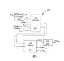
圖1為依據本發明所實施的雙輸出LLC諧振電源轉換器100。FIG. 1 shows a dual output LLC
圖2顯示依據本發明所實施的LLC控制器102。FIG. 2 shows an
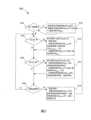
圖3顯示依據本發明的控制方法M01,適用於LLC控制器102。FIG. 3 shows the control method M01 according to the present invention, which is applicable to the
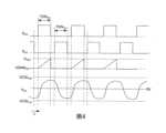
圖4顯示操作於非省電模式下LLC控制器102的一些訊號波形。FIG. 4 shows some signal waveforms of the
圖5顯示圖2中的限制訊號產生器222。FIG. 5 shows the
圖6顯示操作於省電模式下,LLC控制器102的一些訊號波形。FIG. 6 shows some signal waveforms of the
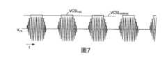
圖7是對應於輸入電源VIN為110V時的電流偵測訊號VCS波形。FIG. 7 is a waveform corresponding to the current detection signal VCS when the input power VIN is 110V.
圖8顯示脫離省電模式的過程中,LLC控制器102的一些信號波形。FIG. 8 shows some signal waveforms of the
在本說明書中,有一些相同的符號,其表示具有相同或是類似之結構、功能、原理的元件,且為業界具有一般知識能力者可以依據本說明書之教導而推知。為說明書之簡潔度考量,相同之符號的元件將不再重述。In this specification, there are some same symbols, which represent elements with the same or similar structure, function, and principle, and can be inferred by those with general knowledge in the industry based on the teaching of this specification. For the sake of brevity in the description, elements with the same symbols will not be repeated.
本發明雖然以雙輸出LLC諧振電源轉換器為例,但本發明並不限於此。在其他實施例中,本發明也可以使用於任何其他類型的諧振電源轉換器或是脈衝寬度調變(pulse-width-modulation,PWM)電源轉換器。Although the present invention takes a dual-output LLC resonant power converter as an example, the present invention is not limited thereto. In other embodiments, the present invention can also be applied to any other type of resonant power converter or pulse-width-modulation (PWM) power converter.
在本發明的一實施例中,一LLC諧振電源轉換器中具有一電源控制器控制一上臂開關以及一下臂開關,兩者連接至由一變壓器與一電容所構成的一諧振電路。該上臂開關與該下臂開關為二功率開關,該變壓器為一電感元件。該電源控制器依據一回饋訊號,控制該上臂開關,而該回饋訊號依據該LLC諧振電源轉換器之一輸出電壓而產生。該電源控制器接收一電流偵測訊號,代表流經該變壓器的一電感電流。In an embodiment of the present invention, an LLC resonant power converter has a power controller controlling an upper arm switch and a lower arm switch, both of which are connected to a resonant circuit formed by a transformer and a capacitor. The upper arm switch and the lower arm switch are two power switches, and the transformer is an inductance element. The power controller controls the upper arm switch according to a feedback signal generated according to an output voltage of the LLC resonant power converter. The power controller is connected toReceive a current detection signal representing an inductor current flowing through the transformer.
當該LLC諧振電源轉換器驅動一重載時,操作於一非省電模式。該電源控制器依據該回饋訊號以及一鋸齒訊號,控制該功率開關之一開啟時間,以使該電源轉換器操作於一電壓控制模式(voltage-control mode)。When the LLC resonant power converter drives a heavy load, it operates in a non-power saving mode. The power controller controls an on time of the power switch according to the feedback signal and a sawtooth signal, so that the power converter operates in a voltage-control mode.
當該LLC諧振電源轉換器驅動無載(也就是沒有負載)時,操作於一叢集模式,作為一省電模式。該電源控制器使該上臂開關連續切換一叢集時間,而維持關閉一中斷時間。該叢集時間具有開頭的一軟進入時間以及結尾的一軟脫出時間。在該軟進入時間與該軟脫出時間內,該電源控制器以一電流控制模式(current-control mode)控制該上臂開關之該開啟時間,也就是比較一電流限制訊號與該電流偵測訊號,來控制該上臂開關。在該軟進入時間內,該電源控制器隨時間增加該電流限制訊號,來實現軟進入(soft burst-in)。在該軟脫出時間內,該電源控制器隨時間降低該電流限制訊號,來實現軟脫出(soft burst-out)。When the LLC resonant power converter is driving no load (ie no load), it operates in a burst mode as a power saving mode. The power controller keeps the upper arm switch continuously switched for a burst time and kept closed for an interrupt time. The cluster time has a soft entry time at the beginning and a soft exit time at the end. During the soft entry time and the soft exit time, the power controller controls the turn-on time of the upper arm switch in a current-control mode, that is, compares a current limit signal with the current detection signal , to control the upper arm switch. During the soft burst-in, the power controller increases the current limit signal over time to implement soft burst-in. During the soft burst time, the power controller reduces the current limit signal over time to achieve soft burst-out.
在本發明的一實施例中,該叢集時間與該中斷時間的合為一固定預設週期,為一叢集頻率的倒數。軟進入與軟脫出可以避免進入與離開該叢集時間時,突然的能量變化而可能造成的令人不適之音頻噪音。In an embodiment of the present invention, the combination of the burst time and the interrupt time is a fixed preset period, which is the reciprocal of a burst frequency. Soft entry and soft exit avoid unpleasant audio noise that may be caused by sudden energy changes when entering and leaving the burst time.
圖1為依據本發明所實施的雙輸出LLC諧振電源轉換器100。LLC諧振電源轉換器100將輸入電源VIN,轉換為輸出電源VO1與VO2,分別對負載1041與1042供電。FIG. 1 shows a dual output LLC
上臂開關HS與下臂開關LS電性串接於輸入電源VIN與接地線GNDIN之間,用來驅動諧振電路RSNT,使諧振電路RSNT震盪。諧振電路RSNT包含有變壓器TF與電容CL。變壓器TF中的主繞組LP與兩個二次側繞組LS1與LS2相互電感耦合。變壓器TF中的電感Lr與Lm表示變壓器TF的主繞組LP的串接漏感與並聯漏感。主繞組LP與電容CL透過連接點ND相串聯。在其他實施例中,諧振電路RSNT可以有不同的架構,並不限於圖1中的結構。上臂開關HS與下臂開關LS都可以控制流經電感Lr的電感電流ILr。The upper arm switch HS and the lower arm switch LS are electrically connected in series between the input power VIN and the ground line GNDIN for driving the resonant circuit RSNT to make the resonant circuit RSNT oscillate. The resonant circuit RSNT includes a transformer TF and a capacitor CL. The primary winding LP in the transformer TF is inductively coupled to the two secondary windings LS1 and LS2. The inductance Lr and Lm in the transformer TF represent the series leakage inductance and the parallel leakage inductance of the main winding LP of the transformer TF. The main winding LP is connected in series with the capacitor CL through the connection point ND. In other embodiments, the resonant circuit RSNT may have different structures, and is not limited to the structure shown in FIG. 1 . Both the upper arm switch HS and the lower arm switch LS can control the inductor current ILr flowing through the inductor Lr.
諧振電路RSNT震盪時,二次側繞組LS1與LS2會產生感應電流ID1與ID2,透過二極體D1與D2的整流,可以在輸出電容CO1與CO2上建立起輸出電源VO1與VO2。When the resonant circuit RSNT oscillates, the secondary side windings LS1 and LS2 will generate induced currents ID1 and ID2 , through the rectification of the diodes D1 and D2, the output power VO1 and VO2 can be established on the output capacitors CO1 and CO2 .
輸出電源VO1與VO2可以透過回饋電路1061與1062,分別產生回饋訊號VFB1與VFB2。LLC控制器102提供上臂控制訊號SHG與下臂控制訊號SLG,分別控制上臂開關HS與下臂開關LS。依據回饋接腳FB1與FB2上的回饋訊號VFB1與VFB2,LLC控制器102可以決定上臂開關HS與下臂開關LS的開啟時間(ON time)TONHG與TONLG,也就是上臂開關HS與下臂開關LS的導通時間。The output power sources VO1 and VO2 can respectively generate feedback signals VFB1 and VFB2 through the
LLC諧振電源轉換器100包含有偵測電路108,包含有電阻RA以及電容CA,彼此連接如同圖1舉例所示。偵測電路108連接到連接點ND,用來偵測諧振電路RSNT中跨於電容CL上的電壓,具以產生電流偵測訊號VCS,可以代表電感電流ILr。電流偵測訊號VCS只是偵測訊號的一種,其他實施例中,偵測電路108可能具有不同的架構,提供不同於電流偵測訊號VCS的偵測訊號。The LLC
在圖1中,位於二次側的電路可以依據系統需求而提供省電訊號PSSEC,透過省電訊號通道1064,在一次側產生叢集訊號VBST,透過叢集接腳(pin)BST,來告知LLC控制器102進入一省電模式。舉例來說,當二次側的電路要整個LLC諧振電源轉換器100進入一省電模式時,透過省電訊號通道1064,使得叢集訊號VBST為大於1V的一個固定值;要進入一非省電模式時,二次側的電路使得叢集訊號VBST小於1V。In Fig. 1, the circuit on the secondary side can provide the power saving signal PSSEC according to the system requirements, through the power saving
舉例來說,回饋電路1061與1062,以及省電訊號通道1064各自具有一光耦合器(photo coupler),用來在隔離的一次側與二次側之間傳遞訊號。For example, each of the
圖2顯示依據本發明所實施的LLC控制器102,包含有上臂控制電路210H與下臂控制電路210L。為簡潔的緣故,圖2中僅僅顯示有關於上臂控制電路210H的細節,而在實施例中,下臂控制電路210L可以共用上臂控制電路210H中部分的電路。FIG. 2 shows the
上臂控制電路210H具有電壓模式控制器212以及電流模式控制器214。在下臂控制訊號SLG關閉下臂開關LS經過一段死區時間(deadtime)後,電壓模式控制器212以及電流模式控制器214各自產生脈衝SVM與SCM,用來開啟上臂開關HS。脈衝SVM與SCM的脈衝寬度個別是電壓模式開啟時間TONVM與電流模式開啟時間TONCM。從圖2可知,上臂開關HS的開啟時間TONHG會是電壓模式開啟時間TONVM與電流模式開啟時間TONCM之間比較短的那一個。The upper
電壓模式控制器212具有,但不限於,鋸齒波產生器216、比較器218、最小開啟時間產生器220、以及遮斷器227。電壓模式控制器212依據回饋訊號VFB2以及鋸齒波產生器216所提供的鋸齒訊號VSAWHG,來產生脈衝SVON,用來控制上臂開關HS的開啟時間TONHG。比較器218比較鋸齒訊號VSAWHG與回饋訊號VFB2。最小開啟時間產生器220提供最小開啟時間脈衝SMIN,定義了最小開啟時間TONMIN。在叢集訊號VBST被認定要操作於一非省電模式時,遮斷器227讓脈衝SVON通過;要操作於一省電模式時,遮斷器227阻擋脈衝SVON。稍後將說明,在非省電模式下,上臂控制訊號SHG的開啟時間TONHG不小於最小開啟時間TONMIN;在省電模式下,上臂控制訊號SHG的開啟時間TONHG不大於最小開啟時間TONMIN。The
電流模式控制器214具有,但不限於,限制訊號產生器222以及比較器223。限制訊號產生器222依據回饋訊號VFB2與叢集訊號VBST,來提供電流限制訊號VCSLHG。比較器223藉由比較電流限制訊號VCSLHG與電流偵測訊號VCS,來產生脈衝SCM。The
圖3顯示依據本發明的控制方法M01,適用於LLC控制器102。FIG. 3 shows the control method M01 according to the present invention, which is applicable to the
請參閱圖2與圖3。步驟S02判斷是否進入省電模式。舉例來說,圖2中的LLC控制器102在叢集訊號VBST大於1V時,認定LLC諧振電源轉換器100要進入省電模式。LLC控制器102也可以在回饋訊號VFB1與VFB2都偏低時,舉例來說,都低於1V時,認定LLC諧振電源轉換器100要進入省電模式。當叢集訊號VBST大於1V時,LLC控制器102依據叢集訊號VBST,提供預設叢集最大電流訊號VCSLHGMAX,用來大致限制省電模式中,最大的電流偵測訊號VCS。在省電模式下,步驟S04、S06接續步驟S02,直到步驟S08確認要脫離省電模式為止。在一實施例中,如果叢集訊號VBST小於1V,而且回饋訊號VFB1與VFB2都偏高,步驟S10接續步驟S02,維持操作在一非省電模式。Please refer to Figure 2 and Figure 3. Step S02 judges whether to enter the power saving mode. For example, the
步驟S10操作於非省電模式下,使得電流模式開啟時間TONCM最大,也使得電壓模式開啟時間TONVM不小於最小開啟時間TONMIN。請參閱圖2與圖4,圖4顯示操作於非省電模式下LLC控制器102的一些訊號波形。在一般非省電模式下,圖2之電流限制訊號VCSLHG很高,上臂開關HS的開啟時間TONHG會是由電壓模式控制器212所產生的脈衝SVON所決定,但不小於最小開啟時間TONMIN。也就是說,開啟時間TONHG大致是由鋸齒訊號VSAWHG與回饋訊號VFB2所決定,如同圖4所顯示。這稱之為電壓控制模式。雖然圖4沒有顯示,下臂開關LS的開啟時間TONLG也是由另一個鋸齒訊號與回饋訊號VFB1所決定。當回饋訊號VFB2固定時,開啟時間TONHG也固定,不隨著輸入電源VIN的電壓值改變而改變。Step S10 operates in the non-power-saving mode, so that the current mode on-time TONCM is maximized, and the voltage-mode on-time TONVM is not less than the minimum on-time TONMIN . Please refer to FIG. 2 and FIG. 4. FIG. 4 shows some signal waveforms of the
圖5顯示圖2中的限制訊號產生器222。限制訊號產生器222具有叢集頻率控制器224、上下數控制器226、上下計數器228、以及數位類比轉換器230。叢集頻率控制器224依據回饋訊號VFB2,提供進入脈衝BI與脫出脈衝BO給上下數控制器226。上下數控制器226依據許多的訊號,來控制上下計數器228,使其上數、下數、或是停止計數。上下計數器228可以有預防溢位(overflow)的功能。當計數CODE到達最大值或最小值時,上下計數器228會自動停止計數,並透過最大值訊號CODEMAX或最小值訊號CODEMIN通知上下數控制器226。數位類比轉換器230轉換計數CODE,成為類比的電流限制訊號VCSLHG。在一實施例中,另一個數位類比轉換器也可以依據計數CODE產生電流限制訊號VCSLLG,來控制下臂開關LS的開啟時間TONLG與電流偵測訊號VCS。FIG. 5 shows the
圖6顯示操作於省電模式下,LLC控制器102的一些訊號波形。如同圖6所示,LLC控制器102以叢集模式來作為省電模式。所謂叢集模式是讓上臂開關HS與下臂開關LS連續切換叢集時間TBST,而後維持關閉中斷時間TBRK,並讓叢集時間TBST與中斷時間TBRK交替出現,如同圖6所示。LLC控制器102使得一叢集時間TBST與一中斷時間TBRK的和大約等於固定的預設週期TPSCYC,等於三角波訊號VRAMP之叢集頻率fBST的倒數。舉例來說,叢集頻率fBST是約800Hz,預設週期TPSCYC約1.25ms。固定的叢集頻率fBST使得變壓器TF所需要供電的裝置,譬如LLC控制器102,可以在每個預設週期TPSCYC內一定會被供應電能,避免LLC控制器102等待時間過長,操作電源耗盡而失效。FIG. 6 shows some signal waveforms of the
如同先前所述,在省電模式下,圖2之遮斷器227阻擋脈衝SVON,所以脈衝SVM的脈衝寬度固定為最小開啟時間TONMIN,因此上臂控制訊號SHG的開啟時間TONHG不大於最小開啟時間TONMIN。As mentioned earlier, in the power-saving mode, the
圖6也顯示了叢集時間TBST具有開頭的軟進入時間TBI以及結尾的軟脫出時間TBO。在軟進入時間TBI內,電流限制訊號VCSLHG隨著時間而增加,上臂開關HS的開啟時間TONHG與下臂開關LS的開啟時間TONLG也隨著開關週期而逐漸增加。在軟脫出時間TBO內,電流限制訊號VCSLHG隨著時間而減少,開啟時間TONHG與開啟時間TONLG也隨著開關週期而逐漸減少。軟進入與軟脫出可以避免進入與離開叢集時間TBST時,突然的能量變化而可能造成的令人不適之音頻噪音。Figure 6 also shows that the burst time TBST has an initial soft entry time TBI and an ending soft exit time TBO . During the soft-entry time TBI , the current limit signal VCSLHG increases with time, and the turn-on time TONHG of the upper arm switch HS and the turn-on time TONLG of the lower arm switch LS also gradually increase with the switching period. During the soft breakout time TBO , the current limit signal VCSLHG decreases with time, and the turn-on time TONHG and the turn-on time TONLG also gradually decrease with the switching cycle. Soft entry and soft exit can avoid unpleasant audio noise that may be caused by sudden energy changes when entering and leaving the burst time TBST .
請參閱圖3、圖5與圖6。圖5中的叢集頻率控制器224內部提供具有固定叢集頻率fBST的三角波訊號VRAMP,並依據回饋訊號VFB2與三角波訊號VRAMP,來決定是否產生進入脈衝BI與脫出脈衝BO(步驟S04與S06)。Please refer to Figure 3, Figure 5 and Figure 6. The
當回饋訊號VFB2高過三角波訊號VRAMP時,叢集頻率控制器224提供進入脈衝BI,開始軟進入時間TBI,執行步驟S12,實現軟進入。步驟S12致能脈衝寬度調變(pulse width modulation,PWM),也就是使得上下臂開關HS與LS開始交錯開啟,開始叢集時間TBST。步驟S12也使得電流限制訊號VCSLHG開始隨著時間而增加,直到大於等於叢集最大電流訊號VCSLHGMAX。步驟S12也使得上臂開關HS的開啟時間TONHG不大於最小開啟時間TONMIN。舉例來說,當收到進入脈衝BI時,圖5中的上下數控制器226以上臂控制訊號SHG作為時脈,開始使得上下計數器228上數,逐漸增加計數CODE。數位類比轉換器230轉換計數CODE,成為類比的電流限制訊號VCSLHG。所以電流限制訊號VCSLHG將會隨著時間而增加。當上下數控制器226發現電流限制訊號VCSLHG大於等於叢集最大電流訊號VCSLHGMAX(對應到叢集訊號VBST)時,上下數控制器226使上下計數器228停止上數,結束軟進入時間TBI。之後,計數CODE與電流限制訊號VCSLHG都會維持不變,如同圖6所示。圖2之遮斷器227阻擋脈衝SVON,使得上臂控制訊號SHG的開啟時間TONHG不大於最小開啟時間TONMIN。When the feedback signal VFB2 is higher than the triangular wave signal VRAMP, the
當回饋訊號VFB2低過三角波訊號VRAMP時,叢集頻率控制器224提供脫出脈衝BO,開始軟脫出時間TBO,執行步驟S14,實現軟脫出。步驟S14使得上臂開關HS的開啟時間TONHG不大於最小開啟時間TONMIN;使得電流限制訊號VCSLHG開始隨著時間而減少,直到小於等於一預設最低電流訊號;以及,在電流限制訊號VCSLHG小於等於一預設最低電流訊號時,禁能PWM,也就是使得上下臂開關HS與LS停止交錯開啟,或是都維持關閉。舉例來說,圖2之遮斷器227阻擋脈衝SVON,使得上臂控制訊號SHG的開啟時間TONHG不大於最小開啟時間TONMIN。當收到脈衝BO時,圖5中的上下數控制器226以上臂控制訊號SHG作為時脈,開始使得上下計數器228下數,逐漸減少計數CODE。所以電流限制訊號VCSLHG將會隨著時間而減少。當上下數控制器226透過最小碼訊號CODEMIN,發現計數CODE已經到達最低時,就使得上下計數器228停止計數,同時禁能PWM,使得上下臂開關HS與LS都維持關閉,開始進入圖6中的中斷時間TBRK。最低的計數CODE所對應的電流限制訊號VCSLHG,就是預設最低電流訊號。When the feedback signal VFB2 is lower than the triangular wave signal VRAMP, the
在軟進入時間TBI之後,而下一個軟脫出時間TBO之前,PWM致能中,上臂控制訊號SHG的開啟時間TONHG大致由不變的電流限制訊號VCSLHG所決定,但不大於最小開啟時間TONMIN。在中斷時間TBRK內,也就是一軟脫出時間TBO之後,一軟進入時間TBI之前,PWM禁能中,上下臂開關HS與LS都維持關閉,如同圖6所示。After the soft-in time TBI and before the next soft-out time TBO , during PWM enabling, the on-time TONHG of the upper arm control signalSHG is roughly determined by the constant current limit signal VCSLHG , but not greater than Minimum turn-on time TONMIN . During the break time TBRK , that is, after a soft-out time TBO and before a soft-in time TBI , both the upper and lower arm switches HS and LS are kept closed during PWM disable, as shown in FIG. 6 .
圖6顯示了電流偵測訊號VCS持續會頂到電流限制訊號VCSLHG,表示上臂控制訊號SHG的開啟時間TONHG大致都是由電流模式控制器214所限制,但本發明不限於此。圖7顯示在叢集時間TBST內,電流偵測訊號VCS可能會沒頂到電流限制訊號VCSLHG。如同先前所述的,在省電模式下,上臂控制訊號SHG的開啟時間TONHG將不大於電壓模式控制器212中所定義的最小開啟時間TONMIN。因此,有可能在軟進入時間TBI的最後階段,電流模式控制器214所定義的電流模式開啟時間TONCM已經超過了最小開啟時間TONMIN,那開啟時間TONHG就僅僅能夠維持在最小開啟時間TONMIN。換言之,電流偵測訊號VCS會沒有頂到電流限制訊號VCSLHG,如同圖7所示。舉例來說,圖6與7分別是對應於輸入電源VIN為237V與110V時的信號波形。高輸入電源VIN比較容易使得電流偵測訊號VCS頂到電流限制訊號VCSLHG。6 shows that the current detection signal VCS will continue to reach the current limit signal VCSLHG , indicating that the on-time TONHG of the upper arm control signalSHG is generally limited by the
步驟S08判斷是否脫離省電模式。舉例來說,圖2中的LLC控制器102在叢集訊號VBST小於1V時,而且回饋訊號VFB1與VFB2都大於1V時,認定LLC諧振電源轉換器100要脫離省電模式。如果沒有要脫離省電模式,步驟S04與S06繼續執行;如果確定要脫離省電模式,步驟S16接續執行。Step S08 determines whether to exit the power saving mode. For example, the
步驟S16等於是省電模式到非省電模式的切換過程。首先,步驟S16致能PWM,也就是使得上下臂開關HS與LS開始交錯開啟。在一實施例中,上下數控制器226執行步驟S16,使得上下計數器228先行下數,計數CODE已經到達最低(可以由最小值訊號CODEMIN得知)時,使得上下計數器228開始上數,直到計數CODE達到最高(可以由最大值訊號CODEMAX得知),才停止上下計數器228計數。圖8顯示在時間t0時,叢集訊號VBST掉到大約等於0V,所以步驟S16開始執行,脫離省電模式。如同圖8所示,因為上下計數器228先下數,而後上數,所以電流限制訊號VCSLHG先階梯的減少。大約到0V後,就階梯的增加,最後停留在計數CODE之最高值所對應的一固定值。在圖8中,電流偵測訊號VCS的峰值一開始是追隨著電流限制訊號VCSLHG的變化,但是受限於回饋訊號VFB2所決定的開啟時間TONHG(也就是電壓控制模式控制下的開啟時間TONHG),所以最後電流偵測訊號VCS的峰值就不會追隨電流限制訊號VCSLHG。Step S16 is equal to the switching process from the power saving mode to the non-power saving mode. First, step S16 enables PWM, that is, makes the upper and lower arm switches HS and LS start to be turned on alternately. In one embodiment, the up-down
儘管在以上實施例中,電流限制訊號VCSLHG的增加與減少,都是由上下計數器228配合數位類比轉換器230所產生,但是本發明不限於此。在一實施例中,限制訊號產生器222可以以一定電流源對一電容來充電或是放電,所產生的電容電壓來做為電流限制訊號VCSLHG。舉例來說,在軟進入時間TBI中,一電流源對一電容充電,所以該電容的電容電壓逐漸上升,來做為電流限制訊號VCSLHG,實現軟進入。在軟脫出時間TBO內,另一電流源對該電容放電,所以該電容的電容電壓逐漸下降,來做為電流限制訊號VCSLHG,實現軟脫出。Although in the above embodiments, the increase and decrease of the current limit signal VCSLHG are both generated by the up-
本發明的實施例中,因為軟進入與軟脫出,所以可能可以在省電模式下,不會有惱人的音頻噪音。而且,固定的叢集頻率可以使得LLC控制器102的操作電源比較穩定。In the embodiment of the present invention, because of soft entry and soft exit, it may be possible to have no annoying audio noise in power saving mode. Moreover, the fixed burst frequency can make the operating power of the
以上所述僅為本發明之較佳實施例,凡依本發明申請專利範圍所做之均等變化與修飾,皆應屬本發明之涵蓋範圍。The above descriptions are only preferred embodiments of the present invention, and all equivalent changes and modifications made according to the scope of the patent application of the present invention shall fall within the scope of the present invention.
S02、S04、S06、S08、S10、S12、S14、S16:步驟S02, S04, S06, S08, S10, S12, S14, S16: steps
Claims (10)
Translated fromChinesePriority Applications (2)
| Application Number | Priority Date | Filing Date | Title |
|---|---|---|---|
| TW110144130ATWI796013B (en) | 2021-11-26 | 2021-11-26 | Power controller and control method for power converter |
| US17/818,794US12047005B2 (en) | 2021-11-26 | 2022-08-10 | Power controller and control method with functions of soft burst-in and soft burst-out |
Applications Claiming Priority (1)
| Application Number | Priority Date | Filing Date | Title |
|---|---|---|---|
| TW110144130ATWI796013B (en) | 2021-11-26 | 2021-11-26 | Power controller and control method for power converter |
Publications (2)
| Publication Number | Publication Date |
|---|---|
| TWI796013Btrue TWI796013B (en) | 2023-03-11 |
| TW202322539A TW202322539A (en) | 2023-06-01 |
Family
ID=86499452
Family Applications (1)
| Application Number | Title | Priority Date | Filing Date |
|---|---|---|---|
| TW110144130ATWI796013B (en) | 2021-11-26 | 2021-11-26 | Power controller and control method for power converter |
Country Status (2)
| Country | Link |
|---|---|
| US (1) | US12047005B2 (en) |
| TW (1) | TWI796013B (en) |
Cited By (1)
| Publication number | Priority date | Publication date | Assignee | Title |
|---|---|---|---|---|
| WO2025189437A1 (en)* | 2024-03-14 | 2025-09-18 | 台达电子工业股份有限公司 | Interleaved flying capacitor multi-level converter |
Families Citing this family (3)
| Publication number | Priority date | Publication date | Assignee | Title |
|---|---|---|---|---|
| TWI806552B (en)* | 2021-12-06 | 2023-06-21 | 通嘉科技股份有限公司 | Control method and power controller for power factor correction |
| TWI796208B (en)* | 2022-04-21 | 2023-03-11 | 通嘉科技股份有限公司 | Control method and power controller in use of primary-side-regulation power converter |
| TWI860256B (en)* | 2024-03-14 | 2024-10-21 | 台達電子工業股份有限公司 | Interleaved flying capacitor multi-level converter |
Citations (4)
| Publication number | Priority date | Publication date | Assignee | Title |
|---|---|---|---|---|
| TW201218595A (en)* | 2010-10-18 | 2012-05-01 | Richpower Microelectronics | Circuit and method for sub-harmonic elimination of a power converter |
| TW201310878A (en)* | 2011-08-26 | 2013-03-01 | Richtek Technology Corp | Frequency jittering control circuit and method for a PFM power supply |
| CN103597721A (en)* | 2011-05-13 | 2014-02-19 | 罗姆股份有限公司 | Non-isolated step-down switching regulator, control circuit therefor, electronic device, and AC adapter |
| US20150381041A1 (en)* | 2014-06-27 | 2015-12-31 | Yun-Shan Chang | Low-light solar boost converter and control method therefor |
Family Cites Families (26)
| Publication number | Priority date | Publication date | Assignee | Title |
|---|---|---|---|---|
| JPH06175741A (en)* | 1992-12-07 | 1994-06-24 | Mitsubishi Electric Corp | Static reactive power generating device |
| WO2005041393A2 (en)* | 2003-10-24 | 2005-05-06 | Pf1, Inc. | Method and system for power factor correction |
| WO2007011332A1 (en)* | 2005-07-15 | 2007-01-25 | Semiconductor Components Industries, L.L.C. | Power supply controller and method therefor |
| KR101489962B1 (en)* | 2008-07-15 | 2015-02-04 | 페어차일드코리아반도체 주식회사 | Power converter, its switching control device and driving method thereof |
| CN101552563B (en)* | 2009-03-20 | 2011-09-14 | Bcd半导体制造有限公司 | Device and method for controlling constant-current output in switch power supply |
| CN102570837B (en)* | 2012-02-28 | 2014-09-03 | 矽力杰半导体技术(杭州)有限公司 | Constant voltage constant current control circuit and control method thereof |
| US9143043B2 (en)* | 2012-03-01 | 2015-09-22 | Infineon Technologies Ag | Multi-mode operation and control of a resonant converter |
| TWI470906B (en)* | 2012-07-04 | 2015-01-21 | Leadtrend Tech Corp | Constant current control units and control methods thereof for primary side control |
| TWI583114B (en)* | 2012-11-27 | 2017-05-11 | 通嘉科技股份有限公司 | Power controller with over power protection |
| US9318966B2 (en)* | 2013-06-26 | 2016-04-19 | Stmicroelectronics S.R.L. | Method of controlling a switching converter in burst mode and related controller for a switching converter |
| US9595867B2 (en)* | 2014-10-02 | 2017-03-14 | Texas Instruments Incorporated | System and method to improve standby efficiency of LLC converter |
| US10277130B2 (en)* | 2015-06-01 | 2019-04-30 | Microchip Technolgoy Incorporated | Primary-side start-up method and circuit arrangement for a series-parallel resonant power converter |
| CN105375768B (en)* | 2015-10-19 | 2018-03-06 | 成都芯源系统有限公司 | Capacitive mode protection method and capacitive mode control circuit of resonant converter |
| TWI601368B (en)* | 2016-01-22 | 2017-10-01 | 通嘉科技股份有限公司 | Switched mode power supplies capable of operating at valley switching, and relevant control methods |
| TWI605671B (en)* | 2016-09-01 | 2017-11-11 | 通嘉科技股份有限公司 | Control methods and switching mode power supplies with improved dynamic response and reduced switching loss |
| TWI678059B (en)* | 2018-05-14 | 2019-11-21 | 通嘉科技股份有限公司 | Switching-mode power supplies and power controllers capable of jittering switching frequency |
| TWI672894B (en)* | 2018-07-25 | 2019-09-21 | 通嘉科技股份有限公司 | Power controllers and control methods thereof |
| CN111684697B (en)* | 2018-08-02 | 2023-08-01 | 富士电机株式会社 | Control device for switching power supply device |
| TWI672896B (en)* | 2018-09-28 | 2019-09-21 | 通嘉科技股份有限公司 | Active clamp flyback converters and control methods thereof |
| US11081966B2 (en)* | 2018-12-13 | 2021-08-03 | Power Integrations, Inc. | Multi zone secondary burst modulation for resonant converters |
| CN110752750B (en)* | 2019-10-14 | 2021-09-10 | 成都芯源系统有限公司 | Resonant converter and control circuit and control method thereof |
| CN112769322B (en)* | 2019-11-05 | 2022-05-24 | 台达电子企业管理(上海)有限公司 | Inverter and soft start method thereof |
| TWI717247B (en)* | 2020-03-30 | 2021-01-21 | 通嘉科技股份有限公司 | Power controller and control method for llc resonant converter |
| US11404863B2 (en)* | 2020-04-07 | 2022-08-02 | Leadtrend Technology Corporation | Power supplies with limited power protection and relevant control methods |
| TWI813059B (en)* | 2021-11-10 | 2023-08-21 | 通嘉科技股份有限公司 | Llc controller and control method for power converter |
| TWI796208B (en)* | 2022-04-21 | 2023-03-11 | 通嘉科技股份有限公司 | Control method and power controller in use of primary-side-regulation power converter |
- 2021
- 2021-11-26TWTW110144130Apatent/TWI796013B/enactive
- 2022
- 2022-08-10USUS17/818,794patent/US12047005B2/enactiveActive
Patent Citations (4)
| Publication number | Priority date | Publication date | Assignee | Title |
|---|---|---|---|---|
| TW201218595A (en)* | 2010-10-18 | 2012-05-01 | Richpower Microelectronics | Circuit and method for sub-harmonic elimination of a power converter |
| CN103597721A (en)* | 2011-05-13 | 2014-02-19 | 罗姆股份有限公司 | Non-isolated step-down switching regulator, control circuit therefor, electronic device, and AC adapter |
| TW201310878A (en)* | 2011-08-26 | 2013-03-01 | Richtek Technology Corp | Frequency jittering control circuit and method for a PFM power supply |
| US20150381041A1 (en)* | 2014-06-27 | 2015-12-31 | Yun-Shan Chang | Low-light solar boost converter and control method therefor |
Cited By (1)
| Publication number | Priority date | Publication date | Assignee | Title |
|---|---|---|---|---|
| WO2025189437A1 (en)* | 2024-03-14 | 2025-09-18 | 台达电子工业股份有限公司 | Interleaved flying capacitor multi-level converter |
Also Published As
| Publication number | Publication date |
|---|---|
| TW202322539A (en) | 2023-06-01 |
| US12047005B2 (en) | 2024-07-23 |
| US20230170781A1 (en) | 2023-06-01 |
Similar Documents
| Publication | Publication Date | Title |
|---|---|---|
| TWI796013B (en) | Power controller and control method for power converter | |
| US11870350B2 (en) | Switched-mode power controller with multi-mode startup | |
| US10658934B2 (en) | Quasi-resonant converter with efficient light-load operation and method therefor | |
| US8339817B2 (en) | Method of operating a resonant power converter and a controller therefor | |
| TWI672896B (en) | Active clamp flyback converters and control methods thereof | |
| US7852640B2 (en) | System and method for providing control for switch-mode power supply | |
| TWI687034B (en) | Active clamp flyback converter capable of switching operation modes | |
| US9531279B2 (en) | Power supply controller with minimum-sum multi-cycle modulation | |
| TWI489745B (en) | Power controllers, power supplies and control methods therefor | |
| US20090201705A1 (en) | Energy converting apparatus, and semiconductor device and switching control method used therein | |
| JP2003324956A (en) | Method of controlling series resonant bridge inverter circuit and the circuit | |
| CN113632354B (en) | Soft Start of Resonant Converter | |
| CN112532066A (en) | Novel zero-voltage switching control circuit and method and voltage converter | |
| CN111030479B (en) | Active-clamp flyback power converter and associated control method | |
| CN110557022B (en) | Method for controlling PSFB converter and PSFB converter | |
| CN114400899A (en) | Novel zero-voltage switching control circuit and method and voltage converter | |
| TWI813059B (en) | Llc controller and control method for power converter | |
| TWI753801B (en) | Control methods for changing minimum on-time of synchronous rectifier and related synchronous rectifier controllers | |
| KR102845690B1 (en) | Dc-dc converter and method for controlling the same | |
| CN116264435A (en) | Power supply controller with soft entry and soft exit and control method | |
| TWI839936B (en) | Flyback power converters and control methods thereof | |
| CN116191362A (en) | Control method of power converter and LLC controller | |
| TW202516832A (en) | Quasi-resonant flyback converter operating with a constant switching frequency and valley-switching controller therefor | |
| JP2010057207A (en) | Switching power supply unit | |
| KR100402530B1 (en) | Soft switching mode power supply apparatus |