TWI795941B - Board-to-Board Positioning Device - Google Patents
Board-to-Board Positioning DeviceDownload PDFInfo
- Publication number
- TWI795941B TWI795941BTW110137595ATW110137595ATWI795941BTW I795941 BTWI795941 BTW I795941BTW 110137595 ATW110137595 ATW 110137595ATW 110137595 ATW110137595 ATW 110137595ATW I795941 BTWI795941 BTW I795941B
- Authority
- TW
- Taiwan
- Prior art keywords
- base
- holes
- board
- shaft
- limiting
- Prior art date
Links
- 230000000149penetrating effectEffects0.000claimsabstractdescription6
- 238000003825pressingMethods0.000claimsdescription17
- 125000006850spacer groupChemical group0.000claimsdescription7
- 239000000725suspensionSubstances0.000claimsdescription3
- 238000000034methodMethods0.000description5
- 238000006073displacement reactionMethods0.000description2
- 230000000694effectsEffects0.000description2
- 238000012986modificationMethods0.000description2
- 230000004048modificationEffects0.000description2
- 238000012552reviewMethods0.000description2
- 230000007812deficiencyEffects0.000description1
- 238000010586diagramMethods0.000description1
- 238000005304joiningMethods0.000description1
- 238000012423maintenanceMethods0.000description1
- 230000007257malfunctionEffects0.000description1
- 238000004519manufacturing processMethods0.000description1
- 238000012545processingMethods0.000description1
- 239000007787solidSubstances0.000description1
Images


Landscapes
- Mechanical Control Devices (AREA)
- Jigs For Machine Tools (AREA)
- Control Of Motors That Do Not Use Commutators (AREA)
- Paper (AREA)
- Waveguide Aerials (AREA)
Abstract
Translated fromChineseDescription
Translated fromChinese本發明係提供一種板對板定位裝置,尤指方便識別呈鎖定或解鎖狀態之定位裝置,係於基座外部罩覆有調整旋鈕,可供旋動調整旋鈕而驅動基座內部限位球體位移,並透過調整旋鈕外緣所設識別部,達到方便操作定位裝置進行鎖定或解鎖之目的。The present invention provides a board-to-board positioning device, especially a positioning device that is convenient for identifying the locked or unlocked state. It is covered with an adjustment knob on the outside of the base, which can be used to rotate the adjustment knob to drive the displacement of the limit ball inside the base. , and through the identification part set on the outer edge of the adjustment knob, it is convenient to operate the positioning device for locking or unlocking.
按,一般之板材(板對板)於組裝、接合時,係利用具有旋鈕、套環及螺釘之定位螺絲予以鎖接,其係將螺釘、套環先固定於外層之面板上,先旋動旋鈕而供螺釘鎖入內層之面板形成預置定位,再利用手工具將螺釘鎖緊後,則使外層面板與內層面板鎖接定成一體,此種多層板體之鎖接模式,為可運用於工作母機或者其他板對板連接之板材所使用;然該等工作母機需要運用板材進行鎖接處,大都為動力裝置或者速率調整裝置等位置,而各種動力裝置、速率調整裝置係位於機具殼體所形成的空間內部,即可利用板材活動組裝、鎖接、拆卸方式,當動力裝置發生當機或故障、損壞時,或者速率調整裝置進行速率之變化、調整時,將板材卸除以進行相關的維修、調整作業,而板材係透過複數定位螺絲予以鎖固,所以在拆卸過程中容易造成定位螺絲的脫落、遺失,則無法將板材重新再鎖固回原位,影響組裝、拆作業的不便與麻煩,即有業者為解決鎖固螺絲容易遺失的缺點,研發出藉由套帽、螺桿部及定位座所組成之固定裝置,係先將固定裝置的定位座扣固於板材之穿孔內,再利用螺桿部鎖接於另一板材上形成固定,並於使用者卸下板材時,固定裝置仍可透過定位座固定於板材之穿孔內,而不致發生固定裝置脫落或遺失的情況,但在組裝過程仍必須透過使用者施力操作或採用手工具(如起子或扳手等)等,予以操控固定裝置之鎖固或拆卸等作業,實際應用時仍存在諸多缺失與困擾。Press, when assembling and joining general boards (board-to-board), they are locked by positioning screws with knobs, collars and screws. The screws and collars are first fixed on the outer panel and then rotated first. The knob and the panel for the screw to be locked into the inner layer form a preset position, and then the screw is locked with a hand tool, so that the outer panel and the inner panel are locked into one body. The locking mode of this multi-layer board body is It can be used for working machines or other board-to-board connections; however, these working machines need to use plates for locking, most of which are power devices or speed adjustment devices, and various power devices and speed adjustment devices are located in the Inside the space formed by the tool shell, the plate can be assembled, locked, and disassembled. When the power device crashes, malfunctions, or is damaged, or the speed adjustment device changes or adjusts the speed, the plate can be removed. In order to carry out related maintenance and adjustment operations, and the board is locked by a plurality of positioning screws, so it is easy to cause the positioning screws to fall off or be lost during the disassembly process, and the board cannot be re-locked back to its original position, which will affect the assembly and disassembly. The inconvenience and trouble of operation, that is, some operators solve the problem of locking screwsThe shortcoming of being easily lost, a fixing device composed of a cap, a screw part and a positioning seat has been developed. First, the positioning seat of the fixing device is fastened in the perforation of the plate, and then the screw part is used to lock it on another plate. Form a fixation, and when the user removes the board, the fixing device can still be fixed in the perforation of the board through the positioning seat, so that the fixing device will not fall off or be lost, but it must still be operated by the user during the assembly process or Using hand tools (such as screwdrivers or wrenches, etc.) to control the locking or dismounting of the fixing device still has many shortcomings and problems in practical application.
而應用於二相對板材以鎖接固定方式結合,在現今講究模組化的大量生產、加工效率的要求下,使得利用螺絲進行繁瑣的人工組裝程序,則將嚴重影響到廠商出貨的進度,且螺絲因體積小、則於鎖固二板材的過程中容易遺失,且會因為螺絲鎖固位置的螺孔尺寸的差異或螺孔齒數、螺距的不符,造成組裝、對位或鎖固時的困難,且二相對板材間可供操作螺絲的空間相當窄小,即於進行螺絲組裝、拆卸時容易受到周邊物體阻礙的缺失,不僅相當耗費工時與不便之外,也將會導致整體產生成本提高,造成業者負擔增加。However, when two opposite plates are combined by locking and fixing, under the requirements of modular mass production and processing efficiency today, the cumbersome manual assembly process using screws will seriously affect the progress of the manufacturer's shipment. In addition, due to the small size of the screw, it is easy to lose during the process of locking the second plate, and because of the difference in the size of the screw hole at the position where the screw is locked, or the number of teeth and the pitch of the screw hole do not match, resulting in misalignment during assembly, alignment or locking. Difficult, and the space available for operating screws between the two opposite plates is quite narrow, that is, when the screws are assembled and disassembled, they are easily obstructed by surrounding objects, which not only consumes man-hours and inconvenience, but also leads to overall cost increase, resulting in an increase in the burden on the industry.
是以,如何解決目前板材鎖固時所應用之固定裝置,容易被誤旋轉而鬆動、脫離之問題與困擾,且固定裝置於進行組裝時需施力或應用手工具之麻煩與不便,即為從事此行業之相關廠商所亟欲研究改善之方向所在者。Therefore, how to solve the problems and troubles that the fixing device used in the current board locking is easy to be loosened and disengaged by wrong rotation, and the fixing device needs to apply force or use hand tools when assembling. Relevant manufacturers engaged in this industry are eager to study the direction of improvement.
故,發明人有鑑於上述之問題與缺失,乃搜集相關資料,經由多方評估及考量,並以從事於此行業累積之多年經驗,經由不斷創設及修改,始設計出此種板對板定位裝置的發明專利誕生者。Therefore, in view of the above-mentioned problems and deficiencies, the inventor collected relevant information, evaluated and considered in many ways, and based on years of experience accumulated in this industry, through continuous creation and modification, he designed this board-to-board positioning device The invention patent birther.
本發明之主要目的乃在於該板對板定位裝置,該基座內部貫通之軸孔、其內壁面垂直方向設有朝外部貫通之二相對式通孔、且各通孔內分別裝置限位球體,而基座外部一側設有連接部、另側限位部設有二相對式之限位槽對位於二相對式之通孔外部,再由調整旋鈕內部操作空間穿設於基座外,則基座一側連接部露出操作空間外側,並於操作空間內之滑移壁面對位於該通孔、驅動部則對位於限位部,且滑移壁面設有不同內徑之抵壓側、退離側可抵推二相對之限位球體進、出各通孔,該驅動部凸設有至少一個或一個以上之卡制凸體沿限位部旋動滑移而進、出其中一限位槽處,相對卡制凸體於調整旋鈕外部設有標識部,達到方便操作定位裝置鎖定或解鎖之目的。The main purpose of the present invention is the plate-to-plate positioning device, the shaft hole penetrating inside the base, the inner wall surface is vertically provided with two opposite through holes penetrating to the outside, and each through hole is respectively equipped with a limit ball , and the outer side of the base is provided with a connecting part, and the other side of the limit part is provided with two relative limit grooves, which are located outside the two relative through holes, and then the inner operating space of the adjustment knob is passed outside the base. Then the connecting part on one side of the base is exposed outside the operating space, and the sliding wall in the operating space is located in the through hole, and the driving part is located in the limit part, and the sliding wall is provided with pressure sides with different inner diameters. , The retreating side can push two opposite limiting spheres into and out of each through hole, and the driving part is provided with at least one or more locking protrusions to slide in and out of one of them along the limiting part. At the position of the limit groove, there is an identification part on the outside of the adjustment knob relative to the clamping convex body, so as to achieve the purpose of conveniently operating the locking or unlocking of the positioning device.
本發明之又一目的乃在於該基座係於內部軸孔的至少二相對壁面設有朝垂直軸孔方向往外貫通至少二相對之通孔,各通孔內分別活動裝設限位球體,而基座外部一側限位部分別設有二相對限位槽對位於至少二相對通孔,且該二限位槽係供該卡制凸體做一滑移進出,並於二相對限位槽的相鄰預設角度另二相對側分別設有暫停卡槽,且該二暫停卡槽係供該卡制凸體做一滑移進出,則預設角度為可介於60°~120°之間,而較佳之預設角度則可為90°,且基座一側連接部係包括供限位墊圈套設之套接環、供預設第一板材以第一定位孔嵌設定位之嵌固槽。Yet another object of the present invention is that the base is connected to at least two opposite walls of the inner shaft hole and is provided with at least two opposite through holes extending outwards in the direction perpendicular to the shaft hole, and each through hole is respectively equipped with a limiting sphere for movement, and The limiting part on one side of the base is respectively provided with two relative limiting grooves, which are located at least two relative through holes, and the two limiting grooves are used for the locking convex body to slide in and out, and are connected to the two relative limiting grooves. The other two opposite sides of the adjacent preset angle are respectively provided with pause card slots, and the two pause card slots are for the card convex body to slide in and out, then the preset angle can be between 60°~120° between, and a better preset angle can be 90°, and the connection part on one side of the base includes a sleeve ring for the limit washer to be sleeved, and an embedding ring for the preset first plate to be embedded in the first positioning hole. solid groove.
本發明之再一目的乃在於該調整旋鈕內部操作空間係包括二相鄰堆疊之滑移壁面、驅動部,以供基座一側連接部由驅動部穿入經過滑移壁面而露出調整旋鈕外側,且滑移壁面設有較小內徑之抵壓側對位於驅動部之卡制凸體處,相鄰抵壓側設有較大內徑之退離側,調整旋鈕外部設有呈凸桿體之標識部、呈圓柱體之標識部或呈板體狀之標識部等。Another object of the present invention is that the internal operating space of the adjustment knob includes two adjacent stacked sliding walls and a driving part, so that the connecting part on one side of the base can pass through the sliding wall from the driving part to expose the outside of the adjustment knob. , and the sliding wall is provided with a pressing side with a smaller inner diameter facing the clamping convex body of the driving part, and the adjacent pressing side is provided with a retreating side with a larger inner diameter, and the outside of the adjustment knobThere is a marking part in the form of a convex rod, a marking part in the shape of a cylinder, or a marking part in the shape of a plate, etc.
本發明之另一目的乃在於該定位裝置進一步包括基座、調整旋鈕及穿置在基座的軸孔內之軸座,該基座內部貫通之軸孔、其內壁面垂直方向設有朝外部貫通之至少一個或一個以上之通孔、且至少一個或一個以上之通孔內裝置限位球體,而基座外部一側設有連接部、另側限位部設有至少一個或一個以上之限位槽對位於通孔處,再由調整旋鈕內部操作空間穿設於基座外,則基座一側連接部露出操作空間外側,並於操作空間內之滑移壁面對位於該通孔、驅動部則對位於限位部,且滑移壁面設有不同內徑之抵壓側、退離側可抵推至少一個或一個以上之限位球體進、出至少一個或一個以上之通孔處,該驅動部凸設有至少一個或一個以上之卡制凸體沿限位部旋動滑移而進、出限位槽處,相對卡制凸體於調整旋鈕外部設有標識部,該軸座係包括座體、自座體一側向外延伸之軸桿,則可供該基座的軸孔套設、穿置於軸桿處,且座體位於基座外部,該軸桿懸空側設有止擋體通過至少一個或一個以上之通孔處,再於止擋體與座體之間的軸桿處設有凹環槽,供對位於至少一個或一個以上之通孔、並供位於各通孔內之各限位球體活動卡制或退離該凹環槽處,達到方便操作定位裝置鎖定或解鎖之目的。Another object of the present invention is that the positioning device further includes a base, an adjustment knob, and a shaft seat inserted in the shaft hole of the base. There are at least one or more through holes through, and at least one or more through holes are equipped with limiting balls, and the outer side of the base is provided with a connecting part, and the other side of the limiting part is provided with at least one or more The limit groove is located at the through hole, and the inner operating space of the adjustment knob is passed through the outside of the base, so that the connecting part on one side of the base is exposed outside the operating space, and the sliding wall in the operating space is located in the through hole , The driving part is opposite to the limit part, and the sliding wall is provided with different inner diameters of the pressure side and the retreat side, which can push at least one or more limit spheres into and out of at least one or more through holes At the position, the driving part is protruded with at least one or more clamping protrusions that rotate and slide along the limit part to enter and exit the position of the limit groove. Relative to the clamping protrusions, an identification part is provided outside the adjustment knob. The shaft seat system includes a seat body and a shaft extending outward from one side of the seat body, which can be used for the shaft hole of the base to be sleeved and passed through the shaft rod, and the seat body is located outside the base. There is a place where the stop body passes through at least one or more through holes, and a concave ring groove is provided at the shaft between the stop body and the seat body, for at least one or more through holes, and for The limiting spheres located in each through hole are movably clamped or withdrawn from the concave ring groove, so as to achieve the purpose of conveniently operating the positioning device to lock or unlock.
本發明之又一目的乃在於該軸座之座體外徑係大於基座外徑且小於調整旋鈕外徑,自座體一側向外延伸之軸桿的外徑小於軸孔,且相對軸桿於座體另側設有銜接側,為可供預設第二板材的第二定位孔嵌固定位,軸座於座體一側向外延伸之軸桿,其懸空側所設之止擋體一側設有呈錐狀傾斜之第一導斜面延伸至凹環槽處,相對第一導斜面於止擋體另側設有呈錐狀向外傾斜之第二導斜面。Another object of the present invention is that the outer diameter of the shaft seat is larger than the outer diameter of the base and smaller than the outer diameter of the adjustment knob, and the outer diameter of the shaft extending outward from one side of the seat is smaller than the shaft hole, and is opposite to the shaft. There is a connection side on the other side of the seat body, which can be used to insert and fix the second positioning hole of the second plate, the shaft seat extends outward from one side of the seat body, and the stopper body is set on the suspended side One side is provided with a first guide slope that is inclined in a conical shape and extends to the concave ring groove, opposite to the first guide slope on the other side of the stop bodyThere is a second guide inclined surface that is tapered outwards.
1:基座1: Base
10:軸孔10: shaft hole
101:通孔101: Through hole
1011:抵擋環緣1011: Resist the ring
11:限位球體11:Limiting sphere
12:連接部12: Connecting part
121:套接環121: sleeve ring
1210:環孔1210: ring hole
1211:限位墊圈1211: limit washer
122:嵌固槽122: Embedded groove
13:限位部13: limit part
130:限位槽130: limit slot
131:暫停卡槽131: Pause card slot
2:調整旋鈕2: Adjustment knob
20:操作空間20: Operation space
21:滑移壁面21: Sliding wall
211:抵壓側211: pressure side
212:退離側212: Departure side
22:驅動部22: Drive Department
221:卡制凸體221: card convex body
23:標識部23: Logo Department
3:第一板材3: The first plate
30:第一定位孔30: The first positioning hole
4:軸座4: shaft seat
41:座體41: seat body
411:銜接側411: Connection side
42:軸桿42: Shaft
420:凹環槽420: concave ring groove
421:止擋體421: stop body
4211:第一導斜面4211: The first guide slope
4212:第二導斜面4212: The second guide slope
5:第二板材5: Second plate
50:第二定位孔50: The second positioning hole
[第1圖]係為本發明之立體外觀圖。[Fig. 1] is a three-dimensional appearance view of the present invention.
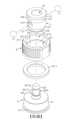
[第2圖]係為本發明之立體分解圖。[Fig. 2] is a three-dimensional exploded view of the present invention.
[第3圖]係為本發明另一視角之立體分解圖。[Fig. 3] is an exploded perspective view of another perspective of the present invention.
[第4圖]係為本發明之側視剖面圖。[Fig. 4] is a side sectional view of the present invention.
[第5圖]係為本發明軸座及調整旋鈕旋動前之俯視圖。[Fig. 5] is a top view of the shaft seat and the adjustment knob of the present invention before turning.
[第6圖]係為本發明軸座及調整旋鈕旋動後之俯視圖。[Fig. 6] is a top view of the shaft seat and the adjustment knob of the present invention after being turned.
[第7圖]係為本發明較佳實施例之側視剖面圖。[Fig. 7] is a side sectional view of a preferred embodiment of the present invention.
為達成上述目的與功效,本發明所採用之技術手段及其構造、實施之方法等,茲繪圖就本發明之較佳實施例詳加說明其特徵與功能如下,俾利完全瞭解。In order to achieve the above-mentioned purpose and effect, the technical means adopted in the present invention, its structure, and the method of implementation, etc., are hereby described in detail with respect to preferred embodiments of the present invention. Its features and functions are as follows, so that it can be fully understood.
請參閱第1、2、3、4圖所示,係為本發明之立體外觀圖、立體分解圖、另一視角之立體分解圖、側視剖面圖,由圖中所示可以清楚看出,本發明板對板定位裝置係包括基座1及調整旋鈕2,其中:Please refer to Figures 1, 2, 3, and 4, which are three-dimensional appearance diagrams, three-dimensional exploded views, three-dimensional exploded views from another perspective, and side sectional views of the present invention. It can be clearly seen from the figures that The board-to-board positioning device of the present invention includes a
該基座1內部具有貫通之軸孔10,且於軸孔10內壁面設有朝垂直軸孔10方向外部貫通之至少一個或一個以上之通孔101,則與軸孔10相鄰處之至少一個或一個以上之通孔101的孔緣周邊、為設有向內減縮孔徑之抵擋環緣1011,而於該至少一個或一個以上通孔101內部之裝設有限位球體11,且至少一個或一個以上限位球體11受到位於至少一個或一個以上通孔101內部孔緣周邊的抵擋環緣1011止檔限位,可有效防止至少一個或一個以上之限位球體11落入軸孔10處,而位於基座1外部二側分別設有連接部12及限位部13,並於限位部13設有至少一個或一個以上之限位槽130供對位於至少一個或一個以上之通孔101外部。The inside of the
該調整旋鈕2為罩覆於基座1外部,內部設有操作空間20供基座1穿設,而供基座1一側連接部12露出操作空間20外側,並於操作空間20內部分別設有相鄰堆疊之滑移壁面21、驅動部22,且滑移壁面21對位於至少一個或一個以上之通孔101、驅動部22對位於限位部13,再於滑移壁面21設有相憐並排之不同內徑的抵壓側211、退離側212,以利用抵壓側211、退離側212抵推至少一個或一個以上之限位球體11進、出至少一個或一個以上之通孔101,驅動部22則凸設有至少一個或一個以上卡制凸體221,可供至少一個或一個以上卡制凸體221沿限位部13旋動滑移而進、出該至少一個或一個以上限位槽130處,相對至少一個或一個以上卡制凸體221於該調整旋鈕2外部設有標識部23。The
上述該基座1,係可於內部軸孔10的至少二相對壁面設有朝垂直軸孔10方向往外貫通至少二相互對稱式設置之通孔101,各通孔101內分別活動裝設限位球體11,而基座1外部一側限位部13分別設有二相對限位槽130對位於至少二相互對稱式設置之通孔101,且該二限位槽130係供該卡制凸體221做一滑移進出,並於二相對限位槽130的相鄰預設角度另二相對側分別設有暫停卡槽131,且該二暫停卡槽131係供該卡制凸體221做一滑移進出,則該預設角度為可介於60°~120°之間,且較佳之預設角度則可為90°,且基座1一側連接部12係包括供限位墊圈1211套設之套接環121、供預設第一板材3以第一定位孔30嵌設定位之嵌固槽122。The above-mentioned
又,上述該調整旋鈕2內部操作空間20係包括二相鄰堆疊之滑移壁面21、驅動部22,以供基座1一側連接部12由驅動部22穿入經過滑移壁面21而露出調整旋鈕2外側,且滑移壁面21設有較小內徑(R1)之抵壓側211對位於驅動部22之卡制凸體221處,相鄰抵壓側211設有較大內徑(R2)之退離側212,調整旋鈕2外部設有呈凸桿體、呈圓柱體或呈板體狀之標識部23等,而該抵壓側211及退離側212之內徑為均小於該操作空間20之尺寸。Moreover, the above-mentioned
再者,請參閱第2、3、4、5、6、7圖所示,係為本發明之立體分解圖、另一視角之立體分解圖、側視剖面圖、軸座及調整旋鈕旋動前之俯視圖、軸座及調整旋鈕旋動後之俯視圖、較佳實施例之側視剖面圖,上述本發明板對板定位裝置進一步包括基座1、調整旋鈕2及軸座4,其中:Furthermore, please refer to Figures 2, 3, 4, 5, 6, and 7, which are three-dimensional exploded views of the present invention, three-dimensional exploded views from another perspective, side sectional views, shaft seats and adjustment knobs The previous top view, the top view after the shaft seat and the adjustment knob are rotated, and the side view sectional view of the preferred embodiment, the board-to-board positioning device of the present invention further includes a
該基座1內部具有貫通之軸孔10,且於軸孔10內壁面設有朝垂直軸孔10方向外部貫通二相對式設置之通孔101,該二相對式設置之通孔101內部為分別裝設有限位球體11,而位於基座1外部二側分別設有連接部12及限位部13,並於限位部13設有二相對式設置之限位槽130對位於二相對式設置之通孔101外部。The inside of the
該調整旋鈕2為罩覆於基座1外部,內部設有操作空間20供基座1穿設,而供基座1一側連接部12露出操作空間20外側,則供限位墊圈1211之環孔1210套置、固定於連接部12的套接環121處,再於連接部12的嵌固槽122處供預設第一板材3之第一定位孔30組裝定位,並利用限位墊圈1211止擋於調整旋鈕2底部,避免調整旋鈕2脫離基座1,可供基座1被設置於調整旋鈕2之操作空間20內,並於操作空間20內部分別設有相鄰堆疊之滑移壁面21、驅動部22,且滑移壁面21對位於至少一個或一個以上通孔101、驅動部22對位於限位部13,再於滑移壁面21設有相憐並排之抵壓側211、退離側212,以利用抵壓側211、退離側212分別抵推二限位球體11位於二相對式設置之通孔101內滑移,可供二限位球體11之部分體積分別進入軸孔10內,並受到二相對式設置之通孔101內部孔緣周邊之抵擋環緣1011止擋,可避免限位球體11落入軸孔10內,驅動部22則凸設有至少一個或一個以上卡制凸體221,可供至少一個或一個以上卡制凸體221沿限位部13旋動滑移而進、出該至少一個或一個以上限位槽130處,相對至少一個或一個以上卡制凸體221於該調整旋鈕2外部設有標識部23。The adjusting
該軸座4係包括位於基座1外部之座體41、自座體41一側向外延伸之軸桿42穿入基座1的軸孔10內,該軸桿42懸空側設有止擋體421可通過至少一個或一個以上通孔101處,再於止擋體421與座體41之間的軸桿42處設有凹環槽420,透過凹環槽420對位至少一個或一個以上通孔101,並供位於通孔101內之限位球體11活動卡制或退離該凹環槽420處。The
而上述該軸座4之座體41外徑係大於基座1外徑且小於調整旋鈕2外徑,自座體41一側向外延伸之軸桿42的外徑小於軸孔10,且相對軸桿42於座體41另側設有銜接側411,為可供預設第二板材5的第二定位孔50嵌固定位,軸座4於座體41一側向外延伸之軸桿42,其懸空側所設之止擋體421一側設有呈錐狀傾斜之第一導斜面4211延伸至凹環槽420處,相對第一導斜面4211於止擋體421另側設有呈錐狀向外傾斜之第二導斜面4212。And the outer diameter of the
上述該軸座4可利用座體41一側軸桿42穿過調整旋鈕2之操作空間20、再穿入基座1之軸孔10內,當軸桿42一側止擋體421進入軸孔10內,可藉由止擋體421一側之第二導斜面4212頂推各限位球體11分別進入各通孔101處,以供軸桿42及止擋體421順利穿入軸孔10內。The above-mentioned
則上述本發明之板對板定位裝置於實際應用、實施時,係可旋動調整旋鈕2,並透過調整旋鈕2外部標識部23相對內部驅動部22之至少一個或一個以上卡制凸體221,以供至少一個或一個以上之卡制凸體221旋動至對位於基座1的限位部13之限位槽130處,同時該至少一個或一個以上卡制凸體221堆疊相鄰之滑移壁面21的抵壓側211,即旋動至對位於基座1的至少一個或一個以上之通孔101處,再由較小內徑之抵壓側211抵推二側各通孔101內之限位球體11,相對位移進入軸孔10內,則限位球體11受到二相對式設置之通孔101內部孔緣周邊之抵擋環緣1011止擋,可避免限位球體11落入軸孔10內,供藉由基座1的軸孔10套設、穿入軸座4的軸桿42處,則基座1的軸孔10內二側通孔101中之限位球體11,係沿著第二導斜面4212位移越過止擋體421後、進入第一導斜面4211並卡持於軸桿42之凹環槽420處,且調整旋鈕2外側定位之預設第一板材3,即定位於軸座4的座體41於銜接側411處嵌固之預設第二板材5一側。Then the above-mentioned board-to-board positioning device of the present invention can be rotated during the actual application and implementation, and at least one or
若欲將預設第二板材5自預設第一板材3一側取出、分離時,可再次旋動調整旋鈕2,並透過調整旋鈕2外部標識部23相對內部驅動部22之至少一個或一個以上卡制凸體221,自限位部13之限位槽130旋動至對位於限位部13的另側暫停卡槽131處,同時該至少一個或一個以上卡制凸體221堆疊相鄰之滑移壁面21的抵壓側211,即旋動離開基座1的二相對式通孔101處,而相鄰抵壓側211的退離側212則位移至對位於二相對式通孔101處,再由較大內徑之退離側212供限位球體11自凹環槽420處沿第一導斜面4211滑移至通孔101內,而抵推二側各限位球體11由軸孔10位移由通孔101進入調整旋鈕2之退離側212內,即可將軸座4之軸桿42自基座1的軸孔10處取出,則軸座4的座體41一側銜接側411處嵌固之預設第二板材5,則自預設第一板材3一側分離。If you want to take out and separate the preset
上所述僅為本發明之較佳實施例而已,非因此即侷限本發明之專利範圍,故舉凡運用本發明說明書及圖式內容所為之簡易修飾及等效結構變化,均應同理包含於本發明之專利範圍內,合予陳明。The above is only a preferred embodiment of the present invention, and does not limit the patent scope of the present invention. Therefore, all simple modifications and equivalent structural changes made by using the description and drawings of the present invention should be included in the same reasoning. Within the scope of the patent of the present invention, I agree with Chen Ming.
綜上所述,本發明上述之板對板定位裝置於使用時,為確實能達到其功效及目的,故本發明誠為一實用性優異之創設,為符合發明專利之申請要件,爰依法提出申請,盼 審委早日賜准本案,以保障發明入之辛苦創作,倘若 鈞局審委有任何稽疑,請不吝來函指示,發明人定當竭力配合,實感德便。To sum up, the above-mentioned board-to-board positioning device of the present invention can really achieve its effect and purpose when used, so the present invention is a creation with excellent practicability. Application, I hope that the review committee will approve this case as soon as possible, so as to protect the hard work of the inventor. If the review committee of Junju has any doubts, please feel free to send a letter to instruct. The inventor will do his best to cooperate, and I really appreciate it.
1:基座1: Base
10:軸孔10: shaft hole
101:通孔101: Through hole
11:限位球體11:Limiting sphere
12:連接部12: Connecting part
121:套接環121: sleeve ring
1211:限位墊圈1211: limit washer
122:嵌固槽122: Embedded groove
13:限位部13: limit part
130:限位槽130: limit slot
131:暫停卡槽131: Pause card slot
2:調整旋鈕2: Adjustment knob
21:滑移壁面21: Sliding wall
211:抵壓側211: pressure side
212:退離側212: Departure side
22:驅動部22: Drive Department
221:卡制凸體221: card convex body
23:標識部23: Logo Department
4:軸座4: shaft seat
41:座體41: seat body
411:銜接側411: Connection side
42:軸桿42: Shaft
420:凹環槽420: concave ring groove
421:止擋體421: stop body
4211:第一導斜面4211: The first guide slope
4212:第二導斜面4212: The second guide slope
Claims (8)
Translated fromChinesePriority Applications (4)
| Application Number | Priority Date | Filing Date | Title |
|---|---|---|---|
| TW110137595ATWI795941B (en) | 2021-10-08 | 2021-10-08 | Board-to-Board Positioning Device |
| CN202210186485.2ACN115962197B (en) | 2021-10-08 | 2022-02-28 | Board-to-board positioning device |
| US17/713,429US20230110234A1 (en) | 2021-10-08 | 2022-04-05 | Board to board positioning device |
| US18/949,587US20250074499A1 (en) | 2021-10-08 | 2024-11-15 | Rotary positioning device and its application method |
Applications Claiming Priority (1)
| Application Number | Priority Date | Filing Date | Title |
|---|---|---|---|
| TW110137595ATWI795941B (en) | 2021-10-08 | 2021-10-08 | Board-to-Board Positioning Device |
Publications (2)
| Publication Number | Publication Date |
|---|---|
| TWI795941Btrue TWI795941B (en) | 2023-03-11 |
| TW202316035A TW202316035A (en) | 2023-04-16 |
Family
ID=85894989
Family Applications (1)
| Application Number | Title | Priority Date | Filing Date |
|---|---|---|---|
| TW110137595ATWI795941B (en) | 2021-10-08 | 2021-10-08 | Board-to-Board Positioning Device |
Country Status (2)
| Country | Link |
|---|---|
| CN (1) | CN115962197B (en) |
| TW (1) | TWI795941B (en) |
Citations (5)
| Publication number | Priority date | Publication date | Assignee | Title |
|---|---|---|---|---|
| US3964771A (en)* | 1973-10-19 | 1976-06-22 | Compagnie Deutsch | Push pull connector |
| CN107869505A (en)* | 2012-09-26 | 2018-04-03 | 艾克塞斯产品集团有限责任公司 | Quick release connector |
| CN210068697U (en)* | 2019-03-13 | 2020-02-14 | 李俊 | Quick connecting structure of assembling device |
| US10590791B2 (en)* | 2013-10-10 | 2020-03-17 | Weir Slurry Group, Inc. | Shaft seal assembly with contaminant detection system |
| US11078945B2 (en)* | 2017-03-26 | 2021-08-03 | Verb Surgical Inc. | Coupler to attach robotic arm to surgical table |
Family Cites Families (12)
| Publication number | Priority date | Publication date | Assignee | Title |
|---|---|---|---|---|
| TWM252847U (en)* | 2004-02-12 | 2004-12-11 | Jan Shiuan Co Ltd | Quick connector |
| CN201950618U (en)* | 2010-11-24 | 2011-08-31 | 浙江吉利汽车研究院有限公司 | Sleeve connecting bar |
| CN103321997A (en)* | 2012-03-20 | 2013-09-25 | 恒昌行精密工业有限公司 | Plate-to-plate quick positioning device and assembling method thereof |
| CN103573766A (en)* | 2012-07-19 | 2014-02-12 | 恒昌行精密工业有限公司 | Plate fastening device |
| TW201407050A (en)* | 2012-08-14 | 2014-02-16 | Rerlly Industry Co Ltd | Anti-theft screw |
| JP6042715B2 (en)* | 2012-12-27 | 2016-12-14 | 株式会社樋原製作所 | Braking and locking mechanism for vertically extendable struts |
| CN105299004A (en)* | 2014-06-13 | 2016-02-03 | 恒昌行精密工业有限公司 | Rotary fixing device |
| CN105443619B (en)* | 2014-08-11 | 2018-03-30 | 李书贤 | Control structure for locking and releasing vehicle wheel |
| CN204879004U (en)* | 2015-08-10 | 2015-12-16 | 杜剑兵 | Magnetism locking valve |
| CN105221549A (en)* | 2015-09-16 | 2016-01-06 | 刘杰 | Anti-theft rotary cover |
| CN108397461B (en)* | 2017-02-07 | 2020-05-08 | 恒昌行精密工业有限公司 | Positioning device |
| CN108799286B (en)* | 2017-05-03 | 2020-06-23 | 恒昌行精密工业有限公司 | Positioning device |
- 2021
- 2021-10-08TWTW110137595Apatent/TWI795941B/enactive
- 2022
- 2022-02-28CNCN202210186485.2Apatent/CN115962197B/enactiveActive
Patent Citations (5)
| Publication number | Priority date | Publication date | Assignee | Title |
|---|---|---|---|---|
| US3964771A (en)* | 1973-10-19 | 1976-06-22 | Compagnie Deutsch | Push pull connector |
| CN107869505A (en)* | 2012-09-26 | 2018-04-03 | 艾克塞斯产品集团有限责任公司 | Quick release connector |
| US10590791B2 (en)* | 2013-10-10 | 2020-03-17 | Weir Slurry Group, Inc. | Shaft seal assembly with contaminant detection system |
| US11078945B2 (en)* | 2017-03-26 | 2021-08-03 | Verb Surgical Inc. | Coupler to attach robotic arm to surgical table |
| CN210068697U (en)* | 2019-03-13 | 2020-02-14 | 李俊 | Quick connecting structure of assembling device |
Also Published As
| Publication number | Publication date |
|---|---|
| TW202316035A (en) | 2023-04-16 |
| CN115962197A (en) | 2023-04-14 |
| CN115962197B (en) | 2025-01-17 |
Similar Documents
| Publication | Publication Date | Title |
|---|---|---|
| KR101876851B1 (en) | Connecting structure and LED display device having the same | |
| US9144703B2 (en) | Weight selector assemblies, exercise machines including such weight selector assemblies, and related methods | |
| TWI722608B (en) | Positioning means | |
| US20230110234A1 (en) | Board to board positioning device | |
| TW201821702A (en) | Positioning device characterized in that it is easy to operate the positioning device without using hand tools and recognize that the driving sleeve member drives the rotary buckle member on the sleeve to be a locking or an unlocking state, thereby saving time and labor | |
| TWM449183U (en) | Sheet-to-sheet quick positioning device | |
| TWI795941B (en) | Board-to-Board Positioning Device | |
| CN111370919B (en) | Wall socket | |
| US20230116676A1 (en) | Push controlled positioning device | |
| US20080012191A1 (en) | Clamping device | |
| TW202316037A (en) | Push-type positioning device for achieving the purpose of fixing or loosening the sliding seat horizontally and laterally on the base | |
| US3640170A (en) | Retainer for punch and die sets | |
| CN108799286B (en) | Positioning device | |
| KR100355165B1 (en) | Electronics and instrumentation enclosure | |
| TW201402959A (en) | Sheet engaging apparatus | |
| CN214659444U (en) | Fingerprint lock for furniture | |
| WO2013152597A1 (en) | Lock body and key of anti-theft rotary pin tumbler lock | |
| CN102938336A (en) | Modularized universal breaker brake-separating position double locking device | |
| TW202311637A (en) | Rotary positioning apparatus and rotation mechanism thereof for achieving the purpose of rotating the rotation member to drive the limiting body to be positioned or separated at the stopping part of the base | |
| CN108397461B (en) | Positioning device | |
| TWM471121U (en) | Plate positioning device | |
| CN212429439U (en) | Turning device | |
| CN101153524B (en) | An electronic lock locking device | |
| US20230175542A1 (en) | Rotary positioning device | |
| US12404886B2 (en) | Fixing device |