TWI794772B - Dye-sensitized solar cell modified by nanofibers - Google Patents
Dye-sensitized solar cell modified by nanofibersDownload PDFInfo
- Publication number
- TWI794772B TWI794772BTW110109311ATW110109311ATWI794772BTW I794772 BTWI794772 BTW I794772BTW 110109311 ATW110109311 ATW 110109311ATW 110109311 ATW110109311 ATW 110109311ATW I794772 BTWI794772 BTW I794772B
- Authority
- TW
- Taiwan
- Prior art keywords
- dye
- sensitized solar
- nanofibers
- tio2
- zno
- Prior art date
Links
- 239000002121nanofiberSubstances0.000titleclaimsabstractdescription150
- GWEVSGVZZGPLCZ-UHFFFAOYSA-NTitan oxideChemical compoundO=[Ti]=OGWEVSGVZZGPLCZ-UHFFFAOYSA-N0.000claimsabstractdescription231
- 239000000758substrateSubstances0.000claimsabstractdescription85
- 239000004065semiconductorSubstances0.000claimsabstractdescription79
- XLOMVQKBTHCTTD-UHFFFAOYSA-NZinc monoxideChemical compound[Zn]=OXLOMVQKBTHCTTD-UHFFFAOYSA-N0.000claimsabstractdescription72
- 239000004408titanium dioxideSubstances0.000claimsabstractdescription62
- 239000002131composite materialSubstances0.000claimsabstractdescription54
- 239000000975dyeSubstances0.000claimsabstractdescription44
- 239000003792electrolyteSubstances0.000claimsabstractdescription44
- 239000011787zinc oxideSubstances0.000claimsabstractdescription34
- 229910052709silverInorganic materials0.000claimsabstractdescription18
- 239000011701zincSubstances0.000claimsabstractdescription18
- 239000004332silverSubstances0.000claimsabstractdescription17
- BQCADISMDOOEFD-UHFFFAOYSA-NSilverChemical compound[Ag]BQCADISMDOOEFD-UHFFFAOYSA-N0.000claimsabstractdescription16
- 239000010936titaniumSubstances0.000claimsabstractdescription14
- 229910052725zincInorganic materials0.000claimsabstractdescription14
- HCHKCACWOHOZIP-UHFFFAOYSA-NZincChemical compound[Zn]HCHKCACWOHOZIP-UHFFFAOYSA-N0.000claimsabstractdescription13
- RTAQQCXQSZGOHL-UHFFFAOYSA-NTitaniumChemical compound[Ti]RTAQQCXQSZGOHL-UHFFFAOYSA-N0.000claimsabstractdescription12
- 239000000203mixtureSubstances0.000claimsabstractdescription12
- 229910052719titaniumInorganic materials0.000claimsabstractdescription12
- 238000000034methodMethods0.000claimsdescription18
- 239000002245particleSubstances0.000claimsdescription17
- 239000011521glassSubstances0.000claimsdescription11
- 238000001523electrospinningMethods0.000claimsdescription10
- WEVYAHXRMPXWCK-UHFFFAOYSA-NAcetonitrileChemical compoundCC#NWEVYAHXRMPXWCK-UHFFFAOYSA-N0.000claimsdescription9
- 239000002904solventSubstances0.000claimsdescription8
- 239000000654additiveSubstances0.000claimsdescription7
- -1polyethylene terephthalatePolymers0.000claimsdescription7
- BASFCYQUMIYNBI-UHFFFAOYSA-NplatinumChemical compound[Pt]BASFCYQUMIYNBI-UHFFFAOYSA-N0.000claimsdescription6
- 239000004417polycarbonateSubstances0.000claimsdescription5
- ISHFYECQSXFODS-UHFFFAOYSA-M1,2-dimethyl-3-propylimidazol-1-ium;iodideChemical compound[I-].CCCN1C=C[N+](C)=C1CISHFYECQSXFODS-UHFFFAOYSA-M0.000claimsdescription4
- OOWFYDWAMOKVSF-UHFFFAOYSA-N3-methoxypropanenitrileChemical compoundCOCCC#NOOWFYDWAMOKVSF-UHFFFAOYSA-N0.000claimsdescription4
- YSHMQTRICHYLGF-UHFFFAOYSA-N4-tert-butylpyridineChemical compoundCC(C)(C)C1=CC=NC=C1YSHMQTRICHYLGF-UHFFFAOYSA-N0.000claimsdescription4
- 229920000515polycarbonatePolymers0.000claimsdescription4
- 239000011112polyethylene naphthalateSubstances0.000claimsdescription4
- 229910052751metalInorganic materials0.000claimsdescription3
- 239000002184metalSubstances0.000claimsdescription3
- 229910052697platinumInorganic materials0.000claimsdescription3
- RUOJZAUFBMNUDX-UHFFFAOYSA-Npropylene carbonateChemical compoundCC1COC(=O)O1RUOJZAUFBMNUDX-UHFFFAOYSA-N0.000claimsdescription3
- 229920003207poly(ethylene-2,6-naphthalate)Polymers0.000claims3
- 229920000139polyethylene terephthalatePolymers0.000claims3
- 239000005020polyethylene terephthalateSubstances0.000claims3
- 229920012266Poly(ether sulfone) PESPolymers0.000claims1
- DTMUJVXXDFWQOA-UHFFFAOYSA-N[Sn].FOFChemical compound[Sn].FOFDTMUJVXXDFWQOA-UHFFFAOYSA-N0.000claims1
- XMBWDFGMSWQBCA-UHFFFAOYSA-MiodideChemical compound[I-]XMBWDFGMSWQBCA-UHFFFAOYSA-M0.000claims1
- 229940006461iodide ionDrugs0.000claims1
- 229910001511metal iodideInorganic materials0.000claims1
- 239000012994photoredox catalystSubstances0.000claims1
- 238000003980solgel methodMethods0.000claims1
- KKEYFWRCBNTPAC-UHFFFAOYSA-Lterephthalate(2-)Chemical compound[O-]C(=O)C1=CC=C(C([O-])=O)C=C1KKEYFWRCBNTPAC-UHFFFAOYSA-L0.000claims1
- 239000010410layerSubstances0.000abstract1
- 238000006243chemical reactionMethods0.000description29
- 239000000243solutionSubstances0.000description21
- 229910010413TiO 2Inorganic materials0.000description16
- 238000004458analytical methodMethods0.000description13
- 239000000835fiberSubstances0.000description12
- 230000006798recombinationEffects0.000description10
- 238000005215recombinationMethods0.000description10
- SQGYOTSLMSWVJD-UHFFFAOYSA-Nsilver(1+) nitrateChemical compound[Ag+].[O-]N(=O)=OSQGYOTSLMSWVJD-UHFFFAOYSA-N0.000description10
- FVAUCKIRQBBSSJ-UHFFFAOYSA-Msodium iodideChemical compound[Na+].[I-]FVAUCKIRQBBSSJ-UHFFFAOYSA-M0.000description9
- QVGXLLKOCUKJST-UHFFFAOYSA-Natomic oxygenChemical compound[O]QVGXLLKOCUKJST-UHFFFAOYSA-N0.000description8
- 230000003197catalytic effectEffects0.000description8
- 238000007606doctor blade methodMethods0.000description8
- 239000000463materialSubstances0.000description8
- 239000001301oxygenSubstances0.000description8
- 229910052760oxygenInorganic materials0.000description8
- 230000008569processEffects0.000description8
- 238000001179sorption measurementMethods0.000description8
- 238000001228spectrumMethods0.000description8
- 238000004528spin coatingMethods0.000description8
- 238000001000micrographMethods0.000description7
- HZAXFHJVJLSVMW-UHFFFAOYSA-N2-Aminoethan-1-olChemical compoundNCCOHZAXFHJVJLSVMW-UHFFFAOYSA-N0.000description6
- 239000008367deionised waterSubstances0.000description6
- 229910021641deionized waterInorganic materials0.000description6
- 230000027756respiratory electron transport chainEffects0.000description6
- 239000002002slurrySubstances0.000description6
- XLYOFNOQVPJJNP-UHFFFAOYSA-NwaterChemical compoundOXLYOFNOQVPJJNP-UHFFFAOYSA-N0.000description6
- LFQSCWFLJHTTHZ-UHFFFAOYSA-NEthanolChemical compoundCCOLFQSCWFLJHTTHZ-UHFFFAOYSA-N0.000description5
- 238000002441X-ray diffractionMethods0.000description5
- HSZCZNFXUDYRKD-UHFFFAOYSA-Mlithium iodideChemical compound[Li+].[I-]HSZCZNFXUDYRKD-UHFFFAOYSA-M0.000description5
- KJTLSVCANCCWHF-UHFFFAOYSA-NRutheniumChemical compound[Ru]KJTLSVCANCCWHF-UHFFFAOYSA-N0.000description4
- 238000010586diagramMethods0.000description4
- 230000005281excited stateEffects0.000description4
- 239000002105nanoparticleSubstances0.000description4
- 239000000843powderSubstances0.000description4
- 239000002243precursorSubstances0.000description4
- QTBSBXVTEAMEQO-UHFFFAOYSA-NAcetic acidChemical compoundCC(O)=OQTBSBXVTEAMEQO-UHFFFAOYSA-N0.000description3
- YRKCREAYFQTBPV-UHFFFAOYSA-NacetylacetoneChemical compoundCC(=O)CC(C)=OYRKCREAYFQTBPV-UHFFFAOYSA-N0.000description3
- 238000001354calcinationMethods0.000description3
- 230000007423decreaseEffects0.000description3
- 238000010348incorporationMethods0.000description3
- 238000004519manufacturing processMethods0.000description3
- 238000005259measurementMethods0.000description3
- 239000002114nanocompositeSubstances0.000description3
- 229910052707rutheniumInorganic materials0.000description3
- 229910001923silver oxideInorganic materials0.000description3
- NDVLTYZPCACLMA-UHFFFAOYSA-Nsilver oxideSubstances[O-2].[Ag+].[Ag+]NDVLTYZPCACLMA-UHFFFAOYSA-N0.000description3
- 235000009518sodium iodideNutrition0.000description3
- XOLBLPGZBRYERU-UHFFFAOYSA-Ntin dioxideChemical compoundO=[Sn]=OXOLBLPGZBRYERU-UHFFFAOYSA-N0.000description3
- YZYKBQUWMPUVEN-UHFFFAOYSA-NzafuleptineChemical compoundOC(=O)CCCCCC(C(C)C)NCC1=CC=C(F)C=C1YZYKBQUWMPUVEN-UHFFFAOYSA-N0.000description3
- OKTJSMMVPCPJKN-UHFFFAOYSA-NCarbonChemical compound[C]OKTJSMMVPCPJKN-UHFFFAOYSA-N0.000description2
- GYHNNYVSQQEPJS-UHFFFAOYSA-NGalliumChemical compound[Ga]GYHNNYVSQQEPJS-UHFFFAOYSA-N0.000description2
- 239000004695Polyether sulfoneSubstances0.000description2
- JAONJTDQXUSBGG-UHFFFAOYSA-Ndialuminum;dizinc;oxygen(2-)Chemical compound[O-2].[O-2].[O-2].[O-2].[O-2].[Al+3].[Al+3].[Zn+2].[Zn+2]JAONJTDQXUSBGG-UHFFFAOYSA-N0.000description2
- 238000009792diffusion processMethods0.000description2
- 235000019441ethanolNutrition0.000description2
- 239000010408filmSubstances0.000description2
- 229910052733galliumInorganic materials0.000description2
- XLYOFNOQVPJJNP-ZSJDYOACSA-Nheavy waterSubstances[2H]O[2H]XLYOFNOQVPJJNP-ZSJDYOACSA-N0.000description2
- AMGQUBHHOARCQH-UHFFFAOYSA-Nindium;oxotinChemical compound[In].[Sn]=OAMGQUBHHOARCQH-UHFFFAOYSA-N0.000description2
- 229920006393polyether sulfonePolymers0.000description2
- 229920000307polymer substratePolymers0.000description2
- 229920000036polyvinylpyrrolidonePolymers0.000description2
- 239000001267polyvinylpyrrolidoneSubstances0.000description2
- 235000013855polyvinylpyrrolidoneNutrition0.000description2
- 238000006479redox reactionMethods0.000description2
- 238000011160researchMethods0.000description2
- 229910001961silver nitrateInorganic materials0.000description2
- VXUYXOFXAQZZMF-UHFFFAOYSA-Ntitanium(IV) isopropoxideChemical compoundCC(C)O[Ti](OC(C)C)(OC(C)C)OC(C)CVXUYXOFXAQZZMF-UHFFFAOYSA-N0.000description2
- ZCYVEMRRCGMTRW-UHFFFAOYSA-N7553-56-2Chemical compound[I]ZCYVEMRRCGMTRW-UHFFFAOYSA-N0.000description1
- YCKRFDGAMUMZLT-UHFFFAOYSA-NFluorine atomChemical compound[F]YCKRFDGAMUMZLT-UHFFFAOYSA-N0.000description1
- 239000004698PolyethyleneSubstances0.000description1
- 239000004721Polyphenylene oxideSubstances0.000description1
- 229920004890Triton X-100Polymers0.000description1
- 239000013504Triton X-100Substances0.000description1
- NPNMHHNXCILFEF-UHFFFAOYSA-N[F].[Sn]=OChemical compound[F].[Sn]=ONPNMHHNXCILFEF-UHFFFAOYSA-N0.000description1
- 238000010521absorption reactionMethods0.000description1
- 238000000862absorption spectrumMethods0.000description1
- 238000000137annealingMethods0.000description1
- 229910052799carbonInorganic materials0.000description1
- 229910021393carbon nanotubeInorganic materials0.000description1
- 239000002041carbon nanotubeSubstances0.000description1
- 239000003054catalystSubstances0.000description1
- 230000008859changeEffects0.000description1
- 229930002875chlorophyllNatural products0.000description1
- 235000019804chlorophyllNutrition0.000description1
- ATNHDLDRLWWWCB-AENOIHSZSA-Mchlorophyll aChemical compoundC1([C@@H](C(=O)OC)C(=O)C2=C3C)=C2N2C3=CC(C(CC)=C3C)=[N+]4C3=CC3=C(C=C)C(C)=C5N3[Mg-2]42[N+]2=C1[C@@H](CCC(=O)OC\C=C(/C)CCC[C@H](C)CCC[C@H](C)CCCC(C)C)[C@H](C)C2=C5ATNHDLDRLWWWCB-AENOIHSZSA-M0.000description1
- 230000000052comparative effectEffects0.000description1
- 230000003247decreasing effectEffects0.000description1
- 238000000151depositionMethods0.000description1
- 230000008021depositionEffects0.000description1
- 238000001514detection methodMethods0.000description1
- 238000011161developmentMethods0.000description1
- 230000018109developmental processEffects0.000description1
- 238000000113differential scanning calorimetryMethods0.000description1
- 239000003814drugSubstances0.000description1
- 230000000694effectsEffects0.000description1
- 238000000157electrochemical-induced impedance spectroscopyMethods0.000description1
- 238000005516engineering processMethods0.000description1
- 238000003912environmental pollutionMethods0.000description1
- 238000010304firingMethods0.000description1
- 229910052731fluorineInorganic materials0.000description1
- 239000011737fluorineSubstances0.000description1
- 229910021389grapheneInorganic materials0.000description1
- 230000005283ground stateEffects0.000description1
- XMBWDFGMSWQBCA-UHFFFAOYSA-Nhydrogen iodideChemical compoundIXMBWDFGMSWQBCA-UHFFFAOYSA-N0.000description1
- 230000006872improvementEffects0.000description1
- 230000005764inhibitory processEffects0.000description1
- 238000002347injectionMethods0.000description1
- 239000007924injectionSubstances0.000description1
- 229910052740iodineInorganic materials0.000description1
- 239000011630iodineSubstances0.000description1
- 239000002608ionic liquidSubstances0.000description1
- 230000031700light absorptionEffects0.000description1
- 239000011244liquid electrolyteSubstances0.000description1
- 229910021645metal ionInorganic materials0.000description1
- 229910044991metal oxideInorganic materials0.000description1
- 150000004706metal oxidesChemical class0.000description1
- 238000012986modificationMethods0.000description1
- 230000004048modificationEffects0.000description1
- 230000009972noncorrosive effectEffects0.000description1
- 230000003647oxidationEffects0.000description1
- 238000007254oxidation reactionMethods0.000description1
- 230000033116oxidation-reduction processEffects0.000description1
- 229920003208poly(ethylene sulfide)Polymers0.000description1
- 229920000570polyetherPolymers0.000description1
- 229920000573polyethylenePolymers0.000description1
- 238000002360preparation methodMethods0.000description1
- 238000006862quantum yield reactionMethods0.000description1
- 230000008929regenerationEffects0.000description1
- 238000011069regeneration methodMethods0.000description1
- 239000013557residual solventSubstances0.000description1
- 230000000630rising effectEffects0.000description1
- 239000007784solid electrolyteSubstances0.000description1
- 238000004544sputter depositionMethods0.000description1
- 238000003756stirringMethods0.000description1
- 238000012360testing methodMethods0.000description1
- 239000010409thin filmSubstances0.000description1
- 229910001887tin oxideInorganic materials0.000description1
- 238000012546transferMethods0.000description1
- 238000002834transmittanceMethods0.000description1
Images


Classifications
- Y—GENERAL TAGGING OF NEW TECHNOLOGICAL DEVELOPMENTS; GENERAL TAGGING OF CROSS-SECTIONAL TECHNOLOGIES SPANNING OVER SEVERAL SECTIONS OF THE IPC; TECHNICAL SUBJECTS COVERED BY FORMER USPC CROSS-REFERENCE ART COLLECTIONS [XRACs] AND DIGESTS
- Y02—TECHNOLOGIES OR APPLICATIONS FOR MITIGATION OR ADAPTATION AGAINST CLIMATE CHANGE
- Y02E—REDUCTION OF GREENHOUSE GAS [GHG] EMISSIONS, RELATED TO ENERGY GENERATION, TRANSMISSION OR DISTRIBUTION
- Y02E10/00—Energy generation through renewable energy sources
- Y02E10/50—Photovoltaic [PV] energy
- Y02E10/542—Dye sensitized solar cells
Landscapes
- Hybrid Cells (AREA)
- Photovoltaic Devices (AREA)
Abstract
Description
Translated fromChinese本發明係關於染料敏化太陽能電池,且特別是關於包括奈米纖維之染料敏化太陽能電池。The present invention relates to dye-sensitized solar cells, and in particular to dye-sensitized solar cells comprising nanofibers.
染料敏化太陽能電池因其製造成本及對環境的污染低為具發展淺力之第三代薄膜太陽能電池。Dye-sensitized solar cells are the third-generation thin-film solar cells with strong development potential because of their manufacturing cost and low environmental pollution.
典型的染料敏化太陽能電池的結構包含透明導電氧化物基材、金屬氧化物半導體光陽極、敏化劑、電解質氧化還原對、對電極所組成。一般而言,二氧化鈦顆粒為半導體光陽極的主要材料,但由於二氧化鈦的電子轉移能力低會使電子無法順利傳輸造成電子電洞對的復合使功率轉換效率下降。The structure of a typical dye-sensitized solar cell includes a transparent conductive oxide substrate, a metal oxide semiconductor photoanode, a sensitizer, an electrolyte redox pair, and a counter electrode. Generally speaking, titanium dioxide particles are the main material of semiconductor photoanodes, but due to the low electron transfer ability of titanium dioxide, the electrons cannot be transported smoothly, resulting in the recombination of electron-hole pairs, which reduces the power conversion efficiency.
因此,即便染料敏化太陽能電池在材料以及其光電特性的研究在近期已有相當進展,但現有之染料敏化太陽能電池在各個方面之成果仍有需要進一步之改良之處。Therefore, even though the research on materials and photoelectric characteristics of dye-sensitized solar cells has made considerable progress recently, the achievements of existing dye-sensitized solar cells still need to be further improved in various aspects.
因此,有必要提出一種染料敏化太陽能電池,以進一步改善染料敏化太陽能電池之電性表現。Therefore, it is necessary to propose a dye-sensitized solar cell to further improve the electrical performance of the dye-sensitized solar cell.
根據本發明一實施例,揭露一種包括複合奈米纖維之染料敏化太陽能電池,其中奈米複合纖維可以是摻雜銀(Silver, Ag)以及氧化鋅(Zinc Oxide, ZnO)之二氧化鈦(Titanium Dioxide, TiO2)奈米複合纖維。奈米複合纖維可作為附加層以修飾染料敏化太陽能電池的光陽極(photoanode),由於銀以及氧化鋅的良好電子傳輸能力,因此能提高染料敏化太陽能電池的功率轉換效率。According to an embodiment of the present invention, a dye-sensitized solar cell comprising composite nanofibers is disclosed, wherein the nanocomposite fibers may be titanium dioxide (Titanium Dioxide) doped with silver (Silver, Ag) and zinc oxide (Zinc Oxide, ZnO). , TiO2) nanocomposite fibers. The nanocomposite fiber can be used as an additional layer to modify the photoanode of the dye-sensitized solar cell, which can improve the power conversion efficiency of the dye-sensitized solar cell due to the good electron transport ability of silver and zinc oxide.
根據本發明一實施例,揭露一種包括複合奈米纖維之染料敏化太陽能電池,包括第一導電基板、第二導電基板、第一半導體多孔層、第二半導體多孔層、染料、及電解質。第二導電基板與第一導電基板相對設置。第一半導體多孔層設置於第一導電基板之上且電連接於第一導電基板。第二半導體多孔層設置於第一半導體多孔層之上且包括複合奈米纖維。複合奈米纖維的組成包括二氧化鈦、氧化鋅、銀,其中,以複合奈米纖維的總重為基準,鋅和銀的總重量低於鈦的總重量。染料設置於第一半導體多孔層及第二半導體多孔層內。電解質設置於第一導電基板及第二導電基板之間。According to an embodiment of the present invention, a dye-sensitized solar cell comprising composite nanofibers is disclosed, including a first conductive substrate, a second conductive substrate, a first semiconductor porous layer, a second semiconductor porous layer, a dye, and an electrolyte. The second conductive substrate is arranged opposite to the first conductive substrate. The first semiconductor porous layer is disposed on the first conductive substrate and electrically connected to the first conductive substrate. The second semiconductor porous layer is disposed on the first semiconductor porous layer and includes composite nanofibers. The composition of the composite nanofiber includes titanium dioxide, zinc oxide and silver, wherein, based on the total weight of the composite nanofiber, the total weight of zinc and silver is lower than the total weight of titanium. The dye is arranged in the first semiconductor porous layer and the second semiconductor porous layer. The electrolyte is disposed between the first conductive substrate and the second conductive substrate.
以下公開許多不同的實施方法或是例子來實行本案實施例之不同特徵。以下將描述具體的元件及其排列的實施例以說明本案,當然這些實施例僅用以例示,且不應以此限定本案之範圍。例如,在說明書中提到第一特徵形成於第二特徵之上,其包括第一特徵與第二特徵是直接接觸的實施例,另外也包括於第一特徵與第二特徵之間另外有其他特徵的實施例,亦即,第一特徵與第二特徵並非直接接觸。此外,在不同實施例中可能使用重複的標號或標示,這些重複僅為了簡單清楚地敘述實施例,不代表所討論的不同實施例及/或結構之間有特定的關係,圖示中之元件亦並未按照比例繪製。Many different implementation methods or examples are disclosed below to implement different features of the embodiments of the present application. Examples of specific components and arrangements thereof will be described below to illustrate the present application, and of course these examples are only for illustration and should not limit the scope of the present application. For example, it is mentioned in the description that the first feature is formed on the second feature, which includes the embodiment that the first feature is in direct contact with the second feature, and also includes other features between the first feature and the second feature. Embodiments of the features, that is, the first feature is not in direct contact with the second feature. In addition, repeated symbols or symbols may be used in different embodiments, and these repetitions are only for simple and clear description of the embodiments, and do not mean that there is a specific relationship between the different embodiments and/or structures discussed. The elements in the illustrations Also not drawn to scale.
此外,其中可能用到與空間相關用詞,例如「在...下方」、「之下」、「較低的」、「上方」、「之上」、「較高的」及類似的用詞,這些空間相關用詞係為了便於描述圖示中一個(些)元件或特徵與另一個(些)元件或特徵之間的關係,這些空間相關用詞包括使用中或操作中的裝置之不同方位,以及圖式中所描述的方位。當裝置被轉向不同方位時(旋轉90度或其他方位),則其中所使用的空間相關形容詞也將依轉向後的方位來解釋。In addition, spatial terms such as "below", "beneath", "lower", "above", "above", "higher" and similar terms may be used These spatially relative terms are used for convenience in describing the relationship between one element or feature(s) and another element(s) or feature(s) in the illustrations, and these spatially relative terms include differences between devices in use or in operation. orientation, and the orientation depicted in the drawings. When the device is turned in a different orientation (rotated 90 degrees or otherwise), the spatially relative adjectives used therein are also to be interpreted in terms of the turned orientation.
本揭露提供一種包括複合奈米纖維的染料敏化太陽能電池,且複合奈米纖維可以經由靜電紡絲技術以得到電紡絲並經由鍛燒靜電紡絲而製得。複合奈米纖維的組成可以包括氧化鋅(ZnO)及二氧化鈦(TiO2)或是包括氧化鋅(ZnO)、銀、及二氧化鈦(TiO2)。其中,針對組成包括氧化鋅(ZnO)及二氧化鈦(TiO2)的複合奈米纖維,相較於染料敏化太陽能電池之標準品,經複合奈米纖維修飾之染料敏化太陽能電池之功率轉換效率可以增加(例如增加6.28%,比染料敏化太陽能電池之標準品高15%)。不限於任何理論,此功率轉換效率的增加可歸因於複合奈米纖維中的ZnO能使電子快速傳輸並抑制電子復合。此外,針對組成包括氧化、銀及二氧化鈦的複合奈米纖維,相較於染料敏化太陽能電池之標準品,其修飾之染料敏化太陽能電池之功率轉換效率可以增加(例如增加6.43%),因此可進一步提高染料敏化太陽能電池之功率轉換效率。The present disclosure provides a dye-sensitized solar cell including composite nanofibers, and the composite nanofibers can be electrospun by electrospinning technology and produced by calcining electrospinning. The composition of the composite nanofiber may include zinc oxide (ZnO) and titanium dioxide (TiO2) or zinc oxide (ZnO), silver, and titanium dioxide (TiO2). Among them, for composite nanofibers composed of zinc oxide (ZnO) and titanium dioxide (TiO2), compared with standard dye-sensitized solar cells, the power conversion efficiency of dye-sensitized solar cells modified by composite nanofibers can be increase (for example, an increase of 6.28%, which is 15% higher than the standard product of dye-sensitized solar cells). Without being bound by any theory, this increase in power conversion efficiency can be attributed to the fast electron transport and inhibition of electron recombination by the ZnO in the composite nanofibers. In addition, the power conversion efficiency of the modified dye-sensitized solar cells can be increased (for example, by 6.43%) compared to the standard dye-sensitized solar cells for composite nanofibers whose composition includes oxide, silver and titanium dioxide, thus The power conversion efficiency of the dye-sensitized solar cell can be further improved.
第1圖係為包括奈米纖維之染料敏化太陽能電池。參照第1圖,染料敏化太陽能電池10包括第一導電基板102、第二導電基板114、第一半導體多孔層104、第二半導體多孔層106、染料108、及電解質110。第二導電基板114與第一導電基板102相對設置。第一半導體多孔層104設置於第一導電基板102之上且電連接於第一導電基板102。第二半導體多孔層106設置於第一半導體多孔層104之上且包括複合奈米纖維。複合奈米纖維的組成包括二氧化鈦、氧化鋅、銀,其中,以複合奈米纖維的總重為基準,鋅和銀的總重量低於鈦的總重量。染料108設置於第一半導體多孔層104及第二半導體多孔層106內。電解質110設置於第一導電基板102及第二導電基板114之間。選擇性的催化層112,可以被設置於電解質110和第二導電基板114之間。Figure 1 is a dye-sensitized solar cell including nanofibers. Referring to FIG. 1 , the dye-sensitized
當染料敏化太陽能電池在運作時,外部光源30(例如太陽能)可以經由第一導電基板102而照射至染料108,使得染料108中的基態電子可以被激發而成為激發態電子。激發態電子可以被傳輸至相鄰的第一半導體多孔層104或第二半導體多孔層106中的半導體材料,並進一步從第一導電基板102而被傳輸至外部負載20中,使得電能得以被儲存於外部負載20中。When the dye-sensitized solar cell is in operation, an external light source 30 (such as solar energy) can irradiate the
根據本發明一實施例,第一導電基板102及第二導電基板114可以各自包括透明導電層以及基板。各透明導電層相較於各對應基板,會較靠近電解質110。前述基板包括硬質基板或可撓性基板等合適之基板,其中硬質基板可例舉如玻璃基板、金屬基板等;可撓性基板可例舉如高分子基板。高分子基板之材質包括聚對苯二甲酸乙二醇酯(Polyethlene terephahalate, PET)、聚碳酸酯(Polycarbonate, PC)、聚苯二甲酸乙二酯(Polyethylene Naphthalate, PEN)、聚醚碸膜(Polyethersulfone, PES)或上述之組合。選擇基板材料時,主要之考量係能否承受後續熱製程(例如,熱退火)的高溫,若基板耐熱性不足,則可能導致後續之熱製程無法順利地提升電池之光電轉換效率。而針對第一導電基板102及第二導電基板114中的透明導電層,可各自包括氧化氟錫(Fluorine doped Tin Oxide,FTO)、氧化銦錫(Indium Tin Oxide,ITO)、氧化鋅(ZnO)、氧化鋁鋅(Aluminum zinc oxide,AZO)、氧化鋅鎵(Gallium zinc oxide,GZO)、或上述之組合。選擇透明導電層之材料時,主要考慮製備電極過程中,是否會釋出金屬離子而對後續製程產生不良影響,亦需具足夠的熱穩定性以承受後續熱製程的高溫。According to an embodiment of the present invention, the first
在一些實施例中,第一導電基板102與第二導電基板114之透明導電層厚度介於約5nm至80nm之間。若透明導電層太薄,則導致第一導電基板102與第二導電基板114的片電阻(Sheet resistance)過低,將降低染料敏化太陽能電池的填充因子(Fill factor)。若透明導電層太厚,則導電基板102及114對於入射光的穿透度下降,而降低染料敏化太陽能電池的光電流。因此,選擇適當的透明導電層厚度,有助於改善染料敏化太陽能電池的光電轉換效率。In some embodiments, the thickness of the transparent conductive layer of the first
根據本發明實施例,第一半導體多孔層104可以由半導體顆粒堆疊而成的堆疊結構或多孔結構,使得第一半導體多孔層104中的孔洞或空腔可以用於容納染料108及/或電解質110。此外,也由於第一半導體多孔層104具有孔洞或空腔,因此其可以提供較大的表面積,以用於讓染料108吸附。在一些實施例中,第一半導體多孔層104中的半導體顆粒的平均粒徑範圍約為20-150nm。若半導體顆粒的粒徑太小,則不利於染料與電解液進出;若半導體顆粒的粒徑太大,則比表面積太低,降低染料的吸附量。半導體顆粒的粒徑太大或太小均會降低敏化太陽能電池之光電轉換效率。在一些實施例中,半導體顆粒可為能隙寬度大、易吸附染料的半導體顆粒,例如ZnO、SnO2、TiO2等之粒子。在選擇半導體顆粒的半導體組成時,主要之考量為半導體組成的能階是否與染料108及電解質110之氧化還原電位相匹配。在一些實施例中,第一半導體多孔層104之厚度為15-25nm。若第一半導體多孔層104太薄,則染料吸附量過低,將降低後續製造的染料敏化太陽能電池的光電轉換效率。反之,若第一半導體多孔層104太厚,則會增加電子與電洞復合的機率,降低傳遞至導電基板的電子總數,且導致染料所能接收之入射光減少,致使染料敏化太陽能電池的短路電流密度與光電轉換效率不佳。According to an embodiment of the present invention, the first semiconductor
根據本發明實施例,第二半導體多孔層106可以由複合奈米纖維堆疊而成的堆疊結構或多孔結構,使得第二半導體多孔層106中的孔洞或空腔可以用於容納染料108及/或電解質110。此外,也由於第二半導體多孔層106具有孔洞或空腔,因此其可以提供較大的表面積,以用於讓染料108吸附。根據本發明一實施例,第二半導體多孔層106的厚度會低於第一半導體多孔層104的厚度。根據本發明實施例,第二半導體多孔層106中的複合半導體纖維的平均直徑範圍約為0.1-3 μm。若複合半導體纖維的直徑太小,則不利於染料與電解液進出;若複合半導體纖維的直徑太大,則比表面積太低,降低染料的吸附量。複合半導體纖維的直徑太大或太小均會降低敏化太陽能電池之光電轉換效率。在一些實施例中,複合半導體纖維可為能隙寬度大、易吸附染料的複合半導體纖維。在選擇複合半導體纖維的半導體組成時,主要之考量為半導體組成的能階是否與染料108及電解質110之氧化還原電位相匹配。在一些實施例中,第二半導體多孔層106之厚度為5-15nm。若第二半導體多孔層106太薄,則染料吸附量過低,將降低後續製造的染料敏化太陽能電池的光電轉換效率。反之,若第二半導體多孔層106太厚,則會增加電子與電洞復合的機率,降低傳遞至導電基板的電子總數,且導致染料所能接收之入射光減少,致使染料敏化太陽能電池的短路電流密度與光電轉換效率不佳。According to an embodiment of the present invention, the second semiconductor
在一些實施例中,複合奈米纖維的長寬比(aspect ratio)為5-20,而呈現棒狀的外觀。在一些實施例中,複合奈米纖維的組成可以是Ag-ZnO-TiO2,其中,以複合奈米纖維的總重為基準,Ti的重量可以為40.0-60.0 wt%、Zn的重量可以為10.0-1.5 wt%、Ag的重量可以為9.0-1.0 wt%。此外,根據本揭露一實施例,Zn和Ag的總重會低於Ti的重量,且Ag的重量會於Zn的重量。In some embodiments, the composite nanofibers have an aspect ratio of 5-20 and exhibit a rod-like appearance. In some embodiments, the composition of the composite nanofiber can be Ag-ZnO-TiO2, wherein, based on the total weight of the composite nanofiber, the weight of Ti can be 40.0-60.0 wt%, and the weight of Zn can be 10.0 -1.5 wt%, the weight of Ag can be 9.0-1.0 wt%. In addition, according to an embodiment of the present disclosure, the total weight of Zn and Ag is lower than that of Ti, and the weight of Ag is lower than that of Zn.
在一些實施例中,可以使用靜電紡絲技術搭配煅燒製程,以形成第二半導體多孔層106。舉例而言,可以對含有金屬前驅物的溶膠-凝膠溶液進行電紡絲,以製得電紡絲結構。之後,對電紡絲結構施予鍛燒,以形成複合奈米纖維粉末。後續可以利用旋轉塗布法或是刮刀法,以將含有複合奈米纖維粉末的溶液或漿料設置於第一導電基板102上。最後,對於塗設有上述溶液或漿料的第一導電基板102施行鍛燒製程,便可形成第二半導體多孔層106。In some embodiments, the second semiconductor
在一些實施例中,染料108具下列特性:(1)染料能夠緊密吸附於半導體粒子的表面,並能夠快速達到吸附平衡而不易自表面脫落;(2)染料的吸收光譜與太陽能光譜有良好之匹配性;(3)染料的氧化態及激發態具備高度穩定性與活性;(4)染料的激發態壽命(life time)長,且電荷傳輸效率高;以及(5)染料於氧化還原過程中具有相對低的電位,以利於減少初級與次級間之電子轉移能量損。在一些實施例中,染料包括能夠吸收光且具激發電子功能之有機釕金屬錯合物粉末,例如N3(Ruthenium-535 BIS)染料、Z907(Ruthenium520-DN)染料、N719(Ruthenium 535-bis TBA)染料或N749(Ruthenium 620-1H3 TBA)染料。在另一些實施例中,染料108包括黑染料(Black dye)或葉綠素染料。In some embodiments, the
在一些實施例中,電解質110具備下列特性:(1)電解質110之氧化還原對需考量染料氧化還原電位的有效再生;(2)電解質110之電解質在所使用之溶劑中具備高溶解度,以確保足夠之電子濃度並且避免擴散阻力;(3)電解質110具備高擴散係數,以利於質傳發生;(4)電解質110於可見光波段中沒有吸收峰,以避免入射光被電解液吸收;(5)電解質110具備高穩定性;(6)電解質110具備高速之氧化還原速率,以利於電子傳遞;以及(7)電解質110不可腐蝕染料、第一、第二導電基板、催化層及半導體層。In some embodiments, the
電解質110可以被分散於溶劑中,且溶劑中可以包括添加劑。電解質包括液態電解質、固態電解質或離子液體電解質,這些電解質中具有合適反應電位的氧化還原對。添加劑可包括能夠增加染料敏化太陽能電池性能、能夠減少電子電洞復合(Recombination)、能夠提高導電性以增加電子傳遞速率之添加劑。溶劑可包括任何能夠有效溶解上述電解質及添加劑的溶劑。The
在一些實施例中,電解質110之電解質可包括氧化還原對為I3-/I-,其來源可包括碘(Iodide,I2)。上述添加劑可包括:碘化鈉(Sodium iodide,NaI)、碘化鋰(Lithium iodide, LiI)、碘化1-丙基-2,3-二甲基咪唑(1-propyl-2,3-dimethylimidazolium iodide, DMPII)、4-叔丁基吡啶(4-tert-butylpyridine, TBP)、或上述之組合。在一些實施例中,上述溶劑可包括:乙腈(Acetonitrile)、3-甲氧基丙腈(3-methoxy propionitrile, MPN)、碳酸丙烯酯(Propylene carbonate, PC)、或上述之組合。In some embodiments, the electrolyte of the
在一些實施例中,催化層112包括可加速催化電解質氧化還原反應之材料,例如可為鉑、石墨烯及奈米碳管。在一些實施例中,催化層112可藉由射頻濺鍍法、刮刀塗佈法及旋轉塗佈法形成於第二導電基板114上。在一些實施例中,催化層112之厚度為100nm至300nm。若催化層112之厚度太薄,則催化電解液氧化還原反應的效果不佳。若催化層112之厚度太厚,則製造成本將提高。In some embodiments, the
為了讓本揭露之上述和其他目的、特徵、和優點能更明顯易懂,下文特舉數實施例及比較實施例,作詳細說明如下:In order to make the above and other purposes, features, and advantages of the present disclosure more obvious and understandable, the following special examples and comparative examples are described in detail as follows:
實施例1-製作複合奈米纖維Embodiment 1-making composite nanofibers
針對ZnO-TiO2奈米纖維與Ag-ZnO-TiO2奈米纖維,其製程包括。將6 ml異丙醇鈦(IV)(TTIP)和8 ml醋酸混合併均勻攪拌15分鐘以形成澄清溶液A。之後,將2 g聚乙烯吡咯烷酮(PVP)和18 g無水乙醇(C2H5OH)混合,並均勻攪拌15分鐘以形成澄清溶液B。製備溶液A和溶液B後,將兩種溶液混合併攪拌以獲得澄清溶液C。最後,加入0.0426 g、0.1308 g或0.2227 g醋酸鋅二水合物(Zn(CH3COO)2•2H2O)、0.32 g乙醇胺(MEA)和0.186 g去離子水加入溶液C中,並在室溫下混合24小時。以此製備了三種靜電紡絲前驅體溶液,以形成三種不同重量比的ZnO-TiO2奈米纖維(分別表示為1 wt% ZnO-TiO2奈米纖維(ZnO:TiO2 = 1%:99%)、3 wt% ZnO-TiO2奈米纖維(ZnO:TiO2 = 3%:97%)和5 wt% ZnO-TiO2奈米纖維(ZnO:TiO2 = 5%:95%))。為了在奈米纖維中摻入銀的成分,在製備澄清溶液C後,除了將醋酸鋅二水合物、乙醇胺和去離子水加入溶液C中,還可以加入硝酸銀,以作為銀的來源。其藥品的含量為0.032 g硝酸銀(AgNO3)、0.1308 g醋酸鋅二水合物(Zn(CH3COO)2•2H2O)、0.32 g乙醇胺(MEA)和0.186 g 去離子水加入溶液C中,並在室溫下混合24小時。之後,以上述溶液作為製備靜電紡絲Ag-ZnO-TiO2奈米纖維的前驅體溶液,其中Ag/ZnO/TiO2重量比為Ag:ZnO:TiO2 = 1.2%:3%:95.8%。針對靜電紡絲製程,可以將製備而得的1 wt% ZnO-TiO2溶膠-凝膠溶液、3 wt% ZnO-TiO2溶膠-凝膠溶液、5 wt% ZnO-TiO2溶膠-凝膠溶液和Ag-ZnO-TiO2溶膠-凝膠溶液的靜電紡絲前軀體溶液以0.021 mL/min的流速和17.6 kV的電壓進行紡絲,且靜電紡絲的收集器距離針頭尖端14cm。待靜電紡絲製程完成時,可以將從收集器上取下的電紡絲纖維在室溫下蔭乾,使殘留的溶劑揮發。最後,將電紡絲纖維在500℃下煅燒2小時,以形成複合奈米纖維粉末。For ZnO-TiO2 nanofibers and Ag-ZnO-TiO2 nanofibers, the manufacturing process includes. Mix 6 ml titanium(IV) isopropoxide (TTIP) and 8 ml acetic acid and stir well for 15 min to form clear solution A. After that, 2 g of polyvinylpyrrolidone (PVP) and 18 g of absolute ethanol (C2H5OH) were mixed and stirred uniformly for 15 min to form a clear solution B. After preparing solution A and solution B, the two solutions were mixed and stirred to obtain clear solution C. Finally, 0.0426 g, 0.1308 g, or 0.2227 g of zinc acetate dihydrate (Zn(CH3COO)2 2H2O), 0.32 g of ethanolamine (MEA) and 0.186 g of deionized water were added to solution C and mixed at room temperature for 24 Hour. In this way, three kinds of electrospinning precursor solutions were prepared to form three different weight ratios of ZnO-TiO2 nanofibers (expressed as 1 wt% ZnO-TiO2 nanofibers (ZnO: TiO2 = 1%: 99%), 3 wt% ZnO-TiO2 nanofibers (ZnO:TiO2 = 3%: 97%) and 5 wt% ZnO-TiO2 nanofibers (ZnO:TiO2 = 5%: 95%)). In order to incorporate silver components into the nanofibers, after preparing clear solution C, in addition to adding zinc acetate dihydrate, ethanolamine and deionized water to solution C, silver nitrate can also be added as a source of silver. The content of the medicine is 0.032 g of silver nitrate (AgNO3), 0.1308 g of zinc acetate dihydrate (Zn(CH3COO)2 2H2O), 0.32 g of ethanolamine (MEA) and 0.186 g of deionized water were added to solution C, and heated at room temperature Mixed down for 24 hours. Afterwards, the above solution was used as a precursor solution for electrospinning Ag-ZnO-TiO2 nanofibers, wherein the weight ratio of Ag/ZnO/TiO2 was Ag:ZnO:TiO2=1.2%:3%:95.8%. For the electrospinning process, the prepared 1 wt% ZnO-TiO2 sol-gel solution, 3 wt% ZnO-TiO2 sol-gel solution, 5 wt% ZnO-TiO2 sol-gel solution and Ag- The electrospinning precursor solution of ZnO-TiO2 sol-gel solution was spun at a flow rate of 0.021 mL/min and a voltage of 17.6 kV, and the electrospun collector was 14 cm away from the tip of the needle. When the electrospinning process is completed, the electrospun fibers removed from the collector can be dried in the shade at room temperature to evaporate the residual solvent. Finally, the electrospun fibers were calcined at 500 °C for 2 h to form composite nanofiber powders.
實施例2-製作含有複合奈米纖維之染料敏化太陽能電池之光陽極Example 2 - Making a photoanode of a dye-sensitized solar cell containing composite nanofibers
將FTO玻璃切成1.2 cm x 1.7 cm的尺寸,作為染料敏化太陽能電池(DSSC)之基板。為了清潔基板,將FTO玻璃基板通過超聲震盪器浸泡在乙醇中震盪10分鐘,在用去離子水清洗FTO玻璃基板。最後,將FTO玻璃基板在40°C的烤箱中乾燥。在絕緣膠帶上切割出0.5 cm x 0.5 cm的工作區域,並將其黏貼在清潔過後的FTO玻璃上,該絕緣膠帶能控制TiO2漿料沉積的面積。TiO2漿料通過旋轉塗佈法和刮刀法沉積在FTO玻璃基板上,作為DSSC之光陽極。然後分別使用上述實施例1不同重量比之ZnO-TiO2奈米纖維和Ag-ZnO-TiO2奈米纖維作為染料敏化太陽能電池之光陽極上TiO2層與電解質之間的附加層。通過旋轉塗佈法和刮刀法施加兩種不同類型的TiO2。通過將3g TiO2奈米顆粒(P25)、0.05 ml乙醯丙酮(Hacac)和0.15 ml triton X-100溶解在6 ml的去離子水中來製備用於旋塗方法的TiO2漿料。通過將兩種TiO2奈米顆粒(1g P25、1g US3500)溶解在4 ml去離子水和0.4 ml無水乙醇中製備用於刮刀法的TiO2漿料。旋轉塗佈法的第一階段以800 rpm的轉速旋轉10秒鐘,以將TiO2奈米顆粒均勻地塗覆在FTO基板上。接下來,第二階段以1800rpm旋轉20秒以控制TiO2膜的厚度。然後使用刮刀法將TiO2奈米顆粒刮塗到旋塗層上。至此為製備未經奈米纖維修飾的光陽極的步驟(表示為TiO2標準品)。除了TiO2層之外,還向TiO2標準品光電陽極添加一層ZnO-TiO2奈米纖維或Ag-ZnO-TiO2奈米纖維作為附加層,以完成修飾的光陽極。最後,將光陽極在500°C下煅燒30分鐘。Cut the FTO glass into 1.2 cm x 1.7 cm size as the substrate of dye-sensitized solar cells (DSSC). In order to clean the substrate, the FTO glass substrate was soaked in ethanol for 10 minutes by an ultrasonic oscillator and vibrated for 10 minutes, and then the FTO glass substrate was cleaned with deionized water. Finally, dry the FTO glass substrate in an oven at 40 °C. A working area of 0.5 cm x 0.5 cm was cut out on the insulating tape, which can control the area of TiO2 slurry deposition, and stick it on the cleaned FTO glass. The TiO2 slurry was deposited on the FTO glass substrate by spin-coating method and doctor blade method as the photoanode of DSSC. Then use the ZnO-TiO2 nanofibers and Ag-ZnO-TiO2 nanofibers with different weight ratios in the above-mentioned Example 1 as an additional layer between the TiO2 layer and the electrolyte on the photoanode of the dye-sensitized solar cell. Two different types of TiO2 were applied by spin coating method and doctor blade method. The TiO2 slurry for the spin-coating method was prepared by dissolving 3 g of TiO2 nanoparticles (P25), 0.05 ml of acetylacetone (Hacac), and 0.15 ml of triton X-100 in 6 ml of deionized water. TiO2 slurries for the doctor blade method were prepared by dissolving two kinds of TiO2 nanoparticles (1 g P25, 1 g US3500) in 4 ml deionized water and 0.4 ml absolute ethanol. The first stage of the spin-coating method was to spin at 800 rpm for 10 seconds to uniformly coat the TiO2 nanoparticles on the FTO substrate. Next, the second stage was spun at 1800 rpm for 20 seconds to control the thickness of the TiO2 film. TiO2 nanoparticles were then knife-coated onto the spin-coated layer using the doctor blade method. So far are the steps to prepare the photoanode without nanofiber modification (indicated as TiO2 standard). In addition to the TiO2 layer, a layer of ZnO-TiO2 nanofibers or Ag-ZnO-TiO2 nanofibers was added to the TiO2 standard photoanode as an additional layer to complete the modified photoanode. Finally, the photoanode was calcined at 500 °C for 30 min.
實施例3-場發射掃描式電子顯微鏡檢測Embodiment 3-Field Emission Scanning Electron Microscope Detection
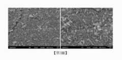
第2圖至第5圖為1 wt% ZnO-TiO2奈米纖維、3 wt% ZnO-TiO2奈米纖維、5 wt% ZnO-TiO2奈米纖維和Ag-ZnO-TiO2奈米纖維的場發射掃描式電子顯微鏡圖像。結果顯示成功地使用靜電紡絲法製備出線性的一維奈米纖維。此外,再使用軟體Image J分析第2圖至第5圖中奈米纖維的直徑。1 wt% ZnO-TiO2奈米纖維的直徑為0.177 ± 0.029微米。3 wt% ZnO-TiO2奈米纖維的直徑為0.142 ± 0.012微米。5 wt% ZnO-TiO2奈米纖維的直徑為0.125 ± 0.017微米。Ag-ZnO-TiO2奈米纖維的直徑為0.150 ± 0.021微米。第6圖為光陽極中奈米纖維層和TiO2層的橫截面的發射掃描式電子顯微鏡圖像。旋轉塗佈法製成的TiO2層厚度為2.72微米,刮刀法製成的TiO2層厚度為19.98微米,奈米纖維的厚度為6.20微米。Figures 2 to 5 are field emission scans of 1 wt% ZnO-TiO2 nanofibers, 3 wt% ZnO-TiO2 nanofibers, 5 wt% ZnO-TiO2 nanofibers and Ag-ZnO-TiO2 nanofibers electron microscope image. The results showed that linear one-dimensional nanofibers were successfully prepared by electrospinning. In addition, the software Image J was used to analyze the diameters of nanofibers in Figures 2 to 5. The diameter of 1 wt% ZnO-TiO2 nanofibers is 0.177 ± 0.029 μm. The diameter of 3 wt% ZnO-TiO2 nanofibers is 0.142 ± 0.012 μm. The diameter of 5 wt% ZnO-TiO2 nanofibers is 0.125 ± 0.017 μm. The diameter of Ag-ZnO-TiO2 nanofibers is 0.150 ± 0.021 microns. Figure 6 is an emission scanning electron microscope image of a cross-section of the nanofiber layer and the TiO2 layer in the photoanode. The thickness of the TiO2 layer made by the spin coating method is 2.72 microns, the thickness of the TiO2 layer made by the doctor blade method is 19.98 microns, and the thickness of the nanofibers is 6.20 microns.
實施例4-能量發散光譜儀分析Embodiment 4-energy dispersive spectrometer analysis
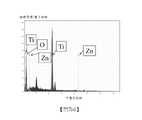
第7圖至第10圖為1 wt% ZnO-TiO2奈米纖維、3 wt% ZnO-TiO2奈米纖維、5 wt% ZnO-TiO2奈米纖維和Ag-ZnO-TiO2奈米纖維的能量發散光譜儀分析圖。其中X軸為相對強度/電子伏特,Y軸為千電子伏特。第7圖1 wt% ZnO-TiO2奈米纖維由46.96重量百分比的鈦、0.90重量百分比的鋅及52.14重量百分比的氧所組成,證實了奈米纖維中鈦、鋅及氧的存在。第8圖3 wt% ZnO-TiO2奈米纖維由49.66重量百分比的鈦、2.46重量百分比的鋅及47.87重量百分比的氧所組成,證實了奈米纖維中鈦、鋅及氧的存在。第9圖5 wt% ZnO-TiO2奈米纖維由47.24重量百分比的鈦、3.53重量百分比的鋅及49.23重量百分比的氧所組成,證實了奈米纖維中鈦、鋅及氧的存在。第10圖Ag- ZnO-TiO2奈米纖維由57.60重量百分比的鈦、3.72重量百分比的鋅、35.74重量百分比的氧及2.94重量百分比的銀所組成,證實了奈米纖維中鈦、鋅、氧及銀的存在。Figures 7 to 10 are energy dispersive spectrometers of 1 wt% ZnO-TiO2 nanofibers, 3 wt% ZnO-TiO2 nanofibers, 5 wt% ZnO-TiO2 nanofibers and Ag-ZnO-TiO2 nanofibers Analysis chart. Where the X-axis is relative intensity/electron volts, and the Y-axis is kiloelectron volts. Figure 7. 1 wt% ZnO-TiO2 nanofibers are composed of 46.96 weight percent titanium, 0.90 weight percent zinc and 52.14 weight percent oxygen, confirming the presence of titanium, zinc and oxygen in the nanofibers. Figure 8. 3 wt% ZnO-TiO2 nanofibers are composed of 49.66 wt% titanium, 2.46 wt% zinc and 47.87 wt% oxygen, confirming the presence of titanium, zinc and oxygen in the nanofibers. Figure 9. 5 wt% ZnO-TiO2 nanofibers are composed of 47.24 wt% titanium, 3.53 wt% zinc and 49.23 wt% oxygen, confirming the presence of titanium, zinc and oxygen in the nanofibers. Figure 10 Ag-ZnO-TiO2 nanofibers are composed of 57.60% by weight of titanium, 3.72% by weight of zinc, 35.74% by weight of oxygen and 2.94% by weight of silver, confirming that titanium, zinc, oxygen and the presence of silver.
實施例5- ZnO-TiO2奈米纖維X光繞射分析Example 5-ZnO-TiO2 Nanofiber X-ray Diffraction Analysis
第11圖至第13圖為1 wt% ZnO-TiO2奈米纖維、3 wt% ZnO-TiO2奈米纖維和5 wt% ZnO-TiO2奈米纖維的X光繞射儀分析圖譜。其中X軸為2-Theta角,Y軸為峰值強度。結果表明,三種ZnO-TiO2奈米纖維均表現出TiO2銳鈦礦和TiO2金紅石的衍射峰。ZnO-TiO2奈米纖維中出現的TiO2銳鈦礦的衍射峰為2θ= 25.12°(101)、37.25°(103)、37.56°(004)、38.53°(112)、47.92 °(200)、53.91°(105)、54.38°(211)、62.63°(2 1 3)、68.74°(220)。ZnO-TiO2奈米纖維中出現的TiO2金紅石的衍射峰為2θ= 27.36°(110)、35.92°(101)、41.01°(200)。ZnO-TiO2奈米纖維中ZnO的衍射峰相對較弱。ZnO-TiO2奈米纖維中出現的ZnO樣品的衍射峰為2θ= 31.48°(100)、34.46°(002)、36.09°(101)、56.42°(110)、62.81°(103)、66.14°(200)、67.65°(112)、69.12°(201)。由於ZnO的含量低,因此ZnO的衍射峰不明顯。發現隨著ZnO的重量百分比增加,TiO2的衍射峰強度逐漸降低。Figures 11 to 13 are X-ray diffraction analysis spectra of 1 wt% ZnO-TiO2 nanofibers, 3 wt% ZnO-TiO2 nanofibers and 5 wt% ZnO-TiO2 nanofibers. where the X-axis is the 2-Theta angle and the Y-axis is the peak intensity. The results show that the three ZnO-TiO2 nanofibers all exhibit the diffraction peaks of TiO2 anatase and TiO2 rutile. The diffraction peaks of TiO2 anatase in ZnO-TiO2 nanofibers are 2θ= 25.12° (101), 37.25° (103), 37.56° (004), 38.53° (112), 47.92° (200), 53.91 ° (105), 54.38° (211), 62.63° (2 1 3), 68.74° (220). The diffraction peaks of TiO2 rutile in ZnO-TiO2 nanofibers are 2θ = 27.36° (110), 35.92° (101), 41.01° (200). The diffraction peaks of ZnO in ZnO-TiO2 nanofibers are relatively weak. The diffraction peaks of ZnO samples appearing in ZnO-TiO2 nanofibers are 2θ= 31.48° (100), 34.46° (002), 36.09° (101), 56.42° (110), 62.81° (103), 66.14° ( 200), 67.65° (112), 69.12° (201). Due to the low content of ZnO, the diffraction peaks of ZnO are not obvious. It was found that the intensity of the diffraction peaks of TiO2 decreased gradually with the weight percentage of ZnO increasing.
實施例6- Ag-ZnO-TiO2奈米纖維X光繞射分析Example 6-Ag-ZnO-TiO2 nanofiber X-ray diffraction analysis
第14圖為Ag-ZnO-TiO2奈米纖維的X光繞射儀分析圖譜。其中X軸為2-Theta角,Y軸為峰值強度。結果表明,Ag-ZnO-TiO2奈米纖維表現出TiO2銳鈦礦、TiO2金紅石、ZnO和Ag的衍射峰。Ag-ZnO-TiO2奈米纖維中TiO2銳鈦礦、TiO2金紅石、ZnO樣品的衍射峰位置與ZnO-TiO2奈米纖維相似。Ag-ZnO-TiO2奈米纖維中出現的TiO2銳鈦礦的衍射峰為2θ= 25.13°(101)、37.33°(103)、37.73°(004)、38.44°(112)、47.96°(200)、53.94°(105)、54.88°(211),62.68°(213),68.82°(220)。Ag-ZnO-TiO2奈米纖維中出現的TiO2金紅石的衍射峰為2θ= 27.35°(110)、36.01°(101)、41.12°(200)。Ag-ZnO-TiO2奈米纖維中出現的ZnO樣品的衍射峰為2θ= 30.65°(100)、34.60°(002)、36.71°(101)、56.55°(110)、62.76°(103)、66.53°(200)、67.48°(112)、69.22°(201)。Ag-ZnO-TiO2奈米纖維中出現的Ag的衍射峰為2θ= 37.90°(111)、44.67°(200)。Ag-ZnO-TiO2奈米纖維中ZnO樣品和Ag樣品的衍射峰均較弱。Figure 14 is the X-ray diffraction analysis spectrum of Ag-ZnO-TiO2 nanofibers. where the X-axis is the 2-Theta angle and the Y-axis is the peak intensity. The results show that the Ag-ZnO-TiO2 nanofibers exhibit the diffraction peaks of TiO2 anatase, TiO2 rutile, ZnO and Ag. The diffraction peak positions of TiO2 anatase, TiO2 rutile and ZnO samples in Ag-ZnO-TiO2 nanofibers are similar to those of ZnO-TiO2 nanofibers. The diffraction peaks of TiO2 anatase in Ag-ZnO-TiO2 nanofibers are 2θ= 25.13° (101), 37.33° (103), 37.73° (004), 38.44° (112), 47.96° (200) , 53.94° (105), 54.88° (211), 62.68° (213), 68.82° (220). The diffraction peaks of TiO2 rutile in Ag-ZnO-TiO2 nanofibers are 2θ = 27.35° (110), 36.01° (101), 41.12° (200). The diffraction peaks of ZnO samples appearing in Ag-ZnO-TiO2 nanofibers are 2θ= 30.65°(100), 34.60°(002), 36.71°(101), 56.55°(110), 62.76°(103), 66.53 °(200), 67.48°(112), 69.22°(201). The diffraction peaks of Ag appearing in Ag-ZnO-TiO2 nanofibers are 2θ= 37.90° (111), 44.67° (200). The diffraction peaks of ZnO samples and Ag samples in Ag-ZnO-TiO2 nanofibers are weak.
實施例7-染料敏化太陽能電池的短路電流密度-開路電壓測試Example 7-Short-circuit current density-open-circuit voltage test of dye-sensitized solar cells
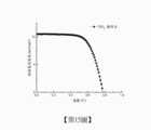
第15圖為TiO2標準品染料敏化太陽能電池的短路電流密度-開路電壓曲線。通過旋轉塗佈法和刮刀法製成的純TiO2基光電陽極作為實驗標準品。其中X軸為電壓,Y軸為短路電流密度。光伏參數如短路電流密度(JSC),開路電壓(VOC),填充因子(F.F.)和功率轉換效率(η)分別顯示在表1中。在表1中,TiO2標準品染料敏化太陽能電池的短路電流密度(JSC)為10.74 mA/cm2,開路電壓(VOC)為0.78 V,填充因子(F.F.)為0.66,功率轉換效率(η)為5.44%。Fig. 15 is the short circuit current density-open circuit voltage curve of TiO2 standard dye-sensitized solar cell. Pure TiO2-based photoanodes fabricated by spin-coating and doctor blade methods were used as experimental standards. The X-axis is the voltage, and the Y-axis is the short-circuit current density. The photovoltaic parameters such as short-circuit current density (JSC), open-circuit voltage (VOC), fill factor (F.F.) and power conversion efficiency (η) are shown in Table 1, respectively. In Table 1, the short-circuit current density (JSC) of TiO2 standard dye-sensitized solar cells is 10.74 mA/cm2, the open-circuit voltage (VOC) is 0.78 V, the fill factor (F.F.) is 0.66, and the power conversion efficiency (η) is 5.44%.
表1:TiO2標準品染料敏化太陽能電池的光伏參數。
第16圖不同重量比ZnO-TiO2奈米纖維修飾光陽極的染料敏化太陽能電池的短路電流密度-開路電壓曲線。其中X軸為電壓,Y軸為短路電流密度。光伏參數如短路電流密度(JSC),開路電壓(VOC),填充因子(F.F.)和功率轉換效率(η)分別顯示在表2中。光伏效率中存在最適當的ZnO摻雜濃度。如表2所示,用3 wt% ZnO-TiO2奈米纖維修飾的染料敏化太陽能電池有最高功率轉換效率(η)為6.28%,與未經修飾的光陽極(TiO2標準品)相比,提高了15.44%。其他光伏參數,例如短路電流密度(JSC)、開路電壓(VOC)和填充因子(F.F.)。分別為12.18 mA/cm2、0.77 V和0.67。由於ZnO的摻入,電流密度的增加可歸因於快速的電子傳輸。Figure 16 shows the short-circuit current density-open-circuit voltage curves of dye-sensitized solar cells with different weight ratios of ZnO-TiO2 nanofibers modified photoanodes. The X-axis is the voltage, and the Y-axis is the short-circuit current density. Photovoltaic parameters such as short-circuit current density (JSC), open-circuit voltage (VOC), fill factor (F.F.) and power conversion efficiency (η) are shown in Table 2, respectively. There is an optimum ZnO doping concentration in photovoltaic efficiency. As shown in Table 2, the dye-sensitized solar cells decorated with 3 wt% ZnO-TiO2 nanofibers had the highest power conversion efficiency (η) of 6.28%, compared with the unmodified photoanode (TiO2 standard), An increase of 15.44%. Other photovoltaic parameters such as short circuit current density (JSC), open circuit voltage (VOC) and fill factor (F.F.). They are 12.18 mA/cm2, 0.77 V and 0.67, respectively. The increase in current density can be attributed to the fast electron transport due to the incorporation of ZnO.
表2:不同重量比ZnO-TiO2奈米纖維修飾光陽極的染料敏化太陽能電池的的光伏參數。
第17圖為Ag-ZnO-TiO2奈米纖維修飾光陽極的染料敏化太陽能電池的短路電流密度-開路電壓曲線。其中X軸為電壓,Y軸為短路電流密度。根據不同重量比的ZnO-TiO2奈米纖維修飾的光陽極的染料敏化太陽能電池的實驗結果,我們選擇了具有最佳光伏參數的3 wt% ZnO-TiO2奈米纖維修飾的光陽極的染料敏化太陽能電池作為Ag-ZnO-TiO2奈米纖維的基礎,並添加了32mg AgNO3作為銀的來源。在表3中,Ag-ZnO-TiO2奈米纖維修飾的染料敏化太陽能電池的短路電流密度(JSC)為12.78 mA/cm2,開路電壓(VOC)為0.76 V,填充因子(F.F.)為0.66,功率轉換效率(η)為6.43%。Ag的添加改善了染料敏化太陽能電池中電子的傳輸。Figure 17 is the short-circuit current density-open-circuit voltage curve of the dye-sensitized solar cell with Ag-ZnO-TiO2 nanofiber modified photoanode. The X-axis is the voltage, and the Y-axis is the short-circuit current density. According to the experimental results of dye-sensitized solar cells with different weight ratios of ZnO-TiO2 nanofiber-modified photoanodes, we selected 3 wt% ZnO-TiO2 nanofiber-modified photoanodes with the best photovoltaic parameters for dye-sensitized solar cells. The solar cell was used as the basis of Ag-ZnO-TiO2 nanofibers, and 32mg AgNO3 was added as a source of silver. In Table 3, the short-circuit current density (JSC) of the Ag-ZnO-TiO2 nanofiber modified dye-sensitized solar cell is 12.78 mA/cm2, the open-circuit voltage (VOC) is 0.76 V, and the fill factor (F.F.) is 0.66, The power conversion efficiency (η) is 6.43%. The addition of Ag improves the transport of electrons in dye-sensitized solar cells.
表3:Ag-ZnO-TiO2奈米纖維修飾光陽極的染料敏化太陽能電池的的光伏參數。
第18圖為ZnO-TiO2奈米纖維、Ag-ZnO-TiO2奈米纖維修飾與未經修飾的光陽極的染料敏化太陽能電池的入射光子轉換成電子的轉換效率分析圖。其中X軸為外部量子效率,Y軸為波長。為了進一步觀察染料敏化太陽能電池從入射光子到光譜不同波長電流的轉換效率的變化,可以進行入射光子到電流轉換效率(IPCE)的測量。在三個重量比的ZnO/TiO2中,可選擇表現出最佳的功率轉換效率的3 wt% ZnO-TiO2奈米纖維修飾的染料敏化太陽能電池作為ZnO/TiO2奈米纖維修飾的染料敏化太陽能電池的代表。根據本實施例,係測試了用3 wt% ZnO-TiO2奈米纖維修飾的染料敏化太陽能電池,用Ag-ZnO-TiO2奈米纖維修的染料敏化太陽能電池、和未改性奈米纖維的TiO2標準品的染料敏化太陽能電池的入射光子轉換到電子的轉換效率。從結果可看出,3 wt% ZnO-TiO2奈米纖維修飾的染料敏化太陽能電池在400nm至800nm處顯示出比TiO2標準品的染料敏化太陽能電池更高的外部量子效率。用Ag-ZnO-TiO2奈米纖維修的染料敏化太陽能電池在400nm至800nm處也比用3 wt% ZnO-TiO2奈米纖維修飾的染料敏化太陽能電池表現出更高的外部量子效率。因此,顯示添加ZnO和Ag可以提高DSSC的外部量子效率。IPCE是染料的光吸收效率(ηabs),電子注入的量子產率(ηinj)和在導電玻璃基板上收集注入的電子的效率(ηcol)的乘積。不限於任何理論,ηcol得以改善的原因可能起因於由於添加ZnO和Ag引起的快速電子傳輸和降低的電子復合,因而改善了ηcol並導致IPCE上升。此外,光伏測量結果中JSC的上升趨勢也與IPCE結果一致。Figure 18 is an analysis diagram of the conversion efficiency of incident photons into electrons in dye-sensitized solar cells with ZnO-TiO2 nanofibers, Ag-ZnO-TiO2 nanofibers modified and unmodified photoanodes. Where the X-axis is the external quantum efficiency, and the Y-axis is the wavelength. In order to further observe the change of conversion efficiency of dye-sensitized solar cells from incident photons to current at different wavelengths of the spectrum, the measurement of incident photon-to-current conversion efficiency (IPCE) can be performed. Among the three weight ratios of ZnO/TiO2, 3 wt% ZnO-TiO2 nanofiber-modified dye-sensitized solar cells that exhibit the best power conversion efficiency can be selected as ZnO/TiO2 nanofiber-modified dye-sensitized solar cells Representation of solar cells. According to this example, a dye-sensitized solar cell modified with 3 wt% ZnO-TiO2 nanofibers, a dye-sensitized solar cell modified with Ag-ZnO-TiO2 nanofibers, and unmodified nanofibers were tested. Conversion efficiency of incident photons to electrons in dye-sensitized solar cells of TiO2 standards. From the results, it can be seen that the 3 wt% ZnO-TiO2 nanofiber modified DSCs showed higher external quantum efficiencies at 400 nm to 800 nm than those of TiO2 standard. The dye-sensitized solar cells modified with Ag-ZnO-TiO2 nanofibers also showed higher external quantum efficiency at 400 nm to 800 nm than those modified with 3 wt% ZnO-TiO2 nanofibers. Therefore, it is shown that the addition of ZnO and Ag can enhance the external quantum efficiency of DSSCs. IPCE is the product of the light absorption efficiency of the dye (ηabs), the quantum yield of electron injection (ηinj), and the efficiency of collecting the injected electrons (ηcol) on the conductive glass substrate. Without being limited to any theory, the reason for the improvement in ηcol may arise from the fast electron transport and reduced electron recombination due to the addition of ZnO and Ag, thus improving ηcol and leading to an increase in IPCE. In addition, the rising trend of JSC in the photovoltaic measurements is also consistent with the IPCE results.
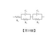
第19圖為染料敏化太陽能電池的等效電路圖。Fig. 19 is an equivalent circuit diagram of a dye-sensitized solar cell.
第20圖TiO2標準品、各種重量比的ZnO-TiO2奈米纖維修飾的染料敏化太陽能電池和Ag-ZnO-TiO2奈米纖維修飾的染料敏化太陽能電池的奈奎斯特圖。其中X軸為實部阻抗,Y軸為虛部阻抗。阻抗值總結在表4中。奈奎斯特圖中有兩個半圓形。R1是對電極/電解質界面上電子轉移的電阻。R2是在光陽極/電解質界面的電子轉移電阻。RS是FTO玻璃和電線之間的阻抗。由於只修改了DSSC中的光電陽極,因此不會影響RS的值。但是,當夾具的位置改變時,可能會改變RS的值。在奈奎斯特曲線中,當R2的半徑越大,電子復合電阻越大。在各種重量比的ZnO-TiO2奈米纖維修飾的染料敏化太陽能電池中,3 wt% ZnO-TiO2奈米纖維修飾的光陽極具有最大半徑和最大電子復合阻抗。據推測,但不限於任何理論,ZnO的摻入可以使電子快速傳輸並減少電子復合的機會。另外,與3 wt% ZnO-TiO2奈米纖維修飾的光陽極相比,Ag-ZnO-TiO2奈米纖維修飾的光陽極具有更大的R2半徑。因此,Ag的摻入進一步降低了電子復合的機會。Figure 20. Nyquist plots of TiO2 standard, various weight ratios of ZnO-TiO2 nanofibers modified dye-sensitized solar cells and Ag-ZnO-TiO2 nanofibers modified dye-sensitized solar cells. Among them, the X-axis is the real part impedance, and the Y-axis is the imaginary part impedance. Impedance values are summarized in Table 4. There are two semicircles in the Nyquist diagram. R1 is the resistance to electron transfer at the electrode/electrolyte interface. R2 is the electron transfer resistance at the photoanode/electrolyte interface. RS is the impedance between the FTO glass and the wire. Since only the photoanode in the DSSC is modified, it does not affect the value of RS. However, when the position of the fixture is changed, the value of RS may be changed. In the Nyquist curve, when the radius of R2 is larger, the electron recombination resistance is larger. Among ZnO-TiO2 nanofiber-modified dye-sensitized solar cells with various weight ratios, the 3 wt% ZnO-TiO2 nanofiber-modified photoanode has the largest radius and the largest electron recombination resistance. It is speculated, but not limited to any theory, that the incorporation of ZnO can enable fast electron transport and reduce the chance of electron recombination. In addition, the Ag-ZnO-TiO2 nanofiber-modified photoanode has a larger R2 radius compared with the 3 wt% ZnO-TiO2 nanofiber-modified photoanode. Therefore, the incorporation of Ag further reduces the chance of electron recombination.
表4:TiO2標準品、各種重量比的ZnO-TiO2奈米纖維修飾的染料敏化太陽能電池和Ag-ZnO-TiO2奈米纖維修飾的染料敏化太陽能電池的電化學阻抗譜分析的阻抗值結果。
10:染料敏化太陽能電池 20:外部負載 30:外部光源 102:第一導電基板 104:第一半導體多孔層 106:第二半導體多孔層 108:染料 110:電解質 112:催化層 114:第二導電基板10: Dye-sensitized solar cells 20: External load 30: External light source 102: the first conductive substrate 104: the first semiconductor porous layer 106: second semiconductor porous layer 108: Dye 110: Electrolyte 112: catalytic layer 114: the second conductive substrate
為使本發明之研究方法、材料分析及測量結果更加前顯易懂,下文列舉出較佳實施例,並配合圖式做詳細說明,如下所式: 第1圖係顯示複合奈米纖維之染料敏化太陽能電池之剖面示意圖。 第2圖係顯示1 wt% ZnO-TiO2奈米纖維的場發射掃描式電子顯微鏡圖像(a放大5000倍,b放大10000倍)。 第3圖係顯示3 wt% ZnO-TiO2奈米纖維的場發射掃描式電子顯微鏡圖像(a放大5000倍,b放大10000倍)。 第4圖係顯示5 wt% ZnO-TiO2奈米纖維的場發射掃描式電子顯微鏡圖像(a放大5000倍,b放大10000倍)。 第5圖係顯示Ag-ZnO-TiO2奈米纖維的場發射掃描式電子顯微鏡圖像(a放大5000倍,b放大10000倍)。 第6圖係顯示光陽極中奈米纖維層和TiO2層的橫截面的發射掃描式電子顯微鏡圖像。 第7圖係顯示1 wt% ZnO-TiO2奈米纖維的能量發散光譜儀分析圖。 第8圖係顯示3 wt% ZnO-TiO2奈米纖維的能量發散光譜儀分析圖。 第9圖係顯示5 wt% ZnO-TiO2奈米纖維的能量發散光譜儀分析圖。 第10圖係顯示Ag-ZnO-TiO2奈米纖維的能量發散光譜儀分析圖。 第11圖係顯示1 wt% ZnO-TiO2奈米纖維的X光繞射儀分析圖譜。 第12圖係顯示3 wt% ZnO-TiO2奈米纖維的X光繞射儀分析圖譜。 第13圖係顯示5 wt% ZnO-TiO2奈米纖維的X光繞射儀分析圖譜。 第14圖係顯示Ag-ZnO-TiO2奈米纖維的X光繞射儀分析圖譜。 第15圖係顯示TiO2標準品染料敏化太陽能電池的短路電流密度-開路電壓曲線。 第16圖係顯示不同重量比ZnO-TiO2奈米纖維修飾光陽極的染料敏化太陽能電池的短路電流密度-開路電壓曲線。 第17圖係顯示Ag-ZnO-TiO2奈米纖維修飾光陽極的染料敏化太陽能電池的短路電流密度-開路電壓曲線。 第18圖係顯示ZnO-TiO2奈米纖維、Ag-ZnO-TiO2奈米纖維修飾與未經修飾的光陽極的染料敏化太陽能電池的入射光子轉換成電子的轉換效率分析圖。 第19圖係顯示染料敏化太陽能電池的等效電路圖。 第20圖係顯示顯示TiO2標準品、各種重量比的ZnO-TiO2奈米纖維修飾的染料敏化太陽能電池和Ag-ZnO-TiO2奈米纖維修飾的染料敏化太陽能電池的奈奎斯特圖。In order to make the research method, material analysis and measurement results of the present invention more obvious and easy to understand, the preferred embodiments are listed below, and are described in detail in conjunction with the drawings, as follows: Figure 1 is a schematic cross-sectional view of a dye-sensitized solar cell showing composite nanofibers. Figure 2 shows a field emission scanning electron microscope image of 1 wt% ZnO-TiO2 nanofibers (a 5000 times magnification, b 10000 times magnification). Figure 3 shows the field emission scanning electron microscope image of 3 wt% ZnO-TiO2 nanofibers (a 5000 times magnification, b 10000 times magnification). Figure 4 shows the field emission scanning electron microscope image of 5 wt% ZnO-TiO2 nanofibers (a magnification 5000 times, b magnification 10000 times). Figure 5 shows the field emission scanning electron microscope image of Ag-ZnO-TiO2 nanofibers (a magnification 5000 times, b magnification 10000 times). Figure 6 is an emission scanning electron microscope image showing the cross-section of the nanofiber layer and the TiO2 layer in the photoanode. Figure 7 shows the energy dispersive spectrometer analysis graph of 1 wt% ZnO-TiO2 nanofibers. Figure 8 shows the energy dispersive spectrometer analysis graph of 3 wt% ZnO-TiO2 nanofibers. Figure 9 shows the energy dispersive spectrometer analysis graph of 5 wt% ZnO-TiO2 nanofibers. Fig. 10 is an energy dispersive spectrometer analysis graph showing Ag-ZnO-TiO2 nanofibers. Figure 11 shows the X-ray diffractometer analysis spectrum of 1 wt% ZnO-TiO2 nanofibers. Figure 12 shows the X-ray diffractometer analysis spectrum of 3 wt% ZnO-TiO2 nanofibers. Figure 13 shows the X-ray diffractometer analysis spectrum of 5 wt% ZnO-TiO2 nanofibers. Figure 14 shows the X-ray diffraction analysis spectrum of Ag-ZnO-TiO2 nanofibers. Fig. 15 shows the short-circuit current density-open-circuit voltage curve of TiO2 standard dye-sensitized solar cells. Figure 16 shows the short-circuit current density-open-circuit voltage curves of dye-sensitized solar cells with different weight ratios of ZnO-TiO2 nanofibers modified photoanodes. Fig. 17 shows the short-circuit current density-open-circuit voltage curve of the dye-sensitized solar cell with Ag-ZnO-TiO2 nanofiber modified photoanode. Fig. 18 is an analysis graph showing the conversion efficiency of incident photons into electrons in dye-sensitized solar cells with ZnO-TiO2 nanofibers, Ag-ZnO-TiO2 nanofibers modified and unmodified photoanodes. FIG. 19 shows an equivalent circuit diagram of a dye-sensitized solar cell. Figure 20 shows Nyquist plots showing TiO2 standard, various weight ratios of ZnO-TiO2 nanofiber-modified dye-sensitized solar cells, and Ag-ZnO-TiO2 nanofiber-modified dye-sensitized solar cells.
10:染料敏化太陽能電池10: Dye-sensitized solar cells
20:外部負載20: External load
30:外部光源30: External light source
102:第一導電基板102: the first conductive substrate
104:第一半導體多孔層104: the first semiconductor porous layer
106:第二半導體多孔層106: second semiconductor porous layer
108:染料108: Dye
110:電解質110: Electrolyte
112:催化層112: catalytic layer
114:第二導電基板114: the second conductive substrate
Claims (10)
Translated fromChinesePriority Applications (1)
| Application Number | Priority Date | Filing Date | Title |
|---|---|---|---|
| TW110109311ATWI794772B (en) | 2021-03-16 | 2021-03-16 | Dye-sensitized solar cell modified by nanofibers |
Applications Claiming Priority (1)
| Application Number | Priority Date | Filing Date | Title |
|---|---|---|---|
| TW110109311ATWI794772B (en) | 2021-03-16 | 2021-03-16 | Dye-sensitized solar cell modified by nanofibers |
Publications (2)
| Publication Number | Publication Date |
|---|---|
| TW202237919A TW202237919A (en) | 2022-10-01 |
| TWI794772Btrue TWI794772B (en) | 2023-03-01 |
Family
ID=85460291
Family Applications (1)
| Application Number | Title | Priority Date | Filing Date |
|---|---|---|---|
| TW110109311ATWI794772B (en) | 2021-03-16 | 2021-03-16 | Dye-sensitized solar cell modified by nanofibers |
Country Status (1)
| Country | Link |
|---|---|
| TW (1) | TWI794772B (en) |
Citations (3)
| Publication number | Priority date | Publication date | Assignee | Title |
|---|---|---|---|---|
| WO2009006910A2 (en)* | 2007-07-09 | 2009-01-15 | Tallinn University Of Technology | Photovoltaic cell based on zinc oxide nanorods and method for making the same |
| US20140083481A1 (en)* | 2011-05-09 | 2014-03-27 | 3M Innovative Properties Company | Photovoltaic module |
| TW202021144A (en)* | 2018-11-22 | 2020-06-01 | 國立雲林科技大學 | Dye-sensitized solar cell |
- 2021
- 2021-03-16TWTW110109311Apatent/TWI794772B/enactive
Patent Citations (3)
| Publication number | Priority date | Publication date | Assignee | Title |
|---|---|---|---|---|
| WO2009006910A2 (en)* | 2007-07-09 | 2009-01-15 | Tallinn University Of Technology | Photovoltaic cell based on zinc oxide nanorods and method for making the same |
| US20140083481A1 (en)* | 2011-05-09 | 2014-03-27 | 3M Innovative Properties Company | Photovoltaic module |
| TW202021144A (en)* | 2018-11-22 | 2020-06-01 | 國立雲林科技大學 | Dye-sensitized solar cell |
Also Published As
| Publication number | Publication date |
|---|---|
| TW202237919A (en) | 2022-10-01 |
Similar Documents
| Publication | Publication Date | Title |
|---|---|---|
| JP5389372B2 (en) | Photoelectrode for dye-sensitized solar cell containing hollow spherical metal oxide nanoparticles and method for producing the same | |
| US9368287B2 (en) | Dye-sensitized solar cell with metal oxide layer containing metal oxide nanoparticles produced by electrospinning and method for manufacturing same | |
| Chang et al. | Optimization of dye adsorption time and film thickness for efficient ZnO dye-sensitized solar cells with high at-rest stability | |
| Lee et al. | Preparations of TiO2 pastes and its application to light-scattering layer for dye-sensitized solar cells | |
| US20090211639A1 (en) | dye-sensitized solar cell having nanostructure absorbing multi-wavelength, and a method for preparing the same | |
| Tubtimtae et al. | Ag2S quantum dot-sensitized WO3 photoelectrodes for solar cells | |
| JP2008218394A (en) | Dye-sensitized solar cell and method for producing dye-sensitized solar cell | |
| US20120309126A1 (en) | Method of manufacturing photoelectrode structure | |
| KR101234239B1 (en) | Dye sensitized solar cell, and manufacturing method thereof | |
| Shang et al. | Preparation of hierarchical tin oxide microspheres and their application in dye-sensitized solar cells | |
| Yang et al. | TiO 2 nanoparticle/nanofiber–ZnO photoanode for the enhancement of the efficiency of dye-sensitized solar cells | |
| JP2011236104A (en) | Titanium oxide structure and method for producing the same, and photoelectric conversion device using the titanium oxide structure | |
| Khalifa et al. | Comprehensive performance analysis of dye-sensitized solar cells using single layer TiO2 photoanode deposited using screen printing technique | |
| KR101045849B1 (en) | High Efficiency Flexible Dye-Sensitized Solar Cell and Manufacturing Method Thereof | |
| Hirbodi et al. | Enhanced efficiency, electron lifetime, and eco-friendliness of dye-sensitized solar cells using nanofibrous TiO2/ZnO composite photoanodes and natural anthocyanin sensitizer | |
| JP3740331B2 (en) | Photoelectric conversion device and manufacturing method thereof | |
| Hafez et al. | Highly porous Ba3Ti4Nb4O21 perovskite nanofibers as photoanodes for quasi-solid state dye-sensitized solar cells | |
| JP4716636B2 (en) | Compound semiconductor | |
| Yang et al. | Improved the performance of dye-sensitized solar cells by incorporating mesoporous silica (SBA-15) materials in scattering layer | |
| Liu et al. | Improvement of light harvesting and device performance of dye-sensitized solar cells using rod-like nanocrystal TiO2 overlay coating on TiO2 nanoparticle working electrode | |
| Wang et al. | Facile synthesis of a multifunctional SnO2 nanoparticles/nanosheets composite for dye-sensitized solar cells | |
| Salam et al. | Influence of Al 2 O 3 nanoparticles embedded-TiO 2 nanofibers based photoanodes on photovoltaic performance of a dye sensitized solar cell | |
| KR100846156B1 (en) | Manufacturing method of working electrode using carbon particles and dye-sensitized solar cell module using the same | |
| TWI794772B (en) | Dye-sensitized solar cell modified by nanofibers | |
| Nien et al. | Photoanode Modified by PbTiO 3 or PbTiO 3/TiO 2 Nanofibers in Dye-Sensitized Solar Cell |