TWI790783B - Encoded substrate, coordinate-positioning system and method thereof - Google Patents
Encoded substrate, coordinate-positioning system and method thereofDownload PDFInfo
- Publication number
- TWI790783B TWI790783BTW110138902ATW110138902ATWI790783BTW I790783 BTWI790783 BTW I790783BTW 110138902 ATW110138902 ATW 110138902ATW 110138902 ATW110138902 ATW 110138902ATW I790783 BTWI790783 BTW I790783B
- Authority
- TW
- Taiwan
- Prior art keywords
- grids
- dimension
- coordinate
- pattern
- grid
- Prior art date
Links
Images


Classifications
- G—PHYSICS
- G06—COMPUTING OR CALCULATING; COUNTING
- G06K—GRAPHICAL DATA READING; PRESENTATION OF DATA; RECORD CARRIERS; HANDLING RECORD CARRIERS
- G06K7/00—Methods or arrangements for sensing record carriers, e.g. for reading patterns
- G06K7/10—Methods or arrangements for sensing record carriers, e.g. for reading patterns by electromagnetic radiation, e.g. optical sensing; by corpuscular radiation
- G06K7/14—Methods or arrangements for sensing record carriers, e.g. for reading patterns by electromagnetic radiation, e.g. optical sensing; by corpuscular radiation using light without selection of wavelength, e.g. sensing reflected white light
- G06K7/1404—Methods for optical code recognition
- G06K7/1408—Methods for optical code recognition the method being specifically adapted for the type of code
- G06K7/1417—2D bar codes
- G—PHYSICS
- G06—COMPUTING OR CALCULATING; COUNTING
- G06T—IMAGE DATA PROCESSING OR GENERATION, IN GENERAL
- G06T7/00—Image analysis
- G06T7/70—Determining position or orientation of objects or cameras
- G06T7/73—Determining position or orientation of objects or cameras using feature-based methods
- G—PHYSICS
- G06—COMPUTING OR CALCULATING; COUNTING
- G06K—GRAPHICAL DATA READING; PRESENTATION OF DATA; RECORD CARRIERS; HANDLING RECORD CARRIERS
- G06K19/00—Record carriers for use with machines and with at least a part designed to carry digital markings
- G06K19/06—Record carriers for use with machines and with at least a part designed to carry digital markings characterised by the kind of the digital marking, e.g. shape, nature, code
- G06K19/06009—Record carriers for use with machines and with at least a part designed to carry digital markings characterised by the kind of the digital marking, e.g. shape, nature, code with optically detectable marking
- G06K19/06037—Record carriers for use with machines and with at least a part designed to carry digital markings characterised by the kind of the digital marking, e.g. shape, nature, code with optically detectable marking multi-dimensional coding
- G—PHYSICS
- G06—COMPUTING OR CALCULATING; COUNTING
- G06K—GRAPHICAL DATA READING; PRESENTATION OF DATA; RECORD CARRIERS; HANDLING RECORD CARRIERS
- G06K19/00—Record carriers for use with machines and with at least a part designed to carry digital markings
- G06K19/06—Record carriers for use with machines and with at least a part designed to carry digital markings characterised by the kind of the digital marking, e.g. shape, nature, code
- G06K19/06009—Record carriers for use with machines and with at least a part designed to carry digital markings characterised by the kind of the digital marking, e.g. shape, nature, code with optically detectable marking
- G06K19/06046—Constructional details
- G06K19/06056—Constructional details the marking comprising a further embedded marking, e.g. a 1D bar code with the black bars containing a smaller sized coding
- G—PHYSICS
- G06—COMPUTING OR CALCULATING; COUNTING
- G06K—GRAPHICAL DATA READING; PRESENTATION OF DATA; RECORD CARRIERS; HANDLING RECORD CARRIERS
- G06K19/00—Record carriers for use with machines and with at least a part designed to carry digital markings
- G06K19/06—Record carriers for use with machines and with at least a part designed to carry digital markings characterised by the kind of the digital marking, e.g. shape, nature, code
- G06K19/06009—Record carriers for use with machines and with at least a part designed to carry digital markings characterised by the kind of the digital marking, e.g. shape, nature, code with optically detectable marking
- G06K19/06046—Constructional details
- G06K19/06093—Constructional details the marking being constructed out of a plurality of similar markings, e.g. a plurality of barcodes randomly oriented on an object
- G—PHYSICS
- G06—COMPUTING OR CALCULATING; COUNTING
- G06K—GRAPHICAL DATA READING; PRESENTATION OF DATA; RECORD CARRIERS; HANDLING RECORD CARRIERS
- G06K7/00—Methods or arrangements for sensing record carriers, e.g. for reading patterns
- G06K7/10—Methods or arrangements for sensing record carriers, e.g. for reading patterns by electromagnetic radiation, e.g. optical sensing; by corpuscular radiation
- G06K7/14—Methods or arrangements for sensing record carriers, e.g. for reading patterns by electromagnetic radiation, e.g. optical sensing; by corpuscular radiation using light without selection of wavelength, e.g. sensing reflected white light
- G06K7/1404—Methods for optical code recognition
- G06K7/1408—Methods for optical code recognition the method being specifically adapted for the type of code
- G06K7/1426—Multi-level bar codes
- G—PHYSICS
- G06—COMPUTING OR CALCULATING; COUNTING
- G06T—IMAGE DATA PROCESSING OR GENERATION, IN GENERAL
- G06T7/00—Image analysis
- G06T7/10—Segmentation; Edge detection
- G06T7/13—Edge detection
- G—PHYSICS
- G06—COMPUTING OR CALCULATING; COUNTING
- G06V—IMAGE OR VIDEO RECOGNITION OR UNDERSTANDING
- G06V10/00—Arrangements for image or video recognition or understanding
- G06V10/20—Image preprocessing
- G06V10/22—Image preprocessing by selection of a specific region containing or referencing a pattern; Locating or processing of specific regions to guide the detection or recognition
- G06V10/225—Image preprocessing by selection of a specific region containing or referencing a pattern; Locating or processing of specific regions to guide the detection or recognition based on a marking or identifier characterising the area
- G—PHYSICS
- G06—COMPUTING OR CALCULATING; COUNTING
- G06V—IMAGE OR VIDEO RECOGNITION OR UNDERSTANDING
- G06V10/00—Arrangements for image or video recognition or understanding
- G06V10/20—Image preprocessing
- G06V10/24—Aligning, centring, orientation detection or correction of the image
- G06V10/245—Aligning, centring, orientation detection or correction of the image by locating a pattern; Special marks for positioning
- G—PHYSICS
- G06—COMPUTING OR CALCULATING; COUNTING
- G06Q—INFORMATION AND COMMUNICATION TECHNOLOGY [ICT] SPECIALLY ADAPTED FOR ADMINISTRATIVE, COMMERCIAL, FINANCIAL, MANAGERIAL OR SUPERVISORY PURPOSES; SYSTEMS OR METHODS SPECIALLY ADAPTED FOR ADMINISTRATIVE, COMMERCIAL, FINANCIAL, MANAGERIAL OR SUPERVISORY PURPOSES, NOT OTHERWISE PROVIDED FOR
- G06Q10/00—Administration; Management
- G06Q10/08—Logistics, e.g. warehousing, loading or distribution; Inventory or stock management
- G06Q10/087—Inventory or stock management, e.g. order filling, procurement or balancing against orders
- G—PHYSICS
- G06—COMPUTING OR CALCULATING; COUNTING
- G06T—IMAGE DATA PROCESSING OR GENERATION, IN GENERAL
- G06T2207/00—Indexing scheme for image analysis or image enhancement
- G06T2207/30—Subject of image; Context of image processing
- G06T2207/30204—Marker
Landscapes
- Engineering & Computer Science (AREA)
- Physics & Mathematics (AREA)
- General Physics & Mathematics (AREA)
- Theoretical Computer Science (AREA)
- Computer Vision & Pattern Recognition (AREA)
- Multimedia (AREA)
- Health & Medical Sciences (AREA)
- Electromagnetism (AREA)
- General Health & Medical Sciences (AREA)
- Toxicology (AREA)
- Artificial Intelligence (AREA)
- Image Processing (AREA)
- Wire Bonding (AREA)
- Exposure And Positioning Against Photoresist Photosensitive Materials (AREA)
Abstract
Description
Translated fromChinese本發明涉及基於電腦視覺的物體辨識技術,特別是一種編碼基板、座標定位系統及方法。The invention relates to an object recognition technology based on computer vision, in particular to an encoding substrate, a coordinate positioning system and a method.
商品盤點對於實體零售業而言是一個重要議題,據統計,實體零售業耗費在品盤點上的成本在整體營業成本佔有極高的比例。具體而言,現有的盤點方式係透過人力直接對貨架上商品的數量進行檢查,以針對數量不足的品項進行補貨,然而此種補貨方式需花費大量的人力成本和時間成本,導致盤點效率無法提高。為了強化商店的營運管理以及提升生產力及強化服務體驗,有必要找出一種高效率的盤點方式,藉此提高整體的補貨效率,進而節省企業的人事成本。Product inventory is an important issue for the physical retail industry. According to statistics, the cost of product inventory in the physical retail industry accounts for a very high proportion of the overall operating costs. Specifically, the existing stocktaking method is to directly check the quantity of goods on the shelf by manpower, so as to replenish the items with insufficient quantity. However, this replenishment method requires a lot of labor and time costs, resulting in inventory Efficiency cannot be improved. In order to strengthen store operation management, improve productivity and enhance service experience, it is necessary to find an efficient inventory method, so as to improve the overall replenishment efficiency and save the enterprise's personnel costs.
基於電腦視覺的物體辨識技術已被成功地應用在各種領域,此技術的的前提為:攝像裝置拍攝到的物體的尺寸足以支援辨識時所用的演算法。然而在賣場中,為了有效利用空間,商品通常是緊密地被排列於貨架層板上。此時透過攝像裝置拍攝到的影像,僅能辨識出貨架上最前方的商品,而位於貨架內側的商品則因為前方商品遮擋的問題而無法被辨識,因此無法計算出商品的實際數量。Object recognition technology based on computer vision has been successfully applied in various fields. The premise of this technology is that the size of the object captured by the camera device is sufficient to support the algorithm used for recognition. However, in the store, in order to effectively use the space, the commodities are usually closely arranged on the shelves. At this time, the image captured by the camera device can only recognize the products at the front of the shelf, while the products located inside the shelf cannot be recognized due to the occlusion of the products in front, so the actual quantity of the products cannot be calculated.
有鑑於此,本發明提出一種編碼基板,座標定位系統及其方法,可依據攝像裝置拍攝貨架得到的影像,計算出未放置商品的空位的座標。In view of this, the present invention proposes a coded substrate, a coordinate positioning system and a method thereof, which can calculate the coordinates of the vacant slots where no commodities are placed according to the images captured by the camera device on the shelves.
本發明適用於將編碼基板佈建於貨架層板上,當攝像裝置拍攝貨架層板的影像時,處理器從影像中的編碼基板找到可辨識的編碼圖案,進一步從多個編碼圖案解碼出空位的座標,從而推算出貨架上的商品數量。The present invention is suitable for distributing coded substrates on the shelves. When the camera device captures images of the shelves, the processor finds identifiable coded patterns from the coded substrates in the images, and further decodes vacancies from multiple coded patterns. coordinates, so as to calculate the number of goods on the shelf.
依據本發明一實施例的一種編碼基板,適用於被一攝像裝置拍攝以產生一影像,所述編碼基板包括:排列為二維陣列的多個網格,其中:每一該些網格包含不重疊的一第一圖案及一第二圖案,其中:該第一圖案對應於一第一維度編碼值;該第二圖案對應於一第二維度編碼值;該影像被一處理器執行後掃描該些網格,其中:在一第一維度方向,該處理器依據該些網格中連續排列的至少二者對應的該至少二第一圖案輸出一第一座標;以及在一第二維度方向,該處理器依據該些網格中連續排列的至少二者對應的該至少二第二圖案輸出一第二座標。An encoding substrate according to an embodiment of the present invention is suitable for being photographed by an imaging device to generate an image, the encoding substrate includes: a plurality of grids arranged in a two-dimensional array, wherein: each of the grids includes A first pattern and a second pattern overlapped, wherein: the first pattern corresponds to a first dimension encoding value; the second pattern corresponds to a second dimension encoding value; the image is scanned after being executed by a processor These grids, wherein: in a first dimension direction, the processor outputs a first coordinate according to the at least two first patterns corresponding to at least two consecutively arranged in the grids; and in a second dimension direction, The processor outputs a second coordinate according to the at least two second patterns corresponding to at least two consecutively arranged grids.
依據本發明一實施例的一種座標定位方法,適用於前述之編碼基板,該編碼基板上設置有多個物件,該編碼基板包括排列為二維陣列的多個網格,所述方法包括以一處理器執行下列步驟:控制一攝像裝置拍攝該編碼基板及該些物件產生一影像;在一第一維度方向,從該些網格中找到連續排列的M個網格;在一第二維度方向,從該些網格中找到連續排列的N個網格;依據該M個第一圖案對應的M個第一維度編碼值產生一第一座標;依據該N個第二圖案對應的N個第二維度編碼值產生一第二座標;以及依據該第一座標及該第二座標輸出一定位座標;其中該M個網格對應的該M個第一圖案未被該些物件遮蔽;該N個網格對應的該N個第二圖案未被該些物件遮蔽;且該M個網格中的一者與該N個網格中的一者相同。A coordinate positioning method according to an embodiment of the present invention is applicable to the aforementioned coding substrate, where a plurality of objects are arranged on the coding substrate, and the coding substrate includes a plurality of grids arranged in a two-dimensional array, and the method includes using a The processor executes the following steps: controlling a camera device to photograph the encoding substrate and the objects to generate an image; in a first dimension direction, find M grids arranged continuously from the grids; in a second dimension direction , find N grids arranged continuously from these grids; generate a first coordinate according to the M first dimension coding values corresponding to the M first patterns; The two-dimensional encoding value generates a second coordinate; and outputs a positioning coordinate according to the first coordinate and the second coordinate; wherein the M first patterns corresponding to the M grids are not covered by the objects; the N The N second patterns corresponding to the grids are not covered by the objects; and one of the M grids is the same as one of the N grids.
依據本發明一實施例的座標定位系統,包括前述的編碼基板、攝像裝置及處理器。攝像裝置用於拍攝編碼基板產生影像。處理器電性連接攝像裝置,處理器用於依據影像執行前述的座標定位方法以產生定位座標。A coordinate positioning system according to an embodiment of the present invention includes the aforementioned encoding substrate, a camera device, and a processor. The camera device is used to photograph the coding substrate to generate an image. The processor is electrically connected to the camera device, and the processor is used to execute the aforementioned coordinate positioning method according to the image to generate positioning coordinates.
綜上所述,本發明提出的編碼基板,僅需要在第一維度和第二維度上各找到指定數量的完整網格影像即可進行解碼。本發明提出的網格中的第一圖案及第二圖案簡化了編碼方式,從而讓網格尺寸遠小於傳統的大型編碼圖案。因此,本發明特別適用於貨架層板的空間定位,因為貨架上的商品通常為緊密排列,而傳統的二維條碼由於尺寸較大,無法在狹窄的層板空缺區域中被完整拍攝,因此無法獲得精確的空間定位資訊。反觀本發明提出的編碼基板,其視覺化編碼樣式僅需辨識到貨架層板底部狹長的空缺區域即可進行定位,符合貨架商品陳列之特性。To sum up, the encoding substrate proposed by the present invention only needs to find a specified number of complete grid images in the first dimension and the second dimension respectively for decoding. The first pattern and the second pattern in the grid proposed by the present invention simplify the encoding method, so that the grid size is much smaller than the traditional large-scale encoding pattern. Therefore, the present invention is particularly suitable for the space positioning of the shelves, because the products on the shelves are usually closely arranged, and the traditional two-dimensional barcodes cannot be completely photographed in the narrow space of the shelves due to their large size. Obtain precise spatial positioning information. In contrast to the coded substrate proposed by the present invention, its visual coding style only needs to identify the long and narrow vacant area at the bottom of the shelf layer for positioning, which is in line with the characteristics of shelf product display.
以上之關於本揭露內容之說明及以下之實施方式之說明係用以示範與解釋本發明之精神與原理,並且提供本發明之專利申請範圍更進一步之解釋。The above description of the disclosure and the following description of the implementation are used to demonstrate and explain the spirit and principle of the present invention, and provide a further explanation of the patent application scope of the present invention.
以下在實施方式中詳細敘述本發明之詳細特徵以及特點,其內容足以使任何熟習相關技藝者了解本發明之技術內容並據以實施,且根據本說明書所揭露之內容、申請專利範圍及圖式,任何熟習相關技藝者可輕易地理解本發明相關之構想及特點。以下之實施例係進一步詳細說明本發明之觀點,但非以任何觀點限制本發明之範疇。The detailed features and characteristics of the present invention are described in detail below in the implementation mode, and its content is enough to enable any person familiar with the relevant art to understand the technical content of the present invention and implement it accordingly, and according to the content disclosed in this specification, the scope of the patent application and the drawings , anyone who is familiar with the related art can easily understand the ideas and features related to the present invention. The following examples are to further describe the concept of the present invention in detail, but not to limit the scope of the present invention in any way.
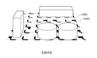
本發明提出一種編碼基板,使用此編碼基板的座標定位系統及其方法,下文先介紹編碼基板的組成,然後說明座標定位系統的其餘裝置以及這些裝置的運作方式。 一般而言,商品在上架時通常是同類商品彼此緊靠,位於最內側的第一列商品靠著貨架背板開始逐列擺設至外側。因此,相對於從物件辨識的角度進行商品辨識,從貨架層板剩餘的空間也可精確推算出商品的數量。有鑑於先前技術僅能辨識出貨架上最前方的商品、而位於貨架內側的商品則因為前方商品遮擋的問題而無法被辨識的問題,本發明著重於從貨架層板剩餘的空間推算商品的數量,可以很好地改善上述缺失。圖1是本發明一實施例的編碼基板的範例,所述編碼基板包括:排列為二維陣列的多個網格,例如圖1展示的編碼基板是由25個網格排列為5×5二維陣列的形式。本發明不限制二維陣列的形狀必須為正方形,對於任意形狀的二維平面結構,只要是採用下文所述的網格組合而成,皆屬於本發明提出的編碼基板的範圍。在實際應用上,考量到貨架的形狀,編碼基板可為非正方形之矩形。The present invention proposes a coded substrate, a coordinate positioning system using the coded substrate and its method. The composition of the coded substrate is firstly introduced below, and then other devices of the coordinate positioning system and their operation modes are explained. Generally speaking, when the products are put on the shelves, the products of the same kind are usually close to each other, and the first row of products located on the innermost side leans against the backboard of the shelf and starts to be arranged row by row to the outside. Therefore, compared to product identification from the perspective of object identification, the quantity of products can also be accurately calculated from the remaining space on the shelves. In view of the problem that the prior art can only identify the products at the front of the shelf, while the products located inside the shelf cannot be identified due to the occlusion of the products in front, the present invention focuses on estimating the value of the products from the remaining space on the shelf. Quantity, can improve the above missing very well. Fig. 1 is an example of a coding substrate according to an embodiment of the present invention, the coding substrate includes: a plurality of grids arranged in a two-dimensional array, for example, the coding substrate shown in Fig. in the form of a dimensional array. The present invention does not limit the shape of the two-dimensional array to be a square. For a two-dimensional planar structure of any shape, as long as it is formed by using the grid described below, it all belongs to the scope of the coding substrate proposed by the present invention. In practical applications, considering the shape of the shelf, the coding substrate may be a non-square rectangle.
圖2是本發明一實施例的網格的範例,每個網格包含不重疊的第一圖案及第二圖案。在此範例中,第一圖案位於網格的左上角,第二圖案位於網格的右下角。從另一角度觀之,每個網格具有一視覺化樣式,此視覺化樣式包含兩個圖案,其中在第一圖案及第二圖案中間必須保留一段空白區域,換言之,此網格必須滿足:至少可找到一條水平掃描線橫越此網格,但不同時通過第一圖案及第二圖案,且至少可找到一條垂直掃描線橫越此網格,但不同時通過第一圖案及第二圖案。透過上述設置,可確保當前網格中的第一圖案及第二圖案彼此不接觸,降低影像辨識上的誤判機率。FIG. 2 is an example of grids according to an embodiment of the present invention, and each grid includes non-overlapping first patterns and second patterns. In this example, the first pattern is in the upper left corner of the grid and the second pattern is in the lower right corner of the grid. From another point of view, each grid has a visual style, and this visual style contains two patterns, and a blank area must be reserved between the first pattern and the second pattern. In other words, the grid must satisfy: At least one horizontal scan line can be found to traverse the grid, but not pass through the first pattern and the second pattern at the same time, and at least one vertical scan line can be found to traverse the grid, but not pass through the first pattern and the second pattern at the same time . Through the above configuration, it can be ensured that the first pattern and the second pattern in the current grid do not touch each other, reducing the probability of misjudgment in image recognition.
在圖2展示的範例中,網格的形狀是正方形,且邊長為d。第一圖案及第二圖案的每一者有兩個邊對齊網格的邊界,其邊長如圖2所標示,然而,圖2中的數值僅為舉例而非用以限制本發明,這些數值可以根據實際設計需求作調整,且網格可以為非正方形之矩形。In the example shown in Figure 2, the shape of the grid is square with side length d. Each of the first pattern and the second pattern has two borders aligned to the grid, the length of which is indicated in Figure 2, however, the numerical values in Figure 2 are for example only and are not intended to limit the present invention, these numerical values It can be adjusted according to actual design requirements, and the grid can be a non-square rectangle.
編碼基板所呈現的二維平面的視覺化樣式,是以二維網格系統(grid system)為基礎進行座標編碼值的分配,其中第一圖案對應於第一維度(如X軸)編碼值,第二圖案對應於第二維度(如Y軸)編碼值。請參考圖3,其繪示編碼值與圖案的對應關係的範例。如圖3所示,八個編碼值0~7分別對應至八個不同樣式的圖案,每個圖案可分為上下兩個部分。請一併參考圖3及圖2的邊長範例,每個部分的像素區塊按邊長可分為三種類型:1×2、4×2、0×0(即空白,無像素填滿),因此,除了上下兩部分皆為0×0類型的像素區塊不適合用來代表編碼值,由兩個像素區塊可以組合出的圖案共有八種(3×3-1)。然而,本發明不限制圖案由幾個部分組成,也不限制每一部分的像素區塊的類型數量,實務上,可根據網格尺寸以及所需編碼的平面尺寸決定上述參數。此外,圖3展示的對應關係適用於第一維度或第二維度。請一併參考圖1及圖3,將圖3中以水平方向(第一維度)展示的對應關係旋轉90度後可得到垂直方向(第二維度)的對應關係。The visual style of the two-dimensional plane presented by the coding substrate is based on the two-dimensional grid system (grid system) for the distribution of coordinate coding values, in which the first pattern corresponds to the coding value of the first dimension (such as the X axis), The second pattern corresponds to encoding values in a second dimension (eg, the Y axis). Please refer to FIG. 3 , which shows an example of the correspondence between encoding values and patterns. As shown in Figure 3, the eight
請再參考圖1所示的編碼基板,在組成編碼基板的多個網格中,若兩個網格共用同一個邊,則稱這兩個網格彼此相鄰。對於所有相鄰的兩個網格,將其中一者稱為第一網格,另一者稱為第二網格;第一網格中的第一圖案與第二網格中的第一圖案不相鄰,且第一網格中的第二圖案與第二網格中的第二圖案不相鄰。上述設置可確保當前網格中的第一圖案及第二圖案分別不與鄰近方格中的第一圖案及一第二圖案接觸,更進一步降低影像辨識上的誤判機率。Please refer to the coding substrate shown in FIG. 1 again. Among the multiple grids forming the coding substrate, if two grids share the same edge, the two grids are said to be adjacent to each other. For all adjacent two grids, one of them is called the first grid, and the other is called the second grid; the first pattern in the first grid and the first pattern in the second grid are not adjacent, and the second pattern in the first grid is not adjacent to the second pattern in the second grid. The above setting can ensure that the first pattern and the second pattern in the current grid do not contact with the first pattern and a second pattern in the adjacent grid respectively, further reducing the probability of misjudgment in image recognition.
本發明一實施例提出的編碼基板適用於被攝像裝置拍攝以產生影像,處理器掃描此影像中拍到的多個網格。在第一維度方向,處理器依據連續排列的至少二網格對應的至少二個第一圖案輸出第一座標。在第二維度方向,處理器依據連續排列的至少二網格對應的至少二個第二圖案輸出第二座標。圖4是一個大型編碼基板的範例,位於X軸下方的數字為第一維度編碼值,位於Y軸右方的數字為第二維度編碼值。下方表格一呈現的對應關係包括編碼序列、取自此序列的連續四個編碼值、以及這四個編碼值代表的座標。表格一的對應關係適用於第一維度及第二維度。The coding substrate proposed by an embodiment of the present invention is suitable for being photographed by a camera device to generate an image, and the processor scans a plurality of grids captured in the image. In the direction of the first dimension, the processor outputs the first coordinates according to at least two first patterns corresponding to at least two grids arranged continuously. In the direction of the second dimension, the processor outputs the second coordinates according to at least two second patterns corresponding to the at least two grids arranged continuously. Figure 4 is an example of a large coded substrate, the numbers below the X-axis are coded values for the first dimension, and the numbers to the right of the Y-axis are coded values for the second dimension. The corresponding relationship presented in Table 1 below includes the coding sequence, four consecutive coding values obtained from this sequence, and the coordinates represented by these four coding values. The corresponding relationship in Table 1 is applicable to the first dimension and the second dimension.
表格一
依據連續四個第一維度編碼值可解碼出第一座標,依據連續四個第二維度編碼值可解碼出第二座標。例如:在圖4標示的L型區域中,連續四個第一維度編碼值為“1 0 2 0”,代表第一座標為10;連續四個第二維度編碼值為“10 0 1”,代表第二座標為4,因此,L型區域的交點的座標為(10, 4)。下文以第一維度編碼值為例,說明產生第一維度編碼值的方式,而產生第二維度編碼值也可遵循相同的方式。The first coordinate can be decoded according to four consecutive coded values of the first dimension, and the second coordinate can be decoded according to four consecutive coded values of the second dimension. For example: in the L-shaped area marked in Figure 4, four consecutive first dimension coding values are "1 0 2 0", which means that the first coordinate is 10; four consecutive second dimension coding values are "10 0 1", It means that the second coordinate is 4, therefore, the coordinate of the intersection point of the L-shaped area is (10, 4). The following takes the first-dimension coded value as an example to illustrate the method of generating the first-dimension coded value, and the same method can be followed to generate the second-dimension coded value.
在第一維度方向,連續排列的多個網格對應於多個第一圖案,而這些第一圖案對應的多個第一維度編碼值係關聯於德布魯因序列(de Bruijn sequence),但本發明不以此為限。德布魯因序列是一個循環序列,記為B(k, n),其定義為:每一個長度為n且由{0, 1, …, k-1}等元素組成的子字串在此序列中只出現一次。例如,B(2, 3)的一個解為序列“00010111”,其中所有長度為3且由{0, 1}等元素組成的子序列為000, 001, 010, 101, 011, 111, 110, 100。In the direction of the first dimension, multiple grids arranged continuously correspond to multiple first patterns, and the multiple coded values of the first dimension corresponding to these first patterns are associated with de Bruijn sequence (de Bruijn sequence), but The present invention is not limited thereto. The De Bruin sequence is a cyclic sequence, denoted as B(k, n), which is defined as: each substring of length n and composed of elements such as {0, 1, ..., k-1} is here Appears only once in the sequence. For example, a solution of B(2, 3) is the sequence "00010111", in which all subsequences of
請參考圖3,從八個編碼值0~7挑選出不重複的兩個編碼值,並滿足第一個挑選的編碼值小於第二個挑選的編碼值,可列舉出28種排列(8×7÷2),包括: “01”, “02”, “03”, …, “07”, “12”, “13”, …, “17”, …, “67”。本發明基於上述排列對B(2, 4)的一個序列 “0000100110101111”進行修改,如下所述:Please refer to Figure 3, select two non-repetitive coded values from eight coded
對於組合“01”,將序列修改為“000010011010 1111”;For combination "01", modify the sequence to "000010011010 1111";
對於組合“02”,將序列修改為“ 000020022020 2222”;…For combination "02", modify the sequence to " 000020022020 2222”;…
對於組合“12”,將序列修改為“111121122121 2222”;…For the combination "12", modify the sequence to "111121122121 2222”;…
對於組合“13”,將序列修改為“ 111131133131 3333”;…For the combination "13", modify the sequence to " 111131133131 3333”;…
對於組合“67”,將序列修改為“ 666676677676 7777”。For the combination "67", modify the sequence to " 666676677676 7777".
在上述修改中,由於“0000”, “1111”, “2222”, …, “7777”等子序列將重複出現,故本發明只保留第一次出現的子序列,並刪除後續重複出現的子序列。按照上述方式,本發明產生一個長度為252字元的編碼序列: “000010011010200220203003303040044040500550506006606070077070111121122121311331314114414151155151611661617117717122223223323242244242522552526226626272277272333343344343533553536336636373377373444454455454644664647447747455556556656575577575666676677676”In the above modification, since subsequences such as "0000", "1111", "2222", ..., "7777" will appear repeatedly, the present invention only retains the subsequence that appears for the first time, and deletes the subsequences that appear repeatedly sequence. In the manner described above, the present invention produces a coded sequence with a length of 252 characters: “000010011010200220203003303040044040500550506006606070077070111121122121311331314114414151155151611661617117717122223223323242244242522552526226626272277272333343344343533553536336636373377373444454455454644664647447747455556556656575577575666676677676”
若一個網格的尺寸為1公分×1公分,則按上述編碼序列構成的編碼基板可支援的尺寸達到6.3504平方公尺(2.52×2.52)。If the size of a grid is 1 cm x 1 cm, the size supported by the coded substrate constructed according to the above coding sequence reaches 6.3504 square meters (2.52 x 2.52).
圖5是本發明一實施例的座標定位方法的流程圖,所述方法適用於圖6A所展示的場景,包括前述的編碼基板以及設置在編碼基板上的多個物件。所述方法包括以處理器執行下列步驟:步驟S1為「控制攝像裝置拍攝編碼基板及物件產生影像」,步驟S2為「在第一維度的方向,找到連續排列的M個網格」,步驟S3為「在第二維度的方向,找到連續排列的N個網格」,步驟S4為「依據M個第一圖案對應的M個第一維度編碼值產生第一座標」,步驟S5為「依據N個第二圖案對應的N個第二維度編碼值產生第二座標」,以及步驟S6為「依據第一座標及第二座標輸出定位座標」。FIG. 5 is a flowchart of a coordinate positioning method according to an embodiment of the present invention. The method is applicable to the scene shown in FIG. 6A , including the aforementioned coding substrate and a plurality of objects disposed on the coding substrate. The method includes executing the following steps with a processor: Step S1 is "controlling the camera device to photograph the encoding substrate and the object to generate an image", step S2 is "finding M grids arranged in a row in the direction of the first dimension", and step S3 is "in the direction of the second dimension, find N grids arranged continuously", step S4 is "generate the first coordinates according to the M first dimension coding values corresponding to the M first patterns", and step S5 is "according to the N The N second-dimension encoding values corresponding to the second patterns generate second coordinates", and step S6 is "outputting positioning coordinates according to the first coordinates and the second coordinates".
在步驟S1中,本發明不限制攝像裝置拍攝編碼基板的角度,例如:當編碼基板設置於賣場貨架的承載板時,盤點人員可以站在貨架前方,使用具有照相功能的智慧型手機拍攝承載板以及乘載板上的商品;也可以在上層的承載板底面設置攝像鏡頭拍攝下層承載板。In step S1, the present invention does not limit the angle at which the camera device captures the coding substrate. For example, when the coding substrate is set on the carrier board of the shelf in the store, the inventory personnel can stand in front of the shelf and use a smartphone with a camera function to take pictures of the carrier board. And take the goods on the loading board; it is also possible to set a camera lens on the bottom surface of the upper loading board to take pictures of the lower loading board.
在步驟S2中,被找到的M個網格必須滿足這M個網格對應的M個第一圖案未被任何物件遮蔽的條件。同理,在步驟S3中,被找到的N個網格必須滿足這N個網格對應的N個第二圖案未被任何物件遮蔽的條件。在本發明一實施例中,M=N=4,然而本發明並不限制M、N的數值大小。In step S2, the found M grids must satisfy the condition that the M first patterns corresponding to the M grids are not covered by any objects. Similarly, in step S3, the found N grids must satisfy the condition that the N second patterns corresponding to the N grids are not covered by any objects. In an embodiment of the present invention, M=N=4, but the present invention does not limit the values of M and N.
步驟S2至S4的流程,基本上與步驟S3至S5的流程一致,其差別在於影像處理時所採用的維度不同。下文以第一維度為例,說明步驟S2至S4的實施細節,步驟S3至步驟S5的流程可依此類推。The flow of steps S2 to S4 is basically the same as the flow of steps S3 to S5, the difference being that the dimensions used in image processing are different. The following takes the first dimension as an example to illustrate the implementation details of steps S2 to S4, and the process of steps S3 to S5 can be deduced in this way.
圖7是圖5中步驟S2的細部流程圖,在第一維度方向從多個網格中找到連續排列的M個網格的方式如下所述:Fig. 7 is a detailed flow chart of step S2 in Fig. 5, and the mode of finding M grids arranged continuously from a plurality of grids in the first dimension direction is as follows:
步驟S21,在第一維度方向,處理器依據影像產生多個候選掃描線SL1~SL3,如圖6A所示。Step S21 , in the first dimension, the processor generates a plurality of candidate scan lines SL1 - SL3 according to the image, as shown in FIG. 6A .
步驟S22,處理器依據這些候選掃描線SL1~SL3及長度閾值決定目標掃描線SL1。長度閾值關聯於解碼出第一座標所需要的第一維度編碼值的數量,在本範例中,長度閾值為4個網格的長度。目標掃描線SL1是候選掃描線SL1~SL3中的至少一者,換言之,處理器在所有水平掃描線SL1~SL3中,找出「通過至少4個網格中間的空白區域」的至少一水平掃描線作為目標掃描線SL1。In step S22, the processor determines the target scan line SL1 according to the candidate scan lines SL1-SL3 and the length threshold. The length threshold is associated with the number of coded values of the first dimension required to decode the first coordinate. In this example, the length threshold is the length of 4 grids. The target scan line SL1 is at least one of the candidate scan lines SL1-SL3. In other words, the processor finds at least one horizontal scan that "passes through the blank area in the middle of at least 4 grids" among all the horizontal scan lines SL1-SL3. line as the target scan line SL1.
步驟S23,處理器依據目標掃描線SL1及邊緣偵測演算法決定網格邊界GM1、GM2,如圖6B所示。詳言之,處理器先依據目標掃描線SL1及指定寬度找到兩個候選區域,然後在這兩個區域中,各自找到符合指定條件的一條網格邊GM1、GM2。所述指定寬度可以是網格的一半邊長,所述的兩個候選區域是從目標掃描線SL1的兩側分別延伸指定寬度所構成,所述指定條件則是與第一圖案重疊比例最高的直線,所述邊緣偵測演算法例如是隨機抽樣一致算法(RANdom SAmple Consensus,RANSAC),此演算法是隨機取樣多個候選點建立直線,再計算該直線與第一圖案的重疊比例。Step S23 , the processor determines the grid boundaries GM1 and GM2 according to the target scan line SL1 and the edge detection algorithm, as shown in FIG. 6B . Specifically, the processor first finds two candidate regions according to the target scan line SL1 and the specified width, and then finds a grid edge GM1 and GM2 that meet the specified condition in the two regions. The specified width may be half the side length of the grid, the two candidate areas are formed by extending the specified width from both sides of the target scan line SL1, and the specified condition is the one with the highest overlapping ratio with the first pattern A straight line, the edge detection algorithm is, for example, a random sampling consensus algorithm (RANdom SAmple Consensus, RANSAC). This algorithm randomly samples a plurality of candidate points to establish a straight line, and then calculates the overlapping ratio of the straight line and the first pattern.
圖8是圖5中步驟S4的細部流程圖,依據M個第一圖案對應的M個第一維度編碼值產生第一座標的步驟如下所述:步驟S41為「依據網格邊界及間距值產生至少二偵測線」,步驟S42為「依據偵測線的像素比例解碼得到第一維度編碼值」,步驟S43為「依據第一維度編碼值產生第一座標」。Fig. 8 is a detailed flow chart of step S4 in Fig. 5, the steps of generating the first coordinates according to the M first dimension coding values corresponding to the M first patterns are as follows: Step S41 is "generate according to grid boundary and spacing value At least two detection lines", step S42 is "according to the pixel ratio of the detection line to decode to obtain the first dimension encoding value", step S43 is "generating the first coordinate according to the first dimension encoding value".
在步驟S23中已得知網格邊界GM1、GM2,又依據圖2可得知網格邊長d,以及第一圖案的邊長與網格邊長d的比例關係;因此,在步驟S41中,從網格邊界線GM1向網格內部平移特定的間距值(例如0.1d和0.3d)可得到通過第一圖案的兩個像素區塊的兩條偵測線DL1、DL2,如圖6C所示。請一併參考圖6C及圖9,圖9是兩條偵測線DL1、DL2分別通過組成第一圖案的兩個像素區塊的示意圖。In step S23, the grid boundaries GM1 and GM2 have been known, and the grid side length d, and the proportional relationship between the side length of the first pattern and the grid side length d can be known according to Fig. 2; therefore, in step S41 , shifting from the grid boundary line GM1 to the inside of the grid by a specific spacing value (such as 0.1d and 0.3d) can obtain two detection lines DL1 and DL2 passing through the two pixel blocks of the first pattern, as shown in Figure 6C Show. Please refer to FIG. 6C and FIG. 9 together. FIG. 9 is a schematic diagram of two detection lines DL1 and DL2 respectively passing through two pixel blocks forming the first pattern.
在其他實施例中,若第一圖案由n個像素區塊組成,則步驟S41需產生n條偵測線。In other embodiments, if the first pattern consists of n pixel blocks, then step S41 needs to generate n detection lines.
在步驟S42中,處理器依據偵測線DL1、DL2上的黑色像素及白色像素的長度比例進行解碼操作,得到至少二個第一維度編碼值,如圖9所示。在本範例中,偵測線DL1、DL2通過四個網格,因此在步驟S42中將產生四個第一維度編碼值。In step S42, the processor performs a decoding operation according to the length ratio of black pixels and white pixels on the detection lines DL1 and DL2 to obtain at least two first-dimension coded values, as shown in FIG. 9 . In this example, the detection lines DL1 and DL2 pass through four grids, so four first dimension encoding values will be generated in step S42.
在步驟S43中,處理器可依據第一維度編碼值查詢表格一以產生第一座標。In step S43, the processor may look up Table 1 according to the first dimension code value to generate the first coordinate.
如前所述,步驟S3的實施細節可按照圖7所示的流程進行適應性修改,步驟S5的實施細節可按照圖8 所示的流程進行適應性修改。請參考圖6D,其繪示處理器在第二維度的方向產生兩條偵測線DL3、DL4的示意圖。As mentioned above, the implementation details of step S3 can be adaptively modified according to the flow shown in FIG. 7 , and the implementation details of step S5 can be adaptively modified according to the flow shown in FIG. 8 . Please refer to FIG. 6D , which shows a schematic diagram of the processor generating two detection lines DL3 and DL4 in the direction of the second dimension.
請參考圖5的步驟S6。若處理器確認M個網格中的一者與N個網格中的一者相同,相當於找到如圖4所示的L型區域的交點,則該交點在第一維度的座標值為第一座標,在第二維度的座標值為第二座標。處理器輸出的定位座標包括第一座標及第二座標。Please refer to step S6 in FIG. 5 . If the processor confirms that one of the M grids is the same as one of the N grids, it is equivalent to finding the intersection point of the L-shaped area as shown in Figure 4, then the coordinate value of the intersection point in the first dimension is the first A coordinate, the coordinate value in the second dimension is the second coordinate. The positioning coordinates output by the processor include first coordinates and second coordinates.
圖10是本發明一實施例的座標定位系統的方塊架構圖,如圖10所示,座標定位系統10包括前述的編碼基板1、攝像裝置3以及處理器5。攝像裝置3用於拍攝編碼基板1以產生影像,處理器5電性連接攝像裝置3,處理器5用於依據影像執行如前述的座標定位方法以產生定位座標。FIG. 10 is a block diagram of a coordinate positioning system according to an embodiment of the present invention. As shown in FIG. 10 , the coordinate
綜上所述,本發明提出的編碼基板,僅需要在第一維度和第二維度上各找到指定數量的完整網格影像即可進行解碼。本發明提出的網格中的第一圖案及第二圖案簡化了編碼方式,如此一來,僅需偵測第一圖案、第二圖案的連續出現程度,而不用按照先前技術必須辨識出完整的二維識別碼(QR code),一旦二維識別碼的資訊完整度不足就會導致辨識失敗。此外,上述設置也使得網格尺寸遠小於傳統的大型編碼圖案。因此,本發明特別適用於貨架層板的空間定位,因為貨架上的商品通常為緊密排列,而傳統的二維條碼由於尺寸較大,無法在狹窄的層板空缺區域中被完整拍攝,因此無法獲得精確的空間定位資訊。反觀本發明提出的編碼基板,其視覺化編碼樣式僅需辨識到貨架層板底部狹長的空缺區域即可進行定位,符合貨架商品陳列之特性。To sum up, the encoding substrate proposed by the present invention only needs to find a specified number of complete grid images in the first dimension and the second dimension respectively for decoding. The first pattern and the second pattern in the grid proposed by the present invention simplifies the encoding method. In this way, it is only necessary to detect the degree of continuous appearance of the first pattern and the second pattern, instead of identifying the complete pattern according to the prior art. Two-dimensional identification code (QR code), once the information integrity of the two-dimensional identification code is insufficient, the identification will fail. In addition, the above setup also makes the grid size much smaller than conventional large-scale coding patterns. Therefore, the present invention is particularly suitable for the space positioning of the shelves, because the products on the shelves are usually closely arranged, and the traditional two-dimensional barcodes cannot be completely photographed in the narrow space of the shelves due to their large size. Obtain precise spatial positioning information. In contrast to the coded substrate proposed by the present invention, its visual coding style only needs to identify the long and narrow vacant area at the bottom of the shelf layer for positioning, which is in line with the characteristics of shelf product display.
雖然本發明以前述之實施例揭露如上,然其並非用以限定本發明。在不脫離本發明之精神和範圍內,所為之更動與潤飾,均屬本發明之專利保護範圍。關於本發明所界定之保護範圍請參考所附之申請專利範圍。Although the present invention is disclosed by the aforementioned embodiments, they are not intended to limit the present invention. Without departing from the spirit and scope of the present invention, all changes and modifications are within the scope of patent protection of the present invention. For the scope of protection defined by the present invention, please refer to the appended scope of patent application.
10:座標定位系統 1:編碼基板 3:攝像裝置 5:處理器 d:網格邊長 DL1, DL2, DL3, DL4:偵測線 GM1, GM2:網格邊界 SL1, SL2, SL3:掃描線 S1~S6, S21~S23, S41~S43:步驟10: Coordinate positioning system 1: Coding substrate 3: camera device 5: Processor d: grid side length DL1, DL2, DL3, DL4: detection lines GM1, GM2: Grid boundaries SL1, SL2, SL3: scan lines S1~S6, S21~S23, S41~S43: steps
圖1是本發明一實施例的編碼基板的範例; 圖2是本發明一實施例的網格的範例; 圖3是本發明一實施例的編碼值-圖案對應關係圖的範例; 圖4是本發明一實施例的大型編碼基板的範例; 圖5是本發明一實施例的座標定位方法的流程圖; 圖6A~圖6D是執行本發明一實施例的座標定位方法時的場景示意圖; 圖7、圖8是圖5中步驟S2、S4的細部流程圖; 圖9是基於偵測線判斷第一維度編碼值的示意圖;以及 圖10是本發明一實施例的座標定位系統的方塊架構圖。FIG. 1 is an example of a coding substrate according to an embodiment of the present invention; Figure 2 is an example of a grid according to an embodiment of the present invention; Figure 3 is an example of a coded value-pattern correspondence diagram according to an embodiment of the present invention; Figure 4 is an example of a large coded substrate according to an embodiment of the present invention; 5 is a flowchart of a coordinate positioning method according to an embodiment of the present invention; 6A to 6D are schematic diagrams of scenes when executing the coordinate positioning method according to an embodiment of the present invention; Fig. 7, Fig. 8 are the detailed flowcharts of steps S2, S4 in Fig. 5; Fig. 9 is a schematic diagram of judging the code value of the first dimension based on the detection line; and FIG. 10 is a block diagram of a coordinate positioning system according to an embodiment of the present invention.
S1~S6:步驟S1~S6: steps
Claims (9)
Translated fromChinesePriority Applications (3)
| Application Number | Priority Date | Filing Date | Title |
|---|---|---|---|
| TW110138902ATWI790783B (en) | 2021-10-20 | 2021-10-20 | Encoded substrate, coordinate-positioning system and method thereof |
| CN202111358303.7ACN116011916A (en) | 2021-10-20 | 2021-11-16 | Coding substrate, coordinate positioning system and method thereof |
| US17/561,597US12094158B2 (en) | 2021-10-20 | 2021-12-23 | Encoded substrate, coordinate-positioning system and method thereof |
Applications Claiming Priority (1)
| Application Number | Priority Date | Filing Date | Title |
|---|---|---|---|
| TW110138902ATWI790783B (en) | 2021-10-20 | 2021-10-20 | Encoded substrate, coordinate-positioning system and method thereof |
Publications (2)
| Publication Number | Publication Date |
|---|---|
| TWI790783Btrue TWI790783B (en) | 2023-01-21 |
| TW202318339A TW202318339A (en) | 2023-05-01 |
Family
ID=85981717
Family Applications (1)
| Application Number | Title | Priority Date | Filing Date |
|---|---|---|---|
| TW110138902ATWI790783B (en) | 2021-10-20 | 2021-10-20 | Encoded substrate, coordinate-positioning system and method thereof |
Country Status (3)
| Country | Link |
|---|---|
| US (1) | US12094158B2 (en) |
| CN (1) | CN116011916A (en) |
| TW (1) | TWI790783B (en) |
Citations (4)
| Publication number | Priority date | Publication date | Assignee | Title |
|---|---|---|---|---|
| US20130075482A1 (en)* | 2007-02-08 | 2013-03-28 | Silverbrook Research Pty Ltd | Coding pattern comprising tags with x and y coordinate data divided into respective halves of each tag |
| CN104105951A (en)* | 2012-02-07 | 2014-10-15 | 三菱电机株式会社 | Method and apparatus for determining position |
| TW201911444A (en)* | 2017-07-31 | 2019-03-16 | 日商精工愛普生股份有限公司 | Electronic component conveying device and inspection device, positioning device and method, and component conveying device |
| TW202009781A (en)* | 2018-08-27 | 2020-03-01 | 台達電子工業股份有限公司 | Object positioning guidance system and method thereof |
Family Cites Families (18)
| Publication number | Priority date | Publication date | Assignee | Title |
|---|---|---|---|---|
| US8090194B2 (en)* | 2006-11-21 | 2012-01-03 | Mantis Vision Ltd. | 3D geometric modeling and motion capture using both single and dual imaging |
| TWI384407B (en)* | 2008-02-29 | 2013-02-01 | Ind Tech Res Inst | Area recognition system using Braille coding patterns |
| DE112011102991B4 (en)* | 2010-09-08 | 2016-09-22 | Canon Kabushiki Kaisha | Method and device for 3D measurement by detecting a predetermined pattern |
| US9367770B2 (en)* | 2011-08-30 | 2016-06-14 | Digimarc Corporation | Methods and arrangements for identifying objects |
| EP2921997B1 (en)* | 2012-11-13 | 2021-01-06 | Kyodo Printing Co., Ltd. | Two-dimensional code |
| US20170193430A1 (en) | 2015-12-31 | 2017-07-06 | International Business Machines Corporation | Restocking shelves based on image data |
| CN107085737B (en)* | 2016-02-14 | 2020-06-19 | 上海快仓智能科技有限公司 | Two-dimensional code encoding and decoding system, generation method and device, and identification method and device |
| CN107220689B (en)* | 2017-05-27 | 2020-03-31 | 网易(杭州)网络有限公司 | Position coding pattern generation method, device, equipment and readable storage medium |
| CN207249809U (en) | 2017-08-07 | 2018-04-17 | 王海巍 | Automatic vending machine |
| CN107545289A (en)* | 2017-09-19 | 2018-01-05 | 闫河 | The coding method of matrix two-dimensional code and coding/decoding method |
| US10628660B2 (en) | 2018-01-10 | 2020-04-21 | Trax Technology Solutions Pte Ltd. | Withholding notifications due to temporary misplaced products |
| CN108831011A (en) | 2018-03-30 | 2018-11-16 | 深圳市赛亿科技开发有限公司 | Intelligent unattended sales terminal and its control method, computer readable storage medium |
| CN108846449B (en) | 2018-04-25 | 2020-08-04 | 阿里巴巴集团控股有限公司 | Intelligent equipment, commodity checking method, commodity checking device and commodity checking equipment |
| CN109166233A (en) | 2018-08-10 | 2019-01-08 | 深圳市小村机器人智能科技有限公司 | Intelligent sales counter kinds of goods restocking scheme |
| CN109409291B (en) | 2018-10-26 | 2020-10-30 | 虫极科技(北京)有限公司 | Commodity identification method and system of intelligent container and shopping order generation method |
| CN111476054B (en)* | 2020-05-07 | 2022-03-08 | 浙江华睿科技股份有限公司 | Decoding method and electronic equipment |
| US20230196707A1 (en)* | 2020-05-22 | 2023-06-22 | Purdue Research Foundation | Fiducial patterns |
| WO2022015297A1 (en)* | 2020-07-15 | 2022-01-20 | Purdue Research Foundation | Fiducial location |
- 2021
- 2021-10-20TWTW110138902Apatent/TWI790783B/enactive
- 2021-11-16CNCN202111358303.7Apatent/CN116011916A/enactivePending
- 2021-12-23USUS17/561,597patent/US12094158B2/enactiveActive
Patent Citations (4)
| Publication number | Priority date | Publication date | Assignee | Title |
|---|---|---|---|---|
| US20130075482A1 (en)* | 2007-02-08 | 2013-03-28 | Silverbrook Research Pty Ltd | Coding pattern comprising tags with x and y coordinate data divided into respective halves of each tag |
| CN104105951A (en)* | 2012-02-07 | 2014-10-15 | 三菱电机株式会社 | Method and apparatus for determining position |
| TW201911444A (en)* | 2017-07-31 | 2019-03-16 | 日商精工愛普生股份有限公司 | Electronic component conveying device and inspection device, positioning device and method, and component conveying device |
| TW202009781A (en)* | 2018-08-27 | 2020-03-01 | 台達電子工業股份有限公司 | Object positioning guidance system and method thereof |
Also Published As
| Publication number | Publication date |
|---|---|
| TW202318339A (en) | 2023-05-01 |
| US12094158B2 (en) | 2024-09-17 |
| CN116011916A (en) | 2023-04-25 |
| US20230124210A1 (en) | 2023-04-20 |
Similar Documents
| Publication | Publication Date | Title |
|---|---|---|
| CN109977886B (en) | Shelf vacancy rate calculation method and device, electronic equipment and storage medium | |
| CN106897648B (en) | Method and system for identifying position of two-dimensional code | |
| CN104517109B (en) | A kind of bearing calibration of QR codes image and system | |
| JP2016048587A (en) | 2D code | |
| US10169629B2 (en) | Decoding visual codes | |
| CN110009615B (en) | Image corner detection method and detection device | |
| CN109101855B (en) | Lost positioning frame two-dimensional code identification method based on opencv | |
| CN110136069A (en) | Text image correction method, device and electronic equipment | |
| WO2018040948A1 (en) | Digital object unique identifier (doi) recognition method and device | |
| CN106709487A (en) | Animal ear tag matrix encoding identification method and device | |
| Zamberletti et al. | Neural 1D barcode detection using the Hough transform | |
| JP6722438B2 (en) | Information processing apparatus, information processing method, and program | |
| JP2014199487A (en) | Symbol information reading device, symbol information reading method, and program | |
| TWI790783B (en) | Encoded substrate, coordinate-positioning system and method thereof | |
| CN108960000A (en) | A kind of strip small two-dimension code recognition methods | |
| TW202036380A (en) | Narrow-strip two-dimensional barcode, and method, apparatus and device for generating and recognizing narrow-strip two-dimensional barcode | |
| US20200286248A1 (en) | Structured light subpixel accuracy isp pipeline/fast super resolution structured light | |
| US20230196707A1 (en) | Fiducial patterns | |
| CN110263597B (en) | Quick and accurate QR (quick response) code correction method and system | |
| US11790204B2 (en) | Read curved visual marks | |
| CN114861696B (en) | QR code position detection pattern positioning method and positioning system | |
| CN110533646B (en) | Goods shelf detection method based on object detection | |
| CN116258155A (en) | DM code detection and identification method, device, computer equipment and storage medium | |
| CN109711223A (en) | A kind of promotion QR code decoding rate method and apparatus | |
| US20240046597A1 (en) | System that calculates available shelf space based on images projected onto the shelf surface |