TWI790158B - Manufacturing and assembling method for front light plate of front light module and equipment thereof - Google Patents
Manufacturing and assembling method for front light plate of front light module and equipment thereofDownload PDFInfo
- Publication number
- TWI790158B TWI790158BTW111113897ATW111113897ATWI790158BTW I790158 BTWI790158 BTW I790158BTW 111113897 ATW111113897 ATW 111113897ATW 111113897 ATW111113897 ATW 111113897ATW I790158 BTWI790158 BTW I790158B
- Authority
- TW
- Taiwan
- Prior art keywords
- front light
- optical
- substrate
- module
- manufacturing
- Prior art date
Links
- 238000004519manufacturing processMethods0.000titleclaimsabstractdescription95
- 238000000034methodMethods0.000titleclaimsabstractdescription72
- 230000003287optical effectEffects0.000claimsabstractdescription178
- 239000000758substrateSubstances0.000claimsabstractdescription95
- 239000000853adhesiveSubstances0.000claimsabstractdescription22
- 230000001070adhesive effectEffects0.000claimsabstractdescription22
- 238000003825pressingMethods0.000claimsabstractdescription20
- 239000004033plasticSubstances0.000claimsabstractdescription16
- 239000003292glueSubstances0.000claimsdescription66
- 239000000463materialSubstances0.000claimsdescription47
- 238000012360testing methodMethods0.000claimsdescription32
- 238000005520cutting processMethods0.000claimsdescription21
- 238000007639printingMethods0.000claimsdescription8
- 239000011521glassSubstances0.000claimsdescription4
- 238000003854Surface PrintMethods0.000claims1
- 238000012545processingMethods0.000abstractdescription29
- 230000001681protective effectEffects0.000abstractdescription10
- 239000010408filmSubstances0.000description36
- 230000008569processEffects0.000description29
- 239000000047productSubstances0.000description26
- 238000000576coating methodMethods0.000description11
- 230000000694effectsEffects0.000description10
- 239000011248coating agentSubstances0.000description9
- 239000012788optical filmSubstances0.000description7
- 238000004026adhesive bondingMethods0.000description6
- 238000010586diagramMethods0.000description6
- 230000009471actionEffects0.000description5
- 239000007888film coatingSubstances0.000description4
- 238000009501film coatingMethods0.000description4
- 239000000243solutionSubstances0.000description4
- 238000013461designMethods0.000description3
- 238000005516engineering processMethods0.000description3
- 238000010073coating (rubber)Methods0.000description2
- 239000000084colloidal systemSubstances0.000description2
- 238000010924continuous productionMethods0.000description2
- 238000007872degassingMethods0.000description2
- 238000011161developmentMethods0.000description2
- 239000000428dustSubstances0.000description2
- 238000004049embossingMethods0.000description2
- 238000004806packaging method and processMethods0.000description2
- 239000007921spraySubstances0.000description2
- VYPSYNLAJGMNEJ-UHFFFAOYSA-NSilicium dioxideChemical compoundO=[Si]=OVYPSYNLAJGMNEJ-UHFFFAOYSA-N0.000description1
- 230000008859changeEffects0.000description1
- 239000007795chemical reaction productSubstances0.000description1
- 230000007812deficiencyEffects0.000description1
- 238000009826distributionMethods0.000description1
- 239000004744fabricSubstances0.000description1
- 238000001746injection mouldingMethods0.000description1
- 231100000989no adverse effectToxicity0.000description1
- 239000002245particleSubstances0.000description1
- 238000002360preparation methodMethods0.000description1
- 238000011112process operationMethods0.000description1
- 238000003672processing methodMethods0.000description1
- 238000000926separation methodMethods0.000description1
- 238000005507sprayingMethods0.000description1
- 238000003860storageMethods0.000description1
- 238000012546transferMethods0.000description1
Images


Landscapes
- Led Device Packages (AREA)
Abstract
Description
Translated fromChinese本發明係與光學板材製造領域相關,尤其是一種前光模組之製造組裝方法及其設備。The present invention is related to the field of optical plate manufacturing, in particular to a method for manufacturing and assembling a front optical module and its equipment.
顯示器大致上可分為兩大種,一種為穿透式顯示器,另一種則為反射式顯示器。穿透式顯示器即為常見之電視、電腦、手機螢幕等,主要架構是在顯示面板下方設置背光模組作為供光源,以使影像得以顯示。反射式顯示器最常見的即為電子紙產品,主要架構係利用環境光作為供光源,將投射至顯示面板的環境光線反射而形成顯示影像。而為避免反射式顯示器於光線不足之環境中使用時,其顯示品質受到影響,因此大多會在顯示面板的前側配置前光模組,以適當地提供光線予面板,保持顯示品質的穩定。Displays can be roughly divided into two types, one is a transmissive display and the other is a reflective display. Transmissive displays are common TVs, computers, mobile phone screens, etc. The main structure is to set a backlight module under the display panel as a light source to display images. The most common type of reflective display is the electronic paper product. The main structure is to use ambient light as the light source to reflect the ambient light projected onto the display panel to form a display image. In order to prevent the display quality of the reflective display from being affected when it is used in an environment with insufficient light, a front light module is usually installed on the front side of the display panel to properly provide light to the panel and maintain stable display quality.
前光模組中一般具有前光板及點光源,前光板可將點狀光源導引並形成均勻的面狀光源,而導引光線之手段多係仰賴前光板上各種用以破壞光線全反射之結構予以實現。目前可見有諸多相關廠商提出與前光模組之結構開發、設計相關之技術方案,以提供符合各種出光、結構需求之光學產品。The front light module generally has a front light plate and a point light source. The front light plate can guide the point light source and form a uniform surface light source, and the means of guiding the light mostly rely on various devices on the front light plate to destroy the total reflection of the light. structure is realized. At present, it can be seen that many related manufacturers have proposed technical solutions related to the structural development and design of the front optical module, in order to provide optical products that meet various light output and structural requirements.
上述之前光模組結構開發、設計之技術,皆是探討如何變更前光板本身結構、前光板與其他組件的相對設置方式或是針對前光模組附加各類可增進效能之配件等,對於相關的製程和設備較無進行討論。現有的前光板製程大多是先利用如射出成型、切割加工等較為複雜的加工工序製造形成逐一分離之板材後,後續必須經由重複的包裝、拆裝、加工或組裝作業,經過一道又一道的重複步驟,才能組構形成前光模組產品,如此除了耗費諸多製造時間成本外,也容易因為這樣的步驟大幅影響光學產品之品質。The above-mentioned prior optical module structure development and design technologies are all about how to change the structure of the front light plate itself, the relative arrangement of the front light plate and other components, or add various accessories that can improve the performance of the front light module. For related The process and equipment are not discussed. Existing Frontlight ProcessMost of them are made by using relatively complicated processing procedures such as injection molding and cutting to form separate plates one by one, and then they must go through repeated packaging, disassembly, processing or assembly operations, and go through repeated steps one after another before they can be assembled. Forming the front optical module product, in addition to consuming a lot of manufacturing time and cost, it is also easy to greatly affect the quality of the optical product because of such steps.
對此,本發明人係集結多年於相關行業中的豐富技術經驗,構思並提出一種前光模組之製造組裝方法及其設備,以針對現有前光板製程、設備的繁雜工序予以改善,以提供更為簡易且具有高效率、低時間成本之前光類產品製造流程與設備技術。In this regard, the inventors have gathered years of rich technical experience in related industries, conceived and proposed a method for manufacturing and assembling front light modules and its equipment, in order to improve the complicated procedures of the existing front light plate manufacturing process and equipment, to provide It is simpler, more efficient, less time-cost and more advanced optical product manufacturing process and equipment technology.
本發明之一目的,旨在提供一種前光模組之製造組裝方法及其設備,係透過減法工程大幅提升製造上的便捷性,並降低製造時間成本,同時亦可提升光學產品之品質良率。One purpose of the present invention is to provide a method of manufacturing and assembling a front light module and its equipment, which greatly improves the convenience of manufacturing and reduces the cost of manufacturing time through subtractive engineering, while also improving the quality and yield of optical products .
為達上述目的,本發明於一實施方式中揭露一種前光模組之前光板製造方法,用以於一產線連續執行,包含以下步驟:展開一塑膠捲料以形成一基材;利用一押印滾輪組於該基材之上表面及/或下表面押印形成複數光學微結構;利用一覆膠滾輪組覆設一光學膠於該基材的上表面及下表面;及利用一覆膜滾輪組覆設一保護膜於該基材之上表面及下表面,而形成一具有複數連續設置之光學圖案的前光板基材。據此,利用連續性加工步驟係可降低光學類板材因轉往不同產線之工作站而影響產品品質,並有效節省製造時間進而提升加工便捷性。In order to achieve the above purpose, the present invention discloses a method for manufacturing a front light panel of a front light module in one embodiment, which is used for continuous implementation in a production line, comprising the following steps: unrolling a plastic roll to form a base material; using a press The roller set presses on the upper surface and/or the lower surface of the base material to form a plurality of optical microstructures; a glue-coated roller set is used to coat an optical glue on the upper surface and the lower surface of the base material; and a film-coated roller set is used A protective film is covered on the upper surface and the lower surface of the base material to form a front light plate base material with a plurality of continuously arranged optical patterns. Accordingly, the use of continuous processing steps can reduce the impact on product quality of optical plates due to transfer to workstations of different production lines, effectively save manufacturing time and improve processing convenience.
基於相同之概念,於另一實施方式中本發明係揭露一種前光模組之前光板製造設備,包含:一進料滾輪組,用以展開一塑膠捲料以形成一基材;一押印滾輪組,設於該進料滾輪組一側,供於該基材之該上表面及/或該下表面壓印形成複數光學微結構;一覆膠滾輪組,設於該押印滾輪組一側,用以覆設一光學膠於該基材的上表面及下表面;及一覆膜滾輪組,設於該覆膠滾輪組一側,用以覆設一保護膜於該基材之上表面及下表面,而形成一具有複數連續設置之光學圖案的前光板基材。據此,透過依序設置之各滾輪組,即可快速且便捷地產出光學板材,同時保有優秀之產品良率。Based on the same concept, in another embodiment, the present invention discloses a front light module manufacturing equipment, including: a feeding roller set, used to unroll a plastic roll to form a substrate;A stamping roller set, set on one side of the feeding roller set, for embossing on the upper surface and/or the lower surface of the substrate to form multiple optical microstructures; a rubber-coated roller set, set on the stamping roller set One side is used to coat an optical adhesive on the upper surface and the lower surface of the base material; and a film-coating roller set is arranged on one side of the glue-coating roller set, and is used to coat a protective film on the base material The upper surface and the lower surface form a front light plate substrate with a plurality of continuous optical patterns. Accordingly, through the roller sets arranged in sequence, the optical plate can be produced quickly and conveniently while maintaining an excellent product yield.
本發明亦於一實施方式中揭露一種前光模組之製造組裝方法,用以於一產線連續執行,包含以下步驟:展開一塑膠捲料以形成一基材;利用一押印滾輪組於該基材之該上表面及/或該下表面押印形成複數光學微結構;利用一覆膠滾輪組覆設一光學膠於該基材的上表面及下表面,而形成一具有複數連續設置之光學圖案的前光板基料;切割該前光板基料而形成複數前光板;直接組裝一光源模組於各該前光板,其中該光源模組具有一電路基板及複數LED,該等LED係間隔設置於該電路基板,且該電路基板透過位於該前光板上表面之該光學膠進行固定,使該等LED位於該前光板之側面;及覆設一光學件於各該前光板,該光學件係透過位於該前光板上表面之該光學膠黏貼於該前光板之上表面,進而組設形成一前光模組。據此係提供了一條龍式的前光模組製造方案,使製成前光板至組配形成前光模組之工序皆於同一產線進行,並以減法工程方式而大幅提升加工便捷性,有效省略製造步驟並獲得更好的產品良率。The present invention also discloses a method for manufacturing and assembling front light modules in one embodiment, which is used for continuous execution on a production line, including the following steps: unrolling a plastic roll to form a base material; using a press roller set on the The upper surface and/or the lower surface of the substrate are pressed to form a plurality of optical microstructures; an optical glue is coated on the upper surface and the lower surface of the substrate by using a glue-coated roller group to form an optical microstructure with a plurality of continuous settings. Patterned front light plate base material; cutting the front light plate base material to form a plurality of front light plates; directly assembling a light source module on each of the front light plates, wherein the light source module has a circuit substrate and a plurality of LEDs, and the LEDs are arranged at intervals on the circuit substrate, and the circuit substrate is fixed through the optical glue on the upper surface of the front light plate, so that the LEDs are located on the side of the front light plate; and an optical component is covered on each of the front light plates, and the optical component is The optical adhesive on the upper surface of the front light plate is pasted on the upper surface of the front light plate, and then assembled to form a front light module. Based on this, the system provides a one-stop front light module manufacturing solution, so that the processes from making the front light plate to assembling the front light module are all carried out on the same production line, and the processing convenience is greatly improved by the method of subtraction engineering. Effectively omit manufacturing steps and achieve better product yield.
基於上述之製造組裝方法示例,於一實施方式中係提及製造組裝方法更包含針對各該前光模組進行點亮測試,及將經過點亮測試之各該前光模組透過位於該前光板下表面之該光學膠黏貼於一反射式顯示面板上,透過將測試與最終組裝工序整併於所述製造組裝方法內,則可更降低搬移步驟所耗費之時間,而有效提升產出效率。Based on the example of the manufacturing and assembling method mentioned above, in one embodiment, it is mentioned that the manufacturing and assembling method further includes performing a lighting test on each of the front light modules, and passing each of the front light modules that have passed the lighting test through the The optical adhesive on the lower surface of the light board is pasted on a reflective display panel, and the measuredIntegrating the trial and final assembly process into the manufacturing assembly method can further reduce the time spent on the moving steps and effectively improve the output efficiency.
另者,為達到優化前光模組之出光狀態或保護前光板之功效,於另一實施方式係揭露該光學件為一防眩光薄膜或一玻璃面板。In addition, in order to achieve the effect of optimizing the light output state of the front light module or protecting the front light plate, in another embodiment, the optical component is disclosed as an anti-glare film or a glass panel.
此外,考量前光模組之薄型化及易調整性需求,於另一實施方式中則揭示該電路基板為一軟性印刷電路板。In addition, considering the requirements of thinning and easy adjustment of the front optical module, in another embodiment, the circuit substrate is disclosed as a flexible printed circuit board.
基於相同之概念,於再一實施方式中本發明係揭露一種前光模組之製造組裝設備,包含:一進料滾輪組,用以展開一塑膠捲料以形成一基材;一押印滾輪組,設於該進料滾輪組一側,供於該基材之該上表面及/或該下表面壓印形成複數光學微結構;一覆膠滾輪組,設於該押印滾輪組一側,用以覆設一光學膠於該基材的上表面及下表面,而形成一具有複數連續設置之光學圖案的前光板基料;一切割裝置,設於該覆膠滾輪組一側,用以切割該前光板基料而形成複數前光板;一第一組配裝置,設於該切割裝置一側,用以直接組裝一光源模組於各該前光板,其中該光源模組具有一電路基板及複數LED,該等LED係間隔設置於該電路基板,且該電路基板透過位於該前光板上表面之該光學膠進行固定,使該等LED位於該前光板之側面;及一第二組配裝置,設於該第一組配裝置一側,用以覆設一光學件於各該前光板,該光學件係透過位於該前光板上表面之該光學膠黏貼於該前光板之上表面,進而組設形成一前光模組。據此,透過依序設製之各滾輪組及組配裝置,係可讓光學板材自開始製造至組裝完畢之時皆無須中斷,並藉由前述之工序設計,省略諸多繁複步驟而透過減法工程提升加工便捷性,相對地也提升了產品品質。Based on the same concept, in yet another embodiment, the present invention discloses a front light module manufacturing and assembling equipment, including: a feeding roller set, used to unroll a plastic roll to form a substrate; a pressing roller set , set on one side of the feeding roller set, for embossing on the upper surface and/or the lower surface of the substrate to form a plurality of optical microstructures; a rubber-coated roller set, set on one side of the pressing roller set Coating an optical glue on the upper surface and the lower surface of the base material to form a front light plate base material with a plurality of continuously arranged optical patterns; a cutting device is arranged on one side of the glue-coated roller group for cutting The base material of the front light plate forms a plurality of front light plates; a first assembly device is arranged on one side of the cutting device for directly assembling a light source module on each of the front light plates, wherein the light source module has a circuit board and A plurality of LEDs, these LEDs are arranged on the circuit substrate at intervals, and the circuit substrate is fixed through the optical glue on the upper surface of the front light plate, so that the LEDs are located on the side of the front light plate; and a second assembly device , arranged on one side of the first assembling device, for covering an optical component on each of the front light plates, the optical component is glued to the upper surface of the front light plate through the optical glue on the upper surface of the front light plate, and then Assembled to form a front light module. Accordingly, through the sequentially designed roller sets and assembly devices, the optical plate can be manufactured without interruption from the beginning to the end of assembly, and through the aforementioned process design, many complicated steps can be omitted and through subtractive engineering The convenience of processing is improved, and the product quality is relatively improved.
承前製造組裝設備之示例,於一實施方式中係揭露所述製造組裝設備更包含一測試裝置及一第三組配裝置,該測試裝置設於該第二組配裝置一側,用以針對各該前光模組進行點亮測試;該第三組配裝置設於該測試裝置一側,用以將經過點亮測試之各該前光模組透過位於該前光板下表面之該光學膠黏貼於一反射式顯示面板上,如此係更進一步地將前光模組之組裝合併至同一產線內,同時基於製造組裝設備之技術特徵,也能有效再次省略工序,使加工便捷性之優點更拓展至前光模組與其他組件之組裝上。As an example of the previous manufacturing and assembling equipment, in one embodiment, it is disclosed that the manufacturing and assembling equipment further includes a testing device and a third assembling device, and the testing device is set on one side of the second assembling device to test each The front light module is subjected to a lighting test; the third assembly device is arranged on one side of the test device, and is used to stick each of the front light modules that have passed the lighting test through the optical glue located on the lower surface of the front light plate On a reflective display panel, this is to further combine the assembly of the front light module into the same production line. At the same time, based on the technical characteristics of the manufacturing and assembly equipment, it can also effectively omit the process again, making the advantages of processing convenience more Expanded to the assembly of front optical modules and other components.
於次一實施方式中係揭露該覆膠滾輪組包含二膠捲及二動力滾輪,該二動力滾輪係穿設於該二膠捲之中空區域,且該二動力滾輪及該二膠捲分設於該基材之上側及下側,當該二動力滾輪旋轉時,係帶動該二膠捲而使該光學膠貼覆於該基材之上表面及下表面,如此係可使光學膠更為快速平穩地附著於基材之上表面及下表面。In the next embodiment, it is disclosed that the rubber-covered roller set includes two films and two power rollers, the two power rollers are installed in the hollow area of the two films, and the two power rollers and the two films are separately arranged on the base The upper side and the lower side of the material, when the two power rollers rotate, the two films are driven to make the optical adhesive cover the upper surface and the lower surface of the substrate, so that the optical adhesive can be attached more quickly and stably on the upper and lower surfaces of the substrate.
另者,於再一實施方式中係揭示當該押印滾輪組係供於該基材之上表面或下表面押印形成該等光學微結構時,該押印滾輪組係包含一押印滾輪及一支撐滾輪,該押印滾輪設於該基材之上側或下側,該支撐滾輪與該押印滾輪呈相對設置,以在該押印滾輪於該基材押印形成該等光學微結構時,由相對側提供支撐力,透過此結構設置係更易於基材上押印形成精準之光學微結構。In addition, in yet another embodiment, when the stamping roller set is used to stamp the upper or lower surface of the substrate to form the optical microstructures, the stamping roller set includes a stamping roller and a supporting roller , the imprinting roller is arranged on the upper side or the lower side of the substrate, and the support roller is opposite to the imprinting roller, so that when the imprinting roller is imprinted on the substrate to form the optical microstructures, the opposite side provides a supporting force , through this structural setting, it is easier to print on the substrate to form a precise optical microstructure.
綜上所述,本發明之前光模組之前光板製造、組裝方法及其設備,係藉由於產線中連續加工之減法工程,達到省略諸多加工工序與降低製造時間之功效,大幅提升加工便捷性,同時也讓光學產品可因應更少的工序而具備優良的產品品質,避免過多步驟使得光學產品沾附灰塵顆粒或是遭受損傷而影響產品狀況。進一步地,本發明亦有提出諸多可附加之細部技術特徵,而如上各段落內容所述。To sum up, the manufacturing and assembling method and equipment of the optical module before the present invention achieve the effects of omitting many processing steps and reducing the manufacturing time through the subtractive engineering of continuous processing in the production line, greatly improving the convenience of processing At the same time, it also allows optical products to have excellent product quality due to fewer processes, avoiding too many steps to make optical products adhere to dust particles or suffer damageaffect the condition of the product. Furthermore, the present invention also proposes many additional detailed technical features, as described in the above paragraphs.
1:前光板製造設備1:Front plate manufacturing equipment
10:進料滾輪組10: Feed roller set
11:押印滾輪組11: Imprint roller set
111:押印滾輪111:Printing roller
112:支撐滾輪112: support roller
12:覆膠滾輪組12: Rubber-covered roller set
121:膠捲121: film
122:動力滾輪122: Power Roller
13:覆膜滾輪組13:Laminated roller set
2:塑膠捲料2: plastic coil
20:基材20: Substrate
201:光學微結構201:Optical Microstructure
202:前光板基材202: Front light plate substrate
203:前光板基料203: Front light plate base material
3:光學膠3: Optical glue
4:保護膜4: Protective film
5:製造組裝設備5: Manufacture and assembly equipment
50:進料滾輪組50: Feed roller set
51:押印滾輪組51: Imprint roller set
511:押印滾輪511:Printing roller
512:支撐滾輪512: support roller
52:覆膠滾輪組52: Rubber-covered roller set
521:膠捲521: film
522:動力滾輪522: Power Roller
53:切割裝置53: Cutting device
54:第一組配裝置54: The first assembly device
55:第二組配裝置55: The second assembly device
56:測試裝置56: Test device
57:第三組配裝置57: The third assembly device
6:前光板6: Front light plate
7:光源模組7: Light source module
70:電路基板70: circuit substrate
71:LED71:LED
8:光學件8: Optics
9:前光模組9: Front light module
A:反射式顯示面板A: Reflective display panel
S10~S13:步驟S10~S13: Steps
S20~S27:步驟S20~S27: steps
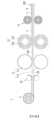
第1圖,為本發明一實施方式之前光模組之前光板製造設備示意圖。FIG. 1 is a schematic diagram of an optical board manufacturing equipment before an optical module assembly according to an embodiment of the present invention.
第2圖,為本發明一實施方式之前光模組之前光板製造方法步驟流程圖。FIG. 2 is a flow chart of steps in a method for manufacturing an optical panel before an optical module according to an embodiment of the present invention.
第3圖,為本發明一實施方式之前光模組之製造組裝設備示意圖。Fig. 3 is a schematic diagram of manufacturing and assembling equipment for optical modules before an embodiment of the present invention.
第4圖,為本發明一實施方式之前光模組之製造組裝方法步驟流程圖。Fig. 4 is a flow chart of the manufacturing and assembling method of the optical module before an embodiment of the present invention.
第5圖,為本發明一實施方式之前光模組之製造組裝流程與習知技術流程之比較示意圖。Fig. 5 is a schematic diagram comparing the manufacturing and assembling process of the optical module before an embodiment of the present invention with the prior art process.
誠如前述,鑒於前光板及其模組之製造組裝方式及設備,仍存有過於繁複、須不斷重複包裝、拆除包裝再進行加工或組裝等工序之缺失,導致前光板及其模組於加工便捷性還有時間效率上皆有其不足之處,且光學產品對於品質良率上之要求又更顯重要,因光線為相當敏感,只要產品略有些許損傷、髒汙等,就會大幅地影響後續使用上的狀態,而上述之繁瑣步驟即相當容易對光學產品之品質產生影響。為了解決該些問題,以提供更為簡便之前光板及其模組製造組裝方案,本發明人係經不斷構思調整進而提出一種前光模組之前光板製造、組裝方法及其設備,而透過減法工程技術手段,大幅提升製程效率與光學產品之產出良率,以下係先針對前光模組之前光板製造方法及設備進行說明。As mentioned above, in view of the manufacturing and assembly methods and equipment of the front light board and its modules, there are still lacks of processes such as being too complicated, repeating packaging, unpacking, and then processing or assembling, resulting in the front light board and its modules being in the process of processing. Convenience and time efficiency both have their deficiencies, and the quality and yield requirements of optical products are even more important, because light is very sensitive, as long as the product is slightly damaged or dirty, it will be greatly reduced Affect the state of subsequent use, and the above-mentioned cumbersome steps are quite easy to affect the quality of optical products. In order to solve these problems and provide a more convenient solution for the manufacture and assembly of the front light board and its module, the inventor proposed a method and equipment for the front light board manufacturing and assembly of the front light module through continuous conception and adjustment, and through subtractive engineering Technical means can greatly improve the process efficiency and the output yield of optical products. The following is a description of the front-optical board manufacturing method and equipment for the front-optical module.
請參閱第1圖,其係為本發明一實施方式之前光板製造設備示意圖,其中圖中所示之結構外型、尺規、比例等皆為利於示意說明本發明之結構特徵,非代表實際結構狀態,合先敘明。本發明之前光模組之前光板製造設備1,係包含一進料滾輪組10、一押印滾輪組11、一覆膠滾輪組12及一覆膜滾輪組13。Please refer to Figure 1, which is a schematic diagram of the light panel manufacturing equipment before an embodiment of the present invention, wherein the structural appearance, scales, scales, etc. shown in the figure are all helpful to illustrate the structural features of the present invention, and do not represent the actual structure The status is described first. The optical
進料滾輪組10用以展開一塑膠捲料2而形成一基材20,更具體地說,進料滾輪組10可具有多個不同功能的滾輪,例如用以將原先附著於塑膠捲料2上的其餘膜材撕除之滾輪,或是用以平整化基材20表面之滾輪,以藉此將捲狀的塑膠捲料2展開並形成可供以後續加工的基材20狀態。The feeding roller set 10 is used to unroll a
押印滾輪組11設於進料滾輪組10一側,供於基材20的上表面及/或下表面押印形成複數光學微結構201,押印滾輪組11係可選用表面具有與欲成形在基材20表面之光學微結構201相對應的凹槽或凸肋滾輪,以利於旋轉押印形成所需之光學圖案。其中,當押印滾輪組11欲於基材20之上表面及下表面皆押印形成光學微結構201時,押印滾輪組11可包含二個相對設置之押印滾輪;當押印滾輪組11係欲於基材20之上表面或下表面押印形成光學微結構201時,押印滾輪組11可包含一押印滾輪111及一支撐滾輪112,押印滾輪設於基材20之上側或下側,支撐滾輪112與押印滾輪111呈相對設置,以在押印滾輪111於基材20押印形成光學微結構201時,由相對側提供支撐力。於本實施方式中,係以押印滾輪111設於基材20上側以於基材20上表面形成光學微結構201,而支撐滾輪112對應押印滾輪111設置於基材20下側之應用狀態為例。The imprinting roller set 11 is arranged on one side of the feeding roller set 10, and is used for imprinting on the upper surface and/or the lower surface of the
覆膠滾輪組12設於押印滾輪組11一側,用以覆設一光學膠3於基材20的上表面及下表面,透過覆膠滾輪組12係可快速且平穩地將光學膠3塗佈於基材20的上表面和下表面,且採針對整條基材20以滾輪塗佈光學膠3之方式,除了不需要多重之覆膠工序外,也能避免氣泡產生。其中,具體實施上,覆膠滾輪組12可包含滾輪與噴膠嘴,藉由噴膠方式使滾輪附著光學膠3再塗覆於基材20表面,亦可使覆膠滾輪組12包含二膠捲121及二動力滾輪122,動力滾輪122係穿設於膠捲121之中空區域,且動力滾輪122與膠捲121分設於基材20的上下側,以於動力滾輪122旋轉時,帶動膠捲121而使光學膠3貼覆於基材20之上表面及下表面。The glue-covered roller set 12 is arranged on one side of the pressing roller set 11, and is used to coat an
覆膜滾輪組13設於覆膠滾輪組12一側,用以覆設一保護膜4於基材20之上表面及下表面,而形成一具有複數連續設置之光學圖案的前光板基材202。其中,覆膜滾輪組13亦可類同於覆膠滾輪組12之設置而具有二個膜捲和二個滾輪,將膜捲套設於滾輪上以利用滾輪之轉動而將保護膜4覆設置基材20之上表面和下表面。據此,透過所述之前光板製造設備1以滾輪組進行連續執行之製造工序,即可達到以減法工程提升加工便捷性之功效,在前光板之製造上,無須再透過繁複的膠材準備與塗膠工序,即可將光學膠3覆設於基材20上。而後為暫時地保護壓印有光學微結構201之基材20,係透過覆膜滾輪組13將保護膜4貼附於基材20上下表面以形成具有複數連續設置之光學圖案的前光板基材202,如此可達到暫存保護之功效。The film-
請繼續參閱第2圖,其係為本發明一實施方式之前光模組之前光板製造方法步驟流程圖,並請再一併參閱第1圖。所述前光板製造方法係用以於一產線連續執行,並包含以下步驟,首先,展開一塑膠捲料2以形成一基材20(步驟S10),而後利用一押印滾輪組11於基材20之上表面及/或下表面押印形成複數光學微結構201(步驟S11),接著再直接地利用一覆膠滾輪組12覆設一光學膠3於基材20的上表面及下表面(步驟S12),最後再直接利用一覆膜滾輪組13覆設一保護膜4於基材20之上表面及下表面,而形成一具有複數連續設置之光學圖案的前光板基材202(步驟S13)。據此,透過前述之連續工序,即可在基材20甫被押印形成有光學微結構201後,即塗佈光學膠3於基材20之上表面與下表面,如此相較於先加工製成每一片分離之前光板後再覆設光學膠之方式,此流程除有別於既有加工步驟,也提升了製程上的效率。透過覆膠滾輪組12於長條接續狀之基材20上實施塗膠作業,相對於針對每一片分離的板材塗佈光學膠而言,除了不需要考量板材分布位置或為避免在塗膠過程中偏移而需增設定位裝置外,也可均勻且快速地將光學膠3塗設至基材20上下表面。而後鑒於塗膠後的基材可能不會立即執行後續組裝或其他作業,在光學膠3覆設於基材20上表面和下表面之後,即進行保護膜4貼覆作業,以避免光學膠3受到汙染。是以,藉由上述之步驟流程,係可快速且便捷地製作出連續狀的前光板基材202,而與過往先製成各個分離狀的板材後再進行後續作業造成的諸多移動、加工工序差異甚鉅,並據此達到可提升製程效率與產品品質之功效。Please continue to refer to FIG. 2 , which is a flow chart of the optical panel manufacturing method before the optical module according to an embodiment of the present invention, and please also refer to FIG. 1 . The method for manufacturing the front light plate is used for continuous execution on a production line, and includes the following steps. First, a
接下來則請參閱第3圖,其係為本發明一實施方式之前光模組之製造組裝設備示意圖,其中圖中所示之結構外型、尺規、比例等皆為利於示意說明本發明之結構特徵,非代表實際結構狀態,合先敘明。基於相同的減法工程概念,本發明亦提出一種前光模組之製造組裝設備5,包含一進料滾輪組50、一押印滾輪組51、一覆膠滾輪組52、一切割裝置53、一第一組配裝置54及一第二組配裝置55。Next, please refer to Figure 3, which is a schematic diagram of the manufacturing and assembling equipment of the optical module before an embodiment of the present invention, wherein the structural appearance, rulers, scales, etc. shown in the figure are all helpful for illustrating the present invention. Structural features do not represent the actual structural state, and are described first. Based on the same concept of subtractive engineering, the present invention also proposes a manufacturing and assembling
進料滾輪組50用以展開一塑膠捲料2以形成一基材20,押印滾輪組51設於進料滾輪組50一側,供於基材20之上表面及/或下表面押印形成複數光學微結構201,覆膠滾輪組52設於押印滾輪組51一側,用以覆設一光學膠3於基材20的上表面及下表面,而形成一具有複數連續設置之光學圖案的前光板基料203。前述各滾輪組之作動係大致同於前光板製造設備之各滾輪組的作動,同樣係先將塑膠捲料2形成連續長條狀之基材20,再透過押印滾輪組51於上押印形成光學微結構201,而後再利用覆膠滾輪組52將光學膠覆設於基材20的上表面與下表面而形成欲直接進行切割之前光板基料203。The feeding roller set 50 is used to unroll a
切割裝置53設於覆膠滾輪組52一側,用以切割前光板基料203而形成複數前光板6。切割裝置53係可選用例如具有雷射或切割刀之設備,以利依據前光板6的尺寸將長條狀的前光板基料203切割形成分離之各前光板6。第一組配裝置54設於切割裝置53一側,用以直接組裝一光源模組7於各前光板6,其中光源模組7具有一電路基板70及複數LED71,LED71間隔設置於電路基板70,且電路基板70透過位於前光板6上表面之光學膠3進行固定,使LED71位於前光板6之側面。第一組配裝置54可例如為機械手臂等具備有移動功能之組件,以利於將光源模組7設置於前光板6上。第二組配裝置55則設於第一組配裝置54之一側,用以覆設一光學件8於各前光板6,光學件8透過位於前光板6上表面之光學膠3黏貼於前光板6上表面,進而組設形成一前光模組9。同樣地,第二組配裝置55也可為例如機械手臂之可搬移物件之組件,以將光學件8黏貼設置於前光板6上表面,其中光學件8可為玻璃面板或防眩光薄膜等。The cutting
據此,透過所述製造組裝設備5,係可連貫性地直接生產出前光模組9產品,並在該種設備特徵下,前光模組9於製造組裝上無須經過多次繁複的加工工序,各階段之滾輪組或裝置作動後即可傳輸至下一階段的裝置續以作業,而達到以減法工程提升加工便捷性之功效。同時在這樣的技術方案中,由於各組件無須不斷地執行貼覆或撕除動作,因此於生產過程中將可大幅避免沾塵或空氣進入膠體內的現象產生,進而讓產品保有優良的品質良率。Accordingly, through the manufacturing and assembling
進一步地,所述製造組裝設備5係可更包含一測試裝置56及一第三組配裝置57,而可將測試與最終組裝工序整合至製造組裝設備5。測試裝置56設於第二組配裝置55一側,用以針對各前光模組9進行點亮測試,第三組配模組57設於測試裝置56一側,用以將經過點亮測試之各前光模組9透過位於前光板6下表面之光學膠3黏貼於一反射式顯示面板A上。測試裝置56係用以針對前光模組9進行點亮與測試其發光狀態是否符合預期,具體地說可透過各類檢測儀予以實施。第三組配裝置57同樣可選用機械手臂予以實施,以利於將前光模組9藉由前光板6下表面之光學膠3黏貼於反射式顯示面板A上,實際應用上第三組配裝置57係可設定為移動前光模組9將其放置於反射式顯示面板A上而黏貼固定,或是設定為移動反射式顯示面板A使其黏貼於前光模組9之前光板6下表面皆可。Further, the
關於所述製造組裝設備5之各滾輪組特徵,進料滾輪組50可如前所述,具體上係具有二個用以將塑膠捲料2上供以保護膜料移除之滾輪,待保護膜料被移除後即形成可供以加工之長條連續狀基材20。押印滾輪組51則是透過滾輪於基材20之上表面及/或下表面押印形成光學微結構201,於一個實施狀態下,當押印滾輪組51係供於基材20之上表面或下表面押印形成光學微結構201時,押印滾輪組51包含一押印滾輪511及一支撐滾輪512,押印滾輪511設於基材20之上側或下側,且表面係設置有與光學微結構201相對應之複數凹槽或凸肋,支撐滾輪512與押印滾輪511呈相對設置,以在押印滾輪511於基材20押印形成光學微結構201時,由相對側提供支撐力,如此即可使押印滾輪511可平穩地於基材20押印形成具有高精準性之光學微結構201。覆膠滾輪組52亦可同於前段落所述內容,使用滾輪搭配噴膠嘴之方式構成,或是使覆膠滾輪組52包含有二膠捲521與二動力滾輪522亦可,動力滾輪522係穿設於膠捲521之中空區域,且動力滾輪522與膠捲521分設於基材20的上下側,以於動力滾輪522旋轉時,帶動膠捲521而使光學膠3貼覆於基材20之上表面及下表面,據此達到平順且快速塗佈膠體之功效。Regarding the characteristics of each roller group of the manufacturing and assembling
請繼續參閱第4圖,其係為本發明一實施方式之前光模組之製造組裝方法步驟流程圖,並請一併復搭配參閱第3圖。於本實施方式中係提出一種前光模組之製造組裝方法,用以於一產線連續執行,包含以下步驟,首先,展開一塑膠捲料2以形成一基材20(步驟S20),接著利用一押印滾輪組51於基材20之上表面及/或下表面押印形成複數光學微結構201(步驟S21),再利用一覆膠滾輪組52覆設一光學膠3於基材20的上表面及下表面,而形成一具有複數連續設置之光學圖案的前光板基料203(步驟S22),而後,係切割前光板基料203而形成複數前光板6(步驟S23),即可接續進行之後的作業。接著直接組裝一光源模組7於各前光板6,其中光源模組7具有一電路基板70及複數LED71,LED71係間隔設置於該電路基板70,且電路基板70透過位於前光板6上表面之光學膠3進行固定,使LED71位於前光板6之側面(步驟S24),再覆設一光學件8於各前光板6,光學件8係透過位於前光板6上表面之光學膠3黏貼於前光板6之上表面,進而組設形成一前光模組9(步驟S25)。據此,透過連續執行之各步驟,即可於產線實現一次性連續地產出前光板6並加以組裝形成前光模組9之目的,並藉由這樣的步驟流程,有效省略諸多繁複的加工工序,達到加工便捷化之功效。Please continue to refer to FIG. 4 , which is a flow chart of the manufacturing and assembling method of the optical module before an embodiment of the present invention, and please refer to FIG. 3 together. In this embodiment, a method for manufacturing and assembling a front light module is proposed, which is used for continuous execution in a production line, including the following steps. First, a
進一步地,組裝形成前光模組9後,所述製造組裝方法還可更包含針對各前光模組9進行點亮測試(步驟S26),及將經過點亮測試之各前光模組9透過位於前光板6下表面之光學膠3黏貼於一反射式顯示面板A上(步驟S27)之步驟。由於前光模組9係透過上述步驟所形成,因此在減法工程之基礎下,各元件無須透過相當繁瑣的步驟,因此加工過程中就能保持住一定的品質,進而在更後續加工上省略許多處理步驟。當前光模組9組設完畢後,需進行出光狀態之檢查,以確認整體效能,經過測試確認後即可將前光模組9黏貼於反射式顯示面板A上,而製成前光模組9之後端產品。Further, after assembling and forming the front
此外,由於前光模組9在後續的應用上,會是使用者直視且直接接觸之部件,因此考量前光模組9之出光狀態與保護力等因素,覆設於前光板6上表面的光學件8則可選擇為一防眩光薄膜或一玻璃面板,以調整前光模組9之出光或是達到保護前光板6之功效。In addition, since the front
另者,考慮前光模組9之體積大小以及可調整性等,可使電路基板70為一軟性印刷電路板,以具有可撓特性而更利於組裝與後續調整。In addition, considering the size and adjustability of the front
請續參閱第5圖,其係為本發明一實施方式之前光模組之製造組裝流程與習知技術流程之比較示意圖。圖中之(a)部分係表示習知前光模組組裝流程,圖中之(b)部分係表示本發明之流程。習知前光模組之組裝方式可謂是針對已製成之各個單獨存在之前光板,再進行多重加工工序。如第5圖之(a-1)~(a-8)所示,首先針對已製成的前光板撕除離型紙,(a-1)所示為撕除離型紙後的前光板。接著在撕除離型紙後的前光板一側表面設置光學膠,且在頂側之光學膠設置後需再覆蓋離型紙以保護光學膠,如(a-2)所示,但由於塗膠之前須先針對前光板做撕除離型紙之動作,所以在膠體設置於前光板後極易產生氣泡。接著再重複相同作業,在撕除離型紙後的前光板另一側表面設置光學膠,方式同於前一步驟,在底側之光學膠設置後同樣需再覆蓋離型紙以保護光學膠,如(a-3)所示。另者相同地,因為前光板必須先撕除覆蓋於上的離型紙,所以底側的光學膠也容易存有氣泡。Please continue to refer to FIG. 5 , which is a schematic diagram comparing the manufacturing and assembling process of the optical module before an embodiment of the present invention with the conventional technical process. Part (a) in the figure represents the assembly process of the conventional front light module, and part (b) in the figure represents the process of the present invention. The assembly method of the conventional front light module can be said to be multiple processing steps for each individually made front light plate. As shown in (a-1)~(a-8) of Figure 5, firstly, the release paper is torn off for the finished front light plate, and (a-1) shows the front light plate after the release paper is removed. Then install optical adhesive on the surface of the front light plate after the release paper is removed, and after the optical adhesive on the top side is installed, the release paper needs to be covered to protect the optical adhesive, as shown in (a-2), but because the glue is applied before The action of tearing off the release paper must be done on the front light board first, so it is easy to generate air bubbles after the colloid is placed on the front light board. Then repeat the same operation, install optical adhesive on the other side surface of the front light plate after tearing off the release paper, the method is the same as the previous step, after the optical adhesive on the bottom side is installed, it is also necessary to cover the release paper to protect the optical adhesive, such as (a-3) InstituteShow. In addition, because the release paper covering the front light plate must be removed first, the optical adhesive on the bottom side is also prone to air bubbles.
接著,於前光板上表面貼覆光學膜片,其作法為拿取光學膜片,並將光學膜片上的離型紙撕除,以及將留存於前光板上表面的光學膠的離型紙移除,再貼置光學膜片於前光板上表面的光學膠,以透過光學膠使光學膜固定於上,如(a-4)所示。在這樣的工序動作中,除了還須針對光學膠進行撕膜動作外,也因為此撕膜動作會導致光學膠暴露於空氣中,所以光學膜貼附後光學膠也容易再次產生氣泡與沾附髒汙。下一道工序為設置燈條至前光板,其作法為先取得本身設有背膠與離型膜之燈條,再將燈條上的離型膜撕除,使燈條透過背膠黏貼固定於前光板上表面,燈條之LED則對應位於前光板之側面,如(a-5)所示。燈條組裝完畢後,需再進行脫泡處理,其緣由在於前述之各工序因不斷地需進行撕除離型紙之動作,因此會造成氣泡形成於每層組件處,故需要經過脫泡程序以將存留之氣泡去除,如(a-6)所示。接著進行點亮測試,如(a-7)所示,以確認前光模組之出光狀況。待經過測試後,再將前光模組黏貼至反射式顯示面板上,如(a-8)所示。Next, stick an optical film on the front surface of the front light plate. The method is to take the optical film, tear off the release paper on the optical film, and remove the release paper of the optical glue remaining on the front light plate. , and then paste the optical film on the optical glue on the surface of the front light plate, so that the optical film can be fixed on it through the optical glue, as shown in (a-4). In such a process, in addition to tearing off the optical glue, the film tearing action will cause the optical glue to be exposed to the air, so after the optical film is attached, the optical glue is also prone to bubbles and adhesion again. dirty. The next process is to install the light bar to the front light panel. The method is to first obtain the light bar with its own adhesive and release film, and then tear off the release film on the light bar, so that the light bar can be pasted through the back adhesive and fixed on the On the upper surface of the front light plate, the LEDs of the light bar are correspondingly located on the side of the front light plate, as shown in (a-5). After the light strip is assembled, it needs to be degassed again. The reason is that the above-mentioned processes need to tear off the release paper continuously, which will cause bubbles to form at each layer of components, so it needs to go through the degassing process to Remove the remaining air bubbles, as shown in (a-6). Then perform a lighting test, as shown in (a-7), to confirm the light output status of the front light module. After being tested, the front light module is pasted on the reflective display panel, as shown in (a-8).
第5圖中的(b-1)~(b-5)則是本發明於切割形成前光板6後之製程作業,由於透過本發明之前光模組之前光板製造組裝方法及設備製成之前光板6,係於切割形成分離板材之前就已透過覆膠滾輪組52將光學膠3塗佈於基材20之上表面與下表面,因此無須再進行兩次的覆膠動作,且亦無需反覆的撕除與覆蓋離型紙,而可直接將光學件8以及光源模組7藉由前光板6上表面之光學膠3貼附固定。而後,因所述製造組裝方法及設備非如習知技術般需要不斷地撕膜,因此在組裝過程中不會有氣泡產生,而可省略了脫泡作業,直接對前光模組9進行點亮測試即可。在通過點亮測試後,就可以透過前光板6下表面之光學膠3黏貼固定於反射式顯示面板A上。(b-1)~(b-5) in Figure 5 are the process operations of the present invention after cutting and forming the front
由上述之比對明顯可知,所述製造組裝方法及設備相較於現有技術確實屬於減法工程而省略了許多會對產品造成破壞或影響的步驟。前光模組之製造組裝方法與設備係透過於產線中連續執行押印、覆膠及切割之動作而製成相互分離之各個已具有光學膠3的前光板6,後續僅需直接將光源模組7與光學件8透過已設置在前光板6上的光學膠3進行黏貼固定之作業,即可製成前光模組9,無須反覆地撕膜與重新蓋膜。在前光模組9之進一步組裝上,亦可省略脫泡作業而直接進行點亮測試,最終透過前光板6的光學膠3使前光模組9與反射式顯示面板A相互黏合固定。所述製造組裝方法及設備在省略諸多工序步驟後,對於生產出之產品不但無任何不良影響,更提供了具有更高質量之相關產品,確實達到在省略技術特徵後,可達到更為優異之生產品質,並有效地降低生產所需時間之功效。It is obvious from the above comparison that the manufacturing and assembling method and equipment are indeed subtractive engineering compared with the prior art and many steps that may damage or affect the product are omitted. The method and equipment for manufacturing and assembling the front light module is to make separate front
綜上所述,本發明之前光模組之製造組裝方法及其設備,係以減法工程之概念並利用滾輪加工方式,進而達到大幅增進加工便捷性之功效。透過上述技術手段,本發明係將前光板及前光模組之製造合併至同一產線內接續進行,由基材直接進行加工而製成具備光學膠之前光板,並後續製成前光模組,並非是將已製成之前光板再進行二次加工如覆膠之概念,據此可降低產品經由過多繁複的工序而影響品質之問題,並有效減縮生產時間與降低複雜度,亦即可提升加工上的便捷性。於此重述地,本發明所揭露之設備與方法,其重點在於透過連續生產方式一次地取得前光板、前光模組產品,進而可以減法工程達到提升加工便捷性、降低製造成本之功效,其整體流程步驟並非具有通常知識者可由申請時之通常知識任意省略即可輕易思及。本發明之設備與方法係基於特殊的前光板製造流程進而產出已具備光學膠之前光板,接續即可使用這樣的前光板結構以更快速且便捷的工序來製成前光模組,並據此繼續終端組裝應用,是以本發明揭示之設備與方法不可單獨拆解個別步驟,應將其整體流程一併視之始能得到本發明所強調之減法工程加工所帶來之便捷性優點。To sum up, the manufacturing and assembling method of the optical module and its equipment before the present invention are based on the concept of subtractive engineering and use the roller processing method to achieve the effect of greatly improving the convenience of processing. Through the above-mentioned technical means, the present invention merges the manufacture of the front light plate and the front light module into the same production line and proceeds successively. The base material is directly processed to make the front light plate with optical glue, and then the front light module is made , it is not the concept of secondary processing such as glue coating on the pre-made light board, so that the problem of product quality affected by too many complicated processes can be reduced, and the production time and complexity can be effectively reduced, which can also be improved. Convenience in processing. To reiterate here, the equipment and method disclosed in the present invention focus on obtaining the front light plate and front light module products at one time through the continuous production method, and then can achieve the effect of improving the convenience of processing and reducing the manufacturing cost by subtractive engineering. Its overall process steps do not have common knowledgeIt can be easily thought of by arbitrarily omitting the common knowledge at the time of application. The equipment and method of the present invention are based on a special front light plate manufacturing process to produce a front light plate with optical glue, and then use such a front light plate structure to make a front light module in a faster and more convenient process, and according to This continuation of the terminal assembly application means that the equipment and method disclosed in the present invention cannot be disassembled for individual steps, and the overall process should be viewed together to obtain the convenience advantages brought by the subtractive engineering process emphasized in the present invention.
2:塑膠捲料2: plastic coil
20:基材20: Substrate
201:光學微結構201:Optical Microstructure
203:前光板基料203: Front light plate base material
3:光學膠3: Optical glue
5:製造組裝設備5: Manufacture and assembly equipment
50:進料滾輪組50: Feed roller group
51:押印滾輪組51: Imprint roller set
511:押印滾輪511:Printing roller
512:支撐滾輪512: support roller
52:覆膠滾輪組52: Rubber-covered roller set
521:膠捲521: film
522:動力滾輪522: Power Roller
53:切割裝置53: Cutting device
54:第一組配裝置54: The first assembly device
55:第二組配裝置55: The second assembly device
56:測試裝置56: Test device
57:第三組配裝置57: The third assembly device
6:前光板6: Front light plate
7:光源模組7: Light source module
70:電路基板70: circuit substrate
71:LED71:LED
8:光學件8: Optics
9:前光模組9: Front light module
A:反射式顯示面板A: Reflective display panel
Claims (8)
Translated fromChinesePriority Applications (1)
| Application Number | Priority Date | Filing Date | Title |
|---|---|---|---|
| TW111113897ATWI790158B (en) | 2022-04-12 | 2022-04-12 | Manufacturing and assembling method for front light plate of front light module and equipment thereof |
Applications Claiming Priority (1)
| Application Number | Priority Date | Filing Date | Title |
|---|---|---|---|
| TW111113897ATWI790158B (en) | 2022-04-12 | 2022-04-12 | Manufacturing and assembling method for front light plate of front light module and equipment thereof |
Publications (2)
| Publication Number | Publication Date |
|---|---|
| TWI790158Btrue TWI790158B (en) | 2023-01-11 |
| TW202339938A TW202339938A (en) | 2023-10-16 |
Family
ID=86670097
Family Applications (1)
| Application Number | Title | Priority Date | Filing Date |
|---|---|---|---|
| TW111113897ATWI790158B (en) | 2022-04-12 | 2022-04-12 | Manufacturing and assembling method for front light plate of front light module and equipment thereof |
Country Status (1)
| Country | Link |
|---|---|
| TW (1) | TWI790158B (en) |
Citations (3)
| Publication number | Priority date | Publication date | Assignee | Title |
|---|---|---|---|---|
| CN1917998A (en)* | 2003-12-23 | 2007-02-21 | 上海向隆电子科技有限公司 | Methods of making a pattern of optical element shapes on a roll for use in making optical elements on or in substrates |
| CN101025451A (en)* | 2006-02-17 | 2007-08-29 | 开曼群岛商亚岗科技股份有限公司 | Mold belt-to-roller forming method and optical film with surface microstructure of resin layer |
| CN113064230A (en)* | 2021-04-01 | 2021-07-02 | 苏州茂立光电科技有限公司 | Roll-to-roll automatic film-attached light guide plate stack polishing and milling mechanism |
- 2022
- 2022-04-12TWTW111113897Apatent/TWI790158B/enactive
Patent Citations (3)
| Publication number | Priority date | Publication date | Assignee | Title |
|---|---|---|---|---|
| CN1917998A (en)* | 2003-12-23 | 2007-02-21 | 上海向隆电子科技有限公司 | Methods of making a pattern of optical element shapes on a roll for use in making optical elements on or in substrates |
| CN101025451A (en)* | 2006-02-17 | 2007-08-29 | 开曼群岛商亚岗科技股份有限公司 | Mold belt-to-roller forming method and optical film with surface microstructure of resin layer |
| CN113064230A (en)* | 2021-04-01 | 2021-07-02 | 苏州茂立光电科技有限公司 | Roll-to-roll automatic film-attached light guide plate stack polishing and milling mechanism |
Also Published As
| Publication number | Publication date |
|---|---|
| TW202339938A (en) | 2023-10-16 |
Similar Documents
| Publication | Publication Date | Title |
|---|---|---|
| CN110014717B (en) | Surface bonding device and bonding method thereof | |
| CN100581836C (en) | Method for making water-transfer printing paper by using printer to make pattern | |
| CN2910562Y (en) | Plate cold stamping apparatus for single printing article | |
| JP5837396B2 (en) | Optical sheet laminating method and apparatus, and pressure-sensitive adhesive sheet used therefor | |
| JP5867764B2 (en) | UV forming apparatus and method for roll-to-roll alignment | |
| CN104608370A (en) | Roll-to-roll based UV cured polymer film surface microstructure processing system and method | |
| JPWO2010018628A1 (en) | Film sticking apparatus, film sticking method, and electronic paper manufacturing method | |
| CN101738774A (en) | Ultrathin flexible liquid crystal display and manufacturing method thereof | |
| JP2019032415A (en) | Method for producing optical film with adhesive | |
| CN111806072A (en) | Micro-nano structure printing equipment, printing method and printed matter | |
| CN115598748B (en) | Display screen nano dimming film, LED display module and packaging method of LED display module | |
| CN106019693A (en) | Stripping device for polaroid release paper | |
| JP2014071381A (en) | Transfer body for optical film, optical film, image display device and production method of optical film | |
| CN103144458A (en) | Resin original plate for printing and method for manufacturing the same | |
| WO2020056922A1 (en) | Polarization assembly and display apparatus | |
| TWI790158B (en) | Manufacturing and assembling method for front light plate of front light module and equipment thereof | |
| JP2005156907A (en) | Display device manufacturing method and manufacturing apparatus thereof | |
| JPH0259046B2 (en) | ||
| CN104076421A (en) | Black-rimmed prism sheet, prism sheet manufacturing method and equipment and display device | |
| CN117289520B (en) | Manufacturing method of roll-to-roll flexible electronic paper membrane | |
| CN115230208A (en) | Front light plate manufacturing and assembling method and equipment of front light module | |
| TWI630382B (en) | Optical inspection method for display unit of flexible film structure, and virtual terminal unit used in the method | |
| CN106827924A (en) | Relief painting and preparation method thereof | |
| CN110626856A (en) | Sheet stock bottom dyestripping device | |
| KR20110016552A (en) | LGP Coating Equipment |