TWI789718B - Station for cleaner, cleaner system and controlling method thereof - Google Patents
Station for cleaner, cleaner system and controlling method thereofDownload PDFInfo
- Publication number
- TWI789718B TWI789718BTW110107586ATW110107586ATWI789718BTW I789718 BTWI789718 BTW I789718BTW 110107586 ATW110107586 ATW 110107586ATW 110107586 ATW110107586 ATW 110107586ATW I789718 BTWI789718 BTW I789718B
- Authority
- TW
- Taiwan
- Prior art keywords
- dust
- sweeper
- suction
- station
- motor
- Prior art date
Links
- 238000000034methodMethods0.000titleclaimsdescription38
- 230000005484gravityEffects0.000claimsabstractdescription29
- 230000000149penetrating effectEffects0.000claimsabstractdescription13
- 239000000428dustSubstances0.000claimsdescription1405
- 241001417527PempheridaeSpecies0.000claimsdescription849
- 230000008878couplingEffects0.000claimsdescription428
- 238000010168coupling processMethods0.000claimsdescription428
- 238000005859coupling reactionMethods0.000claimsdescription428
- 238000004140cleaningMethods0.000claimsdescription320
- 230000033001locomotionEffects0.000claimsdescription142
- 238000000926separation methodMethods0.000claimsdescription24
- 230000035939shockEffects0.000claimsdescription2
- 238000001514detection methodMethods0.000description185
- 230000006835compressionEffects0.000description156
- 238000007906compressionMethods0.000description156
- 229920006266Vinyl filmPolymers0.000description20
- 238000002360preparation methodMethods0.000description20
- 238000003825pressingMethods0.000description19
- 238000010408sweepingMethods0.000description11
- 238000009826distributionMethods0.000description9
- 230000000694effectsEffects0.000description9
- 235000019645odorNutrition0.000description9
- 238000005452bendingMethods0.000description8
- 238000007689inspectionMethods0.000description7
- 238000007789sealingMethods0.000description7
- 210000000707wristAnatomy0.000description6
- 238000013459approachMethods0.000description5
- 238000005520cutting processMethods0.000description5
- 210000000245forearmAnatomy0.000description5
- 239000010813municipal solid wasteSubstances0.000description5
- 238000010586diagramMethods0.000description4
- 239000012530fluidSubstances0.000description4
- 230000001154acute effectEffects0.000description3
- 238000010438heat treatmentMethods0.000description3
- 238000003032molecular dockingMethods0.000description3
- 230000005540biological transmissionEffects0.000description2
- 230000008859changeEffects0.000description2
- 238000012986modificationMethods0.000description2
- 230000004048modificationEffects0.000description2
- 230000008569processEffects0.000description2
- 230000009286beneficial effectEffects0.000description1
- 230000008901benefitEffects0.000description1
- 230000000903blocking effectEffects0.000description1
- 238000001816coolingMethods0.000description1
- 238000001914filtrationMethods0.000description1
- 210000003811fingerAnatomy0.000description1
- 210000004247handAnatomy0.000description1
- 230000036541healthEffects0.000description1
- 210000004932little fingerAnatomy0.000description1
- 238000012423maintenanceMethods0.000description1
- 238000005259measurementMethods0.000description1
- 230000008450motivationEffects0.000description1
- 238000011045prefiltrationMethods0.000description1
- 238000012545processingMethods0.000description1
- 230000003014reinforcing effectEffects0.000description1
- 230000004043responsivenessEffects0.000description1
- 238000006467substitution reactionMethods0.000description1
- 210000003813thumbAnatomy0.000description1
Images


Classifications
- A—HUMAN NECESSITIES
- A47—FURNITURE; DOMESTIC ARTICLES OR APPLIANCES; COFFEE MILLS; SPICE MILLS; SUCTION CLEANERS IN GENERAL
- A47L—DOMESTIC WASHING OR CLEANING; SUCTION CLEANERS IN GENERAL
- A47L9/00—Details or accessories of suction cleaners, e.g. mechanical means for controlling the suction or for effecting pulsating action; Storing devices specially adapted to suction cleaners or parts thereof; Carrying-vehicles specially adapted for suction cleaners
- A47L9/28—Installation of the electric equipment, e.g. adaptation or attachment to the suction cleaner; Controlling suction cleaners by electric means
- A47L9/2868—Arrangements for power supply of vacuum cleaners or the accessories thereof
- A47L9/2873—Docking units or charging stations
- A—HUMAN NECESSITIES
- A47—FURNITURE; DOMESTIC ARTICLES OR APPLIANCES; COFFEE MILLS; SPICE MILLS; SUCTION CLEANERS IN GENERAL
- A47L—DOMESTIC WASHING OR CLEANING; SUCTION CLEANERS IN GENERAL
- A47L9/00—Details or accessories of suction cleaners, e.g. mechanical means for controlling the suction or for effecting pulsating action; Storing devices specially adapted to suction cleaners or parts thereof; Carrying-vehicles specially adapted for suction cleaners
- A47L9/28—Installation of the electric equipment, e.g. adaptation or attachment to the suction cleaner; Controlling suction cleaners by electric means
- A47L9/2868—Arrangements for power supply of vacuum cleaners or the accessories thereof
- A47L9/2884—Details of arrangements of batteries or their installation
- A—HUMAN NECESSITIES
- A47—FURNITURE; DOMESTIC ARTICLES OR APPLIANCES; COFFEE MILLS; SPICE MILLS; SUCTION CLEANERS IN GENERAL
- A47L—DOMESTIC WASHING OR CLEANING; SUCTION CLEANERS IN GENERAL
- A47L5/00—Structural features of suction cleaners
- A47L5/12—Structural features of suction cleaners with power-driven air-pumps or air-compressors, e.g. driven by motor vehicle engine vacuum
- A47L5/22—Structural features of suction cleaners with power-driven air-pumps or air-compressors, e.g. driven by motor vehicle engine vacuum with rotary fans
- A47L5/24—Hand-supported suction cleaners
- A—HUMAN NECESSITIES
- A47—FURNITURE; DOMESTIC ARTICLES OR APPLIANCES; COFFEE MILLS; SPICE MILLS; SUCTION CLEANERS IN GENERAL
- A47L—DOMESTIC WASHING OR CLEANING; SUCTION CLEANERS IN GENERAL
- A47L7/00—Suction cleaners adapted for additional purposes; Tables with suction openings for cleaning purposes; Containers for cleaning articles by suction; Suction cleaners adapted to cleaning of brushes; Suction cleaners adapted to taking-up liquids
- A47L7/0095—Suction cleaners or attachments adapted to collect dust or waste from power tools
- A—HUMAN NECESSITIES
- A47—FURNITURE; DOMESTIC ARTICLES OR APPLIANCES; COFFEE MILLS; SPICE MILLS; SUCTION CLEANERS IN GENERAL
- A47L—DOMESTIC WASHING OR CLEANING; SUCTION CLEANERS IN GENERAL
- A47L9/00—Details or accessories of suction cleaners, e.g. mechanical means for controlling the suction or for effecting pulsating action; Storing devices specially adapted to suction cleaners or parts thereof; Carrying-vehicles specially adapted for suction cleaners
- A47L9/0009—Storing devices ; Supports, stands or holders
- A47L9/0063—External storing devices; Stands, casings or the like for the storage of suction cleaners
- A—HUMAN NECESSITIES
- A47—FURNITURE; DOMESTIC ARTICLES OR APPLIANCES; COFFEE MILLS; SPICE MILLS; SUCTION CLEANERS IN GENERAL
- A47L—DOMESTIC WASHING OR CLEANING; SUCTION CLEANERS IN GENERAL
- A47L9/00—Details or accessories of suction cleaners, e.g. mechanical means for controlling the suction or for effecting pulsating action; Storing devices specially adapted to suction cleaners or parts thereof; Carrying-vehicles specially adapted for suction cleaners
- A47L9/10—Filters; Dust separators; Dust removal; Automatic exchange of filters
- A47L9/106—Dust removal
- A—HUMAN NECESSITIES
- A47—FURNITURE; DOMESTIC ARTICLES OR APPLIANCES; COFFEE MILLS; SPICE MILLS; SUCTION CLEANERS IN GENERAL
- A47L—DOMESTIC WASHING OR CLEANING; SUCTION CLEANERS IN GENERAL
- A47L9/00—Details or accessories of suction cleaners, e.g. mechanical means for controlling the suction or for effecting pulsating action; Storing devices specially adapted to suction cleaners or parts thereof; Carrying-vehicles specially adapted for suction cleaners
- A47L9/10—Filters; Dust separators; Dust removal; Automatic exchange of filters
- A47L9/16—Arrangement or disposition of cyclones or other devices with centrifugal action
- A47L9/1683—Dust collecting chambers; Dust collecting receptacles
- A—HUMAN NECESSITIES
- A47—FURNITURE; DOMESTIC ARTICLES OR APPLIANCES; COFFEE MILLS; SPICE MILLS; SUCTION CLEANERS IN GENERAL
- A47L—DOMESTIC WASHING OR CLEANING; SUCTION CLEANERS IN GENERAL
- A47L9/00—Details or accessories of suction cleaners, e.g. mechanical means for controlling the suction or for effecting pulsating action; Storing devices specially adapted to suction cleaners or parts thereof; Carrying-vehicles specially adapted for suction cleaners
- A47L9/22—Mountings for motor fan assemblies
- A—HUMAN NECESSITIES
- A47—FURNITURE; DOMESTIC ARTICLES OR APPLIANCES; COFFEE MILLS; SPICE MILLS; SUCTION CLEANERS IN GENERAL
- A47L—DOMESTIC WASHING OR CLEANING; SUCTION CLEANERS IN GENERAL
- A47L9/00—Details or accessories of suction cleaners, e.g. mechanical means for controlling the suction or for effecting pulsating action; Storing devices specially adapted to suction cleaners or parts thereof; Carrying-vehicles specially adapted for suction cleaners
- A47L9/28—Installation of the electric equipment, e.g. adaptation or attachment to the suction cleaner; Controlling suction cleaners by electric means
- A47L9/2805—Parameters or conditions being sensed
- A47L9/281—Parameters or conditions being sensed the amount or condition of incoming dirt or dust
- A47L9/2815—Parameters or conditions being sensed the amount or condition of incoming dirt or dust using optical detectors
- A—HUMAN NECESSITIES
- A47—FURNITURE; DOMESTIC ARTICLES OR APPLIANCES; COFFEE MILLS; SPICE MILLS; SUCTION CLEANERS IN GENERAL
- A47L—DOMESTIC WASHING OR CLEANING; SUCTION CLEANERS IN GENERAL
- A47L9/00—Details or accessories of suction cleaners, e.g. mechanical means for controlling the suction or for effecting pulsating action; Storing devices specially adapted to suction cleaners or parts thereof; Carrying-vehicles specially adapted for suction cleaners
- A47L9/28—Installation of the electric equipment, e.g. adaptation or attachment to the suction cleaner; Controlling suction cleaners by electric means
- A47L9/2836—Installation of the electric equipment, e.g. adaptation or attachment to the suction cleaner; Controlling suction cleaners by electric means characterised by the parts which are controlled
- A47L9/2842—Suction motors or blowers
- A—HUMAN NECESSITIES
- A47—FURNITURE; DOMESTIC ARTICLES OR APPLIANCES; COFFEE MILLS; SPICE MILLS; SUCTION CLEANERS IN GENERAL
- A47L—DOMESTIC WASHING OR CLEANING; SUCTION CLEANERS IN GENERAL
- A47L9/00—Details or accessories of suction cleaners, e.g. mechanical means for controlling the suction or for effecting pulsating action; Storing devices specially adapted to suction cleaners or parts thereof; Carrying-vehicles specially adapted for suction cleaners
- A47L9/32—Handles
- A47L9/322—Handles for hand-supported suction cleaners
- A—HUMAN NECESSITIES
- A47—FURNITURE; DOMESTIC ARTICLES OR APPLIANCES; COFFEE MILLS; SPICE MILLS; SUCTION CLEANERS IN GENERAL
- A47L—DOMESTIC WASHING OR CLEANING; SUCTION CLEANERS IN GENERAL
- A47L2201/00—Robotic cleaning machines, i.e. with automatic control of the travelling movement or the cleaning operation
- A47L2201/02—Docking stations; Docking operations
- A47L2201/022—Recharging of batteries
- A—HUMAN NECESSITIES
- A47—FURNITURE; DOMESTIC ARTICLES OR APPLIANCES; COFFEE MILLS; SPICE MILLS; SUCTION CLEANERS IN GENERAL
- A47L—DOMESTIC WASHING OR CLEANING; SUCTION CLEANERS IN GENERAL
- A47L2201/00—Robotic cleaning machines, i.e. with automatic control of the travelling movement or the cleaning operation
- A47L2201/02—Docking stations; Docking operations
- A47L2201/024—Emptying dust or waste liquid containers
Landscapes
- Engineering & Computer Science (AREA)
- Mechanical Engineering (AREA)
- Robotics (AREA)
- Electric Vacuum Cleaner (AREA)
- Filters For Electric Vacuum Cleaners (AREA)
- Electric Suction Cleaners (AREA)
- Nozzles For Electric Vacuum Cleaners (AREA)
- Selective Calling Equipment (AREA)
- Control Of Position, Course, Altitude, Or Attitude Of Moving Bodies (AREA)
- Automobile Manufacture Line, Endless Track Vehicle, Trailer (AREA)
- Manufacturing Of Printed Wiring (AREA)
- Manipulator (AREA)
Abstract
Description
Translated fromChinese本發明涉及一種清掃機站、一種清掃機系統、以及一種控制清掃機站的方法,更具體地說,涉及一種清掃機、一種清掃機站,配置以將儲存在清掃機中的灰塵吸入清掃機站中、一種清掃機系統、以及一種控制清掃機站的方法。The present invention relates to a sweeper station, a sweeper system, and a method of controlling a sweeper station, and more particularly, to a sweeper, a sweeper station configured to draw dust stored in the sweeper into the sweeper station, a sweeper system, and a method of controlling a sweeper station.
一般來說,清掃機是指藉由使用電力抽吸空氣來吸取小垃圾或灰塵並將垃圾或灰塵填入設置在產品中的塵箱的電器。這樣的清掃機一般稱為真空吸塵器。In general, a sweeper refers to an electrical appliance that sucks small garbage or dust by sucking air using electric power and fills the garbage or dust into a dust box provided in a product. Such sweeping machines are commonly referred to as vacuum cleaners.
清掃機可以分為由使用者直接移動以進行清掃操作的手動清掃機;以及在自主行進時進行清掃操作的自動清掃機。根據清掃機的形狀,手動清掃機可以分為罐筒式吸塵器、直立式吸塵器、手持式吸塵器、棒式吸塵器等。Sweepers can be classified into manual sweepers that are directly moved by a user to perform a sweeping operation; and automatic sweepers that perform a sweeping operation while autonomously traveling. According to the shape of the sweeper, manual sweepers can be divided into canister vacuum cleaners, upright vacuum cleaners, hand-held vacuum cleaners, stick vacuum cleaners, etc.
罐筒式吸塵器在過去被廣泛用作家庭清掃機。然而,最近越來越傾向於使用其中塵箱和清掃機主體一體設置的手持式吸塵器和棒式吸塵器以提高使用的便利性。Canister vacuums have been widely used as household sweepers in the past. However, recently, there is an increasing tendency to use a hand-held vacuum cleaner and a stick-type vacuum cleaner in which a dust box and a sweeper main body are integrally provided to improve convenience of use.
至於罐筒式吸塵器,主體和吸氣口藉由橡膠軟管或管道連接,在某些情況下,可以在吸氣口裝有刷子的狀態下使用罐筒式吸塵器。As for canister cleaners, the main body and the suction port are connected by a rubber hose or pipe, and in some cases, it is possible to use the canister cleaner with a brush attached to the suction port.
手持式吸塵器(手持真空吸塵器)具有最大的便攜性,而且重量很輕。然而,由於手持式吸塵器的長度較短,對於清掃區域可能有所限制。因此,手持式吸塵器用於清掃局部區域,例如辦公桌、沙發或車輛內部。Handheld vacuum cleaners (handheld vacuum cleaners) are designed for maximum portability and are very light in weight. However, due to the short length of the handheld vacuum cleaner, there may be restrictions on the cleaning area. Therefore, handheld vacuum cleaners are used for cleaning localized areas, such as desks, sofas or the interior of vehicles.
使用者可以在站立時使用棒式吸塵器,因此可以不彎腰進行清掃操作。因此,棒式吸塵器有利於使用者在該區域內移動時清掃寬闊區域。手持式吸塵器可以用於清掃狹窄的空間,而棒式吸塵器可以用於清掃寬闊的空間,也可以用於使用者的手無法到達的高處。近來提供了模組化的棒式吸塵器,這樣就可以主動地更換清掃機的類型,並用於清掃各種地方。Users can use the stick cleaner while standing, so they can clean without bending over. Thus, the stick cleaner facilitates cleaning of a wide area as the user moves within the area. Hand-held vacuum cleaners can be used to clean narrow spaces, while stick vacuum cleaners can be used to clean wide spaces or high places that the user's hands cannot reach. Recently, stick cleaners are provided which are modular, so that the type of sweeper can be actively changed and used to clean various places.
此外,最近還使用一種清掃機器人,其無須使用者操作即可自主地進行清掃操作。清掃機器人在欲清掃的區域內自主行進時,藉由抽吸地板上諸如灰塵等異物,自動清掃該欲清掃的區域。In addition, recently, a cleaning robot that can perform cleaning operations autonomously without a user's operation is also used. When the cleaning robot travels autonomously in the area to be cleaned, it automatically cleans the area to be cleaned by sucking foreign objects such as dust on the floor.
為此,清掃機器人包括距離感測器,配置以檢測與障礙物的距離,如安裝在待清掃區域的傢俱、辦公用品或牆壁;以及用於移動清掃機器人的左滾輪和右滾輪。To this end, the cleaning robot includes a distance sensor configured to detect a distance from obstacles such as furniture, office supplies, or walls installed in an area to be cleaned; and left and right rollers for moving the cleaning robot.
在這種情況下,左滾輪和右滾輪配置以分別藉由左滾輪馬達和右滾輪馬達而旋轉,清掃機器人在清掃房間的同時,藉由操作左滾輪馬達和右滾輪馬達自主地改變方向。In this case, the left and right rollers are configured to be rotated by the left and right roller motors, respectively, and the cleaning robot autonomously changes directions by operating the left and right roller motors while cleaning the room.
然而,由於相關技術中的手持式吸塵器、棒式吸塵器或清掃機器人具有容量較小的塵箱,用於儲存收集的灰塵,這給使用者帶來不便,因為使用者需要頻繁清空塵箱。However, since the hand-held vacuum cleaner, stick cleaner or cleaning robot in the related art has a dust box with a small capacity for storing collected dust, this causes inconvenience to the user because the user needs to frequently empty the dust box.
此外,由於在清空塵箱的過程中灰塵會飛散,因此存在的問題是飛散的灰塵會損害使用者的健康。In addition, since the dust is scattered during the emptying of the dust box, there is a problem that the scattered dust damages the user's health.
此外,如果不將殘留的灰塵從塵箱中清除,就會出現清掃機的抽吸力衰減的問題。In addition, if the residual dust is not removed from the dust box, there will be a problem of attenuation of the suction power of the sweeper.
此外,如果不將殘留的灰塵從塵箱中清除,出現的問題是殘留的灰塵會產生令人厭惡的氣味。In addition, if the remaining dust is not removed from the dust box, there arises a problem that the remaining dust produces a nasty smell.
同時,專利文獻韓國專利第2020-0074054A號揭露了一種真空吸塵器和一種對接站。Meanwhile, the patent document Korean Patent No. 2020-0074054A discloses a vacuum cleaner and a docking station.
清掃機站的結構,其與集塵容器對接,該結構設置成向上。在這種情況下,可以使用一種將塵箱與清掃機分離然後只耦接塵箱的方法。然而,存在著不便之處,即使用者需要直接將塵箱與清掃機分離。The structure of the sweeper station, which interfaces with the dust collection container, is arranged upwards. In this case, a method of detaching the dust box from the sweeper and coupling only the dust box can be used. However, there is an inconvenience that the user needs to directly separate the dust box from the sweeper.
此外,在上述真空吸塵器中,延伸管的軸線、吸氣口的軸線和集塵容器的軸線相互平行設置。在這種情況下,即使安裝有集塵容器的清掃機可以耦接於清掃機站,但為了將空氣和灰塵引入清掃機站中,灰塵和空氣可能流經的流動路徑需要彎曲至少兩次。由於這個原因,存在著流動路徑的結構複雜、收集灰塵的效率變差的問題。Furthermore, in the above vacuum cleaner, the axis of the extension pipe, the axis of the suction port, and the axis of the dust collecting container are arranged in parallel to each other. In this case, even though a sweeper equipped with a dust collection container can be coupled to the sweeper station, in order to introduce air and dust into the sweeper station, a flow path through which the dust and air may flow needs to be bent at least twice. For this reason, there is a problem that the structure of the flow path is complicated, and the efficiency of dust collection becomes poor.
同時,專利文獻日本專利第2017-189453號揭露了一種用於清除手棒式吸塵器上的灰塵的站裝置。Meanwhile, the patent document Japanese Patent No. 2017-189453 discloses a station device for removing dust from a hand stick vacuum cleaner.
在真空吸塵器中,延伸管的軸線、吸氣口的軸線和塵箱的軸線彼此平行設置。在站裝置中,耦接於真空吸塵器的塵箱的結構被設置成指向上方。亦即,真空吸塵器安裝在站的上部。In the vacuum cleaner, the axis of the extension pipe, the axis of the suction port and the axis of the dust box are arranged parallel to each other. In the station arrangement, the structure coupled to the dust box of the vacuum cleaner is arranged to point upwards. That is, the vacuum cleaner is mounted on the upper part of the station.
然而,當真空吸塵器安裝在站上時塵箱曝露在外面,這可能會給使用者帶來不適。However, when the vacuum cleaner is mounted on the station, the dust box is exposed, which may cause discomfort to the user.
此外,如果在真空吸塵器的主體與站的上部耦接的狀態下施加外部衝擊,真空吸塵器的主體很可能會掉下來。In addition, if an external impact is applied in a state where the main body of the vacuum cleaner is coupled to the upper portion of the stand, the main body of the vacuum cleaner is likely to fall.
專利文獻美國專利第2020-0129025 A1號揭露了一種與棒式吸塵器耦接的塵箱。Patent document US Patent No. 2020-0129025 A1 discloses a dust box coupled with a stick vacuum cleaner.
在該專利文獻的塵箱和吸塵器的組合中,真空吸塵器設置成耦接於塵箱。In the dust box and vacuum cleaner combination of this patent document, the vacuum cleaner is arranged to be coupled to the dust box.
該專利文獻的塵箱具有耦接於真空吸塵器的上表面。The dust box of this patent document has an upper surface coupled to a vacuum cleaner.
然而,耦接於真空吸塵器的塵箱的上表面相對於地面的高度較低,這給使用者帶來不適,因為使用者需要彎曲腰部將吸塵器耦接於塵箱。However, the height of the upper surface of the dust box coupled with the vacuum cleaner relative to the ground is low, which brings discomfort to the user because the user needs to bend the waist to couple the vacuum cleaner to the dust box.
此外,還有一個問題是使用者需要直接組裝吸塵器和塵箱。In addition, there is a problem that the user needs to directly assemble the vacuum cleaner and the dust box.
此外,還有一個問題是無法壓縮在真空吸塵器中的灰塵以清除殘留在吸塵器中的灰塵。In addition, there is a problem that it is impossible to compress the dust in the vacuum cleaner to remove the dust remaining in the vacuum cleaner.
同時,專利文獻美國專利第10595692 B2揭露了一種具有清掃機器人的碎屑箱的排放站。Meanwhile, patent document US Pat. No. 10595692 B2 discloses a discharge station of a debris bin with a cleaning robot.
在上述專利文獻中,設置讓清掃機器人停靠的一站,該站具有流通路徑,灰塵通過該流通路徑沿垂直於地面的方向被抽吸。此外,還設置感測器,感測清掃機器人與站之間的對接,並且在對接過程中,讓馬達操作以抽吸清掃機器人中的灰塵。In the above patent document, a station for the cleaning robot to stop is provided, and the station has a circulation path through which dust is sucked in a direction perpendicular to the ground. In addition, a sensor is provided to sense the docking between the cleaning robot and the station, and during docking, the motor is operated to suck dust in the cleaning robot.
然而,存在的問題是上述專利文獻的站沒有用來耦接棒式吸塵器的結構。此外,只能在清掃機器人耦接於站的連接器的狀態下才能進行抽吸灰塵,但不具有用來檢查清掃機是否有耦接好、是否有固定好清掃機以及吸氣口是否開啟或關閉的組件。However, there is a problem that the station of the above patent document has no structure for coupling the stick cleaner. In addition, dust can only be sucked when the cleaning robot is coupled to the connector of the station, but there is no way to check whether the cleaning machine is well coupled, whether the cleaning machine is fixed, and whether the suction port is open or not. Closed component.
此外,根據該專利文獻,站的高度相對低,而用於從清掃機器人中抽吸灰塵的集塵馬達設置在其上側。Furthermore, according to this patent document, the height of the station is relatively low, and the dust collection motor for suctioning dust from the cleaning robot is provided on its upper side.
因為這種結構,即使是在將棒式吸塵器安裝在站上的情況下,其上安裝有棒式吸塵器的站的整體重心也集中在其上側。因此,存在著站容易因衝擊而傾倒的問題。Because of this structure, even in the case where the stick cleaner is mounted on the stand, the entire center of gravity of the stand on which the stick cleaner is mounted is concentrated on its upper side. Therefore, there is a problem that the station is easily toppled by impact.
本發明是為解決相關技術中清掃機系統的上述問題,本發明的一個目的是提供一種清掃機站、一種清掃機系統、以及一種控制該清掃機站的方法,能夠消除由於使用者需要頻繁清空塵箱而造成的不便。The present invention is to solve the above-mentioned problems of the cleaning machine system in the related art. One object of the present invention is to provide a cleaning machine station, a cleaning machine system, and a method for controlling the cleaning machine station, which can eliminate the need for frequent emptying by the user. Inconvenience caused by the dust box.
此外,本發明的一個目的是提供一種清掃機站、一種清掃機系統、以及一種控制該清掃機站的方法,能夠防止在清空塵箱時灰塵飛散。Furthermore, an object of the present invention is to provide a sweeper station, a sweeper system, and a method of controlling the sweeper station capable of preventing dust from flying when emptying a dust box.
此外,本發明的一個目的是提供一種清掃機站、一種清掃機系統、以及一種控制該清掃機站的方法,其中,當清掃機耦接於清掃機站時,可以檢測清掃機的耦接、可以自動固定清掃機、可以開啟清掃機站的吸氣口(門)、並可以開啟清掃機的塵箱的遮蓋。Furthermore, it is an object of the present invention to provide a sweeper station, a sweeper system, and a method of controlling the sweeper station, wherein when the sweeper is coupled to the sweeper station, it is possible to detect the coupling of the sweeper, It can automatically fix the sweeper, open the suction port (door) of the sweeper station, and open the cover of the dust box of the sweeper.
此外,本發明的一個目的是提供一種清掃機站、一種清掃機系統、以及一種控制該清掃機站的方法,不須使用者額外操作就能夠清除塵箱中的灰塵。Furthermore, an object of the present invention is to provide a sweeper station, a sweeper system, and a method of controlling the sweeper station, which can remove dust from a dust box without additional operations by a user.
此外,本發明的一個目的是提供一種清掃機站、一種清掃機系統、以及一種控制該清掃機站的方法,能夠藉由防止塵箱中有殘留的灰塵來消除由於殘留的灰塵所引起的異味。Furthermore, an object of the present invention is to provide a sweeper station, a sweeper system, and a method of controlling the sweeper station capable of eliminating odors due to residual dust by preventing residual dust from remaining in the dust box. .
此外,本發明的一個目的是提供一種清掃機站、以及一種清掃機系統,其中當清掃機與清掃機站耦接時,可以穩定地支撐清掃機和清掃機站而不傾倒。Furthermore, an object of the present invention is to provide a sweeper station, and a sweeper system, in which the sweeper and the sweeper station can be stably supported without toppling when the sweeper and the sweeper station are coupled.
此外,本發明的一個目的是提供一種清掃機站、以及一種清掃機系統,其中,可以在安裝有延伸管和清掃模組的狀態下安裝清掃機。Furthermore, an object of the present invention is to provide a sweeper station, and a sweeper system, in which the sweeper can be installed in a state where the extension pipe and the sweeper module are installed.
此外,本發明的一個目的是提供一種清掃機站、以及一種清掃機系統,即使清掃機在安裝狀態下,也能夠最大限度地減少水平面上所佔用的空間。Furthermore, it is an object of the present invention to provide a sweeper station, and a sweeper system, which minimize the space occupied on a horizontal surface even when the sweeper is installed.
此外,本發明的一個目的是提供一種清掃機站、以及一種清掃機系統,能夠最大限度地減少集塵流動力的損失。Furthermore, it is an object of the present invention to provide a sweeper station, and a sweeper system, capable of minimizing the loss of dust collection flow power.
此外,本發明的一個目的是提供一種清掃機站、以及一種清掃機系統,當清掃機在安裝狀態下,從外面看不見塵箱中的灰塵。Furthermore, it is an object of the present invention to provide a sweeper station, and a sweeper system, in which dust in a dust box is not visible from the outside when the sweeper is installed.
此外,本發明的一個目的是提供一種清掃機站、以及一種清掃機系統,讓使用者能夠彎腰就將清掃機耦接於清掃機站。In addition, it is an object of the present invention to provide a sweeper station and a sweeper system that allow users to couple the sweeper to the sweeper station by bending over.
此外,本發明的一個目的是提供一種清掃機站、以及一種清掃機系統,讓使用者在握持清掃機的狀態下,僅藉由簡單地移動他/她的手腕或前臂,就能輕鬆地將清掃機耦接於清掃機站。Furthermore, it is an object of the present invention to provide a sweeper station, and a sweeper system that allow a user to easily move the sweeper by simply moving his/her wrist or forearm while holding the sweeper. A sweeper is coupled to the sweeper station.
此外,本發明的一個目的是提供一種清掃機站、以及一種清掃機系統,其中棒式吸塵器和清掃機器人可以同時耦接到清掃機站,並且根據需要,棒式吸塵器的塵箱中的灰塵和清掃機器人的塵箱中的灰塵可以被選擇性地清除。Furthermore, it is an object of the present invention to provide a sweeper station, and a sweeper system, wherein a stick cleaner and a sweeping robot can be coupled to the sweeper station at the same time, and the dust in the dust box of the stick cleaner and the The dust in the dust box of the cleaning robot can be selectively removed.
為實現上述目的,根據本發明的清掃機系統可以包括:清掃機包括:抽吸部,具有空氣流經的抽吸流動路徑、抽吸馬達,配置以產生抽吸力,用於沿抽吸部抽吸空氣、灰塵分離部,具有抽吸馬達,配置以產生抽吸力,用於沿抽吸部抽吸空氣、灰塵分離部,具有兩個或更多的旋風部件,配置以從透過抽吸部引入的空氣中分離灰塵、塵箱,配置以儲存由灰塵分離部分離的灰塵、以及把手,包括朝抽吸馬達延伸的第一延伸部、朝塵箱延伸的第二延伸部、以及連接第一延伸部和第二延伸部的握持部;以及清掃機站,包括:耦接於塵箱的耦接部、集塵部,將塵箱中的灰塵收集於其中、以及吸塵模組,具有集塵馬達,配置以產生抽吸力,用於將塵箱中的灰塵吸入集塵部中。To achieve the above object, the cleaning machine system according to the present invention may include: the cleaning machine includes: a suction part having a suction flow path through which air flows, a suction motor configured to generate suction force for Suction air, dust separation section with a suction motor configured to generate suction force for suctioning air along the suction section, dust separation section with two or more cyclone elements configured to suction Separate dust from the air introduced from the part, a dust box configured to store the dust separated by the dust separating part, and a handle including a first extension extending toward the suction motor, a second extension extending toward the dust box, and connecting the second extension to the suction motor. An extension part and a gripping part of the second extension part; and the sweeper station, including: a coupling part coupled to the dust box, a dust collecting part, in which dust in the dust box is collected, and a dust suction module, having The dust collecting motor is configured to generate suction force for sucking the dust in the dust box into the dust collecting part.
在這種情況下,清掃機系統可以包括假想的平面,該平面包括假想的抽吸流動路徑通過線,在縱向上穿透抽吸流動路徑;以及假想的抽吸馬達軸線,藉由延伸抽吸馬達的旋轉軸來界定。In this case, the sweeper system may include an imaginary plane comprising an imaginary suction flow path through-line longitudinally penetrating the suction flow path; and an imaginary suction motor axis by extending the suction flow path The axis of rotation of the motor is defined.
該平面可以包括假想的握持部通過線,形成在握持部的縱向上,並穿透握持部內部。The plane may include an imaginary grip passing line formed in a longitudinal direction of the grip and penetrate inside the grip.
該平面可以包括假想的集塵馬達軸線,藉由延伸集塵馬達的旋轉軸來界定。The plane may include an imaginary dust collection motor axis, defined by extending the rotation axis of the dust collection motor.
該平面可以包括假想的塵箱通過線,在縱向上穿透塵箱。The plane may include an imaginary dust box passage line, penetrating the dust box in the longitudinal direction.
當清掃機耦接於清掃機站時,該平面可以穿透集塵馬達的至少一部分。The plane may penetrate at least a portion of the dust collection motor when the sweeper is coupled to the sweeper station.
抽吸流動路徑通過線可以相交於假想的抽吸馬達軸線。The suction flow path through line may intersect the imaginary suction motor axis.
抽吸流動路徑通過線可以相交於假想的握持部通過線,該握持部通過線形成在握持部的縱向上,並穿透握持部內部。The suction flow path passing line may intersect with an imaginary grip passing line formed in a longitudinal direction of the grip and penetrating inside the grip.
當清掃機耦接於清掃機站時,抽吸馬達軸線可以相交於假想的集塵馬達軸線,該集塵馬達軸線藉由延伸該集塵馬達的軸線來界定,以及從地面至抽吸馬達軸線與集塵馬達軸線之間的交會點的高度可以等於或小於清掃機站的最大高度。When a sweeper is coupled to a sweeper station, the suction motor axis may intersect an imaginary collection motor axis defined by extending the collection motor axis and from the floor to the suction motor axis The height of the intersection point with the dust collection motor axis may be equal to or less than the maximum height of the sweeper station.
清掃機站可以進一步包括流動路徑部分,其具有流動路徑,流動路徑在清掃機與清掃機站耦接時讓塵箱的內部空間與集塵部的內部空間彼此連通。The cleaner station may further include a flow path part having a flow path which communicates the inner space of the dust box and the inner space of the dust collecting part with each other when the cleaner and the cleaner station are coupled.
在這種情況下,在清掃機與清掃機站耦接的狀態下,在縱向上穿透塵箱之假想的塵箱通過線和藉由延伸集塵馬達的旋轉軸來界定之假想的集塵馬達軸線可以在流動路徑部分相交。In this case, in the state where the sweeper is coupled to the sweeper station, the imaginary dust box passage line penetrating the dust box in the longitudinal direction and the imaginary dust collection box defined by extending the rotation axis of the dust collection motor The motor axes may intersect at portions of the flow paths.
流動路徑部分可以包括:第一流動路徑,配置以在清掃機與清掃機站相耦接時與塵箱的內部空間相通;以及第二流動路徑,形成在相對於第一流動路徑的一預定角度處,並配置以使第一流動路徑與集塵部的內部空間彼此相通。The flow path portion may include: a first flow path configured to communicate with an inner space of the dust box when the sweeper is coupled to the sweeper station; and a second flow path formed at a predetermined angle with respect to the first flow path and configured so that the first flow path communicates with the inner space of the dust collecting part.
第一流動路徑的長度可以小於或等於第二流動路徑的長度。The length of the first flow path may be less than or equal to the length of the second flow path.
清掃機站可以進一步包括殼體,配置以界定清掃機站的外觀,並容納集塵部和吸塵模組。The sweeper station may further include a housing configured to define an appearance of the sweeper station and accommodate the dust collecting part and the dust suction module.
清掃機耦接於殼體的側面。當清掃機與清掃機站耦接時,假想的握持部通過線可以相交於假想的集塵馬達軸線,該握持部通過線穿透握持部內部並在形成為柱狀的握持部的縱向上延伸,該集塵馬達軸線藉由延伸集塵馬達的軸線來界定,以及握持部通過線與集塵馬達軸線的交會點可以位於殼體中。The cleaning machine is coupled to the side of the housing. When the sweeper is coupled to the sweeper station, an imaginary grip passing line can intersect the imaginary dust collection motor axis, the grip passing line penetrating the interior of the grip and at the grip formed as a column The axis of the dust collection motor is defined by extending the axis of the dust collection motor, and the intersection point of the handle passing line and the axis of the dust collection motor may be located in the housing.
根據本發明的清掃機系統含可以包括假想的平面,該平面包括握持部通過線和集塵馬達軸線。The sweeper system according to the present invention may include an imaginary plane including the grip passing line and the dust collection motor axis.
該平面可以包括握持部通過線和假想的抽吸流動路徑通過線,該抽吸流動路徑通過線在縱向上穿透抽吸流動路徑。The plane may include a grip passage line and an imaginary suction flow path passage line that penetrates the suction flow path in the longitudinal direction.
在根據本發明的清掃機系統中,當清掃機耦接於清掃機站時,握持部通過線相交於抽吸流動路徑通過線,以及從地面到握持部通過線與抽吸流動路徑通過線之間的交會點的高度可以小於或等於殼體的最大高度。In the sweeper system according to the invention, when the sweeper is coupled to the sweeper station, the grip pass line intersects the suction flow path pass line, and the floor to the grip pass line passes the suction flow path The height of the intersection between lines may be less than or equal to the maximum height of the shell.
該平面可以包括集塵馬達軸線;以及假想的抽吸馬達軸線,其藉由延伸抽吸馬達的旋轉來軸界定。The plane may include a dust collection motor axis; and an imaginary suction motor axis defined by extending the rotation axis of the suction motor.
當清掃機耦接於清掃機站時,集塵馬達軸線可以相交於抽吸馬達軸線。When the sweeper is coupled to the sweeper station, the dust collection motor axis may intersect the suction motor axis.
該平面可以包括集塵馬達軸線和塵箱通過線。The plane may include the axis of the dust collecting motor and the passing line of the dust box.
當清掃機耦接於清掃機站時,集塵馬達軸線可以相交於塵箱通過線。When the sweeper is coupled to the sweeper station, the axis of the dust collection motor may intersect the dust box passing line.
在清掃機耦接於清掃機站的狀態下,從地面到握持部的最短距離可以是60公分或更多。With the sweeper coupled to the sweeper station, the shortest distance from the ground to the grip may be 60 cm or more.
在抽吸馬達軸線與至地面垂直線之間的夾角可以為40度或更大及95度或更小。The angle between the suction motor axis and the vertical to the ground can be 40 degrees or more and 95 degrees or less.
在抽吸馬達軸線與至地面垂直線之間的夾角可以為43度或更大及90度或更小。The angle between the suction motor axis and the vertical to the ground can be 43 degrees or more and 90 degrees or less.
該平面可以包括抽吸流動路徑通過線和握持部通過線。The plane may include the suction flow path through-line and the grip through-line.
當清掃機耦接於清掃機站時,該平面可以穿透集塵馬達的至少一部分,而且抽吸馬達軸線對該平面的正交投影可以相交於抽吸流動路徑通過線。When the sweeper is coupled to the sweeper station, the plane may penetrate at least a portion of the dust collection motor, and an orthogonal projection of the suction motor axis to the plane may intersect the suction flow path passing line.
耦接部可以垂直地設置在集塵馬達上方,集塵馬達比抽吸馬達重,從集塵馬達到耦接部的距離可以比從抽吸馬達到耦接部的距離長。The coupling part may be vertically disposed above the dust collection motor, the dust collection motor is heavier than the suction motor, and the distance from the dust collection motor to the coupling part may be longer than that from the suction motor to the coupling part.
抽吸馬達軸線和集塵馬達軸線可以彼此相交。The suction motor axis and the dust collection motor axis may intersect each other.
當清掃機耦接於清掃機站時,耦接部可以設置在假想的抽吸流動路徑通過線與假想的集塵馬達軸線之間,該抽吸流動路徑通過線在縱向上穿透抽吸流動路徑,該集塵馬達軸線藉由延伸該集塵馬達的旋轉軸來界定。When the sweeper is coupled to the sweeper station, the coupling portion may be disposed between an imaginary suction flow path through line that penetrates the suction flow longitudinally and the imaginary dust collection motor axis The path, the axis of the dust collection motor is defined by extending the rotation axis of the dust collection motor.
清掃機站可以進一步包括固定構件,配置以從塵箱的外部朝塵箱移動,以便固定塵箱。The sweeper station may further include a fixing member configured to move toward the dust box from outside the dust box so as to fix the dust box.
當清掃機耦接於清掃機站時,固定構件可以配置在抽吸流動路徑通過線與集塵馬達軸線之間。When the sweeper is coupled to the sweeper station, the fixing member may be disposed between the suction flow path passing line and the dust collection motor axis.
清掃機站還可以包括開蓋元件,配置以開啟塵箱的排放遮蓋。The sweeper station may also include an opening element configured to open the discharge cover of the dust box.
當清掃機耦接於清掃機站時,開蓋元件可以設置在抽吸流動路徑通過線與集塵馬達軸線之間。When the sweeper is coupled to the sweeper station, the cover opening element may be disposed between the suction flow path passing line and the dust collection motor axis.
當該清掃機耦接於清掃機站時,把手位於比假想的抽吸馬達軸線更遠離地面,該抽吸馬達軸線藉由延伸抽吸馬達的軸線來界定。When the sweeper is coupled to the sweeper station, the handle is located further from the ground than the imaginary suction motor axis defined by extending the suction motor axis.
清掃機可以進一步包括電池,配置以向抽吸馬達供電。The sweeper may further include a battery configured to power the suction motor.
當清掃機耦接於清掃機站時,電池可以位於比假想的抽吸馬達軸線更遠離地面,該抽吸馬達軸線藉由延伸抽吸馬達的軸線來界定。When the sweeper is coupled to the sweeper station, the battery may be located further from the ground than the imaginary suction motor axis defined by extending the axis of the suction motor.
當清掃機耦接於清掃機站時,在假想的抽吸馬達軸線與假想的集塵馬達軸線之間的夾角可以為40度或更大及95度或更小,該抽吸馬達軸線藉由延伸抽吸馬達的軸線來界定,該集塵馬達軸線藉由延伸集塵馬達的軸線來界定。When the sweeper is coupled to the sweeper station, the angle between the imaginary suction motor axis and the imaginary dust collection motor axis, which is defined by Extending the axis of the suction motor is defined by extending the axis of the dust collection motor.
在抽吸馬達軸線與集塵馬達軸線之間的夾角可以為43度或更大及90度或更小。The included angle between the axis of the suction motor and the axis of the dust collection motor may be 43 degrees or more and 90 degrees or less.
當清掃機的主體耦接於清掃機站時,塵箱的縱軸線與清掃機站的縱軸線可以彼此相交。The longitudinal axis of the dust box and the longitudinal axis of the sweeper station may intersect each other when the body of the sweeper is coupled to the sweeper station.
當清掃機的主體耦接於清掃機站時,灰塵分離部的流動軸線與清掃機站的縱軸線可以彼此相交。The flow axis of the dust separation part and the longitudinal axis of the sweeper station may intersect each other when the body of the sweeper is coupled to the sweeper station.
塵箱可以與清掃機的主體分離,當塵箱耦接於清掃機站時,塵箱的縱軸線與清掃機站的縱軸線可以彼此相交。The dust box may be separate from the main body of the sweeper, and the longitudinal axis of the dust box and the longitudinal axis of the sweeper station may intersect each other when the dust box is coupled to the sweeper station.
當清掃機的主體耦接於清掃機站時,抽吸馬達的旋轉軸和清掃機站的縱軸可以彼此相交。When the body of the sweeper is coupled to the sweeper station, the rotational axis of the suction motor and the longitudinal axis of the sweeper station may intersect each other.
抽吸馬達的旋轉軸可以設置為與塵箱的縱軸線平行。The axis of rotation of the suction motor can be arranged parallel to the longitudinal axis of the dust box.
抽吸馬達的旋轉軸可以配置為與灰塵分離部的流動軸線平行。The rotation shaft of the suction motor may be arranged parallel to the flow axis of the dust separating part.
清掃機的主體在與抽吸部的縱向相交的方向上移動並耦接於耦接部。The main body of the sweeper moves in a direction intersecting the longitudinal direction of the suction part and is coupled to the coupling part.
相交於抽吸部的縱向的方向可以是垂直於抽吸部的縱向的方向。The direction intersecting the longitudinal direction of the suction part may be a direction perpendicular to the longitudinal direction of the suction part.
相交於抽吸部的縱向的方向可以是平行於地面的方向。A direction intersecting the longitudinal direction of the suction portion may be a direction parallel to the ground.
清掃機的主體可以在相交於抽吸部的縱向的方向上移動、在抽吸部的縱向上移動、然後耦接於耦接部。The main body of the sweeper may move in a direction intersecting the longitudinal direction of the suction part, move in the longitudinal direction of the suction part, and then be coupled to the coupling part.
清掃機的主體可以沿清掃機站的縱軸線移動並耦接於耦接部。The main body of the sweeper is movable along the longitudinal axis of the sweeper station and coupled to the coupling portion.
清掃機的主體可以沿清掃機站的縱軸線移動、在垂直於抽吸部的縱向上移動、然後耦接於耦接部。The main body of the sweeper can move along the longitudinal axis of the sweeper station, move in a longitudinal direction perpendicular to the suction portion, and then be coupled to the coupling portion.
清掃機的主體可以垂直地向下移動並耦接於耦接部。The main body of the sweeper can vertically move downward and be coupled to the coupling part.
為了實現上述目標,根據本發明的清掃機站可以包括:殼體;耦接部,配置在殼體中並包含耦接表面,第一清掃機耦接於該耦接表面;集塵部,容納在殼體中,配置在耦接部下方,並配置以擷取第一清掃機的塵箱中的灰塵;集塵馬達,容納在殼體中,配置在集塵部下方,並配置以產生抽吸力,用於抽吸塵箱中的灰塵;固定元件,配置在耦接部上,並配置以固定第一清掃機;以及控制元件,配置以控制耦接部、固定元件、門元件、開蓋元件、拉桿元件、以及集塵馬達。In order to achieve the above object, the cleaning machine station according to the present invention may include: a housing; a coupling part disposed in the housing and including a coupling surface to which the first cleaning machine is coupled; a dust collecting part for accommodating In the casing, it is arranged under the coupling part and configured to pick up the dust in the dust box of the first cleaning machine; the dust collection motor is housed in the casing, arranged under the dust collecting part, and configured to generate suction. Suction, used to suck the dust in the dust box; the fixing element, configured on the coupling part, and configured to fix the first cleaning machine; and the control element, configured to control the coupling part, the fixing element, the door element, and the opening cover elements, rod elements, and dust collection motors.
在這種情況下,耦接部可以進一步包括從耦接表面突出的導引突出部;以及耦接感測器,配置在導引突出部上,並配置以檢測第一清掃機是否在準確位置上耦接。In this case, the coupling part may further include a guide protrusion protruding from the coupling surface; and a coupling sensor disposed on the guide protrusion and configured to detect whether the first sweeper is at an accurate position on coupling.
當第一清掃機在準確位置耦接時,耦接感測器可以傳輸表示第一清掃機被耦接的信號。The coupling sensor may transmit a signal indicating that the first sweeping machine is coupled when the first sweeping machine is coupled at the exact location.
固定元件可以包括:固定構件,配置以當第一清掃機耦接於耦接部時,從塵箱的外部朝塵箱移動以便固定塵箱;以及固定驅動部,配置以提供用於移動固定構件的動力。The fixing member may include: a fixing member configured to move toward the dust box from the outside of the dust box to fix the dust box when the first cleaner is coupled to the coupling part; motivation.
控制元件可以從耦接感測器接收表示第一清掃機被耦接的信號。The control element may receive a signal from the coupling sensor indicating that the first sweeper is coupled.
當控制元件從耦接感測器接收到表示清掃機被耦接的信號時,控制元件可以操作固定驅動部,使得固定構件固定塵箱。When the control element receives a signal from the coupling sensor indicating that the sweeper is coupled, the control element may operate the fixing drive so that the fixing member fixes the dust box.
固定元件可以進一步包括能夠檢測固定構件的運動的固定檢測部。The fixing element may further include a fixing detection portion capable of detecting movement of the fixing member.
當固定檢測部檢測到固定構件移動到固定構件固定塵箱的位置時,固定檢測部可以傳送表示塵箱被固定的信號。When the fixing detecting part detects that the fixing member moves to a position where the fixing member fixes the dust box, the fixing detecting part may transmit a signal indicating that the dust box is fixed.
控制元件可以從固定檢測部接收表示塵箱被固定的信號,並停止固定驅動部的操作。The control element may receive a signal indicating that the dust box is fixed from the fixing detection part, and stop the operation of the fixing driving part.
當清掃機的至少一部分在耦接部的確切位置上被耦接時,固定驅動部可以操作以移動固定構件。The stationary drive is operable to move the stationary member when at least a portion of the sweeper is coupled at the precise location of the coupling.
根據本發明的清掃機可以進一步包括門元件,包含門,耦接於耦接表面,並配置以開啟或關閉形成在耦接表面上的灰塵通孔,使得將外部空氣可以引入殼體中。The sweeper according to the present invention may further include a door member including a door coupled to the coupling surface and configured to open or close a dust through hole formed on the coupling surface so that external air may be introduced into the housing.
門元件可以包括:門,鉸鍊式地耦接到耦接表面,並配置以開啟或關閉灰塵通孔;以及門馬達,配置以提供用於旋轉門的動力。The door element may include: a door hingedly coupled to the coupling surface and configured to open or close the dust passage hole; and a door motor configured to provide power for rotating the door.
在這種情況下,當塵箱被固定時,控制元件可以操作門馬達以開啟灰塵通孔。In this case, when the dust box is fixed, the control element may operate the door motor to open the dust through hole.
當塵箱固定時,門馬達可以操作以使門旋轉並開啟灰塵通孔。When the dust box is fixed, the door motor can be operated to rotate the door and open the dust through hole.
門元件可以進一步包括開門/關門檢測部,配置以檢測門是否開啟或關閉。The door element may further include a door opening/closing detection part configured to detect whether the door is opened or closed.
當開門/關門檢測部檢測到門被開啟時,開門/關門檢測部可以傳送表示門被開啟的信號。When the door opening/closing detecting section detects that the door is opened, the door opening/closing detecting section may transmit a signal indicating that the door is opened.
基於是否向第一清掃機的電池供電,控制元件可以檢查第一清掃機是否被耦接。Based on whether power is supplied to the battery of the first sweeper, the control element may check whether the first sweeper is coupled.
控制元件可以接收表示門已被開啟的信號,並停止門馬達的操作。The control element may receive a signal indicating that the door has been opened and stop operation of the door motor.
根據本發明的清掃機可以進一步包括開蓋元件,配置在耦接部上,並配置以開啟塵箱的排放遮蓋。The sweeper according to the present invention may further include a cover opening member disposed on the coupling portion and configured to open the discharge cover of the dust box.
開蓋元件可以包括:推動突出部,配置以當第一清掃機被耦接時移動;以及開蓋驅動部,配置以提供用於移動推動突出部的動力。The cover opening member may include: a pushing protrusion configured to move when the first sweeper is coupled; and a cover opening driving part configured to provide power for moving the pushing protrusion.
在這種情況下,當門被開啟時,控制元件可以操作開蓋驅動部以開啟排放遮蓋。In this case, when the door is opened, the control element may operate the cover opening drive to open the discharge cover.
開蓋元件可以進一步包括開蓋檢測部,配置以檢測排放遮蓋是否被開啟。The cap opening member may further include a cap opening detection portion configured to detect whether the discharge cover is opened.
當開蓋檢測部檢測到排放遮蓋被開啟時,開蓋檢測部可以傳送表示排放遮蓋被開啟的信號。When the cover opening detection part detects that the discharge cover is opened, the cover open detection part may transmit a signal indicating that the discharge cover is opened.
控制元件可以接收表示排放遮蓋被開啟的信號,並停止開蓋驅動部的操作。The control element may receive a signal indicating that the discharge cover is opened, and stop the operation of the cover opening driving part.
根據本發明的清掃機可以進一步包括拉桿元件,容納在殼體中,並配置以行程移動和旋轉,以拉動第一清掃機的塵箱壓縮桿。The sweeper according to the present invention may further include a pull rod member accommodated in the housing and configured to move and rotate with a stroke to pull the dust box compression rod of the first sweeper.
拉桿元件可以包括行程驅動馬達,配置在殼體中,並配置以提供用於行程移動拉桿臂的動力。The drawbar member may include a stroke drive motor disposed in the housing and configured to provide power for stroke-moving the drawbar arm.
在這種情況下,控制元件可以操作行程驅動馬達,以使拉桿臂移動到等於或高於塵箱壓縮桿的高度。In this case, the control element can operate the travel drive motor to move the drawbar arm to a height equal to or higher than the dust box compression lever.
拉桿元件可以進一步包括臂部運動檢測部,配置以檢測拉桿臂的運動。The tie rod element may further include an arm movement detection portion configured to detect movement of the tie rod arm.
當臂部運動檢測部檢測到拉桿臂移動到等於或高於塵箱壓縮桿的高度時,臂部運動檢測部可以傳送表示拉桿臂被行程移動到目標位置的信號。When the arm motion detection part detects that the pull rod arm moves to a height equal to or higher than the dust box compression rod, the arm motion detection part may transmit a signal indicating that the pull rod arm is stroked to a target position.
控制元件可以接收表示拉桿臂被行程移動到目標位置的信號,並停止行程驅動馬達的運行。The control element may receive a signal indicating that the drawbar arm is stroked to a target position and stop operation of the stroke drive motor.
同時,拉桿元件可以進一步包括旋轉驅動馬達,配置以提供用於旋轉拉桿臂的動力。Meanwhile, the tie rod member may further include a rotation driving motor configured to provide power for rotating the tie rod arm.
在這種情況下,當拉桿臂移動到等於或高於塵箱壓縮桿的高度時,控制元件可以操作旋轉驅動馬達,使拉桿臂旋轉到拉桿臂的一端可以推動塵箱壓縮桿的位置。In this case, when the pull arm moves to a height equal to or higher than the dust box compression rod, the control element can operate the rotary drive motor to rotate the pull rod arm to a position where one end of the pull rod arm can push the dust box compression rod.
當拉桿臂移動到等於或高於塵箱壓縮桿的高度時,旋轉驅動馬達可以運行。When the pull rod arm moves to a height equal to or higher than the dust box compression rod, the rotary drive motor can operate.
當臂部運動檢測部檢測到拉桿臂旋轉到拉桿臂可以推動塵箱壓縮桿的位置時,臂部運動檢測部可以傳送表示拉桿臂旋轉到目標位置的信號。When the arm motion detection part detects that the pull rod arm is rotated to a position where the pull rod arm can push the dust box compression rod, the arm motion detection part may transmit a signal indicating that the pull rod arm has rotated to a target position.
控制元件可以接收表示拉桿臂旋轉到目標位置的信號,並停止旋轉驅動馬達的運行。The control element may receive a signal indicative of rotation of the drawbar arm to a target position and deactivate the rotation drive motor.
同時,當拉桿臂移動到拉桿臂的該端可以拉動塵箱壓縮桿的位置時,控制元件可以在拉桿臂拉動塵箱壓縮桿的方向上操作行程驅動馬達。At the same time, when the pull rod arm moves to the position where the end of the pull rod arm can pull the dust box compression rod, the control element can operate the travel drive motor in the direction in which the pull rod arm pulls the dust box compression rod.
當拉桿臂移動到拉桿臂的該端可以推動塵箱壓縮桿的位置時,可以運行行程驅動馬達。When the drawbar arm is moved to a position where the end of the drawbar arm can push the dust box compression lever, the travel drive motor can be operated.
當臂部運動檢測部檢測到當壓縮桿被拉動,拉桿臂移動到目標位置時,臂部運動檢測部可以傳送表示拉桿臂被拉動的信號。When the arm motion detection part detects that the pull rod arm moves to the target position when the compression lever is pulled, the arm motion detection part may transmit a signal indicating that the pull rod arm is pulled.
控制元件可以接收表示拉桿臂被拉動的信號,並停止行程驅動馬達的運行。The control element may receive a signal indicating that the drawbar arm is pulled and stop operation of the travel drive motor.
控制元件可以操作集塵馬達,並在集塵馬達運行期間操作行程驅動馬達,使得拉桿臂至少拉動一次塵箱壓縮桿。The control element can operate the dust collection motor, and operate the travel drive motor during the operation of the dust collection motor, so that the pull rod arm pulls the dust box compression rod at least once.
在集塵馬達的操作過程中,行程驅動馬達可以至少操作一次。During the operation of the dust collecting motor, the stroke driving motor may be operated at least once.
在集塵馬達的操作結束後,控制元件可以在門被關閉的方向上操作門馬達。The control element may operate the door motor in a direction in which the door is closed after the operation of the dust collecting motor is finished.
在集塵馬達的操作結束後,可以操作門馬達。After the operation of the dust collecting motor is finished, the door motor can be operated.
在集塵馬達的操作結束後,控制元件可以操作旋轉驅動馬達,以使拉桿臂的該端旋轉並返回到原始位置,並且控制元件可以操作行程驅動馬達,以使拉桿臂的高度返回到原始位置。After the operation of the dust collection motor is over, the control element can operate the rotary drive motor to make the end of the drawbar arm rotate and return to the original position, and the control element can operate the stroke drive motor to return the height of the drawbar arm to the original position .
當門被關閉時,控制元件可以操作固定驅動部,使得固定構件可以釋放塵箱。When the door is closed, the control element can operate the stationary drive so that the stationary member can release the dust box.
當門關閉灰塵通孔時,固定驅動部可以運行。When the door closes the dust through hole, the stationary drive can operate.
為了實現上述目標,根據本發明的清掃機系統可以包括:清掃機,包含:抽吸部;抽吸馬達,配置以產生抽吸力,用於沿抽吸部抽吸空氣;灰塵分離部,配置以從透過抽吸部引入的空氣中分離灰塵;塵箱,配置以儲存由灰塵分離部分離的灰塵;排放遮蓋,配置以選擇性地開啟或關閉塵箱的下側;以及壓縮構件,配置以在塵箱的內部空間中移動,以將塵箱中的灰塵向下壓縮;以及清掃機站,包含:耦接部,塵箱耦接於該耦接部;開蓋元件,配置以將排放遮蓋與塵箱分離;以及集塵部,配置在耦接部下方。In order to achieve the above object, the cleaning machine system according to the present invention may include: a cleaning machine including: a suction part; a suction motor configured to generate a suction force for sucking air along the suction part; a dust separating part configured to separate dust from air introduced through the suction part; a dust box configured to store the dust separated by the dust separating part; a discharge cover configured to selectively open or close a lower side of the dust box; and a compression member configured to moves within the interior space of the dust box to compress the dust in the dust box downward; and a sweeper station including: a coupling portion to which the dust box is coupled; an opening member configured to cover the discharge separated from the dust box; and a dust collecting part disposed under the coupling part.
在這種情況下,當排放遮蓋從塵箱分離時,塵箱中的灰塵可以藉由重力被擷取到集塵部中。In this case, when the discharge cover is separated from the dust box, the dust in the dust box can be picked up into the dust collecting part by gravity.
此外,當排放遮蓋從塵箱分離時,壓縮構件可以從塵箱的上側移動到下側,從而將塵箱中的灰塵擷取到集塵部。In addition, when the discharge cover is separated from the dust box, the compression member may move from the upper side to the lower side of the dust box, thereby picking up the dust in the dust box to the dust collecting part.
此外,清掃機還可以包括壓縮桿,設置在塵箱或灰塵分離部外部並連接於壓縮構件。In addition, the sweeper may further include a compression rod disposed outside the dust box or the dust separation part and connected to the compression member.
在這種情況下,當壓縮桿被外力向下移動時,壓縮構件可以從塵箱的上側移動到下側,以將塵箱中的灰塵擷取到集塵部中。In this case, when the compression lever is moved downward by the external force, the compression member may move from the upper side to the lower side of the dust box to pick up the dust in the dust box into the dust collecting part.
此外,耦接部可以包括:耦接表面,形成在相對於地面的一預定角度處,並配置成使得塵箱的下表面耦接於耦接表面;以及塵箱導引表面,連接於耦接表面,並形成為與塵箱的外表面對應的形狀。In addition, the coupling part may include: a coupling surface formed at a predetermined angle with respect to the ground and configured such that a lower surface of the dust box is coupled to the coupling surface; and a dust box guide surface connected to the coupling surface. surface, and formed into a shape corresponding to the outer surface of the dust box.
此外,清掃機站可以包括第一驅動部,配置以旋轉耦接表面。Additionally, the sweeper station may include a first drive configured to rotate the coupling surface.
在這種情況下,當塵箱耦接於耦接表面時,第一驅動部可以旋轉耦接表面與地面平行。In this case, when the dust box is coupled to the coupling surface, the first driving part may rotate the coupling surface to be parallel to the ground.
此外,清掃機還可以包括:鉸鏈部,配置以使排放遮蓋相對於塵箱旋轉;以及耦接桿,配置以將排放遮蓋耦接於塵箱。In addition, the sweeper may further include: a hinge part configured to rotate the discharge cover relative to the dust box; and a coupling lever configured to couple the discharge cover to the dust box.
在這種情況下,開蓋元件可以藉由將耦接桿從塵箱分離而選擇性地開啟或關閉塵箱的下側。此外,塵箱中的灰塵可以藉由在排放遮蓋從塵箱分離時所發生的衝擊力被擷取到集塵部中。In this case, the cover opening member may selectively open or close the lower side of the dust box by detaching the coupling lever from the dust box. In addition, the dust in the dust box can be picked up into the dust collecting part by the impact force that occurs when the discharge cover is separated from the dust box.
此外,清掃機站可以包括:耦接感測器,配置以檢測塵箱是否耦接於耦接部;以及開蓋驅動部,配置以當塵箱耦接於耦接部時操作開蓋元件。In addition, the cleaning machine station may include: a coupling sensor configured to detect whether the dust box is coupled to the coupling part; and a cover opening driving part configured to operate the cover opening element when the dust box is coupled to the coupling part.
此外,清掃機站還可以包括:門,配置以將從塵箱分離的排放遮蓋耦接於塵箱;以及門馬達,配置以將門旋轉到一側。Additionally, the sweeper station may further include: a door configured to couple the discharge cover detached from the dust box to the dust box; and a door motor configured to rotate the door to one side.
此外,清掃機站可以包括第一流動部,配置以讓空氣流向抽吸部。Additionally, the sweeper station may include a first flow portion configured to flow air to the suction portion.
在這種情況下,流向抽吸部的空氣可以將塵箱中的灰塵擷取到集塵部中。In this case, the air flowing to the suction part can pick up the dust in the dust box into the dust collection part.
此外,清掃機站可以包括:密封構件,配置以密封抽吸部;以及第二流動部,配置以讓空氣流向塵箱。In addition, the sweeper station may include: a sealing member configured to seal the suction part; and a second flow part configured to let air flow toward the dust box.
在這種情況下,流向塵箱的空氣可以將塵箱中的灰塵擷取到集塵部中。In this case, the air flowing toward the dust box can pick up the dust in the dust box into the dust collecting part.
此外,第二流動部可以包括:排放部,配置以排放空氣,以及驅動部,配置以使排放部圍繞第一軸旋轉。In addition, the second flow part may include a discharge part configured to discharge air, and a driving part configured to rotate the discharge part around the first axis.
此外,清掃機站可以包括:密封構件,配置以密封抽吸部;以及抽吸裝置,配置以抽吸塵箱中的灰塵以將灰塵擷取到集塵部中。In addition, the sweeper station may include: a sealing member configured to seal the suction part; and a suction device configured to suck dust in the dust box to pick up the dust into the dust collecting part.
此外,清掃機站可以包括清除部,配置以藉由在塵箱中移動來清除塵箱中殘留的灰塵。In addition, the sweeper station may include a cleaning part configured to remove dust remaining in the dust box by moving in the dust box.
此外,集塵部可以包括:卷狀乙烯基薄膜,配置以藉由擷取的灰塵的荷重來展開;以及連接部,配置以切割和連接卷狀乙烯基薄膜。In addition, the dust collecting part may include: a rolled vinyl film configured to be unfolded by a load of picked-up dust; and a connection part configured to cut and connect the rolled vinyl film.
在這種情況下,連接部可以將卷狀乙烯基薄膜縮回到中央區域,並使用加熱絲接合卷狀乙烯基薄膜的上部。In this case, the joining part may retract the rolled vinyl film to the central area and join the upper part of the rolled vinyl film using a heating wire.
為了實現上述目標,根據本發明的清掃機站包括:耦接部,塵箱耦接於該耦接部;開蓋元件,配置以從塵箱分離排放遮蓋;以及集塵部,設置在耦接部下方。In order to achieve the above object, a cleaning machine station according to the present invention includes: a coupling part to which a dust box is coupled; a cover opening member configured to separate the discharge cover from the dust box; and a dust collecting part provided on the coupling under the Ministry.
在這種情況下,當排放遮蓋從塵箱分離時,塵箱中的灰塵藉由重力被擷取到集塵部中。In this case, when the discharge cover is separated from the dust box, the dust in the dust box is picked up into the dust collecting part by gravity.
在這種情況下,清掃機站可以從清掃機中擷取灰塵,該清掃機包括:抽吸部;抽吸馬達,配置以產生抽吸力,用於沿抽吸部抽吸空氣;灰塵分離部,配置以從透過抽吸部引入的空氣中分離灰塵;塵箱,配置以儲存由灰塵分離部分離的灰塵;排放遮蓋,配置以選擇性地開啟或關閉塵箱的下側;以及壓縮構件,配置以在塵箱的內部空間移動以將塵箱中的灰塵向下壓縮。In this case, the sweeper station may extract dust from a sweeper comprising: a suction portion; a suction motor configured to generate suction for drawing air along the suction portion; dust separation a part configured to separate dust from air introduced through the suction part; a dust box configured to store the dust separated by the dust separating part; a discharge cover configured to selectively open or close a lower side of the dust box; and a compression member , configured to move in the inner space of the dust box to compress the dust in the dust box downward.
此外,當排放遮蓋從塵箱分離時,壓縮構件可從塵箱的上側移動到下側,從而將塵箱中的灰塵擷取到集塵部中。In addition, when the discharge cover is separated from the dust box, the compression member may move from the upper side to the lower side of the dust box, thereby picking up the dust in the dust box into the dust collecting part.
為了實現上述目標,根據本發明的清掃機系統可以包括:第一清掃機,包含:抽吸部;抽吸馬達,配置以產生抽吸力,用於沿抽吸部抽吸空氣;灰塵分離部,配置以從透過抽吸部引入的空氣中分離灰塵;塵箱,配置以儲存由灰塵分離部分離的灰塵;以及排放遮蓋,配置以選擇性地開啟或關閉塵箱的下側;第二清掃機,配置以在運動空間中行進;以及清掃機站,包含:耦接部,第一清掃機的塵箱耦接於該耦接部;開蓋元件,配置以從塵箱分離第一清掃機的排放遮蓋;集塵部,設置在耦接部下方;吸塵模組,連接於集塵部;第一清掃機流動路徑部分,配置以將第一清掃機的塵箱連接於集塵部;第二清掃機流動路徑部分,配置以將第二清掃機連接於集塵部;以及流動路徑切換閥,配置以選擇性地開啟或關閉第一清掃機流動路徑部分和第二清掃機流動路徑部分。In order to achieve the above object, the cleaning machine system according to the present invention may include: a first cleaning machine including: a suction part; a suction motor configured to generate suction force for sucking air along the suction part; a dust separating part , configured to separate dust from the air introduced through the suction portion; a dust box configured to store the dust separated by the dust separating portion; and a discharge cover configured to selectively open or close the lower side of the dust box; the second cleaning a machine configured to travel in the movement space; and a sweeper station comprising: a coupling portion to which a dust box of a first sweeper is coupled; an opening element configured to separate the first sweeper from the dust box The discharge cover; the dust collection part is arranged under the coupling part; the dust suction module is connected to the dust collection part; the flow path part of the first cleaning machine is configured to connect the dust box of the first cleaning machine to the dust collection part; A sweeper flow path portion configured to connect the second sweeper to the dust collecting portion; and a flow path switching valve configured to selectively open or close the first sweeper flow path portion and the second sweeper flow path portion.
此外,第一清掃機可以包括壓縮構件,配置以在塵箱的內部空間中移動,以將塵箱中的灰塵向下壓縮。In addition, the first sweeper may include a compressing member configured to move in the inner space of the dust box to compress the dust in the dust box downward.
此外,當排放遮蓋從塵箱分離時,壓縮構件可以從塵箱的上側移動到下側,從而將塵箱中的灰塵擷取到集塵部中。In addition, when the discharge cover is separated from the dust box, the compression member may move from the upper side to the lower side of the dust box, thereby picking up the dust in the dust box into the dust collecting part.
此外,當排放遮蓋從塵箱分離時,塵箱中的灰塵可以通過第一清掃機流動路徑部分,然後藉由重力被捕捉到集塵部中。In addition, when the discharge cover is separated from the dust box, the dust in the dust box may pass through the first cleaner flow path portion, and then be captured into the dust collecting part by gravity.
為了實現上述目的,根據本發明之控制清掃機站的方法可以包括:塵箱固定步驟,當第一清掃機耦接於清掃機站時,藉由清掃機站的固定構件來保持和固定第一清掃機的塵箱;開門步驟,當塵箱被固定時,開啟清掃機站的門;開蓋步驟,當門被開啟時,開啟配置以開啟或關閉塵箱的排放遮蓋;以及集塵步驟,當排放遮蓋被開啟時,藉由操作清掃機站的集塵馬達來收塵箱中的灰塵。In order to achieve the above object, the method for controlling the cleaning machine station according to the present invention may include: a dust box fixing step, when the first cleaning machine is coupled to the cleaning machine station, the first cleaning machine is held and fixed by the fixing member of the cleaning machine station. a dust box of the sweeper; a door opening step, when the dust box is secured, to open the door of the sweeper station; a cover opening step, when the door is opened, to open a configuration to open or close the discharge cover of the dust box; and a dust collecting step, When the discharge cover is opened, the dust in the dust box is collected by operating the dust collection motor of the sweeper station.
根據本發明的控制清掃機站的方法可以進一步包括塵箱壓縮步驟,當排放遮蓋被開啟時,壓縮塵箱內部。The method of controlling a sweeper station according to the present invention may further include a dust box compressing step of compressing the inside of the dust box when the discharge cover is opened.
塵箱壓縮步驟可以包括:第一壓縮準備步驟,將清掃機站的拉桿臂行程移動到拉桿臂可以推動第一清掃機的塵箱壓縮桿的高度;第二壓縮準備步驟,將拉桿臂旋轉到拉桿臂可以推動塵箱壓縮桿的位置;以及拉動桿步驟,在第二壓縮準備步驟之後,藉由拉桿臂至少拉動一次塵箱壓縮桿。The dust box compression step may include: a first compression preparation step, moving the pull arm stroke of the sweeper station to a height where the pull arm can push the dust box compression rod of the first sweeper; a second compression preparation step, rotating the pull arm to The pull rod arm can push the position of the dust box compression lever; and in the step of pulling the rod, after the second compression preparation step, the pull rod arm pulls the dust box compression lever at least once.
根據本發明之控制清掃機站的方法可以進一步包括壓縮結束步驟,在塵箱壓縮步驟之後將拉桿臂返回到原始位置。The method of controlling the sweeper station according to the present invention may further include a compressing end step of returning the tie rod arm to the original position after the dust box compressing step.
壓縮結束步驟可以包括:第一返回步驟,將拉桿臂旋轉到原始位置;以及第二返回步驟,將拉桿臂行程移動到原始位置。The compression end step may include: a first return step of rotating the tie rod arm to the original position; and a second return step of moving the tie rod arm to the original position.
根據本發明之控制清掃機站的方法還可以包括耦接檢查步驟,檢查第一清掃機是否耦接於清掃機站的耦接部。The method for controlling the cleaning machine station according to the present invention may further include a coupling checking step of checking whether the first cleaning machine is coupled to the coupling portion of the cleaning machine station.
塵箱壓縮步驟可以在集塵馬達的運行過程中進行。The step of compressing the dust box may be performed during the operation of the dust collection motor.
集塵步驟可以在塵箱壓縮步驟之後進行。The dust collecting step may be performed after the dust box compressing step.
根據本發明之控制清掃機站的方法又可以包括關門步驟,在集塵步驟之後關閉門。The method of controlling a sweeper station according to the invention may further comprise a door closing step, closing the door after the dust collection step.
根據本發明之控制清掃機站的方法更可以包括釋放步驟,在關門步驟之後釋放塵箱。The method of controlling a sweeper station according to the present invention may further comprise a releasing step of releasing the dust box after the door closing step.
根據根據本發明的清掃機站、清掃機系統和控制清掃機站的方法,可以消除由於使用者需要頻繁清空塵箱所造成的不便。According to the sweeper station, the sweeper system and the method of controlling the sweeper station according to the present invention, it is possible to eliminate the inconvenience caused by the user's need to frequently empty the dust box.
此外,由於在清空塵箱時,塵箱中的灰塵被吸入清掃機站中,所以可以防止灰塵飛散。In addition, since the dust in the dust box is sucked into the sweeper station when the dust box is emptied, it is possible to prevent the dust from flying.
此外,可以藉由檢測清掃機的耦接來開啟灰塵通孔,而不需要使用者分離的操作,並根據集塵馬達的操作來清除塵箱中的灰塵,因此,可以為使用者提供便利性。In addition, the dust through hole can be opened by detecting the coupling of the sweeper without the user's separate operation, and the dust in the dust box can be removed according to the operation of the dust collection motor, thus, it is possible to provide convenience for the user .
此外,棒式吸塵器和清掃機器人可以同時耦接於清掃機站,必要時,可以有選擇地清除棒式吸塵器的塵箱中的灰塵和清掃機器人的塵箱中的灰塵。In addition, the stick-type vacuum cleaner and the cleaning robot can be coupled to the cleaning machine station at the same time, and when necessary, the dust in the dust box of the stick-type vacuum cleaner and the dust in the dust box of the cleaning robot can be selectively removed.
此外,當清掃機耦接於清掃機站時,可以檢測清掃機的耦接、可以自動地固定清掃機、可以開啟清掃機站的吸氣口(門)、以及可以開啟清掃機的塵箱遮蓋。In addition, when the sweeper is coupled to the sweeper station, the coupling of the sweeper can be detected, the sweeper can be automatically fixed, the suction port (door) of the sweeper station can be opened, and the dust box cover of the sweeper can be opened .
此外,當清掃機站檢測塵箱的耦接時,拉動桿以壓縮塵箱,使得殘留的灰塵不會留在塵箱中,因此,可以增加清掃機的抽吸力。In addition, when the sweeper station detects the coupling of the dust box, the lever is pulled to compress the dust box so that residual dust does not remain in the dust box, and therefore, the suction force of the sweeper can be increased.
此外,還可以藉由防止殘留的灰塵留在塵箱中來消除由殘留的灰塵所引起的異味。In addition, it is also possible to eliminate odors caused by residual dust by preventing the residual dust from remaining in the dust box.
此外,清掃機耦接於清掃機站的側表面,集塵部配置在耦接部下方,且吸塵模組配置在集塵部下方,使得清掃機站在房間內所佔用的水平空間可以降到最低,因此,可以提高空間效率。In addition, the cleaning machine is coupled to the side surface of the cleaning machine station, the dust collecting part is arranged under the coupling part, and the dust suction module is arranged under the dust collecting part, so that the horizontal space occupied by the cleaning machine station in the room can be reduced to Minimum, therefore, space efficiency can be improved.
此外,清掃機耦接於清掃機站,使得清掃機的重心設置以通過用於保持清掃機站平衡的空間,因此,可以穩定地支撐清掃機和清掃機站,同時防止清掃機和清掃機站傾倒。In addition, the sweeper is coupled to the sweeper station such that the center of gravity of the sweeper is set to pass through the space for keeping the sweeper station balanced, and thus, the sweeper and the sweeper station can be stably supported while preventing the sweeper and the sweeper station from dump.
此外,清掃機可以在安裝有延伸管和清掃模組的狀態下安裝在清掃機站上。In addition, the sweeper can be mounted on the sweeper station with the extension pipe and sweeping module installed.
此外,即使在清掃機安裝在清掃機站上的狀態下,也可以最小化在水平面上的佔用空間。In addition, even in the state where the sweeper is installed on the sweeper station, it is possible to minimize the occupied space on the horizontal plane.
此外,由於與塵箱相通的流動路徑只向下彎曲一次,因此可以最小化用於收集灰塵的流力損失。In addition, since the flow path communicating with the dust box is bent downward only once, the loss of flow force for collecting dust can be minimized.
此外,當清掃機安裝在清掃機站上的狀態下,從外面看不到塵箱中的灰塵。In addition, when the sweeper is installed on the sweeper station, the dust in the dust box cannot be seen from the outside.
此外,使用者可以很容易地將清掃機耦接到清掃機站上,而無須彎曲他/她的腰部。Furthermore, the user can easily couple the sweeper to the sweeper station without bending his/her waist.
此外,使用者只須簡單地移動他/她的手腕或前臂,就可以將清掃機耦接於清掃機站。【圖示簡單說明】In addition, the user can couple the sweeper to the sweeper station by simply moving his/her wrist or forearm.【Simplified illustration】
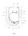
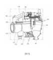
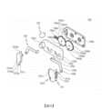
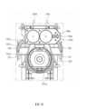
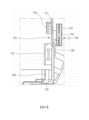
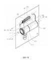
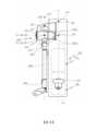
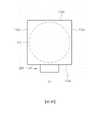
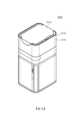
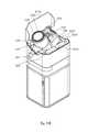
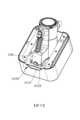
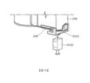
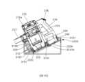
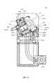
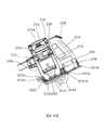
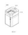
圖1是用於說明根據本發明一實施例之包含清掃機站、第一清掃機和第二清掃機的清掃機系統的立體圖。圖2是用於說明根據本發明實施例之清掃機系統的配置的示意圖。圖3是用於說明根據本發明實施例之清掃機系統的第一清掃機的視圖。圖4是用於說明根據本發明實施例之清掃機站的耦接部的視圖。圖5是用於說明在根據本發明實施例的清掃機站中固定元件、門元件、開蓋元件和拉桿元件的配置的視圖。圖6是用於說明根據本發明實施例之清掃機站的固定元件的分解立體圖。圖7是用於說明在根據本發明實施例的清掃機站中第一清掃機和固定元件的配置的視圖。圖8是用於說明根據本發明實施例之清掃機站的固定元件的剖面圖。圖8A是用於說明根據本發明另一實施例之固定元件的視圖。圖9是用於說明在根據本發明實施例的清掃機站中第一清掃機與門元件之間的關係的視圖。圖10是用於說明根據本發明實施例之第一清掃機的塵箱的下側的視圖。圖11是用於說明在根據本發明實施例的清掃機站中第一清掃機與開蓋元件之間的關係的視圖。圖12是用於說明根據本發明實施例之清掃機站的開蓋元件的立體圖。圖13是用於說明在根據本發明實施例的清掃機站中第一清掃機與拉桿元件之間的關係的視圖。圖13A是用於說明根據本發明另一實施例之拉桿元件的視圖。圖14是使用穿透第一清掃機之假想的平面用於說明在根據本發明實施例的清掃機系統中重量分佈的視圖。圖15是用於說明根據圖14另一實施例之假想的平面及假想的平面上的正交投影用於表示重量分佈的視圖 。圖16是使用假想線用於說明在根據本發明實施例的清掃機系統中於第一清掃機與清掃機站耦接的狀態下重量分佈的視圖。圖17A、圖17B是用於說明在第一清掃機以預定角度耦接於清掃機站的狀態下重量分佈的視圖。圖18是用於說明在第一清掃機以預定角度耦接於清掃機站的狀態下假想線與地面之間的角度以及假想線與至地面垂直線之間的角度的視圖。圖19是用於說明在根據本發明實施例的清掃機系統中第一清掃機和清掃機站耦接的狀態下用於保持平衡的配置的視圖。圖20是在另一方向上觀察圖19的示意圖。圖21是用於說明在根據本發明實施例的第一清掃機與清掃機站耦接的狀態下相對重的組件之間的配置關係的視圖。圖22和圖23是用於說明在根據本發明實施例的清掃機系統中使用者方便地將第一清掃機耦接到清掃機站的高度的視圖。圖24是用於說明根據本發第二實施例之包含清掃機站的清掃機系統的立體圖。圖25是用於說明根據本發第二實施例之包含清掃機站的清掃機系統的剖面圖。圖26是用於說明根據本發明第二實施例之清掃機站的立體圖。圖27是用於說明圖26中所示之第一門構件的狀態的立體圖。圖28和圖29是用於說明根據本發明第二實施例之第一清掃機的主體耦接於清掃機站的狀態的操作視圖。圖30是用於說明根據本發明第二實施例之清掃機站的耦接部的立體圖。圖31是用於說明根據本發明第二實施例之第一清掃機的主體耦接於清掃機站的耦接部的狀態的立體圖。圖32和圖33是用於說明根據本發明第二實施例之第一清掃機的主體固定到清掃機站的耦接部的狀態的操作視圖。圖34是用於說明根據本發明之第一清掃機的排放遮蓋開啟或關閉的狀態的視圖。圖35和圖36是用於說明根據本發明第二實施例之第一清掃機的主體耦接於清掃機站的耦接部的狀態的操作視圖。圖37是用於說明根據本發明第二實施例之清掃機系統的剖面圖。圖38和圖39是用於說明根據本發明之第一清掃機的壓縮構件的操作視圖。圖40至圖44是用於說明根據本發明其他實施例之清掃機系統的剖面圖。圖45和圖46是用於說明根據本發明第二實施例之第一清掃機的排放遮蓋開啟或關閉的狀態的視圖。圖47和圖48是根據本發明第二實施例之卷狀乙烯基薄膜接合於清掃機站中的狀態的操作視圖。圖49是用於說明根據本發明第二實施例之清掃機站的立體圖。圖50是用於說明根據本發明第二實施例之清掃機系統的立體圖。圖51是用於說明根據本發明第二實施例之清掃機站的一些組件的立體圖。圖52是用於說明根據本發明第二實施例之清掃機站的立體圖。圖53是用於說明根據本發明實施例之清掃機站的控制配置的區塊圖。圖54是用於說明根據本發明之控制清掃機站的方法的第一實施例的流程圖。圖55是用於說明根據本發明之控制清掃機站的方法的第二實施例的流程圖。圖56是用於說明根據本發明之控制清掃機站的方法的第三實施例的流程圖。圖57是用於說明根據本發明之控制清掃機站的方法的第四實施例的流程圖。FIG. 1 is a perspective view illustrating a sweeper system including a sweeper station, a first sweeper, and a second sweeper according to an embodiment of the present invention.FIG. 2 is a schematic diagram for explaining the configuration of a sweeper system according to an embodiment of the present invention.FIG. 3 is a view for explaining a first sweeper of the sweeper system according to an embodiment of the present invention.FIG. 4 is a view for explaining a coupling portion of a sweeper station according to an embodiment of the present invention.5 is a view for explaining the arrangement of a fixing member, a door member, a cover opening member, and a tie rod member in the sweeper station according to the embodiment of the present invention.FIG. 6 is an exploded perspective view illustrating a fixing element of a sweeper station according to an embodiment of the present invention.FIG. 7 is a view for explaining a configuration of a first sweeper and a fixing member in a sweeper station according to an embodiment of the present invention.Fig. 8 is a sectional view illustrating a fixing member of a sweeper station according to an embodiment of the present invention.FIG. 8A is a view for explaining a fixing member according to another embodiment of the present invention.FIG. 9 is a view for explaining a relationship between a first sweeper and a door member in a sweeper station according to an embodiment of the present invention.Fig. 10 is a view for explaining the lower side of the dust box of the first cleaning machine according to the embodiment of the present invention.FIG. 11 is a view for explaining a relationship between a first sweeper and a cover opening member in a sweeper station according to an embodiment of the present invention.FIG. 12 is a perspective view illustrating an opening element of the sweeper station according to an embodiment of the present invention.FIG. 13 is a view for explaining the relationship between the first sweeper and the tie rod member in the sweeper station according to the embodiment of the present invention.Fig. 13A is a view for explaining a tie rod member according to another embodiment of the present invention.FIG. 14 is a view for explaining weight distribution in the sweeper system according to the embodiment of the present invention using an imaginary plane penetrating the first sweeper.FIG. 15 is a view illustrating an imaginary plane and an orthogonal projection on the imaginary plane for representing weight distribution according to another embodiment of FIG. 14 .FIG. 16 is a view for explaining weight distribution in a state in which a first sweeper is coupled to a sweeper station in a sweeper system according to an embodiment of the present invention using phantom lines.17A, 17B are views for explaining weight distribution in a state where the first sweeper is coupled to the sweeper station at a predetermined angle.18 is a view for explaining an angle between an imaginary line and a ground and an angle between an imaginary line and a vertical line to the ground in a state where the first sweeper is coupled to the sweeper station at a predetermined angle.19 is a view for explaining a configuration for maintaining balance in a state where a first sweeper and a sweeper station are coupled in the sweeper system according to the embodiment of the present invention.FIG. 20 is a schematic view of FIG. 19 viewed from another direction.FIG. 21 is a view for explaining a configuration relationship among relatively heavy components in a state where a first sweeper and a sweeper station are coupled according to an embodiment of the present invention.22 and 23 are views for explaining a height at which a user conveniently couples a first sweeper to a sweeper station in a sweeper system according to an embodiment of the present invention.FIG. 24 is a perspective view illustrating a sweeper system including a sweeper station according to a second embodiment of the present invention.25 is a sectional view for explaining a sweeper system including a sweeper station according to a second embodiment of the present invention.Fig. 26 is a perspective view illustrating a sweeper station according to a second embodiment of the present invention.Fig. 27 is a perspective view for explaining the state of the first door member shown in Fig. 26 .28 and 29 are operational views for explaining a state in which a main body of a first sweeper is coupled to a sweeper station according to a second embodiment of the present invention.FIG. 30 is a perspective view illustrating a coupling portion of a sweeper station according to a second embodiment of the present invention.31 is a perspective view illustrating a state in which a main body of a first cleaning machine is coupled to a coupling portion of a cleaning machine station according to a second embodiment of the present invention.32 and 33 are operational views for explaining a state in which a main body of a first sweeper is fixed to a coupling portion of a sweeper station according to a second embodiment of the present invention.Fig. 34 is a view for explaining the state in which the discharge cover of the first sweeper according to the present invention is opened or closed.35 and 36 are operational views for explaining a state in which a main body of a first sweeper is coupled to a coupling portion of a sweeper station according to a second embodiment of the present invention.Fig. 37 is a sectional view for explaining a sweeper system according to a second embodiment of the present invention.38 and 39 are views for explaining the operation of the compressing member of the first sweeping machine according to the present invention.40 to 44 are cross-sectional views illustrating cleaning systems according to other embodiments of the present invention.45 and 46 are views for explaining the state of opening or closing the discharge cover of the first cleaning machine according to the second embodiment of the present invention.47 and 48 are operational views of a state in which a rolled vinyl film is joined in a sweeper station according to a second embodiment of the present invention.Fig. 49 is a perspective view illustrating a sweeper station according to a second embodiment of the present invention.Fig. 50 is a perspective view for explaining a cleaning machine system according to a second embodiment of the present invention.Fig. 51 is a perspective view illustrating some components of a sweeper station according to a second embodiment of the present invention.Fig. 52 is a perspective view illustrating a sweeper station according to a second embodiment of the present invention.FIG. 53 is a block diagram for explaining a control configuration of a sweeper station according to an embodiment of the present invention.Fig. 54 is a flowchart for explaining the first embodiment of the method of controlling the sweeper station according to the present invention.Fig. 55 is a flowchart for explaining the second embodiment of the method of controlling the sweeper station according to the present invention.Fig. 56 is a flowchart for explaining a third embodiment of a method of controlling a sweeper station according to the present invention.Fig. 57 is a flowchart for explaining a fourth embodiment of a method of controlling a sweeper station according to the present invention.
下面,將參照附圖詳細描述本發明的示例性實施例。Hereinafter, exemplary embodiments of the present invention will be described in detail with reference to the accompanying drawings.
本發明可以進行多種的修改以及具有多種的實施例,將在下文中具體描述附圖中示出的特定實施例。對實施例的描述並非旨在將本發明限制為特定實施例,而是應當理解為,本發明涵蓋落入本發明之精神和技術範圍內的所有修改、等同物和替代物。The present invention can be modified in various ways and has various embodiments, and specific embodiments shown in the drawings will be described in detail below. The description of the embodiments is not intended to limit the present invention to specific embodiments, but it should be understood that the present invention covers all modifications, equivalents and substitutions falling within the spirit and technical scope of the present invention.
本發明使用的術語僅用於描述特定的實施例,並不旨在限制本發明內容。單數表達可以包括複數表達,除非在上下文中明確描述為不同的含義。The terms used in the present invention are only used to describe specific embodiments, and are not intended to limit the content of the present invention. A singular expression may include a plural expression unless it is clearly described as a different meaning in context.
除非另有界定,本文使用的所有術語,包括技術或科學術語,具有本發明內容所涉及的技術領域的通常知識者共同理解的相同含義。諸如在常用詞典中定義的術語的含意可以理解為與相關技術上下文中的含義一致,除非在本發明中有明確定義,否則不能理解為理想或過於正式的含義。Unless otherwise defined, all terms used herein, including technical or scientific terms, have the same meaning as commonly understood by one of ordinary knowledge in the technical field to which this content of the invention belongs. The meanings of terms such as those defined in commonly used dictionaries can be understood as consistent with the meanings in the relevant technical context, and cannot be understood as ideal or overly formal meanings unless clearly defined in the present invention.
圖1是用於說明根據本發明一實施例之包含清掃機站、第一清掃機和第二清掃機的清掃機系統的立體圖;以及圖2是用於說明根據本發明實施例之清掃機系統的配置的示意圖。1 is a perspective view illustrating a sweeper system including a sweeper station, a first sweeper, and a second sweeper according to an embodiment of the present invention; and FIG. 2 is a perspective view illustrating a sweeper system according to an embodiment of the present invention A schematic diagram of the configuration.
參照圖1和圖2,根據本發明一實施例的清掃機系統10可以包括清掃機站100和清掃機200和300。在這種情況下,清掃機200和300可以包括第一清掃機200和第二清掃機300。同時,本實施例可以在不包括上述某些組件的情況下進行,也不排除附加組件。Referring to FIGS. 1 and 2 , a
清掃機系統10可以包括清掃機站100。第一清掃機200和第二清掃機300可以耦接於清掃機站100。第一清掃機200可以耦接至清掃機站100的側表面。具體來說,第一清掃機200的主體可以耦接於清掃機站100的側表面。第二清掃機200可以耦接於清掃機站100的下部。清掃機站100可以從第一清掃機200的塵箱220中清除灰塵。清掃機站100可以從第二清掃機300的塵箱(圖未顯示)中清除灰塵。
同時,圖3是用於說明在根據本發明實施例的除塵系統中第一清掃機的視圖;以及圖14是使用假想線和假想的平面用於說明根據本發明實施例之第一清掃機的重量分佈的視圖。Meanwhile, FIG. 3 is a view for explaining the first cleaning machine in the dust removal system according to an embodiment of the present invention; View of weight distribution.
首先,下面將參照圖1至圖3描述第一清掃機200的結構。First, the structure of the
第一清掃機200可以是指配置為由使用者手動操作的清掃機。例如,第一清掃機200可以是指手持式吸塵器或棒式吸塵器。The
第一清掃機200可以安裝在清掃機站100上。第一清掃機200可以由清掃機站100支撐。第一清掃機200可以耦接於清掃機站100。The
同時,在本發明的實施例中,可以基於塵箱220的底面(下表面)和電池殼體230的底面(下表面)放置在地面上的狀態來界定方向。Meanwhile, in the embodiment of the present invention, the direction may be defined based on a state where the bottom surface (lower surface) of the
在這種情況下,前向可以指基於抽吸馬達214設置抽吸部212的方向,而後向可以指設置把手216的方向。此外,基於從抽吸馬達214觀察抽吸部212的狀態,右向可以指組件設置在右邊的方向,而左向可以指組件設置在左邊的方向。此外,在本發明的實施例中,基於塵箱220的底面(下表面)和電池殼體230的底面(下表面)置於地面的狀態,在垂直於地面的方向上可以界定出上側和下側。In this case, the forward direction may refer to a direction in which the
第一清掃機200可以包括主體210。主體210可以包括主體殼體211、抽吸部212、灰塵分離部213、抽吸馬達214、排氣遮蓋215、把手216、以及操作部218。The
主體殼體211可以界定第一清掃機200的外觀。主體殼體211可以提供其中可以容納抽吸馬達214和過濾器(圖未顯示)的空間。主體殼體211可以形成為類似於圓柱形的形狀。The
抽吸部212可以從主體殼體211向外突出。例如,抽吸部212可以形成為具有敞開內部的圓柱形。抽吸部212可以耦接於延伸管250。抽吸部212可以稱為流動路徑(以下稱為'抽吸流動路徑'),含有灰塵的空氣可以通過該流動路徑流動。The
同時,在本實施例中,可以界定假想線,以穿透圓柱形的抽吸部212的內部。亦即,可以形成假想的抽吸流動路徑通過線a2,以在縱向上穿透抽吸流動路徑。Meanwhile, in the present embodiment, an imaginary line may be defined to penetrate the inside of the
在這種情況下,抽吸流動路徑通過線a2可以是形成為垂直於平面的假想線,並包括在該平面上的一點,其是藉由在徑向上和縱向(軸向)上切割抽吸部212而成。例如,抽吸流動路徑通過線a2可以是藉由連接圓的原點而成的假想線,其中圓的原點是藉由在徑向上和縱向(軸向)上切割圓柱形抽吸部212而成。In this case, the suction flow path passing line a2 may be an imaginary line formed perpendicular to the plane and including a point on the plane by cutting the suction flow in the radial direction and the longitudinal (axial) direction.
灰塵分離部213可以與抽吸部212連通。灰塵分離部213可以將透過抽吸部212引入灰塵分離部213中的灰塵分離出來。灰塵分離部213中的空間可以與塵箱220中的空間連通。The
例如,灰塵分離部213可以具有兩個或更多個旋風器部,能夠利用旋風流動來分離灰塵。此外,灰塵分離部213中的空間可以與抽吸流動路徑連通。因此,透過抽吸部212引入的空氣和灰塵沿著灰塵分離部213的內圓周表面螺旋地流動。因此,可以在灰塵分離部213的內部空間中產生旋風流動。For example, the
同時,在本實施例中,可以形成假想的旋風器線a4以在產生旋風流動的灰塵分離部213的向上/向下方向上延伸。Meanwhile, in the present embodiment, an imaginary cyclone line a4 may be formed to extend in the upward/downward direction of the
在這種情況下,旋風器線a4可以是形成為垂直於平面的假想線並包括在該平面上的一點,其藉由在徑向方向上切割灰塵分離部213而成。In this case, the cyclone line a4 may be an imaginary line formed perpendicular to a plane and including a point on the plane by cutting the
抽吸馬達214可以產生用於抽吸空氣的抽吸力。抽吸馬達214可以容納在主體殼體211中。抽吸馬達214可以藉由旋轉的方式產生抽吸力。例如,抽吸馬達214可以形成為類似於圓柱形的形狀。The
同時,在本實施例中,可以藉由延伸抽吸馬達214的旋轉軸來形成假想的抽吸馬達軸線a1。Meanwhile, in the present embodiment, an imaginary suction motor axis a1 may be formed by extending the rotation shaft of the
排氣遮蓋215可以設置在主體殼體211的軸向的一側。用於過濾空氣的過濾器可以容納在排氣遮蓋215中。例如,HEPA過濾器可以容納在排氣遮蓋215中。The
排氣遮蓋215可以具有排氣口215a,用於排放由抽吸馬達214的抽吸力所引入的空氣。The
流動導引件可以設置在排氣遮蓋215上。流動導引件可以導引通過排氣口215a排出的氣流。Flow guides may be provided on the
把手216可以由使用者握持。把手216可以設置在抽吸馬達214的後側。例如,把手216可以形成為類似於圓柱形的形狀。可選地,把手216可以形成為彎曲的圓柱形。把手216可以相對於主體殼體211、抽吸馬達214或灰塵分離部213設置在預定角度處。The
把手216可以包括形成為柱狀的握持部216a,以便使用者可以抓住握持部216a、第一延伸部216b以及第二延伸部216c,第一延伸部216b連接到握持部216a的縱向(軸向)上的一端並朝抽吸馬達214延伸,第二延伸部216c連接到握持部216a的縱向(軸向)上的另一端並朝塵箱220延伸。The
同時,在本實施例中,可以形成假想的握持部通過線a3,以在握持部216a的縱向上(圓柱的軸向)延伸,並穿透握持部216a。Meanwhile, in the present embodiment, an imaginary grip passing line a3 may be formed to extend in the longitudinal direction of the
例如,握持部通過線a3可以是形成在圓柱形的把手216中的假想線,即平行於握持部216a的外表面(外圓周表面)的至少一部分而形成的假想線。For example, the grip passing line a3 may be an imaginary line formed in the
把手216的上表面可以界定第一清掃機200上表面的一部分的外觀。因此,當使用者握住把手216時可以防止第一清掃機200的組件接觸使用者的臂部。The upper surface of the
第一延伸部216b可以從握持部216a朝主體殼體211或抽吸馬達214延伸。第一延伸部216b的至少一部分可以在水平方向上延伸。The
第二延伸部216c可以從握持部216a朝塵箱220延伸。第二延伸部216c的至少一部分可以在水平方向上延伸。The
操作部218可以設置在把手216上。操作部218可以設置在形成在把手216的上部區域中的傾斜表面上。使用者可以透過操作部218輸入操作或停止第一清掃機200的指令。The
第一清掃機200可以包括塵箱220。塵箱220可以與灰塵分離部213連通。塵箱220可以儲存由灰塵分離部213分離的灰塵。The
塵箱220可以包括塵箱主體221、排放遮蓋222、塵箱壓縮桿223、以及壓縮構件224。The
塵箱主體221可以提供能夠儲存從灰塵分離部213分離的灰塵的空間。例如,塵箱主體221可以形成為類似於圓柱形的形狀。The dust box
同時,在本實施例中,可以形成假想的塵箱通過線a5,以穿透塵箱主體221內部(內部空間),並在塵箱主體221的縱向(即圓柱形塵箱主體221的軸向)上延伸。At the same time, in this embodiment, an imaginary dust box passage line a5 can be formed to penetrate the interior (inner space) of the dust box
在這種情況下,塵箱通過線a5可以是形成為垂直於平面的假想線,並包括在該平面上的一點,其藉由在徑向上和縱向(圓柱形塵箱主體221的軸向)上切割塵箱220而成。In this case, the dust box passing line a5 may be an imaginary line formed perpendicular to the plane and including a point on the plane by passing the line a5 in the radial direction and the longitudinal direction (the axial direction of the cylindrical dust box main body 221) Upper cutting
例如,塵箱通過線a5可以是形成為垂直於圓的假想線,並通過該圓的原點,其藉由在徑向上和縱向上切割塵箱220而成。For example, the dust box passing line a5 may be an imaginary line formed perpendicular to a circle and passing through the origin of the circle, which is formed by cutting the
塵箱主體221下側(底側)的一部分可以開口。此外,下延伸部221a可以形成在塵箱主體221的下側(底側)。下延伸部221a可以形成以擋住塵箱主體221下側的一部分。A part of the lower side (bottom side) of the dust box
塵箱220可以包括排放遮蓋222。排放遮蓋222可以設置在塵箱220的下側。排放遮蓋222可以選擇性地開啟或關閉向下開口的塵箱220的下側。The
排放遮蓋222可以包括遮蓋主體222a和鉸鏈部222b。遮蓋主體222a可以形成以擋住塵箱主體221下側的一部分。遮蓋主體222a可以圍繞鉸鏈部222b向下旋轉。鉸鏈部222b可以設置相鄰於電池殼體230。排放遮蓋222可以藉由鉤子嚙合耦接到塵箱220。The
同時,塵箱220可以進一步包括耦接桿222c。排放遮蓋222可以藉由耦接桿222c從塵箱220分離。耦接桿222c可以設置在塵箱的前側。具體而言,耦接桿222c可以設置在塵箱220的前側的外表面上。當外力作用於耦接桿222c時,耦接桿222c可以使從遮蓋主體222a延伸的鉤子彈性變形,以釋放遮蓋主體222a與塵箱主體221之間的鉤子嚙合。Meanwhile, the
當排放遮蓋222關閉時,可以藉由排放遮蓋222和下延伸部221a擋住(密封)塵箱220的下側。When the
塵箱220可以進一步包括塵箱壓縮桿223和壓縮構件224。The
同時,根據本實施例的第一清掃機200具有塵箱壓縮桿223和壓縮構件224,但塵箱壓縮桿223和壓縮構件224並非必要。根據實施例,第一清掃機200可以配置成不具有塵箱壓縮桿223和壓縮構件224。Meanwhile, the
塵箱壓縮桿223可以設置在塵箱220或灰塵分離部213的外部。塵箱壓縮桿223可以設置在塵箱220或灰塵分離部213的外部,以便可向上和向下移動。塵箱壓縮桿223可以連接於壓縮構件224。當塵箱壓縮桿223透過外力向下移動時,壓縮構件224也可以向下移動。因此,可以為使用者提供便利性。壓縮構件224和塵箱壓縮桿223可以藉由彈性構件(圖未顯示)返回到原始位置。具體來說,當施加在塵箱壓縮桿223上的外力被消除時,彈性構件可以將塵箱壓縮桿223和壓縮構件224向上移動。The dust
壓縮構件224可以設置在塵箱主體221中。壓縮構件224可以在塵箱主體221的內部空間中移動。具體來說,壓縮構件224可以在塵箱主體221中向上和向下移動。因此,壓縮構件224可以壓縮塵箱主體221中的灰塵。此外,當排放遮蓋222與塵箱主體221分離,進而開啟塵箱220的下側時,壓縮構件224可以從塵箱220的上側移動到塵箱220的下側,以清除塵箱220中的異物,諸如殘留的灰塵。因此,可以藉由防止殘留的灰塵留在塵箱220中來提高清掃機的抽吸力。此外,可以藉由防止殘留的灰塵留在塵箱220中,來去除由於殘留的灰塵所引起的異味(見圖38和圖39)。A
第一清掃機200可以包括電池殼體230。電池240可以容納在電池殼體230中。電池殼體230可以設置在把手216的下側。例如,電池殼體230可以具有在其下側開口的六面體形狀。電池殼體230的後表面可以連接於把手216。The
電池殼體230可以包括在其下側開口的容納部。可以透過電池殼體220的容納部安裝或拆卸電池240。The
第一清掃機200可以包括電池240。The
例如,電池240可以可拆卸地耦接於第一清掃機200。電池240可以可拆卸地耦接於電池殼體230。例如,可以從電池殼體230的下側將電池240插入電池殼體230中。上述配置可以提高第一清掃機200的便攜性。For example, the
除此以外,電池240可以一體地設置在電池殼體230中。在這種情況下,電池240的下表面不會曝露於外部。Besides, the
電池240可以向第一清掃機200的抽吸馬達214供電。電池240可以設置在把手216的下部上。電池240可以設置在塵箱220的後側。亦即,抽吸馬達214和電池240可以設置成在向上/向下方向上不相互重疊,並設置在不同的設置高度上。基於把手216,重量較大的抽吸馬達214設置在把手216的前側,而重量較大的電池240設置在把手216的下側,如此第一清掃機200的整體重量可以均勻地分布。因此,當使用者抓住把手216並進行清掃操作時,可以防止對使用者的手腕施加壓力。The
根據本實施例,在電池240耦接於電池殼體230的情況下,電池240的下表面可以曝露於外部。因為當第一清掃機200放置在地板上時,電池240可以放置在地板上,可以立即從電池殼體230拆卸電池240。此外,由於電池240的下表面曝露於外部,因此直接接觸電池240外面的空氣,可改善電池240的冷卻性能。According to the present embodiment, when the
同時,在電池240一體地固定在電池殼體230上的情況下,可以減少用於安裝或拆卸電池240和電池殼體230的結構數量,因此,可以減少第一清掃機200的整體尺寸和第一清掃機200的重量。At the same time, under the condition that the
第一清掃機200可以包括延伸管250。延伸管250可以與清掃模組260連通。延伸管250可以與主體210連通。延伸管250可以與主體210的抽吸部214連通。延伸管250可以形成為長圓柱形。The
主體210可以連接於延伸管250。主體210可以透過延伸管250連接於清掃模組260。主體210可以藉由抽吸馬達214產生抽吸力,並透過延伸管250向清掃模組260提供抽吸力。外面的灰塵可以透過清掃模組260和延伸管250引入主體210中。The
第一清掃機200可以包括清掃模組260。清掃模組260可以與延伸管250連通。清掃模組260可以與延伸管250 連通。因此,外部空氣可以藉由第一清掃機200的主體210中的抽吸力,經由清掃模組260和延伸管250引入第一清掃機200的主體210中。The
可以藉由清掃機站100的集塵部170透過重力和集塵馬達191的抽吸力擷取第一清掃機200的塵箱220中的灰塵。因此,可以在不需要使用者額外操作的情況下清除塵箱中的灰塵,從而為使用者提供便利性。此外,可以消除由於使用者需要頻繁清空塵箱而造成的不便。此外,還可以防止在清空塵箱時灰塵飛散。The dust in the
第一清掃機200可以耦接於殼體110的側表面。具體而言,第一清掃機200的主體210可以安裝在耦接部120上。更具體地說,第一清掃機200的塵箱220和電池殼體230可以耦接到耦接表面121,塵箱主體221的外圓周表面可以耦接到塵箱導引表面122,並且抽吸部212可以耦接到耦接部120的抽吸部導引表面126。在這種情況下,塵箱220的中心軸可以設置在與地面平行的方向上,而且延伸管250可以設置在垂直於地面的方向上(見圖2)。The
清掃機系統10可以包括第二清掃機300。第二清掃機300可以是指清掃機器人。第二清掃機300可以在自動地於待清掃區域行進時,藉由從地板抽吸諸如灰塵的異物來自動地在待清掃區域內進行清掃。第二清掃機300、即清掃機器人、可以包括距離感測器,配置以偵測:與諸如安裝在待清掃區內的傢俱、辦公用品或牆壁的障礙物的距離、以及用於移動清掃機器人的左滾輪和右滾輪。第二清掃機300可以耦接於清掃機站100。可以透過第二清掃機流動路徑部分182將第二清掃機300中的灰塵擷取到集塵部170中。The
同時,圖19和圖20是用於說明根據本發明實施例之清掃機系統中第一清掃機與清掃機站耦接的狀態以及根據第一清掃機與清掃機站之間的耦接用於保持平衡的視圖。At the same time, Fig. 19 and Fig. 20 are used to explain the coupling state of the first sweeper and the sweeper station in the sweeper system according to the embodiment of the present invention and the coupling between the first sweeper and the sweeper station for Keep a balanced view.
下面將參照圖1、圖2、圖19和圖20描述根據本發明的清掃機站100。A
第一清掃機200和第二清掃機300可以設置在清掃機站100上。第一清掃機200可以耦接於清掃站100的側表面。具體而言,第一清掃機200的塵箱220可以耦接於清掃機站100的側表面。第二清掃機200可以耦接於清掃機站100的下部。清掃機站100可以從第一清掃機200的塵箱220去除灰塵。清掃機站100可以從第二清掃機300的塵箱(圖未顯示)去除灰塵。The
清掃機站100可以包括殼體110。殼體110可以界定清掃機站100的外觀。具體而言,殼體110可以形成為包含一個或多個外壁表面的柱子形式。例如,殼體110可以形成為類似於四角柱的形狀。
殼體110可以具有能夠容納集塵部170的空間,集塵部170配置以儲存灰塵於其中;以及吸塵模組190,配置以產生用於從集塵部170收集灰塵的流動力。The
殼體110可以包括底表面111和外壁表面112。The
底表面111可以支撐吸塵模組190的重力方向上的下側。亦即,底表面111可以支撐吸塵模組190的集塵馬達191的下側。The
在這種情況下,可以朝著地面設置底表面111。底表面111也可以設置平行於地面,或者設置為相對於地面以預定角度傾斜。即使在耦接第一清掃機200的情況下,上述配置也可以有利於穩定地支撐集塵馬達191並保持整體重量的平衡。In this case, the
同時,根據實施例,底表面111可以進一步包括地面支撐部(圖未顯示),以防止清掃機站100傾倒,並增加與地面接觸的面積以保持平衡。例如,該地面支撐部可以具有從底表面111延伸的板狀形狀,並且一個或多個框架可以在地面方向上從底表面111突出和延伸。在這種情況下,該地面支撐部可以設置為線性對稱,以便基於其上安裝有第一清掃機200的前表面保持左右平衡和前後平衡。Meanwhile, according to an embodiment, the
外壁表面112可以指在重力方向上形成的表面或是與底表面111相連的表面。例如,外壁表面112可以指連接至底表面111以垂直於底表面111的表面。另一實施例,外壁表面112可以設置為相對於底表面111以預定角度傾斜。The outer wall surface 112 may refer to a surface formed in a gravity direction or a surface connected to the
外壁表面112可以包括至少一個表面。例如,外壁表面112可以包括第一外壁表面112a、第二外壁表面112b、第三外壁表面112c、以及第四外壁表面112d。The outer wall surface 112 may include at least one surface. For example, the outer wall surface 112 may include a first
在這種情況下,在本實施例中,第一外壁表面112a可以設置在清掃機站100的前表面上。在這種情況下,該前表面可以指其上耦接有第一清掃機200或第二清掃機300的表面。因此,第一外壁表面112a可以界定清掃機站100的前表面的外觀。In this case, in the present embodiment, the first
同時,為了理解本實施例,將方向界定如下。在本實施例中,可以在第一清掃機200安裝於清掃機站100上的狀態下界定方向。Meanwhile, in order to understand the present embodiment, the directions are defined as follows. In this embodiment, the direction may be defined in a state where the
在這種情況下,包含抽吸部212的延伸線212a的表面可以稱為前表面(見圖1)。亦即,在第一清掃機200安裝於清掃機站100上的狀態下,抽吸部212的一部分可以接觸並耦接於抽吸部導引表面126,而抽吸部212的剩餘部分,即不與抽吸部導引表面126耦接的部分,可以設置為曝露在第一外壁表面112a的外部。因此,抽吸部212之假想的延伸線212a可以設置在第一外壁表面112a上,且包含抽吸部212的延伸線212a的表面可以稱為前表面。In this case, a surface including the
從另一觀點看,在拉桿臂161耦接於殼體110的狀態下,包含將拉桿臂161曝露於外部的一側的表面可以稱為前表面。From another point of view, in a state where the
從又一觀點看,在第一清掃機200安裝在清掃機站100上的狀態下,被第一清掃機的主體210穿透的清掃機站100的外表面可以稱為前表面。From yet another point of view, in a state where the
此外,在第一清掃機200安裝在清掃機站100上的狀態下,第一清掃機200曝露於清掃機站100外部的方向可以稱為向前方向。In addition, in a state where the
此外,從另一觀點看,在第一清掃機200安裝在清掃機站100上的狀態下,設置第一清掃機200的抽吸馬達214的方向可以稱為向前方向。此外,相反於抽吸馬達214設置在清掃機站100上的方向可以稱為向後方向。Also, from another point of view, the direction in which the
從再一觀點看,以清掃機站100為基準,在握持部通過線a3與抽吸馬達軸線a1相交的交會點所設置的方向可以稱為向前方向。或者,在握持部通過線a3與抽吸流動路徑通過線a2相交的交會點P2所設置的方向可以稱為向前方向。或者,在抽吸馬達軸線a1與抽吸流動路徑通過線a2相交的交會點P1所設置的方向可以稱為向前方向。此外,以清掃機站100為基準,相反於設置交會點的方向的方向可以稱為向後方向。From yet another point of view, with the
此外,以殼體110的內部空間為基準,面向前表面的表面可以稱為清掃機站100的後表面。因此,該後表面可以指第二外壁表面112b形成的方向。Also, the surface facing the front surface may be referred to as a rear surface of the
進一步說,以殼體110的內部空間為基準,在觀看前表面時的左表面可以稱為左表面,而在觀看前表面時的右表面可以稱為右表面。因此,該左表面可以指形成第三外壁表面112c的方向,而右表面可以指形成第四外壁表面112d的方向。Furthermore, based on the internal space of the
第一外壁表面112a可以形成為平面的形式,或者第一外壁表面112a可以整體形成為曲面的形式,或者形成以部分包含曲面。The first
第一外壁表面112a可以具有與第一清掃機200的形狀相對應的外觀。詳細地說,耦接部120可以設置在第一外壁表面112a中。藉由這種配置,第一清掃機200可以耦接於清掃機站100並由清掃機站100支撐。耦接部120的具體配置將在下面描述。The first
根據本實施例,拉桿元件160可以設置在第一外壁表面112a上。具體而言,拉桿元件160的拉桿臂161可以安裝在第一外壁表面112a上。例如,第一外壁表面112a可以具有臂部容納槽,其中可以容納拉桿臂161。在這種情況下,該臂部容納槽可以形成以與拉桿臂161的形狀相對應。因此,當拉桿臂161安裝在臂部容納槽中時,第一外壁表面112a和拉桿臂161的外表面可以界定一連續外部形狀,並且拉桿臂161可以藉由拉桿元件160的操作而被行程地移動以從第一外壁表面112a突出。According to the present embodiment, the
同時,用於安裝第一清掃機200所用之各種類型的清掃模組260的結構可以額外地設置在第一外壁表面112a上。Meanwhile, structures for installing various types of cleaning
此外,可耦接第二清掃機300的結構可以額外地設置在第一外壁表面112a上。因此,對應於第二清掃機300的形狀的結構可以額外地設置在第一外壁表面112a上。In addition, a structure to which the
此外,可與第二清掃機300的下表面耦接的清掃機底板(圖未顯示)可以額外耦接於第一外壁表面112a。同時,作為另一實施例,清掃機底板(圖未顯示)可以被塑造成連接於底表面111。In addition, a sweeper floor (not shown) that can be coupled to the lower surface of the
在本實施例中,第二外壁表面112b可以是面對第一外壁表面112a的表面。亦即,第二外壁表面112b可以設置在清掃機站100的後表面上。在這種情況下,該後表面可以是面對第一清掃機200或第二清掃機300所耦接的表面。因此,第二外壁表面112b可以界定清掃機站100後表面的外觀。In this embodiment, the second
例如,第二外壁表面112b可以形成為平面的形式。藉由這種配置,清掃機站100可以與空間內壁緊密接觸,並可以穩定支撐清掃機站100。For example, the second
作為另一個示例,用於安裝第一清掃機200所用之各種類型的清掃模組260的結構可以額外地設置在第二外壁表面112b上。As another example, structures for installing various types of cleaning
此外,可耦接於第二清掃機300的結構可以額外地設置第二外壁表面112b上。因此,對應於第二清掃機300的形狀的結構可以額外地設置在第二外壁表面112b上。In addition, a structure coupleable to the
此外,可與第二清掃機300的下表面耦接的清掃機底板(圖未顯示)可以額外地耦接於第二外壁表面112b。同時,作為另一實施例,清掃機底板(圖未顯示)可以被塑造成連接於底表面111。藉由這種配置,當第二清掃機300耦接於清掃機底板(圖未顯示)時,可以降低清掃機站100的整體重心,從而可以穩定地支撐清掃機站100。In addition, a sweeper floor (not shown) that may be coupled to the lower surface of the
在本實施例中,第三外壁表面112c和第四外壁表面112d可以指連接於第一外壁表面112a和第二外壁表面112b的表面。在這種情況下,第三外壁表面112c可以設置在清掃機站100的左表面上,而第四外壁表面112d可以設置在清掃機站100的右表面上。除此以外,第三外壁表面112c可以設置在清掃機站100的右表面上,而第四外壁表面112d可以設置在清掃機站100的左表面上。In this embodiment, the third
第三外壁表面112c或第四外壁表面112d可以形成為平面的形式,或者第三外壁表面112c或第四外壁表面112d可以整體形成為曲面的形式,或者形成以部分地包含曲面。The third
同時,用於安裝第一清掃機200之各類清掃模組260的結構可以額外地設置在第三外壁表面112c或第四外壁表面112d上。Meanwhile, structures for installing various types of cleaning
此外,可耦接於第二清掃機300的結構可以額外地設置在第三外壁表面112c或第四外壁表面112d上。因此,對應於第二清掃機300的形狀的結構可以額外地設置在第三外壁表面112c或第四外壁表面112d上。In addition, a structure coupleable to the
此外,可耦接於第二清掃機300下表面的清掃機底板(圖未顯示)可以額外地設置在第三外壁表面112c或第四外壁表面112d上。同時,作為另一實施例,清掃機底板(圖未顯示)可以被塑造成連接於底表面111。In addition, a sweeper floor (not shown) that can be coupled to the lower surface of the
圖4是用於說明根據本發明實施例之清掃機站的耦接部的視圖;以及圖5是用於說明在根據本發明實施例的清掃機站中固定元件、門元件、開蓋元件以及拉桿元件的配置的視圖。Fig. 4 is the view for explaining the coupling portion of the cleaning machine station according to the embodiment of the present invention; View of the configuration of tie rod elements.
下面將參照圖4和圖5描述根據本發明的清掃機站100的耦接部120。The
清掃機站100可以包括耦接部120,第一清掃機200耦接到該耦接部。具體而言,耦接部120可以設置在第一外壁表面112a中,並且第一清掃機200的主體210、塵箱220和電池殼體230可以耦接到耦接部120。The
耦接部120可以包括耦接表面121。耦接表面121可以設置在殼體110的側表面上。例如,耦接表面121可以是指形成為凹槽形式的表面,該凹槽從第一外壁表面112a朝清掃機站100的內部凹陷。亦即,耦接表面121可以是指相對於第一外壁表面112a形成已具有階梯部的表面。The
第一清掃機200可以耦接於耦接表面121。例如,耦接表面121可以與第一清掃機200的塵箱220的下表面和電池殼體230的下表面接觸於。在這種情況下,下表面可以指當使用者使用第一清掃機200或將第一清掃機200放在地面上時指向地面的表面。The
在這種情況下,第一清掃機200的耦接表面121與塵箱220之間的耦接可以意味著實體的耦接,藉由這種耦接,第一清掃機200與清掃機站100彼此耦合和固定。這可以是流動路徑耦接的前提,通過該流動路徑,塵箱220和流動路徑部分180彼此連通且流體可以流過該流動路徑。In this case, the coupling between the
此外,第一清掃機200的耦接表面121與電池殼體230之間的耦接可以是指實體的耦接,藉由這種耦接,第一清掃機200與清掃機站100彼此耦合和固定。這可以是電性耦接的前提,電池240和充電部128可以藉由該電性耦接而彼此電性連接。In addition, the coupling between the
例如,耦接表面121相對於地面的角度可以是直角。因此,當第一清掃機200耦接於耦接表面121時,可以最小化清掃機站100的空間。For example, the angle of the
作為另一個示例,耦接表面121可以設置為相對於地面以預定角度傾斜。因此,當第一清掃機200耦接於耦接表面121時,可以穩定支撐清掃機站100。在這種情況下,耦接表面121相對於地面的角度可以設置為40度或更大及95度或更小。特別是,耦接表面121相對於地面的角度可以設置為43度或更大及90度或更小。如果耦接表面121相對於地面的角度設置為小於40度,使用者需要彎腰才能將第一清掃機200耦接於清掃機站100,這可能會讓使用者感到不適。如果耦接表面121相對於地面的角度設置為大於95度,則第一清掃機200可以會因其自身重量而與清掃機站100分離。As another example, the
耦接表面121可以具有灰塵通孔121a,殼體110外部的空氣可以通過灰塵通孔121a引入殼體110中。灰塵通孔121a可以形成為孔的形式,對應於塵箱220的形狀,使得塵箱220中的灰塵可以引入集塵部170中。灰塵通孔121a可以形成為對應於塵箱220的排放遮蓋222的形狀。灰塵通孔121a可以形成以與將在下面描述的第一清掃機流動路徑部分181連通。The
耦接部120可以包括塵箱導引表面122。塵箱導引表面122可以設置在第一外壁表面112a上。塵箱導引表面122可以連接至第一外壁表面112a。此外,塵箱導引表面122可以連接至耦接表面121。The
塵箱導引表面122可以形成為對應於塵箱220的外表面的形狀。塵箱220的前外表面可以耦接到塵箱導引表面122。因此,當將第一清掃機200耦接到耦接表面121時,可以提供便利性。The dust
耦接部120可以包括導引突出部123。導引突出部123可以設置在耦接表面121上。導引突出部123可以從耦接表面121向上突出。兩個導引突出部123可以設置為彼此間隔開。彼此間隔開的兩個導引突出部123之間的距離可以對應於第一清掃機200的電池殼體230的寬度。因此,當將第一清掃機200耦接到耦接表面121時,可以提供便利性。The
耦接部120可以包括側壁124。側壁124可以指設置在耦接表面121的兩個側面上的壁表面,並可以垂直地連接於耦接表面121。側壁124可以連接於第一外壁表面112a。此外,側壁124可以連接於塵箱導引表面122。亦即,側壁124可以界定連接於塵箱導引表面122的表面。因此,可以穩定地容納第一清掃機200。The
耦接部120可以包括耦接感測器125。耦接感測器125可以檢測第一清掃機200是否實體地耦接到耦接部120。The
耦接感測器125可以包括接觸感測器。例如,耦接感測器125可以包括微型開關。在這種情況下,耦接感測器125可以設置在導引突出部123上。因此,當第一清掃機200的電池殼體230或電池240耦接於一對導引突出部123之間時,電池殼體230或電池240接觸於耦接感測器125,如此耦接感測器125可以檢測第一清掃機200實體耦接於清掃機站100。The
同時,耦接感測器125可以包括非接觸感測器。例如,耦接感測器125可以包括紅外線(IR)感測器。在這種情況下,耦接感測器125可以設置在側壁124上。因此,當第一清掃機200的塵箱220或主體210通過側壁124然後到達耦接表面121時,耦接感測器125可以檢測塵箱220或主體210的存在,並檢測第一清掃機200實體耦接於清掃機站100。Meanwhile, the
耦接感測器125可以面對第一清掃機200的塵箱220或電池殼體230。The
耦接感測器125可以是用於確定第一清掃機200是否耦接以及是否有施加電力到第一清掃機200的電池240的裝置。The
耦接部120可以包括抽吸部導引表面126。抽吸部導引表面126可以設置在第一外壁表面112a上。抽吸部導引表面126可以連接於塵箱導引表面122。抽吸部212可以耦接於抽吸部導引表面126。抽吸部導引表面126的形狀可以對應於抽吸部212的形狀。因此,當將第一清掃機200的主體210耦接於耦接表面121時,可以提供便利性。The
耦接部120可以包括固定構件進入孔127。固定構件進入孔127可以形成為沿側壁124的長孔,使得固定構件131可以進入和離開固定構件進入孔127。例如,固定構件進入孔127可以是沿側壁124所形成的矩形孔。將在下文中詳細描述固定構件131。The
藉由這種配置,當使用者將第一清掃機200耦接於清掃機站100的耦接部120時,第一清掃機200的主體210可以藉由塵箱導引表面122、導引突出部123和抽吸部導引表面126穩定地設置在耦接部120上。因此,當將第一清掃機200的塵箱220和電池殼體230耦接到耦接表面121時,可以提供便利性。With this configuration, when the user couples the
同時,圖6至圖8是用於說明根據本發明實施例之清掃機站的固定元件的視圖。Meanwhile, FIGS. 6 to 8 are views for explaining fixing elements of a sweeper station according to an embodiment of the present invention.
下面將參照圖4至圖8描述根據本發明的固定元件130。The fixing
根據本發明的清掃機站100可以包括固定元件130。固定元件130可以設置在側壁124上。此外,固定元件130可以設置在耦接表面121的背面上。固定元件130可以固定耦接到耦接表面121的第一清掃機200。具體而言,固定元件130可以將第一清掃機200的塵箱220和電池殼體230固定到耦接表面121。The
固定元件130可以包括固定構件131,配置以固定第一清掃機200的塵箱220和電池殼體230;以及固定驅動部133,配置以操作固定構件131。此外,固定元件130可以進一步包括固定部齒輪134,配置以將動力從固定驅動部133傳遞到固定構件131;以及固定部連桿135,配置以將固定部齒輪134的旋轉運動轉換為固定構件131的往復運動。此外,固定元件130還可以包括固定部殼體132,配置以容納固定驅動部133和固定部齒輪134。The fixing
固定構件131可以設置在耦接部120的側壁124上,並設置在側壁124上,以便進行往復運動以固定塵箱220。具體來說,固定構件131可以容納在固定構件進入孔127中。The fixing
固定構件131可以分別設置在耦接部120的兩側。例如,一對兩個固定構件131可以相對於耦接表面121對稱地設置。The fixing
具體來說,固定構件131可以包括連桿耦接部131a、可動面板131b、以及可動密封件131c。在這種情況下,連桿耦接部131a可以設置在可動面板131b的一側,而可動密封件131c可以配置在可動面板131b的另一側。Specifically, the fixed
連桿耦接部131a設置在可動面板131b的一側,並耦接於固定部連桿135。例如,連桿耦接部131a以圓柱形或圓銷狀從連接突出部131bb突出,該連接突出部131bb藉由彎曲和延伸可動面板131b的一端來形成。因此,連桿耦接部131a可以可旋轉地插入並耦接於固定部連桿135的一端。The
可動面板131b可以連接於連桿耦接部131a,並設置以藉由操作固定驅動部133從側壁124朝塵箱220往復移動。例如,可動面板131b可以設置以可沿導引框架131d直線和往復移動。The
具體而言,可動面板131b的一側可以設置以容納在第一外壁表面112a中的空間內,而可動面板131b的另一側可以設置以從側壁124露出。Specifically, one side of the
可動面板131b可以包括面板主體131ba、連接突出部131bb、第一按壓部131bc、以及第二按壓部131bd。例如,面板主體131ba可以形成為平板的形式。此外,連接突出部131bb可以設置在面板主體131ba的一端。此外,第一按壓部131bc可以形成在面板主體131ba的另一端。The
可以藉由將面板主體131ba的一端朝固定驅動部133彎曲和延伸來形成連接突出部131bb。連桿耦接部131a可以從連接突出部131bb的頂端突出和延伸。The connection protrusion 131bb may be formed by bending and extending one end of the panel main body 131ba toward the fixed driving
連接突出部131bb可以具有框架通孔,其可以由導引框架131d穿透。例如,該框架通孔可以形成為類似於 "I "形的形狀。The connection protrusion 131bb may have a frame through hole, which may be penetrated by the
第一按壓部131bc形成在面板主體131ba的另一端,並形成為對應於塵箱220的形狀的形狀,以便密封塵箱220。例如,第一按壓部131bc可以形成為能夠圍繞圓柱形的形狀。亦即,第一按壓部131bc可以指具有凹弧形並形成在面板主體131ba的另一側的端部。The first pressing part 131bc is formed at the other end of the panel body 131ba, and is formed in a shape corresponding to the shape of the
第二按壓部131bd可以連接於第一按壓部131bc,並形成為對應於電池殼體230的形狀的形狀,以便密封電池殼體230。例如,第二按壓部131bd可以形成為能夠按壓電池殼體230的形狀。亦即,第二按壓部131bd可以指具有直線形狀並形成在面板主體131ba另一側的端部。The second pressing part 131bd may be connected to the first pressing part 131bc and formed in a shape corresponding to the shape of the
可動密封件131c可以設置在可動面板131b的往復方向上的頂端上,並可以密封塵箱220。具體而言,可動密封件131c可以耦接於第一按壓部131bc,並可以在第一按壓部131bc圍繞和按壓塵箱220時,密封塵箱220與第一按壓部131bc之間的空間。此外,可動密封件131c可以耦接於第二按壓部131bd,並可以在第二按壓部131bd圍繞和按壓電池殼體230時,密封電池殼體230與第二按壓部131bd之間的空間。The
固定元件130可以進一步包括導引框架131d,耦接於殼體110並設置以穿透可動面板131b並導引固定構件131的運動。例如,導引框架131d可以是具有"I "形的框架,其穿透連接突出部131bb。藉由這種配置,可動面板131b可以沿著導引框架131d直線地往復運動。The fixing
固定部殼體132可以設置在殼體110中。例如,固定部殼體132可以設置在耦接表面121的背面上。The fixing
固定部殼體132可以在其中具有能夠容納固定部齒輪134的空間。此外,固定部殼體132可以容納固定驅動部133。The
固定部殼體132可以包括第一固定部殼體132a、第二固定部殼體132b、連桿導孔132c、以及馬達容納部132d。The fixing
第一固定部殼體132a和第二固定部殼體132b彼此耦接,以界定能夠在其中容納固定部齒輪134的空間。The first
例如,第一固定部殼體132a可以在朝清掃機站100的外部方向上設置,而第二固定部殼體132b可以在朝清掃機站100的內部方向上設置。亦即,第一固定部殼體132a可以在朝耦接表面121的方向上設置,而第二固定部殼體132b可以在朝第二外壁表面112b的方向上設置。For example, the first
連桿導孔132c可以形成在第一固定部殼體132a中。連桿導孔132c可以指形成以導引固定部連桿135的移動路線的孔。例如,連桿導孔132c可以指在圍繞固定部齒輪134的旋轉軸的圓周方向上所形成的弧形孔。A
兩個連桿導孔132c可以形成以導引一對固定部連桿135,用於移動該對固定構件132。此外,可以對稱地形成兩個連桿導孔132c。Two
馬達容納部132d可以設置以容納固定驅動部133。例如,馬達容納部132d可以從第一固定部殼體132a以圓柱形狀突出,以便將固定驅動部133容納於其中。The
固定驅動部133可以提供用於移動固定構件131的動力。在本發明的實施例中,描述了固定驅動部133是電動馬達的示例,但本發明不限於此。The
具體來說,固定驅動部133可以在正向或反向上旋轉固定部齒輪134。在這種情況下,正向可以指固定構件131從側壁124移動到按壓塵箱220的方向。此外,反向可以指從固定構件131按壓塵箱220的位置移動到側壁124內部的方向。正向可以與反向相反。Specifically, the fixed driving
固定部齒輪134可以耦接於固定驅動部133,並可以利用來自固定驅動部133的動力移動固定構件131。The
固定部齒輪134可以包括驅動齒輪134a、連接齒輪134b、第一連桿旋轉齒輪134c、以及第二連桿旋轉齒輪134d。The
固定驅動部133的軸可以插入並耦接於驅動齒輪134a。例如,固定驅動部133的軸可以插入並固定地耦接到驅動齒輪134a中。作為另一示例,驅動齒輪134a可以與固定驅動部133的軸形成為一體。A shaft of the fixed driving
連接齒輪134b可以嚙合於驅動齒輪134a和第一連桿旋轉齒輪134c。The
固定部連桿135的另一端可旋轉地耦接於第一連桿旋轉齒輪134c,且第一連桿旋轉齒輪134c可以將從驅動齒輪134a傳送的旋轉力傳遞到固定部連桿135。The other end of the fixed
第一連桿旋轉齒輪134c可以包括旋轉軸134ca、旋轉表面134cb、齒輪齒134cc、以及連桿緊固部134cd。The first
旋轉軸134ca可以耦接於第一固定部殼體132a和第二固定部殼體132b並由第一固定部殼體132a和第二固定部殼體132b支撐。旋轉表面134cb可以形成為圍繞旋轉軸134ca具有預定厚度的圓板形狀。齒輪齒134cc可以形成在旋轉表面134cb的外圓周表面上,並可以嚙合於連接齒輪134b。此外,齒輪齒134cc可以嚙合於第二連桿旋轉齒輪134d。藉由這種配置,第一連桿旋轉齒輪134c可以透過驅動齒輪134a和連接齒輪134b接收來自固定驅動部133的動力,並將該動力傳送給第二連桿旋轉齒輪134d。The rotation shaft 134ca may be coupled to and supported by the first fixing
連桿緊固部134cd可以從旋轉表面134cb在軸向以圓柱形或圓銷形突出和延伸。連桿緊固部134cd可以可旋轉地耦接到固定部連桿135的另一端。例如,連桿緊固部134cd可以穿透連桿導孔132c,並可以耦接於固定部連桿135的另一端。藉由這種配置,第一連桿旋轉齒輪134c可以由來自固定驅動部133的動力旋轉,固定部連桿135可以由第一連桿旋轉齒輪134c的旋轉而旋轉並直線移動,因此,可以移動固定構件131以固定或釋放塵箱220。The link fastening portion 134cd may protrude and extend in a cylindrical shape or a round pin shape in an axial direction from the rotation surface 134cb. The link fastening part 134cd may be rotatably coupled to the other end of the fixing
第二連桿旋轉齒輪134d可以與第一連桿旋轉齒輪134c嚙合,並在與第一連桿旋轉齒輪134c的旋轉方向相反的方向上旋轉。The second
固定部連桿135的另一端可旋轉地耦接到第二連桿旋轉齒輪134d,並且第二連桿旋轉齒輪134d可以將從驅動齒輪134a傳送來的旋轉力傳遞給固定部連桿135。The other end of the fixing
第二連桿旋轉齒輪134d可以包括旋轉軸134da、旋轉表面134db、齒輪齒134dc、以及連桿緊固部134dd。The second
旋轉軸134da可以耦接於第一固定部殼體132a和第二固定部殼體132b並可以由第一固定部殼體132a和第二固定部殼體132b支撐。旋轉表面134db可以形成為圍繞旋轉軸134da具有預定厚度的圓板形狀。齒輪齒134dc可以形成在旋轉表面134db的外圓周表面上,並可以嚙合於第一連桿旋轉齒輪134c。藉由這種配置,第二連桿旋轉齒輪134d可以透過驅動齒輪134a、連接齒輪134b和第一連桿旋轉齒輪134c從固定驅動部133接收動力。The rotation shaft 134da may be coupled to and supported by the first
連桿緊固部134dd可以從旋轉表面134db在軸向上以圓柱形或圓銷形突出和延伸。連桿緊固部134dd可以可旋轉地耦接到固定部連桿135的另一端。例如,連桿緊固部134dd可以連桿導孔132c,並以耦接於固定部連桿135的另一端。藉由這種配置,第二連桿旋轉齒輪134d可以由來自固定驅動部133的動力旋轉,固定部連桿135可以由第二連桿旋轉齒輪134d的旋轉而旋轉並直線移動,因此,可以移動固定構件131以固定或釋放塵箱220。The link fastening portion 134dd may protrude and extend in a cylindrical or round pin shape in the axial direction from the rotation surface 134db. The link fastening part 134dd may be rotatably coupled to the other end of the fixing
固定部連桿135可以連接固定部齒輪134和固定構件131,並將固定部齒輪134的旋轉轉換為固定構件131的往復運動。The fixing
固定部連桿135的一端可以耦接於固定構件131的連桿耦接部131a,而固定部連桿135的另一端可以耦接於固定部齒輪134的連桿緊固部134cd或134dd。One end of the fixing
固定部連桿135可以包括連桿主體135a、第一連桿連接部135b、以及第二連桿連接部135c。The fixing
例如,連桿主體135a可以形成為具有彎曲中心部分的框架形式。這是藉由改變力的傳輸角度來提高動力的傳送效率。For example, the
第一連桿連接部135b可以設置在連桿主體135a的一端,而第二連桿連接部135c可以設置在連桿主體135a的另一端。第一連桿連接部135b可以從連桿主體135a的一端以圓柱形突出。第一連桿連接部135b可以具有一孔,連桿耦接部131a可以插入並耦接於該孔中。第二連桿連接部135c可以從連桿主體135a的另一端以圓柱形突出。在這種情況下,第二連桿部135c突出的高度可以大於第一連桿連接部135b突出的高度。這是為使固定部齒輪134的連桿緊固部134cd和134dd能夠被容納在連桿導孔132c中並沿連桿導孔132c移動,並且在連桿緊固部134cd和134dd旋轉時支撐連桿緊固部134cd和134dd。第二連桿連接部135c可以具有一孔,連桿緊固部134cd或134dd可以插入並耦接於該孔中。The first
固定密封件136可以設置在塵箱導引表面122上,以便在清掃機200耦接時密封塵箱220。藉由這種配置,當清掃機200的塵箱220被耦接時,清掃機200可以藉由其自身的重量按壓固定密封件136,如此可以密封塵箱220和塵箱導引表面122。A
固定密封件136可以設置在可動密封件131c的假想延伸線上。藉由這種配置,當固定驅動部133運行且固定構件131按壓塵箱220時,同一高度的塵箱220的圓周可以被密封。亦即,固定密封件136和可動密封件131c可以密封設置在同心圓上的塵箱220的外圓周表面。The fixed
根據實施例,固定密封件136可以設塵箱導引表面122上,並形成為彎曲線的形式,對應於將於下面描述之開蓋元件150的配置。According to an embodiment, the fixed
因此,當第一清掃機200的主體210設置在耦接部120上時,固定元件130可以固定第一清掃機200的主體210。具體而言,當耦接感測器125檢測到第一清掃機200的主體210耦接到清掃機站100的耦接部120時,固定驅動部133可以移動固定構件131以固定第一清掃機200的主體210 。Accordingly, when the
固定元件130可以進一步包括能夠檢測固定構件131的運動的固定檢測部137。The fixing
固定檢測部137可以設置在殼體110中,並可以檢測塵箱220是否被固定。The fixing
例如,固定檢測部137可以分別配置在固定部連桿135的旋轉區域的兩端。亦即,在固定部連桿135的旋轉區域中,第一固定檢測部137a可以設置在固定構件131被推向塵箱220的方向上的端部。此外,在固定部連桿135的旋轉區域中,第二固定檢測部137b可以設置在固定構件131遠離塵箱220移動的方向上的端部。反之,作為另一個示例,固定檢測部137可以分別設置在固定構件131的直線運動區域的兩端。For example, the fixed
因此,當固定部連桿135移動到第一固定檢測部137a所處的預定位置(以下也稱為'塵箱固定位置FP1')時,或者當固定構件131被直線移動到預定位置時,固定檢測部137可以檢測該移動並傳送表示塵箱220被固定的信號。此外,當固定部連桿135移動到第二固定檢測部137b所處的預定位置(以下也稱為'塵箱釋放位置FP2')時,或者當固定構件131被直線移動到預定位置時,固定檢測部137可以檢測該移動並傳送表示塵箱220被釋放的信號。Therefore, when the fixing
固定檢測部137可以包括接觸感測器。例如,固定檢測部137可以包括微型開關。The fixing
同時,固定檢測部137可以包括非接觸感測器。例如,固定檢測部137可以包括紅外線(IR)感測器。Meanwhile, the fixing
下面將對控制固定元件130的方法與根據本發明的清掃機站100的控制元件400一起進行描述。A method of controlling the fixing
同時,圖8A用於說明根據本發明之清掃機站的固定元件130的另一實施例。Meanwhile, FIG. 8A is used to illustrate another embodiment of the fixing
為了避免重複描述,除在本實施例中特別提到的組件外,還可以使用與本發明實施例的固定元件130有關的內容來描述其他組件。In order to avoid repeated descriptions, in addition to the components specifically mentioned in this embodiment, the content related to the fixing
在本實施例中,固定構件1131可以藉由固定部框架1135的向上/向下直線運動來固定塵箱220和電池殼體230。In this embodiment, the fixing
亦即,當藉由操作固定驅動部1133直線向上移動固定部框架1135時,固定構件1131藉由被固定部框架1135導引而在側壁124中朝塵箱220移動。That is, when the fixing
在這種情況下,固定檢測部1137可以分別設置在固定部框架1135的運動區域的兩端。亦即,第一固定檢測部1137a可以設置在固定部框架1135的運動區域的上端。此外,第二固定檢測部1137b可以設置在固定部框架1135的運動區域的下端。In this case, the fixing detection part 1137 may be provided at both ends of the moving area of the fixing
因此,當固定部框架1135移動到第一固定檢測部1137a所處的預定位置(以下也稱為'塵箱固定位置FP1')時,從固定部框架1135突出的感測器觸桿1135a推動第一固定檢測部1137a,並且第一固定檢測部1137a可以傳送表示塵箱220被固定的信號。此外,當固定部框架1135移動到第二固定檢測部1137b所處的預定位置(以下也稱為'塵箱釋放位置FP2')時,感測器觸桿1135a推動第二固定檢測部1137b,並且第二固定檢測部1137b可以傳輸表示塵箱220被釋放的信號。Therefore, when the fixing
因此,當固定之第一清掃機200的主體210的排放遮蓋222與塵箱220分離時,發生的振動和衝擊量增加,因此,可以提高將儲存在塵箱220中的灰塵移動到清掃機站100的集塵部170的效率。亦即,可以藉由防止殘留的灰塵留在塵箱中來提高清掃機的抽吸力。此外,還可以藉由防止殘留的灰塵留在塵箱中來消除由殘留的灰塵所引起的異味。Therefore, when the
同時,圖9是用於說明在根據本發明實施例的清掃機站中第一清掃機與門元件之間的關係的視圖。Meanwhile, FIG. 9 is a view for explaining a relationship between a first sweeper and a door member in a sweeper station according to an embodiment of the present invention.
以下將參照圖4、圖5和圖9描述本發明的門元件140。The
本發明的清掃機站100可以包括門元件140。門元件140可配置以開啟或關閉灰塵通孔121a。The
門元件140可以包括門141、門馬達142、以及門臂143。The
門141可以鉸鏈式地耦接於耦接表面121,並可以開啟或關閉灰塵通孔121a。門141可以包括門主體141a,鉸鏈部141b、以及臂部耦接部141c。The
門主體141a可以形成為能夠擋住灰塵通孔121a的形狀。例如,門主體141a形成為類似於圓板形的形狀。基於門主體141a堵住灰塵通孔121a的狀態,鉸鏈部141b可以設置在門主體141a的上側,而臂部耦接部141c可以設置在門主體141a的下側。The door body 141a may be formed in a shape capable of blocking the dust through
門主體141a可以形成為能夠密封灰塵通孔121a的形狀。例如,曝露在清掃機站100外部的門主體141a的外表面的直徑形成以與灰塵通孔121a的直徑相對應,而且設置在清掃機站100中的門主體141a的內表面的直徑形成為大於灰塵通孔121a的直徑。此外,外表面與內表面之間可以界定水平差。同時,一個或多個加強肋可以從內表面突出,以連接鉸鏈部141b和臂部耦接部141c,並加強門主體141a的支撐力。The door body 141a may be formed in a shape capable of sealing the dust through
鉸鏈部141b可以是門141與耦接表面121鉸鍊式耦接的裝置。鉸鏈部141b可以設置在門主體141a的上端,並耦接於耦接表面121。The
臂部耦接部141c可以是與門臂143可旋轉地耦接的裝置。臂部耦接部141c可以設置在內表面的下側,並且門臂143可以可旋轉地耦接於臂部耦接部141c。The arm coupling part 141c may be a device rotatably coupled with the
藉由這種配置,當門臂143在門141關閉灰塵通孔121a的狀態下拉動門主體141a時,門主體141a圍繞鉸鏈部141b朝清掃機站100的內部旋轉,使得灰塵通孔121a可以被開啟。同時,當門臂143在灰塵通孔121a被開啟的狀態下推動門主體141a時,門主體141a圍繞鉸鏈部141b朝清掃機站100的外部旋轉,使得灰塵通孔121a可以被關閉。With this configuration, when the
門馬達142可以提供用於旋轉門141的動力。具體來說,門馬達142可以沿正向或反向旋轉門臂143。在這種情況下,正向可以指門臂143拉動門141的方向。因此,當門臂143沿正向旋轉時,灰塵通孔121a可以被開啟。此外,反向可以指門臂143推動門141的方向。因此,當門臂143沿反向旋轉時,至少有一部分的灰塵通孔121a可以被關閉。正向可以與反向相反。A
門臂143可以連接門141和門馬達142,並利用從門馬達142產生的動力開啟或關閉門141。The
例如,門臂143可以包括第一門臂143a和第二門臂143b。第一門臂143a的一端可耦接於門馬達142。第一門臂143a可以由門馬達142的動力旋轉。第一門臂143a的另一端可以可旋轉地耦接於第二門臂143b。第一門臂143a可以從門馬達142傳送的力傳遞給第二門臂143b。第二門臂143b的一端可以耦接於第一門臂143a。第二門臂143b的另一端可以耦接於門141。第二門臂143b可以藉由推動或拉動門141來開啟或關閉灰塵通孔121a。For example, the
門元件140可以進一步包括開門/關門檢測部144。開門/關門檢測部144可以設置在殼體110中,並可以檢測門141是否處於開啟狀態。The
例如,開門/關門檢測部144可以分別設置在門臂143的旋轉區域的兩端。作為另一個示例,開門/關門檢測部144可以分別設置在門141的運動區域的兩端。For example, the door opening/closing
因此,當門臂143移動到預定的開啟位置DP1時,或者當門141開啟到預定的位置時,開門/關門檢測部144可以檢測門被開啟。此外,當門臂143移動到預定的關閉位置DP2或門141移動到預定位置時,開門/關門檢測部144可以檢測門被關閉。Therefore, when the
開門/關門檢測部144可以傳送表示門被開啟的信號和傳送表示門被關閉的信號。The door opening/
開門/關門檢測部144可以包括接觸感測器。例如,開門/關門檢測部144可以包括微型開關。The door opening/
同時,開門/關門檢測部144也可以包括非接觸式感測器。例如,開門/關門檢測部144可以包括紅外線(IR)感測器。Meanwhile, the door opening/
藉由這種配置,門元件140可以選擇性地開啟或關閉至少一部分耦接表面121,從而允許第一外壁表面112a的外部與第一清掃機流道部分181及/或集塵部170連通。With this configuration, the
當第一清掃機200的排放遮蓋222開啟時,門元件140可以開啟。此外,當門元件140關閉時,第一清掃機200的排放遮蓋222也可以關閉。When the
當第一清掃機200的塵箱220中的灰塵被清除時,門馬達142可以旋轉門141,從而將排放遮蓋222耦接於塵箱主體221。具體而言,門馬達142可以旋轉門141,以圍繞鉸鏈部141b旋轉門141,而圍繞鉸鏈部141b旋轉的門141可以將排放遮蓋222推向塵箱主體221。When the dust in the
圖10是用於說明根據本發明實施例之第一清掃機的塵箱的下表面(底面)的視圖:圖11是用於說明在根據本發明實施例的清掃機站中第一清掃機與開蓋元件之間的關係的視圖:以及圖12是用於說明根據本發明實施例之清掃機站的開蓋元件的立體圖。Fig. 10 is a view for explaining the lower surface (bottom surface) of the dust box of the first cleaning machine according to an embodiment of the present invention: Fig. 11 is a view for explaining the first cleaning machine and the dust box in the cleaning machine station according to an embodiment of the present invention View of relationship between cover opening elements: and FIG. 12 is a perspective view for explaining a cover opening element of a sweeper station according to an embodiment of the present invention.
以下將參照圖4、圖5和圖10至圖12描述根據本發明的開蓋元件150。The
根據本發明的清掃機站100可以包括開蓋元件150。開蓋元件150可以設置在耦接部120上,並可以開啟第一清掃機200的排放遮蓋222。A
開蓋元件150可以包括推動突出部151、開蓋驅動部152、開蓋齒輪153、支撐板154、以及齒輪箱155。The
當第一清掃機200被耦接時,推動突出部151以移動以按壓耦接桿222c。When the
推動突出部151可以設置在塵箱導引表面122上。具體來說,突出部移動孔可以形成在塵箱導引表面122中,且藉由穿過該突出部移動孔可以將推動突出部151曝露於外部。The pushing
當第一清掃機200被耦接時,推動突出部151可以設置在推動突出部151可以推動耦接桿222c的位置。亦即,耦接桿222c可以設置在突出部移動孔上。此外,耦接桿222c可以設置在推動突出部151的運動區域中。When the
推動突出部151可以直線往復地按壓耦接桿222c。具體來說,推動突出部151可以耦接於齒輪箱155,使得可以導引推動突出部151的直線運動。推動突出部151可以耦接於開蓋齒輪153,並藉由開蓋齒輪153的運動與開蓋齒輪153一起移動。The pushing
例如,推動突出部151可以包括突出部151a、突出部支撐板151b、連接部151c、齒輪耦接塊151d、以及導引框架151e。For example, the pushing
突出部151a可以設置以推動耦接桿222c。突出部151a可以形成為類似於鉤子形狀、直角三角形形狀或梯形形狀的突出形狀。突出部支撐板151b可以連接於突出部151a,並形成為平板形式,用於支撐突出部151a。The
突出部支撐板151b可以設置以可沿齒輪箱155的上表面移動。連接部151c可以連接突出部支撐板151b和齒輪耦接塊151d。連接部151c可以形成以具有比突出部支撐板151b和齒輪耦接塊151d更窄的寬度。The
連接部151c可以設置以穿透形成在齒輪箱155中的突出通孔155b。齒輪耦接塊151d可以耦接於開蓋齒輪153。齒輪耦接塊151d可以使用諸如螺釘等構件固定地耦接到開蓋齒輪153。The
齒輪耦接塊151d可以容納在齒輪箱155中,並可以藉由開蓋齒輪153的運動在齒輪箱155中直線往復運動。導引框架151e可以分別從齒輪耦接塊151d的兩個側表面突出和延伸。導引框架151e可以從齒輪耦接塊151d以四角柱形突出和延伸。The
導引框架151e可以設置以穿透形成在齒輪箱155中的導孔155c。因此,當齒輪耦接塊151d直線移動時,導引框架151e可以沿導孔155c直線往復運動。The
開蓋驅動部152可以提供用於移動推動突出部151的動力。在本發明的實施例中,描述了開蓋驅動部152為電動馬達的示例,但本發明不限於此。具體地說,開蓋驅動部152可以在正向或反向上旋轉馬達軸152a。在這種情況下,正向可以指推動突出部151推動耦接桿222c的方向。此外,反向可以是指已推動耦接桿222c的推動突出部151返回到原始位置的方向。正向可以相反於反向。The cover
開蓋驅動部152可以設置在齒輪箱155的外部。開蓋驅動部152的馬達軸152a可以穿透齒輪箱155的馬達通孔155e,並可以耦接於開蓋齒輪153。例如,馬達軸152a可以耦接於開口驅動齒輪153a,並與開口驅動齒輪153a一起旋轉。The cover
開蓋齒輪153可以耦接於開蓋驅動部152,並可以利用來自開蓋驅動部152的動力移動推動突出部151。具體而言,開蓋齒輪153可以容納在齒輪箱155中。開蓋齒輪153可以耦接於開蓋驅動部152並提供有動力。開蓋齒輪153可以耦接於推動突出部151,以移動推動突出部151。The cover-opening gear 153 can be coupled to the cover-
開蓋齒輪153可以包括開口驅動齒輪153a和開口從動齒輪153b。具體而言,開蓋驅動部152的馬達軸152a插入並耦接到開口驅動齒輪153a中,使得開口驅動齒輪153a可以從開蓋驅動部152接收旋轉力。The cover opening gear 153 may include an
開口從動齒輪153b可以與開口驅動齒輪153a嚙合,並可以與推動突出部151的齒輪耦接塊151d耦接,從而移動推動突出部151。例如,開口從動齒輪153b可以形成為齒條式齒輪的形式,以便與形成為小齒輪形式的開口驅動齒輪153a嚙合。開口從動齒輪153b可以包括與齒輪耦接塊151d耦接的主體部153ba。此外,開口從動齒輪153b可以包括齒輪部153bb,形成在主體部153ba的下側並配置以嚙合開口驅動齒輪153a。此外,開口從動齒輪153b可以包括從主體部153ba的兩個側表面突出的導引軸153bc。 此外,開口從動齒輪153b可以包括齒輪輪子153bd,導引軸153bc插入並耦接於其中,並且齒輪輪子153bd可以沿形成在齒輪箱155的內表面中的導軌155d滾動地移動。The split driven
支撐板154可以設置以支撐塵箱220的一個表面。具體而言,支撐板154可以從耦接表面121延伸。支撐板154可以從耦接表面121朝灰塵通孔121a的中心突出並延伸。The
支撐板154可以從耦接表面121對稱地突出和延伸,但本發明不限於此,支撐板154可以具有能夠支撐第一清掃機200的下延伸部221a或塵箱220的下表面的各種形狀。The
當第一清掃機200耦接到清掃機站100時,塵箱220的下表面可以設置在灰塵通孔121a中,並且支撐板154可以支撐塵箱220的下表面。排放遮蓋222可以可開啟地或可關閉地設置在塵箱220的下側,並且塵箱220可以包括圓柱形的塵箱主體221和延伸的下延伸部221a。在這種情況下,支撐板154可以接觸下延伸部221a,並可以支撐下延伸部221a。When the
在這種配置下,推動突出部151可以在支撐板154支撐下延伸部221a的狀態下推動排放遮蓋222的耦接桿222c。因此,排放遮蓋222可以被開啟,並且灰塵通孔121a和塵箱220的內部可以彼此連通。亦即,隨著排放遮蓋222開啟,流動路徑部分180和塵箱220的內部可以彼此連通,並且清掃機站100和第一清掃機200可以彼此耦接,以實現流體的流動(流動路徑的耦接)。In this configuration, the
齒輪箱155可以耦接到殼體110的內表面,並在重力方向上設置在耦接部120的下側,並且開蓋齒輪153可以容納在齒輪箱155中。具體而言,箱體主體155a具有能夠容納開蓋齒輪153的空間,並且被推動突出部151的連接部151c穿透的突出通孔155b形成在箱體主體155a的上表面上。此外,導孔155c以長孔的形式形成在箱體主體155a的左/右方向的側表面上,使得推動突出部151的導引框架151e可以穿透導孔155c。A
同時,導軌155d可以形成在箱體主體155a的左/右方向的側邊的內表面上。導軌155d可以支撐開口從動齒輪153b並引導開口從動齒輪153b的運動。Meanwhile, a
馬達通孔155e可以形成在齒輪箱155的一個表面上,並且開蓋驅動部152的馬達軸152a可以穿透馬達通孔155e。此外,開蓋檢測部155f可以設置在齒輪箱155的側表面上。A motor through
開蓋檢測部155f可以包括接觸感測器。例如,開蓋檢測部155f可以包括微型開關。同時,開蓋檢測部155f也可以包括非接觸感測器。 例如,開蓋檢測部155f可以包括紅外線(IR)感測器。因此,開蓋檢測部155f可以檢測導引框架151e的位置,從而檢測推動突出部151的位置。The cover
開蓋檢測部155f可以分別設置在形成為長孔形式的導孔155c的兩端。因此,當推動突出部151移動到推動突出部151可以推動耦接桿222c以開啟排放遮蓋222的位置時,導引框架151e可以位於預定的開蓋點CP1,並且開蓋檢測部155f可以檢測排放遮蓋222被開啟。此外,當推動突出部151返回到原始位置時,導引框架151e可以位於預定的闔蓋點CP2,並且開蓋檢測部155f可以檢測推動突出部151已返回到原始位置。The cover
藉由這種配置,開蓋元件150可以藉由將耦接桿222c與塵箱220分離而選擇性地開啟或關閉塵箱220的下部。在這種情況下,塵箱220中的灰塵可以藉由排放遮蓋222與塵箱220分離時發生的衝擊力被擷取到集塵部170中。With this configuration, the
因此,在第一清掃機200的主體210固定至耦接部120的情況下,開蓋驅動部152可以移動推動突出部151以將排放遮蓋222與塵箱220分離。當排放遮蓋222與塵箱220分離時,塵箱220中的灰塵可以被擷取到集塵部170中。Accordingly, in a state where the
因此,根據本發明,即便使用者單獨開啟第一清掃機200的排放遮蓋222,開蓋元件150也可以開啟塵箱220,因此,可以提高便利性。Therefore, according to the present invention, even if the user individually opens the
此外,由於排放遮蓋222在第一清掃機200耦接於清掃機站100的狀態下被開啟,所以可以防止灰塵飛散。In addition, since the
同時,圖13是用於說明在根據本發明實施例的清掃機中第一清掃機與拉桿元件之間的關係的視圖。Meanwhile, FIG. 13 is a view for explaining the relationship between the first sweeper and the tie rod member in the sweeper according to the embodiment of the present invention.
下面將參照圖4、圖5和圖13描述根據本發明的拉桿元件160。The
根據本發明的清掃機站100可以進一步包括拉桿元件160。拉桿元件160可以設置在殼體110的第一外壁表面112a上。拉桿元件160可以推動第一清掃機200的塵箱壓縮桿223以壓縮塵箱220中的灰塵。The
同時,在本實施例中,清掃機站100描述為具有拉桿元件160,但拉桿元件160並非必要。清掃機站100可以配置以不具有拉桿元件160。Meanwhile, in the present embodiment, the
拉桿元件160可以包括拉桿臂161、臂部齒輪162、行程驅動馬達163、旋轉驅動馬達164、以及臂部運動檢測部165。The
拉桿臂161容納在殼體110中,並可以設置為可行程移動的和可旋轉的。例如,拉桿臂161可以容納在形成於第一外壁表面112a上的臂部容納槽中。在這種情況下,當相對於該臂部容納槽的下端界定假想的圓柱形時,塵箱壓縮桿223可以設置該假想的圓柱形中。The
拉桿臂161可以設置以推動塵箱壓縮桿223。拉桿臂161可以形成以對應於臂部容納槽的形狀。例如,拉桿臂161可以形成為類似於長條形的形狀。The
拉桿臂161的一個表面在拉桿臂161容納於臂部容納槽的狀態下可以形成以與第一外壁表面112a一起界定一連續的表面。臂部齒輪162可以耦接於拉桿臂161的另一表面的一側。One surface of the
臂部齒輪162可以耦接於拉桿臂161、行程驅動馬達163和旋轉驅動馬達164。例如,臂部齒輪162可以形成為類似於一種軸的形式。臂部齒輪162的軸的一端可以固定地耦於拉桿臂161。臂部齒輪162的軸的另一端可以設置為螺旋齒輪的形式。因此,臂部齒輪162的軸的另一端形成為螺旋齒輪的形式,並可以與旋轉驅動馬達164嚙合。臂部齒輪162的軸形成為圓柱形螺旋的形式。臂部齒輪162的軸形成為螺旋齒輪的形式,並可以嚙合於行程驅動馬達163。
行程驅動馬達163可以提供用於行程移動拉桿臂161的動力。行程驅動馬達163可以在正向或反向上旋轉。在這種情況下,正向可以指拉桿臂161移動遠離清掃機站100的殼體110的方向。此外,反向可以指拉桿臂161被拉向清掃機站100的方向。正向可以相反於反向。The
旋轉驅動馬達164可以提供用於旋轉拉桿臂161的動力。旋轉驅動馬達164可以在正向或反向上旋轉。在這種情況下,正向可以是指拉桿臂161旋轉到拉桿臂161可以推動塵箱壓縮桿223的位置的方向。此外,反向可以是相反於正向的方向。A
臂部運動檢測部165可以設置在殼體110中。臂部運動檢測部165可以設置在臂部齒輪162的軸的運動路線上。臂部運動檢測部165可以分別設置在臂部齒輪162的軸的初始位置LP1、最大行程運動位置LP2和拉動塵箱壓縮桿223時的位置LP3。The arm
臂部運動檢測部165可以包括接觸感測器。固定檢測部165可以包括接觸感測器。例如,臂部運動檢測部165可以包括微型開關。同時,臂部運動檢測部165也可以包括非接觸感測器。例如,臂部運動檢測部165可以包括紅外線(IR)感測器。藉由這種配置,臂部運動檢測部165可以檢測臂部齒輪162的行程位置。The arm
此外,臂部運動檢測部165可以設置在臂部齒輪162的軸的另一端。臂部運動檢測部165可以設置在以螺旋齒輪形式配置的臂部齒輪162的另一端,並可以檢測旋轉位置。臂部運動檢測部165可以包括接觸感測器。固定檢測部165可以包括接觸感測器。例如,臂部運動檢測部165可以包括微型開關。同時,臂部運動檢測部165也可以包括非接觸感測器。例如,臂部運動檢測部165可以包括紅外線(IR)感測器或霍爾感測器(Hall Sensor)。In addition, an arm
因此,臂部運動檢測部165可以檢測到拉桿臂161位於初始位置。此外,臂部運動檢測部165可以檢測到拉桿臂161已最大限度地遠離殼體110。 此外,臂部運動檢測部165可以檢測到拉桿臂161旋轉以拉動塵箱壓縮桿223。此外,臂部運動檢測部165可以檢測到拉桿臂161已拉動塵箱壓縮桿223。此外,臂部運動檢測部165可以檢測到拉桿臂161在拉動塵箱壓縮桿223後旋轉到原始位置。Therefore, the arm
因此,當第一清掃機200耦接於耦接部120時,壓縮構件224可以隨著拉桿臂161的行程移動而向下移動,從而壓縮塵箱220中的灰塵。在本發明的一實施例中,當排放遮蓋222與塵箱220分離時,塵箱220中的灰塵可以主要藉由重力被擷取到灰塵分離部213中,然後塵箱220中剩餘的灰塵可以透過壓縮構件224被擷取到灰塵分離部213中。除此以外,Therefore, when the
壓縮構件224可以在排放遮蓋222耦接於塵箱220的狀態下將塵箱220中的灰塵向下壓縮,然後排放遮蓋222可以與塵箱220分離,使得塵箱220中的灰塵可以被擷取到灰塵分離部213中。The
同時,圖13A說明根據本發明之拉桿元件的另一實施例。Meanwhile, FIG. 13A illustrates another embodiment of the tie rod member according to the present invention.
為了避免重複描述,除在本實施例中特別提到的組件外,與根據本發明實施例的拉桿元件160有關的內容可以用於描述其他組件。In order to avoid repeated descriptions, except for the components specifically mentioned in this embodiment, the content related to the
在本實施例中,可以分別設置臂部齒輪2162和軸2166,並且臂部齒輪2162和軸2166可以彼此平行設置。此外,可以將軸2166耦接成相對於臂部齒輪2162可行程移動的。亦即,為了將軸2166連接到臂部齒輪2162,可以在軸2166的連接部的內表面上形成內螺紋。In this embodiment, the
因此,當臂部齒輪2162藉由行程驅動馬達2163的操作而旋轉時,軸2166可以沿臂部齒輪2162的螺紋行程移動。Therefore, when the
同時,拉桿臂2161可以設置在軸2166的一端,螺旋齒輪2166a可以設置在軸2166的另一端,並且旋轉驅動馬達2164可以嚙合於螺旋齒輪2166a。Meanwhile, the
因此,當旋轉驅動馬達2164操作時,軸2166可以旋轉,且拉桿臂2161可以旋轉。Accordingly, when the
臂部運動檢測部2165可以設置相鄰於臂部齒輪2162,並佈置在軸2166的運動路線上。臂部運動檢測部2165可以分別設置在軸2166的初始位置LP1、最大行程運動位置LP2和拉動塵箱壓縮桿223時的位置LP3。The arm movement detection part 2165 may be disposed adjacent to the
亦即,第一臂部運動檢測部2165a可以設置在軸的初始位置LP1。此外,第二臂部運動檢測部2165b可以設置在最大行程運動位置LP2。此外,當塵箱壓縮桿223被拉動時,第三臂部運動檢測部2165c可以設置在位置LP3。That is, the first arm
臂部運動檢測部2165可以包括接觸感測器。例如,臂部運動檢測部2165可以包括微型開關。同時,臂部運動檢測部2165也可以包括非接觸感測器。例如,臂部運動檢測部2165可以包括紅外線(IR)感測器。藉由這種配置,臂部運動檢測部2165可以檢測軸2166的行程位置。The arm motion detection part 2165 may include a contact sensor. For example, the arm motion detection part 2165 may include a micro switch. Meanwhile, the arm motion detection unit 2165 may also include a non-contact sensor. For example, the arm motion detection part 2165 may include an infrared (IR) sensor. With this configuration, the arm motion detection section 2165 can detect the stroke position of the
此外,臂部運動檢測部2165可以包括設置在軸2166的另一端的第四臂部運動檢測部2165d。第四臂部運動檢測部2165d可以檢測軸2166的旋轉位置。第四臂部運動檢測部2165d可以包括接觸感測器。例如,第四臂部運動檢測部2165d可以包括微型開關。同時,第四臂部運動檢測部2165d也可以包括非接觸感測器。例如,第四臂部運動檢測部2165d可以包括紅外線(IR)感測器或霍爾感測器。In addition, the arm motion detection part 2165 may include a fourth arm
因此,第一臂部運動檢測部2165a可以檢測拉桿臂2161位於初始位置LP1。此外,第二臂部運動檢測部2165b可以檢測拉桿臂2161已最大限度地遠離殼體110(LP2)。此外,第四臂部運動檢測部2165d可以檢測拉桿臂2161旋轉以拉動塵箱壓縮桿223。 第三臂部運動檢測部2165c可以檢測槓拉桿臂2161已拉動塵箱壓縮桿223。此外,在拉動塵箱壓縮桿223後,第四臂部運動檢測部2165d可以檢測拉桿臂2161旋轉到原始位置。Therefore, the first arm
同時,下面將參照圖2和圖53對集塵部170進行描述。Meanwhile, the
清掃機站100可以包括集塵部170。集塵部170可以設置在殼體110中。集塵部170可以設置在耦接部120的重力方向上的較低一側。The
集塵部170可以包括卷狀乙烯基薄膜(圖未顯示)。卷狀乙烯基薄膜可以固定至殼體110,並藉由從塵箱220落下的灰塵的負荷向下延展。The
清掃機站100可以包括接合部(圖未顯示)。該接合部可以設置在殼體110中。該接合部可以設置在集塵部170的上部區域。該接合部可以切割和接合其中擷取灰塵的卷狀乙烯基薄膜的上部區域。具體而言,該接合部可以將卷狀乙烯基薄膜縮回到中央區域,並使用加熱絲連接卷狀乙烯基薄膜的上部區域。該接合部可以包括第一接合構件(圖未顯示)和第二接合構件(圖未顯示)。第一接合構件(圖未顯示)可以在第一方向上由第一接合驅動部174移動,而第二接合構件(圖未顯示)可以在垂直於第一方向的第二方向上由第二接合驅動部175移動。
藉由這種配置,從第一清掃機200或第二清掃機300擷取的灰塵可以收集在卷狀乙烯基薄膜中,並且卷狀乙烯基薄膜可以被自動地接合。因此,使用者沒有必要單獨捆綁擷取灰塵的袋子,因此,可以提高使用者的便利性。With this configuration, dust picked up from the
同時,下面將參照圖2和圖16對流動路徑部分180進行描述。Meanwhile, the
清掃機站100可以包括流動路徑部分180。流動路徑部分180可以將第一清掃機200或第二清掃機300連接到集塵部170。
流動路徑部分180可以包括第一清掃機流動路徑部分181、第二清掃機流動路徑部分182、以及流動路徑切換閥183。The
第一清掃機流動路徑部分181可以將第一清掃機200的塵箱220連接到集塵部170。第一清掃機流動路徑部分181可以設置在耦接表面121的後側。第一清掃機流動路徑部分181可以指第一清掃機200的塵箱220與集塵部170之間的空間。第一清掃機流動路徑部分181可以是形成在灰塵通孔121a的後側的空間。第一清掃機流動路徑部分181可以是從灰塵通孔121a向下彎曲的流動路徑,並且灰塵和空氣可以流過第一清掃機流動路徑部分181。The first cleaner
具體而言,第一清掃機流動路徑部分181可以包括第一流動路徑181a和第二流動路徑181b。當第一清掃機200耦接於清掃機站100並且灰塵通孔121a被開啟時,第一流動路徑181a與塵箱220的內部空間連通,而且第二流動路徑181b允許第一流動路徑181a與集塵部170的內部空間連通。Specifically, the first sweeper
例如,第一流動路徑181a可以基本上設置平行於抽吸馬達軸線a1或塵箱通過線a5。在這種情況下,抽吸馬達軸線a1或塵箱通過線a5可以穿透第一流動路徑181。For example, the
此外,第二流動路徑181b可以設置在平行於集塵馬達軸線C的方向上。藉由這種配置,可以使集塵馬達191在第一流動路徑181a和第二流動路徑181b中的抽吸力衰減最小化。In addition, the
在這種情況下,第一流動路徑181a可以相對於第二流動路徑181b以預定角度設置。例如,第一流動路徑181a與第二流動路徑181b之間的角度可以是直角。藉由這種配置,可以使清掃機站100的整體體積最小化。In this case, the
作為另一示例,第一流動路徑181a與第二流動路徑181b之間的角度可以是銳角。這可以指第一流動路徑181a在重力方向上是向上的,而第二流動路徑181b在重力方向上是向下的。亦即,藉由集塵馬達191的操作而流經第一流動路徑181a和第二流動路徑181b的空氣可以在塵箱220中沿重力方向向上流動、改變其方向,然後沿重力方向向下流動。這種配置具有防止含塵空氣在集塵馬達191不運行時反向流動的效果。As another example, the angle between the
作為再另一示例,第一流動路徑181a與第二流動路徑181b之間的角度可以是鈍角。在這種情況下,具有減少在流動路徑中耗損的效果。As yet another example, the angle between the
同時,第一流動路徑181a的長度可以等於或短於第二流動路徑的長度。藉由這種配置,即使用於清除灰塵的整個流動路徑彎曲一次,集塵馬達191的抽吸力也可以傳遞到塵箱220的空間。Meanwhile, the length of the
第一清掃機200的塵箱220中的灰塵可以通過第一清掃機流動路徑部分181移動到集塵部170。Dust in the
第二清掃機流動路徑部分182可以將第二清掃機300連接到集塵部170。第二清掃機300中的灰塵可以通過第二清掃機流動路徑部分182移動到集塵部170。The second cleaner flow path part 182 may connect the
流動路徑切換閥183可以設置在集塵部170、第一清掃機流動路徑部分181和第二清掃機流動路徑部分182之間。流動路徑切換閥183可以選擇性地開啟或關閉連接到集塵部170的第一清掃機流動路徑部分181和第二清掃機流動路徑部分182。因此,可以防止在開啟複數個流動路徑部分181和182時所引起的抽吸力衰減。The flow
例如,在只有第一清掃機200耦接於清掃機站100的情況下,流動路徑切換閥183可以將第一清掃機流動路徑部分181連接於集塵部170,並將第二清掃機流動路徑部分182與集塵部170斷開。For example, in the case where only the
作為另一示例,在只有第二清掃機300耦接至清掃機站100的情況下,流動路徑切換閥183可以將第一清掃機流動路徑部分181與集塵部170斷開,並連接第二清掃機流動路徑部分182到集塵部170。As another example, with only the
作為又另一示例,在第一清掃機200和第二清掃機300都耦接到清掃機站100的情況下,流動路徑切換閥183可以將第一清掃機流動路徑部分181連接到集塵部170,並將第二清掃機流動路徑部分182與集塵部170斷開,以優先地清除第一清掃機200的塵箱220中的灰塵。此後,流動路徑切換閥183可以將第一清掃機流動路徑部分181與集塵部170斷開,並將第二清掃機流動路徑部分182連接到集塵部170,以清除第二清掃機300中的灰塵。因此,在使用者手動操縱的第一清掃機200的使用方面,可以提高便利性。As yet another example, where both the
同時,以下將參照圖2、圖16至圖20和圖53描述吸塵模組190。Meanwhile, the
清掃機站100可以包括吸塵模組190。吸塵模組190可以包括集塵馬達191、第一過濾器192、以及第二過濾器(圖未顯示)。
集塵馬達191可以設置在集塵部170下方。集塵馬達191可以在第一清掃機流動路徑部分181和第二清掃機流動路徑部分182中產生抽吸力。因此,集塵馬達191可以提供能夠抽吸第一清掃機200的塵箱220中的灰塵和第二清掃機300中的灰塵的抽吸力。The
集塵馬達191可以藉由旋轉產生抽吸力。例如,集塵馬達191可以形成為類似於圓柱形的形狀。The
同時,在本實施例中,可以藉由延伸集塵馬達191的旋轉軸來界定假想的集塵馬達軸線C。Meanwhile, in this embodiment, an imaginary dust collection motor axis C may be defined by extending the rotation shaft of the
第一過濾器192可以設置在集塵部170與集塵馬達191之間。第一過濾器192可以是預過濾器。The
第二過濾器(圖未顯示)可以設置在集塵馬達191與外壁表面112之間。第二過濾器(圖未顯示)可以是HEPA過濾器。A second filter (not shown) may be disposed between the
清掃機站100可以包括充電部128。充電部128可以設置在耦接部120上。具體而言,充電部128可以設置在耦接表面121上。在這種情況下,充電部128可以位於面對設置在第一清掃機200的電池240上的充電端的位置。充電部128可以電性連接於耦接到耦接部120的第一清掃機200。充電部128可以向耦接於耦接部120的第一清掃機200的電池供電。亦即,當第一清掃機200實體地耦接到耦接表面121時,充電部128可以電性耦接於第一清掃機200。
此外,充電部128可以包括設置在殼體110的下部區域中的下充電部(圖未顯示)。該下充電部可以電性連接於耦接到殼體110下部區域的第二清掃機300。第二充電器可以向耦接到殼體110的下部區域的第二清掃機300的電池供電。In addition, the charging
清掃機站100可以包括側門(圖未顯示)。該側門可以設置在殼體110中。該側門可以選擇性地將集塵部170曝露於外部。因此,使用者可以很容易地從清掃機站100清除集塵部170。
圖24是用於說明根據本發明第二實施例之包含掃機站的清掃機系統的立體圖;圖25是用於說明根據本發明第二實施例之包含清掃機站的清掃機系統的截面圖;圖26是用於說明根據本發明第二實施例之清掃機站的立體圖;圖27是用於說明圖26中所示之第一門構件被開啟的狀態的立體圖;圖28和圖29是用於說明根據本發明第二實施例之第一清掃機的主體耦接於清掃機站的狀態的操作視圖;圖30是用於說明根據本發明第二實施例之清掃機站的耦接部的立體圖;以及圖31是用於說明根據本發明第二實施例之第一清掃機的主體耦接於清掃機站的耦接部的狀態的立體圖。24 is a perspective view illustrating a sweeper system including a sweeper station according to a second embodiment of the present invention; FIG. 25 is a cross-sectional view illustrating a sweeper system including a sweeper station according to a second embodiment of the present invention ; FIG. 26 is a perspective view for illustrating a sweeping machine station according to a second embodiment of the present invention; FIG. 27 is a perspective view for illustrating a state in which the first door member shown in FIG. 26 is opened; FIG. 28 and FIG. 29 are Operation view for explaining the state where the main body of the first cleaning machine is coupled to the cleaning machine station according to the second embodiment of the present invention; FIG. 30 is a coupling part for explaining the cleaning machine station according to the second embodiment of the present invention and FIG. 31 is a perspective view illustrating a state in which the main body of the first cleaning machine is coupled to the coupling portion of the cleaning machine station according to the second embodiment of the present invention.
以下將參照圖24至圖31描述根據本發明第二實施例的清掃機系統。A sweeper system according to a second embodiment of the present invention will be described below with reference to FIGS. 24 to 31 .
根據本發明第二實施例的清掃機系統可以包括清掃機站3100、以及清掃機200和300。在這種情況下,清掃機200和300可以包括第一清掃機200和第二清掃機300。The sweeper system according to the second embodiment of the present invention may include a
同時,由於根據本實施例的清掃機200和300與本發明上述實施例的清掃機200和300是相同的,因此可以適用相同的描述。Meanwhile, since the
此外,為了避免重複描述,除本實施例中特別提到的組件外,與根據本發明實施例的清掃機系統10有關的內容可以用來描述其他組件。In addition, in order to avoid repeated descriptions, except for the components specifically mentioned in this embodiment, the content related to the
在本實施例中,第一清掃機200可以耦接於清掃機站3100的上部。具體來說,第一清掃機200的主體210可以耦接於清掃機站3100的上部。In this embodiment, the
清掃機站3100可以包括殼體3110。在本實施例中,第一清掃機200所耦接的耦接部3120可以設置在殼體3110的上部上。第二清掃機300可以耦接於殼體3110的下部。在本實施例中,描述了殼體3110形成為六面體的形狀的示例,但本發明不限於此,殼體3110的形狀可以進行各種變化。
在本實施例中,殼體3110可以包括第一門構件3114。第一門構件3114可以設置在殼體3110的上側。第一門構件3114可以選擇性地將設置在殼體3100上部上的耦接部3120曝露於外部。當使用者接近清掃機站3100時,第一門構件3114可以被開啟,而當耦接於清掃機站3100的第一清掃機200與清掃機站3100分離時,第一門構件3114可以被關閉。因此,可以防止諸如灰塵等異物進入清掃機站3100中。In this embodiment, the
在本實施例中,殼體3110可以包括第一感測器部3115。第一感測器部3115可以設置在殼體3110上。第一感測器部3115可以檢測使用者是否接近清掃機站3100。第一感測器部3115可以包括非接觸感測器。例如,第一感測器部分3115可以是紅外線(IR)感測器。第一感測器部3115可以包括接觸式感測器。例如,第一感測器部3115可以包括微型開關。在本發明的一實施例中,描述了第一感測器部3115設置在殼體3110的上表面上的示例,但是只要第一感測器部3115可以檢測使用者是否接近清掃機站3100,第一感測器部3115的位置可以進行各種變化。In this embodiment, the
在本實施例中,清掃機站3100可以包括耦接部3120。耦接部3120可以設置在清掃機站3100的上部上。耦接部3120可以設置在殼體3110的上部上。耦接部3120可以由第一門構件3114選擇性地開啟或關閉。第一清掃機200的主體210、塵箱220和電池殼體230可以耦接於耦接部3120。In this embodiment, the
耦接部3120可以包括耦接表面3121、塵箱導引表面3122、導引突出部3123、耦接感測器3125、以及抽吸部導引表面3126。The
同時,除非另有描述,根據本發明上述實施例之耦接表面121、塵箱導引表面122、導引突出部123、耦接感測器125和抽吸部導引表面126的描述可以適用於耦接表面3121、塵箱導引表面3122、導引突出部3123、耦接感測器3125和抽吸部導引表面3126的具體描述,以避免重複描述。Meanwhile, unless otherwise described, the descriptions of the
耦接部3120可以包括耦接表面3121。耦接表面3121可以設置在殼體3110的上表面上。第一清掃機200可以耦接到耦接表面3121。更具體地,第一清掃機200的主體210、塵箱220和電池殼體230可以耦接到耦接表面3121。The
耦接表面3121可以相對於地面具有預定角度。例如,耦接表面3121與地面之間的角度可以是銳角。因此,當將第一清掃機200的主體210耦接於耦接表面3121時,可以提供便利性。在這種情況下,耦接表面3121與第一清掃機200的主體210之間的耦接可以指實體耦接,藉由這種耦接,第一清掃機200與清掃機站3100彼此耦接和固定。The
耦接部3120可以包括第一驅動部(圖未顯示)。該第一驅動部可以設置在殼體3110中。該第一驅動部可以旋轉耦接表面3121。當塵箱220耦接於耦接表面3121時,該第一驅動部可以使耦接表面3121平行於地面旋轉。因此,可以藉由灰塵的重量提高將灰塵擷取到塵箱220中的效率,使其進入集塵部3170。The
耦接部3120可以包括塵箱導引表面3122。塵箱導引表面3122可以設置在殼體3110的上部上。塵箱導引表面3122可以連接於殼體3110的上表面。塵箱導引表面3122可以連接於耦接表面3121。塵箱導引表面3122可以相對於地面具有預定角度。例如,塵箱導引表面3122與地面之間的角度可以是鈍角。The
耦接部3120可以包括耦接感測器3125。耦接感測器3125可以設置在殼體3110中。耦接感測器3125可以檢測第一清掃機200是否實體地耦接到耦接部3120。耦接感測器3125可以面對第一清掃機200的主體210。The
耦接部3120可以包括抽吸部導引表面3126。抽吸部導引表面3126可以設置在殼體3110的上部上。抽吸部導引表面3126可以連接於塵箱導引表面3122。抽吸部212可以耦接於抽吸部導引表面3126。抽吸部導引表面3126可以形成為對應於抽吸部212的形狀的形狀。因此,當將第一清掃機200的主體210耦接於耦接表面3121時,可以提供便利性。The
同時,圖32和圖33是用於說明根據本發明實施例之第一清掃機的主體被固定到清掃機站的耦接部的狀態的操作視圖。Meanwhile, FIGS. 32 and 33 are operational views for explaining a state in which a main body of a first sweeper is fixed to a coupling portion of a sweeper station according to an embodiment of the present invention.
參照圖32和圖33,根據本實施例的清掃機站3100可以包括固定部3130。固定部3130可以設置在耦接表面3121上。固定部3130可以設置在導引突出部3123上。固定部3130可以固定耦接於耦接表面3121的第一清掃機200。具體而言,固定部3130可以固定耦接於耦接表面3121的第一清掃機200的主體210。固定部3130可以包括固定構件3131,配置以固定第一清掃機200的主體210;以及固定驅動部3132,配置以操作固定構件3131。在本發明的實施例中,描述了固定驅動部3132向上或向下移動固定構件3131的示例。 然而,只要固定構件3131和固定驅動部3132可以將第一清掃機200的主體210固定於耦接部3120,那麼固定構件3131的形狀和固定驅動部3132的類型就可以進行各種變化。Referring to FIGS. 32 and 33 , the
本實施例的清掃機站3100可以包括門3141。門3141可以設置在殼體3110中。門3141可以設置在耦接表面3121上。門3141可以選擇性地開啟或關閉耦接表面3121的至少一部分,從而允許耦接部3120的上部與第一清掃機流動路徑部分3181及/或集塵部3170連通。當第一清掃機200的排放遮蓋222被開啟時,門3141可以與第一清掃機200的排放遮蓋222一起被開啟。門3141可以圍繞鉸鏈部3141b向下旋轉。門3141可以由門臂3143或門馬達3142關閉。例如,門3141可以由門馬達3142向一側旋轉。當門3141被關閉時,第一清掃機200的排放遮蓋222可以與門3141一起被關閉。因此,第一清掃機200的塵箱220和第一清掃機流動路徑部分3181可以耦接以實現流體可以流經的流動路徑。The
同時,圖34是用於說明根據本發明第二實施例之第一清掃機的排放遮蓋被開啟或關閉的狀態的視圖。Meanwhile, FIG. 34 is a view for explaining a state in which the discharge cover of the first sweeper according to the second embodiment of the present invention is opened or closed.
參照圖34,清掃機站3100可以包括開蓋元件3150。開蓋元件3150可以設置在耦接表面3121的上部上。開蓋元件3150可以設置相鄰於塵箱導引表面3122。在第一清掃機200的主體210耦接於耦接部3120的情況下,開蓋元件3150可以將排放遮蓋222與塵箱220分離。Referring to FIG. 34 , the
開蓋元件3150可以包括分離構件3151;以及開蓋驅動部3152,配置以操作分離構件3151。在塵箱220耦接於耦接部3120的情況下,開蓋驅動部3152可以操作分離構件3151。具體而言,當開蓋驅動部3152向下移動分離構件3151時,分離構件3151可以將耦接桿222c與塵箱220分離,從而選擇性地開啟或關閉塵箱220的下側。在這種情況下,塵箱220中的灰塵可以向下移動,並藉由在排放遮蓋222與塵箱220分離時所發生的衝擊力被擷取到集塵部3170中。The
清掃機站3100可以包括集塵部3170。
為了避免重複描述,除特別提到的組件外,與根據本發明之實施例的集塵部170有關的內容可以用於描述根據本實施例的集塵部3170。In order to avoid repeated descriptions, except for specifically mentioned components, the content related to the
集塵部3170可以設置在殼體3110中。集塵部3170可以在耦接部3120下方。因此,當排放遮蓋222分離於塵箱220時,塵箱220中的灰塵可以藉由重力被擷取到集塵部3170中。The
在本實施例中,清掃機站3100可以包括流動路徑部分,並且該流動路徑部分可以包括第一清掃機流動路徑部分3181、第二清掃機流動路徑部分3182、以及流動路徑切換閥3183。In this embodiment, the
為了避免重複描述,除特別提到的組件外,與根據本發明實施例的流動路徑部分180相關的內容可以用於描述根據本實施例的流動路徑部分。In order to avoid repeated descriptions, except for specifically mentioned components, content related to the
第一清掃機流動路徑部分3181可以指向上和向下延伸的直線區域。第一清掃機200的塵箱220中的灰塵可以通過第一清掃機流動路徑部分3181移動到集塵部3170。The first sweeper
同時,由於第二清掃機流動路徑部分3182和流動路徑切換閥3183與根據本發明實施例的第二清掃機流動路徑部分182和流動路徑切換閥183在構造和操作上是相同的,因此可以適用相同的描述。Meanwhile, since the second sweeper
在本實施例中,清掃機站3100可以包括吸塵模組3190。In this embodiment, the
為了避免重複描述,除特別提到的組件外,與根據本發明實施例的吸塵模組190有關的內容可以用於描述根據本實施例的吸塵模組3190。In order to avoid repeated descriptions, except for specifically mentioned components, content related to the
吸塵模組3190可以配置在集塵部3170中。除此以外,吸塵模組3190可以設置在集塵部3170外部並連接於與集塵部3170。吸塵模組3190可以在第一清掃機流動路徑部分3181和第二清掃機流動路徑部分3182中產生抽吸力。因此,吸塵模組3190可以提供能夠抽吸第一清掃機200的塵箱220中的灰塵和第二清掃機300中的灰塵的抽吸力。The
雖然沒有圖示,但在本實施例中,清掃機站3100可以包括充電部。充電部可以包括第一充電器,設置在耦接部3120上:以及第二充電器,設置在殼體3110的下部區域中。因此,第一清掃機200或第二清掃機300可以透過充電部電性耦接於清掃機站3100。Although not shown, in this embodiment, the
在本實施例中,清掃機站3100可以包括側門(圖未顯示)。該側門可以設置在殼體3110中。因此,在本實施例中,使用者也可以將集塵部3170作為垃圾桶使用,因此,可以提高使用者的便利性。In this embodiment,
參照圖26和圖27,當使用者接近清掃機站3100時,第一門構件3114可以向上移動,並且耦接部3120可以向上曝露。在這種情況下,第一感測器部3115可以檢測使用者是否接近清掃機站3100。因此,由於使用者不需要單獨開啟或關閉第一門構件3114,因此可以為使用者提供便利性。Referring to FIGS. 26 and 27 , when a user approaches the
參照圖28和圖29,當使用者將第一清掃機200耦接到清掃機站3100的耦接部3120時,第一清掃機200的主體210和塵箱220可以穩定地設置在耦接部3120上。因此,當將第一清掃機200的主體210和塵箱220耦接到耦接表面3121時,可以提供便利性。28 and 29, when the user couples the
參照圖31和圖33,當第一清掃機200的主體210設置在耦接部3120上時,固定部3130可以移動第一清掃機200的主體210。具體而言,當耦接感測器3125檢測到第一清掃機200的主體210耦接到清掃機站3100的耦接部3120時,固定驅動部3132可以向上移動固定構件3131以固定第一清掃機200的主體210。Referring to FIGS. 31 and 33 , when the
因此,當固定的第一清掃機200的主體210的排放遮蓋222與塵箱220分離時所發生的振動和衝擊量增加,因而,可以提高將儲存在塵箱220中的灰塵移動到清掃機站3100的集塵部3170的效率。亦即,可以藉由防止殘留的灰塵留在塵箱中來提高清掃機的抽吸力。此外,還可以藉由防止殘留的灰塵留在塵箱中來消除由殘留的灰塵所引起的異味。Therefore, the amount of vibration and shock that occurs when the
在本發明的實施例中,描述了固定驅動部3132是電磁致動器的示例,但本發明不限於此,固定驅動部3132可以不同程度地改變為電磁致動器或類似物。In the embodiment of the present invention, an example in which the fixed driving
參照圖34,在第一清掃機200的主體210固定於耦接部3120的情況下,開蓋驅動部3152可以使分離構件3151向下移動,以將排放遮蓋222從塵箱220分離。當排放遮蓋222與塵箱220分離時,塵箱220中的灰塵可以藉由重力和灰塵的負荷被擷取到集塵部3170中。在這種情況下,門3141藉由與塵箱220分離的排放遮蓋222的重量向下旋轉,使得塵箱220的下側可以與集塵部3170連通。除此以外,本發明的一實施例可以在沒有門3141的情況下進行。Referring to FIG. 34 , in a case where the
因此,可以在不需要使用者額外操作的情況下清除塵箱中的灰塵,從而為使用者提供便利性。此外,可以消除由於使用者需要頻繁清空塵箱而造成的不便。另外,還可以防止在清空塵箱時灰塵飛散。Therefore, the dust in the dust box can be removed without additional operations by the user, thereby providing convenience to the user. Furthermore, the inconvenience caused by the user's need to frequently empty the dust box can be eliminated. In addition, it prevents dust from flying around when emptying the dust box.
在本發明的實施例中,描述了開蓋驅動部3152是電磁致動器的示例,但本發明內容並不限於此,開蓋驅動部3152可以不同程度地改變為電磁致動器等。In the embodiment of the present invention, an example is described in which the
同時,圖35和圖36是用於說明根據本發明實施例之第一清掃機的主體耦接於清掃機站的耦接部的狀態的操作視圖。Meanwhile, FIGS. 35 and 36 are operational views for explaining a state in which a main body of a first sweeper is coupled to a coupling portion of a sweeper station according to an embodiment of the present invention.
參照圖35和圖36,當第一清掃機200的主體210固定於耦接部3120時,第一驅動部(圖未顯示)可以旋轉耦接表面3121。在這種情況下,由於耦接表面3121位於平行於地面的位置,因此可以藉由灰塵的重量提高將灰塵被擷取到塵箱220中的效率,從而將灰塵擷取到集塵部3170中。Referring to FIGS. 35 and 36 , when the
即使在耦接表面3121旋轉的情況下,開蓋驅動部3152也可以將排放遮蓋222與塵箱220分離,如圖11所示。除此以外,可以在耦接部的內表面上形成額外的突起。當耦接表面3121位於平行於地面的位置時,形成在耦接部內表面上的突出部可以與耦接桿222c接觸,以將排放遮蓋222與塵箱220分離。Even in the case where the
圖37是用於說明根據本發明實施例之清掃機系統的剖面圖。Fig. 37 is a sectional view illustrating a sweeper system according to an embodiment of the present invention.
參照圖37,集塵部3170可以包括卷狀乙烯基薄膜3171。卷狀乙烯基薄膜3171可以固定於殼體3110,並在從塵箱220落下的灰塵的負荷下向下擴散。Referring to FIG. 37 , the
同時,圖47和圖48是用於說明根據本發明第二實施例之卷狀乙烯基薄膜在清掃機站中被接合的狀態的操作視圖。Meanwhile, FIGS. 47 and 48 are operational views for explaining a state in which roll vinyl films are joined in a sweeper station according to a second embodiment of the present invention.
參照圖47和圖48,清掃機站3100可以包括接合部。該接合部可以設置在殼體3110中。該接合部可以設置在集塵部3170的上部區域中。該接合部可以切割和接合卷狀乙烯基薄膜3171的上部區域,其中灰塵被擷取。具體而言,該接合部可以將卷狀乙烯基薄膜3171縮回到中央區域,並使用加熱絲接合卷狀乙烯基薄膜3171的上部區域。該接合部可以包括第一接合構件3172和第二接合構件3173。第一接合構件3172可以藉由第一接合驅動部3174在第一方向上移動,而第二接合構件3173可以藉由第二接合驅動部3175在垂直於第一方向的第二方向上移動。Referring to Figures 47 and 48, the
同時,圖38和圖39是用於說明根據本發明實施例之第一清掃機的壓縮部的操作視圖。Meanwhile, FIG. 38 and FIG. 39 are operational views for explaining the compressing part of the first cleaning machine according to the embodiment of the present invention.
參照圖38和圖39,當塵箱壓縮桿223向下移動時,壓縮構件224向下移動,以向下移動塵箱220中的灰塵。在本發明的實施例中,當排放遮蓋222與塵箱220分離時,塵箱220中的灰塵可以藉由重力被主要地擷取到集塵部3170中,然後塵箱220中的剩餘灰塵可以藉由壓縮構件224被次要地擷取到集塵部3170中。除此以外,壓縮構件224可以在排放遮蓋222與塵箱220耦接的狀態下將塵箱220中的灰塵向下壓縮,然後排放遮蓋222可與塵箱220分離,使得塵箱220中的灰塵可以被擷取到集塵部3170中。Referring to FIGS. 38 and 39 , when the dust
圖40至圖44是用於說明根據本發明第二實施例之清掃機系統的另一實施例的視圖。40 to 44 are views for explaining another embodiment of the sweeper system according to the second embodiment of the present invention.
參照圖40,根據本發明另一實施例的清掃機站3100可以包括第一流動部3192。第一流動部3192可以允許空氣流向第一清掃機200的抽吸部212。流向第一清掃機200的抽吸部212的空氣可以使塵箱220中的殘餘灰塵向下移動,以將殘餘灰塵擷取到集塵部3170中。因此,可以藉由防止殘留的灰塵留在塵箱220中來提高第一清掃機200的抽吸力。此外,可以藉由防止殘留的灰塵留在塵箱220中來消除由殘留的灰塵所引起的異味。Referring to FIG. 40 , a
參照圖41,根據本發明另一實施例的清掃機站3100可以包括密封構件3219,配置以密封耦接於耦接部3120之第一清掃機200的主體210的抽吸部212;以及抽吸裝置3194,配置以抽吸塵箱220中的灰塵以將灰塵擷取到集塵部3170中。 因此,可以藉由防止殘留的灰塵留在塵箱220中來提高第一清掃機200的抽吸力。此外,可以藉由防止殘留的灰塵留在塵箱220中來消除由殘留的灰塵所引起的異味。Referring to FIG. 41 , a cleaning
參照圖42,根據本發明另一實施例的清掃機站3100可以包括密封構件3219,配置以密封耦接於耦接部3120之第一清掃機200的主體210的抽吸部212;以及第二流動部3196,配置以允許空氣流向塵箱220。可以理解的是,第二流動部3196與第一流動部3192是相同的。第二流動部3196可以使空氣流入塵箱220,而不是抽吸部212。引入第一清掃機200的塵箱220的空氣可以使塵箱220中殘餘的灰塵向下移動,以將殘餘灰塵擷取到集塵部3170中。因此,可以藉由防止殘留的灰塵留在塵箱220中來提高第一清掃機200的抽吸力。此外,可以藉由防止殘留的灰塵留在塵箱220中來消除由殘留的灰塵所引起的異味。Referring to FIG. 42, a cleaning
第二流動部3196可以包括配置以排放空氣的排放部3196b;以及配置以使排放部3196b圍繞第一軸3196a旋轉的驅動部(圖未顯示)。排放部3196b可以圍繞第一軸3196a旋轉,以使空氣流向塵箱220中的各個區域,從而有效地去除塵箱220中殘留的灰塵。The
參照圖43和圖44,根據本發明另一實施例的清掃機站3100可以包括清除部,配置以藉由在塵箱220中移動來清除塵箱220中殘留的灰塵。Referring to FIGS. 43 and 44 , a
清除部可以包括第一清除構件3197。第一清除構件3197可以繞著塵箱220的中心區域旋轉,以刮除塵箱220中殘留的灰塵。The clearing portion may include a
清除部可以包括第二清除構件3198。第二清除構件3198可以在從塵箱220的上側向下側移動的同時刮除塵箱220中殘留的灰塵。The clearing portion may include a
因此,可以藉由防止殘留的灰塵留在塵箱220中來提高第一清掃機200的抽吸力。此外,可以藉由防止殘留的灰塵留在塵箱220中來消除由殘留的灰塵所引起的異味。Therefore, the suction force of the
同時,圖45和圖46是用於說明根據本發明第二實施例之第一清掃機的排放遮蓋被開啟和關閉的狀態的視圖。Meanwhile, FIG. 45 and FIG. 46 are views for explaining states in which the discharge cover of the first sweeper according to the second embodiment of the present invention is opened and closed.
參照圖45和圖46,當從第一清掃機200的塵箱220清除灰塵時,門馬達3142可以旋轉門3141以將排放遮蓋222耦接到塵箱220。具體地,門馬達3142可以藉由旋轉門臂3143使門3141繞著鉸鏈部3141b旋轉,並且繞著鉸鏈部3141b旋轉的門3141可以向上推動排放遮蓋222。在這種情況下,排放遮蓋222可以繞著鉸鏈部222b旋轉,並且耦接桿222c可以耦接到塵箱220。Referring to FIGS. 45 and 46 , when cleaning dust from the
同時,圖49和圖50是用於說明根據本發明第二實施例之支座額外地設置在清掃機站上的實施例的立體圖。Meanwhile, FIGS. 49 and 50 are perspective views for explaining an embodiment in which a stand is additionally provided on a sweeper station according to a second embodiment of the present invention.
參照圖49和圖50,根據本發明實施例的清掃機站3100可以包括支座3500。支座3500可以在向上/向下方向上延伸。支座3500可以可分離地耦接到殼體3110。除此以外,支座3500可以與殼體3110一體成形。第一清掃機200可以安裝在支座3500上。支座3500可以支撐第一清掃機200。Referring to FIGS. 49 and 50 , a
支座3500可以包括主體部3510。主體部3510可以設置在支撐部3520上。主體部3510可以設置在支撐部3520的上部上。主體部3510可以由支撐部3520支撐。主體部3510可以可分離地耦接至支撐部3520。第一清掃機200可以耦接至主體部3510。主體部3510可以為第一清掃機200的電池240充電。
支座3500可以包括支撐部3520。支撐部3520可以可分離地耦接到殼體3110。除此以外,支撐部3520可以與殼體3110一體成形。支撐部3520可以支撐主體部3510。 在本發明的實施例中,描述了支撐部3520設置在殼體3110的側面上的示例,但是本發明不限於此,並且支撐部3520可以設置在上表面上。另外,在本發明的實施例中,描述了支撐部3520形成為沿上/下方向延伸的六面體形狀的示例。然而,只要支撐部3520可以支撐主體部3510,支撐部3520的形狀可以進行各種改變。The
支座3500可以包括鎖定部3530。鎖定部3530可以設置在主體部3510的上部上。鎖定部3530可以耦接至第一清掃機200以穩定地固定第一清掃機200。鎖定部3530可以包括複數個鎖定構件,設置為在水平方向上彼此間隔開。第一清掃機200的主體210可以從上方裝配到複數個鎖定構件之間的空間中。在這種情況下,第一清掃機200的主體210的外表面可以滑動地耦接到鎖定部3530的內表面。滑動槽可以形成在鎖定部3530的內表面中,並且滑動地耦接到鎖定部3530的滑動槽的滑動突出部可以形成在第一清掃機200的主體210的外表面上。相反地,滑動突出部可以形成在鎖定部3530的內表面上,並且滑動槽可以形成在第一清掃機200的主體210的外表面中。The
附加的清掃模組可以設置在支座3500上。該附加的清掃模組可拆卸地耦接至支座3500。通常,第一清掃機200可以具有適合於每種應用的多種可更換清掃模組。因此,未使用的附加清掃模組藉由耦接至支座3500而被收納,如此,可以降低附加的清掃模組的丟失風險。附加的清掃模組可以稱為“配件”。Additional cleaning modules may be provided on the
同時,圖51是用於說明根據本發明第二實施例之清掃機站的一些元件的立體圖。Meanwhile, FIG. 51 is a perspective view for explaining some elements of a sweeper station according to a second embodiment of the present invention.
參照圖51,根據本發明第二實施例的清掃機站3100的耦接部3120可以被分離。具體地,清掃機站3100的耦接部3120和第一門構件3114可以可分離地耦接到殼體3110。當拆卸耦接部3120時,設置在殼體3110中的集塵部3170可以向上曝露,並且使用者可以將清掃機站3100用作普通垃圾桶。另外,當在集塵部3170中充滿灰塵時,使用者可以容易地拆下及/或更換集塵部3170,如此,可以為使用者提供便利性。Referring to FIG. 51 , the
同時,圖52是用於說明根據本發明第二實施例之清掃機站具有第二門構件的實施例的立體圖。Meanwhile, FIG. 52 is a perspective view for explaining an embodiment in which the sweeper station according to the second embodiment of the present invention has a second door member.
參照圖52,根據本發明實施例的清掃機站3100可以包括第二門構件3116。第二門構件3116可以設置在清掃機站3100的側面。第二門構件3116可以與集塵部3170連通。具體地,當第二門構件3116開啟時,集塵部3170可以曝露於外部,並且使用者可以將清掃機站3100用作普通的垃圾桶。另外,當在集塵部3170中充滿灰塵時,使用者可以容易地拆下及/或更換集塵部3170,如此,可以為使用者提供便利性。Referring to FIG. 52 , a
同時,圖53是用於說明根據本發明實施例之清掃機站的控制配置的方塊圖。Meanwhile, FIG. 53 is a block diagram for explaining a control configuration of a sweeper station according to an embodiment of the present invention.
下面將參照圖53描述根據本發明的控制配置。The control configuration according to the present invention will be described below with reference to FIG. 53 .
根據本發明實施例的清掃機站100還可以包括控制元件400,配置以控制耦接部120、固定元件130、門元件140、開蓋元件150、拉桿元件160、集塵部170、流動路徑部分180和吸塵模組190。The cleaning
控制元件400可以設置在殼體110中的上側。例如,控制元件400可以設置在耦接部120上。藉由這種配置,控制元件400,固定元件130,門元件140,開蓋元件150和拉桿元件160設置彼此相鄰,如此,可以提高響應性能。The
除此以外,控制元件400可以設置在殼體110中的下側。例如,控制元件400可以設置在吸塵模組190中。藉由這種配置,控制元件400可以設置相鄰於相對重的集塵馬達191並設置相鄰於地面,從而可以穩定地支撐控制元件400。如此,即使將外部衝擊施加到控制元件400,也可以防止對控制元件400的損壞。In addition, the
控制元件400可以包括印刷電路板、以及安裝在印刷電路板上的元件。The
當耦接感測器125檢測第一清掃機200的耦接時,耦接感測器125可以傳送表示第一清掃機200耦接到耦接部120的信號。在這種情況下,控制元件400可以接收來自耦接感測器125的信號並確定第一清掃機200實體地耦接到耦接部120。When the
另外,當充電部128向第一清掃機200的電池240供電時,控制元件400可以確定第一清掃機200電性耦接至耦接部120。In addition, when the charging
因此,當控制元件400確定第一清掃機200實體且電氣地耦接至耦接部120時,控制元件400可以確定第一清掃機200耦接至清掃機站100。Therefore, when the
當控制元件400確定第一清掃機200耦接至耦接部120時,控制元件400可以操作固定驅動部133以固定第一清掃機200。When the
當固定構件131或固定部連桿135移動到預定的固定點FP1時,固定檢測部137可以傳送表示第一清掃機200被固定的信號。控制元件400可以從固定檢測部137接收表示第一清掃機200被固定的信號,並確定第一清掃機200被固定。 當控制元件400確定第一清掃機200被固定時,控制元件400可以停止固定驅動部133的操作。When the fixing
同時,當清空塵箱220的操作結束時,控制元件400可以使固定驅動部133沿相反方向旋轉以釋放第一清掃機200。Meanwhile, when the operation of emptying the
當控制元件400確定第一清掃機200固定到耦接部120時,控制元件400可以操作門馬達142以開啟清掃機站100的門141。When the
當門141或門臂143到達預定開啟位置DP1時,開門/關閉檢測部144可以傳送表示門141開啟的信號。控制元件400可以從開門/關閉檢測部144接收表示門141開啟的信號,並且確定門141被開啟。當控制元件400確定門141開啟時,控制元件400可以停止門馬達142的操作。When the
同時,當清空塵箱220的操作結束時,控制元件400可以沿反向旋轉門馬達142以關閉門141。Meanwhile, when the operation of emptying the
當控制元件400確定門141開啟時,控制元件400可以操作開蓋驅動部152以開啟第一清掃機200的排放遮蓋222。如此,灰塵通孔121a可以與清掃機200連通。因此,清掃機站100和第一清掃機200可以彼此耦接以使流體能夠流動(流動路徑的耦接)。When the
當導引框架151e到達預定的開啟位置CP1時,開蓋檢測部155f可以傳送表示排放遮蓋222開啟的信號。控制元件400可以從開蓋檢測部155f接收表示排放遮蓋222開啟的信號,並確定排放遮蓋222開啟。當控制元件400確定排放遮蓋222開啟時,控制元件400可以停止開蓋驅動部152的操作。When the
控制元件400可以操作行程驅動馬達163和旋轉驅動馬達164以控制拉桿臂161,使得拉桿臂161可以拉動塵箱壓縮桿223。The
當臂部運動檢測部165檢測到臂部齒輪162到達最大行程運動位置LP2時,臂部運動檢測部165可以傳送信號,並且控制元件400可以接收來自臂部運動檢測部165的信號並停止行程驅動馬達163的操作。When the arm
當臂部運動檢測部165檢測到臂部齒輪162旋轉到臂部齒輪162可以拉動塵箱壓縮桿223的位置時,臂部運動檢測部165可以傳送信號,並且控制元件400可以接收來自臂部運動檢測部165信號並停止旋轉驅動馬達164的操作。When the arm
另外,控制元件400可以沿相反方向操作行程驅動馬達163以拉動拉桿臂161。In addition, the
在這種情況下,當在拉動塵箱壓縮桿223時臂部運動檢測部165檢測到臂部齒輪162到達位置LP3時,臂部運動檢測部165可以傳送信號,並且控制元件400可以接收來自臂部運動檢測部165的信號並停止行程驅動馬達163的操作。In this case, when the arm
同時,當清空塵箱220的操作結束時,控制元件400可以沿相反方向旋轉行程驅動馬達163和旋轉驅動馬達164,以使拉桿臂161返回到原始位置。Meanwhile, when the operation of emptying the
控制元件400可以操作第一接合驅動部174和第二接合驅動部175以接合卷乙烯基膜(圖未顯示)。The
控制元件400可以控制流動路徑部分180的流動路徑切換閥183。例如,控制元件400可以選擇性地開啟或關閉第一清掃機流動路徑部分181和第二清掃機流動路徑部分182。The
控制元件400可以操作集塵馬達191以抽吸塵箱220中的灰塵。The
控制元件400可以操作顯示元件500以顯示第一清掃機200或第二清掃機300的塵箱清空情況和帶電情況。The
下面將描述控制元件400隨時間的具體控制過程。The specific control process of the
同時,根據本發明的清掃機站100可以包括顯示元件500。Meanwhile, the
顯示元件500可以設置在殼體110上,設置在額外的顯示裝置上,或者設置在諸如行動電話的終端上。The
顯示元件500可以配置以包括能夠輸出字母及/或數字的顯示面板和能夠輸出語音信號和聲音的揚聲器的至少任何其中之一。使用者可以基於透過顯示元件500輸出的信息來輕易地確定當前執行的處理的情況、剩餘時間等。The
同時,圖14是使用穿透第一清掃機之假想的平面用於說明在根據本發明實施例的清掃機系統中重量分佈的視圖;圖15是用於說明根據另一實施例之假想的平面及假想的平面上的正交投影用於表示重量分佈的視圖;圖16是使用假想線用於說明在第一清掃機與清掃機站耦結的狀態下重量分佈的視圖;圖17A、圖17B和圖18是用於說明在第一清掃機以預定角度耦接到清掃機站的狀態下,在假想線與地面之間界定的角度以及在假想線與至地面的垂直線之間界定的角度的視圖;圖19是用於說明在第一清掃機與清掃機站耦接的狀態下用於保持平衡的結構的視圖;圖20是從另一方向觀察圖19時的示意圖;以及圖21是用於說明在第一清掃機與清掃機站耦接的狀態下相對重的組件之間的配置關係的視圖。Meanwhile, FIG. 14 is a view for explaining weight distribution in the sweeper system according to an embodiment of the present invention using an imaginary plane penetrating the first sweeper; FIG. 15 is an imaginary plane for explaining another embodiment. And the orthogonal projection on the imaginary plane is used to represent the view of weight distribution; Fig. 16 is to use imaginary line to be used for explaining the view of weight distribution under the state that the first cleaning machine is coupled with cleaning machine station; Fig. 17A, Fig. 17B and FIG. 18 is for explaining the angle defined between the imaginary line and the ground and the angle defined between the imaginary line and the vertical line to the ground in the state where the first sweeper is coupled to the sweeper station at a predetermined angle FIG. 19 is a view for explaining a structure for maintaining balance in a state where the first sweeper is coupled with the sweeper station; FIG. 20 is a schematic view when viewing FIG. 19 from another direction; and FIG. 21 is A view for explaining an arrangement relationship between relatively heavy components in a state where the first sweeper is coupled to the sweeper station.
下面將參照圖14至圖21描述在將第一清掃機200安裝在清掃機站100上的狀態下的總體重量分佈和平衡的維持。The overall weight distribution and maintenance of balance in a state where the
在本發明中,第一清掃機200可以安裝在清掃機站100的外壁表面112上。 例如,第一清掃機200的塵箱220和電池殼體230可以耦接到清掃機站100的耦接表面121。亦即,第一清掃機200可以安裝在第一外壁表面112a上。In the present invention, the
在這種情況下,抽吸馬達軸線a1可以界定為垂直於第一外壁表面112a。亦即,抽吸馬達軸線a1可以界定為平行於地面。抽吸馬達軸線a1可以界定在垂直於地面的平面上。另外,抽吸馬達軸線a1可以界定在與第一外壁表面112a垂直相交的平面上。In this case, the suction motor axis a1 may be defined perpendicular to the first
同時,另一實施例,抽吸馬達軸線a1可以界定為與第一外壁表面112a平行。抽吸馬達軸線a1可以界定在重力方向上。亦即,可以將抽吸馬達軸線a1界定為垂直於地面。另外,抽吸馬達軸線a1可以界定在與第一外壁表面112a垂直相交的平面上。Meanwhile, in another embodiment, the suction motor axis a1 may be defined parallel to the first
抽吸流動路徑通過線a2可以界定為與第一外壁表面112a平行。 抽吸流動路徑通過線a2可以界定在重力方向上。亦即,可以將抽吸流動路徑通過線a2界定為垂直於地面。另外,可以在與第一外壁表面112a垂直相交的平面上界定抽吸流動路徑通過線a2。A suction flow path may be defined by a line a2 parallel to the first
握持部通過線a3可以界定為相對於第一外壁表面112a以預定角度傾斜。另外,握持部通過線a3可以界定為相對於地面以預定角度傾斜。握持部通過線a3可以界定在與第一外壁表面112a垂直相交的平面上。The grip portion may be defined by a line a3 to be inclined at a predetermined angle with respect to the first
旋風器線a4可以界定為垂直於第一外壁表面112a。亦即,旋風器線a4可以界定為平行於地面。旋風器線a4可以界定在垂直於地面的平面上。另外,旋風器線a4可以界定在與第一外壁表面112a垂直相交的平面上。The cyclone line a4 may be defined perpendicular to the first
同時,另一實施例,旋風器線a4可以界定為平行於第一外壁表面112a。旋風器線a4可以界定在重力方向上。亦即,旋風器線a4可以界定為垂直於地面。另外,旋風器線a4可以界定在與第一外壁表面112a垂直相交的平面上。Meanwhile, in another embodiment, the cyclone line a4 may be defined parallel to the first
塵箱通過線a5可以界定為垂直於第一外壁表面112a。亦即,塵箱通過線a5可以界定為平行於地面。塵箱通過線a5可以界定在垂直於地面的平面上。另外,塵箱通過線a5可以界定在與第一外壁表面112a垂直相交的平面上。The dust box may be defined perpendicular to the first
同時,另一實施例,塵箱通過線a5可以界定為平行於第一外壁表面112a。 塵箱通過線a5可以界定在重力方向上。亦即,塵箱通過線a5可以界定為垂直於地面。另外,塵箱通過線a5可以界定在與第一外壁表面112a垂直相交的平面上。Meanwhile, in another embodiment, the dust box may be defined parallel to the first
集塵馬達軸線C可以界定為垂直於地面。集塵馬達軸線C可以界定為平行於第一外壁表面112a、第二外壁表面112b、第三外壁表面112c和第四外壁表面112d中的至少任何一個。The axis C of the dust collection motor may be defined as being perpendicular to the ground. The dust collection motor axis C may be defined parallel to at least any one of the first
以下將描述在根據本發明實施例的清掃機系統中,抽吸馬達軸線a1、抽吸流動路徑通過線a2、握持部通過線a3、旋風器線a4、塵箱通過線a5和集塵馬達軸線C之間的關係。In the cleaning machine system according to the embodiment of the present invention, the suction motor axis a1, the suction flow path through the line a2, the grip part through the line a3, the cyclone line a4, the dust box through the line a5 and the dust collecting motor will be described below. The relationship between axis C.
在本發明的實施例中,抽吸馬達軸線a1可以設置在抽吸部212與把手216之間。此外,旋風器線a4可以設置在抽吸部212與把手216之間。塵箱通過線a5可以設置在抽吸部212與把手216之間。In an embodiment of the present invention, the suction motor axis a1 may be disposed between the
抽吸馬達軸線a1可以相對於抽吸流動路徑通過線a2或握持部通過線a3以預定角度設置。因此,抽吸馬達軸線a1可以相交於抽吸流動路徑通過線a2或握持部通過線a3。The suction motor axis a1 may be disposed at a predetermined angle with respect to the suction flow path passing line a2 or the grip passing line a3. Thus, the suction motor axis a1 may intersect the suction flow path through line a2 or the grip through line a3.
在這種情況下,交會點P1可以存在於抽吸馬達軸線a1與抽吸流動路徑通過線a2之間。例如,抽吸馬達軸線a1可以垂直地相交於抽吸流動路徑通過線a2。In this case, a point of intersection P1 may exist between the suction motor axis a1 and the suction flow path passing line a2. For example, the suction motor axis a1 may perpendicularly intersect the suction flow path through the line a2.
另外,交會點可以存在於抽吸馬達軸線a1與握持部通過線a3之間。例如,抽吸馬達軸線a1與握持部通過線a3之間的交會點相比於抽吸馬達軸線a1與抽吸流動路徑通過線a2之間的交會點P1可以設置為較遠離清掃機站100。In addition, a point of intersection may exist between the suction motor axis a1 and the grip passing line a3. For example, the intersection point P1 between the suction motor axis a1 and the grip passing line a3 may be located farther from the
抽吸馬達軸線a1可以界定為與旋風器線a4或塵箱通過線a5同軸。藉由這種配置,具有減少流動路徑損失的效果。The suction motor axis a1 may be defined coaxially with the cyclone line a4 or the dust box pass line a5. With this configuration, there is an effect of reducing flow path loss.
儘管圖未顯示,但抽吸馬達軸線a1可以界定為平行於旋風器線a4或塵箱通過線a5,並與旋風器線a4或塵箱通過線a5以預定間隔隔開。亦即,抽吸馬達214的旋轉軸可以設置為平行於塵箱220的縱軸或灰塵分離部213的流動軸。作為又一示例,抽吸馬達軸線a1可以界定為垂直於旋風器線a4或塵箱通過線a5。Although not shown in the drawing, the suction motor axis a1 may be defined parallel to the cyclone line a4 or the dust box passing line a5 and spaced from the cyclone line a4 or the dust box passing line a5 at a predetermined interval. That is, the rotation axis of the
當第一清掃機200耦接至清掃機站100時,抽吸馬達軸線a1可以相交於清掃機站100的縱軸。亦即,抽吸馬達214的旋轉軸可以相交於清掃機站100的縱軸。在這種情況下,抽吸馬達214的旋轉軸與清掃機站100的縱軸之間的交會點可以位於殼體110中,更具體地,位於流動路徑部分180中。The suction motor axis al may intersect the longitudinal axis of the
當第一清掃機200耦接至清掃機站100時,抽吸馬達軸線a1可以相交於集塵馬達軸線C。在這種情況下,交會點P5可以存在於抽吸馬達軸線a1與集塵馬達軸線C的之間。抽吸馬達軸線a1與集塵馬達軸線C之間的交會點P5可以位於殼體110中,更具體地,位於流動路徑部分180中。The suction motor axis a1 may intersect the dust collecting motor axis C when the
在這種情況下,抽吸馬達軸線a1與集塵馬達軸線C之間的交會點P5距地面的高度可以等於或小於清掃機站100的最大高度。In this case, the height of the intersection point P5 between the suction motor axis a1 and the dust collection motor axis C from the ground may be equal to or smaller than the maximum height of the
另外,抽吸馬達軸線a1與集塵馬達軸線C之間的交會點P5距地面的高度可以等於抽吸流動路徑通過線a2與塵箱通過線a5之間的交會點P4的高度。In addition, the height of the intersection point P5 between the suction motor axis a1 and the dust collection motor axis C from the ground may be equal to the height of the intersection point P4 between the suction flow path passing line a2 and the dust box passing line a5.
另外,抽吸馬達軸線a1與集塵馬達軸線C之間的交會點P5距地面的高度可以等於抽吸流動路徑通過線a2與抽吸馬達軸線 a1之間的交會點P1的高度。In addition, the height of the intersection point P5 between the suction motor axis a1 and the dust collection motor axis C from the ground may be equal to the height of the intersection point P1 between the suction flow path passing line a2 and the suction motor axis a1.
藉由這樣的配置,可以在第一清掃機200耦接至清掃機站100的狀態下將第一清掃機200穩定地支撐在清掃機站100上,並可以在排空灰塵的操作期間減少流動路徑的損失。With such a configuration, the
在第一清掃機200與清掃機站100耦接的狀態下,抽吸馬達軸線a1可以以預定角度相交於集塵馬達軸線C。例如,抽吸馬達軸線a1與集塵馬達軸線C之間的夾角θ1可以為40度或更大及95度或更小,特別是43度或更大及90度或更小。如果夾角小於40度,則使用者需要彎曲他/她的腰部以將第一清掃機200耦接至清掃機站100,這可能會讓使用者感到不適。如果夾角大於95度,則第一清掃機200可能會由於第一清掃機200的重量而與清掃機站100分離。In a state where the
在這種情況下,夾角可以指界定為抽吸馬達軸線a1與集塵馬達軸線C彼此相交的角度,亦即,在抽吸馬達軸線a1與集塵馬達軸線C之間界定的夾角。例如,夾角可以指集塵馬達軸線C與抽吸馬達軸線a1之間的角度,其中,當抽吸馬達軸線a1與集塵馬達軸線C之間的交會點P5界定為頂點時,集塵馬達軸線C相比於交會點P5離地面更遠,且抽吸馬達軸線a1基於交會點P5界定在抽吸馬達214的方向上(參見圖16和圖17A、圖17B)。In this case, the included angle may refer to an angle defined as the suction motor axis a1 and the dust collection motor axis C intersect each other, that is, an angle defined between the suction motor axis a1 and the dust collection motor axis C. For example, the included angle may refer to the angle between the dust collection motor axis C and the suction motor axis a1, wherein when the intersection point P5 between the suction motor axis a1 and the dust collection motor axis C is defined as the apex, the dust collection motor axis C is further from the ground than the intersection point P5, and the suction motor axis a1 is defined in the direction of the
另外,在第一清掃機200與掃機站100耦接的狀態下,抽吸馬達軸線a1可以以預定角度與至地面的垂直線V相交。例如,抽吸馬達軸線a1與至於地面的垂直線V之間的夾角θ2可以為40度或更大及95度或更小,特別是43度或更大及90度或更小。如果夾角小於40度,則使用者需要彎曲他/她的腰部以將第一清掃機200耦接至清掃機站100,這可能會讓使用者感到不適。如果夾角大於95度,則第一清掃機200可能會由於第一清掃機200的重量而與清掃機站100分離。In addition, in a state where the
在這種情況下,夾角可以指界定為抽吸馬達軸線a1與至地面的垂直線V彼此相交的角度,即抽吸馬達軸線a1與至地面的垂直線V之間的夾角。例如,夾角可以指至地面的垂直線V與抽吸馬達軸線a1之間的角度,其中當抽吸馬達的軸a1與至地面的垂直線之間的交會點P7界定為頂點時,垂直線V比交會點P7離地面更遠,且抽吸馬達軸線a1基於交會點P7界定在抽吸馬達214的方向上(參見圖18)。In this case, the included angle may refer to the angle defined as the angle between the suction motor axis a1 and the vertical line V to the ground intersecting each other, ie the angle between the suction motor axis a1 and the vertical line V to the ground. For example, the included angle may refer to the angle between the vertical line V to the ground and the axis a1 of the suction motor, where the vertical line V is farther from the ground than the intersection point P7 and the suction motor axis al is defined in the direction of the
另外,在第一清掃機200與清掃機站100耦接的狀態下,抽吸馬達軸線a1可以以預定角度與地面B相交。In addition, the suction motor axis a1 may intersect the ground B at a predetermined angle in a state where the
例如,抽吸馬達軸線a1與地面B之間的夾角θ3可以為-5度或更大及50度或更小,且特別是0度或更大及47度或更小。在這種情況下,夾角可以是銳角。在這種情況下,當基於抽吸馬達軸線a1與集塵馬達軸線C之間的交會點P5,抽吸馬達軸線a1與抽吸流動路徑通過線a2之間的交會點P1位於靠近地面時,負角可以指抽吸馬達軸線a1與地面之間的夾角(參見圖17B)。For example, the angle θ3 between the suction motor axis a1 and the ground B may be -5 degrees or more and 50 degrees or less, and particularly 0 degrees or more and 47 degrees or less. In this case, the included angle may be an acute angle. In this case, when the intersection point P1 between the suction motor axis a1 and the suction flow path passing line a2 is located near the ground based on the intersection point P5 between the suction motor axis a1 and the dust collection motor axis C, A negative angle may refer to the angle between the suction motor axis a1 and the ground (see FIG. 17B ).
同時,當第一清掃機200耦接至清掃機站100時,把手216可以設置成比抽吸馬達軸線a1更遠離地面。藉由這種配置,當使用者抓住把手216時,相對重的抽吸馬達214位於重力方向的下側,並且使用者僅藉由在平行於地面的方向上簡單地移動第一清掃機200,就可以將第一清掃機200耦接至清掃機站100或從清掃機站100分離第一清掃機200。因此,可以為使用者提供便利性。Meanwhile, when the
另外,當第一清掃機200耦接至清掃機站100時,電池240可以設置成比抽吸馬達軸線a1更遠離地面。藉由這種配置,第一清掃機200可以穩定地支撐在清掃機站100上。Additionally, when the
抽吸流動路徑通過線a2可以與抽吸馬達軸線a1、握持部通過線a3、旋風器線a4或塵箱通過線a5相交。The suction flow path through line a2 may intersect the suction motor axis a1 , the grip through line a3 , the cyclone line a4 or the dust box through line a5 .
例如,抽吸流動路徑通過線a2可以與抽吸馬達軸線a1垂直相交。在這種情況下,交會點P1可以界定在抽吸馬達軸線a1與抽吸流動路徑通過線a2之間。For example, the suction flow path through line a2 may perpendicularly intersect the suction motor axis a1 . In this case, a point of intersection P1 may be defined between the suction motor axis a1 and the suction flow path passing line a2.
另外,抽吸流動路徑通過線a2和握持部通過線a3可以以預定角度彼此相交。此外,交會點P2可以界定在抽吸流動路徑通過線a2與握持部通過線a3之間。In addition, the suction flow path passing line a2 and the grip portion passing line a3 may intersect each other at a predetermined angle. In addition, a point of intersection P2 may be defined between the suction flow path passing line a2 and the grip passing line a3.
另外,抽吸流動路徑通過線a2可以與旋風器線a4垂直相交。在這種情況下,交會點P3可以存在於抽吸流動路徑通過線a2與旋風器線a4之間。In addition, the suction flow path may perpendicularly intersect the cyclone line a4 through the line a2. In this case, the intersection point P3 may exist between the suction flow path passing line a2 and the cyclone line a4.
另外,抽吸流動路徑通過線a2可以垂直地與塵箱通過線a5相交。在這種情況下,交會點P4可以存在於抽吸流動路徑通過線a2與塵箱通過線a5之間。In addition, the suction flow path passing line a2 may vertically intersect the dust box passing line a5. In this case, the intersection point P4 may exist between the suction flow path passing line a2 and the dust box passing line a5.
當第一清掃機200耦接至清掃機站100時,抽吸流動路徑通過線a2可以界定為平行於集塵馬達軸線C。藉由這種配置,在第一清掃機200耦接至清掃機站100的狀態下,可以使在水平方向上所佔用的空間最小化。When the
在這種情況下,耦接部120可以設置在抽吸流動路徑通過線a2與集塵馬達軸線C之間。固定構件131可以設置在抽吸流動路徑通過線a2與集塵馬達軸線C之間。開蓋元件150可以介於抽吸流動路徑通過線a2與集塵馬達軸線C之間。藉由這種配置,使用者藉由在平行於地面的方向上簡單地移動第一清掃機200就可以將第一清掃機200耦接至清掃機站100或從清掃機站100拆卸第一清掃機200、固定塵箱220、及開啟塵箱220。因此,可以為使用者提供便利性。In this case, the
同時,作為另一示例,抽吸流動路徑通過線a2可以相對於集塵馬達軸線C以預定角度設置。在這種情況下,抽吸流動路徑通過線a2與集塵馬達軸線C之間的夾角可以為50度或更小。如果抽吸流動路徑通過線a2與集塵馬達軸線C之間的夾角大於50度,則使用者需要彎曲腰部以將第一清掃機200耦接到清掃機站100上,這可能會引起使用者的不適感。Meanwhile, as another example, the suction flow path passing line a2 may be arranged at a predetermined angle with respect to the axis C of the dust collection motor. In this case, the angle between the suction flow path passing line a2 and the dust collection motor axis C may be 50 degrees or less. If the angle between the suction flow path through the line a2 and the dust collection motor axis C is greater than 50 degrees, the user needs to bend the waist to couple the
握持部通過線a3可以與抽吸馬達軸線al、抽吸流動路徑通過線a2、旋風器線a4或塵箱通過線a5相交。The grip passing line a3 may intersect the suction motor axis al, the suction flow path passing line a2, the cyclone passing line a4, or the dust box passing line a5.
當第一清掃機200耦接至清掃機站100時,握持部通過線a3與抽吸流動路徑通過線a2之間的交會點P2距地面的高度可以等於或小於殼體110的最大高度。藉由這種配置,可以在第一清掃機200耦接至清掃機站100的狀態下使總體積最小化。When the
握持部通過線a3可以以預定角度與集塵馬達軸線C相交。在這種情況下,握持部通過線a3與集塵馬達軸線C之間的交會點P6可以位於殼體110中。該配置的優點在於,在使用者抓握第一清掃機200的狀態下,使用者僅藉由簡單地將他/她的臂部推向清掃機站100的側面,就可以將第一清掃機200耦接於清掃機站100。此外,由於相對重的集塵馬達191容納於殼體110中,即便使用者將第一清掃機200強力推入清掃機站100,也可以防止清掃機站100搖擺。The grip may intersect the dust collection motor axis C at a predetermined angle through a line a3. In this case, an intersection point P6 between the grip passing line a3 and the axis C of the dust collection motor may be located in the
旋風器線a4可以與抽吸馬達軸線a1或塵箱通過線a5同軸地界定。利用這種配置,具有減少清掃過程中流動路徑損失的效果。The cyclone line a4 may be delimited coaxially with the suction motor axis a1 or the dust box by a line a5. With this configuration, there is an effect of reducing flow path loss during cleaning.
儘管圖未顯示,但作為另一示例,旋風器線a4可以界定為平行於抽吸馬達軸線a1或塵箱通過線a5,或者與抽吸馬達軸線a1或塵箱通過線a5以預定距離間隔開。作為又一示例,旋風器線a4可以界定為垂直於抽吸馬達軸線a1或塵箱通過線a5。Although not shown in the figure, as another example, the cyclone line a4 may be defined parallel to the suction motor axis a1 or the dust box passing line a5, or spaced a predetermined distance from the suction motor axis a1 or the dust box passing line a5 . As yet another example, a cyclone line a4 may be defined perpendicular to the suction motor axis a1 or the dust box pass line a5.
當第一清掃機200耦接至清掃機站100時,旋風器線a4可以與清掃機站100的縱軸相交。亦即,灰塵分離部213的流軸可以與清掃機站100的縱軸相交。在這種情況下,灰塵分離部213的流軸與清掃機站100的縱軸之間的交會點可以位於殼體110中,更具體地,位於流動路徑部分180中。The cyclone line a4 may intersect the longitudinal axis of the
當第一清掃機200耦接至清掃機站100時,旋風器線a4可以與集塵馬達軸線C相交。在這種情況下,交會點P5可以存在於旋風器線a4與集塵馬達軸線C之間。旋風器線a4與集塵馬達軸線C之間的交會點P5可以位於殼體110中,更具體地,位於流動路徑部分180中。藉由這種配置,可以在第一清掃機200耦接至清掃機站100的狀態下將第一清掃機200穩定地支撐在清掃機站100上,並可以在清空塵箱220的操作期間減少流動路徑的損失。The cyclone line a4 may intersect the dust collection motor axis C when the
旋風器線a4可以以預定角度與集塵馬達軸線C相交。例如,旋風器線a4與集塵馬達軸線C之間的夾角可以為40度或更大及95度或更小,特別是43度或更大及90度或更小。如果夾角小於40度,則使用者需要彎曲他/她的腰部以將第一清掃機200耦接至清掃機站100,這可能會讓使用者感到不適。如果夾角大於95度,則第一清掃機200可能會由於第一清掃機200的重量而與清掃機站100分離。The cyclone line a4 may intersect the dust collection motor axis C at a predetermined angle. For example, the included angle between the cyclone line a4 and the axis C of the dust collection motor can be 40 degrees or more and 95 degrees or less, especially 43 degrees or more and 90 degrees or less. If the included angle is less than 40 degrees, the user needs to bend his/her waist to couple the
塵箱通過線a5可以與抽吸馬達軸線a1或旋風器線a4同軸地界定。利用這種配置,具有減少清掃過程中流動路徑損失的效果。The dust box may be delimited coaxially with the suction motor axis a1 or the cyclone line a4 by a line a5. With this configuration, there is an effect of reducing flow path loss during cleaning.
儘管圖未顯示,但作為另一示例,塵箱通過線a5可以界定為平行於抽吸馬達軸線a1或旋風器線a4並以預定間隔與抽吸馬達軸線a1或旋風器線a4間隔開。作為又一示例,塵箱通過線a5可以界定為垂直於抽吸馬達軸線a1或旋風器線a4。Although not shown in the drawing, as another example, the dust box passing line a5 may be defined parallel to the suction motor axis a1 or the cyclone line a4 and spaced apart from the suction motor axis a1 or the cyclone line a4 at a predetermined interval. As yet another example, a dust box pass line a5 may be defined perpendicular to the suction motor axis a1 or the cyclone line a4.
當第一清掃機200耦接至清掃機站100時,塵箱通過線a5可以與清掃機站100的縱軸相交。亦即,塵箱220的縱軸可以與清掃機站100的縱軸相交。在這種情況下,塵箱220的縱軸與清掃機站100的縱軸之間的交會點可以位於殼體110中,更具體地,位於流動路徑部分180中。The dust box passage line a5 may intersect the longitudinal axis of the
塵箱通過線a5可以以預定角度與集塵馬達軸線C相交。例如,塵箱通過線a5與集塵馬達軸線C之間的夾角可以為40度或更大及95度或更小,特別是43度或更大及90度或更小。如果夾角小於40度,則使用者需要彎曲他/她的腰部以將第一清掃機200耦接至清掃機站100,這可能會讓使用者感到不適。如果夾角大於95度,則第一清掃機200可能會由於第一清掃機200的重量而與清掃機站100分離。The dust box passing line a5 may intersect the dust collection motor axis C at a predetermined angle. For example, the included angle between the dust box passing line a5 and the axis C of the dust collection motor can be 40 degrees or more and 95 degrees or less, especially 43 degrees or more and 90 degrees or less. If the included angle is less than 40 degrees, the user needs to bend his/her waist to couple the
同時,當第一清掃機200耦接至清掃機站100時,把手216以設置成比塵箱通過線a5更遠離地面。利用這種配置,當使用者抓住把手216時,使用者僅藉由簡單地在平行於地面的方向上移動第一清掃機200,就可以將第一清掃機200耦接至清掃機站100或從清掃機站100與第一清掃機200分離。如此,可以為使用者提供便利性。Meanwhile, when the
另外,當第一清掃機200耦接至清掃機站100時,電池240可以設置成比塵箱通過線a5更遠離地面。在該配置中,因為電池240藉由電池240的重量推動第一清掃機200的主體210,所以第一清掃機200可以穩定地支撐在清掃機站100上。Additionally, when the
同時,在本實施例中,假想的平面S1可以界定在連接第一清掃機200的前側和後側的長軸的方向上,並且第一清掃機200的總重量可以集中在該平面S1上。Meanwhile, in the present embodiment, an imaginary plane S1 may be defined in the direction of the major axis connecting the front and rear sides of the
更具體地,假想的平面S1可以包括抽吸馬達軸線a1、抽吸流動路徑通過線a2、握持部通過線a3、旋風器線a4、塵箱通過線a5、和集塵馬達軸線C中的至少兩條。亦即,平面S1可以是藉由連接兩條假想直線所界定的假想平面,並可以包括藉由擴展和延伸該兩條假想線所界定的假想平面。More specifically, the imaginary plane S1 may include the suction motor axis a1, the suction flow path through the line a2, the grip part through the line a3, the cyclone line a4, the dust box through the line a5, and the dust collection motor axis C. At least two. That is, the plane S1 may be an imaginary plane defined by connecting two imaginary straight lines, and may include an imaginary plane defined by expanding and extending the two imaginary lines.
例如,平面S1可以包括抽吸馬達軸線a1和抽吸流動路徑通過線a2。可替代地,平面S1可以包括抽吸馬達軸線a1和握持部通過線a3。可替代地,平面S1可以包括旋風器線a4和抽吸流動路徑通過線a2。可替代地,平面S1可以包括旋風器線a4和握持部通過線a3。可替代地,平面S1可以包括塵箱通過線a5和抽吸流動路徑通過線a2。可替代地,平面S1可以包括塵箱通過線a5和握持部通過線a3。可替代地,平面S1可以包括抽吸流動路徑通過線a2和握持部通過線a3。另外,平面S1可以包括集塵馬達軸線C和抽吸馬達軸線a1。另外,平面S1可以包括集塵馬達軸線C和抽吸流動路徑通過線a2。另外,平面S1可以包括集塵馬達軸線C和握持部通過線a3。 另外,平面S1可以包括集塵馬達軸線C和旋風器線a4。另外,平面S1包括集塵馬達軸線C和塵箱通過線a5。For example, plane S1 may include the suction motor axis a1 and the suction flow path passing line a2. Alternatively, the plane S1 may include the suction motor axis a1 and the grip passage line a3. Alternatively, plane S1 may include cyclone line a4 and suction flow path through line a2. Alternatively, plane S1 may include cyclone line a4 and grip pass line a3. Alternatively, the plane S1 may include the dust box passing line a5 and the suction flow path passing line a2. Alternatively, the plane S1 may include the dust box passing line a5 and the grip passing line a3. Alternatively, the plane S1 may include the suction flow path through the line a2 and the grip through the line a3. In addition, the plane S1 may include the dust collection motor axis C and the suction motor axis a1. In addition, the plane S1 may include the dust collection motor axis C and the suction flow path passing line a2. In addition, the plane S1 may include the dust collection motor axis C and the grip passing line a3. In addition, the plane S1 may include the dust collection motor axis C and the cyclone line a4. In addition, the plane S1 includes the dust collecting motor axis C and the dust box passing line a5.
同時,圖15說明抽吸馬達軸線a1、抽吸流動路徑通過線a2、握持部通過線a3、旋風器線a4、塵箱通過線a5和集塵馬達軸線C中的一些線都平行於平面S1的實施例。Meanwhile, Fig. 15 illustrates that some of the suction motor axis a1, the suction flow path passing line a2, the grip portion passing line a3, the cyclone line a4, the dust box passing line a5, and the dust collection motor axis C are all parallel to the plane Example of S1.
在這種情況下,平面S1可以包括抽吸流動路徑通過線a2、握持部通過線a3、旋風器線a4、塵箱通過線a5、抽吸馬達軸線a1和集塵馬達軸線C中的至少兩條,而不包含在平面S1中的假想線可以平行於平面S1。此外,不包含在平面S1中的假想線可以具有相對於平面S1的正交投影,並且該正交投影可以與包含在平面S1中的假想線相交。In this case, the plane S1 may include at least one of the suction flow path passing line a2, the grip portion passing line a3, the cyclone line a4, the dust box passing line a5, the suction motor axis a1, and the dust collecting motor axis C. Two imaginary lines not included in the plane S1 may be parallel to the plane S1. Furthermore, an imaginary line not contained in plane S1 may have an orthogonal projection with respect to plane S1, and this orthogonal projection may intersect an imaginary line contained in plane S1.
例如,如圖15所示,平面S1可以包括抽吸流動路徑通過線a2和握持部通過線a3,並且抽吸馬達軸線a1、旋風器線a4或塵箱通過線a5可以平行於平面S1。此外,抽吸馬達軸線的正交投影a1'、旋風器線的正交投影a4'或塵箱通過線的正交投影a5'可以與抽吸流動路徑通過線a2相交。亦即,交會點P1′可以存在於抽吸馬達軸線的正交投影a1′與抽吸流動路徑通過線a2之間。另外,交會點P3′可以存在於旋風器線的正交投影a4′與抽吸流動路徑通過線a2之間。另外,交會點P4'可以存在於塵箱通過線的正交投影a5'與抽吸流動路徑通過線a2之間。For example, as shown in FIG. 15 , plane S1 may include suction flow path passing line a2 and grip passing line a3, and suction motor axis a1, cyclone line a4 or dust box passing line a5 may be parallel to plane S1. Furthermore, the orthogonal projection a1' of the suction motor axis, the orthogonal projection a4' of the cyclone line, or the orthogonal projection a5' of the dust box passing line may intersect the suction flow path passing line a2. That is, the intersection point P1' may exist between the orthogonal projection a1' of the suction motor axis and the suction flow path passing line a2. In addition, a point of intersection P3' may exist between the orthogonal projection a4' of the cyclone line and the suction flow path passing line a2. In addition, an intersection point P4' may exist between the orthogonal projection a5' of the dust box passing line and the suction flow path passing line a2.
儘管圖未顯示,但作為另一示例,平面S1可以包括抽吸馬達軸線a1和集塵馬達軸線C,並且抽吸流動路徑通過線a2可以平行於平面S1。此外,抽吸流動路徑通過線a2的正交投影可以與抽吸馬達軸線a1相交。 亦即,交會點可以存在於抽吸流動路徑通過線a2的正交投影與抽吸馬達軸線a1之間。Although not shown in the drawing, as another example, the plane S1 may include the suction motor axis a1 and the dust collecting motor axis C, and the suction flow path passing line a2 may be parallel to the plane S1. Furthermore, an orthogonal projection of the suction flow path through line a2 may intersect the suction motor axis a1 . That is, a point of intersection may exist between an orthogonal projection of the suction flow path through line a2 and the suction motor axis a1 .
平面S1的假想延伸表面可以穿透第一清掃機200。An imaginary extended surface of the plane S1 may penetrate the
例如,平面S1的假想延伸表面可以穿透抽吸部212。或者,平面S1的假想延伸表面可以穿透灰塵分離部213。或者,平面S1的假想延伸表面可以穿透抽吸馬達214。可替換地,平面S1的假想延伸表面可以穿透把手216。可替換地,平面S1的假想延伸表面可以穿透塵箱220。For example, an imaginary extension surface of the plane S1 may penetrate the
另外,當將第一清掃機200安裝在清掃機站100上時,平面S1的假想延伸表面可以穿透清掃機站100的至少一部分。In addition, when the
因此,當第一清掃機200安裝在清掃機站100上時,平面S1可以穿透(穿過)殼體110。Therefore, when the
更具體地,當第一清掃機200安裝在清掃機站100上時,平面S1可以穿透底表面111。More specifically, when the
例如,平面S1可以穿過底表面111以將底表面111一分為二。 亦即,形成為類似於四邊形的底表面111可以是相對於中心線對稱的表面。由底表面111與平面S1彼此相交所形成的假想線可以與底表面111的中心線重合。藉由這種配置,第一清掃機200的總重量可以集中在底表面111的中心上,並且清掃機站100可以在第一清掃機200安裝在清掃機站100上的狀態下保持平衡。For example, the plane S1 may pass through the
平面S1可以與第一外壁表面112a垂直相交。亦即,平面S1可以穿過第一外壁表面112a和第二外壁表面112b。例如,平面S1可以是將清掃機站100的第一外壁表面112a和第二外壁表面112b一分為二的假想平面。因此,殼體110可以被平面S1對稱地分離。另外,平面S1可以穿過耦接表面121以將耦接表面121一分為二。The plane S1 may perpendicularly intersect the first
平面S1的假想延伸表面可以穿透集塵馬達191。在這種情況下,第一清掃機100的總負荷集中設置有集塵馬達191的區域上。在這種情況下,集塵馬達191的重量比第一清掃機200的重量重,並且集塵馬達191設置為比第一清掃機200的主體110更靠近地面。因此,可以降低第一清掃機200和清掃機站100的組件的整體重心,從而保持平衡。An imaginary extended surface of the plane S1 may penetrate the
平面S1的假想延伸表面可以穿透流動路徑部分180。在這種情況下,可以使從塵箱220連接到集塵部170的空氣流動路徑的損失最小。An imaginary extension surface of the plane S1 may penetrate the
同時,平面S1的假想延伸表面可以以不對稱方式地穿過底表面111,或者可以不穿透集塵馬達191。然而,即使在這種情況下,根據本發明的第一清掃機200也由耦接部120和殼體110支撐,使得第一清掃機200的總負荷集中在底表面111的區域中。在這種情況下,由於集塵馬達191也設置在殼體110中,因此集塵馬達191的負荷也集中在底表面111的區域中。在這種情況下,第一清掃機200的負荷施加到底表面111的一側,且集塵馬達191的負荷施加到底表面111的另一側上,使得第一清掃機200和清掃機站100的組件的總重量集中在底表面111的區域中。因此,在第一清掃機200安裝在清掃機站100上的狀態下,清掃裝置100可以保持平衡。Meanwhile, the imaginary extension surface of the plane S1 may pass through the
藉由該配置,第一清掃機200的整體重量可以朝底表面111集中,並且清掃機站100可以在第一清掃機200安裝於清掃機站100上的狀態下保持平衡。With this configuration, the overall weight of the
同時,在根據本發明的清掃機站100中,集塵部170設置在其上安裝有第一清掃機200的耦接部120的重力方向上的下側,並且吸塵模組190設置在集塵部170的重力方向上的下側。亦即,集塵部170可以設置為比耦接部120更靠近地面,並且吸塵模組190可以設置為比集塵部170更靠近地面。Meanwhile, in the
清掃機站100的內部空間的大部分被流動路徑部分180佔據並被擷取相對輕的灰塵的集塵部170佔據,其中流動路徑部分180是空氣流過的空間。此外,固定元件130、門元件140,開蓋元件150和拉桿元件160設置在清掃機站100的上側(位於遠離地面的方向上的一側)。另外,吸塵模組190的集塵馬達191設置在清掃機站100的下側(位於靠近地面的方向上的一側)。在這種情況下,在清掃機站100中,集塵馬達191的重量可能最重。Most of the inner space of the
因此,清掃機站100的整體重量可以集中在設置有集塵馬達191的下側。Therefore, the overall weight of the
此外,當將第一清掃機200安裝在清掃機站100上時,假想的平面S1可以穿過集塵馬達191的軸線。在這種情況下,在第一清掃機200安裝在清掃機站100上的狀態下,總重量可以集中在平面S1上。In addition, when the
因此,在第一清掃機200安裝在清掃機站100上的狀態下,清掃裝置100可以保持平衡。Therefore, in a state where the
同時,清掃機站100的上側(位於遠離地面的方向上的一側)的重量可以集中在後側(位於靠近第二外壁表面112b的方向上的一側)。設置在清掃機站100的上側的耦接部120形成為從配置在前側的第一外壁表面112a向後凹入。在這種情況下,固定元件130、門元件140、開蓋元件150和拉桿元件160設置以靠近耦接表面121的內部。因此,固定元件130、門元件140、開蓋元件150和拉桿元件160集中地設置在耦接表面121與第二外壁表面112b之間的空間中。因此,固定元件130、門元件140、開蓋元件150和拉桿元件160集中地配置在清掃機站100的後側。Meanwhile, the weight of the upper side (the side in the direction away from the ground) of the
同時,在本實施例中,假想的維持平衡空間R1可以從地面垂直延伸並穿透集塵部170和吸塵模組190。例如,維持平衡空間R1可以是從地面垂直延伸之假想的空間,並且集塵馬達191至少可容納在維持平衡空間R1中。亦即,維持平衡空間R1可以是在其中容納集塵馬達191的假想的圓柱形空間。Meanwhile, in this embodiment, the imaginary space for maintaining balance R1 may vertically extend from the ground and penetrate the
因此,設置在平衡保持空間R1中的組件的總重量可以集中在吸塵模組190上。在這種情況下,由於吸塵模組190設置以靠近地面,所以清掃機站100可以穩定地保持平衡,就像不倒翁玩具。Therefore, the total weight of components disposed in the balance maintaining space R1 may be concentrated on the
藉由這種配置,在本發明中,清掃機站100可以在第一清掃機200安裝於清掃機站100上的狀態下穩定地保持平衡。With this configuration, in the present invention, the
亦即,當第一清掃機200安裝在清掃機站100上時,平面S1之假想延伸表面穿透維持平衡空間R1。因此,根據本發明的第一清掃機200可以在第一清掃機200安裝於清掃機站100上的狀態下在左右方向上保持平衡。That is, when the
當第一清掃機200安裝在清掃機站100上時,重量相對重的第一清掃機200的電池240容納在清掃機站100的耦接部120中。此外,重量相對重的第一清掃機200的抽吸馬達214設置為與電池240以預定間隔d間隔開。When the
同時,一個或多個固定元件130、門元件140、開蓋元件150和拉桿元件160中(以下稱為“站操作元件”)設置在耦接部120與第二外壁表面112b之間的空間中。此外,集塵部170和吸塵模組190設置為比電池240和該站操作元件更靠近地面。Meanwhile, one or more of the fixing
為了幫助理解本發明,抽吸馬達214的重量m1、電池240的重量m2、站操作元件的重量m3以及集塵馬達191的重量M的佈置將如下描述(參見圖21)。To help understand the present invention, the arrangement of the weight m1 of the
基於將電池240固定至耦接部120的前提,向前傾斜的力可以藉由抽吸馬達214的重量m1施加至清掃機站100。Based on the premise of fixing the
在這種情況下,向後傾斜的力可以藉由站操作元件的重量m3施加到固定有電池240的耦接表面121。In this case, the force of tilting backward may be applied to the
因此,在電池240、抽吸馬達214和站操作元件彼此耦接的狀態下,總重量可以集中在殼體110的內部。Therefore, in a state where the
因此,基於電池240和耦接表面121,可以平衡抽吸馬達214的重量m1和站操作元件的重量m3。Thus, based on the
同時,在本發明中,從集塵馬達191到耦接部120的距離可以比從抽吸馬達214到耦接部120的距離長,從而保持清掃機站100的平衡。Meanwhile, in the present invention, the distance from the
亦即,抽吸馬達214可以設置為在水平方向上以預定距離d與耦接部120間隔開,並且耦接部120可以垂直地設置在集塵馬達191的上方,以便以預定距離h與集塵馬達191間隔開。在這種情況下,從集塵馬達191到耦接部120的距離h可以比從抽吸馬達214到耦接部120的距離d長。That is, the
更具體地,可以藉由集塵馬達191的重量M將向下推動電池240固定到的耦接表面121的力施加到耦接表面121。在這種情況下,集塵馬達191與電池240之間的距離h(也稱為高度)大於電池240與抽吸馬達214之間的距離d。此外,集塵馬達191的重量M大於抽吸馬達214的重量m1。More specifically, a force pushing down the
因此,抽吸馬達214的重量m1和由電池240與抽吸馬達214之間的距離d所產生的力矩顯著地小於集塵馬達191的重量M和由集塵馬達191與電池240之間的距離h所產生的力矩。因此,清掃機站100不因抽吸馬達214的重量m1而傾斜。Therefore, the weight m1 of the
因此,根據本發明,即使將第一清掃機200安裝在清掃機站100上,也可以穩定地保持平衡。Therefore, according to the present invention, even if the
同時,下面將參考圖16描述在第一清掃機200耦接至清掃機站100的狀態下,第一清掃機200、第一清掃機流動路徑部分181、集塵部170和吸塵模組190的佈置。Meanwhile, in the state where the
當第一清掃機200安裝在清掃機站100上時,在縱向上穿透形成為圓柱形的塵箱220的軸線可以設置為平行於地面。此外,塵箱220可以設置為垂直於第一外壁表面112a和耦接表面121。亦即,塵箱通過線a5可以配置為垂直於第一外壁表面112a和耦接表面121,並設置為平行於地面。另外,塵箱通過線a5可以設置為垂直於集塵馬達軸線C。When the
此外,當將第一清掃機200安裝在清掃機站100上時,延伸管250可以沿垂直於地面的方向配置。此外,延伸管250可以設置為平行於第一外壁表面112a。亦即,抽吸流動路徑通過線a2可以設置為平行於第一外壁表面112a並垂直於地面。另外,抽吸流動路徑通過線a2可以設置為平行於集塵馬達軸線C。In addition, when the
同時,當第一清掃機200安裝在清掃機站100上時,塵箱220的外圓周表面的至少一部分可以被塵箱導引表面122圍繞。第一流動路徑181a可以設置在塵箱220的後側,以及當塵箱220開啟時,塵箱220的內部空間可以與第一流動路徑181a連通。此外,第二流動路徑181b可以從第一流動路徑181a向下彎曲(朝向地面)。另外,集塵部170可以設置成比第二流動路徑181b更靠近地面。此外,吸塵模組190可以設置成比集塵部170更靠近地面。Meanwhile, when the
因此,根據本發明,第一清掃機200可以在安裝延伸管250和清掃模組260的狀態下安裝在清掃機站100上。此外,即使在將第一清掃機200安裝在清掃機站100上的狀態下,也可以使水平面上的佔用空間最小化。Therefore, according to the present invention, the
另外,根據本發明,由於與塵箱220連通的第一清掃機流動路徑部分181僅彎曲一次,所以可以最小化用於收集灰塵的流力的損失。In addition, according to the present invention, since the first sweeper
此外,根據本發明,在第一清掃機200安裝在清掃機站100上的狀態下,塵箱220的外圓周表面被塵箱導引表面122圍繞,並且塵箱220容納在耦接部120中。因此,從外部看不到塵箱中的灰塵。Furthermore, according to the present invention, in a state where the
同時,圖22和圖23是用於說明在根據本發明實施例的清掃機系統中使用者方便將第一清掃機耦接至清掃機站的高度的視圖。Meanwhile, FIGS. 22 and 23 are views for explaining a height at which a user conveniently couples a first sweeper to a sweeper station in a sweeper system according to an embodiment of the present invention.
首先,下面將描述將第一清掃機200耦接至清掃機站100的過程。First, the process of coupling the
通常,使用者可以藉由握住把手216然後移動第一清掃機200來將第一清掃機200耦接到清掃機站100。在這種情況下,為了執行清掃操作,使用者的手握住把手216的方向可以相反於使用者握住第一清掃機200的把手216的方向。更具體地,當使用者的手掌圍繞握持部216a的外圓周表面以便將第一清掃機200耦接至清掃機站100時,使用者的拇指或食指可以放置在握持部216a的後側(位於靠近第二延伸部216c的方向上的一側),而使用者的小指可以放置在握持部216a的前側(位於靠近第一延伸部216b的方向上的一側)。Typically, a user can couple
如上所述,使用者握住把手216,然後將第一清掃機200移動到靠近清掃機站100的位置,並且使用者最終移動他/她的臂部或手腕以將第一清掃機200耦接到清掃機站100的耦接部120。As described above, the user grasps the
在這種情況下,在本發明的實施例中,第一清掃機200可以在與抽吸部212的縱向相交的方向上移動,並耦接至清掃機站100的耦接部120。In this case, in an embodiment of the present invention, the
更具體地,在本發明的實施例中,第一清掃機200(或主體210)可以沿塵箱220的縱軸移動並耦接至清掃機站100的耦接部120。此外,第一清掃機200(或主體210)可以在垂直於抽吸部212的縱向的方向上移動並耦接至清掃機站100的耦接部120。另外,第一清掃機200(或主體)主體210)可以在垂直於抽吸部212的縱向的方向上移動,然後耦接到耦接部120。另外,第一清掃機200(或主體210)可以沿清掃機站100的縱軸移動並耦接至耦接部120。另外,第一清掃機200(或者主體210)可以沿清掃機站100的縱軸移動、在垂直於抽吸部212的縱向上移動、然後耦接到耦接部120。More specifically, in the embodiment of the present invention, the first sweeper 200 (or the main body 210 ) can move along the longitudinal axis of the
例如,在清掃機站100垂直於地面站立並且耦接部120設置在清掃機站100的側面(在垂直於地面的方向上設置的一側)的情況下(亦即,在沿垂直於地面的方向設置耦接表面121的情況下),第一清掃機200可以沿平行於地面的方向移動並耦接至耦接部120。For example, in the case where the
同時,使用者還可以在將第一清掃機200推入耦接部120的狀態下釋放第一清掃機200。在這種情況下,第一清掃機200可以在平行於地面的方向上移動,然後藉由垂直向下移動而耦接至耦接部120。At the same time, the user can also release the
作為另一示例,在將耦接部120的耦接表面121設置成相對於地面以預定角度傾斜的情況下,使用者沿與地面平行的方向移動第一清掃機200,接著將第一清掃機200移動到垂直於耦接部120上方的位置,然後,使用者可以藉由垂直地向下移動握住第一清掃機200的手來耦接第一清掃機200於耦接部120。在這種情況下,第一清掃機200可以在平行於地面的方向上移動,然後藉由垂直向下移動來耦接至耦接部120。As another example, in the case where the
作為又一示例,在沿平行於地面的方向設置耦接部120的耦接表面121的情況下,使用者可以將第一清掃機200提升到垂直於耦接部120上方的位置,然後使第一清掃機200向下移動以將第一清掃機200耦接到耦接部120。在這種情況下,第一清掃機200可以垂直向下移動並耦接到耦接部120。As yet another example, in the case where the
將參照圖16、圖22和圖23描述耦接部120的位置,在該位置處使用者可以將第一清掃機200耦接至清掃機站100而不會彎曲他/她的腰部。The position of the
如圖22和圖23所示,為了使用者將第一清掃機200耦接到清掃機站100而不會彎曲他/她的腰部,在使用者握住第一清掃機200的把手216的狀態下,塵箱220和電池殼體230中的每一個的高度可以類似於耦接部120的高度。在這種情況下,使用者可以藉由水平移動第一清掃機200或進一步增加移動他/她的手腕或前臂的簡單操作來將第一清掃機200耦接到清掃機站100上。As shown in FIGS. 22 and 23 , in order for the user to couple the
因此,使用者不須彎曲他/她的腰部就能將第一清掃機200耦接到清掃機站100的最低高度可以指基於使用者站立時他/她的臂部向下降低的狀態,從地面到手掌下端的高度。Therefore, the minimum height at which the user can couple the
例如,第一清掃機200的握持部216a耦接到的清掃機站100的高度可以距地面60cm或更大。另外,與握持部216a和電池殼體230的位置相對應的導引突出部123的高度可以距地面60cm以上。For example, the height of the
具體而言,下表顯示與人體平均尺寸有關的數據。參考該表,從地面到手掌的中央部分的高度F可以是藉由將肩部的外部的高度A減去上臂的長度B、前臂的長度C、以及手掌的長度D而獲得的值(F = A-(B + C + D))。
在這種情況下,使用者不須彎曲他/她的腰部就能將第一清掃機200耦接到清掃機站100的最低高度是大約60.89cm,其藉由使用具有成年人中最低平均身高之60歲以上女性的身體尺寸來獲得。在這種情況下,考慮到握持部216a的直徑等,與握持部216a耦接的清掃機站100的高度可以距地面至少60cm或以上。In this case, the minimum height at which the user can couple the
因此,在第一清掃機200耦接至清掃機站100的狀態下,從地面到握持部216a的最短距離可以為60cm或以上。Therefore, in a state where the
同時,在使用者僅使用他/她的前臂或手腕而不旋轉他/她的上臂就可以將第一清掃機200耦接到清掃機站100的情況下,使用者不會付出相對大的力道。如此,可以為使用者提供便利性。At the same time, in case the user can couple the
因此,使用者可以方便地將第一清掃機200耦接至清掃機站100的最大高度可以指基於使用者站立而他/她的臂部向下降低的狀態從地面到肘部(上臂的下端)的高度。Accordingly, the maximum height at which a user can conveniently couple the
例如,第一清掃機200的握持部216a耦接到的清掃機站100的高度可以距地面108cm或更小。另外,與握持部216a和電池殼體230的位置相對應的導引突出部123的高度可以距地面108cm或更小。For example, the height of the
更具體地,從地面到肘部的高度可以是藉由將肩部的外部的高度A減去上臂的長度B而獲得的值(A-B)。More specifically, the height from the ground to the elbow may be a value (A-B) obtained by subtracting the length B of the upper arm from the height A of the outside of the shoulder.
在這種情況下,從地面到肘部的高度約為107.6cm,其藉由使用具有成年人中從地面到肘部的最大高度之30歲男性的身體尺寸來獲得。在這種情況下,考慮到握持部216a的直徑等,握持部216a耦接到的清掃機站100的最大高度可以距地面108cm或更小。In this case, the height from the ground to the elbow is about 107.6 cm, which is obtained by using the body size of a 30-year-old male who has the largest ground-to-elbow height among adults. In this case, the maximum height of the
因此,在第一清掃機200耦接至清掃機站100的狀態下,從地面到握持部216a的最短距離可以為108cm或更小。Accordingly, with the
藉由這種配置造,使用者可以舒適地將第一清掃機200耦接至清掃機站100而無須彎曲他/她的腰部。With this configuration, the user can comfortably couple the
同時,圖54是用於說明根據本發明之控制清掃機站的方法的第一實施例的流程圖。Meanwhile, FIG. 54 is a flow chart for explaining the first embodiment of the method of controlling the sweeper station according to the present invention.
下面將參照圖4至圖54描述根據本發明之控制清掃機站的方法的第一實施例。A first embodiment of a method of controlling a sweeper station according to the present invention will be described below with reference to FIGS. 4 to 54 .
根據本實施例之控制清掃機站的方法包括耦接檢查步驟S10、塵箱固定步驟S20、開門步驟S30、開蓋步驟S40、集塵步驟S60、集塵結束步驟S80、關門步驟S90、以及釋放步驟S110。The method for controlling the cleaning machine station according to this embodiment includes a coupling inspection step S10, a dust box fixing step S20, a door opening step S30, a cover opening step S40, a dust collection step S60, a dust collection end step S80, a door closing step S90, and release Step S110.
在耦接檢查步驟S10中,可以檢查第一清掃機200是否耦接至清掃機站100的耦接部120。In the coupling checking step S10 , it may be checked whether the
更具體地,在耦接檢查步驟S10中,當第一清掃機200耦接至清掃機站100時,設置在導引突出部123上的耦接感測器125可以與電池殼體230接觸,並且耦接感測器125可以傳送表示第一清掃機200耦接到耦接部120的信號。可替代地,設置在側壁124上的非接觸感測器類型的耦接感測器125可以檢測塵箱220的存在,並且耦接感測器125可以傳送表示第一清掃機200耦接到耦接部120的信號。此外,在耦接感測器125設置在塵箱導引表面122上的情況下,塵箱220可以藉由塵箱220的重量推動耦接感測器125,耦接感測器125可以檢測第一清掃機200被耦接,並且耦接感測器125可以傳送表示第一清掃機200耦接到耦接部120的信號。More specifically, in the coupling checking step S10, when the
因此,在耦接檢查步驟S10中,控制元件400可以接收由耦接感測器125產生的信號,並確定第一清掃機200實體地耦接至耦接部120。Therefore, in the coupling checking step S10 , the
同時,在根據本發明的耦接檢查步驟S10中,控制元件400可以基於充電部128是否向第一清掃機200的電池240供電確認第一清掃機200電性耦至清掃機站100,從而檢查第一清掃機200是否耦接至準確的位置。Meanwhile, in the coupling checking step S10 according to the present invention, the
因此,在耦接檢查步驟S10中,控制元件400可以從耦接感測器125接收表示第一清掃機200被耦接的信號,並檢查充電部128是否向電池240供電,從而檢查第一清掃機200是否耦接至清掃機站100的耦接部120。Therefore, in the coupling checking step S10, the
在塵箱固定步驟S20中,當第一清掃機200耦接至清掃機站100時,固定構件131可以保持並固定塵箱220。In the dust box fixing step S20 , when the
更具體地,當控制元件400從耦接感測器125接收表示第一清掃機200被耦接的信號時,控制元件400可以沿向前方向操作固定驅動部133,使得固定構件131固定塵箱220。More specifically, when the
在這種情況下,當固定構件131或固定部連桿135移動到塵箱固定位置FP1時,第一固定檢測部137a可以傳送表示第一清掃機200被固定的信號。In this case, when the fixing
因此,控制元件400可以從第一固定檢測部137a接收表示第一清掃機200被固定的信號,並確定第一清掃機200被固定。Accordingly, the
當控制元件400確定第一清掃機200被固定時,控制元件400可以停止固定驅動部133的操作。When the
在開門步驟S30中,當塵箱220被固定時,門141可以被開啟。In the door opening step S30, when the
更具體地,當控制元件400從第一固定檢測部137a接收表示塵箱220被固定的信號時,控制元件400可以使門馬達142向前操作以開啟灰塵通孔121a。More specifically, when the
在這種情況下,當門臂143移動到設置有第一開門/關門檢測部144a的開啟位置DP1時,第一開門/關門檢測部144a可以傳送表示門141被開啟的信號。In this case, when the
因此,控制元件400可以從第一開門/關門檢測部144a接收表示門141被開啟的信號,並確定門141被開啟。Accordingly, the
當控制元件400確定門141被開啟時,控制元件400可以停止門馬達142的操作。When the
在開蓋步驟S40中,當門141被開啟時,排放遮蓋222可以被開啟。In the cover opening step S40, when the
例如,當控制元件400從第一開門/關門檢測部144a接收表示門141被開啟的信號時,控制元件400可以沿向前方向操作開蓋驅動部152以將排放遮蓋222開啟。亦即,排放遮蓋222可以與塵箱主體221分離。For example, when the
作為另一示例,考慮到移動推動突出部151和按壓耦接桿222c所花費的時間,控制元件400可以在操作門馬達142之前首先以預定時間間隔操作開蓋驅動部152。即使在這種情況下,在門141開始開啟之後,排放遮蓋222也被開啟。藉由這種配置,可以最小化開啟門141和排放遮蓋222兩者所花費的時間。As another example, the
當導引框架151e到達設置有第一開蓋檢測部155fa的預定開蓋位置CP1時,開蓋檢測部155f可以傳送表示排放遮蓋222被開啟的信號。When the
在這種情況下,控制元件400可以從第一開蓋檢測部155fa接收表示排放遮蓋222被開啟的信號,並確定排放遮蓋222被開啟。In this case, the
當控制元件400確定排放遮蓋222被開啟時,控制元件400可以停止開蓋驅動部152的操作。When the
控制元件400可以在開蓋步驟S40之後執行集塵步驟S60。The
更具體地,在集塵步驟S60中,當排放遮蓋222被開啟時,可以操作集塵馬達191以從塵箱220收集灰塵。More specifically, in the dust collecting step S60 , when the
例如,當控制元件400從第一開蓋檢測部155fa接收表示排放遮蓋222被開啟的信號時,控制元件400可以操作集塵馬達191。For example, when the
作為另一示例,當在從耦接感測器125接收表示第一清掃機200耦接到清掃機站100的信號之後已經過預設時間時,控制元件400可以操作集塵馬達191。As another example, the
在集塵步驟S60中,塵箱220中的灰塵可以穿過灰塵通孔121a和第一清掃機流動路徑部分181,然後被收集在集塵部170中。因此,使用者無須另外操作就可以清除塵箱220中的灰塵,如此,可以為使用者提供便利性。In the dust collecting step S60 , the dust in the
在集塵結束步驟S80中,當集塵馬達191運行預定時間時,可以結束集塵馬達191的操作。In the dust collection end step S80, when the
更具體地,控制元件400可以嵌有計時器(圖未顯示),並且當控制元件400確定已經過預定時間時,集塵馬達191的操作可以結束。More specifically, the
在這種情況下,集塵馬達191的運轉時間可以預先設定,或者使用者可以透過輸入部(圖未顯示)輸入運轉時間。可替代地,控制元件400可以藉由使用感測器等檢測塵箱220中的灰塵量來自動設定操作時間。In this case, the running time of the
在關門步驟S90中,門141可以在集塵結束步驟S80之後關閉。In the door closing step S90, the
更具體地,在控制元件400停止集塵馬達191的操作之後,控制元件400可以沿反方向操作門馬達142以關閉灰塵通孔121a的至少一部分。More specifically, after the
在這種情況下,由門141支撐的排放遮蓋222可以由門141旋轉並固定到塵箱主體221,使得塵箱主體221的下側可以被關閉。In this case, the
在這種情況下,當門臂143移動到設置有第二開門/關門檢測部144b的關閉位置DP2時,第二開門/關門檢測部144b可以傳送表示門141被關閉的信號。In this case, when the
因此,控制元件400可以從第二開門/關門檢測部144b接收表示門141被關閉的信號,並確定門141被關閉。Accordingly, the
當控制元件400確定門141被關閉時,控制元件400可以停止門馬達142的操作。When the
在釋放步驟S110中,當門141被關閉時,固定驅動部133可以操作,使得固定構件131可以釋放塵箱220。In the releasing step S110 , when the
更具體地,當控制元件400從臂部運動檢測部165或2165接收表示臂部齒輪到達初始位置LP1的信號時,控制元件400可以沿相反方向操作固定驅動部133以釋放塵箱220。More specifically, when the
在這種情況下,當固定構件131或固定部連桿135移動到塵箱釋放位置FP2時,第二固定檢測部137b可以傳送表示第一清掃機200被釋放的信號。In this case, when the fixing
因此,控制元件400可以從第二固定檢測部137b接收表示第一清掃機200被釋放的信號,並確定第一清掃機200被釋放。Accordingly, the
當控制元件400確定第一清掃機200被釋放時,控制元件400可以停止固定驅動部133的操作。When the
同時,圖55是用於說明根據本發明之控制清掃機站的方法的第二實施例的流程圖。Meanwhile, FIG. 55 is a flowchart for explaining a second embodiment of a method of controlling a sweeper station according to the present invention.
下面將參照圖4至圖55描述根據本發明之控制清掃機站的方法的第二實施例。A second embodiment of the method of controlling the sweeper station according to the present invention will be described below with reference to FIGS. 4 to 55 .
根據本發明第二實施例之清掃機站的控制方法包括耦接檢查步驟S10、塵箱固定步驟S20、開門步驟S30、開蓋步驟S40、塵箱壓縮步驟S50、集塵步驟S60、附加塵箱壓縮步驟S70、集塵結束步驟S80、關門步驟S90、壓縮結束步驟S100、以及釋放步驟S110。The control method of the cleaning machine station according to the second embodiment of the present invention includes a coupling inspection step S10, a dust box fixing step S20, a door opening step S30, a cover opening step S40, a dust box compression step S50, a dust collection step S60, and an additional dust box Compression step S70, dust collection end step S80, door closing step S90, compression end step S100, and release step S110.
為了避免重複描述,可以使用與根據本發明第一實施例之清掃機站的控制方法有關的內容來描述根據第二實施例的耦接檢查步驟S10、塵箱固定步驟S20、開門步驟S30、開蓋步驟S40、集塵結束步驟S80、關門步驟S90、以及釋放步驟S110。In order to avoid repeated descriptions, the coupling inspection step S10, the dust box fixing step S20, the door opening step S30, the opening Capping step S40, dust collection end step S80, door closing step S90, and releasing step S110.
在塵箱壓縮步驟S50中,當排放遮蓋222被開啟時,塵箱220的內部可以被壓縮。In the dust box compressing step S50, when the
塵箱壓縮步驟S50可以包括第一壓縮準備步驟S51、第二壓縮準備步驟S52、以及拉桿步驟S53。The dust box compression step S50 may include a first compression preparation step S51 , a second compression preparation step S52 , and a rod pulling step S53 .
在第一壓縮準備步驟S51中,可以將拉桿臂161或2161行程移動到拉桿臂161或2161可以推動塵箱壓縮桿223的高度。In the first compression preparation step S51 , the
更具體地,當控制元件400從第一開蓋檢測部155fa接收表示排放遮蓋222被開啟的信號時,控制元件400可以操作行程驅動馬達163或2163以移動拉桿臂161或2161到等於或高於塵箱壓縮桿223的高度。More specifically, when the
當臂部運動檢測部165或2165檢測到拉桿臂161或2161移動到等於或高於塵箱壓縮桿223的高度時,臂部運動檢測部165或2165可以傳送表示拉桿臂161或2161行程移動到目標位置的信號。亦即,當臂部運動檢測部165或2165檢測到臂部齒輪162或軸2166到達最大行程運動位置LP2時,臂部運動檢測部165或2165可以傳送信號。控制元件400可以從臂部運動檢測部165或2165接收信號,並停止行程驅動馬達163或2163的操作。When the arm
在第二壓縮準備步驟S52中,拉桿臂161或2161可以旋轉至拉桿臂161或2161可以推動塵箱壓縮桿223的位置。In the second compression preparation step S52 , the
更具體地,當控制元件400從臂部運動檢測部165或2165接收表示拉桿臂161或2161移動到等於或大於塵箱壓縮桿223的高度的信號時,控制元件400可以操作旋轉驅動馬達164或2164以將拉桿臂161或2161移動到拉桿臂161或2161可以推動塵箱壓縮桿223的位置。More specifically, when the
當臂部運動檢測部165或2165檢測到臂部齒輪162或軸2166旋轉至臂部齒輪162或軸2166可以拉動塵箱壓縮桿223的位置時,臂部運動檢測部165或2165可以傳送表示拉桿臂161或2161旋轉到目標位置的信號。控制元件400可以從臂部運動檢測部165或2165接收信號,並停止旋轉驅動馬達164或2164的操作。When the arm
在拉桿步驟S53中,拉桿臂161或2161可以拉動塵箱壓縮桿223至少一次。In the lever pulling step S53, the
更具體地,在第二壓縮準備步驟S52之後,控制元件400可以沿相反方向操作行程驅動馬達163或2163以拉動拉桿臂161或2161。More specifically, after the second compression preparation step S52, the
在這種情況下,當在拉動塵箱壓縮桿223時臂部運動檢測部165或2165檢測到臂部齒輪162或軸2166到達位置LP3時,臂部運動檢測部165或2165可以傳送表示塵箱壓縮桿223被拉動的信號。控制元件400可以從臂部運動檢測部165或2165接收信號,並停止行程驅動馬達163或2163的操作。In this case, when the arm
在塵箱壓縮步驟S50中,在集塵馬達191操作之前,塵箱220中的灰塵被預先壓縮,因此,具有防止剩餘的灰塵殘留在塵箱220中並提高在集塵馬達191收集灰塵的效果。In the dust box compressing step S50, the dust in the
在集塵步驟S60中,當排放遮蓋222開啟並且塵箱220的內部被壓縮時,集塵馬達191可以操作以從塵箱220收集灰塵。In the dust collecting step S60 , when the
更具體地,當控制元件400從第一開蓋檢測部155fa接收表示排放遮蓋222被開啟的信號並從臂部運動檢測部165或2165接收表示塵箱壓縮桿223被拉動的信號時,控制元件400可以操作集塵馬達191。More specifically, when the
在集塵步驟S60中,塵箱220中的灰塵可以穿過灰塵通孔121a和第一清掃機流動路徑部分181,然後被收集在集塵部170中。因此,使用者無須另外操作塵箱220可以將灰塵清除,如此,可以為使用者提供便利性。In the dust collecting step S60 , the dust in the
在附加塵箱壓縮步驟S70中,塵箱220的內部可以在集塵馬達191的操作期間被壓縮。In the additional dust box compression step S70 , the inside of the
更具體地,在拉桿步驟S53之後,控制元件400可以在向前方向上操作行程驅動馬達163或2163,以在拉動塵箱壓縮桿223之前將拉桿臂161或2161移動到高度LP2。在這種情況下,塵箱壓縮桿223也藉由彈性構件(圖未顯示)返回到原始位置。More specifically, after the rod pulling step S53 , the
亦即,當臂部齒輪162或軸2166再次到達最大行程運動位置LP2時,臂部運動檢測部165或2165可以傳送信號。控制元件400可以從臂部運動檢測部165或2165接收信號,並停止行程驅動馬達163或2163的向前操作。That is, when the
之後,緊接在集塵馬達191運行之後或者在集塵馬達191運行之後已經過預定時間,控制元件400可以沿反方向操作行程驅動馬達163或2163以拉動塵箱壓縮桿223。Then, immediately after the operation of the
同時,附加塵箱壓縮步驟S70可以至少執行一次。在這種情況下,可以預設執行附加塵箱壓縮步驟S70的次數,或者使用者可以透過輸入部(圖未顯示)輸入次數。可替換地,控制元件400可以藉由使用感測器等檢測塵箱220中的灰塵量來自動地設定次數。Meanwhile, the additional dust box compressing step S70 may be performed at least once. In this case, the number of times to perform the additional dust box compression step S70 can be preset, or the user can input the number of times through an input unit (not shown). Alternatively, the
在附加塵箱壓縮步驟S70中,由於塵箱220中的灰塵在集塵馬達191的操作期間被壓縮,所以具有即使在集塵馬達191的操作期間也能清除殘留的灰塵的效果。In the additional dust box compression step S70 , since the dust in the
在壓縮結束步驟S100中,在關門步驟S90之後,拉桿臂161或2161可以返回到原始位置。In the compression end step S100, the
壓縮結束步驟S100可以包括第一返回步驟S101和第二返回步驟S102。The compression end step S100 may include a first return step S101 and a second return step S102.
在第一返回步驟S101中,拉桿臂161或2161可以旋轉到原始位置。In the first return step S101, the
更具體地,當控制元件400從第二開門/關門檢測部144b接收表示門141被關閉的信號時,控制元件400可以沿相反方向操作旋轉驅動馬達164或2164以使拉桿臂161或2161回到原始位置。More specifically, when the
當臂部運動檢測部165或2165檢測到臂部齒輪162或軸2166將塵箱壓縮桿223旋轉到原始位置時,臂部運動檢測部165或2165可以傳送表示拉桿臂161或2161旋轉到目標位置的信號。控制元件400可以從臂部運動檢測部165或2165接收信號,並停止旋轉驅動馬達164或2164的操作。When the arm
在第二返回步驟S102中,拉桿臂161或2161可以被行程移動到原始位置。In the second returning step S102, the
更具體地,當控制元件400接收表示拉桿臂161或2161旋轉到目標位置的信號時,控制元件400可以沿相反方向操作行程驅動馬達163或2163以使拉桿臂161或2161移動到初始位置(拉桿臂161或2161耦接到殼體110的初始位置LP1)。More specifically, when the
當臂部運動檢測部165或2165檢測到拉桿臂161或2161移動到原始位置時,臂部運動檢測部165或2165可以傳送表示拉桿臂161或216被行程移動到目標位置的信號。亦即,當臂部運動檢測部165或2165檢測到臂部齒輪162或軸2166到達初始位置LP1時,臂部運動檢測部165或2165可以傳送信號。控制元件400可以從臂部運動檢測部165或2165接收信號,並停止行程驅動馬達163或2163的操作。When the arm
同時,圖56是示用於說明據本發明之控制清掃機站的方法的第三實施例的流程圖。Meanwhile, FIG. 56 is a flowchart showing a third embodiment of the method of controlling the sweeper station according to the present invention.
下面將參照圖5至圖56描述根據本發明之控制清掃機站的方法的第三實施例。A third embodiment of a method of controlling a sweeper station according to the present invention will be described below with reference to FIGS. 5 to 56 .
根據本實施例之清掃機站的控制方法包括耦接檢查步驟S10、塵箱固定步驟S20、開門步驟S30、開蓋步驟S40、集塵步驟S60、塵箱壓縮步驟S70'、集塵結束步驟S80、關門步驟S90、壓縮結束步驟S100、以及釋放步驟S110。The control method of the cleaning machine station according to this embodiment includes a coupling inspection step S10, a dust box fixing step S20, a door opening step S30, a cover opening step S40, a dust collection step S60, a dust box compression step S70', and a dust collection end step S80 , door closing step S90, compression end step S100, and release step S110.
為了避免重複描述,可以使用與根據本發明第二實施例之控制清掃機站的方法有關的內容來描述根據第三實施例的耦接檢查步驟S10、塵箱固定步驟S20、開門步驟S30、開蓋步驟S40、集塵結束步驟S80、關門步驟S90、壓縮結束步驟S100、以及釋放步驟S110 。In order to avoid repeated descriptions, the coupling inspection step S10, the dust box fixing step S20, the door opening step S30, the opening Cap step S40, dust collection end step S80, door closing step S90, compression end step S100, and release step S110.
在本實施例中,集塵步驟S60可以在開蓋步驟S40之後執行。In this embodiment, the dust collecting step S60 may be performed after the uncapping step S40.
更具體地,在集塵步驟S60中,當排放遮蓋222被開啟時,可以操作集塵馬達191以從塵箱220收集灰塵。More specifically, in the dust collecting step S60 , when the
更具體地,當控制元件400從第一開蓋檢測部155fa接收表示排放遮蓋222被開啟的信號時,控制元件400可以操作集塵馬達191。More specifically, when the
在集塵步驟S60中,塵箱220中的灰塵可以穿過灰塵通孔121a和第一清掃機流動路徑部分181,然後被收集在集塵部170中。因此,使用者無須額外操作塵箱220可以將灰塵清除,如此,可以為使用者提供便利性。In the dust collecting step S60 , the dust in the
另外,在根據本實施例的塵箱壓縮步驟S70'中,塵箱220可以在集塵馬達191的操作期間被壓縮。In addition, in the dust box compressing step S70 ′ according to the present embodiment, the
塵箱壓縮步驟S70'可以包括第一壓縮準備步驟S71'、第二壓縮準備步驟S72'、拉桿步驟S73'、以及附加拉動步驟S74'。The dust box compression step S70' may include a first compression preparation step S71', a second compression preparation step S72', a rod pulling step S73', and an additional pulling step S74'.
在這種情況下,第一壓縮準備步驟S71'和第二壓縮準備步驟S72'可以在集塵馬達191的操作之後執行,或者可以在集塵馬達191的操作之前執行。In this case, the first compression preparation step S71 ′ and the second compression preparation step S72 ′ may be performed after the operation of the
在第一壓縮準備步驟S71'中,可以將拉桿臂161或2161行程移動到拉桿臂161或2161可以推動塵箱壓縮桿223的高度。In the first compression preparation step S71 ′, the
更具體地,控制元件400可以操作行程驅動馬達163或2163以將拉桿臂161或2161移動到等於或高於塵箱壓縮桿223的高度。More specifically, the
當臂部運動檢測部165或2165檢測到拉桿臂161或2161移動到等於或高於塵箱壓縮桿223的高度時,臂部運動檢測部165或2165可以傳送表示拉桿臂161或2161行程移動到目標位置的信號。亦即,當臂部運動檢測部165或2165檢測到臂部齒輪162或軸2166到達最大行程運動位置LP2時,臂部運動檢測部165或2165可以傳送信號。控制元件400可以從臂部運動檢測部165或2165接收信號,並停止行程驅動馬達163或2163的操作。When the arm
在第二壓縮準備步驟S72'中,拉桿臂161或2161可以旋轉至拉桿臂161或2161可以推動塵箱壓縮桿223的位置。In the second compression preparation step S72 ′, the
更具體地,當控制元件400從臂部運動檢測部165或2165接收表示拉桿臂161或2161移動到等於或大於塵箱壓縮桿223的高度的信號時,控制元件400可以操作旋轉驅動馬達164或2164以將拉桿臂161或2161移動到拉桿臂161或2161可以推動塵箱壓縮桿223的位置。More specifically, when the
當臂部運動檢測部165或2165檢測到臂部齒輪162或軸2166旋轉至臂部齒輪162或軸2166可以拉動塵箱壓縮桿223的位置時,臂部運動檢測部165或2165可以傳送表示拉桿臂161或2161旋轉到目標位置的信號。控制元件400可以從臂部運動檢測部165或2165接收信號,並停止旋轉驅動馬達164或2164的操作。When the arm
在拉桿步驟S73'中,拉桿臂161或2161可以拉動塵箱壓縮桿223至少一次。In the lever pulling step S73', the
更具體地,在第二壓縮準備步驟S72'之後,控制元件400可以沿相反方向操作行程驅動馬達163或2163以拉動拉桿臂161或2161。More specifically, after the second compression preparation step S72', the
在這種情況下,當在拉動塵箱壓縮桿223時臂部運動檢測部165或2165檢測到臂部齒輪162或軸2166到達位置LP3時,臂部運動檢測部165或2165可以傳送表示塵箱壓縮桿223被拉動的信號。控制元件400可以從臂部運動檢測部165或2165接收信號,並停止行程驅動馬達163或2163的操作。In this case, when the arm
在附加拉動步驟S74'中,拉桿臂161或2161可以額外拉動塵箱壓縮桿223。In the additional pulling step S74 ′, the
在這種情況下,可以預設是否執行附加拉動步驟S74'以及執行附加拉動步驟S74'的次數,或者使用者可以透過輸入部(圖未顯示)輸入是否執行附加拉動步驟S74'和執行附加拉動步驟S74'的次數。可替代地,控制元件400可以使用感測器等檢測塵箱220中的灰塵量,並自動地設定是否執行附加拉動步驟S74'以及執行附加拉動步驟S74'的次數。In this case, whether to perform the additional pulling step S74' and the number of times to perform the additional pulling step S74' can be preset, or the user can input whether to perform the additional pulling step S74' and the number of times to perform the additional pulling step S74' through the input part (not shown in the figure). The number of times of step S74'. Alternatively, the
在拉桿步驟S73'之後,控制元件400可以在向前方向上操作行程驅動馬達163或2163,以在拉動塵箱壓縮桿223之前將拉桿臂161或2161移動到高度LP2。在這種情況下,塵箱壓縮桿223也藉由彈性構件(圖未顯示)返回到原始位置。After the rod pulling step S73 ′, the
亦即,當臂部齒輪162或軸2166再次到達最大行程運動位置LP2時,臂部運動檢測部165或2165可以傳送信號。控制元件400可以從臂部運動檢測部165或2165接收信號,並停止行程驅動馬達163或2163的向前操作。That is, when the
之後,緊接在集塵馬達191運行之後或者在集塵馬達191運行之後經過預定時間,控制元件400可以沿反方向操作行程驅動馬達163或2163以拉動塵箱壓縮桿223。Then, immediately after the operation of the
根據本實施例,由於在集塵馬達191的操作期間將塵箱壓縮桿223拉動適當的次數,因此具有減少清空塵箱220所花費的時間的效果。According to the present embodiment, since the dust
同時,圖57是用於說明根據本發明之控制清掃機站的方法的第四實施例的流程圖。Meanwhile, FIG. 57 is a flowchart for explaining a fourth embodiment of a method of controlling a sweeper station according to the present invention.
下面將參照圖5至圖57描述根據本發明之控制清掃機站的方法的第四實施例。A fourth embodiment of a method of controlling a sweeper station according to the present invention will be described below with reference to FIGS. 5 to 57 .
根據本實施例之清掃機站的控制方法包括耦接檢查步驟S10、塵箱固定步驟S20、開門步驟S30、開蓋步驟S40、塵箱壓縮步驟S50'、集塵步驟S60、集塵結束步驟S80、關門步驟S90、壓縮結束步驟S100、以及釋放步驟S110。The control method of the cleaning machine station according to this embodiment includes a coupling inspection step S10, a dust box fixing step S20, a door opening step S30, a cover opening step S40, a dust box compression step S50', a dust collection step S60, and a dust collection end step S80 , door closing step S90, compression end step S100, and release step S110.
為了避免重複描述,可以使用與根據本發明第二實施例之控制清掃機站的方法有關的內容來描述根據第四實施例的耦接檢查步驟S10、塵箱固定步驟S20、開門步驟S30、開蓋步驟S40、集塵結束步驟S80、關門步驟S90、壓縮結束步驟S100、以及釋放步驟S110。In order to avoid repeated descriptions, the coupling inspection step S10, the dust box fixing step S20, the door opening step S30, the opening Cap step S40, dust collection end step S80, door closing step S90, compression end step S100, and release step S110.
塵箱壓縮步驟S50'可以包括第一壓縮準備步驟S51'、第二壓縮準備步驟S52'、拉桿步驟S53'、以及附加拉動步驟S54'。The dust box compression step S50' may include a first compression preparation step S51', a second compression preparation step S52', a rod pulling step S53', and an additional pulling step S54'.
在第一壓縮準備步驟S51'中,當控制元件400從第一開蓋檢測部155fa接收表示排放遮蓋222被開啟的信號時,控制元件400可以行程移動拉桿臂161或2161至拉桿臂161或2161可以推動塵箱壓縮桿223的高度。In the first compression preparation step S51', when the
更具體地,控制元件400可以操作行程驅動馬達163或2163以將拉桿臂161或2161移動到等於或高於塵箱壓縮桿223的高度。More specifically, the
當臂部運動檢測部165或2165檢測到拉桿臂161或2161移動到等於或高於塵箱壓縮桿223的高度時,臂部運動檢測部165或2165可以傳送表示拉桿臂161或2161行程移動到目標位置的信號。亦即,當臂部運動檢測部165或2165檢測到臂部齒輪162或軸2166到達最大行程運動位置LP2時,臂部運動檢測部165或2165可以傳送信號。控制元件400可以從臂部運動檢測部165或2165接收信號,並停止行程驅動馬達163或2163的操作。When the arm
在第二壓縮準備步驟S52'中,拉桿臂161或2161可以旋轉至拉桿臂161或2161可以推動塵箱壓縮桿223的位置。In the second compression preparation step S52 ′, the
更具體地,當控制元件400從臂部運動檢測部165或2165接收表示拉桿臂161或2161移動到等於或大於塵箱壓縮桿223的高度的信號時,控制元件400可以操作旋轉驅動馬達164或2164以將拉桿臂161或2161移動到拉桿臂161或2161可以推動塵箱壓縮桿223的位置。More specifically, when the
當臂部運動檢測部165或2165檢測到臂部齒輪162或軸2166旋轉至臂部齒輪162或軸2166可以拉動塵箱壓縮桿223的位置時,臂部運動檢測部165或2165可以傳送表示拉桿臂161或2161旋轉到目標位置的信號。控制元件400可以從臂部運動檢測部165或2165接收信號,並停止旋轉驅動馬達164或2164的操作。When the arm
在拉桿步驟S53'中,拉桿臂161或2161可以拉動塵箱壓縮桿223至少一次。In the lever pulling step S53', the
更具體地,在第二壓縮準備步驟S52'之後,控制元件400可以沿相反方向操作行程驅動馬達163或2163以拉動拉桿臂161或2161。More specifically, after the second compression preparation step S52', the
在這種情況下,當在拉動塵箱壓縮桿223時臂部運動檢測部165或2165檢測到臂部齒輪162或軸2166到達位置LP3時,臂部運動檢測部165或2165可以傳送表示塵箱壓縮桿223被拉動的信號。控制元件400可以從臂部運動檢測部165或2165接收信號,並停止行程驅動馬達163或2163的操作。In this case, when the arm
在附加拉動步驟S54'中,拉桿臂161或2161可以額外拉動塵箱壓縮桿223。In the additional pulling step S54 ′, the
在這種情況下,可以預設是否執行附加拉動步驟S54'以及執行附加拉動步驟S54'的次數,或者使用者可以透過輸入部(圖未顯示)輸入是否執行附加拉動步驟S54'和執行附加拉動步驟S54'的次數。可替代地,控制元件400可以使用感測器等檢測塵箱220中的灰塵量,並自動地設定是否執行附加拉動步驟S54'以及執行附加拉動步驟S54'的次數。In this case, whether to perform the additional pulling step S54' and the number of times to perform the additional pulling step S54' can be preset, or the user can input whether to perform the additional pulling step S54' and the number of times to perform the additional pulling step S54' through the input part (not shown in the figure). The number of times of step S54'. Alternatively, the
在拉桿步驟S53'之後,控制元件400可以在向前方向上操作行程驅動馬達163或2163,以在拉動塵箱壓縮桿223之前將拉桿臂161或2161移動到高度LP2。在這種情況下,塵箱壓縮桿223也藉由彈性構件(圖未顯示)返回到原始位置。After the rod pulling step S53 ′, the
亦即,當臂部齒輪162或軸2166再次到達最大行程運動位置LP2時,臂部運動檢測部165或2165可以傳送信號。控制元件400可以從臂部運動檢測部165或2165接收信號,並停止行程驅動馬達163或2163的向前操作。That is, when the
之後,緊接在集塵馬達191運行之後或者在集塵馬達191運行之後已經過預定時間,控制元件400可以沿反方向操作行程驅動馬達163或2163以拉動塵箱壓縮桿223。Then, immediately after the operation of the
在本實施例中,在塵箱壓縮步驟S50'之後執行集塵步驟S60。In this embodiment, the dust collecting step S60 is performed after the dust box compressing step S50'.
因此,在集塵步驟S60中,當排放遮蓋222被開啟且箱220的內部被壓縮預設次數時,集塵馬達191可以操作以從塵箱220收集灰塵。Therefore, in the dust collecting step S60 , when the
根據本實施例,由於集塵馬達191在將塵箱壓縮桿223拉動適當的次數之後運行,因此具有減少清空塵箱220所花費的時間的效果。According to the present embodiment, since the
儘管已經參考特定實施例描述本發明,但是特定實施例僅用於具體地解釋本發明,並且本發明不限於特定實施例。顯然,所屬技術領域具有通常知識者可以對本發明進行修改或改變,而不背離本發明的技術精神。Although the present invention has been described with reference to the specific embodiments, the specific embodiments are only for explaining the present invention specifically, and the present invention is not limited to the specific embodiments. Apparently, those skilled in the art can modify or change the present invention without departing from the technical spirit of the present invention.
對本發明的所有簡單修改或變更都落入本發明的範圍內,並且本發明的具體保護範圍將由所附請求項來界定。All simple modifications or changes to the present invention fall within the scope of the present invention, and the specific protection scope of the present invention will be defined by the appended claims.
10:清掃機系統100:清掃機站110:殼體111:底表面112:外壁表面120:耦接部121:耦接表面122:塵箱導引表面123:導引突出部124:側壁125:耦接感測器126:抽吸部導引表面127:固定構件進入孔128:充電部130:固定元件131:固定構件132:固定部殼體133:固定驅動部134:固定部齒輪135:固定部連桿136:固定密封件137:固定檢測部140:門元件141:門142:門馬達143:門臂144:開門/關門檢測部150:開蓋元件151:推動突出部152:開蓋驅動部154:支撐板155:齒輪箱160:拉桿元件161:拉桿臂162:臂部齒輪163:行程驅動馬達164:旋轉驅動馬達165:臂部運動檢測部170:集塵部174:第一接合驅動部175:第二接合驅動部180:流動路徑部分181:第一清掃機流動路徑部分182:第二清掃機流動路徑部分183:流動路徑切換閥190:吸塵模組191:集塵馬達192:第一過濾器200:第一清掃機210:主體211:主體殼體212:抽吸部213:灰塵分離部214:抽吸馬達215:排氣遮蓋216:把手218:操作部220:塵箱221:塵箱主體222:排放遮蓋223:塵箱壓縮桿224:壓縮構件230:電池殼體240:電池250:延伸管260:清掃模組300:第二清掃機400:控制元件500:顯示元件1131:固定構件1135:固定部框架1137:固定檢測部2161:拉桿臂2162:臂部齒輪2163:行程驅動馬達2164:旋轉驅動馬達2166:軸3100:清掃機站3110:殼體3114:第一門構件3115:第一感測器部3116:第二門構件3120:耦接部3121:耦接表面3122:塵箱導引表面3123:導引突出部3125:耦接感測器3126:抽吸部導引表面3130:固定部3131:固定構件3132:固定驅動部3141:門3142:門馬達3143:門臂3150:開蓋元件3151:分離構件3152:開蓋驅動部3170:集塵部3171:卷狀乙烯基薄膜3172:第一接合構件3173:第二接合構件3181:第一清掃機流動路徑部分3182:第二清掃機流動路徑部分3183:流動路徑切換閥3190:吸塵模組3192:第一流動部3194:抽吸裝置3196:第二流動部3197:第一清除構件3198:第二清除構件3219:密封構件3500:支座3510:主體部3520:支撐部3530:鎖定部112a:第一外壁表面112b:第二外壁表面112c:第三外壁表面112d:第四外壁表面1135a:感測器觸桿1137a:第一固定檢測部1137b:第二固定檢測部121a:灰塵通孔131a:連桿耦接部131b:可動面板131ba:面板主體131bb:連接突出部131bc:第一按壓部131bd:第二按壓部131c:可動密封件131d:導引框架132a:第一固定部殼體132b:第二固定部殼體132c:連桿導孔132d:馬達容納部134a:驅動齒輪134b:連接齒輪134c:第一連桿旋轉齒輪134d:第二連桿旋轉齒輪134ca:旋轉軸134cb:旋轉表面134cc:齒輪齒134cd:連桿緊固部134d:第二連桿旋轉齒輪134da:旋轉軸134db:旋轉表面134dc:齒輪齒134dd:連桿緊固部135a:連桿主體135b:第一連桿連接部135c:第二連桿連接部137a:第一固定檢測部137b:第二固定檢測部141b:鉸鏈部141c:臂部耦接部143a:第一門臂143b:第二門臂144a:第一開門/關門檢測部144b:第二開門/關門檢測部151a:突出部151b:突出部支撐板151c:連接部151d:齒輪耦接塊151e:導引框架152a:馬達軸153a:開口驅動齒輪153b:開口從動齒輪153ba:主體部153bb:齒輪部153bc:導引軸153bd:齒輪輪子155a:箱體主體155b:突出通孔155c:導孔155d:導軌155e:馬達通孔155f:開蓋檢測部155fa:第一開蓋檢測部181a:第一流動路徑181b:第二流動路徑212a:延伸線215a:排氣口2165a:第一臂部運動檢測部2165b:第二臂部運動檢測部2165c:第三臂部運動檢測部2165d:第四臂部運動檢測部2166a:螺旋齒輪216a:握持部216b:第一延伸部216c:第二延伸部221a:下延伸部222a:遮蓋主體222b:鉸鏈部222c:耦接桿3141b:鉸鏈部3196a:第一軸3196b:排放部a1:抽吸馬達軸線a2:抽吸流動路徑通過線a3:握持部通過線a4:旋風器線a5:塵箱通過線a1':抽吸馬達軸線的正交投影a4':旋風器線的正交投影a5':塵箱通過線的正交投影d:間隔、距離B:地面C:集塵馬達軸線h:距離m1,m2,m3,M:重量P1,P2,P3,P4,P5,P6,P7,P1',P2',P3',P4':交會點R1:維持平衡空間S1:平面V:垂直線θ1,θ2,θ3:角度S10〜S110:步驟S50',S70':步驟10:Sweeper system100:Sweeper station110: shell111: bottom surface112: Outer wall surface120: coupling part121: coupling surface122: Dust box guide surface123: Guide protrusion124: side wall125:Coupling sensor126: Suction part guide surface127: Fixing member access hole128: charging part130: fixed element131: fixed member132: Fixed part housing133: fixed drive unit134: fixed part gear135: Fixed part connecting rod136: fixed seal137: Fixed detection part140: door element141: door142: Door motor143: door arm144: Door opening/closing detection department150: cover opening element151: push protrusion152: Opening drive unit154: support plate155: gear box160: Tie rod element161: Tie rod arm162: Arm gear163: stroke drive motor164: Rotary drive motor165: Arm motion detection unit170: Dust collection department174: the first engaging driving part175: the second engaging driving part180: Flow path section181: Part of the flow path of the first sweeper182: Part of the flow path of the second sweeper183: Flow Path Switching Valve190: Dust collection module191: Dust collection motor192: First filter200: The first cleaning machine210: subject211: main body shell212: suction part213: Dust separation department214: Suction motor215: exhaust cover216: handle218: Operation Department220: dust box221: dust box main body222: Emission Covering223: Dust box compression rod224: Compression components230: battery case240: battery250: extension tube260: Cleaning module300: Second cleaning machine400: control element500: display components1131: fixed components1135: fixed part frame1137: fixed detection unit2161:Tie rod arm2162:Arm gear2163: stroke drive motor2164: Rotary drive motor2166: Shaft3100:Sweeper station3110: shell3114: First door component3115: The first sensor part3116: Second door component3120: coupling part3121: coupling surface3122: Dust box guide surface3123: guide protrusion3125: coupling sensor3126: Suction guide surface3130: fixed part3131: fixed components3132: fixed drive unit3141: door3142: Door motor3143: door arm3150: Open cover element3151: Separate components3152: Opening drive unit3170: dust collection department3171: roll vinyl film3172: First joint member3173:Second joint member3181: First Sweeper Flow Path Section3182: Second Sweeper Flow Path Section3183: Flow Path Switching Valve3190: vacuum module3192: First Mobile Department3194: Suction device3196:Second mobile department3197: first clear component3198:Second clear component3219: sealing member3500: support3510: Main body3520: support part3530: lock department112a: first outer wall surface112b: second outer wall surface112c: third outer wall surface112d: fourth outer wall surface1135a: sensor rod1137a: the first fixed detection part1137b: the second fixed detection part121a: Dust through hole131a: Connecting rod coupling part131b: movable panel131ba: panel body131bb: connection protrusion131bc: the first pressing part131bd: the second pressing part131c: movable seal131d: Guide frame132a: the first fixed part housing132b: second fixed part housing132c: Connecting rod guide hole132d: motor housing134a: drive gear134b: connecting gear134c: first link rotating gear134d: second link rotary gear134ca: axis of rotation134cb: rotating surface134cc: gear teeth134cd: connecting rod fastening part134d: second link rotary gear134da: axis of rotation134db: rotating surface134dc: gear teeth134dd: Connecting rod fastening part135a: connecting rod main body135b: the connecting part of the first connecting rod135c: the second link connecting part137a: the first fixed detection part137b: the second fixed detection part141b: hinge part141c: arm coupling143a: The first door arm143b: Second door arm144a: The first door opening/closing detection unit144b: The second door opening/closing detection unit151a: protrusion151b: protrusion support plate151c: connection part151d: Gear coupling block151e: Guide frame152a: motor shaft153a: split drive gear153b: open driven gear153ba: Main body153bb: gear department153bc: Guide shaft153bd: gear wheel155a: box main body155b: Protruding through hole155c: guide hole155d: guide rail155e: Motor through hole155f: Open cover detection part155fa: The first opening detection department181a: First flow path181b: Second flow path212a: extension line215a: exhaust port2165a: First arm motion detection unit2165b: second arm motion detection unit2165c: Third arm motion detection unit2165d: Fourth arm motion detection unit2166a: Helical gear216a: Grip216b: first extension216c: second extension221a: lower extension222a: Cover subject222b: hinge part222c: coupling rod3141b: Hinge3196a: first axis3196b: Emissions Departmenta1: suction motor axisa2: Suction flow path through linea3: The grip part passes through the linea4: Cyclone linea5: Dust box through linea1': Orthogonal projection of the suction motor axisa4': Orthographic projection of the cyclone linea5': Orthographic projection of the dust box through the lined: interval, distanceB: GroundC: Dust collection motor axish: distancem1, m2, m3, M: weightP1,P2,P3,P4,P5,P6,P7,P1',P2',P3',P4': intersection pointsR1: maintain balance spaceS1: PlaneV: vertical lineθ1, θ2, θ3: angleS10~S110: stepsS50', S70': step
10:清掃機系統10:Sweeper system
100:清掃機站100:Sweeper station
161:拉桿臂161: Tie rod arm
200:第一清掃機200: The first cleaning machine
210:主體210: subject
212:抽吸部212: suction part
300:第二清掃機300: Second cleaning machine
112a:第一外壁表面112a: first outer wall surface
112c:第三外壁表面112c: third outer wall surface
212a:延伸線212a: extension line
Claims (20)
Translated fromChineseApplications Claiming Priority (8)
| Application Number | Priority Date | Filing Date | Title |
|---|---|---|---|
| KR20200026803 | 2020-03-03 | ||
| KR10-2020-0026803 | 2020-03-03 | ||
| KR1020200075901AKR20210019940A (en) | 2020-06-22 | 2020-06-22 | Station for cleaner and controlling method thereof |
| KR10-2020-0075901 | 2020-06-22 | ||
| KR20200084782 | 2020-07-09 | ||
| KR10-2020-0084782 | 2020-07-09 | ||
| KR1020200145692AKR20220006986A (en) | 2020-07-09 | 2020-11-04 | Cleaner system |
| KR10-2020-0145692 | 2020-11-04 |
Publications (2)
| Publication Number | Publication Date |
|---|---|
| TW202137926A TW202137926A (en) | 2021-10-16 |
| TWI789718Btrue TWI789718B (en) | 2023-01-11 |
Family
ID=77612743
Family Applications (1)
| Application Number | Title | Priority Date | Filing Date |
|---|---|---|---|
| TW110107586ATWI789718B (en) | 2020-03-03 | 2021-03-03 | Station for cleaner, cleaner system and controlling method thereof |
Country Status (8)
| Country | Link |
|---|---|
| US (11) | US20230337878A1 (en) |
| EP (1) | EP4115783A4 (en) |
| JP (1) | JP7498786B2 (en) |
| KR (1) | KR20220119617A (en) |
| CN (1) | CN115243592B (en) |
| AU (2) | AU2021232500B2 (en) |
| TW (1) | TWI789718B (en) |
| WO (1) | WO2021177699A1 (en) |
Families Citing this family (21)
| Publication number | Priority date | Publication date | Assignee | Title |
|---|---|---|---|---|
| WO2020223619A1 (en) | 2019-05-01 | 2020-11-05 | Sharkninja Operating Llc | Vacuum cleaner and docking station for use with the same |
| WO2021177699A1 (en)* | 2020-03-03 | 2021-09-10 | 엘지전자 주식회사 | Vacuum cleaner station, vacuum cleaner system, and method for controlling vacuum cleaner station |
| KR20210128786A (en)* | 2020-04-17 | 2021-10-27 | 엘지전자 주식회사 | Docking station and dust removal syatem inclduing the same |
| CN116322452A (en)* | 2020-11-24 | 2023-06-23 | 三星电子株式会社 | Cleaning apparatus including vacuum cleaner and docking station and control method thereof |
| KR20220077608A (en)* | 2020-12-02 | 2022-06-09 | 삼성전자주식회사 | Cleaning device having vacuum cleaner and docking station |
| KR20220127060A (en)* | 2021-03-10 | 2022-09-19 | 삼성전자주식회사 | Cleaning device including vacuum cleaner and docking station |
| US20220287528A1 (en)* | 2021-03-11 | 2022-09-15 | Techtronic Cordless Gp | Vacuum cleaner docking station |
| JP1716368S (en)* | 2021-05-24 | 2022-05-31 | Handheld vacuum cleaner hanger | |
| US12408803B2 (en) | 2021-10-15 | 2025-09-09 | Samsung Electronics Co., Ltd. | Cleaning device and controlling method thereof |
| WO2023158856A2 (en)* | 2022-02-21 | 2023-08-24 | Techtronic Floor Care Technology Limited | Vacuum cleaner docking station |
| JP7627951B2 (en)* | 2022-03-08 | 2025-02-07 | アイリスオーヤマ株式会社 | Vacuum cleaner |
| KR20230133655A (en)* | 2022-03-11 | 2023-09-19 | 엘지전자 주식회사 | Cleaner station |
| GB2618379B (en)* | 2022-05-06 | 2025-03-05 | Dyson Technology Ltd | Vacuum cleaning system |
| EP4586870A1 (en)* | 2022-09-15 | 2025-07-23 | SharkNinja Operating LLC | Vacuum cleaner and docking station configured to cooperate with the same |
| JP7549924B2 (en)* | 2022-09-26 | 2024-09-12 | アイリスオーヤマ株式会社 | Vacuum cleaner |
| KR20240044962A (en)* | 2022-09-29 | 2024-04-05 | 엘지전자 주식회사 | Cleaner station |
| WO2024109620A1 (en)* | 2022-11-25 | 2024-05-30 | 苏州诚河清洁设备有限公司 | Vacuum cleaner base station |
| KR102807626B1 (en)* | 2022-11-29 | 2025-05-14 | 엘지전자 주식회사 | Cleaner station |
| WO2024130390A1 (en)* | 2022-12-20 | 2024-06-27 | Omachron Intellectual Property Inc. | Docking unit and surface cleaning apparatus |
| US20240382056A1 (en)* | 2023-05-16 | 2024-11-21 | Omachron Intellectual Property Inc. | Air treatment unit |
| SE2330232A1 (en)* | 2023-05-23 | 2024-11-24 | Electrolux Ab | Stick vacuum cleaner system |
Citations (3)
| Publication number | Priority date | Publication date | Assignee | Title |
|---|---|---|---|---|
| CN101254080A (en)* | 2007-02-26 | 2008-09-03 | 三星电子株式会社 | Robotic vacuum cleaner system with robotic vacuum cleaner and docking station |
| JP2017189453A (en)* | 2016-04-14 | 2017-10-19 | 三菱電機株式会社 | Trash collection device, vacuum cleaner, and cleaner system |
| CN109068921A (en)* | 2016-05-09 | 2018-12-21 | Lg电子株式会社 | vacuum cleaner holder |
Family Cites Families (43)
| Publication number | Priority date | Publication date | Assignee | Title |
|---|---|---|---|---|
| KR100444551B1 (en)* | 1999-12-06 | 2004-08-16 | 삼성광주전자 주식회사 | Cyclone type vacuum cleaner |
| JP2001212052A (en) | 2000-12-27 | 2001-08-07 | Matsushita Electric Ind Co Ltd | Electric vacuum cleaner |
| JP4205466B2 (en)* | 2003-03-20 | 2009-01-07 | 日立アプライアンス株式会社 | Electric vacuum cleaner |
| KR20070074146A (en)* | 2006-01-06 | 2007-07-12 | 삼성전자주식회사 | Cleaner system |
| KR20070094288A (en)* | 2006-03-17 | 2007-09-20 | 삼성전자주식회사 | Robot Vacuum Cleaner System |
| KR20070099763A (en) | 2006-04-05 | 2007-10-10 | 삼성전자주식회사 | Robot cleaner system with robot cleaner and docking station |
| EP2027806A1 (en)* | 2006-04-04 | 2009-02-25 | Samsung Electronics Co., Ltd. | Robot cleaner system having robot cleaner and docking station |
| JP4939885B2 (en)* | 2006-09-28 | 2012-05-30 | 株式会社東芝 | Electric vacuum cleaner |
| KR101330734B1 (en)* | 2007-08-24 | 2013-11-20 | 삼성전자주식회사 | Robot cleaner system having robot cleaner and docking station |
| CA2674376A1 (en)* | 2009-03-13 | 2010-09-13 | G.B.D. Corp. | Surface cleaning apparatus with different cleaning configurations |
| JP2011172818A (en) | 2010-02-25 | 2011-09-08 | Toshiba Corp | Vacuum cleaner |
| GB2478599B (en)* | 2010-03-12 | 2014-07-16 | Dyson Technology Ltd | A vacuum cleaning arrangement |
| JP6010722B2 (en) | 2010-08-01 | 2016-10-19 | ライフラボ株式会社 | Robot vacuum cleaner, dust discharge station and multi-stage cyclone vacuum cleaner |
| GB2508034B (en)* | 2012-11-20 | 2015-10-07 | Dyson Technology Ltd | Cleaning appliance |
| DE102014119191A1 (en)* | 2014-12-19 | 2016-06-23 | Vorwerk & Co. Interholding Gmbh | Base station for a vacuum cleaner |
| CA2972252C (en) | 2014-12-24 | 2023-02-28 | Irobot Corporation | Evacuation station |
| DE102015103825A1 (en)* | 2015-03-16 | 2016-09-22 | Vorwerk & Co. Interholding Gmbh | Emptying a dust chamber of a vacuum cleaner |
| US9814549B2 (en)* | 2015-09-14 | 2017-11-14 | DENTSPLY SIRONA, Inc. | Method for creating flexible arch model of teeth for use in restorative dentistry |
| CN105395132A (en) | 2015-12-16 | 2016-03-16 | 苏州爱建电器有限公司 | Handheld dust collector with bracket |
| US9980616B2 (en)* | 2016-01-08 | 2018-05-29 | Omachron Intellectual Property Inc. | Hand carryable surface cleaning apparatus |
| JP6660738B2 (en)* | 2016-01-12 | 2020-03-11 | 東芝ライフスタイル株式会社 | Electric cleaning equipment |
| JP6700408B2 (en)* | 2016-02-29 | 2020-05-27 | エルジー エレクトロニクス インコーポレイティド | Vacuum cleaner |
| EP4104733B1 (en) | 2016-03-31 | 2023-08-30 | LG Electronics Inc. | Cleaning apparatus |
| KR102560970B1 (en)* | 2016-03-31 | 2023-07-31 | 엘지전자 주식회사 | Cleaner |
| WO2017196000A1 (en)* | 2016-05-09 | 2017-11-16 | 엘지전자 주식회사 | Vacuum stand |
| EP4101360B1 (en) | 2016-05-09 | 2024-12-11 | LG Electronics Inc. | Cleaner holder |
| JP6820729B2 (en)* | 2016-11-30 | 2021-01-27 | 東芝ライフスタイル株式会社 | Electric cleaning device |
| US10464746B2 (en)* | 2016-12-28 | 2019-11-05 | Omachron Intellectual Property Inc. | Dust and allergen control for surface cleaning apparatus |
| KR102519650B1 (en) | 2017-03-03 | 2023-04-10 | 엘지전자 주식회사 | Supporting device for cleaner and cleaner unit |
| EP3641610B1 (en)* | 2017-06-19 | 2023-03-15 | Techtronic Floor Care Technology Limited | Cyclonic separator device |
| JP2019005153A (en) | 2017-06-23 | 2019-01-17 | 東芝ライフスタイル株式会社 | Vacuum cleaner and electric cleaning device |
| CN209003807U (en) | 2017-06-28 | 2019-06-21 | 苏州宝时得电动工具有限公司 | Hand-held cleaners and dust catcher sub-assembly |
| DE102017126393A1 (en)* | 2017-11-10 | 2019-05-16 | Vorwerk & Co. Interholding Gmbh | Regenerative vacuum cleaner |
| KR102061513B1 (en)* | 2018-08-30 | 2020-01-02 | 삼성전자주식회사 | Stand for cleaner and cleaning device having the same |
| KR20200073966A (en)* | 2018-12-14 | 2020-06-24 | 삼성전자주식회사 | Cleaning device having vacuum cleaner and docking station |
| WO2020122631A1 (en)* | 2018-12-14 | 2020-06-18 | 삼성전자주식회사 | Cleaning device comprising vacuum cleaner and docking station |
| KR102072015B1 (en) | 2019-01-11 | 2020-03-23 | 삼성전자 주식회사 | A vaccum cleaner |
| US20200305671A1 (en)* | 2019-03-28 | 2020-10-01 | Omachron Intellectual Property Inc. | Surface cleaning apparatus |
| ES2956793T3 (en)* | 2019-04-18 | 2023-12-28 | Vorwerk Co Interholding | Operating procedure of a cleaning system, base station and filtration device |
| WO2020223619A1 (en)* | 2019-05-01 | 2020-11-05 | Sharkninja Operating Llc | Vacuum cleaner and docking station for use with the same |
| DE102019004417A1 (en)* | 2019-06-25 | 2020-12-31 | Vorwerk & Co. Interholding Gmbh | Method, base station and cleaning system for vacuuming a cleaning device |
| CN113317716A (en)* | 2020-02-29 | 2021-08-31 | 无锡清易智慧科技有限公司 | Vacuum cleaner docking device |
| WO2021177699A1 (en)* | 2020-03-03 | 2021-09-10 | 엘지전자 주식회사 | Vacuum cleaner station, vacuum cleaner system, and method for controlling vacuum cleaner station |
- 2021
- 2021-03-02WOPCT/KR2021/002565patent/WO2021177699A1/ennot_activeCeased
- 2021-03-02AUAU2021232500Apatent/AU2021232500B2/enactiveActive
- 2021-03-02USUS17/799,504patent/US20230337878A1/enactivePending
- 2021-03-02KRKR1020227021106Apatent/KR20220119617A/ennot_activeCeased
- 2021-03-02JPJP2022552887Apatent/JP7498786B2/enactiveActive
- 2021-03-02CNCN202180018767.5Apatent/CN115243592B/enactiveActive
- 2021-03-02EPEP21765515.8Apatent/EP4115783A4/enactivePending
- 2021-03-03TWTW110107586Apatent/TWI789718B/enactive
- 2022
- 2022-11-09USUS17/984,154patent/US12185903B2/enactiveActive
- 2022-11-09USUS17/984,150patent/US12383108B2/enactiveActive
- 2022-11-09USUS17/984,168patent/US12178385B2/enactiveActive
- 2022-11-09USUS17/984,147patent/US11737630B2/enactiveActive
- 2022-11-09USUS17/984,165patent/US11844473B2/enactiveActive
- 2022-11-09USUS17/984,160patent/US20230084505A1/ennot_activeAbandoned
- 2022-11-09USUS17/984,181patent/US12127728B2/enactiveActive
- 2022-11-09USUS17/984,139patent/US12156633B2/enactiveActive
- 2024
- 2024-12-04AUAU2024278105Apatent/AU2024278105A1/enactivePending
- 2025
- 2025-03-20USUS19/084,928patent/US20250213083A1/enactivePending
- 2025-03-20USUS19/084,949patent/US20250213084A1/enactivePending
Patent Citations (3)
| Publication number | Priority date | Publication date | Assignee | Title |
|---|---|---|---|---|
| CN101254080A (en)* | 2007-02-26 | 2008-09-03 | 三星电子株式会社 | Robotic vacuum cleaner system with robotic vacuum cleaner and docking station |
| JP2017189453A (en)* | 2016-04-14 | 2017-10-19 | 三菱電機株式会社 | Trash collection device, vacuum cleaner, and cleaner system |
| CN109068921A (en)* | 2016-05-09 | 2018-12-21 | Lg电子株式会社 | vacuum cleaner holder |
Also Published As
| Publication number | Publication date |
|---|---|
| AU2021232500B2 (en) | 2024-09-05 |
| TW202137926A (en) | 2021-10-16 |
| US11844473B2 (en) | 2023-12-19 |
| EP4115783A1 (en) | 2023-01-11 |
| US20230060474A1 (en) | 2023-03-02 |
| KR20220119617A (en) | 2022-08-30 |
| EP4115783A4 (en) | 2024-10-16 |
| US12127728B2 (en) | 2024-10-29 |
| US12185903B2 (en) | 2025-01-07 |
| US20230337878A1 (en) | 2023-10-26 |
| CN115243592B (en) | 2024-03-08 |
| US20230157501A1 (en) | 2023-05-25 |
| AU2021232500A1 (en) | 2022-09-08 |
| US20250213084A1 (en) | 2025-07-03 |
| US20230165420A1 (en) | 2023-06-01 |
| JP7498786B2 (en) | 2024-06-12 |
| US20230083922A1 (en) | 2023-03-16 |
| WO2021177699A1 (en) | 2021-09-10 |
| US12383108B2 (en) | 2025-08-12 |
| US11737630B2 (en) | 2023-08-29 |
| US12178385B2 (en) | 2024-12-31 |
| US20230084505A1 (en) | 2023-03-16 |
| US20230218133A1 (en) | 2023-07-13 |
| US20230079130A1 (en) | 2023-03-16 |
| US12156633B2 (en) | 2024-12-03 |
| JP2023516403A (en) | 2023-04-19 |
| AU2024278105A1 (en) | 2025-01-02 |
| US20250213083A1 (en) | 2025-07-03 |
| CN115243592A (en) | 2022-10-25 |
| US20230079937A1 (en) | 2023-03-16 |
Similar Documents
| Publication | Publication Date | Title |
|---|---|---|
| TWI789718B (en) | Station for cleaner, cleaner system and controlling method thereof | |
| TWI802911B (en) | Station for cleaner and controlling method thereof | |
| JP7651674B2 (en) | Vacuum Cleaner Station | |
| TWI809524B (en) | Station for cleaner | |
| KR102488294B1 (en) | Cleaner station, cleaner system and controlling method of cleaner station | |
| TW202216034A (en) | Station for cleaner | |
| KR20220006986A (en) | Cleaner system |