TWI789065B - Pressure sensing assembly for a bicycle wheel - Google Patents
Pressure sensing assembly for a bicycle wheelDownload PDFInfo
- Publication number
- TWI789065B TWI789065BTW110138934ATW110138934ATWI789065BTW I789065 BTWI789065 BTW I789065BTW 110138934 ATW110138934 ATW 110138934ATW 110138934 ATW110138934 ATW 110138934ATW I789065 BTWI789065 BTW I789065B
- Authority
- TW
- Taiwan
- Prior art keywords
- pressure
- tire
- sensing assembly
- pressure sensing
- light
- Prior art date
Links
Images


Classifications
- B—PERFORMING OPERATIONS; TRANSPORTING
- B60—VEHICLES IN GENERAL
- B60C—VEHICLE TYRES; TYRE INFLATION; TYRE CHANGING; CONNECTING VALVES TO INFLATABLE ELASTIC BODIES IN GENERAL; DEVICES OR ARRANGEMENTS RELATED TO TYRES
- B60C23/00—Devices for measuring, signalling, controlling, or distributing tyre pressure or temperature, specially adapted for mounting on vehicles; Arrangement of tyre inflating devices on vehicles, e.g. of pumps or of tanks; Tyre cooling arrangements
- B60C23/02—Signalling devices actuated by tyre pressure
- B60C23/04—Signalling devices actuated by tyre pressure mounted on the wheel or tyre
- B60C23/0408—Signalling devices actuated by tyre pressure mounted on the wheel or tyre transmitting the signals by non-mechanical means from the wheel or tyre to a vehicle body mounted receiver
- B—PERFORMING OPERATIONS; TRANSPORTING
- B60—VEHICLES IN GENERAL
- B60C—VEHICLE TYRES; TYRE INFLATION; TYRE CHANGING; CONNECTING VALVES TO INFLATABLE ELASTIC BODIES IN GENERAL; DEVICES OR ARRANGEMENTS RELATED TO TYRES
- B60C23/00—Devices for measuring, signalling, controlling, or distributing tyre pressure or temperature, specially adapted for mounting on vehicles; Arrangement of tyre inflating devices on vehicles, e.g. of pumps or of tanks; Tyre cooling arrangements
- B60C23/005—Devices specially adapted for special wheel arrangements
- B60C23/006—Devices specially adapted for special wheel arrangements having two wheels only
- B—PERFORMING OPERATIONS; TRANSPORTING
- B60—VEHICLES IN GENERAL
- B60C—VEHICLE TYRES; TYRE INFLATION; TYRE CHANGING; CONNECTING VALVES TO INFLATABLE ELASTIC BODIES IN GENERAL; DEVICES OR ARRANGEMENTS RELATED TO TYRES
- B60C23/00—Devices for measuring, signalling, controlling, or distributing tyre pressure or temperature, specially adapted for mounting on vehicles; Arrangement of tyre inflating devices on vehicles, e.g. of pumps or of tanks; Tyre cooling arrangements
- B60C23/02—Signalling devices actuated by tyre pressure
- B60C23/04—Signalling devices actuated by tyre pressure mounted on the wheel or tyre
- B—PERFORMING OPERATIONS; TRANSPORTING
- B60—VEHICLES IN GENERAL
- B60B—VEHICLE WHEELS; CASTORS; AXLES FOR WHEELS OR CASTORS; INCREASING WHEEL ADHESION
- B60B21/00—Rims
- B60B21/12—Appurtenances, e.g. lining bands
- B—PERFORMING OPERATIONS; TRANSPORTING
- B60—VEHICLES IN GENERAL
- B60C—VEHICLE TYRES; TYRE INFLATION; TYRE CHANGING; CONNECTING VALVES TO INFLATABLE ELASTIC BODIES IN GENERAL; DEVICES OR ARRANGEMENTS RELATED TO TYRES
- B60C23/00—Devices for measuring, signalling, controlling, or distributing tyre pressure or temperature, specially adapted for mounting on vehicles; Arrangement of tyre inflating devices on vehicles, e.g. of pumps or of tanks; Tyre cooling arrangements
- B60C23/02—Signalling devices actuated by tyre pressure
- B60C23/04—Signalling devices actuated by tyre pressure mounted on the wheel or tyre
- B60C23/0401—Signalling devices actuated by tyre pressure mounted on the wheel or tyre characterised by the type of alarm
- B60C23/0406—Alarms noticeable from outside the vehicle, e.g. indication in side mirror, front light or audible alarms
- B—PERFORMING OPERATIONS; TRANSPORTING
- B60—VEHICLES IN GENERAL
- B60C—VEHICLE TYRES; TYRE INFLATION; TYRE CHANGING; CONNECTING VALVES TO INFLATABLE ELASTIC BODIES IN GENERAL; DEVICES OR ARRANGEMENTS RELATED TO TYRES
- B60C23/00—Devices for measuring, signalling, controlling, or distributing tyre pressure or temperature, specially adapted for mounting on vehicles; Arrangement of tyre inflating devices on vehicles, e.g. of pumps or of tanks; Tyre cooling arrangements
- B60C23/02—Signalling devices actuated by tyre pressure
- B60C23/04—Signalling devices actuated by tyre pressure mounted on the wheel or tyre
- B60C23/0486—Signalling devices actuated by tyre pressure mounted on the wheel or tyre comprising additional sensors in the wheel or tyre mounted monitoring device, e.g. movement sensors, microphones or earth magnetic field sensors
- B60C23/0488—Movement sensor, e.g. for sensing angular speed, acceleration or centripetal force
- B—PERFORMING OPERATIONS; TRANSPORTING
- B60—VEHICLES IN GENERAL
- B60C—VEHICLE TYRES; TYRE INFLATION; TYRE CHANGING; CONNECTING VALVES TO INFLATABLE ELASTIC BODIES IN GENERAL; DEVICES OR ARRANGEMENTS RELATED TO TYRES
- B60C23/00—Devices for measuring, signalling, controlling, or distributing tyre pressure or temperature, specially adapted for mounting on vehicles; Arrangement of tyre inflating devices on vehicles, e.g. of pumps or of tanks; Tyre cooling arrangements
- B60C23/02—Signalling devices actuated by tyre pressure
- B60C23/04—Signalling devices actuated by tyre pressure mounted on the wheel or tyre
- B60C23/0491—Constructional details of means for attaching the control device
- B60C23/0494—Valve stem attachments positioned inside the tyre chamber
- B—PERFORMING OPERATIONS; TRANSPORTING
- B60—VEHICLES IN GENERAL
- B60C—VEHICLE TYRES; TYRE INFLATION; TYRE CHANGING; CONNECTING VALVES TO INFLATABLE ELASTIC BODIES IN GENERAL; DEVICES OR ARRANGEMENTS RELATED TO TYRES
- B60C23/00—Devices for measuring, signalling, controlling, or distributing tyre pressure or temperature, specially adapted for mounting on vehicles; Arrangement of tyre inflating devices on vehicles, e.g. of pumps or of tanks; Tyre cooling arrangements
- B60C23/02—Signalling devices actuated by tyre pressure
- B60C23/04—Signalling devices actuated by tyre pressure mounted on the wheel or tyre
- B60C23/0491—Constructional details of means for attaching the control device
- B60C23/0498—Constructional details of means for attaching the control device for rim attachments
- B—PERFORMING OPERATIONS; TRANSPORTING
- B60—VEHICLES IN GENERAL
- B60B—VEHICLE WHEELS; CASTORS; AXLES FOR WHEELS OR CASTORS; INCREASING WHEEL ADHESION
- B60B1/00—Spoked wheels; Spokes thereof
- B60B1/003—Spoked wheels; Spokes thereof specially adapted for bicycles
- B—PERFORMING OPERATIONS; TRANSPORTING
- B60—VEHICLES IN GENERAL
- B60C—VEHICLE TYRES; TYRE INFLATION; TYRE CHANGING; CONNECTING VALVES TO INFLATABLE ELASTIC BODIES IN GENERAL; DEVICES OR ARRANGEMENTS RELATED TO TYRES
- B60C2200/00—Tyres specially adapted for particular applications
- B60C2200/12—Tyres specially adapted for particular applications for bicycles
- B—PERFORMING OPERATIONS; TRANSPORTING
- B60—VEHICLES IN GENERAL
- B60Y—INDEXING SCHEME RELATING TO ASPECTS CROSS-CUTTING VEHICLE TECHNOLOGY
- B60Y2200/00—Type of vehicle
- B60Y2200/10—Road Vehicles
- B60Y2200/13—Bicycles; Tricycles
- B—PERFORMING OPERATIONS; TRANSPORTING
- B60—VEHICLES IN GENERAL
- B60Y—INDEXING SCHEME RELATING TO ASPECTS CROSS-CUTTING VEHICLE TECHNOLOGY
- B60Y2400/00—Special features of vehicle units
- B60Y2400/30—Sensors
- B60Y2400/306—Pressure sensors
- G—PHYSICS
- G01—MEASURING; TESTING
- G01L—MEASURING FORCE, STRESS, TORQUE, WORK, MECHANICAL POWER, MECHANICAL EFFICIENCY, OR FLUID PRESSURE
- G01L17/00—Devices or apparatus for measuring tyre pressure or the pressure in other inflated bodies
Landscapes
- Engineering & Computer Science (AREA)
- Mechanical Engineering (AREA)
- Measuring Fluid Pressure (AREA)
Abstract
Description
Translated fromChinese本揭示內容大體有關於自行車,且更特別的是,有關於一種快速輕易地偵測及指示自行車輪中之壓力的壓力感測總成。The present disclosure relates generally to bicycles, and more particularly, to a pressure sensing assembly that quickly and easily detects and indicates pressure in a bicycle wheel.
自行車輪已知含有輪緣與安裝至該輪緣的充氣輪胎。在使用時,充氣輪胎有助於產生自行車推進、剎車、平衡及轉向所需的力,且用作懸吊自行車的重要來源。Bicycle wheels are known to comprise a rim and a pneumatic tire mounted to the rim. When in use, air-filled tires help generate the forces needed to propel, brake, balance, and steer a bicycle, and serve as an important source of suspension for the bicycle.
因此,在騎乘自行車之前核實充氣輪胎被適當地加壓是良好的做法。照慣例,這是藉由把泵浦附接至自行車輪(例如,經由法式氣嘴(Presta valve)或法式氣嘴(Schrader valve))且使用泵浦上的量規檢查壓力來完成。儘管是檢查壓力的有效構件,然而泵浦在過程中讓空氣從充氣輪胎出來,致使自行車的使用者通常在每次騎乘之前必須把輪胎打足空氣。Therefore, it is good practice to verify that the air-filled tires are properly pressurized before riding the bike. Conventionally, this is done by attaching the pump to the bicycle wheel (eg, via a Presta valve or Schrader valve) and checking the pressure using a gauge on the pump. Although an effective means of checking the pressure, the pump lets air out of the inflated tire in the process, so that the user of the bicycle usually must fully inflate the tire before each ride.
根據本發明的第一示範方面,提供一種壓力感測總成。該壓力感測總成經組配為可附接至有輪胎與安裝至該輪胎之輪緣的自行車輪,且包括耦接至該殼體的一壓力傳輸構件的殼體,感測腔室,與感測元件。該殼體界定一平面。該壓力傳輸構件有在第一方向偏離該平面的中央部份。該感測腔室由該殼體及該壓力傳輸壁界定。該感測元件在與該第一方向相反的第二方向偏離該平面。該壓力傳輸構件經組配為可經由該感測腔室傳輸該輪胎中的壓力至該感測元件。According to a first exemplary aspect of the present invention, there is provided a pressure sensing assembly. The pressure sensing assembly is configured to be attachable to a bicycle wheel having a tire and a rim mounted to the tire and includes a housing coupled to a pressure transmitting member of the housing, a sensing chamber, with the sensing element. The shell defines a plane. The pressure transmitting member has a central portion offset from the plane in a first direction. The sensing chamber is bounded by the housing and the pressure transmission wall. The sensing element is offset from the plane in a second direction opposite to the first direction. The pressure transmission member is configured to transmit the pressure in the tire to the sensing element via the sensing chamber.
根據本發明的第二示範方面,提供一種自行車輪。該自行車輪包括輪緣,安裝至該輪緣之胎床(tire bed)的輪胎,且可附接至該輪緣的一壓力感測總成。該壓力感測總成包括殼體與感測元件。該殼體有經組配為可接合該胎床的表面。該胎床有經組配為可接受該殼體的輪胎接合面。該感測元件經配置成可測量該輪胎中的壓力。According to a second exemplary aspect of the present invention, there is provided a bicycle wheel. The bicycle wheel includes a rim, a tire mounted to a tire bed of the rim, and a pressure sensing assembly attachable to the rim. The pressure sensing assembly includes a housing and a sensing element. The shell has a surface configured to engage the tire bed. The bed has a tire-engaging surface configured to receive the casing. The sensing element is configured to measure pressure in the tire.
進一步根據前述第一及第二示範方面中之任一或多個,壓力感測總成或自行車輪可包括以下進一步較佳形式的任一或多個。Further according to any one or more of the aforementioned first and second exemplary aspects, the pressure sensing assembly or the bicycle wheel may include any one or more of the following further preferred forms.
在一較佳形式中,其中,該壓力傳輸構件包括可具有外凸外表面的偏轉構件。In a preferred form, wherein the pressure transmitting member comprises a deflection member which may have a convex outer surface.
在另一較佳形式中,該壓力傳輸構件可移動以響應該輪胎中的壓力變化。In another preferred form, the pressure transmitting member is movable in response to pressure changes in the tire.
在另一較佳形式中,該感測元件配置於該感測腔室中。In another preferred form, the sensing element is disposed in the sensing chamber.
在另一較佳形式中,印刷電路板設置在該感測腔室臉且電源耦接至該印刷電路板,以及該感測元件設置在該印刷電路板上。In another preferred form, a printed circuit board is disposed on the sensing chamber face and a power source is coupled to the printed circuit board, and the sensing element is disposed on the printed circuit board.
在另一較佳形式中,印刷電路板設置在該感測腔室內,以及第一無線通訊器耦接至該印刷電路板且經組配為可傳輸指示該輪胎之感測壓力的資料。In another preferred form, a printed circuit board is disposed within the sensing chamber, and a first wireless communicator is coupled to the printed circuit board and configured to transmit data indicative of the sensed pressure of the tire.
在另一較佳形式中,印刷電路板設置在該感測腔室內且電源耦接至該印刷電路板,以及該感測元件設置在該印刷電路板上。In another preferred form, a printed circuit board is disposed within the sensing chamber and a power source is coupled to the printed circuit board, and the sensing element is disposed on the printed circuit board.
在另一較佳形式中,第二腔室經配置成其鄰接該感測腔室,該第二腔室與該感測腔室流體隔離,且該感測元件配置在該第二腔室中。In another preferred form, a second chamber is configured such that it adjoins the sensing chamber, the second chamber is fluidly isolated from the sensing chamber, and the sensing element is disposed in the second chamber .
在另一較佳形式中,印刷電路板設置在該第二腔室內,且第一無線通訊器耦接至該印刷電路板且經組配為可傳輸指示該輪胎之感測壓力的資料。In another preferred form, a printed circuit board is disposed within the second chamber, and a first wireless communicator is coupled to the printed circuit board and configured to transmit data indicative of the sensed pressure of the tire.
在另一較佳形式中,提供印刷電路板且發光元件耦接至該印刷電路板,該發光元件經組配為可發射指示該輪胎之感測壓力的光線。In another preferred form, a printed circuit board is provided and a light emitting element is coupled to the printed circuit board, the light emitting element being configured to emit light indicative of the sensed pressure of the tire.
在另一較佳形式中,不可壓縮流體澶在該感測腔室中。In another preferred form, an incompressible fluid surrounds the sensing chamber.
在另一較佳形式中,參考端口形成於該殼體中且與大氣呈流體連通,且在該感測元件、該參考端口之間配置一氣體可滲透及流體不可滲透屏障。In another preferred form, a reference port is formed in the housing and is in fluid communication with atmosphere, and a gas permeable and fluid impermeable barrier is disposed between the sensing element and the reference port.
在另一較佳形式中,壓力傳輸構件(例如,牆體)耦接至該殼體,感測腔室由該殼體及該壓力傳輸構件界定,且該壓力傳輸構件經組配為可經由該感測腔室傳輸該輪胎中的壓力至該感測元件。In another preferred form, a pressure transmitting member (eg, a wall) is coupled to the housing, a sensing chamber is defined by the housing and the pressure transmitting member, and the pressure transmitting member is configured to be accessible via The sensing chamber transmits the pressure in the tire to the sensing element.
在另一較佳形式中,該感測腔室與該輪胎的內部流體隔離。In another preferred form, the sensing chamber is fluidly isolated from the interior of the tire.
在另一較佳形式中,該輪胎無內胎。In another preferred form, the tire is tubeless.
在另一較佳形式中,該壓力傳輸壁有弧形外表面,且該壓力傳輸壁可移動以響應該輪胎中的壓力變化。In another preferred form, the pressure transmitting wall has a curved outer surface, and the pressure transmitting wall is movable in response to pressure changes in the tire.
在另一較佳形式中,光管耦接至該發光元件且鏡片耦接至該光管,以及該鏡片延伸穿過形成於該輪緣之胎床中的開口,致使該發光元件所發射的光線可看見。In another preferred form, a light pipe is coupled to the light emitting element and a lens is coupled to the light pipe, and the lens extends through an opening formed in the bed of the rim such that the light emitted by the light emitting element Light is visible.
在另一較佳形式中,該感測器總成可用不同的模式運作以響應與該輪胎關聯的使用者活動。In another preferred form, the sensor assembly is operable in different modes in response to user activity associated with the tire.
本揭示內容大體針對數個壓力感測總成實施例,其係解決或改善用於檢查自行車輪壓力之先前已知裝置的上述及/或其他問題及缺點中之一或多個。揭露於本文的壓力感測總成允許自行車使用者快速輕易地判定自行車輪子的壓力而不必使用上述習知泵浦及量規系統。因此,自行車使用者例如可判定輪子的壓力而不影響其中的壓力。The present disclosure is generally directed to several pressure sensing assembly embodiments that address or ameliorate one or more of the above and/or other problems and disadvantages of previously known devices for checking bicycle wheel pressure. The pressure sensing assembly disclosed herein allows a bicycle user to quickly and easily determine bicycle wheel pressure without using the conventional pump and gauge systems described above. Thus, a bicycle user, for example, can determine the pressure on a wheel without affecting the pressure therein.
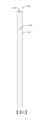
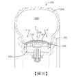
圖1大體圖示採用根據本揭示內容之教導構成之壓力感測總成104的自行車100。在此實施例中,形式為登山自行車的自行車100有車架108、在車架108前端附近的把手112、與用於支承自行車100之使用者(例如,騎乘者)於車架108上的座椅或座墊116。自行車100也包括第一或前輪120與第二或後輪124。前輪120由車架108的前叉128攜載且支承車架108的前端,同時後輪124由車架108的後叉132攜載且支承車架108的後端。在一具體實施例中,車架108的後端可由後懸吊組件(未圖示)支承。自行車100也有傳動系統(drive train)140,其具有可操作地經由鏈條148耦接至在後輪124旋轉軸線附近之後飛輪(rear cassette)的曲柄總成144。也可明白,自行車100可包括附加組件,例如,前撥鏈器(front derailleur)152、後撥鏈器156、自行車電腦、耳機及其類似者。FIG. 1 generally illustrates a
儘管圖1的自行車100為登山自行車,然而壓力感測總成104,包括揭露於本文之特定具體實施例以及替代具體實施例,可實作於其他類型的自行車上。例如,壓力感測總成104可與公路自行車和有機械(例如,纜線、液壓、氣動等等)及非機械(例如,有線、無線)傳動系統的自行車結合使用。Although the
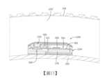
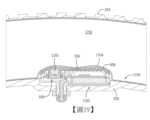
從圖2至圖4可明白,在此實施例中與前輪120相似的自行車100後輪124包括輪緣200與可移除地安裝至輪緣200的充氣輪胎204。更特別的是,充氣輪胎204的一部份設置在輪緣200的胎床208內且接合胎床208的輪胎接合面210(參考圖4),致使充氣輪胎204牢牢地安裝至輪緣200。如以下所詳述的,充氣輪胎204可為有內胎輪胎(tubed tire,亦即,含有內胎者),無內胎式輪胎(亦即,不含內胎者),或一些其他類型的輪胎。壓力感測總成104可附接至輪緣200且可操作地耦接至充氣輪胎204,致使壓力感測總成104能夠偵測或感測充氣輪胎204中之充氣腔室的壓力,例如,可由設置於充氣輪胎204內部中的內胎界定,由充氣輪胎204的內部與充氣輪胎204的密封件及/或一或多個其他組件界定。接著,壓力感測總成104能夠指示或傳輸偵得或感測壓力給自行車100的使用者。因此,自行車100的使用者可輕易快速地檢查前、後輪120、124的壓力而不必訴諸使用上述習知泵浦及量規系統。As can be seen from FIGS. 2 to 4 , the
在一具體實施例中,壓力感測總成104設置於輪緣在閥桿(valve stem)105的徑向對側可操作地允許添加及/或移除充氣輪胎204的空氣,如在說明圖1前輪120時所述。在此組態中,壓力感測總成104的質量可用來平衡及/或抵消閥桿105的質量。在一具體實施例中,該輪緣可至少包括第一孔與第二孔以各自有利於閥桿105與壓力感測總成104兩者的安裝。第一孔與第二孔可設置在輪子的徑向相對兩側上。In one embodiment, the
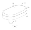
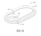
圖5至圖7圖示形式為壓力感測總成500的壓力感測總成104之第一實施例,其係可移除地附接至輪緣200,特別是輪緣200的胎床208,且可操作地耦接至充氣輪胎204。在此實施例中,壓力感測總成500包括殼體504與經由車架元件512耦接至殼體504的壓力傳輸構件508。殼體504最好由實質剛性材料製成,例如尼龍、聚碳酸酯/abs合金(PC/ABS)、或任何其他合適材料。殼體504有由基底516界定的實質環形形狀,從基底516向上延伸的第一壁部520,與從基底516向下延伸的第二壁部522。第一壁部520有第一實質環形部份524與在相對於基底516進一步向上延伸之前從第一部份524徑向向內延伸的第二部份528。第二壁部522有小於基底516與第一壁部520中之各者之外徑的外徑。在圖6及圖7清楚可見,開口530形成或界定於基底516且延伸穿過第二壁部522。開口530的尺寸及形狀經製作成可收容壓力感測總成500的光傳輸元件,例如光管,以下會更詳細地說明。FIGS. 5-7 illustrate a first embodiment of a
圖示於圖5至圖7之壓力傳輸構件508的形式最好為由實質不抗拒外加運動或力之順應性材料製成的牆體,例如硫化熱塑彈性體、矽氧樹脂橡膠、乙烯丙烯二烯單體(EPDM)橡膠或其類似者。壓力傳輸構件508因此在此可稱為偏轉構件或順應性構件,或更特別的是,壓力傳輸壁。在此實施例中,壓力傳輸構件508移動或偏轉以響應外加力或壓力。不過,在其他實施例中,壓力傳輸構件508可以不移動或偏轉,但是會改為只是不抗拒力或壓力。但是,在所有這些實施例中,壓力傳輸構件508經組配為可傳輸充氣輪胎204之充氣腔室的壓力給壓力感測總成500的其他組件。The
壓力傳輸構件508有固定於周壁520第二部份528與車架元件512之間的周緣532,致使壓力傳輸構件508固定於定位。壓力傳輸構件508也有在周緣532徑向內側且從周緣532向外突出的中央部份536,致使在壓力傳輸構件508耦接至殼體504時,壓力傳輸構件508的中央部份536在由殼體504界定的平面540外或與其隔開。在此實施例中,壓力傳輸構件508向外突出,亦即,有凸形,然而在其他實施例中,壓力傳輸構件508可改為有凹形或一些其他形狀。The
參考圖6,壓力感測總成500也包括感測腔室550。感測腔室550為由殼體504及壓力傳輸構件508界定的密封腔室。當壓力感測總成500附接至輪緣的胎床208時,將壓力感測總成的感測腔室550配置或定位成可經由壓力傳輸構件508來偵測或感測充氣輪胎204的壓力。更特別的是,壓力傳輸構件508與充氣輪胎204的充氣腔室壓力連通,致使充氣輪胎204的充氣腔室基於充氣輪胎204之充氣腔室的壓力來施加一力F於壓力傳輸構件508上。因此至少在此實施例中,壓力傳輸構件508相對於殼體504可移動或偏轉以響應充氣腔室的壓力(例如,響應壓力變化)。Referring to FIG. 6 , the
由於感測腔室550部份由壓力傳輸構件508界定,感測腔室550接著有追蹤或對應至充氣輪胎204之充氣腔室壓力的壓力。因此,例如,當充氣輪胎204的充氣腔室壓力低時,相較於在充氣輪胎204的充氣腔室壓力高(因為施加至壓力傳輸構件508的力較低)時,壓力傳輸構件508相對於殼體504的平面540會進一步向外突出,致使相較於在充氣輪胎204的充氣腔室壓力(較)高時,感測腔室550的容積在充氣輪胎204的充氣腔室壓力較低時較大(且其中的壓力較低)。Since sensing
壓力感測總成500進一步包括印刷電路板總成(PCBA)554,以及與PCB 554實體及通訊連接的壓力感測機構558。如圖示,PCBA 554抵靠殼體504的基底516就位,致使PCBA 554設置在感測腔室550中。在此實施例中,PCBA 554包括基板560與耦接(例如,附接、施加)至基板560的印刷電路板(PCB)561,亦即,電路。基板560大體形成PCBA 554的結構及/或形狀。在此實施例中,基板560有環形形狀且包括圓形孔口562,其尺寸經製作及配置成可收容壓力感測機構558。不過,在其他實施例中,可改變基板560的形狀及/或尺寸。基板560可為可操作以形成PCB 561之下層附件的任何物質。例如,可使用矽、二氧化矽、氧化鋁、藍寶石、鍺、砷化鎵(「GaAs」)、矽與鍺的合金、或磷化銦(「InP」)。基板560可呈剛性或撓性。基板560可為一基板材料連續件或多件。在此實施例中,PCB 561包括耦接至基板560的許多電子組件或由彼等形成,例如,微控制器600、第一無線通訊裝置604、第二無線通訊裝置608、發光元件610、及感測器612。在其他實施例中,PCB 561可包括附加、較少或不同的組件。例如,PCB 561可以只包括一個無線通訊裝置。The
在此實施例中,壓力感測機構558的形式為感測器殼體564與配置在感測器殼體564中的壓力感測元件(例如,感測器)565。例如,壓力感測元件558可為由TE Connectivity公司所製造的。感測器殼體564有延伸穿過圓形孔口562的圓柱形部份566,與抵靠基板560之底面574就位的凸緣部份570以使壓力感測機構558耦接至PCBA 554的基板560。In this embodiment, the
照此,壓力感測機構558的一部份躺在由殼體504界定的平面540中,同時壓力感測機構558的其餘部份(例如,凸緣部份570)在與壓力傳輸構件508之中央部份536相反的方向與平面540隔開。換言之,壓力傳輸構件508的中央部份536與壓力感測機構558的一實質部份在平面540的相對兩側。因此,壓力感測機構558位在感測腔室550中,致使壓力感測機構558可偵測或感測感測腔室550中的壓力,如上述,其係追蹤或對應至充氣輪胎204的充氣腔室壓力。同時,由於感測腔室550被密封,壓力感測機構558與可能在充氣腔室中(例如,在充氣腔室不包括內胎時)可能以其他方式用來塞住壓力感測機構558的任何密封膠流體隔離。As such, a portion of
還有,壓力感測總成500包括電源578。電源578大體經組配為可供電給總成500的各種組件。在此實施例中,電源578為抵靠PCB 554與底面574相反之正面588就位的電池。該電池可為特別訂做或組配的電池,或可為標準電池,例如CR 2016、CR 2012、CR 2016或CR 2032電池。在其他實施例中,電源578可位於他處及/或可改為採用組合多個電池及/或其他電力提供裝置的組合形式。Also,
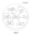
此時參考圖8,提供壓力感測元件558、微控制器600、第一及第二無線通訊裝置604、608、發光元件610及感測器612的方塊圖。如圖示,這些組件中之各者用某種方式耦接至PCB 554且通訊連接至微控制器600。應瞭解,可使用當前已知或未來會開發的任何技術來實現這些連接。Referring now to FIG. 8 , a block diagram of the
微控制器600大體包括處理器與儲存要由處理器執行之指令的記憶體。該處理器可包括通用處理器、數位訊號處理器,特殊應用積體電路(ASIC),場效可程式閘極陣列(FPGA)、類比電路、數位電路、彼等之組合、或其他當前已知或未來會開發的處理器。該處理器可為單一裝置或例如通過共享或平行處理之數個裝置的組合。該記憶體可為揮發性記憶體或非揮發性記憶體。該記憶體可包括以下各物中之一或多個:唯讀記憶體(ROM),隨機存取記憶體(RAM),快閃記憶體,電子抹除式可程式唯讀記憶體(EEPROM),或其他類型的記憶體。在一特別非限定性的示範具體實施例中,電腦可讀媒體可包括固態記憶體,例如記憶卡或容納一或多個非揮發性唯讀記憶體的其他封裝件。此外,該電腦可讀媒體可為隨機存取記憶體或其他揮發性可重寫記憶體。另外,該電腦可讀媒體可包括磁光或光學媒體,例如磁碟或磁帶或其他儲存裝置。因此,本揭示內容被視為包括電腦可讀媒體與其他等效物及可存入資料或指令的後繼媒體(successor media)中之任一或多個。該記憶體為非暫時性電腦可讀媒體且描述成為單一媒體。不過,用語「電腦可讀媒體」包括單一媒體或多個媒體,例如集中或分散式記憶體結構,及/或可操作以儲存一或多個指令集及其他資料的相關快取。用語「電腦可讀媒體」也應包括任何媒體,其能夠儲存、編碼或攜載指令集供處理器執行或造成電腦系統執行揭露於本文的方法及運作中之任一或多個。
在一替代具體實施例中,例如特殊應用積體電路、可程式化邏輯陣列及其他硬體裝置的專屬硬體實作可構造成可實作揭露於本文的方法中之一或多個。可包括各種具體實施例之設備及系統的應用可廣泛地包括各種電子及電腦系統。描述於本文的一或多個具體實施例實現功能可使用兩個或多個特定互連硬體模組或裝置,以及可在模組之間通訊且通過該等模組通訊的相關控制及資料訊號,或作為特殊應用積體電路的一部份。因此,本系統涵蓋軟體、韌體及硬體實作。In an alternative embodiment, dedicated hardware implementations such as application-specific integrated circuits, programmable logic arrays, and other hardware devices may be configured to implement one or more of the methods disclosed herein. Applications that may include the devices and systems of the various embodiments may broadly include a variety of electronic and computer systems. One or more embodiments described herein implement functionality using two or more specific interconnected hardware modules or devices, and associated controls and data that can communicate between and through the modules signal, or as part of an application-specific integrated circuit. Accordingly, the system encompasses software, firmware, and hardware implementations.
第一及第二無線通訊裝置604、608各自提供用於壓力感測總成500(例如,處理器600)與自行車100的其他組件或一或多個外部裝置(例如,行動電話、平板、耳機)之間的資料及/或訊號通訊。因此,例如,自行車100的使用者可使用外部裝置設定壓力感測總成500的預定壓力設定點(指示充氣輪胎204的所欲壓力)得到充氣輪胎204的當前壓力、改變壓力感測總成500的設定、及/或執行其他所欲機能。The first and second
在此實施例中,第一無線通訊裝置604包括使用ANT+™無線協定促進上述通訊的一或多個天線,同時第二無線通訊裝置608包括使用Bluetooth®促進上述通訊的一或多個無線電裝置。不過,在其他實施例中,第一及/或第二無線通訊裝置604、608可使用當前已知或未來會開發的任何標準來促進此類通訊,包括例如網際網路的標準與其他分封交換網路傳輸(例如,TCP/IP、UDP/IP、HTML、HTTP、HTTPS)、ZigBee、WiFi及/或AIREA™標準,或其類似者。也可明白,可用促進上述通訊中之任一或所有的單一無線通訊裝置604、608來體現第一及第二無線通訊裝置604、608。In this embodiment, the first
發光元件610大體經組配為可基於壓力感測機構558所感測或偵測的壓力來發光且傳訊給微控制器600。在此實施例中,發光元件610為發光二極體(LED),然而在其他實施例中,發光元件610可改為當前已知或未來會開發的任何光源。在此實施例中,發光元件610經組配為可發射3種不同顏色的光,綠光(亦即,有495奈米至570奈米之波長的光線),黃光或橙光(亦即,有570奈米至590奈米之波長或590奈米至620奈米之波長的光線),或彼等之混合,以及紅光(亦即,有620奈米至750奈米之波長的光線),且各種顏色的光與壓力感測總成500所感測之充氣輪胎204的不同壓力關聯。例如,在充氣輪胎204的壓力大於預定設定點(例如,出廠設定或由自行車100使用者設定)時可發射綠光,在充氣輪胎204的壓力大體等於或剛好低於預定設定點時可發射黃光或橙光,以及在充氣輪胎204的壓力遠低於預定設定點時可發射紅光以指示充氣輪胎204的壓力很低。當然,在其他實施例中,發光元件582可發射較少、附加及/或不同的顏色及/或可基於的準則來發射光線。The
感測器612大體經組配為可偵測或感測與自行車100結合執行的一或多個動作。在此實施例中,感測器612的形式為加速度計,其經組配為可判定(例如,識別、測量、或偵測、記錄)指示與後輪124結合執行之一或多個使用者動作的平移及/或旋轉運動。例如,該加速度計可判定輪子124當前正在旋轉(指示自行車100使用中),已被使用者旋轉(例如,向後旋轉),已被使用者搖晃,已被使用者擠壓(例如,雙重擠壓),已被使用者拍打(例如,兩三次),使用者已下車,已被使用者平移(例如,左右移動)及其類似者。替換地或附加地,感測器612可包括其他感測器,例如,振動感測器、陀螺儀、觸控或觸覺感測器,及/或任何其他已知或未來會開發用於以判定與自行車100結合執行的這些或其他動作中之一或多個為目的的感測器。
運作時,微控制器600得到指示來自壓力感測機構558之感測腔室550壓力的資料(指示充氣輪胎204的充氣腔室壓力)。接著,微控制器600可傳輸得到的資料給第一及第二無線通訊裝置604、608(例如,傳輸給自行車100的其他組件,例如,前撥鏈器152、後撥鏈器156、自行車電腦、及/或外部裝置),以及給發光元件610(用以基於充氣輪胎204的充氣腔室壓力來發射光線)。In operation, the
不過,由於壓力感測機構558、第一及第二無線通訊裝置604、608和發光元件610傾向相當快地消耗電源578,壓力感測總成500可用不同的電源模式運作以便儘可能在任何時候最小化這些組件的使用量。在此實施例中,壓力感測總成500可用3種不同模式運作:甦醒模式、睡眠模式與沉睡模式。在其他實施例中,壓力感測總成500可用更多或更少及/或不同不同的模式運作。例如,壓力感測總成500可以只用甦醒模式與睡眠模式運作。However, since
在壓力感測總成500處於甦醒模式時,感測總成500全面運作。不過,在壓力感測總成500處於睡眠模式時,總成500可操作,但是發光元件610被關掉,第一及第二無線通訊裝置604、608中之一或兩者被關掉,且壓力感測機構558以減少的速率感測或偵測壓力,致使總成500使用較少的電力。最後,在壓力感測總成500處於沉睡模式時,總成500使用最少數量的電力,因為壓力感測機構558、裝置604、608和發光元件610被關掉,同時微處理器600與感測器612最低限度地活動使得彼等可偵測命令壓力感測總成500以回到睡眠模式或甦醒模式的喚醒訊號。When the
基於壓力感測機構558、感測器612、預定設定,由自行車100使用者輸入的設定(例如,經由外部裝置)所得到的資料、其他理由、或彼等之組合,壓力感測總成500大體在這些模式之間切換。例如,在自行車100的使用者主動組配總成500(例如,經由外部裝置)時,以響應外部裝置所送出的喚醒訊號,以及在充氣輪胎204的壓力改變時,壓力感測總成500在電力感測總成500第一次通電時可以甦醒模式運作。例如,當充氣輪胎204的充氣腔室壓力在預定時間內沒有改變但是感測器612偵測到自行車100正在使用時,壓力感測總成500可切到睡眠模式,以及例如,當感測器612沒有偵測到與輪子120、124關聯的任何運動時,可切到沉睡模式。Based on
請再參考圖6及圖7,壓力感測總成500進一步包括形式為光管620的光傳輸元件,它最好由透明材料製成,例如聚碳酸酯或壓克力。為了散佈或傳輸發光元件610所發射的光線給自行車100的使用者,光管620與發光元件610通訊。為此目的,光管620設置於開口530中,致使光管620的第一端624緊鄰PCB 554,尤其是,LED 610,而且光管620的第二端628位於或鄰接第二壁部522的末端632。儘管在圖5至圖7看不到,然而應瞭解,第二壁部522的末端632與光管620的第二端628都延伸穿過形成於輪緣之胎床208的開口,致使末端628、632在輪緣200外。鏡片636耦接至第二壁部522以使光管620留在開口530內且聚焦及顯示LED 610所發射且傳輸通過光管620的光線。最好由例如光管620之透明材料製成的鏡片636有設置在開口530內且包圍光管620之第二端628的第一部份640,與抵靠第二壁部522之末端632就位的第二部份644,其設置在開口530外,儘管圖5至圖7看不到,它也設置在形成於輪緣200的開口外。因此,自行車100的使用者可看到鏡片636的一部份,致使使用者可看到LED 610所發射的光線。再者,由於發光元件610基於充氣輪胎204在被壓力感測總成500感測到時的充氣腔室壓力來發射光線,自行車100的使用者可快速輕易地以視覺方式得到充氣輪胎204的壓力。Referring to FIGS. 6 and 7 again, the
圖9至圖12圖示壓力感測總成104的第二實施例,形式為壓力感測總成1100,它經由扣件1102(例如,螺帽)可移除地附接至輪緣200,特別是輪緣200的胎床208,且可操作地耦接至充氣輪胎204的充氣腔室1103。壓力感測總成1100包括與壓力感測總成500相同的一些組件,這些組件則用相同的元件符號表示,但是與壓力感測總成500不同處詳述於下文。9-12 illustrate a second embodiment of a
首先,壓力感測總成1100有與壓力感測總成500之殼體504不同的殼體1104。在此實施例中,殼體1104為由第一或上層殼體部份1108與耦接至第一殼體部份1108之第二或下層殼體部份1112形成的兩件式殼體(例如,經由滑入配合或或其他連接)。第一殼體部份1108有由第一部份1116與向上及向內延伸且外徑小於第一部份1116之第二部份1120界定的實質環形形狀。因此,第二部份1120的形狀做成可防止壓力傳輸構件508阻塞感測腔室。圓形孔口1124延伸穿過第一及第二部份1116及1120。第一殼體部份1108也包括V形軌道1126,其形成於第二部份1120中以防止壓力傳輸構件508夾斷及隔離壓力感測機構558。同時,第二殼體部份1112有與上述殼體504實質類似的結構,但是,不像殼體504,第二殼體部份1112包括大小經製作成可收容電源578於其中的圓形孔口1128。First, the
第二,壓力感測總成1100包括兩個腔室而不是出現於壓力感測總成500的單一感測腔室。更特別的是,壓力感測總成包括第一或感測腔室1150與第二腔室1154。第一腔室1150為由第一殼體部份1108及壓力傳輸壁508界定的密封腔室。藉由比較圖7與圖13,應瞭解,第一腔室1150有比上述感測腔室550小的容積。第二腔室1154由第一及第二殼體部份1108、1112與可移除地耦接至第二殼體部份1112的門1158界定。如同第一腔室1150,第二腔室1154用密封元件1160密封,例如,由丁腈橡膠(Buna-N)或任何其他合適材料製成的O環,其配置於PCBA 554的基板560上且包圍壓力感測機構558以確保第二腔室1154與第一腔室1150阻隔。Second,
如圖10清楚所示,第一殼體部份1108,且更特別的是,第二部份1120,其形狀經製作成可防止壓力傳輸構件508阻塞感測腔室1154。例如,在感測腔室1154填滿例如空氣或氮氣之可壓縮流體時,這個特別重要,藉此第二部份1120可提供流動路徑用於使感測腔室1154與壓力感測機構558的壓力保持相等,從而確保在壓縮狀態下腔室1154仍可能有準確的讀數。另外,如圖12所示,第一殼體部份1108視需要包括從第一部份1116向外延伸(在此情形下,向下)的一對突出物1161(例如,栓體)。突出物1161經配置成有助於使PCBA 554與感測腔室1150分離且流體隔離。As best seen in FIG. 10 , the
如圖11清楚所示,基板560、電源578、微控制器600及光管620設置在第二腔室1154中,且基板560配置在第一及第二殼體部份1108、1112之間,電源578設置在孔口1128中,以及光管620配置在與開口530一樣的開口1162中。儘管壓力感測機構558延伸穿過孔口1124致使它耦接至基板560,然而壓力感測機構558經定位成與感測腔室1150流體連通。這允許壓力感測機構558感測或偵測感測腔室1150中的壓力。壓力感測機構558可接著產生指示感測或偵得壓力的訊號(在有些情形下,這會用微控制器的處理器來達成)。該訊號可傳達至PCBA 554用以傳輸至自行車100的其他組件(例如,壓力感測總成1100的發光元件610及光管620)。同時,由於第一及第二腔室1150、1154被密封,第二腔室1154與第一腔室1150流體隔離。因此,在第一腔室1150填滿壓力傳輸媒體(例如,不可壓縮流體,亦即,在工作壓力下不會壓縮的流體)時,例如PCBA 554及電源578的組件有益地與該流體隔離,從而保護該等組件。As best shown in FIG. 11 , the
第三,由於電源578在部份由可拆裝門1158界定的第二腔室1154中,藉由簡單地從殼體1104卸下門1158,可移除且修理或更換電源578。第四,由於電源578的定位,微處理器600、第一及第二無線通訊裝置604、608和感測器612在此實施例中配置於基板560的正面588上而不是基板560的底面574(在說明圖5至圖7時所述的實施例就是如此)。Third, since the
儘管壓力感測總成500與壓力感測總成1100有前述差異,然而壓力感測總成1100以與壓力感測總成500類似的方式運作來偵測或感測充氣輪胎204的充氣腔室壓力。另外,壓力感測總成1100可用與壓力感測總成500類似的方式傳送(例如,視覺指示)偵得或感測壓力給自行車100的使用者。Despite the aforementioned differences between
圖13圖示形式為壓力感測總成1200之壓力感測總成104的第三實施例,它可移除地附接至輪緣200,特別是輪緣200的胎床208,且可操作地耦接至充氣輪胎204中的充氣腔室1202。壓力感測總成1200實質類似壓力感測總成1100,其中相同的元件用相同的符號表示。不過,壓力感測總成1200與壓力感測總成1100不同處詳述於下文。FIG. 13 illustrates a third embodiment of a
首先,不像壓力感測總成1100,壓力感測總成1200不包括發光元件610、光管620或鏡片636。因此,壓力感測總成1200有稍微與殼體1104不同的殼體1204,因為它不包括類似壁部522的第二壁部或類似開口1162的開口。結果,應瞭解,壓力感測總成1200可整個設置在輪緣200的胎床208內(亦即,自行車100的使用者看不到壓力感測總成1200的任何部份)。黏著劑可用來使壓力感測總成1200固定於輪緣200的胎床208內。First, unlike
第二,不像壓力感測總成1100,壓力感測總成1200的感測腔室1150填滿壓力傳輸媒體。該壓力傳輸媒體最好為不可壓縮流體,例如水、油、剎車流體(例如,DOT)、或矽氧樹脂凝膠。不過,在有些情形下,可使用可壓縮流體,例如氣體(例如,氮氣、空氣)。在任一情形下,感測腔室1150中存在流體可能有助於保護壓力感測總成1200的電子組件,例如,PCBA 554、壓力感測機構558及電源578。Second, unlike
圖14圖示形式為壓力感測總成1300之壓力感測總成104的第四實施例,它可移除地附接至輪緣200,特別是輪緣200的胎床208,且可操作地耦接至充氣輪胎204。壓力感測總成1300實質類似壓力感測總成1100,其中類似的組件用相同的元件符號表示。壓力感測總成1100與壓力感測總成1300的第一個差異與耦接至PCB 554的組件中之一些的定位有關。更特別的是,在壓力感測元件1300中,微控制器600、第一及第二無線通訊裝置604、608和感測器612配置在PCB 554的底面上。應瞭解,這些組件在圖14看不到,因為電源578在第二腔室1154中的位置。第二,不像壓力感測總成1100,壓力感測總成1300包括耦接至感測器殼體564且位於壓力感測元件565上方的第二壓力傳輸構件1304,例如撓性或順應性隔膜。以此方式定位後,隔膜1304藉由使壓力感測元件565與感測腔室1150流體隔離來保護壓力感測元件565。FIG. 14 illustrates a fourth embodiment of a
圖15及圖16圖示形式為壓力感測總成1400之壓力感測總成104的第五實施例,它可移除地附接至輪緣200,特別是輪緣200的胎床208,且可操作地耦接至充氣輪胎204。壓力感測總成1400實質類似壓力感測總成1100,其中類似的組件用相同的元件符號表示。不過,不像壓力感測總成1100,壓力感測總成1400包括壓力感測元件565的參考端口(reference port)1404。參考端口1404經形成可穿過第二殼體部份1112的數個部份且使第二腔室1154與大氣流體耦接。因此,位在第二腔室1154中的壓力感測元件565與大氣呈流體連通。結果,在此實施例中,壓力感測器565起相對壓力感測器的作用,藉此大氣壓力用來作為參考壓力且壓力感測元件565偵測或感測第一腔室1150中從而輪胎204中的充氣腔室中相對於該參考壓力的的壓力。這與都沒有參考端口的上述實施例相反。因此,在這些實施例中,壓力感測元件565起絕對壓力感測器的作用,藉此壓力感測元件565偵測或感測感測腔室中從而輪胎204中相對於絕對零的壓力。Figures 15 and 16 illustrate a fifth embodiment of a
另外,不像壓力感測總成1100,壓力感測總成1400視需要包括氣體可滲透但是其他不可滲透的屏障1408。屏障1408配置於感測機構558(其包括壓力感測器567)與參考端口1404之間。以此方式定位後,屏障1408允許壓力感測器567與大氣壓力連通(經由參考端口1404)但是阻止例如不可壓縮流體的流體在大氣、壓力感測器567之間流動。Additionally, unlike
如以上所簡述的,描述於本文的任一壓力感測總成可與有內胎輪胎(亦即,有內胎的輪胎)結合使用,藉此充氣腔室由內胎界定,或與無內胎式輪胎(亦即,沒有內胎的輪胎)結合使用,藉此充氣輪胎由輪胎本身與(視需要)輪胎的密封件界定。例如,圖17至圖19圖示壓力感測總成1100,其係與形式為有內胎1700之有內胎輪胎的充氣輪胎204結合使用。因此,在此實施例中,由內胎1700界定的充氣腔室1702對壓力傳輸構件508施加對應至充氣腔室1702之壓力的向外力F(在此情形下,為向下)。作為另一實施例,圖20至圖22圖示與形式為無內胎式輪胎(亦即,沒有例如內胎1700之內胎的輪胎)之充氣輪胎204結合使用的相同壓力感測總成1100。因此,在此實施例中,由充氣輪胎204之內部1904界定的充氣腔室1900對壓力傳輸構件508施加基於充氣腔室1900之壓力的向外力F(在此情形下,為向下)。As briefly mentioned above, any of the pressure sensing assemblies described herein may be used in conjunction with tubed tires (i.e., tires that have a tube), whereby the inflation chamber is defined by the tube, or with tubeless tires. (that is, a tire without an inner tube) are used in conjunction whereby the pneumatic tire is defined by the tire itself and (if necessary) the seals of the tire. For example, FIGS. 17-19 illustrate a
如圖17及圖18所示,壓力傳輸構件508,特別是壓力傳輸構件508的中央部份536,直接接合充氣輪胎204內胎1700的形狀相似底壁1704。由內胎1700界定之充氣腔室1702內的壓力產生向外力F,其係經由底壁1704施加至壓力傳輸構件508且對應至充氣輪胎204的壓力。以此方式,壓力傳輸構件508能夠偵測或感測充氣輪胎204的充氣腔室1702壓力。由於感測腔室1150部份由壓力傳輸構件508界定,感測腔室1150接著有追蹤或對應至充氣輪胎204之充氣腔室1702壓力的壓力。壓力感測機構558與感測腔室1150流體連通,因而感測或偵測感測腔室1150中的壓力,它接著傳達至PCBA 554,特別是微控制器600,用以按需要傳輸至其他組件。As shown in FIGS. 17 and 18 , the
此時翻到圖19,例如,在由內胎1700界定之充氣腔室1702的壓力增加(或大於圖17及圖18的充氣腔室1702壓力)時,由底壁1704對壓力傳輸構件508施加的向下力F(特別是,中央部份536)也增加。在有些情形下,儘管不總是這樣,增加的壓力會造成壓力傳輸構件508向內彎曲,且特別是中央部份536,如圖19所示,從而減少感測腔室1150的容積。在任何情形下,壓力傳輸構件508偵測或感測增加的壓力。接著,增加的壓力被壓力感測機構558感測而將增加的壓力傳達至PCBA 554。Now turn to Fig. 19, for example, when the pressure of the
反之,當充氣腔室1702的壓力減少(或小於圖17及圖18的充氣腔室1702壓力),由底壁1704對壓力傳輸構件508(特別是,中央部份536)施加的向下力也減少。在有些情形下,儘管不總是這樣,減少的壓力會造成壓力傳輸構件508向外彎曲(未圖示),特別是中央部份536。在任何情形下,壓力傳輸構件508偵測或感測減少的壓力。接著,減少的壓力被壓力感測機構558感測而將減少的壓力傳達至PCBA 554。Conversely, when the pressure of the
如圖20及圖21所示,壓力傳輸構件508,特別是壓力傳輸構件508的中央部份536,與充氣輪胎204的充氣腔室1900直接壓力連通。充氣腔室1900的壓力因此產生施加於壓力傳輸構件508的向外力F(在此情形下,是向下),且力F與充氣輪胎204之充氣腔室1900壓力對應。以此方式,壓力傳輸構件508能夠偵測或感測充氣輪胎204的充氣腔室1900壓力。由於感測腔室1150部份由壓力傳輸構件508界定,感測腔室1150接著有追蹤或對應至充氣輪胎204之充氣腔室1900壓力的壓力。壓力感測機構558與感測腔室1150流體連通,因而感測或偵測感測腔室1150中的壓力,它接著傳達至PCBA 554,特別是微控制器600,用以按需要傳輸至其他組件。As shown in FIGS. 20 and 21 , the
此時翻到圖22,例如,在充氣腔室1900的壓力增加(或大於圖20及圖21的腔室1900壓力)時,施加於壓力傳輸構件508(特別是,中央部份536)的向下力F也增加。在有些情形下,儘管不總是這樣,增加的壓力會造成壓力傳輸構件508向內彎曲,特別是中央部份536,如圖22所示。在任何情形下,壓力傳輸構件508偵測或感測增加的壓力。接著,增加的壓力被壓力感測機構558感測而將增加的壓力傳達至PCB 554A。Now turn to FIG. 22, for example, when the pressure of the
反之,當充氣腔室1900中的壓力減少(或小於圖20及圖21的腔室1900壓力)時,由內部2000中空氣對壓力傳輸構件508(特別是,中央部份536)施加的向下力F也減少。在有些情形下,儘管不總是這樣,減少的壓力會造成壓力傳輸構件508向外彎曲(未圖示),特別是中央部份536。在任何情形下,壓力傳輸構件508偵測或感測減少的壓力。接著,減少的壓力被壓力感測機構558感測而將減少壓力傳達至PCB 554A。Conversely, when the pressure in the
有益的是,儘管壓力感測機構558能夠經由壓力傳輸壁508來偵測或感測充氣輪胎204之充氣腔室1900壓力,然而壓力感測機構558與充氣輪胎204的內部1904流體隔離。因此,壓力感測機構558與用來密封充氣輪胎204之數個部份的任何輪胎密封膠(例如,Stan’s,Orange,Slime公司的等等)流體隔離且受其保護。Beneficially, the
描述於本文之具體實施例的圖解說明旨在提供各種具體實施例之結構的一般了解。圖解說明無意用作利用描述於本文之結構或方法的設備及系統中之所有元件及特徵的完整描述。熟諳此藝者在審查本揭示內容後可明白許多其他具體實施例。其他具體實施例可加以利用且可衍生自本揭示內容,致使可做出結構及邏輯上的取代及變更而不脫離本揭示內容的範疇。另外,圖解說明僅具代表性且可能不按比例繪製。圖解說明內的某些比例可能被誇大,同時可能最小化其他的比例。因此,本揭示內容及附圖應被視為圖解說明用而不是限制。The illustrations of the embodiments described herein are intended to provide a general understanding of the structure of various embodiments. The illustrations are not intended to be a complete description of all elements and features in devices and systems that utilize the structures or methods described herein. Many other embodiments will be apparent to those skilled in the art upon examination of the present disclosure. Other embodiments may be utilized and derived from this disclosure, such that structural and logical substitutions and changes may be made without departing from the scope of this disclosure. Additionally, illustrations are representative only and may not be drawn to scale. Certain proportions within the illustrations may be exaggerated, while others may be minimized. Accordingly, the disclosure and drawings are to be regarded as illustrative rather than restrictive.
儘管本文包含許多細節,然而它們不應被視作本發明範疇或可主張內容的限制反而是本發明特定具體實施例之專屬特徵的描述。本專利說明書在獨立具體實施例背景下提及的某些特徵也可以組合成單一具體實施例的方式實現。反之,在單一具體實施例背景下提及的各種特徵也可以把多個具體實施例分成個體或任何適當次組合的方式實現。此外,儘管以上把特徵描述成是以某些組合的方式甚至如起初所主張的起作用,然而源於所主張之組合的一或更多特徵在某些情形下可從該組合刪除,以及所主張之組合可針對次組合或次組合的變體。While there are many specifics contained herein, these should not be construed as limitations on the scope of the invention or of what may be claimed, but rather as descriptions of features specific to particular embodiments of the invention. Certain features that are mentioned in this patent specification in the context of separate embodiments can also be implemented in combination in a single embodiment. Conversely, various features that are mentioned in the context of a single embodiment can also be implemented in multiple embodiments individually or in any suitable subcombination. Furthermore, although features are described above as functioning in certain combinations, even as originally claimed, one or more features resulting from a claimed combination may in some cases be deleted from that combination, and the stated A claimed combination may be for a subcombination or a variation of a subcombination.
同樣,儘管運作及/或動作以特定次序描繪於附圖和描述於本文,然而這不應被理解為需要按照圖示特定次序或順序次序來執行此類運作,或執行所有圖示運作,以實現合意的結果。在某些情況中,多工及平行處理可能是有利的。此外,上述具體實施例之各種系統組件的分離不應被理解為所有具體實施例需要此類分離,且應瞭解,任何提及程式組件及系統通常可一起集成於單一軟體產品中或封裝成多個軟體產品。Likewise, although operations and/or actions are depicted in the drawings and described herein in a particular order, this should not be understood as requiring that such operations be performed in the particular order shown or in sequential order, or that all illustrated operations be performed, to achieve desired results. In some cases, multiplexing and parallel processing may be advantageous. Furthermore, the separation of various system components of the embodiments described above should not be interpreted as requiring such separation in all embodiments, and it should be understood that any mentioned program components and systems can generally be integrated together in a single software product or packaged as multiple a software product.
本揭示內容之一或多個具體實施例在本文中可單獨地及/或共同地僅藉由「發明」一詞指代以用於方便且不欲自行將本申請案之範疇限制於任何特定發明或發明性概念。此外,雖然本文已例示且描述特定具體實施例,但應瞭解,經設計來達成相同或類似目的的任何後續配置可取代所展示特定具體實施例。本揭示內容意欲涵蓋各種具體實施例之任何及所有後續調適或變化。熟諳此藝者在審閱描述後可明白上述具體實施例與未具體描述於本文之其他具體實施例的組合。One or more embodiments of the present disclosure may be referred to herein, individually and/or collectively, by the term "invention" only for convenience and without intending to limit the scope of the application to any particular embodiment. Invention or inventive concept. Additionally, while specific embodiments have been illustrated and described herein, it should be understood that any subsequent arrangement, designed to achieve the same or a similar purpose, may be substituted for the specific embodiment shown. This disclosure is intended to cover any and all subsequent adaptations or variations of various embodiments. Combinations of the above-described embodiments, and other embodiments not specifically described herein, will be apparent to those of skill in the art upon review of the description.
提供發明摘要以遵守美國專利法實施細則37 C.F.R.的1.72(b)節,且在它不會用來解釋或限制申請專利範圍之範疇或意義的理解下提交。此外,在實施方式中,為了使本揭示內容流暢,各種特徵可在單一具體實施例中群組在一起或描述。本揭示內容不應被解釋為反映如下意圖:所主張之具體實施例需要多於明確敘述於每一請求項的特徵。反而,如下列請求項所反映的,發明專利標的可針對少於所揭示具體實施例中之任一者的所有特徵。因此,將下列請求項併入實施方式,其中每一請求項憑自身單獨定義所主張的專利標的。The Abstract of the Invention is provided to comply with Section 1.72(b) of 37 C.F.R. of the United States Patent Law and is filed with the understanding that it will not be used to interpret or limit the scope or meaning of the claimed claims. Furthermore, in implementations, various features may be grouped or described in a single specific embodiment in order to streamline the disclosure. This disclosure is not to be interpreted as reflecting an intention that the claimed embodiments require more features than are expressly recited in each claim. Rather, as the following claims reflect, inventive subject matter may be directed to less than all features of any one of the disclosed embodiments. Accordingly, the following claims, each of which by itself defines claimed subject matter, are hereby incorporated into the embodiments.
意欲上述實施方式被視為具有圖解說明性而非限制性,且應瞭解,包括所有等效物的下列請求項旨在界定本發明的範疇。該等請求項不應被解讀為受限於提及次序或元件,除非另有說明該效果。因此,落入下列請求項及其等效物之精神及範疇的所有具體實施例被主張為本發明。It is intended that the above embodiments be considered as illustrative rather than restrictive, and it should be understood that the following claims, including all equivalents, are intended to define the scope of the invention. These claims should not be read as limited to the order or elements recited unless stated to that effect. Accordingly, all embodiments falling within the spirit and scope of the following claims and their equivalents are claimed to be inventions.
由上述討論,將可理解,本發明可以多種實施例形式體現,包含但不限於下列:From the above discussion, it will be appreciated that the present invention can be embodied in a variety of embodiments, including but not limited to the following:
實施例1:一種壓力感測總成,其經組配為可附接至有一輪胎與安裝至該輪胎之一輪緣的一自行車輪,該壓力感測總成包含:界定一平面的一殼體;耦接至該殼體的一壓力傳輸構件,該壓力傳輸構件有在第一方向偏離該平面的一中央部份;由該殼體與該壓力傳輸構件界定的一感測腔室;與在與該第一方向相反之第二方向偏離該平面的一感測元件,其中,該壓力傳輸構件經組配為可經由該感測腔室傳輸該輪胎中的壓力至該感測元件。Embodiment 1: A pressure sensing assembly assembled as a bicycle wheel attachable to a tire and mounted to a rim of the tire, the pressure sensing assembly comprising:a shell defining a plane;a pressure transmission member coupled to the housing, the pressure transmission member having a central portion offset from the plane in a first direction;a sensing chamber defined by the housing and the pressure transmitting member; anda sensing element offset from the plane in a second direction opposite the first direction,Wherein, the pressure transmission member is configured to transmit the pressure in the tire to the sensing element via the sensing chamber.
實施例2:如實施例1之壓力感測總成,其中,該壓力傳輸構件包含一偏轉構件。Embodiment 2: The pressure sensing assembly of Embodiment 1, wherein the pressure transmitting member comprises a deflection member.
實施例3:如實施例2之壓力感測總成,其中,該偏轉構件有一外凸外表面。Embodiment 3: The pressure sensing assembly of Embodiment 2, wherein the deflection member has a convex outer surface.
實施例4:如實施例1之壓力感測總成,其中,該壓力傳輸構件可移動以響應該輪胎中的壓力變化。Embodiment 4: The pressure sensing assembly of Embodiment 1, wherein the pressure transmitting member is movable in response to pressure changes in the tire.
實施例5:如實施例1之壓力感測總成,其中,該感測元件配置於該感測腔室中。Embodiment 5: The pressure sensing assembly of Embodiment 1, wherein the sensing element is disposed in the sensing chamber.
實施例6:如實施例1之壓力感測總成,其進一步包含:設置在該感測腔室內的一印刷電路板與耦接至該印刷電路板的一電源,其中,該感測元件設置在該印刷電路板上。Embodiment 6: The pressure sensing assembly according to Embodiment 1, which further includes: a printed circuit board disposed in the sensing chamber and a power supply coupled to the printed circuit board, wherein the sensing element is disposed on the printed circuit board.
實施例7:如實施例1之壓力感測總成,其進一步包含:設置在該感測腔室內的一印刷電路板;與一第一無線通訊器,其耦接至該印刷電路板且經組配為可傳輸指示該輪胎之感測壓力的資料。Embodiment 7: The pressure sensing assembly of Embodiment 1, which further includes:a printed circuit board disposed within the sensing chamber; andA first wireless communicator coupled to the printed circuit board and configured to transmit data indicative of the sensed pressure of the tire.
實施例8:如實施例1之壓力感測總成,其進一步包含:配置成鄰接該感測腔室的一第二腔室,該第二腔室與該感測腔室流體隔離,其中,該感測元件配置在該第二腔室中。Embodiment 8: The pressure sensing assembly of Embodiment 1, further comprising: a second chamber disposed adjacent to the sensing chamber, the second chamber being fluidly isolated from the sensing chamber, wherein, The sensing element is disposed in the second chamber.
實施例9:如實施例8之壓力感測總成,其進一步包含:設置在該第二腔室內的一印刷電路板;與一第一無線通訊器,其耦接至該印刷電路板且經組配為可傳輸指示該輪胎之感測壓力的資料。Embodiment 9: The pressure sensing assembly of Embodiment 8, which further comprises:a printed circuit board disposed within the second chamber; andA first wireless communicator coupled to the printed circuit board and configured to transmit data indicative of the sensed pressure of the tire.
實施例10:如實施例1之壓力感測總成,其進一步包含:一印刷電路板與耦接至該印刷電路板的一發光元件,該發光元件經組配為可發射指示該輪胎之感測壓力的光線。Embodiment 10: The pressure sensing assembly of Embodiment 1, which further comprises: a printed circuit board and a light emitting element coupled to the printed circuit board, the light emitting element is configured to emit a sense indicating the tire Light for measuring pressure.
實施例11:如實施例1之壓力感測總成,其進一步包含:設置在該感測腔室中的不可壓縮流體。Embodiment 11: The pressure sensing assembly of Embodiment 1, further comprising: an incompressible fluid disposed in the sensing chamber.
實施例12:如實施例1之壓力感測總成,其進一步包含:形成於該殼體中且與大氣呈流體連通的一參考端口;與配置在該感測元件與該參考端口之間的一氣體可滲透且流體不可滲透屏障。Embodiment 12: The pressure sensing assembly of Embodiment 1, which further comprises:a reference port formed in the housing and in fluid communication with atmosphere; andA gas permeable and fluid impermeable barrier is disposed between the sensing element and the reference port.
實施例13:一種自行車輪,其包含:一輪緣;安裝至該輪緣之一胎床的一輪胎;可附接至該輪緣的一壓力感測總成,該壓力感測總成包含:具有經組配為可接合該胎床之一表面的一殼體,該胎床有經組配為可接受該殼體的一輪胎接合面;與經配置成可測量該輪胎中之壓力的一感測元件。Embodiment 13: A bicycle wheel comprising:a rim;a tire fitted to a tire bed of the rim;A pressure sensing assembly attachable to the rim, the pressure sensing assembly comprising:having a casing configured to engage a surface of the tire bed having a tire engaging surface configured to receive the casing; andA sensing element configured to measure pressure in the tire.
實施例14:如實施例13之自行車輪,其中,該壓力感測總成進一步包含:一耦接的壓力傳輸壁;與由該殼體與該壓力傳輸壁界定的一感測腔室,其中,該壓力傳輸壁經組配為可經由該感測腔室傳輸該輪胎中之該壓力至該感測元件。Embodiment 14: The bicycle wheel of Embodiment 13, wherein the pressure sensing assembly further comprises: a coupled pressure transmission wall; and a sensing chamber defined by the housing and the pressure transmission wall, wherein , the pressure transmission wall is configured to transmit the pressure in the tire to the sensing element via the sensing chamber.
實施例15:如實施例14之自行車輪,其中,該感測腔室與該輪胎的內部流體隔離。Embodiment 15: The bicycle wheel of Embodiment 14, wherein the sensing chamber is fluidly isolated from the interior of the tire.
實施例16:如實施例13之自行車輪,其中,該輪胎無內胎。Embodiment 16: The bicycle wheel of Embodiment 13, wherein the tire is tubeless.
實施例17:如實施例13之自行車輪,其中,該壓力傳輸壁有一弧形外表面,且其中,該壓力傳輸壁可移動以響應該輪胎中的壓力變化。Embodiment 17: The bicycle wheel of Embodiment 13, wherein the pressure transmitting wall has a curved outer surface, and wherein the pressure transmitting wall is movable in response to pressure changes in the tire.
實施例18:如實施例13之自行車輪,其進一步包含:設置在該感測腔室內的一印刷電路板與耦接至該印刷電路板的一電源,其中,該感測元件設置在該印刷電路板上。Embodiment 18: The bicycle wheel according to Embodiment 13, further comprising: a printed circuit board disposed in the sensing chamber and a power source coupled to the printed circuit board, wherein the sensing element is disposed on the printed circuit board circuit board.
實施例19:如實施例14之自行車輪,其進一步包含:設置在該感測腔室內的一印刷電路板;與一第一無線通訊器,其耦接至該印刷電路板且經組配為可傳輸指示該輪胎之壓力的資料。Embodiment 19: the bicycle wheel of embodiment 14, which further comprises:a printed circuit board disposed within the sensing chamber; andA first wireless communicator coupled to the printed circuit board and configured to transmit data indicative of the tire pressure.
實施例20:如實施例14之自行車輪,其進一步包含:配置成鄰接該感測腔室一第二腔室,該第二腔室與該感測腔室流體隔離,其中,該感測元件配置在該第二腔室中。Embodiment 20: The bicycle wheel of Embodiment 14, further comprising: a second chamber disposed adjacent to the sensing chamber, the second chamber being fluidly isolated from the sensing chamber, wherein the sensing element disposed in the second chamber.
實施例21:如實施例20之自行車輪,其進一步包含:設置在該第二腔室內的一印刷電路板;與一第一無線通訊器,其耦接至該印刷電路板且經組配為可傳輸指示該輪胎之壓力的資料。Embodiment 21: The bicycle wheel according to Embodiment 20, which further comprises:a printed circuit board disposed within the second chamber; andA first wireless communicator coupled to the printed circuit board and configured to transmit data indicative of the tire pressure.
實施例22:如實施例13之自行車輪,其進一步包含:一印刷電路板與耦接至該印刷電路板的一發光元件,該發光元件經組配為可發射指示該輪胎之壓力的光線。Embodiment 22: The bicycle wheel of Embodiment 13, further comprising: a printed circuit board and a light emitting element coupled to the printed circuit board, the light emitting element is configured to emit light indicating the pressure of the tire.
實施例23:如實施例22之自行車輪,其進一步包含耦接至該發光元件的一光管與耦接至該光管的一鏡片,其中,該鏡片延伸穿過形成於該輪緣之該胎床中的一開口,致使該發光元件所發射的光線可看見。Embodiment 23: The bicycle wheel of Embodiment 22, further comprising a light pipe coupled to the light emitting element and a lens coupled to the light pipe, wherein the lens extends through the rim formed on the rim An opening in the fetal bed such that the light emitted by the luminescent element is visible.
實施例24:如實施例13之自行車輪,其中,該感測器總成可用不同的模式運作以響應與該輪胎關聯的使用者活動。Embodiment 24: The bicycle wheel of Embodiment 13, wherein the sensor assembly is operable in different modes in response to user activity associated with the tire.
100:自行車104:壓力感測總成105:閥桿108:車架112:把手116:座椅或座墊120:第一或前輪124:第二或後輪128:前叉132:後叉140:傳動系統144:曲柄總成148:鏈條152:前撥鏈器156:後撥鏈器200:輪緣204:充氣輪胎208:胎床210:輪胎接合面500:(壓力)感測總成/電力感測總成/總成504:殼體508:壓力傳輸構件512:車架元件516:基底520:第一壁部/周壁522:第二壁部524:第一實質環形部份528:第二部份530:開口532:周緣536:中央部份540:平面550:感測腔室554:印刷電路板總成(PCBA)554A:PCB558:(壓力)感測機構/壓力感測元件560:基板561:印刷電路板(PCB)562:圓形孔口564:感測器殼體565:壓力感測元件566:圓柱形部份567:壓力感測器570:凸緣部份574:底面578:電源582:發光元件588:正面600:微控制器604:第一無線通訊裝置608:第二無線通訊裝置610:發光元件612:感測器/加速度計620:光管624:第一端628:第二端632:末端636:鏡片640:第一部份644:第二部份1100:壓力感測總成1102:扣件1103:充氣腔室1104:殼體1108:第一或上層殼體部份1112:第二或下層殼體部份1116:第一部份1120:第二部份1124:圓形孔口1126:V形軌道1128:圓形孔口1150:第一或感測腔室1154:第二腔室1158:(可移除)門1160:密封元件1161:突出物1162:開口1200:壓力感測總成1202:充氣腔室1204:殼體1300:壓力感測總成1304:第二壓力傳輸構件1400:壓力感測總成1404:參考端口1408:屏障1700:內胎1702:充氣腔室1704:底壁1900:充氣腔室1904:內部2000:內部F:力100: Bicycle104: Pressure sensing assembly105: valve stem108: frame112: handle116: seat or cushion120: First or front wheel124: Second or rear wheel128: front fork132: rear fork140: Transmission system144: crank assembly148: chain152: Front derailleur156: Rear derailleur200: rim204: Pneumatic tire208: fetal bed210: tire joint surface500: (pressure) sensing assembly/power sensing assembly/assembly504: Shell508: Pressure transmission member512: frame element516: base520: the first wall/surrounding wall522: the second wall524: the first substantial circular portion528: Part Two530: opening532: Perimeter536: central part540: plane550: Sensing chamber554: Printed Circuit Board Assembly (PCBA)554A: PCB558: (Pressure) Sensing Mechanism/Pressure Sensing Element560: Substrate561: Printed Circuit Board (PCB)562: round orifice564: Sensor housing565: Pressure sensing element566: Cylindrical part567:Pressure sensor570: flange part574: Bottom578:Power582:Light emitting element588: front600: microcontroller604: The first wireless communication device608: The second wireless communication device610: Light emitting element612: Sensor/Accelerometer620: light pipe624: first end628: second end632: end636: Lens640: Part 1644:Part Two1100: Pressure sensing assembly1102: Fasteners1103: inflatable chamber1104: shell1108: first or upper shell part1112: second or lower shell part1116:Part 11120: Part Two1124: circular orifice1126: V-shaped track1128: round orifice1150: First or sensing chamber1154: second chamber1158: (removable) door1160: sealing element1161:Protrusion1162: opening1200: Pressure sensing assembly1202: inflatable chamber1204: shell1300: Pressure sensing assembly1304: second pressure transmission member1400: Pressure sensing assembly1404: Reference port1408: Barrier1700: inner tube1702: Inflatable chamber1704: bottom wall1900: Inflatable chamber1904: interior2000: InternalF: force
特別以隨附請求項提出咸信有新穎性的本發明特徵。參考以下結合附圖的說明可最佳地明白本發明及其目標和優點,附圖中類似的元件用相同的元件符號表示,其中:The features of the invention which are believed to be novel are set forth with particularity in the appended claims. The present invention and its objects and advantages are best understood by reference to the following description taken in conjunction with the accompanying drawings, in which like elements are designated by like reference numerals, wherein:
圖1的側視圖圖示採用根據本揭示內容之教導構成之壓力感測總成的自行車;Figure 1 is a side view illustration of a bicycle employing a pressure sensing assembly constructed in accordance with the teachings of the present disclosure;
圖2的側視圖圖示圖1自行車的自行車輪;Figure 2 is a side view illustrating the bicycle wheel of the bicycle of Figure 1;
圖3類似圖2,但是自行車輪的輪胎被移除;Figure 3 is similar to Figure 2, but with the bicycle wheel's tire removed;
圖4為圖3的上視圖;Fig. 4 is the top view of Fig. 3;
圖5的透視圖圖示採用於圖1自行車之壓力感測總成的第一實施例;FIG. 5 is a perspective view illustrating a first embodiment of a pressure sensing assembly employed in the bicycle of FIG. 1;
圖6為圖5之壓力感測總成的橫截面圖;FIG. 6 is a cross-sectional view of the pressure sensing assembly of FIG. 5;
圖7為圖5之壓力感測總成的展開圖;Fig. 7 is an expanded view of the pressure sensing assembly of Fig. 5;
圖8為圖5壓力感測總成之各種電子組件的方塊圖;8 is a block diagram of various electronic components of the pressure sensing assembly of FIG. 5;
圖9的橫截面圖圖示採用於圖1自行車之壓力感測總成的第二實施例,其圖示經由扣件附接至輪緣的壓力感測總成;Figure 9 is a cross-sectional view illustrating a second embodiment of a pressure sensing assembly employed in the bicycle of Figure 1, showing the pressure sensing assembly attached to the rim via fasteners;
圖10為圖9壓力感測總成之第二實施例從輪緣卸下時的橫截面圖;10 is a cross-sectional view of the second embodiment of the pressure sensing assembly of FIG. 9 when it is removed from the rim;
圖11為圖10壓力感測總成之第二實施例的展開圖;Fig. 11 is an expanded view of the second embodiment of the pressure sensing assembly in Fig. 10;
圖12的橫截面圖圖示採用於圖1自行車之壓力感測總成的第三實施例,其圖示經由黏著劑附接至輪緣的壓力感測總成;Figure 12 is a cross-sectional view illustrating a third embodiment of a pressure sensing assembly employed in the bicycle of Figure 1, showing the pressure sensing assembly attached to the rim via adhesive;
圖13的透視圖圖示壓力感測總成之第二實施例的組件之底面;Figure 13 is a perspective view illustrating the underside of the components of the second embodiment of the pressure sensing assembly;
圖14的橫截面圖圖示採用於圖1自行車之壓力感測總成的第四實施例;FIG. 14 is a cross-sectional view illustrating a fourth embodiment of a pressure sensing assembly employed in the bicycle of FIG. 1;
圖15的橫截面圖圖示採用圖1自行車之壓力感測總成的第五實施例;Figure 15 is a cross-sectional view illustrating a fifth embodiment of a pressure sensing assembly employing the bicycle of Figure 1;
圖16為圖15壓力感測總成的展開圖;Fig. 16 is an expanded view of the pressure sensing assembly in Fig. 15;
圖17的橫截面圖圖示與有內胎之充氣輪胎結合使用的壓力感測總成之第二實施例;Figure 17 is a cross-sectional view illustrating a second embodiment of a pressure sensing assembly for use with a pneumatic tire with an inner tube;
圖18的另一橫截面圖圖示與有內胎之充氣輪胎結合使用的壓力感測總成之第二實施例;Figure 18 is another cross-sectional view illustrating a second embodiment of a pressure sensing assembly for use with a pneumatic tire with an inner tube;
圖19類似圖18,但是圖示響應充氣輪胎中之壓力變化的壓力感測總成;Figure 19 is like Figure 18 but illustrates a pressure sensing assembly responsive to pressure changes in a pneumatic tire;
圖20的橫截面圖圖示與沒有內胎之充氣輪胎結合使用的壓力感測總成之第二實施例;Figure 20 is a cross-sectional view illustrating a second embodiment of a pressure sensing assembly for use with a pneumatic tire without an inner tube;
圖21的另一橫截面圖圖示與沒有內胎之充氣輪胎結合使用的壓力感測總成之第二實施例;與Figure 21 is another cross-sectional view illustrating a second embodiment of a pressure sensing assembly for use with a pneumatic tire without an inner tube; and
圖22類似圖21,但是圖示響應充氣輪胎中之壓力變化的壓力感測總成。Figure 22 is like Figure 21 but illustrates a pressure sensing assembly responsive to pressure changes in a pneumatic tire.
500:(壓力)感測總成/電力感測總成/總成500: (pressure) sensing assembly/power sensing assembly/assembly
504:殼體504: shell
508:壓力傳輸構件508: Pressure transmission member
512:車架元件512: frame element
522:第二壁部522: the second wall
Claims (10)
Translated fromChineseApplications Claiming Priority (2)
| Application Number | Priority Date | Filing Date | Title |
|---|---|---|---|
| US15/681,846 | 2017-08-21 | ||
| US15/681,846US11745549B2 (en) | 2017-08-21 | 2017-08-21 | Pressure sensing assembly for a bicycle wheel |
Publications (2)
| Publication Number | Publication Date |
|---|---|
| TW202204176A TW202204176A (en) | 2022-02-01 |
| TWI789065Btrue TWI789065B (en) | 2023-01-01 |
Family
ID=63311869
Family Applications (4)
| Application Number | Title | Priority Date | Filing Date |
|---|---|---|---|
| TW107125338ATWI743381B (en) | 2017-08-21 | 2018-07-23 | Pressure sensing assembly for a bicycle wheel |
| TW111145585ATWI869733B (en) | 2017-08-21 | 2018-07-23 | Pressure sensing assembly for a bicycle wheel |
| TW110138934ATWI789065B (en) | 2017-08-21 | 2018-07-23 | Pressure sensing assembly for a bicycle wheel |
| TW110115130ATWI776485B (en) | 2017-08-21 | 2018-07-23 | Pressure sensing assembly for a bicycle wheel |
Family Applications Before (2)
| Application Number | Title | Priority Date | Filing Date |
|---|---|---|---|
| TW107125338ATWI743381B (en) | 2017-08-21 | 2018-07-23 | Pressure sensing assembly for a bicycle wheel |
| TW111145585ATWI869733B (en) | 2017-08-21 | 2018-07-23 | Pressure sensing assembly for a bicycle wheel |
Family Applications After (1)
| Application Number | Title | Priority Date | Filing Date |
|---|---|---|---|
| TW110115130ATWI776485B (en) | 2017-08-21 | 2018-07-23 | Pressure sensing assembly for a bicycle wheel |
Country Status (5)
| Country | Link |
|---|---|
| US (2) | US11745549B2 (en) |
| EP (2) | EP3912834B1 (en) |
| CN (2) | CN109421447B (en) |
| DE (1) | DE102018006573A1 (en) |
| TW (4) | TWI743381B (en) |
Families Citing this family (6)
| Publication number | Priority date | Publication date | Assignee | Title |
|---|---|---|---|---|
| US10703146B2 (en) | 2017-06-28 | 2020-07-07 | Sram, Llc | Pressure measuring device with alignment feature |
| US11745549B2 (en)* | 2017-08-21 | 2023-09-05 | Sram. Llc | Pressure sensing assembly for a bicycle wheel |
| US11584473B2 (en)* | 2018-07-18 | 2023-02-21 | Shimano Inc. | Suspension control device for a human-powered vehicle |
| US11519806B2 (en)* | 2019-12-02 | 2022-12-06 | Johnson Controls Tyco IP Holdings LLP | System and method for indicating air pressure within an enclosed space |
| US20240369434A1 (en)* | 2023-05-05 | 2024-11-07 | Sram, Llc | Bicycle wheel with an integrated sensor device |
| DE202023106713U1 (en)* | 2023-11-15 | 2025-03-20 | New Ventures GmbH | bicycle rim |
Citations (3)
| Publication number | Priority date | Publication date | Assignee | Title |
|---|---|---|---|---|
| US20050040941A1 (en)* | 2000-02-28 | 2005-02-24 | Donnelly Corporation, A Corporation Of The State Of Michigan | Vehicular tire pressure monitoring system |
| JP2005231519A (en)* | 2004-02-19 | 2005-09-02 | Honda Motor Co Ltd | Air pressure sensor unit and air pressure display device |
| DE202014105743U1 (en)* | 2014-11-27 | 2014-12-09 | iCradle GmbH | Air pressure sensor for a bicycle tire |
Family Cites Families (71)
| Publication number | Priority date | Publication date | Assignee | Title |
|---|---|---|---|---|
| US3111644A (en)* | 1962-06-05 | 1963-11-19 | Sierra Electric Corp | Valve cap transmitter |
| US4048614A (en)* | 1975-08-18 | 1977-09-13 | Shumway Harry J | Low tire pressure warning device |
| CH614045A5 (en)* | 1977-03-11 | 1979-10-31 | Georges Chatellier | Pressure-indicator valve plug for inflatable object |
| CH629411A5 (en)* | 1979-06-21 | 1982-04-30 | Charmilles Sa Ateliers | EROSIVE SPARKING MACHINE. |
| JPS569637U (en)* | 1979-07-03 | 1981-01-27 | ||
| US4320864A (en) | 1980-05-22 | 1982-03-23 | Duo-Fast Corporation | Muffler for fastener driving tool |
| DE3108998A1 (en)* | 1981-03-10 | 1983-01-13 | Robert Bosch Gmbh, 7000 Stuttgart | PNEUMATICALLY OPERATED PRESSURE SWITCH FOR TIRE PRESSURE MONITORING |
| US4732042A (en)* | 1986-04-22 | 1988-03-22 | Motorola Inc. | Cast membrane protected pressure sensor |
| US4823605A (en)* | 1987-03-18 | 1989-04-25 | Siemens Aktiengesellschaft | Semiconductor pressure sensor with casing and method for its manufacture |
| DE3723510A1 (en)* | 1987-07-16 | 1989-01-26 | Bosch Gmbh Robert | TIRE PRESSURE SENSOR FOR MOTOR VEHICLES |
| US4993265A (en)* | 1988-03-03 | 1991-02-19 | The Foxboro Company | Protected pressure sensor and method of making |
| DE3930479A1 (en)* | 1989-09-12 | 1991-03-14 | Rainer Achterholt | VALVE WITH SIGNAL GENERATING DEVICE FOR VEHICLE TIRE |
| GB2235320A (en)* | 1989-09-14 | 1991-02-27 | Huang Tien Tsai | Tyre pressure indicator |
| GB2255850B (en)* | 1991-05-15 | 1994-11-16 | Huang Tien Tsai | Low pressure indicating device for a pneumatic tire |
| US5258650A (en)* | 1991-08-26 | 1993-11-02 | Motorola, Inc. | Semiconductor device having encapsulation comprising of a thixotropic fluorosiloxane material |
| WO1993008035A1 (en)* | 1991-10-14 | 1993-04-29 | Rainer Achterholt | Process, device and valve for measuring and displaying tire pressure |
| DE9206613U1 (en)* | 1992-05-15 | 1992-07-23 | Huang, Tien Tsai, Panchiao City, Taipeh | Tire pressure indicator |
| DE4303583C2 (en)* | 1993-02-08 | 1996-02-22 | Alpha Beta Electronics Ag | Valve with a device for generating a wirelessly transmitted pressure decrease signal for vehicle tires |
| DE4411709A1 (en)* | 1993-04-30 | 1994-11-03 | Auto Zubehoer Innovationen Ges | Tyre pressure indicator device |
| GB9509840D0 (en) | 1995-05-16 | 1995-07-12 | Hines Wragg John A | Pressure sensing devices |
| US5853020A (en) | 1995-06-23 | 1998-12-29 | Widner; Ronald D. | Miniature combination valve and pressure transducer and system |
| JP3335846B2 (en) | 1996-08-06 | 2002-10-21 | 太平洋工業株式会社 | Tire pressure warning device |
| US6453749B1 (en)* | 1999-10-28 | 2002-09-24 | Motorola, Inc. | Physical sensor component |
| GB2383415B (en) | 2000-09-08 | 2005-02-23 | Automotive Tech Int | Vehicle wireless sensing and communication system |
| JP4558959B2 (en) | 2000-11-20 | 2010-10-06 | 本田技研工業株式会社 | Wheel pressure detector mounting structure |
| JP2004525016A (en) | 2000-11-21 | 2004-08-19 | ルンドクヴィスト・トウールビョルン・ビー | Tire pressure measuring device and method |
| JP2002264621A (en)* | 2001-03-12 | 2002-09-18 | Pacific Ind Co Ltd | Transmitter of tire condition monitoring device |
| US6769319B2 (en)* | 2001-07-09 | 2004-08-03 | Freescale Semiconductor, Inc. | Component having a filter |
| US6799455B1 (en)* | 2001-08-09 | 2004-10-05 | Edward F. Neefeldt | Vehicle tire air monitor |
| JP2003182322A (en) | 2001-12-19 | 2003-07-03 | Pacific Ind Co Ltd | Transmitter of tyre state monitoring device |
| JP2004066849A (en) | 2002-08-01 | 2004-03-04 | Pacific Ind Co Ltd | Transmitter for tire state monitoring device |
| US6959597B2 (en)* | 2002-08-01 | 2005-11-01 | Pacific Industrial Co., Ltd. | Transmitter for tire state monitoring apparatus |
| US6978796B2 (en) | 2002-09-25 | 2005-12-27 | Morris Ostrowiecki | Universal air valve connector |
| WO2004098910A2 (en)* | 2003-05-02 | 2004-11-18 | Intertech Engineering Associates, Inc. | An apparatus for monitoring tire pressure |
| AU2003902380A0 (en)* | 2003-05-16 | 2003-06-05 | Fujisawa Pharmaceutical Co., Ltd. | Cephem compounds |
| TWI233402B (en) | 2003-05-30 | 2005-06-01 | Torbjorn B Lundqvist | Tire pressure monitoring device and method |
| US6962084B2 (en) | 2003-08-06 | 2005-11-08 | Honeywell International Inc. | Sensor with molded sensor diaphragm cover |
| JP4513412B2 (en)* | 2004-05-10 | 2010-07-28 | 横浜ゴム株式会社 | Wheel information notification system and wheel information notification method |
| US7240560B2 (en) | 2004-10-18 | 2007-07-10 | Silverbrook Research Pty Ltd | Pressure sensor with remote power source |
| US7093494B2 (en)* | 2004-10-18 | 2006-08-22 | Silverbrook Research Pty Ltd | Micro-electromechanical pressure sensor |
| US7196616B2 (en) | 2005-02-28 | 2007-03-27 | Tien-Tsai Huang | Tire pressure warning device with adjustable tire pressure setting |
| US7021147B1 (en) | 2005-07-11 | 2006-04-04 | General Electric Company | Sensor package and method |
| JP2007038993A (en) | 2005-08-01 | 2007-02-15 | Aruma Tools:Kk | Led emission type tire air pressure checker |
| US7667583B2 (en) | 2006-02-13 | 2010-02-23 | Measurement Ltd. | Tire pressure gauge |
| JP2008058284A (en) | 2006-08-31 | 2008-03-13 | Katsumi Nishiwaki | Pneumatic indicating device |
| US8098146B2 (en) | 2007-10-26 | 2012-01-17 | Measurement Ltd. | Tire pressure monitoring system using wireless network |
| JP5271030B2 (en) | 2008-10-16 | 2013-08-21 | 本田技研工業株式会社 | Tire pressure detector |
| KR101137813B1 (en) | 2009-04-01 | 2012-04-18 | 씨트론 주식회사 | Tire Pressure Monitoring System and Tire Pressure Sensor thereof |
| US8373551B2 (en) | 2009-07-29 | 2013-02-12 | Rimex Supply Ltd. | Tire pressure sensor |
| US20110106464A1 (en) | 2009-10-30 | 2011-05-05 | Measurement Ltd. | Tire pressure monitoring system for motorcycles |
| JP4678639B1 (en)* | 2010-06-04 | 2011-04-27 | 有限会社アルマツールズ | LED light emitting tire pressure checker |
| GB2490302A (en) | 2011-03-10 | 2012-10-31 | Safetvalve Ltd | TYre pressure warning system |
| DE112011104916T5 (en)* | 2011-03-16 | 2013-11-21 | Sram, Llc | Motor-driven bicycle hub and engine control |
| WO2013013325A1 (en) | 2011-07-25 | 2013-01-31 | Christoph Martin Kleinlogel | Tire-tube pressure monitoring patch |
| US9663184B2 (en) | 2011-11-08 | 2017-05-30 | Sram, Llc | Hydraulic rim brake |
| US9016117B2 (en) | 2012-05-23 | 2015-04-28 | Yuval Solomon | Tire monitoring apparatus, system and method of using the same |
| FR3000205B1 (en)* | 2012-12-21 | 2015-07-31 | Michelin & Cie | IMPROVED PRESSURE SENSOR WITH SEALED HOUSING |
| US8984937B1 (en) | 2013-03-11 | 2015-03-24 | William C. Falkenborg | Tire pressure monitoring system wheel mounting bracket |
| DE202013102794U1 (en) | 2013-06-27 | 2014-09-29 | Carbofibretec Gmbh | Impeller of a bicycle with externally accessible processing and transmission unit and bicycle with such an impeller |
| TWI555911B (en) | 2013-10-18 | 2016-11-01 | Shu-Mu Wu | A portable pump capable of wirelessly transmitting barometric data to a mobile electronic device Which is a combination with a mobile electronic device |
| TWI526616B (en) | 2013-10-18 | 2016-03-21 | Shu-Mu Wu | A portable pump capable of wirelessly transmitting barometric data to a mobile electronic device Which is a combination with a mobile electronic device |
| US9193223B2 (en) | 2014-02-19 | 2015-11-24 | Goodrich Corporation | Tire pressure indicator |
| DE102014110184A1 (en) | 2014-07-18 | 2016-01-21 | Infineon Technologies Ag | Tire pressure sensor modules, tire pressure monitoring system, wheel, method and computer programs for providing tire pressure related information |
| BR112017002417A2 (en) | 2014-09-12 | 2017-11-28 | Hendrickson Usa Llc | wheel end sensor for heavy duty vehicles |
| MY179101A (en) | 2014-11-07 | 2020-10-28 | Salutica Allied Solutions Sdn Bhd | Wireless tire monitoring device |
| US9598280B2 (en)* | 2014-11-10 | 2017-03-21 | Nxp Usa, Inc. | Environmental sensor structure |
| KR101703410B1 (en) | 2015-01-15 | 2017-02-06 | 연세대학교 원주산학협력단 | Two wheeled vehicle tpms device and method |
| CN105150776A (en) | 2015-08-25 | 2015-12-16 | 保隆(安徽)汽车配件有限公司 | Connecting structure for tire pressure monitoring sensor and inflating valve |
| US20180325454A1 (en) | 2015-11-18 | 2018-11-15 | University Of Utah Research Foundation | Conformable biomechanical force sensor and method of fabrication |
| EP3254873B1 (en) | 2016-06-07 | 2019-04-03 | SKS metaplast Scheffer-Klute GmbH | Device for measuring the pressure of a bicycle tyre and method of controlling the pressure of a bicycle tyre |
| US11745549B2 (en)* | 2017-08-21 | 2023-09-05 | Sram. Llc | Pressure sensing assembly for a bicycle wheel |
- 2017
- 2017-08-21USUS15/681,846patent/US11745549B2/enactiveActive
- 2018
- 2018-07-23TWTW107125338Apatent/TWI743381B/enactive
- 2018-07-23TWTW111145585Apatent/TWI869733B/enactive
- 2018-07-23TWTW110138934Apatent/TWI789065B/enactive
- 2018-07-23TWTW110115130Apatent/TWI776485B/enactive
- 2018-08-20CNCN201810945087.8Apatent/CN109421447B/enactiveActive
- 2018-08-20CNCN202110228177.7Apatent/CN112918197B/enactiveActive
- 2018-08-20EPEP21184945.0Apatent/EP3912834B1/enactiveActive
- 2018-08-20EPEP18189671.3Apatent/EP3446896B1/enactiveActive
- 2018-08-20DEDE102018006573.2Apatent/DE102018006573A1/enactivePending
- 2022
- 2022-12-21USUS18/069,357patent/US20230182511A1/enactivePending
Patent Citations (3)
| Publication number | Priority date | Publication date | Assignee | Title |
|---|---|---|---|---|
| US20050040941A1 (en)* | 2000-02-28 | 2005-02-24 | Donnelly Corporation, A Corporation Of The State Of Michigan | Vehicular tire pressure monitoring system |
| JP2005231519A (en)* | 2004-02-19 | 2005-09-02 | Honda Motor Co Ltd | Air pressure sensor unit and air pressure display device |
| DE202014105743U1 (en)* | 2014-11-27 | 2014-12-09 | iCradle GmbH | Air pressure sensor for a bicycle tire |
Also Published As
| Publication number | Publication date |
|---|---|
| EP3912834B1 (en) | 2025-03-12 |
| CN112918197B (en) | 2023-12-19 |
| EP3912834A1 (en) | 2021-11-24 |
| TW202130524A (en) | 2021-08-16 |
| TW201912441A (en) | 2019-04-01 |
| US20230182511A1 (en) | 2023-06-15 |
| EP3446896B1 (en) | 2021-08-18 |
| CN109421447A (en) | 2019-03-05 |
| TW202321054A (en) | 2023-06-01 |
| EP3446896A1 (en) | 2019-02-27 |
| US11745549B2 (en) | 2023-09-05 |
| CN112918197A (en) | 2021-06-08 |
| TWI776485B (en) | 2022-09-01 |
| TWI869733B (en) | 2025-01-11 |
| DE102018006573A1 (en) | 2019-02-21 |
| TW202204176A (en) | 2022-02-01 |
| US20190054780A1 (en) | 2019-02-21 |
| CN109421447B (en) | 2021-03-23 |
| TWI743381B (en) | 2021-10-21 |
Similar Documents
| Publication | Publication Date | Title |
|---|---|---|
| TWI789065B (en) | Pressure sensing assembly for a bicycle wheel | |
| CN113804342B (en) | Pressure measuring device | |
| US9272586B2 (en) | Valve stem-based air maintenance tire and method | |
| AU2002219805B2 (en) | Tire pressure monitoring device | |
| US10919346B2 (en) | Pressure measuring device for a wheel | |
| EP3012126B1 (en) | Air maintenance tire and valve assembly and method | |
| EP2868498B1 (en) | Air maintenance tire and valve assembly and method | |
| US20120218095A1 (en) | Dual Tire Pressure Monitor with Equalizer Apparatus and Tire Inflation System Integration | |
| US7574920B2 (en) | Tire pressure gauge with sensor support | |
| US9259981B2 (en) | Valve stem-based pressure regulator system for an air maintenance tire and method | |
| US11254173B2 (en) | Tire pressure monitoring system | |
| US6765482B2 (en) | Air pressure sensor fitting structure for vehicle wheel | |
| US20240369434A1 (en) | Bicycle wheel with an integrated sensor device | |
| US6838984B2 (en) | Air pressure detection device for wheel | |
| JP2003246211A (en) | Tire pressure detector | |
| US20250229578A1 (en) | Bicycle wheel with an integrated sensor device | |
| CN118894176A (en) | Bicycle wheel with integrated sensor device | |
| US20220266639A1 (en) | A pump |