TWI786666B - System and method for puncturing and guiding - Google Patents
System and method for puncturing and guidingDownload PDFInfo
- Publication number
- TWI786666B TWI786666BTW110120673ATW110120673ATWI786666BTW I786666 BTWI786666 BTW I786666BTW 110120673 ATW110120673 ATW 110120673ATW 110120673 ATW110120673 ATW 110120673ATW I786666 BTWI786666 BTW I786666B
- Authority
- TW
- Taiwan
- Prior art keywords
- mechanical arm
- control device
- movement
- cannula
- button
- Prior art date
Links
Images


Landscapes
- Apparatus For Radiation Diagnosis (AREA)
- Paper (AREA)
- Electrical Discharge Machining, Electrochemical Machining, And Combined Machining (AREA)
- Transplanting Machines (AREA)
Abstract
Description
Translated fromChinese本發明是有關一種穿刺引導系統及方法。The invention relates to a puncture guiding system and method.
細針穿刺切片(fine needle aspiration biopy) 或經皮穿刺消融(Percutaneous ablation)等技術,通常需要經由超聲波(ultrasound)或電腦斷層掃描(computed tomography,CT)等診斷檢測裝置引導下,從業人員才能夠確定套管置於病患的身體的正確位置以及套管上的針插入正確位置,並且藉由控制系統控制機械手臂移動,機械手臂得以控制套管帶著針移動至目標物,藉以取得腫瘤細胞或完成消融治療。Techniques such as fine needle aspiration biopy or percutaneous ablation usually need to be guided by diagnostic detection devices such as ultrasound (ultrasound) or computer tomography (CT) before practitioners can Determine the correct position of the cannula on the patient's body and the correct position of the needle on the cannula, and through the control system to control the movement of the robotic arm, the robotic arm can control the cannula to move to the target with the needle, so as to obtain tumor cells Or complete ablation therapy.
一般來說,診斷檢測裝置靠近床的一端,機械手臂靠近床的一側。控制系統包含一桌子、一椅子、一輸入裝置、一影像擷取裝置及一螢幕,椅子設置在桌子旁,輸入裝置和螢幕設置在桌子上,影像擷取裝置設置在床附近。輸入裝置包含一電腦、一鍵盤、一滑鼠、一控制面板和一控制盤。可想而知,除了影像擷取裝置之外,控制系統其餘構件是成組設置,體積相當龐大,不適合設置在床的一側,否則會障礙從業人員執行手術。Typically, the diagnostic testing device is near one end of the bed, and the robotic arm is near the side of the bed. The control system includes a table, a chair, an input device, an image capture device and a screen. The chair is set beside the table, the input device and the screen are set on the table, and the image capture device is set near the bed. The input device includes a computer, a keyboard, a mouse, a control panel and a control panel. It is conceivable that except for the image capture device, the other components of the control system are arranged in groups, which are quite bulky and are not suitable to be installed on the side of the bed, otherwise it will hinder the practitioners from performing the operation.
然而,如果從業人員是單人操作的話,在將套管置於病患的身體以後,從業人員必須從床的一側走到控制系統旁,才能夠從螢幕上確認套管是否置於正確位置。However, if the practitioner is operating alone, after placing the cannula on the patient's body, the practitioner must walk from the side of the bed to the control system to confirm on the screen that the cannula is in the correct position .
再者,如果從業人員是單人操作的話,在確認套管置於正確位置以後,從業人員必須從控制系統旁走到床的一側,才能夠進一步手動移動套管的位置,以調整套管的移動路徑。在完成調整套管的移動路徑以後,從業人員必須從床的一側走到控制系統旁,才能夠從螢幕上確認套管的移動路徑是否正確。在確認套管的移動路徑以後,從業人員始能藉由控制系統遠端遙控機械手臂。Furthermore, if the practitioner is operated by a single person, after confirming that the cannula is placed in the correct position, the practitioner must walk from the side of the control system to the side of the bed to further manually move the position of the cannula to adjust the cannula path of movement. After adjusting the moving path of the cannula, the practitioner must walk from the side of the bed to the control system to confirm on the screen whether the moving path of the cannula is correct. After confirming the moving path of the cannula, the practitioner can remotely control the robotic arm through the control system.
上述操作方式的問題在於:其一,從業人員需要在床和控制系統之間來回走動,費時費力,效率低;其二,從業人員通常需要經過幾次的修正,才能將套管的移動路徑調整成正確的移動路徑,費時費力,效率低。The problem with the above operation method is: firstly, the practitioners need to walk back and forth between the bed and the control system, which is time-consuming, laborious and inefficient; secondly, the practitioners usually need to go through several corrections to adjust the moving path of the casing It is time-consuming and labor-intensive, and the efficiency is low.
此外,一般的機械手臂通常是固定不動的,從業人員沒有辦法任意移動機械手臂。In addition, the general robotic arm is usually fixed, and practitioners have no way to move the robotic arm arbitrarily.
又,從業人員在走動的過程中,身體容易碰撞到機械手臂,造成套管的移動路徑偏移。一旦套管在偏移後的移動路徑上移動,套管上的針將會過度拉扯病患的傷口。In addition, during the process of walking, the practitioner's body is likely to collide with the mechanical arm, causing the movement path of the casing to deviate. Once the cannula moves on the deflected path of travel, the needles on the cannula will excessively pull on the patient's wound.
另外,影像擷取裝置必須不斷對機械手臂拍照並將照片傳送至電腦,電腦才能夠將機械手臂的即時位置的影像輸出給螢幕,螢幕才能夠顯示機械手臂和套管的移動軌跡,成本高,效率低,也會增加病患的輻射暴露。In addition, the image capture device must constantly take pictures of the robot arm and send the photos to the computer, so that the computer can output the image of the real-time position of the robot arm to the screen, and the screen can display the moving track of the robot arm and the casing, which is costly. It is inefficient and increases the patient's radiation exposure.
還有,一般的機械手臂容易發生動作過快或過大的問題,造成套管上的針折彎或斷裂,還會過度拉扯病患的傷口。In addition, ordinary robotic arms tend to move too fast or too large, causing the needle on the cannula to bend or break, and excessively pulling the patient's wound.
本發明的主要目的在於提供一種穿刺引導系統及方法,套管的移動較穩定、緩慢且安全,機械手臂的移動精度達到毫米等級或更小。The main purpose of the present invention is to provide a puncture guidance system and method, the cannula moves more stably, slowly and safely, and the movement accuracy of the mechanical arm reaches millimeter level or less.
本發明的另一目的在於提供一種穿刺引導系統及方法,能夠提供單人床邊操作及觀察機械手臂和套管的位置及其移動軌跡。Another object of the present invention is to provide a puncture guidance system and method, which can provide single-person bedside operation and observation of the position and moving track of the mechanical arm and cannula.
本發明的又一目的在於提供一種穿刺引導系統及方法,能夠藉由雙重機制啟動機械手臂被手動移動。Another object of the present invention is to provide a puncture guiding system and method, which can activate the mechanical arm to be manually moved by a dual mechanism.
本發明的再一目的在於提供一種穿刺引導系統及方法,能夠感測機械手臂是否被外力撞擊,並且立刻控制機械手臂停止移動。Another object of the present invention is to provide a puncture guidance system and method capable of sensing whether the mechanical arm is impacted by an external force, and immediately controlling the mechanical arm to stop moving.
本發明的還一目的在於提供一種穿刺引導系統及方法,能夠隨時記憶機械手臂在空間中的即時位置,以計算機械手臂的移動目標位置並設定套管的移動路徑。Another object of the present invention is to provide a puncture guidance system and method, capable of memorizing the real-time position of the robotic arm in space at any time, so as to calculate the moving target position of the robotic arm and set the moving path of the cannula.
本發明的另一目的在於提供一種穿刺引導系統及方法,能夠控制機械手臂低速移動。Another object of the present invention is to provide a puncture guidance system and method capable of controlling the low-speed movement of the robotic arm.
為了達成前述的目的,本發明提供一種穿刺引導系統,包括一控制裝置、一機械手臂、一診斷檢測裝置、一螢幕以及一腳踏板。該控制裝置具有一影像重建模組。機械手臂電性連接該控制裝置,具有一手動模式及一固定模式,並且安裝一套管,套管用以置於一病患的身體的一第一位置。診斷檢測裝置電性連接該控制裝置,用以掃描病患的身體,以取得套管及第一位置附近的組織的多張二維影像,影像重建模組接收該等二維影像並且根據該等二維影像建構出一張三維影像。螢幕電性連接該控制裝置,接收並且顯示該等二維影像、三維影像或其組合。腳踏板電性連接該控制裝置,並且包括一切換鈕、一第一移動鈕及一第二移動鈕。其中,控制裝置根據切換鈕的作動,以控制機械手臂切換成手動模式或固定模式。其中,在手動模式的狀態下,機械手臂被手動移動以調整套管的位置至一第二位置,控制裝置會將第一位置與第二位置之間的路徑設定為套管的移動路徑。其中,在固定模式的狀態下,控制裝置根據第一移動鈕的作動,以控制機械手臂移動而驅動套管沿著移動路徑從第二位置移動到第一位置,且控制裝置根據第二移動鈕的作動,以控制機械手臂移動而驅動套管沿著移動路徑從第一位置移動到第二位置,其中,螢幕顯示機械手臂和套管的移動軌跡。In order to achieve the aforementioned objectives, the present invention provides a puncture guidance system, which includes a control device, a mechanical arm, a diagnostic detection device, a screen and a foot pedal. The control device has an image reconstruction group. The mechanical arm is electrically connected to the control device, has a manual mode and a fixed mode, and is equipped with a sleeve, which is used to place a patient's body at a first position. The diagnosis and detection device is electrically connected to the control device to scan the patient's body to obtain multiple two-dimensional images of the cannula and tissues near the first position. The image reconstruction group receives these two-dimensional images and based on the two-dimensional The image constructs a three-dimensional image. The screen is electrically connected to the control device, receives and displays the 2D images, 3D images or a combination thereof. The foot pedal is electrically connected to the control device and includes a switching button, a first moving button and a second moving button. Wherein, the control device controls the mechanical arm to switch to the manual mode or the fixed mode according to the actuation of the switching button. Wherein, in the state of the manual mode, the mechanical arm is manually moved to adjust the position of the casing to a second position, and the control device will set the path between the first position and the second position as the moving path of the casing. Wherein, in the state of the fixed mode, the control device controls the mechanical arm to move according to the actuation of the first movement button to drive the casing to move from the second position to the first position along the movement path, and the control device moves the sleeve tube from the second position to the first position according to the second movement button. action to control the movement of the mechanical arm and drive the casing to move along the moving path from the first position to the second position, wherein the screen displays the moving tracks of the mechanical arm and the casing.
在一些實施例中,影像重建模組根據該等二維影像界定出套管與一目標物的空間關係並且建構出三維影像;當套管位於第一位置時,套管的一軸線與目標物的一軸線錯開;當套管位於第二位置時,套管的軸線與目標物的軸線對齊。In some embodiments, the image reconstruction group defines the spatial relationship between the cannula and a target object based on the two-dimensional images and constructs a three-dimensional image; when the cannula is in the first position, an axis of the cannula and the target object An axis of the sleeve is staggered; when the sleeve is in the second position, the axis of the sleeve is aligned with the axis of the target.
在一些實施例中,當切換鈕被作動時,腳踏板傳送一第一切換訊號至控制裝置,控制裝置根據第一切換訊號控制機械手臂切換成手動模式。In some embodiments, when the switching button is actuated, the foot pedal transmits a first switching signal to the control device, and the control device controls the mechanical arm to switch to the manual mode according to the first switching signal.
在一些實施例中,當切換鈕無作動時,腳踏板傳送一第二切換訊號至控制裝置,控制裝置根據第二切換訊號控制機械手臂切換成固定模式。In some embodiments, when the switching button is inactive, the foot pedal transmits a second switching signal to the control device, and the control device controls the mechanical arm to switch to the fixed mode according to the second switching signal.
在一些實施例中,在固定模式的狀態下,當第一移動鈕被作動且第二移動鈕無作動時,腳踏板傳送一第一移動訊號至控制裝置,控制裝置根據第一移動訊號控制機械手臂移動,機械手臂驅動套管沿著移動路徑從第二位置移動到第一位置,螢幕顯示機械手臂和套管的移動軌跡。In some embodiments, in the state of the fixed mode, when the first movement button is activated and the second movement button is not activated, the pedal transmits a first movement signal to the control device, and the control device controls the movement according to the first movement signal. The mechanical arm moves, and the mechanical arm drives the cannula to move from the second position to the first position along the moving path, and the screen displays the moving tracks of the mechanical arm and the cannula.
在一些實施例中,在固定模式的狀態下,當第二移動鈕被作動且第一移動鈕無作動時,腳踏板傳送一第二移動訊號至控制裝置,控制裝置根據第二移動訊號控制機械手臂移動,機械手臂驅動套管沿著移動路徑從第一位置移動到第二位置,螢幕顯示機械手臂和套管的移動軌跡。In some embodiments, in the state of the fixed mode, when the second movement button is activated and the first movement button is not activated, the pedal transmits a second movement signal to the control device, and the control device controls the movement according to the second movement signal. The mechanical arm moves, and the mechanical arm drives the cannula to move from the first position to the second position along the moving path, and the screen displays the moving tracks of the mechanical arm and the cannula.
在一些實施例中,所述的穿刺引導系統進一步包括一力感測器,設置於機械手臂上,並且電性連接控制裝置;其中,當機械手臂切換成手動模式且力感測器感測到機械手臂被手動移動時,力感測器傳送一第一感測訊號至控制裝置,控制裝置根據第一感測訊號控制機械手臂能夠被手動移動。In some embodiments, the puncture guidance system further includes a force sensor, which is arranged on the mechanical arm and is electrically connected to the control device; wherein, when the mechanical arm switches to manual mode and the force sensor detects When the mechanical arm is manually moved, the force sensor sends a first sensing signal to the control device, and the control device controls the mechanical arm to be manually moved according to the first sensing signal.
在一些實施例中,所述的穿刺引導系統進一步包括一力感測器,設置於機械手臂上,並且電性連接控制裝置;其中,當機械手臂切換成固定模式且力感測器感測到機械手臂被外力撞擊時,力感測器傳送一第二感測訊號至控制裝置,控制裝置根據第二感測訊號控制機械手臂停止移動。In some embodiments, the puncture guidance system further includes a force sensor, which is arranged on the robotic arm and is electrically connected to the control device; wherein, when the mechanical arm switches to the fixed mode and the force sensor senses When the mechanical arm is impacted by external force, the force sensor sends a second sensing signal to the control device, and the control device controls the mechanical arm to stop moving according to the second sensing signal.
在一些實施例中,所述的穿刺引導系統進一步包括一暫存器設置於機械手臂上,並且電性連接控制裝置;其中,當機械手臂切換成手動模式時,暫存器隨時記憶機械手臂在空間中的即時位置,控制裝置根據暫存器所提供的機械手臂在空間中的即時位置重新計算機械手臂的移動目標位置,以設定套管的移動路徑,並且將機械手臂和套管的移動軌跡顯示在螢幕上。In some embodiments, the puncture guidance system further includes a temporary register set on the mechanical arm and electrically connected to the control device; wherein, when the mechanical arm switches to manual mode, the temporary register always remembers the position of the mechanical arm. The real-time position in space, the control device recalculates the moving target position of the manipulator according to the real-time position of the manipulator in space provided by the register, so as to set the moving path of the cannula, and compare the moving trajectories of the manipulator and the cannula displayed on the screen.
在一些實施例中,在固定模式的狀態下,機械手臂的移動速度為每秒0.2~1公分。In some embodiments, in the fixed mode, the moving speed of the robotic arm is 0.2-1 cm per second.
為了達成前述的目的,本發明提供一種穿刺引導方法,包括下列步驟:控制一機械手臂以驅動一套管置於一病患的身體的一第一位置,套管安裝在機械手臂上;配置一診斷檢測裝置以掃描病患的身體,而取得套管及第一位置附近的組織的多張二維影像;根據該等二維影像建構出一張三維影像;配置一螢幕以顯示該等二維影像、三維影像或其組合;配置一腳踏板,腳踏板包括一切換鈕、一第一移動鈕及一第二移動鈕;根據切換鈕的作動,以控制機械手臂切換成一手動模式或一固定模式;在手動模式的狀態下,機械手臂被手動移動以調整套管的位置至一第二位置,設定第一位置與第二位置之間的路徑為套管的移動路徑,螢幕顯示機械手臂和套管的移動軌跡;在固定模式的狀態下,根據第一移動鈕的作動,以控制機械手臂移動而驅動套管沿著移動路徑從第二位置移動到第一位置,螢幕顯示機械手臂和套管的移動軌跡;以及在固定模式的狀態下,根據第二移動鈕的作動,以控制機械手臂移動而驅動套管沿著移動路徑從第一位置移動到第二位置,螢幕顯示機械手臂和套管的移動軌跡。In order to achieve the aforementioned object, the present invention provides a puncture guiding method, comprising the following steps: controlling a mechanical arm to drive a cannula to be placed at a first position on a patient's body, the cannula is installed on the mechanical arm; configuring a The diagnostic detection device scans the patient's body to obtain multiple two-dimensional images of the cannula and tissues near the first position; constructs a three-dimensional image based on the two-dimensional images; configures a screen to display the two-dimensional images, Three-dimensional image or its combination; equipped with a foot pedal, the foot pedal includes a switch button, a first movement button and a second movement button; according to the action of the switch button, the mechanical arm is controlled to switch to a manual mode or a fixed mode ;In the state of manual mode, the mechanical arm is manually moved to adjust the position of the sleeve to a second position, and the path between the first position and the second position is set as the moving path of the sleeve, and the screen displays the mechanical arm and the sleeve. The moving track of the tube; in the state of the fixed mode, according to the action of the first moving button, the movement of the mechanical arm is controlled to drive the casing to move from the second position to the first position along the moving path, and the screen displays the mechanical arm and the casing and in the state of fixed mode, according to the actuation of the second movement button, the movement of the mechanical arm is controlled to drive the sleeve to move from the first position to the second position along the movement path, and the screen displays the mechanical arm and the sleeve movement track.
在一些實施例中,根據該等二維影像界定出套管與一目標物的空間關係並且建構出三維影像;當套管位於第一位置時,套管的一軸線與目標物的一軸線錯開;當套管位於第二位置時,套管的軸線與目標物的軸線對齊。In some embodiments, a spatial relationship between the cannula and a target is defined based on the two-dimensional images and a three-dimensional image is constructed; when the cannula is in the first position, an axis of the cannula is offset from an axis of the target ; When the sleeve is at the second position, the axis of the sleeve is aligned with the axis of the target.
在一些實施例中,當切換鈕被作動時,腳踏板傳送一第一切換訊號至一控制裝置,控制裝置根據第一切換訊號控制機械手臂切換成手動模式。In some embodiments, when the switching button is actuated, the foot pedal transmits a first switching signal to a control device, and the control device controls the mechanical arm to switch to the manual mode according to the first switching signal.
在一些實施例中,當切換鈕無作動時,腳踏板傳送一第二切換訊號至一控制裝置,控制裝置根據第二切換訊號控制機械手臂切換成固定模式。In some embodiments, when the switching button is inactive, the foot pedal transmits a second switching signal to a control device, and the control device controls the mechanical arm to switch to a fixed mode according to the second switching signal.
在一些實施例中,在固定模式的狀態下,當第一移動鈕被作動且第二移動鈕無作動時,腳踏板傳送一第一移動訊號至一控制裝置,控制裝置根據第一移動訊號控制機械手臂移動,機械手臂驅動套管沿著移動路徑從第二位置移動到第一位置,螢幕顯示機械手臂和套管的移動軌跡。In some embodiments, in the state of fixed mode, when the first movement button is actuated and the second movement button is not actuated, the pedal transmits a first movement signal to a control device, and the control device transmits a first movement signal according to the first movement signal The movement of the mechanical arm is controlled, and the mechanical arm drives the sleeve to move from the second position to the first position along the movement path, and the screen displays the moving track of the mechanical arm and the sleeve.
在一些實施例中,在固定模式的狀態下,當第二移動鈕被作動且第一移動鈕無作動時,腳踏板傳送一第二移動訊號至一控制裝置,控制裝置根據第二移動訊號控制機械手臂移動,機械手臂驅動套管沿著移動路徑從第一位置移動到第二位置,螢幕顯示機械手臂和套管的移動軌跡。In some embodiments, in the state of fixed mode, when the second movement button is actuated and the first movement button is not actuated, the foot pedal transmits a second movement signal to a control device, and the control device transmits a second movement signal according to the second movement signal The movement of the mechanical arm is controlled, and the mechanical arm drives the sleeve to move from the first position to the second position along the movement path, and the screen displays the moving track of the mechanical arm and the sleeve.
在一些實施例中,當機械手臂切換成手動模式且一力感測器感測到機械手臂被手動移動時,力感測器傳送一第一感測訊號至一控制裝置,控制裝置根據第一感測訊號控制機械手臂能夠被手動移動。In some embodiments, when the mechanical arm is switched to the manual mode and a force sensor detects that the mechanical arm is manually moved, the force sensor transmits a first sensing signal to a control device, and the control device according to the first The sensing signal controls the robotic arm to be manually moved.
在一些實施例中,當機械手臂切換成固定模式且一力感測器感測到機械手臂被外力撞擊時,力感測器傳送一第二感測訊號至一控制裝置,控制裝置根據第二感測訊號控制機械手臂停止移動。In some embodiments, when the mechanical arm switches to the fixed mode and a force sensor senses that the mechanical arm is hit by an external force, the force sensor sends a second sensing signal to a control device, and the control device transmits a second sensing signal to a control device according to the second The sensing signal controls the mechanical arm to stop moving.
在一些實施例中,當機械手臂切換成手動模式時,一暫存器隨時記憶機械手臂在空間中的即時位置,一控制裝置根據暫存器所提供的機械手臂在空間中的即時位置重新計算機械手臂的移動目標位置,以設定套管的移動路徑,並且將機械手臂和套管的移動軌跡顯示在螢幕上。In some embodiments, when the manipulator is switched to manual mode, a temporary register stores the real-time position of the manipulator in space at any time, and a control device recalculates the real-time position of the manipulator in space according to the register. The moving target position of the robotic arm is used to set the moving path of the cannula, and the moving tracks of the robotic arm and the cannula are displayed on the screen.
在一些實施例中,在固定模式的狀態下,機械手臂的移動速度為每秒0.2~1公分。In some embodiments, in the fixed mode, the moving speed of the robotic arm is 0.2-1 cm per second.
本發明的功效在於,本發明能夠藉由腳踏板操控機械手臂,套管的移動較穩定、緩慢且安全,且機械手臂的移動精度達到毫米等級或更小,套管得以非常精準地沿著移動路徑移動到目的地,絲毫不差。The effect of the present invention is that the present invention can control the mechanical arm through the foot pedal, the movement of the casing is relatively stable, slow and safe, and the movement accuracy of the mechanical arm reaches the millimeter level or less, and the casing can be moved very precisely along the The movement path moves to the destination without missing a beat.
再者,本發明能夠提供一位從業人員操作穿刺、掃描、設定移動路徑等全部手術流程,同時透過螢幕觀察機械手臂和套管的位置及其移動軌跡,以及腳踩踏腳踏板操控機械手臂,還能空出雙手做事,省時省力,操作效率高,節省人力成本。Furthermore, the present invention can provide a practitioner to operate the entire surgical process such as puncture, scanning, and setting the moving path, and at the same time observe the position and moving track of the robotic arm and cannula through the screen, and control the robotic arm by stepping on the pedals. It can also free up both hands to do things, saving time and effort, high operating efficiency, and saving labor costs.
此外,本發明能夠藉由腳踏板和力感測器的雙重機制啟動機械手臂,才能夠准許機械手臂被手動移動,提升操作安全性。In addition, the present invention can activate the mechanical arm through the dual mechanism of the foot pedal and the force sensor, so that the mechanical arm can be manually moved, thereby improving the operating safety.
又,本發明能夠藉由力感測器感測機械手臂是否在固定模式的狀態下被外力撞擊,並且立刻控制機械手臂停止移動,防止套管在偏移後的移動路徑上移動而造成套管上的針過度拉扯病患的傷口。In addition, the present invention can use the force sensor to detect whether the mechanical arm is hit by an external force in a fixed mode, and immediately control the mechanical arm to stop moving, preventing the casing from moving on the shifted path and causing the casing to The needles on the needle are excessively pulling on the patient's wound.
另外,本發明能夠藉由暫存器隨時記憶機械手臂在空間中的即時位置,以計算機械手臂的移動目標位置並設定套管的移動路徑,配合螢幕顯示機械手臂和套管的移動軌跡,一位從業人員站在床的一側以腳踩踏腳踏板操控機械手臂的同時,能夠從螢幕上觀察套管的位置及移動路徑是否正確。這樣的操作方式,任何人都能夠輕易地一次就將套管移動到正確位置,不須反覆修正,操作效率高,更無須額外設置影像擷取裝置和配置另一人輔助操作,節省成本,降低病患的輻射暴露。In addition, the present invention can use the temporary register to memorize the real-time position of the manipulator in space at any time, so as to calculate the moving target position of the manipulator and set the moving path of the cannula. While a practitioner stands on the side of the bed and controls the robotic arm with his feet on the pedals, he can observe on the screen whether the position of the cannula and the moving path are correct. With this method of operation, anyone can easily move the cannula to the correct position at one time without repeated corrections, and the operation efficiency is high, and there is no need to install an additional image capture device and configure another person to assist in the operation, saving costs and reducing diseases. radiation exposure.
還有,本發明能夠將機械手臂在固定模式的狀態下限制在低速移動,不僅能夠防止套管上的針折彎或斷裂,還可避免過度拉扯病患的傷口。In addition, the present invention can limit the movement of the robotic arm at a low speed in a fixed mode, which not only prevents the needle on the cannula from being bent or broken, but also avoids excessive pulling on the patient's wound.
以下配合圖式及元件符號對本發明的實施方式做更詳細的說明,俾使熟習該項技藝者在研讀本說明書後能據以實施。The implementation of the present invention will be described in more detail below with reference to the drawings and reference symbols, so that those skilled in the art can implement it after studying this specification.
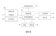
請參閱圖1及圖2所示,本發明提供一種穿刺引導系統,包括一控制裝置10、一機械手臂20、一診斷檢測裝置30、一螢幕40、一腳踏板50、一力感測器60及一暫存器70。控制裝置10具有一影像重建模組11。機械手臂20位於一床80的一第一側,電性連接控制裝置10,具有一手動模式21及一固定模式22,並且安裝一套管90。診斷檢測裝置30位於床80的一第一端,並且電性連接控制裝置10。螢幕40位於床80的第一側,並且電性連接控制裝置10。腳踏板50位於床80的一第二側,電性連接控制裝置10,並且包括一切換鈕51、一第一移動鈕52及一第二移動鈕53。力感測器60設置在機械手臂20上,並且電性連接控制裝置10。暫存器70設置於機械手臂20上,並且電性連接控制裝置10。1 and 2, the present invention provides a puncture guidance system, including a
請參閱圖3至圖14,本發明提供一種穿刺引導方法,包括下列步驟:Referring to Fig. 3 to Fig. 14, the present invention provides a puncture guiding method, which includes the following steps:
步驟S1,如圖3及圖4所示,控制機械手臂20以驅動套管90置於一病患100的身體的一第一位置A,套管90安裝在機械手臂20上。Step S1 , as shown in FIG. 3 and FIG. 4 , controls the
步驟S2,如圖3、圖5至圖7所示,配置診斷檢測裝置30以掃描病患100的身體,而取得套管90及第一位置A附近的組織的多張二維影像31。更明確地說,第一位置A附近的組織包含一目標物200及目標物200周圍的組織。目標物200可以是病患體內任何組織,例如腫瘤。In step S2 , as shown in FIG. 3 , FIG. 5 to FIG. 7 , the
步驟S3,如圖3及圖7所示,根據該等二維影像31建構出一張三維影像111。Step S3 , as shown in FIG. 3 and FIG. 7 , constructs a
步驟S4,如圖3、圖7及圖8,配置一螢幕40以顯示該等二維影像31、三維影像111或其組合。圖8顯示螢幕40右下方為三維影像111,圖8顯示螢幕40左上方、左下方、右上方為二維影像31。在其他實施例中,螢幕40可以單獨顯示二維影像31或三維影像111。Step S4 , as shown in FIG. 3 , FIG. 7 and FIG. 8 , configures a
步驟S5,如圖1及圖3所示,配置腳踏板50,腳踏板50包括切換鈕51、第一移動鈕52及第二移動鈕53。In step S5 , as shown in FIG. 1 and FIG. 3 , the
步驟S6,如圖3及圖9所示,根據切換鈕51的作動,以控制機械手臂20切換成手動模式21或固定模式22。Step S6 , as shown in FIG. 3 and FIG. 9 , controls the
步驟S7,如圖3、圖9至圖12所示,在手動模式21的狀態下,機械手臂20被手動移動以調整套管90的位置至一第二位置B,設定第一位置A與第二位置B之間的路徑為套管90的一移動路徑92,螢幕40顯示機械手臂20和套管90的移動軌跡。Step S7, as shown in FIG. 3, FIG. 9 to FIG. 12, in the state of
步驟S8,如圖3及圖13所示,在固定模式22的狀態下,根據第一移動鈕52的作動,以控制機械手臂20移動而驅動套管90沿著移動路徑92從第二位置B移動到第一位置A,螢幕40顯示機械手臂20和套管90的移動軌跡。Step S8, as shown in FIG. 3 and FIG. 13 , in the state of the fixed
步驟S9,如圖3及圖14所示,在固定模式22的狀態下,根據第二移動鈕53的作動,以控制機械手臂20移動而驅動套管90沿著移動路徑92從第一位置A移動到第二位置B,螢幕40顯示機械手臂20和套管90的移動軌跡。Step S9, as shown in FIG. 3 and FIG. 14 , in the state of the fixed
藉此,本發明能夠藉由腳踏板50操控機械手臂20,套管90的移動較穩定、緩慢且安全,且機械手臂20的移動精度達到毫米等級或更小,套管90得以非常精準地沿著移動路徑92移動到目標位置,絲毫不差。Thereby, the present invention can control the
進一步地說,步驟S1實際上有兩種操作方式。關於第一種操作方式,首先將套管90安裝在機械手臂20上,接著再以腳踩踏切換鈕51,使得機械手臂20切換成手動模式21,此時從業人員能夠手動移動機械手臂20,讓套管90置於病患100的身體的第一位置A。關於第二種操作方式,首先將套管90置於病患100的身體的第一位置A,接著再以腳踩踏切換鈕51,使得機械手臂20切換成手動模式21,此時從業人員能夠手動移動機械手臂20至套管90的一側,最後將套管90安裝在機械手臂20上。Furthermore, step S1 actually has two operation modes. Regarding the first mode of operation, the
如圖1所示,在較佳實施例中,診斷檢測裝置30為一電腦斷層掃描器,電腦斷層掃描器藉由圖像分割算法(例如,直方圖法或水平集方法)感測套管90。因此,所述二維影像31為電腦斷層掃描器產生的二維切片影像,並且以醫療數位影像傳輸協定(DICOM)的格式輸出至影像重建模組11。As shown in FIG. 1 , in a preferred embodiment, the
如圖5至圖7所示,在較佳實施例的步驟S3中,影像重建模組11接收該等二維影像31,根據該等二維影像31界定出套管90與目標物200的空間關係並且建構出三維影像111。如圖4、圖5、圖12及圖14所示,當套管90位於第一位置A時,套管90的一軸線91與目標物200的一軸線210錯開,也就是說,套管90並沒有對準目標物200,因此套管90的位置需要調整。如圖5、圖9、圖12及圖13所示,當套管90位於第二位置B時,套管90的軸線91與目標物200的軸線210對齊,也就是說,套管90已經對準目標物200。As shown in Figures 5 to 7, in step S3 of the preferred embodiment, the
如圖3、圖9至圖12所示,在較佳實施例的步驟S6中,當切換鈕51被作動時,腳踏板50傳送一第一切換訊號501至控制裝置10,控制裝置10根據第一切換訊號501控制機械手臂20切換成手動模式21。如圖3、圖13及圖14所示,在較佳實施例的步驟S6中,當切換鈕51無作動時,腳踏板50傳送一第二切換訊號502至控制裝置10,控制裝置10根據第二切換訊號502控制機械手臂20切換成固定模式22。As shown in Fig. 3, Fig. 9 to Fig. 12, in step S6 of the preferred embodiment, when the
在較佳實施例的步驟S7中,如圖3、圖9及圖12所示,控制裝置10會將第一位置A與第二位置B之間的路徑設定為套管90的移動路徑92,螢幕40顯示機械手臂20和套管90的移動軌跡。In step S7 of the preferred embodiment, as shown in FIG. 3 , FIG. 9 and FIG. 12 , the
在較佳實施例的步驟S8中,如圖3、圖9及圖13所示,在固定模式22的狀態下,當第一移動鈕52被作動且第二移動鈕53無作動時,腳踏板50傳送一第一移動訊號503至控制裝置10,控制裝置10根據第一移動訊號503控制機械手臂20移動,機械手臂20驅動套管90沿著移動路徑92從第二位置B移動到第一位置A,螢幕40顯示機械手臂20和套管90的移動軌跡。In step S8 of the preferred embodiment, as shown in Fig. 3, Fig. 9 and Fig. 13, in the state of the fixed
在較佳實施例的步驟S9中,如圖3、圖11及圖14所示,在固定模式22的狀態下,當第二移動鈕53被作動且第一移動鈕52無作動時,腳踏板50傳送一第二移動訊號504至控制裝置10,控制裝置10根據第二移動訊號504控制機械手臂20移動,機械手臂20驅動套管90沿著移動路徑92從第一位置A移動到第二位置B,螢幕40顯示機械手臂20和套管90的移動軌跡。In step S9 of the preferred embodiment, as shown in Fig. 3, Fig. 11 and Fig. 14, in the state of the fixed
從業人員可以在尚未進行上述方法以前,先將針(圖未示)安裝在套管90上。因此,在步驟S1中,針插入病患100的身體的第一位置A;在步驟S7~9中,針會隨著套管90移動。尤其是,在步驟S9中,在套管90移動到第二位置B以後,針移動至目標物200。A practitioner may install a needle (not shown) on the
從業人員也可以在步驟S9中,在套管90移動到第二位置B以後,先將針(圖未示)安裝在套管90上,再將針插入病患的身體的第二位置B。針移動至目標物200。The practitioner can also install a needle (not shown) on the
藉此,本發明能夠提供一位從業人員操作穿刺、掃描、設定移動路徑92等全部手術流程,同時透過螢幕40觀察機械手臂20和套管90的位置及其移動軌跡,以及腳踩踏腳踏板50操控機械手臂20,還能空出雙手做事,省時省力,操作效率高,節省人力成本。In this way, the present invention can provide a practitioner to operate the entire surgical process such as puncture, scanning, and setting the moving
再者,因為腳踏板50的體積小且放置在地面上,不會影響到從業人員操作,也不占空間,所以適合設置在床80的一側,螢幕40則可設置在床80的另一側。因此,本發明能夠提供一位從業人員站在床80的一側操作手術流程,完全不需要離開床80的一側。Furthermore, because the
如圖15所示,在較佳實施例中,當機械手臂20切換成手動模式21且力感測器60感測到機械手臂20被手動移動時,力感測器60傳送一第一感測訊號61至控制裝置10,控制裝置10根據第一感測訊號61控制機械手臂20能夠被手動移動,讓從業人員能夠任意地移動機械手臂20,以完成步驟S1或步驟S7。是以,本發明能夠藉由腳踏板50和力感測器60的雙重機制啟動機械手臂20,才能夠准許機械手臂20被手動移動,提升操作安全性。As shown in FIG. 15 , in a preferred embodiment, when the
如圖15所示,在較佳實施例中,當機械手臂20切換成固定模式22且力感測器60感測到機械手臂20被外力撞擊時,力感測器60傳送一第二感測訊號62至控制裝置10,控制裝置10根據第二感測訊號62控制機械手臂20停止移動。是以,本發明能夠藉由力感測器60感測機械手臂20是否在固定模式22的狀態下被外力撞擊,並且立刻控制機械手臂20停止移動,防止套管90在偏移後的移動路徑92上移動而造成套管90上的針過度拉扯病患100的傷口。As shown in FIG. 15 , in a preferred embodiment, when the
如圖16所示,在較佳實施例中,當機械手臂20切換成手動模式21時,暫存器70隨時記憶機械手臂20在空間中的即時位置71,控制裝置10根據暫存器70所提供的機械手臂20在空間中的即時位置71重新計算機械手臂20的移動目標位置,以設定套管90的移動路徑92,並且將機械手臂20和套管90的移動軌跡顯示在螢幕40上。是以,本發明能夠藉由暫存器70隨時記憶機械手臂20在空間中的即時位置71,以計算機械手臂20的移動目標位置並設定套管90的移動路徑92,配合螢幕40顯示機械手臂20和套管90的移動軌跡,一位從業人員站在床80的一側以腳踩踏腳踏板50操控機械手臂20的同時,能夠從螢幕40上觀察套管90的位置及移動路徑92是否正確。這樣的操作方式,任何人都能夠輕易地一次就將套管90移動到正確位置,不須反覆修正,操作效率高,更無須額外設置影像擷取裝置和配置另一人輔助操作,節省成本,降低病患的輻射暴露。As shown in FIG. 16 , in a preferred embodiment, when the
在較佳實施例中,在固定模式22的狀態下,機械手臂20的移動速度為每秒0.2~1公分。是以,本發明能夠將機械手臂20在固定模式22的狀態下限制在低速移動,不僅能夠防止套管90上的針折彎或斷裂,還可避免套管90上的針過度拉扯病患100的傷口。In a preferred embodiment, in the state of the fixed
以上所述者僅為用以解釋本發明的較佳實施例,並非企圖據以對本發明做任何形式上的限制,是以,凡有在相同的發明精神下所作有關本發明的任何修飾或變更,皆仍應包括在本發明意圖保護的範疇。The above-mentioned ones are only preferred embodiments for explaining the present invention, and are not intended to limit the present invention in any form. Therefore, any modification or change of the present invention made under the same spirit of the invention , all should still be included in the category that the present invention intends to protect.
10:控制裝置 11:影像重建模組 111:三維影像 20:機械手臂 21:手動模式 22:固定模式 30:診斷檢測裝置 31:二維影像 40:螢幕 50:腳踏板 501:第一切換訊號 502:第二切換訊號 503:第一移動訊號 504:第二移動訊號 51:切換鈕 52:第一移動鈕 53:第二移動鈕 60:力感測器 61:第一感測訊號 62:第二感測訊號 70:暫存器 71:即時位置 80:床 90:套管 91:軸線 92:移動路徑 100:病患 200:目標物 210:軸線 A:第一位置 B:第二位置 S1~S9:步驟10: Control device 11: Image reconstruction group 111: Three-dimensional image 20: Mechanical arm 21: Manual mode 22: fixed mode 30:Diagnostic detection device 31: Two-dimensional image 40: screen 50: Pedal 501: The first switching signal 502: Second switching signal 503: The first mobile signal 504: Second mobile signal 51: switch button 52: The first movement button 53: The second movement button 60: Force sensor 61: The first sensing signal 62: Second sensing signal 70: scratchpad 71: Instant location 80: bed 90: Casing 91: axis 92:Movement path 100: Patient 200: Target 210: axis A: the first position B: second position S1~S9: steps
[圖1〕是本發明的穿刺引導系統的立體圖。 [圖2〕是本發明的穿刺引導系統的方塊圖。 [圖3〕是本發明的穿刺引導方法的流程圖。 [圖4〕是本發明的穿刺引導方法的步驟S1的示意圖。 [圖5〕是本發明的診斷檢測裝置取得單張二維影像的示意圖。 [圖6〕是本發明的診斷檢測裝置取得多張二維影像且影像重建模組界定出套管和目標物的空間關係的示意圖。 [圖7〕是本發明的影像轉換及輸出的方塊圖。 [圖8〕是本發明的螢幕顯示套管及第一位置附近的二維影像和三維影像的示意圖。 [圖9〕是本發明的機械手臂在手動狀態下的操作示意圖。 [圖10〕是本發明的螢幕顯示套管及第二位置附近的二維影像和三維影像的示意圖。 [圖11〕是本發明的腳踏板透過控制裝置操控機械手臂的方塊圖。 [圖12〕是本發明的螢幕顯示機械手臂和套管的移動軌跡的示意圖。 [圖13〕是本發明的機械手臂驅動套管沿著移動路徑從第二位置移動到第一位置的示意圖。 [圖14〕是本發明的機械手臂驅動套管沿著移動路徑從第一位置移動到第二位置的示意圖。 [圖15〕是本發明的力感測器透過控制裝置操控機械手臂的方塊圖。 [圖16〕是本發明的暫存器配合控制裝置設定移動路徑並將移動軌跡顯示於螢幕的方塊圖。[ Fig. 1 ] is a perspective view of the puncture guide system of the present invention. [ Fig. 2 ] is a block diagram of the puncture guidance system of the present invention. [ Fig. 3 ] is a flow chart of the puncture guidance method of the present invention. [ Fig. 4 ] is a schematic diagram of step S1 of the puncture guidance method of the present invention. [ FIG. 5 ] is a schematic diagram of a single two-dimensional image obtained by the diagnostic detection device of the present invention. [ FIG. 6 ] is a schematic diagram of multiple two-dimensional images obtained by the diagnostic detection device of the present invention and the image reconstruction group defining the spatial relationship between the cannula and the target. [FIG. 7] is a block diagram of image conversion and output in the present invention. [ FIG. 8 ] is a schematic diagram of the screen display sleeve and the 2D and 3D images near the first position of the present invention. [Fig. 9] is a schematic diagram of the operation of the mechanical arm of the present invention in the manual state. [ FIG. 10 ] is a schematic diagram of the screen display sleeve and the two-dimensional and three-dimensional images near the second position of the present invention. [FIG. 11] is a block diagram of the pedal controlling the mechanical arm through the control device of the present invention. [FIG. 12] is a schematic diagram of the screen displaying the moving track of the robot arm and the cannula of the present invention. [ Fig. 13 ] is a schematic diagram of the manipulator of the present invention driving the sleeve to move from the second position to the first position along the moving path. [ FIG. 14 ] is a schematic diagram of the manipulator driving the sleeve of the present invention to move from the first position to the second position along the moving path. [ FIG. 15 ] is a block diagram of the force sensor of the present invention controlling the mechanical arm through the control device. [ FIG. 16 ] is a block diagram of the register and the control device of the present invention to set the moving path and display the moving track on the screen.
20:機械手臂20: Mechanical arm
30:診斷檢測裝置30:Diagnostic detection device
40:螢幕40: screen
50:腳踏板50: Pedal
51:切換鈕51: switch button
52:第一移動鈕52: The first movement button
53:第二移動鈕53: The second movement button
80:床80: bed
90:套管90: Casing
Claims (18)
Translated fromChinesePriority Applications (1)
| Application Number | Priority Date | Filing Date | Title |
|---|---|---|---|
| TW110120673ATWI786666B (en) | 2021-06-07 | 2021-06-07 | System and method for puncturing and guiding |
Applications Claiming Priority (1)
| Application Number | Priority Date | Filing Date | Title |
|---|---|---|---|
| TW110120673ATWI786666B (en) | 2021-06-07 | 2021-06-07 | System and method for puncturing and guiding |
Publications (2)
| Publication Number | Publication Date |
|---|---|
| TWI786666Btrue TWI786666B (en) | 2022-12-11 |
| TW202247822A TW202247822A (en) | 2022-12-16 |
Family
ID=85793418
Family Applications (1)
| Application Number | Title | Priority Date | Filing Date |
|---|---|---|---|
| TW110120673ATWI786666B (en) | 2021-06-07 | 2021-06-07 | System and method for puncturing and guiding |
Country Status (1)
| Country | Link |
|---|---|
| TW (1) | TWI786666B (en) |
Citations (5)
| Publication number | Priority date | Publication date | Assignee | Title |
|---|---|---|---|---|
| US20110060216A1 (en)* | 2003-10-16 | 2011-03-10 | Medtronic Navigation, Inc | Method and Apparatus for Surgical Navigation of a Multiple Piece Construct for Implantation |
| US20130190741A1 (en)* | 2006-08-03 | 2013-07-25 | Hansen Medical, Inc. | Systems and methods for performing minimally invasive procedures |
| TW201801682A (en)* | 2016-07-11 | 2018-01-16 | 王民良 | An image guided augmented reality method and a surgical navigation of wearable glasses using the same |
| TW201822724A (en)* | 2016-12-21 | 2018-07-01 | 財團法人工業技術研究院 | Needle guide system and medical intervention system |
| CN112220557A (en)* | 2019-06-30 | 2021-01-15 | 苏州理禾医疗技术有限公司 | Operation navigation and robot arm device for craniocerebral puncture and positioning method |
- 2021
- 2021-06-07TWTW110120673Apatent/TWI786666B/enactive
Patent Citations (5)
| Publication number | Priority date | Publication date | Assignee | Title |
|---|---|---|---|---|
| US20110060216A1 (en)* | 2003-10-16 | 2011-03-10 | Medtronic Navigation, Inc | Method and Apparatus for Surgical Navigation of a Multiple Piece Construct for Implantation |
| US20130190741A1 (en)* | 2006-08-03 | 2013-07-25 | Hansen Medical, Inc. | Systems and methods for performing minimally invasive procedures |
| TW201801682A (en)* | 2016-07-11 | 2018-01-16 | 王民良 | An image guided augmented reality method and a surgical navigation of wearable glasses using the same |
| TW201822724A (en)* | 2016-12-21 | 2018-07-01 | 財團法人工業技術研究院 | Needle guide system and medical intervention system |
| CN112220557A (en)* | 2019-06-30 | 2021-01-15 | 苏州理禾医疗技术有限公司 | Operation navigation and robot arm device for craniocerebral puncture and positioning method |
Also Published As
| Publication number | Publication date |
|---|---|
| TW202247822A (en) | 2022-12-16 |
Similar Documents
| Publication | Publication Date | Title |
|---|---|---|
| KR102643758B1 (en) | Biopsy devices and systems | |
| US11529070B2 (en) | System and methods for guiding a medical instrument | |
| KR102802204B1 (en) | Systems and methods for simultaneous medical procedures | |
| KR101612278B1 (en) | Location system with virtual touch screen | |
| US20230233269A1 (en) | System for controlling ablation treatment and visualization | |
| CN110234274B (en) | Methods and systems for real-time planning and monitoring of ablation needle deployment in tissue | |
| KR102327948B1 (en) | Structural adjustment systems and methods for a teleoperational medical system | |
| US7632265B2 (en) | Radio frequency ablation servo catheter and method | |
| CN101918073B (en) | Remotely controlled catheter insertion system | |
| WO2019107226A1 (en) | Endoscopic apparatus | |
| CN117204928A (en) | 3D imaging technology intelligently guides clinical puncture equipment | |
| TWI786666B (en) | System and method for puncturing and guiding | |
| CN118510462A (en) | Off-screen indicator viewer UI | |
| US20240415587A1 (en) | Puncture guiding system and method | |
| JP2019097665A (en) | Endoscope apparatus | |
| JP2006519629A (en) | Remote control of medical devices using virtual device interfaces | |
| US20250195154A1 (en) | User interface for surgical robotic system | |
| US20250195153A1 (en) | User interface for surgical robotic system | |
| US20250195167A1 (en) | Ergonomic surgical robotic system | |
| US20240335185A1 (en) | Processing apparatus and control method | |
| JPH08173411A (en) | Controller for image diagnostic system | |
| CN116999168A (en) | surgical operating system |