TWI783277B - Connector - Google Patents
ConnectorDownload PDFInfo
- Publication number
- TWI783277B TWI783277BTW109135416ATW109135416ATWI783277BTW I783277 BTWI783277 BTW I783277BTW 109135416 ATW109135416 ATW 109135416ATW 109135416 ATW109135416 ATW 109135416ATW I783277 BTWI783277 BTW I783277B
- Authority
- TW
- Taiwan
- Prior art keywords
- insulator
- connector
- contact
- fitting
- axial direction
- Prior art date
Links
- 239000012212insulatorSubstances0.000claimsabstractdescription205
- 239000013013elastic materialSubstances0.000claimsabstractdescription9
- 210000000078clawAnatomy0.000claimsdescription36
- 230000000149penetrating effectEffects0.000claimsdescription9
- 230000035515penetrationEffects0.000claimsdescription3
- 230000005540biological transmissionEffects0.000abstractdescription20
- 230000006866deteriorationEffects0.000abstractdescription10
- 230000002349favourable effectEffects0.000abstract1
- 230000000052comparative effectEffects0.000description12
- 238000011084recoveryMethods0.000description6
- 239000004020conductorSubstances0.000description5
- 238000005259measurementMethods0.000description5
- 230000005489elastic deformationEffects0.000description4
- 239000000463materialSubstances0.000description4
- 230000013011matingEffects0.000description4
- 230000000694effectsEffects0.000description3
- 229920002379silicone rubberPolymers0.000description3
- 230000015572biosynthetic processEffects0.000description2
- 238000006073displacement reactionMethods0.000description2
- 239000011810insulating materialSubstances0.000description2
- 238000000465mouldingMethods0.000description2
- 239000000853adhesiveSubstances0.000description1
- 230000001070adhesive effectEffects0.000description1
- 230000004323axial lengthEffects0.000description1
- 230000002542deteriorative effectEffects0.000description1
- 238000001746injection mouldingMethods0.000description1
- 238000003780insertionMethods0.000description1
- 230000037431insertionEffects0.000description1
- 239000007788liquidSubstances0.000description1
- 238000005192partitionMethods0.000description1
- 230000002093peripheral effectEffects0.000description1
- 229920000515polycarbonatePolymers0.000description1
- 239000004417polycarbonateSubstances0.000description1
- 229920005989resinPolymers0.000description1
- 239000011347resinSubstances0.000description1
- 230000008054signal transmissionEffects0.000description1
- 239000004945silicone rubberSubstances0.000description1
- 239000000758substrateSubstances0.000description1
- 229920003002synthetic resinPolymers0.000description1
- 239000000057synthetic resinSubstances0.000description1
Images


Classifications
- H—ELECTRICITY
- H01—ELECTRIC ELEMENTS
- H01R—ELECTRICALLY-CONDUCTIVE CONNECTIONS; STRUCTURAL ASSOCIATIONS OF A PLURALITY OF MUTUALLY-INSULATED ELECTRICAL CONNECTING ELEMENTS; COUPLING DEVICES; CURRENT COLLECTORS
- H01R24/00—Two-part coupling devices, or either of their cooperating parts, characterised by their overall structure
- H01R24/38—Two-part coupling devices, or either of their cooperating parts, characterised by their overall structure having concentrically or coaxially arranged contacts
- H01R24/40—Two-part coupling devices, or either of their cooperating parts, characterised by their overall structure having concentrically or coaxially arranged contacts specially adapted for high frequency
- H—ELECTRICITY
- H01—ELECTRIC ELEMENTS
- H01R—ELECTRICALLY-CONDUCTIVE CONNECTIONS; STRUCTURAL ASSOCIATIONS OF A PLURALITY OF MUTUALLY-INSULATED ELECTRICAL CONNECTING ELEMENTS; COUPLING DEVICES; CURRENT COLLECTORS
- H01R24/00—Two-part coupling devices, or either of their cooperating parts, characterised by their overall structure
- H01R24/38—Two-part coupling devices, or either of their cooperating parts, characterised by their overall structure having concentrically or coaxially arranged contacts
- H01R24/40—Two-part coupling devices, or either of their cooperating parts, characterised by their overall structure having concentrically or coaxially arranged contacts specially adapted for high frequency
- H01R24/42—Two-part coupling devices, or either of their cooperating parts, characterised by their overall structure having concentrically or coaxially arranged contacts specially adapted for high frequency comprising impedance matching means or electrical components, e.g. filters or switches
- H01R24/44—Two-part coupling devices, or either of their cooperating parts, characterised by their overall structure having concentrically or coaxially arranged contacts specially adapted for high frequency comprising impedance matching means or electrical components, e.g. filters or switches comprising impedance matching means
- H—ELECTRICITY
- H01—ELECTRIC ELEMENTS
- H01R—ELECTRICALLY-CONDUCTIVE CONNECTIONS; STRUCTURAL ASSOCIATIONS OF A PLURALITY OF MUTUALLY-INSULATED ELECTRICAL CONNECTING ELEMENTS; COUPLING DEVICES; CURRENT COLLECTORS
- H01R13/00—Details of coupling devices of the kinds covered by groups H01R12/70 or H01R24/00 - H01R33/00
- H01R13/46—Bases; Cases
- H01R13/52—Dustproof, splashproof, drip-proof, waterproof, or flameproof cases
- H01R13/5205—Sealing means between cable and housing, e.g. grommet
- H—ELECTRICITY
- H01—ELECTRIC ELEMENTS
- H01R—ELECTRICALLY-CONDUCTIVE CONNECTIONS; STRUCTURAL ASSOCIATIONS OF A PLURALITY OF MUTUALLY-INSULATED ELECTRICAL CONNECTING ELEMENTS; COUPLING DEVICES; CURRENT COLLECTORS
- H01R13/00—Details of coupling devices of the kinds covered by groups H01R12/70 or H01R24/00 - H01R33/00
- H01R13/02—Contact members
- H01R13/04—Pins or blades for co-operation with sockets
- H01R13/05—Resilient pins or blades
- H01R13/052—Resilient pins or blades co-operating with sockets having a circular transverse section
- H—ELECTRICITY
- H01—ELECTRIC ELEMENTS
- H01R—ELECTRICALLY-CONDUCTIVE CONNECTIONS; STRUCTURAL ASSOCIATIONS OF A PLURALITY OF MUTUALLY-INSULATED ELECTRICAL CONNECTING ELEMENTS; COUPLING DEVICES; CURRENT COLLECTORS
- H01R13/00—Details of coupling devices of the kinds covered by groups H01R12/70 or H01R24/00 - H01R33/00
- H01R13/02—Contact members
- H01R13/22—Contacts for co-operating by abutting
- H01R13/24—Contacts for co-operating by abutting resilient; resiliently-mounted
- H01R13/2407—Contacts for co-operating by abutting resilient; resiliently-mounted characterized by the resilient means
- H—ELECTRICITY
- H01—ELECTRIC ELEMENTS
- H01R—ELECTRICALLY-CONDUCTIVE CONNECTIONS; STRUCTURAL ASSOCIATIONS OF A PLURALITY OF MUTUALLY-INSULATED ELECTRICAL CONNECTING ELEMENTS; COUPLING DEVICES; CURRENT COLLECTORS
- H01R13/00—Details of coupling devices of the kinds covered by groups H01R12/70 or H01R24/00 - H01R33/00
- H01R13/46—Bases; Cases
- H01R13/516—Means for holding or embracing insulating body, e.g. casing, hoods
- H—ELECTRICITY
- H01—ELECTRIC ELEMENTS
- H01R—ELECTRICALLY-CONDUCTIVE CONNECTIONS; STRUCTURAL ASSOCIATIONS OF A PLURALITY OF MUTUALLY-INSULATED ELECTRICAL CONNECTING ELEMENTS; COUPLING DEVICES; CURRENT COLLECTORS
- H01R13/00—Details of coupling devices of the kinds covered by groups H01R12/70 or H01R24/00 - H01R33/00
- H01R13/646—Details of coupling devices of the kinds covered by groups H01R12/70 or H01R24/00 - H01R33/00 specially adapted for high-frequency, e.g. structures providing an impedance match or phase match
- H01R13/6473—Impedance matching
- H01R13/6477—Impedance matching by variation of dielectric properties
- H—ELECTRICITY
- H01—ELECTRIC ELEMENTS
- H01R—ELECTRICALLY-CONDUCTIVE CONNECTIONS; STRUCTURAL ASSOCIATIONS OF A PLURALITY OF MUTUALLY-INSULATED ELECTRICAL CONNECTING ELEMENTS; COUPLING DEVICES; CURRENT COLLECTORS
- H01R2103/00—Two poles
Landscapes
- Coupling Device And Connection With Printed Circuit (AREA)
- Details Of Connecting Devices For Male And Female Coupling (AREA)
- Mechanical Coupling Of Light Guides (AREA)
- Surgical Instruments (AREA)
Abstract
Description
Translated fromChinese本發明關於連接器,特別關於具有構成傳輸路徑的內外的配線以及這些配線之間的絕緣體的連接器。The present invention relates to a connector, and more particularly to a connector having internal and external wiring constituting a transmission path and an insulator between these wirings.
在中心導體與外部導體之間設置有絕緣體的同軸線纜等的傳輸路徑中,作為信號線的中心導體的電感和導體之間的電容(靜電電容)按每單位長度是恆定的且信號的傳輸特性優異,傳輸路徑的特性阻抗Z[Ω]被設定為與每單位長度的電感L[H]以及電容C[F]的值相對應的規定值。In a transmission path such as a coaxial cable in which an insulator is provided between a central conductor and an outer conductor, the inductance of the central conductor as a signal line and the capacitance (electrostatic capacitance) between conductors are constant per unit length and the transmission of signals The characteristics are excellent, and the characteristic impedance Z [Ω] of the transmission path is set to a predetermined value corresponding to the value of the inductance L [H] and the capacitance C [F] per unit length.
另外,在將傳輸路徑連接到其他設備種類的情況下,當未取得使傳輸路徑的特性阻抗與設備側的基準阻抗一致的阻抗匹配時,產生諸如信號在特性阻抗不同的傳輸路徑的邊界點反射,波形失真之類的影響。In addition, when the transmission path is connected to other types of equipment, if impedance matching is not obtained so that the characteristic impedance of the transmission path matches the reference impedance on the equipment side, such as signal reflection at the boundary point of the transmission path with different characteristic impedance occurs. , effects such as waveform distortion.
因此,在將傳輸路徑連接到其他設備種類的連接器中,需要避免反射所致的特性阻抗變差。Therefore, in connectors that connect transmission paths to other types of devices, it is necessary to avoid deterioration of characteristic impedance due to reflection.
作為以往的這種連接器,在專利文獻1中,記載了如下的連接器:其著眼於在公母連接器部件中在徑向上相對置的內外接觸件的相對置面積越大且距離越小、或兩個接觸件之間的絕緣體的電容率越高,則靜電容量越大這一點,為了調整特性阻抗(Z=(L/C)1/2),將公側的插銷接觸件部分設為高阻抗區間,以能夠補償母側的插口連接器(socket connector)部分的低阻抗,從而獲得良好的傳輸特性(參照該公報的第0031段、第0085~0086段等)。As a conventional connector of this type,
[先前技術文獻][Prior Art Literature]
[專利文獻][Patent Document]
專利文獻1:日本特許第3653029號公報Patent Document 1: Japanese Patent No. 3653029
然而,在如上前述的以往的連接器中,當在公母嵌合的嵌合部產生各部件的尺寸的偏差和嵌合的角度的偏差等時,在公母連接器的絕緣體彼此的相對置面之間產生間隙,由此因絕緣體層的中斷所致的電容率的變化而在沿著傳輸路徑恆定地設定的特性阻抗中發生不匹配,傳輸特性有可能變差。However, in the above-mentioned conventional connectors, when the size deviation of each component and the deviation of the fitting angle occur in the fitting part of the male and female fittings, the insulators of the male and female connectors face each other. A gap is generated between the planes, and as a result, a mismatch occurs in the characteristic impedance set constantly along the transmission path due to a change in the permittivity due to the interruption of the insulator layer, and the transmission characteristic may deteriorate.
因此,本發明的目的在於提供一種能夠有效地抑制嵌合部中的特性阻抗變差並獲得良好的傳輸特性的連接器。Therefore, an object of the present invention is to provide a connector capable of effectively suppressing deterioration of characteristic impedance in a fitting portion and obtaining good transmission characteristics.
(1)為了達成上述目的,本發明的連接器具備:內部接觸件,在軸線方向上延伸並且位於徑向的內側;外部接觸件,在前述軸線方向上延伸並且位於前述徑向的外側;以及絕緣體,位於前述內部接觸件與前述外部接觸件之間,前述內部接觸件與前述外部接觸件中至少一者在前述軸線方向的一側具有以既定的徑向接觸壓力嵌合於相對應的對象側接觸件的嵌合部,其特徵在於,前述絕緣體具有:第一絕緣體部,露出在前述軸線方向的一側;以及第二絕緣體部,相對於前述第一絕緣體部位於前述軸線方向的另一側,前述第一絕緣體部由與前述第二絕緣體部相比容易在前述徑向上彈性變形的彈性材料形成。(1) In order to achieve the above object, the connector of the present invention has: an inner contact extending in the axial direction and located radially inward; an outer contact extending in the aforementioned axial direction and located radially outer; and The insulator is located between the inner contact and the outer contact, at least one of the inner contact and the outer contact has a function on one side in the axial direction that fits with a corresponding object with a predetermined radial contact pressure. A fitting portion of a side contact, wherein the insulator has: a first insulator portion exposed on one side in the axial direction; and a second insulator portion located on the other side in the axial direction relative to the first insulator portion. On the other hand, the first insulator portion is formed of an elastic material that is more easily elastically deformed in the radial direction than the second insulator portion.
根據該構成,在本發明中,在內部接觸件以及外部接觸件中至少一者的嵌合部以既定的徑向接觸壓力嵌合於相對應的對象側接觸件時,位於軸線方向的一側的第一絕緣體部能夠容易地彈性變形。因此,用於嵌合部之與對象側接觸件的嵌合的彈性變形和彈性復原變容易,並且能夠有效地抑制在彈性復原之後的絕緣體與內部接觸件以及外部接觸件之間產生間隙,能夠有效地抑制特性阻抗因間隙空間的產生所致的電容率變化而變差。According to this configuration, in the present invention, when the fitting portion of at least one of the inner contact and the outer contact is fitted to the corresponding mating contact with a predetermined radial contact pressure, it is positioned on one side in the axial direction. The first insulator portion can be easily elastically deformed. Therefore, the elastic deformation and elastic recovery for the fitting of the mating portion with the contact on the mating side become easy, and it is possible to effectively suppress the occurrence of gaps between the insulator after elastic recovery, the internal contact and the external contact, and it is possible to Effectively suppresses characteristic impedance from deteriorating due to changes in permittivity due to generation of interstitial spaces.
(2)在本發明中也可以構成為,前述嵌合部具有位於前述軸線方向的一側的大致分割筒狀的多個嵌合爪部分、以及將該多個嵌合爪部分以多個狹縫隔開並一體地懸臂支持的支持筒部分,前述第一絕緣體部配置在與前述支持筒部分相比靠前述軸線方向的一側的範圍內。(2) In the present invention, the fitting portion may have a plurality of substantially divided cylindrical fitting claw portions located on one side in the axial direction, and the plurality of fitting claw portions may be formed in a plurality of narrow rows. The supporting cylinder part is separated by a slit and integrally supported by a cantilever, and the first insulator part is disposed within a range on one side in the axial direction of the supporting cylinder part.
在以這種構成實施時,在嵌合部嵌合時,多個嵌合爪部分在徑向上翹曲並壓縮第一絕緣體部,或者與第一絕緣體部一起彈性復原。因此,能夠使嵌合操作變容易,並且能夠更加有效地抑制在絕緣體與內部接觸件或者外部接觸件之間產生間隙空間。When implemented in such a configuration, when the fitting portions are fitted, the plurality of fitting claw portions warp in the radial direction and compress the first insulator portion, or elastically return together with the first insulator portion. Therefore, the fitting operation can be facilitated, and the generation of a gap space between the insulator and the internal contact or the external contact can be more effectively suppressed.
(3)在本發明中也可以構成為,前述多個狹縫各自的寬度在被前述支持筒部分支持的前述多個嵌合爪部分的基端側較大,在前述多個嵌合爪部分的頂端側較小。(3) In the present invention, the respective widths of the plurality of slits may be larger on the base end side of the plurality of fitting claw portions supported by the support cylinder portion, and the width of each of the plurality of fitting claw portions may be larger. The top side is smaller.
在以這種構成實施時,不在多個嵌合爪部分形成如產生應力集中的孔等,就能夠確保多個嵌合爪部分所需的翹曲量以及強度,並且能夠藉由加寬狹縫寬度來進一步使第一絕緣體部的徑向的彈性變形變容易,能夠更加有效地抑制在絕緣體與內部以及外部接觸件之間形成間隙空間。另外,能夠更加有效地抑制在第二絕緣體部側施加載荷。When implemented in this configuration, the amount of warpage and strength required for the plurality of fitting claws can be ensured without forming holes where stress concentration occurs in the plurality of fitting claws, and by widening the slit The radial elastic deformation of the first insulator part can be further facilitated by increasing the width, and the formation of gap spaces between the insulator and the internal and external contacts can be more effectively suppressed. In addition, it is possible to more effectively suppress the application of a load on the second insulator portion side.
(4)在本發明中也可以構成為,前述第一絕緣體部的一端面與前述外部接觸件或者前述內部接觸件相比向前述軸線方向的一側突出,前述內部接觸件具有:貫穿部,貫穿前述絕緣體;突出端部,與前述第一絕緣體部相比向前述軸線方向的一側突出;以及突起部,從前述貫穿部向前述第一絕緣體部在徑向上突起。(4) In the present invention, one end surface of the first insulator portion may protrude to one side in the axial direction than the external contact or the internal contact, and the internal contact may have a penetration portion, The insulator is penetrated; a protruding end protrudes to one side in the axial direction than the first insulator portion; and a protrusion protrudes radially from the penetrating portion toward the first insulator portion.
這樣,即使第一絕緣體部彈性地抵接於對象側,也藉由內部接觸件的突起部來限制第一絕緣體部的軸線方向移位,不會在抵接部分產生間隙,而且,也不會有大的載荷施加在第二絕緣體部側。In this way, even if the first insulator part is elastically abutted against the opposite side, the axial displacement of the first insulator part is restricted by the protrusion of the inner contact, and no gap is generated at the abutting part. A large load is applied to the second insulator portion side.
(5)在本發明中也可以構成為,前述第一絕緣體部具有與前述第二絕緣體部同等的相對介電係數。(5) In the present invention, the first insulator portion may have a relative permittivity equal to that of the second insulator portion.
在這種情況下,能夠有效地抑制特性阻抗在嵌合部變差。In this case, it is possible to effectively suppress deterioration of the characteristic impedance at the fitting portion.
(6)在本發明中也可以構成為,第一絕緣體部與前述第二絕緣體部結合為一體。(6) In the present invention, the first insulator portion and the second insulator portion may be integrally integrated.
這樣,能夠以穩定的位置以及態勢配置第一絕緣體部,以免在絕緣體部分產生間隙。In this way, the first insulator portion can be arranged in a stable position and posture without creating a gap in the insulator portion.
(7)本發明的連接器也可以構成為,公母連接器部件分別具備:內部接觸件,在軸線方向上延伸並且位於徑向的內側;外部接觸件,在前述軸線方向上延伸並且位於前述徑向的外側;以及絕緣體,位於前述內部接觸件與前述外部接觸件之間,前述公母連接器部件中公側的連接器部件具有分別以既定的徑向接觸壓力嵌合於相對應的對象側接觸件的第一公側嵌合部以及第二公側嵌合部,並且,前述公母連接器部件中母側的連接器部件具有分別以既定的徑向接觸壓力嵌合於相對應的對象側接觸件的第一母側嵌合部以及第二母側嵌合部,其特徵在於,前述公側的連接器部件的絕緣體具有:第一絕緣體部,露出在前述軸線方向的一側;以及第二絕緣體部,相對於前述第一絕緣體部位於前述軸線方向的另一側,前述第一絕緣體部由與前述第二絕緣體部相比容易在前述徑向上彈性變形的彈性材料形成。(7) The connector of the present invention may be configured such that the male and female connector parts respectively include: an inner contact extending in the axial direction and located radially inside; an outer contact extending in the axial direction and located in the aforementioned radially outside; and an insulator located between the aforementioned inner contact and the aforementioned outer contact, the connector parts on the male side of the aforementioned male and female connector parts having a predetermined radial contact pressure respectively fitted to the corresponding counterpart side The first male-side fitting part and the second male-side fitting part of the contact piece, and the connector parts on the female side of the aforementioned male and female connector parts have a function of being fitted to the corresponding object with a predetermined radial contact pressure, respectively. The first female-side fitting part and the second female-side fitting part of the side contact are characterized inIn that, the insulator of the connector part on the male side has: a first insulator part exposed on one side of the aforementioned axial direction; and a second insulator part located on the other side of the aforementioned axial direction relative to the aforementioned first insulator part. The first insulator portion is formed of an elastic material that is more easily elastically deformed in the aforementioned radial direction than the aforementioned second insulator portion.
當採用該構成時,在公母連接器部件嵌合時,公側連接器部件的第一絕緣體部能夠容易地彈性變形,因此用於母側連接器與相對應的對象側接觸件嵌合的彈性變形和彈性復原變容易,並且能夠有效地抑制在絕緣體與內部以及外部接觸件之間產生間隙,能夠抑制特性阻抗因間隙空間的產生所致的電容率變化而變差。When this structure is adopted, when the male and female connector parts are mated, the first insulator part of the male side connector part can be easily elastically deformed, so it is used for fitting the female side connector with the corresponding mating side contact. Elastic deformation and elastic recovery are facilitated, and the generation of gaps between the insulator and the internal and external contacts can be effectively suppressed, and deterioration of the characteristic impedance due to changes in permittivity due to the generation of gap spaces can be suppressed.
(8)在本發明中也可以構成為,前述公側的連接器部件的前述第一絕緣體部的一端與前述公側的連接器部件的前述外部接觸件相比向前述軸線方向的一側突出。(8) In the present invention, one end of the first insulator portion of the male-side connector member may protrude to one side in the axial direction than the external contact of the male-side connector member. .
在這種情況下,公側連接器部件的第一絕緣體部的一端比外部接觸件更早地壓接於母側連接器的絕緣體,由此不僅在徑向上,而且在軸線方向上,公母連接器部件的絕緣體也藉由第一絕緣體部來無間隙地配置為連接狀態。In this case, one end of the first insulator portion of the male-side connector part is crimped to the insulator of the female-side connector earlier than the external contact, whereby the male-female connector is not only radially but also axially The insulators of the connector member are also arranged in a connected state without gaps by the first insulator portion.
(9)在本發明中也可以構成為,前述公側的連接器部件的前述內部接觸件與前述公側的連接器部件的前述第一絕緣體部以及前述外部接觸件相比向前述軸線方向的一側突出地構成前述第一公側嵌合部,並且,前述母側的連接器部件的前述內部接觸件具有前述軸線方向上的長度大於等於前述第一公側嵌合部的第一母側嵌合部。(9) In the present invention, the inner contact of the male-side connector part may be arranged in a direction opposite to the axial direction of the first insulator part and the outer contact of the male-side connector part. One side protrudes to form the first male-side fitting portion, and the female-side connector partThe aforementioned internal contact piece has a first female-side fitting portion whose length in the axial direction is greater than or equal to the aforementioned first male-side fitting portion.
當採用這種構成時,能夠穩定確保公母連接器部件的嵌合狀態中的第一絕緣體部的形狀以及態勢,並且能夠穩定確保兩個連接器部件的內部接觸件彼此、以及外部接觸件彼此的接觸。When this configuration is adopted, the shape and posture of the first insulator portion in the mated state of the male and female connector parts can be stably ensured, and the internal contacts and the external contacts of the two connector parts can be stably secured. s contact.
根據本發明,能夠有效地抑制電容因連接器的嵌合部中的絕緣體的壓扁和/或退讓而變化,傳輸路徑的特性阻抗變差。According to the present invention, it is possible to effectively suppress a change in capacitance due to crushing and/or retreat of the insulator in the fitting portion of the connector, and deterioration of the characteristic impedance of the transmission path.
1:連接器1: connector
10:插頭(公側的連接器部件)10: Plug (connector part on the male side)
11:內部接觸件11: Internal contacts
11a:貫穿部11a: Penetrating part
11b:第一公側嵌合部(嵌合部)11b: The first male-side fitting part (fitting part)
11c:臺階部11c: step part
11d:突起部11d: protrusion
12:外部接觸件12: External contact
12a:嵌合爪部分12a: Fitting claw part
12b:支持筒部分12b: Support cylinder part
12c,12e:狹縫12c, 12e: slit
12d:突起部12d: protrusion
12f:第二公側嵌合部(嵌合部)12f: second male side fitting part (fitting part)
13:絕緣體(插頭側的絕緣體)13: Insulator (insulator on the plug side)
20:插座(母側的連接器部件)20: Receptacle (connector part on the female side)
21:內部接觸件(對象側接觸件)21: Internal contact (object side contact)
21b:第一母側嵌合部21b: the first female side fitting part
22:外部接觸件(對象側接觸件)22: External contact (object side contact)
22f:第二母側嵌合部22f: second female side fitting part
23:絕緣體(插座側的絕緣體)23: Insulator (insulator on the socket side)
23a:端面23a: end face
31:第一絕緣體部31: The first insulator part
31a:一端面31a: one end face
31b:中心孔31b: Center hole
31c:內突部31c: inner protrusion
32:第二絕緣體部32: Second insulator part
w,w1,w2:寬度w, w1, w2: width
圖1是本發明的第一實施方式之連接器的主要部分縱剖視圖。Fig. 1 is a longitudinal sectional view of main parts of a connector according to a first embodiment of the present invention.
圖2是本發明的第一實施方式之連接器中的插頭側的主要部分立體圖。2 is a perspective view of main parts on the plug side in the connector according to the first embodiment of the present invention.
圖3中的(a)是本發明的第一實施方式之連接器中的插頭側的主要部分的側視圖,(b)是圖3中的(a)中的B3-B3箭視剖視圖,(c)是圖3中的(b)中的C3箭視圖。(a) in FIG. 3 is a side view of the main part of the plug side in the connector of the first embodiment of the present invention, (b) is a cross-sectional view of B3-B3 arrow in (a) in FIG. 3 , ( c) is a view of arrow C3 in (b) in FIG. 3 .
圖4中的(a)是本發明的第一實施方式之連接器中的插頭側的外部接觸件的主要部分縱剖視圖,(b)是該外部接觸件的主要部分立體圖。4( a ) is a longitudinal sectional view of main parts of the external contact on the plug side in the connector according to the first embodiment of the present invention, and (b) is a perspective view of main parts of the external contact.
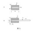
圖5中的(a)是本發明的第一實施方式之連接器中的插頭側的第一絕緣體部的縱剖視圖,(b)是示出第一實施方式之連接器中的、將插頭側的內部接觸件插入到第一絕緣體部的狀態的剖視圖。(a) in FIG. 5 is a vertical cross-sectional view of the first insulator part on the plug side in the connector according to the first embodiment of the present invention, and (b) shows the first insulator part on the plug side in the connector according to the first embodiment. A cross-sectional view of a state in which the internal contact is inserted into the first insulator portion.
圖6中的(a)是本發明的第一實施方式之連接器中的插座側的主要部分縱剖視圖,(b)是該插座側的嵌合部中的內部接觸件的立體圖,(c)是該插座側的絕緣體的立體圖。(a) in FIG. 6 is a longitudinal sectional view of main parts on the socket side in the connector according to the first embodiment of the present invention, (b) is a perspective view of an internal contact in a fitting portion on the socket side, and (c) It is a perspective view of the insulator on the socket side.
圖7是以能夠與不設置如第一絕緣體部那樣的彈性材料的比較例進行比較的方式示出對具有本發明的第一實施方式之連接器的構成的實施例1的連接器進行了時域反射率測定的結果的圖表,縱軸表示阻抗,橫軸表示於測定物件要素導致的信號延遲量所對應的延遲時間。FIG. 7 shows when the connector of Example 1 having the configuration of the connector of the first embodiment of the present invention can be compared with a comparative example in which an elastic material such as the first insulator part is not provided. In the graph of the results of domain reflectance measurement, the vertical axis represents the impedance, and the horizontal axis represents the delay time corresponding to the amount of signal delay caused by the measurement object element.
圖8是本發明的第二實施方式之連接器的主要部分縱剖視圖。Fig. 8 is a longitudinal sectional view of main parts of a connector according to a second embodiment of the present invention.
圖9中的(a)是本發明的第二實施方式之連接器中的插頭側的主要部分縱剖視圖,(b)是該插頭側的主要部分的側視圖,(c)是該主要部分的立體圖。(a) in FIG. 9 is a longitudinal sectional view of main parts on the plug side in the connector according to the second embodiment of the present invention, (b) is a side view of main parts on the plug side, and (c) is a view of the main parts. stereogram.
圖10是本發明的第三實施方式之連接器的主要部分縱剖視圖。Fig. 10 is a longitudinal sectional view of main parts of a connector according to a third embodiment of the present invention.
圖11中的(a)是本發明的第三實施方式之連接器中的內部接觸件的側視圖,(b)是第三實施方式之連接器中的內部接觸件的主要部分立體圖。(a) in FIG. 11 is a side view of the inner contact in the connector of the third embodiment of the present invention, and (b) is a perspective view of main parts of the inner contact in the connector of the third embodiment.
圖12是以能夠與比較例以及第一實施方式進行比較的方式示出本發明的第三實施方式之連接器中的時域反射率的測定結果的圖表,縱軸表示阻抗,橫軸表示基於測定物件要素的信號延遲量所對應的延遲時間。12 is a graph showing the measurement results of the time-domain reflectance in the connector of the third embodiment of the present invention in a manner that can be compared with the comparative example and the first embodiment. The vertical axis represents impedance, and the horizontal axis represents the impedance based on Measure the delay time corresponding to the signal delay amount of the object element.
[實施發明之較佳形態][Preferable Mode for Carrying Out the Invention]
以下,參照附圖,對用於實施本發明的方式進行說明。Hereinafter, modes for implementing the present invention will be described with reference to the drawings.
(第一實施方式)(first embodiment)
圖1至圖6示出本發明的第一實施方式之連接器。1 to 6 show a connector according to a first embodiment of the present invention.
首先,對構成進行說明。First, the configuration will be described.
如圖1所示,本實施方式的連接器1中,作為公母連接器部件的插頭10以及插座20分別在作為圖1的左右方向的軸線方向上延伸,能夠在各自的連接端側以外殼嵌合深度Lf的凹凸嵌合狀態使插頭10卡合於作為母側的連接器部件的插座20,或者以非嵌合狀態從插座20脫離。As shown in FIG. 1, in the
此外,本實施方式的連接器1在公母連接器部件的嵌合部的構造上具有特徵,不特別限定作為同軸連接器和同軸插頭等連接、安裝在其他的設備和基板、線纜等的端部(圖1中的插頭10的右端部以及插座20的左端部)的構造,能夠採用以往已知的任意的連接、安裝構造。因此,在此,省略向同軸線纜和設備側的連接構造的詳細的說明和圖示,但能夠應用向例如公知的印刷電路板的安裝構造(例如參照日本特開2017-41347號公報)、同軸線纜與設備基板之間的連接構造(例如參照日本特開2006-344491號公報)、面安裝構造(例如參照日本特開2009-16178號公報)、天線的外部連接構造(例如參照日本特開2014-138375號公報)、向精密設備的連接構成(例如參照日本特開2015-225766號公報)等。In addition, the
如圖2以及圖3所示,作為公側的連接器部件的插頭10具備:內部接觸件11,位於徑向的內側;呈筒狀的外殼形狀的外部接觸件12,在軸線方向上延伸並且位於徑向的外側;以及厚壁的筒狀的絕緣體13,位於內部接觸件11以及外部接觸件12之間。As shown in FIGS. 2 and 3 , the
如圖3以及圖5所示,插頭10的內部接觸件11一體地具有由線材狀的導體構成並且貫穿絕緣體13的中心的大致圓形截面的貫穿部11a、以及形成為直徑比該貫穿部11a小並且比絕緣體13向軸線方向一側(圖1中的左側)突出的第一公側嵌合部11b(突出端部),第一公側嵌合部11b的頂端呈大致圓錐形狀。在此,內部接觸件11比外部接觸件12向軸線方向一側突出,第一絕緣體部31的一端面31a在插頭10向插座20嵌合時的插入方向上(以下,簡稱為嵌合方向)位於內部接觸件11的頂端與外部接觸件12的頂端之間。As shown in FIGS. 3 and 5 , the
如圖1以及圖6所示,作為母側的連接器部件的插座20具備彼此同軸配置的內部接觸件21與外部接觸件22、以及位於內部接觸件21與外部接觸件22之間的大致厚壁圓筒狀的由絕緣材料(電介質)構成的絕緣體23。As shown in FIGS. 1 and 6 , the
內部接觸件21具有凹凸嵌合於插頭10的內部接觸件11的第一公側嵌合部11b的帶切槽的插口(socket)狀的第一母側嵌合部21b,並收納在絕緣體23內。The
另外,外部接觸件22呈相對於內部接觸件21位於徑向的外側的管狀(筒狀)的外殼形狀,包圍內部接觸件21以及絕緣體23並且比這兩者向軸線方向的另一側(圖6中的(a)中的右側)突出。In addition, the
如圖1至圖4所示,作為公側的連接器部件的插頭10的外部接觸件12在其嵌合方向的前端側且與內部接觸件11的第一公側嵌合部11b相比在嵌合方向的後側(圖1中的右側),具有以既定的徑向接觸壓力嵌合於相對應的對象側接觸件22的第二公側嵌合部12f。As shown in FIGS. 1 to 4 , the
而且,作為母側的連接器部件的插座20係作為與插頭10的內部接觸件11以及外部接觸件12相對應的對象側接觸件,除了:第一母側嵌合部21b,以既定的徑向接觸壓力嵌合於內部接觸件11的第一公側嵌合部11b的,還具有:第二母側嵌合部22f,以既定的徑向接觸壓力嵌合於外部接觸件12的第二公側嵌合部12f的。And, the
這樣,在本實施方式中,作為公側的連接器部件的插頭10在內部接觸件11以及外部接觸件12中至少一者、例如兩者的軸線方向的一側(圖1的左側),具有:第一公側嵌合部11b以及第二公側嵌合部12f,分別以徑向接觸壓力嵌合於插座20的第一母側嵌合部21b以及第二母側嵌合部22f的。In this way, in this embodiment, the
如圖1至圖3所示,插頭10側的絕緣體13具有露出在軸線方向的一側的大致厚壁圓筒狀的第一絕緣體部31、以及相對於第一絕緣體部31位於軸線方向的另一側的大致相同直徑的厚壁圓筒狀的第二絕緣體部32。As shown in FIGS. 1 to 3 , the
第一絕緣體部31的一端面31a比外部接觸件12向軸線方向的一側突出,以既定的軸線方向接觸壓力抵接在插座20側的厚壁圓筒狀的絕緣體部23的端面23a以及內部接觸件21的端面21a並與其以卡合狀態面接觸。One
另外,第一絕緣體部31具有與作為樹脂制絕緣部的第二絕緣體部32同等的相對介電係數、例如在相對介電係數2~5左右的範圍內設定的指定的相對介電係數,並且由容易固接於或者能夠一體成型於第二絕緣體部32的材料形成。In addition, the
進一步,第一絕緣體部31由相對於第二絕緣體部32至少在大致圓筒狀的徑向上容易彈性變形的彈性材料形成。Furthermore, the
更加具體而言,第一絕緣體部31例如由能夠利用LIM(Liquid Injection Molding;液體注塑)成型而與第二絕緣體部32以一體化狀態成型的矽橡膠等的彈性體來形成,或者由能夠在作為單個部件成形為大致圓筒狀之後用公知的黏接劑與第二絕緣體部32黏接固定的彈性體等的合成樹脂制彈性材料形成。在這種情況下,第二絕緣體部32由適用於LIM成型的材料、例如聚碳酸酯來形成。More specifically, the
如圖1至圖4所示,插頭10的外部接觸件12中的第二公側嵌合部12f具有位於插頭10的軸線方向一側的大致分割筒狀的多個嵌合爪部分12a、以及將這些多個嵌合爪部分12a以多個狹縫12c隔開並一體地懸臂支持的支持筒部分12b。而且,第一絕緣體部31配置在與外部接觸件12的支持筒部分12b相比靠軸線方向一側的範圍內,並且在多個嵌合爪部分12a的基端側,固接在第二絕緣體部32的一端面32a。As shown in FIGS. 1 to 4 , the second male-side
在第二公側嵌合部12f的多個嵌合爪部分12a,在作為各自的頂端側的軸線方向的相同範圍內,設置有以等角度間隔向徑向外側突出的多個突起部12d,這些多個突起部12d呈就整體而言大致環狀且具有前後錐形導向件的突起形狀,由此多個嵌合爪部分12a能夠與第二母側嵌合部22f的內徑相應地在縮徑方向上翹曲規定量。The plurality of
如圖5中的(a)所示,第一絕緣體部31在一端面31a附近具有使中心孔31b縮徑的內突部31c,如圖5中的(b)所示,第一絕緣體部31以插頭10的內部接觸件11的貫穿部11a與第一公側嵌合部11b之間的臺階部11c抵接於第一絕緣體部31的內突部31c的狀態嵌接於內部接觸件11。As shown in (a) in FIG. 5 , the
另外,第一絕緣體部31具有直徑比外部接觸件12的第二公側嵌合部12f的內徑D稍大的自由形狀,由此當第二公側嵌合部12f的多個嵌合爪部分12a嵌入到第二母側嵌合部22f內時,第一絕緣體部31的一端面31a附近的部分抵接於內部接觸件11的臺階部11c,或者第一絕緣體部31向第二公側嵌合部12f的頂端側和/或多個狹縫12c內鼓出,從而抑制軸線方向的壓縮載荷從第一絕緣體部31作用於第二絕緣體部32。In addition, the
進一步,第二絕緣體部32的一端面32a從外部接觸件12的第二公側嵌合部12f中的支持筒部分12b,向作為嵌合方向的軸線方向一側,突出比從多個嵌合爪部分12a的基端側到頂端側的長度Lm(參照圖4中的(a))足夠小的突出長度La(參照圖3中的(a)、(b))。Further, one
另外,第一絕緣體部31的軸線方向長度Lb(參照圖5中的(a))被設定為與插頭10的外部接觸件12對於插座20的嵌合深度Lf相同或者比其稍大的值,第一絕緣體部31的一端面31a與外部接觸件12相比向軸線方向的一側突出。In addition, the axial length Lb of the first insulator portion 31 (see (a) in FIG. 5 ) is set to a value equal to or slightly larger than the fitting depth Lf of the
而且,藉由這種第一絕緣體部31的形狀以及尺寸設定,當第二公側嵌合部12f的多個嵌合爪部分12a嵌入到第二母側嵌合部22f內時,無需在徑向壓縮第二絕緣體部32,就能夠使第一絕緣體部31在徑向以及軸線方向壓縮之後,跟隨多個嵌合爪部分12a而彈性復原或者向多個嵌合爪部分12a之間的多個狹縫12c內鼓出。Moreover, with such a shape and size setting of the
此外,在本實施方式中,採用多個嵌合爪部分12a以及多個狹縫12c分別為4個的90度分割(四分割)的大致分割筒狀,但是只要是被分割成多個,其分割數是任意的。In addition, in the present embodiment, a plurality of
如圖4中的(a)所示,多個狹縫12c各自在插頭10的外部接觸件12的周向上的寬度w彼此相等,且在從支持於支持筒部分12b的多個嵌合爪部分12a的基端側至頂端側的長度Lm的範圍內大致恆定。當然,外部接觸件12的多個狹縫12c的寬度w可以彼此不相同,從多個嵌合爪部分12a的基端側至頂端側也可以不是恆定的。As shown in (a) of FIG. 4 , the plurality of
這樣,插頭10以及插座20在外部接觸件12、22側具有以嵌合深度Lf進行凹凸嵌合的第二公側嵌合部12f以及第二母側嵌合部22f,並且在內部接觸件11、21側具有比該嵌合深度Lf靠插座20的內側進行凹凸嵌合的第一公側嵌合部11b以及第一母側嵌合部21b。另外,插座20的第一母側嵌合部21b具有比插頭10的第一公側嵌合部11b的長度大的凹狀深度,並且具有比第一公側嵌合部11b的外徑稍大的內徑。In this way, the
接下來,對作用進行說明。Next, the function will be described.
在如上前述構成的本實施方式中,在插頭10向嵌合方向插入插座20的初期,首先嵌合於插座20的第二母側嵌合部22f的插頭10的外部接觸件12發生徑向的翹曲。In the present embodiment constituted as above, when the
此時,由於第一絕緣體部31能夠容易地彈性變形,因此用於外部接觸件12與對象側接觸件嵌合的彈性變形和彈性復原變容易,並且能有效地抑制外部接觸件12彈性復原後的絕緣體13與內部接觸件11以及外部接觸件12之間產生間隙。其結果是,能夠有效地抑制特性阻抗因產生間隙空間所致的電容率變化而變差。At this time, since the
另外,在本實施方式中,當插頭10的第二公側嵌合部12f與插座20的第二母側嵌合部22f嵌合時,多個嵌合爪部分12a在徑向上翹曲並壓縮第一絕緣體部31,或者與第一絕緣體部31一起彈性復原,因此能夠使插頭10對於插座20的嵌合操作變容易,並且能夠更加有效地抑制在絕緣體13與內部接觸件11或者外部接觸件12之間產生誘發電容率變化的間隙空間。In addition, in the present embodiment, when the second male-side
進一步,在本實施方式中,第一絕緣體部31具有與第二絕緣體部32同等的相對介電係數,因此能夠有效地抑制在連接器1的插頭10與插座20的嵌合部中特性阻抗變差。Furthermore, in this embodiment, the
並且,在本實施方式中,第一絕緣體部31與第二絕緣體部32結合為一體,因此能夠以不使絕緣體層產生間隙的方式將第一絕緣體部31相對於第二絕緣體部32、還有內部接觸件11以及外部接觸件12以穩定的位置、態勢及所需要的填充形狀配置。Furthermore, in the present embodiment, the
另外,插頭10的第一絕緣體部31的一端面31a與插頭10的外部接觸件12相比向軸線方向的一側突出,因此該第一絕緣體部31的一端面31a比外部接觸件12更早地壓接於插座20的絕緣體23,插頭10以及插座20的絕緣體13、23不僅在徑向上,還在軸線方向上借助於第一絕緣體部31無間隙地配置為連接狀態。In addition, since the one
這樣,在本實施方式中,能夠穩定確保公母件的嵌合狀態下的第一絕緣體部31的形狀以及態勢,並且能夠穩定確保插頭10與插座20的內部接觸件11、21彼此以及外部接觸件12、22彼此的接觸。因此,能夠有效地抑制電容因嵌合部中的絕緣體13、23的壓扁和/或退讓而變化,傳輸路徑的特性阻抗變差。In this way, in this embodiment, the shape and posture of the
(實施例1)(Example 1)
製作如下連接器1:其具有上述的第一實施方式的構成,第一絕緣體部31採用矽橡膠,絕緣體13的第一絕緣體部31以及第二絕緣體部32被LIM成型為一體,分別將插頭10的絕緣體13以及插座20的絕緣體23的相對介電係數均設定為3.5,特性阻抗Z設定為50Ω;並對該連接器1進行了基於TDR(時域反射率測定)的傳播延遲的測定。The following
圖7利用以阻抗[Ω]為縱軸且以延遲時間[ps]為橫軸的圖表示出其結果,並分別示出為:該圖中的虛線表示實施例1,實線表示比較例1,在比較例1中僅由與實施例1的第二絕緣體部32相同的絕緣材料來形成插頭側的絕緣體且在外部接觸件12的第二公側嵌合部12f的內周面附近形成有在插頭插入時允許翹曲所需的間隙。FIG. 7 shows the results using a graph with impedance [Ω] as the vertical axis and delay time [ps] as the horizontal axis, and shows respectively: the dotted line in the figure represents Example 1, and the solid line represents Comparative Example 1. In Comparative Example 1, only the insulator on the plug side is formed of the same insulating material as that of the
從該圖可知,比較例1以及實施例1中,在與其傳輸路徑長度相對應的傳播延遲時域中,在與連接器嵌合部相對應的延遲區間以外的區間,特性阻抗均示出大致50Ω左右的阻抗值,而與此相對,在與連接器嵌合部相對應的區間中,由於反射導致特性阻抗的增加,特別是在比較例1的情況下發生顯著的增加。而另一方面,在實施例1的情況下,特性阻抗的增加與比較例1的情況相比被抑制為小於1/2。As can be seen from the figure, in Comparative Example 1 and Example 1, in the propagation delay time domain corresponding to the transmission path length, the characteristic impedance shows approximately On the other hand, in the section corresponding to the connector fitting part, the characteristic impedance increases due to reflection, especially in the case of Comparative Example 1, a significant increase occurs. On the other hand, in the case of Example 1, the increase in characteristic impedance was suppressed to be less than 1/2 compared to the case of Comparative Example 1.
因此,可知,在具有相對於第二絕緣體部32容易在徑向上彈性變形的第一絕緣體部31的實施例1的情況下,為能夠有效地抑制傳輸路徑的特性阻抗變差的連接器。Therefore, it can be seen that, in the case of Example 1 having the
(第二實施方式)(second embodiment)
圖8以及圖9示出本發明的第二實施方式之連接器。8 and 9 show a connector according to a second embodiment of the present invention.
如這兩個圖所示,第二實施方式具有與前述第一實施方式的連接器1大致相同的構成,但是插頭10的外部接觸件12中的第二公側嵌合部12f的構成與前述第一實施方式的情況不同。As shown in these two figures, the second embodiment has substantially the same configuration as the
此外,作為母側的連接器部件的插座20具有下者作為相對應的對象側接觸件:第一母側嵌合部21b,以既定的徑向接觸壓力嵌合於內部接觸件11的第一公側嵌合部11b;以及第二母側嵌合部22f,以既定的徑向接觸壓力嵌合於外部接觸件12的第二公側嵌合部12f對象。In addition, the
如圖8以及圖9所示,在本實施方式中,在外部接觸件12中的第二公側嵌合部12f中,多個狹縫12e各自的寬度在被支持筒部分12b支持的多個嵌合爪部分12a的基端側為較大寬度w2,在多個嵌合爪部分12a的頂端側為較小寬度w1。As shown in FIGS. 8 and 9 , in the present embodiment, in the second male-side
在本實施方式中,第一絕緣體部31也與第二絕緣體部32相比能夠容易地彈性變形,因此能夠發揮與第一實施方式同樣的效果。Also in this embodiment, since the
而且,在本實施方式中,不在第二公側嵌合部12f的多個嵌合爪部分12a形成如產生應力集中的孔等,就能夠確保多個嵌合爪部分12a所需的翹曲量以及強度。另外,當多個嵌合爪部分12a在徑向上以壓縮第一絕緣體部31的方式翹曲時,能夠使第一絕緣體部31部分地向多個嵌合爪部分12a的基端側的狹縫12e內鼓出,因此,能夠可靠地允許多個嵌合爪部分12a所需的翹曲,並且更加有效地抑制在絕緣體13與內部以及外部接觸件11、12之間形成間隙空間。另外,能夠更加有效地抑制在第二絕緣體部32側施加載荷。Furthermore, in this embodiment, the amount of warpage required for the plurality of
(第三實施方式)(third embodiment)
圖10至圖12示出本發明的第三實施方式之連接器。10 to 12 show a connector according to a third embodiment of the present invention.
如這些圖所示,第三實施方式具有與上述第二實施方式的連接器1大致相同的構成,但是插頭10的內部接觸件11的構成與上述第一、第二實施方式均不同,外部接觸件12與前述第一實施方式的情況不同,與第二實施方式大致相同。此外,作為母側的連接器部件的插座20的構成與第一、第二實施方式相同。As shown in these figures, the third embodiment has substantially the same structure as the
如圖10以及圖11所示,在本實施方式中,插頭10的內部接觸件11除了具有貫穿絕緣體13的貫穿部11a、與第一絕緣體部相比向軸線方向的一側突出的第一公側嵌合部11b以及在貫穿部11a與第一公側嵌合部11b之間的臺階部11c之外,還在相對於臺階部11c遠離第一公側嵌合部11b側具有從貫穿部11a向第一絕緣體部31在徑向上突起的突起部11d。As shown in FIGS. 10 and 11 , in this embodiment, the
在本實施方式中,第一絕緣體部31也與第二絕緣體部32相比能夠容易地彈性變形,因此能夠發揮與第一實施方式同樣的效果。Also in this embodiment, since the
而且,在本實施方式中,當第二公側嵌合部12f的多個嵌合爪部分12a嵌入到第二母側嵌合部22f內時,即使第一絕緣體部31彈性地抵接於作為對象側的插座20側的絕緣體23,除了與第一、第二實施方式同樣地,第一絕緣體部31的一端面31a附近的部分抵接於內部接觸件11的臺階部11c而被保持等之外,還由內部接觸件11的突起部11d來限制第一絕緣體部31的軸線方向移位。因此,不會在絕緣體13、23的抵接部分等產生間隙,而且,也不會有大的載荷施加在第二絕緣體部32側。Moreover, in this embodiment, when the plurality of
(實施例2)(Example 2)
製作如下的連接器1:具有上述的第三實施方式的構成,第一絕緣體部31採用矽橡膠,絕緣體13的第一絕緣體部31以及第二絕緣體部32被LIM成型為一體,分別將插頭10的絕緣體13以及插座20的絕緣體23的相對介電係數均設定為3.5,特性阻抗Z設定為50Ω;並對該連接器1進行了基於TDR(時域反射率測定)的傳播延遲的測定。The following
圖12是以阻抗[Ω]為縱軸且以延遲時間[ps]為橫軸來示出其結果的圖表,與上述比較例1以及實施例1比較,該圖中的單點劃線表示實施例2的結果。FIG. 12 is a graph showing the results with impedance [Ω] as the vertical axis and delay time [ps] as the horizontal axis. Compared with the above-mentioned Comparative Example 1 and Example 1, the dotted line in the figure represents the implementation. The results of Example 2.
從該圖可知,比較例1、實施例1以及實施例2中在與其傳輸路徑長度相對應的傳播延遲時域中,在與連接器嵌合部相對應的延遲區間以外的區間,特性阻抗均示出大致50Ω左右的阻抗值,與此相對,在與連接器嵌合部相對應的區間中,如上前述,由於反射導致特性阻抗的增加,特別是在比較例1的情況下顯著地發生增加,在實施例1的情況下與比較例1的情況相比被抑制為小於1/2,在實施例2的情況下,與比較例1的情況相比被抑制為1/5左右(實施例1的1/2左右)。As can be seen from this figure, in Comparative Example 1, Example 1, and Example 2, in the propagation delay time domain corresponding to the length of the transmission path, the characteristic impedance is uniform in the intervals other than the delay interval corresponding to the connector fitting part. An impedance value of approximately 50Ω is shown, but in contrast to this, in the section corresponding to the connector fitting portion, as described above, the characteristic impedance increases due to reflection, and in the case of Comparative Example 1, the increase is particularly significant. , in the case of Example 1, it is suppressed to be less than 1/2 compared with the situation of Comparative Example 1, and in the case of Example 2, it is suppressed to about 1/5 compared with the situation of Comparative Example 1 (Example about 1/2 of 1).
因此,可知,在實施例2的情況下,也為能夠有效地抑制傳輸路徑的特性阻抗變差的連接器。Therefore, it can be seen that also in the case of Example 2, it is a connector capable of effectively suppressing deterioration of the characteristic impedance of the transmission line.
此外,在上述的各實施方式中,在插頭10的絕緣體13中設置了第一絕緣體部31,但是也可以在插座20的絕緣體23中設置露出在插頭10側的由彈性材料形成的第一絕緣體部和相對於該第一絕緣體部遠離插頭10側的第二絕緣體部,在這種情況下,也可以考慮設置成:插座的第一絕緣體部的露出端面比內部接觸件向嵌合方向側(軸線方向的單側)突出。In addition, in each of the above-mentioned embodiments, the
另外,在內部接觸件以及外部接觸件兩者為筒狀的情況下,填充到其間的第一絕緣體部的端面與在軸線方向上端面位置不同的內部接觸件以及外部接觸件中在嵌合方向上位於後側的接觸件相比向嵌合方向的頂端側突出即可。In addition, when both the internal contact and the external contact are cylindrical, the end surface of the first insulator portion filled therebetween is different from the internal contact and the external contact whose end surface positions are different in the axial direction in the fitting direction. It is sufficient that the contact located on the rear side protrudes toward the tip side in the fitting direction.
進一步,例示了內部接觸件和外部接觸件的橫截面形狀為圓形的情況,但是當然也可以是非圓形的橫截面,也不特別限定第一絕緣體部31的材料和截面形狀、第二絕緣體部32的材料等。Further, the case where the cross-sectional shape of the internal contact and the external contact is circular is illustrated, but of course a non-circular cross-section is also possible, and the material and cross-sectional shape of the
如以上所說明的,本發明能夠提供一種連接器,其能夠有效地抑制電容因連接器的嵌合部中的絕緣體的壓扁和/或退讓而變化,傳輸路徑的特性阻抗變差,這樣的本發明對具有構成傳輸路徑的內外的配線以及這些配線之間的絕緣體的連接器普遍有用。As described above, the present invention can provide a connector that can effectively suppress the change in capacitance due to the crushing and/or retreat of the insulator in the fitting part of the connector, and the characteristic impedance of the transmission path is deteriorated, such that The present invention is generally applicable to connectors having internal and external wiring constituting a transmission path and an insulator between these wirings.
1:連接器1: connector
10:插頭(公側的連接器部件)10: Plug (connector part on the male side)
11:內部接觸件11: Internal contacts
11a:貫穿部11a: Penetrating part
11b:第一公側嵌合部(嵌合部)11b: The first male-side fitting part (fitting part)
12:外部接觸件12: External contact
12a:嵌合爪部分12a: Fitting claw part
12b:支持筒部分12b: Support cylinder part
12c:狹縫12c: Slit
12f:第二公側嵌合部(嵌合部)12f: second male side fitting part (fitting part)
13:絕緣體(插頭側的絕緣體)13: Insulator (insulator on the plug side)
20:插座(母側的連接器部件)20: Receptacle (connector part on the female side)
21:內部接觸件(對象側接觸件)21: Internal contact (object side contact)
21b:第一母側嵌合部21b: the first female side fitting part
22:外部接觸件(對象側接觸件)22: External contact (object side contact)
22f:第二母側嵌合部22f: second female side fitting part
23:絕緣體(插座側的絕緣體)23: Insulator (insulator on the socket side)
31:第一絕緣體部31: The first insulator part
31a:一端面31a: one end face
32:第二絕緣體部32: Second insulator part
Claims (8)
Translated fromChineseApplications Claiming Priority (2)
| Application Number | Priority Date | Filing Date | Title |
|---|---|---|---|
| JP2020032273AJP7147796B2 (en) | 2020-02-27 | 2020-02-27 | connector |
| JP2020-032273 | 2020-02-27 |
Publications (2)
| Publication Number | Publication Date |
|---|---|
| TW202133509A TW202133509A (en) | 2021-09-01 |
| TWI783277Btrue TWI783277B (en) | 2022-11-11 |
Family
ID=72659725
Family Applications (1)
| Application Number | Title | Priority Date | Filing Date |
|---|---|---|---|
| TW109135416ATWI783277B (en) | 2020-02-27 | 2020-10-14 | Connector |
Country Status (6)
| Country | Link |
|---|---|
| US (1) | US11398706B2 (en) |
| EP (1) | EP3872934B1 (en) |
| JP (1) | JP7147796B2 (en) |
| KR (1) | KR102574785B1 (en) |
| CN (1) | CN113314894B (en) |
| TW (1) | TWI783277B (en) |
Citations (3)
| Publication number | Priority date | Publication date | Assignee | Title |
|---|---|---|---|---|
| US5611707A (en)* | 1994-01-13 | 1997-03-18 | Radiall | Microminiature coaxial connector which locks by snap-fastening |
| CN109599725A (en)* | 2017-10-02 | 2019-04-09 | 星电株式会社 | Connector modules and the onboard camera for using it |
| CN110073550A (en)* | 2016-08-19 | 2019-07-30 | Ppc宽带股份有限公司 | Coaxial cable connector with ground continuity |
Family Cites Families (22)
| Publication number | Priority date | Publication date | Assignee | Title |
|---|---|---|---|---|
| US3439294A (en)* | 1965-05-28 | 1969-04-15 | Amphenol Corp | Coaxial cable connector |
| US3514741A (en)* | 1968-05-03 | 1970-05-26 | Litton Precision Prod Inc | Low leakage connector for use in high radiation fields |
| DE2421321C3 (en)* | 1974-05-02 | 1978-05-11 | Georg Dipl.-Ing. Dr.-Ing. 8152 Feldkirchen-Westerham Spinner | Sealed coaxial connector |
| FR2642232B1 (en)* | 1989-01-20 | 1993-09-03 | Alliance Tech Ind | ULTRA MINIATURE CONNECTION INTERFACE FOR HIGH FREQUENCY |
| US5509821A (en)* | 1994-11-14 | 1996-04-23 | Itt Corporation | D-sub connector |
| JPH11250976A (en)* | 1998-03-03 | 1999-09-17 | Japan Aviation Electronics Ind Ltd | Waterproof coaxial receptacle connector |
| US6380826B1 (en)* | 2000-03-20 | 2002-04-30 | John Mezzalingua Associates, Inc. | Filter assembly |
| DE10055992C2 (en)* | 2000-04-07 | 2003-07-10 | Spinner Gmbh Elektrotech | Solderable coaxial connector |
| JP3653029B2 (en) | 2001-10-24 | 2005-05-25 | 日本航空電子工業株式会社 | Coaxial connector |
| TWM257566U (en)* | 2004-06-04 | 2005-02-21 | Molex Taiwan Ltd | A coaxial connector |
| JP4543411B2 (en) | 2005-06-09 | 2010-09-15 | Smk株式会社 | Coaxial connector |
| DE102005057444B3 (en)* | 2005-12-01 | 2007-03-01 | Spinner Gmbh | Push/pull coaxial high frequency plug connector, with a plug head and a sliding sleeve, has clamping pincers with an inner thread of a different pitch from the outer thread at the coupler |
| US7309247B1 (en)* | 2006-05-23 | 2007-12-18 | Micro-Coax | Cable interconnect |
| JP4394708B2 (en) | 2007-07-04 | 2010-01-06 | Smk株式会社 | Coaxial connector |
| EP2220725B1 (en)* | 2007-10-31 | 2016-05-25 | Corning Gilbert Inc. | Coaxial connector with telescoping center conductor mechanism |
| JP4902018B1 (en)* | 2011-11-04 | 2012-03-21 | 株式会社木村電気工業 | Coaxial connector and manufacturing method of coaxial connector |
| JP2014138375A (en) | 2013-01-18 | 2014-07-28 | Smk Corp | Antenna unit |
| JP6163455B2 (en) | 2014-05-28 | 2017-07-12 | Smk株式会社 | Airtight coaxial connector |
| DE202015001331U1 (en) | 2015-02-19 | 2015-04-15 | Rosenberger Hochfrequenztechnik Gmbh & Co. Kg | Connector with damping element |
| JP2017041347A (en) | 2015-08-19 | 2017-02-23 | Smk株式会社 | Mounting structure for connector |
| WO2017120801A1 (en)* | 2016-01-13 | 2017-07-20 | Shanghai Radiall Electronics Co., Ltd | A coaxial connection system for rf signals with high rf performance levels |
| JP6936710B2 (en)* | 2017-10-02 | 2021-09-22 | ホシデン株式会社 | Connector module and in-vehicle camera using it |
- 2020
- 2020-02-27JPJP2020032273Apatent/JP7147796B2/enactiveActive
- 2020-09-17USUS17/023,375patent/US11398706B2/enactiveActive
- 2020-09-25EPEP20198554.6Apatent/EP3872934B1/enactiveActive
- 2020-09-25KRKR1020200124741Apatent/KR102574785B1/enactiveActive
- 2020-10-14CNCN202011096504.XApatent/CN113314894B/enactiveActive
- 2020-10-14TWTW109135416Apatent/TWI783277B/enactive
Patent Citations (3)
| Publication number | Priority date | Publication date | Assignee | Title |
|---|---|---|---|---|
| US5611707A (en)* | 1994-01-13 | 1997-03-18 | Radiall | Microminiature coaxial connector which locks by snap-fastening |
| CN110073550A (en)* | 2016-08-19 | 2019-07-30 | Ppc宽带股份有限公司 | Coaxial cable connector with ground continuity |
| CN109599725A (en)* | 2017-10-02 | 2019-04-09 | 星电株式会社 | Connector modules and the onboard camera for using it |
Also Published As
| Publication number | Publication date |
|---|---|
| TW202133509A (en) | 2021-09-01 |
| EP3872934A1 (en) | 2021-09-01 |
| JP2021136176A (en) | 2021-09-13 |
| US20210273384A1 (en) | 2021-09-02 |
| KR20210109423A (en) | 2021-09-06 |
| JP7147796B2 (en) | 2022-10-05 |
| CN113314894A (en) | 2021-08-27 |
| EP3872934B1 (en) | 2024-11-06 |
| US11398706B2 (en) | 2022-07-26 |
| KR102574785B1 (en) | 2023-09-04 |
| CN113314894B (en) | 2023-07-28 |
Similar Documents
| Publication | Publication Date | Title |
|---|---|---|
| KR101604478B1 (en) | Rf coaxial connector | |
| US7607929B1 (en) | Electrical connector assembly having spring loaded electrical connector | |
| US8333595B2 (en) | Coaxial connector | |
| JP7658662B2 (en) | RF connector element and RF connector system | |
| US20170162956A1 (en) | Plug connection | |
| WO2008123652A1 (en) | Coaxial connecting system and coaxial connecting device | |
| JP6780689B2 (en) | Electrical connector and connector device | |
| TWI783277B (en) | Connector | |
| US11196204B2 (en) | Spring-loaded inner-conductor contact element | |
| US11936145B2 (en) | Controlled impedance compressible connector | |
| JP2008146882A (en) | Coaxial connector | |
| KR102839325B1 (en) | Contact arrangement for a coaxial plug and multiple contact arrangement | |
| JP3011671B2 (en) | Coaxial connector | |
| US11417977B2 (en) | Circuit board with a connector connection and electrical connector arrangement with such a circuit board | |
| US20090318020A1 (en) | Adapter for a coaxial cable connector | |
| KR20160132238A (en) | Connector for communication | |
| US20240128664A1 (en) | Coaxial electrical connector | |
| US20250226623A1 (en) | Coaxial electrical connector | |
| US12327962B2 (en) | Electrical connector | |
| JP2023131902A (en) | Connector for inspection |