TWI782317B - Method for improving a process model for a patterning process and method for improving an optical proximity correction model for a patterning process - Google Patents
Method for improving a process model for a patterning process and method for improving an optical proximity correction model for a patterning processDownload PDFInfo
- Publication number
- TWI782317B TWI782317BTW109129049ATW109129049ATWI782317BTW I782317 BTWI782317 BTW I782317BTW 109129049 ATW109129049 ATW 109129049ATW 109129049 ATW109129049 ATW 109129049ATW I782317 BTWI782317 BTW I782317B
- Authority
- TW
- Taiwan
- Prior art keywords
- measured
- image
- profile
- model
- simulated
- Prior art date
Links
Images


Classifications
- G—PHYSICS
- G01—MEASURING; TESTING
- G01N—INVESTIGATING OR ANALYSING MATERIALS BY DETERMINING THEIR CHEMICAL OR PHYSICAL PROPERTIES
- G01N21/00—Investigating or analysing materials by the use of optical means, i.e. using sub-millimetre waves, infrared, visible or ultraviolet light
- G01N21/84—Systems specially adapted for particular applications
- G01N21/88—Investigating the presence of flaws or contamination
- G01N21/95—Investigating the presence of flaws or contamination characterised by the material or shape of the object to be examined
- G01N21/956—Inspecting patterns on the surface of objects
- G01N21/95607—Inspecting patterns on the surface of objects using a comparative method
- G—PHYSICS
- G03—PHOTOGRAPHY; CINEMATOGRAPHY; ANALOGOUS TECHNIQUES USING WAVES OTHER THAN OPTICAL WAVES; ELECTROGRAPHY; HOLOGRAPHY
- G03F—PHOTOMECHANICAL PRODUCTION OF TEXTURED OR PATTERNED SURFACES, e.g. FOR PRINTING, FOR PROCESSING OF SEMICONDUCTOR DEVICES; MATERIALS THEREFOR; ORIGINALS THEREFOR; APPARATUS SPECIALLY ADAPTED THEREFOR
- G03F7/00—Photomechanical, e.g. photolithographic, production of textured or patterned surfaces, e.g. printing surfaces; Materials therefor, e.g. comprising photoresists; Apparatus specially adapted therefor
- G03F7/70—Microphotolithographic exposure; Apparatus therefor
- G03F7/70483—Information management; Active and passive control; Testing; Wafer monitoring, e.g. pattern monitoring
- G03F7/70605—Workpiece metrology
- G03F7/70616—Monitoring the printed patterns
- G—PHYSICS
- G01—MEASURING; TESTING
- G01B—MEASURING LENGTH, THICKNESS OR SIMILAR LINEAR DIMENSIONS; MEASURING ANGLES; MEASURING AREAS; MEASURING IRREGULARITIES OF SURFACES OR CONTOURS
- G01B11/00—Measuring arrangements characterised by the use of optical techniques
- G01B11/24—Measuring arrangements characterised by the use of optical techniques for measuring contours or curvatures
- G—PHYSICS
- G01—MEASURING; TESTING
- G01N—INVESTIGATING OR ANALYSING MATERIALS BY DETERMINING THEIR CHEMICAL OR PHYSICAL PROPERTIES
- G01N21/00—Investigating or analysing materials by the use of optical means, i.e. using sub-millimetre waves, infrared, visible or ultraviolet light
- G01N21/84—Systems specially adapted for particular applications
- G01N21/88—Investigating the presence of flaws or contamination
- G01N21/95—Investigating the presence of flaws or contamination characterised by the material or shape of the object to be examined
- G01N21/9501—Semiconductor wafers
- G—PHYSICS
- G01—MEASURING; TESTING
- G01N—INVESTIGATING OR ANALYSING MATERIALS BY DETERMINING THEIR CHEMICAL OR PHYSICAL PROPERTIES
- G01N21/00—Investigating or analysing materials by the use of optical means, i.e. using sub-millimetre waves, infrared, visible or ultraviolet light
- G01N21/84—Systems specially adapted for particular applications
- G01N21/88—Investigating the presence of flaws or contamination
- G01N21/95—Investigating the presence of flaws or contamination characterised by the material or shape of the object to be examined
- G01N21/9515—Objects of complex shape, e.g. examined with use of a surface follower device
- G—PHYSICS
- G01—MEASURING; TESTING
- G01N—INVESTIGATING OR ANALYSING MATERIALS BY DETERMINING THEIR CHEMICAL OR PHYSICAL PROPERTIES
- G01N23/00—Investigating or analysing materials by the use of wave or particle radiation, e.g. X-rays or neutrons, not covered by groups G01N3/00 – G01N17/00, G01N21/00 or G01N22/00
- G01N23/22—Investigating or analysing materials by the use of wave or particle radiation, e.g. X-rays or neutrons, not covered by groups G01N3/00 – G01N17/00, G01N21/00 or G01N22/00 by measuring secondary emission from the material
- G01N23/225—Investigating or analysing materials by the use of wave or particle radiation, e.g. X-rays or neutrons, not covered by groups G01N3/00 – G01N17/00, G01N21/00 or G01N22/00 by measuring secondary emission from the material using electron or ion
- G01N23/2251—Investigating or analysing materials by the use of wave or particle radiation, e.g. X-rays or neutrons, not covered by groups G01N3/00 – G01N17/00, G01N21/00 or G01N22/00 by measuring secondary emission from the material using electron or ion using incident electron beams, e.g. scanning electron microscopy [SEM]
- G—PHYSICS
- G03—PHOTOGRAPHY; CINEMATOGRAPHY; ANALOGOUS TECHNIQUES USING WAVES OTHER THAN OPTICAL WAVES; ELECTROGRAPHY; HOLOGRAPHY
- G03F—PHOTOMECHANICAL PRODUCTION OF TEXTURED OR PATTERNED SURFACES, e.g. FOR PRINTING, FOR PROCESSING OF SEMICONDUCTOR DEVICES; MATERIALS THEREFOR; ORIGINALS THEREFOR; APPARATUS SPECIALLY ADAPTED THEREFOR
- G03F7/00—Photomechanical, e.g. photolithographic, production of textured or patterned surfaces, e.g. printing surfaces; Materials therefor, e.g. comprising photoresists; Apparatus specially adapted therefor
- G03F7/70—Microphotolithographic exposure; Apparatus therefor
- G03F7/70483—Information management; Active and passive control; Testing; Wafer monitoring, e.g. pattern monitoring
- G03F7/70491—Information management, e.g. software; Active and passive control, e.g. details of controlling exposure processes or exposure tool monitoring processes
- G03F7/705—Modelling or simulating from physical phenomena up to complete wafer processes or whole workflow in wafer productions
- G—PHYSICS
- G03—PHOTOGRAPHY; CINEMATOGRAPHY; ANALOGOUS TECHNIQUES USING WAVES OTHER THAN OPTICAL WAVES; ELECTROGRAPHY; HOLOGRAPHY
- G03F—PHOTOMECHANICAL PRODUCTION OF TEXTURED OR PATTERNED SURFACES, e.g. FOR PRINTING, FOR PROCESSING OF SEMICONDUCTOR DEVICES; MATERIALS THEREFOR; ORIGINALS THEREFOR; APPARATUS SPECIALLY ADAPTED THEREFOR
- G03F7/00—Photomechanical, e.g. photolithographic, production of textured or patterned surfaces, e.g. printing surfaces; Materials therefor, e.g. comprising photoresists; Apparatus specially adapted therefor
- G03F7/70—Microphotolithographic exposure; Apparatus therefor
- G03F7/70483—Information management; Active and passive control; Testing; Wafer monitoring, e.g. pattern monitoring
- G03F7/70605—Workpiece metrology
- G03F7/70616—Monitoring the printed patterns
- G03F7/7065—Defects, e.g. optical inspection of patterned layer for defects
- G—PHYSICS
- G03—PHOTOGRAPHY; CINEMATOGRAPHY; ANALOGOUS TECHNIQUES USING WAVES OTHER THAN OPTICAL WAVES; ELECTROGRAPHY; HOLOGRAPHY
- G03F—PHOTOMECHANICAL PRODUCTION OF TEXTURED OR PATTERNED SURFACES, e.g. FOR PRINTING, FOR PROCESSING OF SEMICONDUCTOR DEVICES; MATERIALS THEREFOR; ORIGINALS THEREFOR; APPARATUS SPECIALLY ADAPTED THEREFOR
- G03F7/00—Photomechanical, e.g. photolithographic, production of textured or patterned surfaces, e.g. printing surfaces; Materials therefor, e.g. comprising photoresists; Apparatus specially adapted therefor
- G03F7/70—Microphotolithographic exposure; Apparatus therefor
- G03F7/70483—Information management; Active and passive control; Testing; Wafer monitoring, e.g. pattern monitoring
- G03F7/70605—Workpiece metrology
- G03F7/70653—Metrology techniques
- G03F7/70666—Aerial image, i.e. measuring the image of the patterned exposure light at the image plane of the projection system
- G—PHYSICS
- G03—PHOTOGRAPHY; CINEMATOGRAPHY; ANALOGOUS TECHNIQUES USING WAVES OTHER THAN OPTICAL WAVES; ELECTROGRAPHY; HOLOGRAPHY
- G03F—PHOTOMECHANICAL PRODUCTION OF TEXTURED OR PATTERNED SURFACES, e.g. FOR PRINTING, FOR PROCESSING OF SEMICONDUCTOR DEVICES; MATERIALS THEREFOR; ORIGINALS THEREFOR; APPARATUS SPECIALLY ADAPTED THEREFOR
- G03F7/00—Photomechanical, e.g. photolithographic, production of textured or patterned surfaces, e.g. printing surfaces; Materials therefor, e.g. comprising photoresists; Apparatus specially adapted therefor
- G03F7/70—Microphotolithographic exposure; Apparatus therefor
- G03F7/70483—Information management; Active and passive control; Testing; Wafer monitoring, e.g. pattern monitoring
- G03F7/70605—Workpiece metrology
- G03F7/706835—Metrology information management or control
- G03F7/706839—Modelling, e.g. modelling scattering or solving inverse problems
- G—PHYSICS
- G06—COMPUTING OR CALCULATING; COUNTING
- G06N—COMPUTING ARRANGEMENTS BASED ON SPECIFIC COMPUTATIONAL MODELS
- G06N3/00—Computing arrangements based on biological models
- G06N3/02—Neural networks
- G—PHYSICS
- G06—COMPUTING OR CALCULATING; COUNTING
- G06T—IMAGE DATA PROCESSING OR GENERATION, IN GENERAL
- G06T7/00—Image analysis
- G06T7/0002—Inspection of images, e.g. flaw detection
- G06T7/0004—Industrial image inspection
- G—PHYSICS
- G06—COMPUTING OR CALCULATING; COUNTING
- G06T—IMAGE DATA PROCESSING OR GENERATION, IN GENERAL
- G06T7/00—Image analysis
- G06T7/0002—Inspection of images, e.g. flaw detection
- G06T7/0004—Industrial image inspection
- G06T7/001—Industrial image inspection using an image reference approach
- G—PHYSICS
- G01—MEASURING; TESTING
- G01B—MEASURING LENGTH, THICKNESS OR SIMILAR LINEAR DIMENSIONS; MEASURING ANGLES; MEASURING AREAS; MEASURING IRREGULARITIES OF SURFACES OR CONTOURS
- G01B2210/00—Aspects not specifically covered by any group under G01B, e.g. of wheel alignment, caliper-like sensors
- G01B2210/56—Measuring geometric parameters of semiconductor structures, e.g. profile, critical dimensions or trench depth
- G—PHYSICS
- G01—MEASURING; TESTING
- G01N—INVESTIGATING OR ANALYSING MATERIALS BY DETERMINING THEIR CHEMICAL OR PHYSICAL PROPERTIES
- G01N2201/00—Features of devices classified in G01N21/00
- G01N2201/12—Circuits of general importance; Signal processing
- G—PHYSICS
- G01—MEASURING; TESTING
- G01N—INVESTIGATING OR ANALYSING MATERIALS BY DETERMINING THEIR CHEMICAL OR PHYSICAL PROPERTIES
- G01N2223/00—Investigating materials by wave or particle radiation
- G01N2223/40—Imaging
- G01N2223/401—Imaging image processing
- G—PHYSICS
- G01—MEASURING; TESTING
- G01N—INVESTIGATING OR ANALYSING MATERIALS BY DETERMINING THEIR CHEMICAL OR PHYSICAL PROPERTIES
- G01N2223/00—Investigating materials by wave or particle radiation
- G01N2223/40—Imaging
- G01N2223/418—Imaging electron microscope
- G—PHYSICS
- G01—MEASURING; TESTING
- G01N—INVESTIGATING OR ANALYSING MATERIALS BY DETERMINING THEIR CHEMICAL OR PHYSICAL PROPERTIES
- G01N2223/00—Investigating materials by wave or particle radiation
- G01N2223/60—Specific applications or type of materials
- G01N2223/611—Specific applications or type of materials patterned objects; electronic devices
- G01N2223/6116—Specific applications or type of materials patterned objects; electronic devices semiconductor wafer
- G—PHYSICS
- G01—MEASURING; TESTING
- G01N—INVESTIGATING OR ANALYSING MATERIALS BY DETERMINING THEIR CHEMICAL OR PHYSICAL PROPERTIES
- G01N2223/00—Investigating materials by wave or particle radiation
- G01N2223/60—Specific applications or type of materials
- G01N2223/646—Specific applications or type of materials flaws, defects
- G—PHYSICS
- G06—COMPUTING OR CALCULATING; COUNTING
- G06T—IMAGE DATA PROCESSING OR GENERATION, IN GENERAL
- G06T2207/00—Indexing scheme for image analysis or image enhancement
- G06T2207/10—Image acquisition modality
- G06T2207/10056—Microscopic image
- G06T2207/10061—Microscopic image from scanning electron microscope
- G—PHYSICS
- G06—COMPUTING OR CALCULATING; COUNTING
- G06T—IMAGE DATA PROCESSING OR GENERATION, IN GENERAL
- G06T2207/00—Indexing scheme for image analysis or image enhancement
- G06T2207/20—Special algorithmic details
- G06T2207/20081—Training; Learning
- G—PHYSICS
- G06—COMPUTING OR CALCULATING; COUNTING
- G06T—IMAGE DATA PROCESSING OR GENERATION, IN GENERAL
- G06T2207/00—Indexing scheme for image analysis or image enhancement
- G06T2207/20—Special algorithmic details
- G06T2207/20084—Artificial neural networks [ANN]
- G—PHYSICS
- G06—COMPUTING OR CALCULATING; COUNTING
- G06T—IMAGE DATA PROCESSING OR GENERATION, IN GENERAL
- G06T2207/00—Indexing scheme for image analysis or image enhancement
- G06T2207/20—Special algorithmic details
- G06T2207/20212—Image combination
- G06T2207/20216—Image averaging
- G—PHYSICS
- G06—COMPUTING OR CALCULATING; COUNTING
- G06T—IMAGE DATA PROCESSING OR GENERATION, IN GENERAL
- G06T2207/00—Indexing scheme for image analysis or image enhancement
- G06T2207/20—Special algorithmic details
- G06T2207/20212—Image combination
- G06T2207/20224—Image subtraction
- G—PHYSICS
- G06—COMPUTING OR CALCULATING; COUNTING
- G06T—IMAGE DATA PROCESSING OR GENERATION, IN GENERAL
- G06T2207/00—Indexing scheme for image analysis or image enhancement
- G06T2207/30—Subject of image; Context of image processing
- G06T2207/30108—Industrial image inspection
- G06T2207/30144—Printing quality
- G—PHYSICS
- G06—COMPUTING OR CALCULATING; COUNTING
- G06T—IMAGE DATA PROCESSING OR GENERATION, IN GENERAL
- G06T2207/00—Indexing scheme for image analysis or image enhancement
- G06T2207/30—Subject of image; Context of image processing
- G06T2207/30108—Industrial image inspection
- G06T2207/30148—Semiconductor; IC; Wafer
- G—PHYSICS
- G06—COMPUTING OR CALCULATING; COUNTING
- G06T—IMAGE DATA PROCESSING OR GENERATION, IN GENERAL
- G06T2207/00—Indexing scheme for image analysis or image enhancement
- G06T2207/30—Subject of image; Context of image processing
- G06T2207/30168—Image quality inspection
Landscapes
- Physics & Mathematics (AREA)
- General Physics & Mathematics (AREA)
- Engineering & Computer Science (AREA)
- Theoretical Computer Science (AREA)
- General Health & Medical Sciences (AREA)
- Health & Medical Sciences (AREA)
- Life Sciences & Earth Sciences (AREA)
- Computer Vision & Pattern Recognition (AREA)
- Quality & Reliability (AREA)
- Analytical Chemistry (AREA)
- Biochemistry (AREA)
- Chemical & Material Sciences (AREA)
- Immunology (AREA)
- Pathology (AREA)
- Software Systems (AREA)
- Artificial Intelligence (AREA)
- Data Mining & Analysis (AREA)
- Evolutionary Computation (AREA)
- Computing Systems (AREA)
- General Engineering & Computer Science (AREA)
- Mathematical Physics (AREA)
- Biophysics (AREA)
- Computational Linguistics (AREA)
- Molecular Biology (AREA)
- Biomedical Technology (AREA)
- Exposure And Positioning Against Photoresist Photosensitive Materials (AREA)
- Electromagnetism (AREA)
- Medical Informatics (AREA)
Abstract
Description
Translated fromChinese本文中之描述大體上係關於與微影程序之程序模型一起使用之度量衡,且更特定地係關於用於使用機器學習演算法來自動選擇為了執行高品質度量衡而獲取的影像的設備、方法及電腦程式產品。The description herein relates generally to metrology for use with procedural models of lithography processes, and more particularly to apparatus, methods, and methods for automatically selecting images acquired for performing high-quality metrology using machine learning algorithms. computer program products.
微影投影設備可用於例如積體電路(IC)之製造中。在此情況下,圖案化裝置(例如光罩)可含有或提供對應於IC之個別層的圖案(「設計佈局」),且此圖案可藉由諸如經由圖案化裝置上之圖案輻照目標部分的方法經轉印至基板(例如矽晶圓)上之目標部分(例如包含一或多個晶粒)上,該目標部分已塗佈有輻射敏感材料(「抗蝕劑」)層。大體而言,單個基板含有複數個鄰近目標部分,圖案藉由微影投影設備順次地轉印至該複數個鄰近目標部分,一次一個目標部分。在一種類型之微影投影設備中,將整個圖案化裝置上之圖案一次性轉印至一個目標部分上;此設備通常被稱作步進器。在通常被稱作步進掃描設備(step-and-scan apparatus)之替代性設備中,投影光束在給定參考方向(「掃描」方向)上遍及圖案化裝置進行掃描,同時平行於或反平行於此參考方向而同步地移動基板。圖案化裝置上之圖案的不同部分逐漸地轉印至一個目標部分。大體而言,由於微影投影設備將具有縮減比率M(例如4),因此移動基板之速度F將為投影光束掃描圖案化裝置之速度的1/M倍。關於微影裝置的更多資訊可見於例如以引用之方式併入本文中之US 6,046,792。Lithography equipment can be used, for example, in the manufacture of integrated circuits (ICs). In this case, a patterning device (e.g., a photomask) may contain or provide a pattern ("design layout") corresponding to the individual layers of the IC, and this pattern may be obtained by, for example, irradiating the target portion via the pattern on the patterning device. The method is transferred onto a target portion (eg, comprising one or more die) on a substrate (eg, a silicon wafer) that has been coated with a layer of radiation-sensitive material ("resist"). In general, a single substrate contains a plurality of adjacent target portions, and the pattern is sequentially transferred to the plurality of adjacent target portions by a lithography projection device, one target portion at a time. In one type of lithographic projection apparatus, the pattern on the entire patterning device is transferred to one target portion at one time; this apparatus is commonly referred to as a stepper. In an alternative apparatus, often referred to as a step-and-scan apparatus, the projection beam is scanned across the patterning device in a given reference direction (the "scan" direction), while parallel or antiparallel to move synchronously with reference to this directionmoving substrate. Different parts of the pattern on the patterning device are gradually transferred to a target part. In general, since the lithographic projection apparatus will have a reduction ratio M (eg, 4), the speed F of the moving substrate will be 1/M times the speed at which the projection beam scans the patterning device. More information on lithographic devices can be found, for example, in US 6,046,792, which is incorporated herein by reference.
在將圖案自圖案化裝置轉印至基板之前,基板可經歷各種工序,諸如上底漆、抗蝕劑塗佈及軟烘烤。在曝光之後,基板可經受其他工序(「曝光後工序」),諸如曝光後烘烤(PEB)、顯影、硬烘烤及對經轉印圖案之量測/檢測。此工序陣列用作製造裝置(例如IC)之個別層的基礎。基板可接著經歷各種程序,諸如蝕刻、離子植入(摻雜)、金屬化、氧化、化學機械拋光等,該等程序皆意欲精整裝置之個別層。若在裝置中需要若干層,則針對每一層來重複整個工序或其變體。最終,在基板上之每一目標部分中將存在裝置。接著藉由諸如切割或鋸切之技術來使此等裝置彼此分離,由此,可將個別裝置安裝於載體上、連接至銷釘等。Before transferring the pattern from the patterning device to the substrate, the substrate may undergo various processes such as priming, resist coating, and soft baking. After exposure, the substrate may be subjected to other processes ("post-exposure processes"), such as post-exposure bake (PEB), development, hard bake, and metrology/inspection of the transferred pattern. This array of processes is used as the basis for fabricating individual layers of a device such as an IC. The substrate may then undergo various processes, such as etching, ion implantation (doping), metallization, oxidation, chemical mechanical polishing, etc., all intended to finish individual layers of the device. If several layers are required in the device, the entire procedure or variations thereof are repeated for each layer. Ultimately, there will be devices in each target portion on the substrate. These devices are then separated from each other by techniques such as cutting or sawing, whereby individual devices can be mounted on a carrier, connected to pins, and the like.
因此,製造裝置(諸如半導體裝置)通常涉及使用若干製造程序處理基板(例如半導體晶圓)以形成裝置之各種特徵及多個層。通常使用例如沈積、微影、蝕刻、化學機械拋光及離子植入來製造及處理此等層及特徵。可在基板上之複數個晶粒上製造多個裝置,且接著將該等裝置分離成個別裝置。此裝置製造程序可被視作圖案化程序。圖案化程序涉及圖案化步驟,諸如使用微影設備中之圖案化裝置來將圖案化裝置上的圖案轉印至基板之光學及/或奈米壓印微影,且圖案化程序通常但視情況涉及一或多個相關圖案處理步驟,諸如藉由顯影設備進行抗蝕劑顯影、使用烘烤工具來烘烤基板、使用蝕刻設備而使用圖案進行蝕刻等。Accordingly, fabricating a device, such as a semiconductor device, typically involves processing a substrate, such as a semiconductor wafer, using several fabrication procedures to form the various features and layers of the device. These layers and features are typically fabricated and processed using, for example, deposition, lithography, etching, chemical mechanical polishing, and ion implantation. Multiple devices can be fabricated on multiple dies on a substrate and then separated into individual devices. This device fabrication process can be viewed as a patterning process. A patterning process involves a patterning step, such as optical and/or nanoimprint lithography using a patterning device in a lithography apparatus to transfer a pattern on a patterning device to a substrate, and the patterning process typically but optionally Involves one or more associated pattern processing steps, such as resist development by a developing device, baking of the substrate using a baking tool, etching with a pattern using an etching device, etc.
如所提及,微影為在製造諸如IC的裝置時的中心步驟,其中形成於基板上的圖案界定裝置之功能元件,諸如微處理器、記憶體晶片等。類似微影技術亦用於形成平板顯示器、微機電系統(MEMS)及其他裝置。As mentioned, lithography is a central step in the manufacture of devices such as ICs, whichFunctional elements of pattern-defining devices formed on substrates, such as microprocessors, memory chips, etc. Similar lithography techniques are also used to form flat panel displays, microelectromechanical systems (MEMS), and other devices.
隨著半導體製造程序繼續進步,幾十年來,功能元件之尺寸已不斷地縮減,而每裝置的諸如電晶體之功能元件的量一直穩固地增加,此遵循通常被稱作「莫耳定律(Moore's law)」之趨勢。在當前技術狀態下,使用微影投影設備來製造裝置之層,該等微影投影設備使用來自深紫外線照明源的照明將設計佈局投影至基板上,從而產生尺寸遠低於100nm(亦即,小於來自照明源(例如193nm照明源)之輻射的波長的一半)之個別功能元件。As semiconductor manufacturing processes have continued to advance, the size of functional elements has shrunk steadily for decades while the number of functional elements, such as transistors, per device has steadily increased, following what is commonly referred to as "Moore's Law". law)” trend. In the current state of the art, the layers of the device are fabricated using lithographic projection equipment that projects the design layout onto the substrate using illumination from a deep ultraviolet illumination source, resulting in production with dimensions well below 100 nm (that is, Individual functional elements that are less than half the wavelength of the radiation from an illumination source, eg a 193nm illumination source.
供印刷尺寸小於微影投影設備之經典解析度限制之特徵的此程序根據解析度公式CD=k1×λ/NA而通常被稱為低k1微影,其中λ為所採用輻射之波長(當前在大多數情況下為248nm或193nm),NA為微影投影設備中之投影光學件之數值孔徑,CD為「臨界尺寸」(通常為所印刷之最小特徵大小),且k1為經驗解析度因數。大體而言,k1愈小,則在基板上再生類似於由設計者規劃之形狀及尺寸以便達成特定電功能性及效能的圖案變得愈困難。為了克服此等困難,將複雜微調步驟應用於微影投影設備、設計佈局或圖案化裝置。此等步驟包括例如但不限於NA及光學相干設定之最佳化、定製照明方案、相移圖案化裝置之使用、設計佈局中之光學近接校正(OPC,有時亦被稱作「光學及程序校正」),或通常被定義為「解析度增強技術」(RET)之其他方法。This procedure for printing features smaller than the classical resolution limit of lithographic projection equipment is commonly referred to as low-k1 lithography according to the resolution formula CD=k1×λ/NA, where λ is the wavelength of the radiation used (currently in 248nm or 193nm in most cases), NA is the numerical aperture of the projection optics in the lithographic projection equipment, CD is the "critical dimension" (usually the smallest feature size printed), and k1 is the empirical resolution factor. In general, the smaller k1 becomes, the more difficult it becomes to reproduce a pattern on a substrate that resembles the shape and size planned by the designer in order to achieve a specific electrical functionality and performance. To overcome these difficulties, complex fine-tuning steps are applied to lithographic projection devices, design layouts or patterning devices. These steps include, for example but not limited to, optimization of NA and optical coherence settings, custom illumination schemes, use of phase-shift patterning devices, optical proximity correction (OPC, sometimes referred to as "optical and Program Correction"), or other methods commonly defined as "Resolution Enhancement Technology" (RET).
如本文所使用之術語「投影光學件」應被廣泛地解釋為涵蓋各種類型之光學系統,包括例如折射光學件、反射光學件、孔徑及反射折射光學件。術語「投影光學件」亦可包括根據此等設計類型中之任一者操作從而共同地或單獨地導向、塑形或控制投影輻射光束的組件。術語「投影光學件」可包括微影投影設備中之任何光學組件,而不管該光學組件在微影投影設備之光程上位於何處。投影光學件可包括用於在來自源之輻射通過圖案化裝置之前塑形、調整及/或投影該輻射的光學組件,及/或用於在該輻射通過圖案化裝置之後塑形、調整及/或投影該輻射的光學組件。投影光學件通常不包括源及圖案化裝置。As used herein, the term "projection optics" should be interpreted broadly to encompass various types of optical systems including, for example, refractive optics, reflective optics, apertures, and reflective optics.Refractive optics. The term "projection optics" may also include components operating according to any of these design types to collectively or individually direct, shape or control a projection radiation beam. The term "projection optics" may include any optical component in a lithographic projection device, regardless of where the optical component is located on the optical path of the lithographic projection device. The projection optics may include optical components for shaping, conditioning and/or projecting radiation from a source before it passes through the patterning device, and/or for shaping, conditioning and/or projecting the radiation after it passes through the patterning device Or an optical component that projects that radiation. Projection optics typically exclude sources and patterning devices.
一種用於改良一圖案化程序之一程序模型的方法包括:獲得a)來自一影像擷取裝置之一經量測輪廓,及b)由該程序模型之一模擬產生的一經模擬輪廓。該方法亦包括:藉由判定該經量測輪廓與該經模擬輪廓之間的一偏移來對準該經量測輪廓與該經模擬輪廓。校準該程序模型以減小該經模擬輪廓與該經量測輪廓之間的基於該經判定偏移計算之一差。A method for improving a process model of a patterning process includes obtaining a) a measured profile from an image capture device, and b) a simulated profile resulting from a simulation of the process model. The method also includes aligning the measured profile and the simulated profile by determining an offset between the measured profile and the simulated profile. The program model is calibrated to reduce a difference between the simulated profile and the measured profile calculated based on the determined offset.
在一些變化形式中,可進一步基於實質上界定該經量測輪廓之一部分的量測座標來判定該偏移。此外,可進一步基於該等量測座標與該經模擬輪廓之間的距離來判定該偏移,該等距離位於在該等量測座標處垂直於該經量測輪廓之方向上。該對準可進一步包括減小基於該等距離計算之一成本函數。In some variations, the offset may be determined further based on measured coordinates substantially defining a portion of the measured contour. In addition, the offset may be further determined based on the distance between the measured coordinates and the simulated contour, the equidistance being in a direction perpendicular to the measured contour at the measured coordinates. The aligning may further include reducing a cost function based on the equidistance calculation.
在其他變化形式中,可在該經量測輪廓上產生一邊緣置放(EP)座標,其中可進一步基於該EP座標來判定該偏移。可藉由在兩個或更多個量測座標之間內插來產生該EP座標。可藉由自兩個或更多個量測座標外推來產生該EP座標。因此,該校準可進一步包括:修改該程序模型之一特徵以減小該差,該修改引起對該經模擬輪廓之一形狀的一變化。In other variations, an edge placement (EP) coordinate may be generated on the measured profile, wherein the offset may be further determined based on the EP coordinate. The EP coordinates may be generated by interpolating between two or more measured coordinates. The EP coordinates may be generated by extrapolation from two or more measured coordinates. Accordingly, the calibration may further comprise modifying a feature of the program model to reduce the difference, the modification causing a change in a shape of the simulated profile.
在一些變化形式中,可基於該經量測影像中之像素的強度之一變化來識別該經量測輪廓。該識別可基於超過一灰度臨限值(greyscale threshold)之該變化。In some variations, the measured profile may be identified based on a change in intensity of pixels in the measured image. The identification may be based on the change exceeding a greyscale threshold.
在其他變化形式中,該模型可包括自圖形資料庫系統(GDS)多邊形獲得該經模擬輪廓,且亦將包含該經量測輪廓之邊緣置放座標或量測座標轉換成GDS座標。該等GDS多邊形可呈自GDS串流格式(GDSII)及開放式圖片系統互換標準(OASIS)中選擇的一或多個格式。In other variations, the model may include obtaining the simulated profile from a graphics database system (GDS) polygon, and also converting edge placement coordinates or measurement coordinates comprising the measured profile to GDS coordinates. The GDS polygons may be in one or more formats selected from GDS Streaming Format (GDSII) and Open Graphics System Interchange Standard (OASIS).
在一相關態樣中,一種用於改良一圖案化程序之一光學近接校正(OPC)模型的方法包括:獲得a)來自一影像擷取裝置之一經量測輪廓,及b)由該OPC模型之一模擬產生的一經模擬輪廓。該方法亦包括:藉由判定該經量測輪廓與該經模擬輪廓之間的一偏移來對準該經量測輪廓與該經模擬輪廓。另外,該方法亦包括:修改該OPC模型之特徵以減小該經模擬輪廓與該經量測輪廓之間的基於該經判定偏移計算之一差。In a related aspect, a method for improving an optical proximity correction (OPC) model of a patterning process includes obtaining a) a measured profile from an image capture device, and b) the OPC model from the OPC model A simulated profile generated by one of the simulations. The method also includes aligning the measured profile and the simulated profile by determining an offset between the measured profile and the simulated profile. Additionally, the method also includes modifying features of the OPC model to reduce a difference between the simulated profile and the measured profile calculated based on the determined offset.
在一些變化形式中,該等特徵包括一擴散率、一擴散範圍、一去保護比率及一酸/鹼濃度中之一或多者。該方法亦可包括:基於該OPC模型之該模擬來獲得該經模擬輪廓,其中該OPC模型為包括一光學模型且不包括一抗蝕劑模型的一初步模型。In some variations, the characteristics include one or more of a diffusivity, a diffusion range, a deprotection ratio, and an acid/base concentration. The method may also include obtaining the simulated profile based on the simulation of the OPC model, wherein the OPC model is a preliminary model including an optical model and excluding a resist model.
在其他變化形式中,該方法可包括:藉由包括一光學模型及一抗蝕劑模型之一初步模型獲得一初始模擬輪廓,及修改該抗蝕劑模型之特徵以減小該初始模擬輪廓與該經量測輪廓之間的差。In other variations, the method may include obtaining an initial simulated profile from a preliminary model including an optical model and a resist model, and modifying features of the resist model to reduce the initial simulated profile and The difference between the measured profiles.
在一相關態樣中,一種用於改良一圖案化程序之一程序模型的方法包括:獲得a)來自一影像擷取裝置之一經量測影像,及b)由該程序模型之一模擬產生的一經模擬輪廓。該方法亦包括:對準該等經量測影像,自經對準的複數個經量測影像產生一組合之經量測影像,藉由一影像分析方法自該組合之經量測影像提取一經量測輪廓,藉由判定該經量測輪廓與該經模擬輪廓之間的一偏移來對準該經量測輪廓與該經模擬輪廓,以及校準該程序模型以減小該經模擬輪廓與該經量測輪廓之間的基於該經判定偏移計算之一差。In a related aspect, a method for improving a process model of a patterning process includes obtaining a) a measured image from an image capture device, and b) a simulation resulting from a process model Once the contour is simulated. The method also includes: aligning the measured imagesimage, a combined measured image is generated from the aligned plurality of measured images, a measured profile is extracted from the combined measured image by an image analysis method, and the measured profile is determined by determining aligning the measured profile with the simulated profile with an offset between the simulated profile, and calibrating the program model to reduce the difference between the simulated profile and the measured profile based on the determined The difference between offset calculations.
在一些變化形式中,可藉由對該經對準的經量測影像進行平均來產生該組合之影像。可自來自由一目標圖案製成之至少兩個不同晶粒的印刷圖案獲得該等經量測影像。可藉由掃描一不同晶粒來獲取產生該組合之影像的該等經量測影像中之每一者。In some variations, the combined image may be generated by averaging the aligned measured images. The measured images may be obtained from printed patterns from at least two different dies made from a target pattern. Each of the measured images that produce the combined image can be acquired by scanning a different die.
在其他變化形式中,該影像擷取裝置可為一掃描電子顯微鏡。獲得該等經量測影像可藉由以若干角度(包括大致+45度及-45度)在一印刷圖案上掃描一電子束來執行。此外,可以大致+45度掃描該等經量測影像之一半,且可以大致-45度掃描該等經量測影像之另一半。In other variations, the image capture device may be a scanning electron microscope. Obtaining the measured images can be performed by scanning an electron beam over a printed pattern at several angles, including approximately +45 degrees and -45 degrees. In addition, one half of the measured images may be scanned at approximately +45 degrees, and the other half of the measured images may be scanned at approximately -45 degrees.
在其他變化形式中,該獲得可運用以低於獲得足以解析一臨界尺寸之一掃描所需的一劑量操作之該掃描電子顯微鏡執行。該影像擷取裝置可為一電子束檢測系統。該電子束檢測系統可具有一大視場,且該等經量測影像可至少部分地自該大視場內獲得。該大視場可在一側為大致1至50微米或在一側為大致6至12微米。該電子束檢測系統可偵測一印刷圖案中之熱點或弱點。In other variations, the obtaining may be performed with the scanning electron microscope operating at a dose lower than that required to obtain a scan sufficient to resolve a critical dimension. The image capture device can be an electron beam detection system. The electron beam inspection system can have a large field of view, and the measured images can be at least partially obtained from within the large field of view. The large field of view may be approximately 1 to 50 microns on a side or approximately 6 to 12 microns on a side. The electron beam inspection system can detect hot spots or weak spots in a printed pattern.
在其他變化形式中,該方法可進一步包括:判定自該影像擷取裝置擷取的該複數個經量測影像中之一共同區域及基於該共同區域產生該組合之經量測影像。In other variations, the method may further include: determining a common area in the plurality of measured images captured by the image capture device and generating the combined measured image based on the common area.
在一相關態樣中,一種用於評估一印刷圖案之影像的方法藉由至少一個可程式化處理器來實施。該方法包括:獲得該印刷圖案之一第一平均影像,其中該第一平均影像藉由對該印刷圖案之原始影像進行平均來產生。該方法亦包括:識別該第一平均影像之一或多個特徵。該方法進一步包括:藉由該可程式化處理器執行一影像品質分級模型且至少基於該一或多個特徵來評估該第一平均影像。該評估包括:藉由該影像品質分級模型來判定該第一平均影像是否滿足一度量。In a related aspect, a method for evaluating an image of a printed patternImplemented by at least one programmable processor. The method includes: obtaining a first averaged image of the printed pattern, wherein the first averaged image is generated by averaging an original image of the printed pattern. The method also includes identifying one or more features of the first averaged image. The method further includes: executing, by the programmable processor, an image quality classification model and evaluating the first average image based at least on the one or more features. The evaluation includes: using the image quality classification model to determine whether the first average image satisfies a metric.
在一些變化形式中,該第一平均影像可藉由至少對準該等原始影像且自經對準的原始影像產生該第一平均影像來產生。In some variations, the first average image may be generated by at least aligning the original images and generating the first average image from the aligned original images.
在其他變化形式中,該方法亦可包括:針對該等原始影像中之至少一者產生指示該第一平均影像是否滿足該度量之一標記。此外,可在電腦記憶體中將該標記與該等原始影像相關聯。In other variations, the method may also include: generating, for at least one of the original images, a flag indicating whether the first average image satisfies the metric. Additionally, the marker can be associated with the original images in computer memory.
在其他變化形式中,該方法可包括:產生一第二平均影像,該產生包括:該印刷圖案之標記為滿足該度量的一第二組原始影像,其中該第二平均影像滿足該度量。In other variations, the method may include generating a second average image, the generating comprising: marking the printed pattern as a second set of raw images satisfying the metric, wherein the second average image satisfies the metric.
在一些變化形式中,該方法可進一步包括:用識別不滿足該度量之該第一平均影像的至少一個實例之一資料集訓練該影像品質分級模型。該方法亦可包括:藉由自該第一平均影像至少減去該第一複數個原始影像中之一者來產生對應於該等原始影像中之一者的一殘餘影像。該判定可進一步係基於該第一平均影像及該殘餘影像。In some variations, the method may further include training the image quality classification model with a data set identifying at least one instance of the first average image that does not satisfy the metric. The method may also include generating a residual image corresponding to one of the original images by subtracting at least one of the first plurality of original images from the first average image. The determination may further be based on the first average image and the residual image.
在其他變化形式中,藉由該影像品質分級模型評估之該第一平均影像的一或多個特徵可包括以下中之至少一者:一邊緣、一輔助特徵及一子解析度輔助特徵。該度量可基於以下中之至少一或多者:一信雜比、一對比度及一對準品質,且該度量可對應於經平均以產生該平均影像之該等原始影像。In other variations, the one or more features of the first average image evaluated by the image quality classification model may include at least one of: an edge, an assist feature, and a sub-resolution assist feature. The metric may be based on at least one or more of: a signal-to-noise ratio, a contrast, and an alignment quality, and the metric may correspond to anof such original images.
在其他變化形式中,該影像品質分級模型可進一步包括一機器學習演算法,其中該判定可基於該機器學習演算法之一輸出。該標記可基於該機器學習演算法之該輸出,且可為指示該第一平均影像是否滿足該度量之一記分或一布林型值中之至少一者。In other variations, the image quality classification model may further include a machine learning algorithm, wherein the determination may be based on an output of the machine learning algorithm. The flag can be based on the output of the machine learning algorithm and can be at least one of a score or a Boolean value indicating whether the first average image satisfies the metric.
在一些變化形式中,該機器學習演算法可包括以下中之至少一者:一神經網路演算法、一最近相鄰演算法、一樸素貝葉斯(naive Bayes)演算法、一決策樹演算法、一線性回歸演算法、一支援向量機演算法、一k均值群集(k-means clustering)及一關聯規則演算法。In some variations, the machine learning algorithm may include at least one of: a neural network algorithm, a nearest neighbor algorithm, a naive Bayes algorithm, a decision tree algorithm , a linear regression algorithm, a support vector machine algorithm, a k-means clustering and an association rule algorithm.
在其他變化形式中,可經由一影像擷取裝置獲取該等原始影像,該影像擷取裝置可為一掃描電子顯微鏡、一原子力顯微鏡及一電子束檢測系統中之至少一者。該方法可包括:在該影像擷取裝置之操作期間提供主動回饋以改良該影像擷取裝置之一焦點及由該影像擷取裝置獲取的原始影像之一對比度中之至少一者。In other variations, the raw images may be acquired by an image capture device, which may be at least one of a scanning electron microscope, an atomic force microscope, and an electron beam detection system. The method may include providing active feedback during operation of the image capture device to improve at least one of a focus of the image capture device and a contrast of a raw image captured by the image capture device.
根據一實施例,提供一種包含其上經記錄有指令的一非暫時性電腦可讀媒體之電腦程式產品。該等指令在由一電腦執行時實施申請專利範圍中所列之方法。According to one embodiment, a computer program product comprising a non-transitory computer-readable medium having instructions recorded thereon is provided. These instructions, when executed by a computer, implement the methods listed in the claims.
10A:微影投影設備10A: Lithography projection equipment
12A:輻射源12A: Radiation source
14A:光學件14A: Optics
16Aa:光學件16Aa: Optics
16Ab:光學件16Ab: Optics
16Ac:透射光學件16Ac: Transmissive optics
18A:圖案化裝置18A: Patterning device
20A:孔徑20A: Aperture
21:輻射光束21:Radiation Beam
22:琢面化場鏡面裝置22: Faceted field mirror device
22A:基板平面22A: Substrate plane
24:琢面化光瞳鏡面裝置24: Faceted pupil mirror device
26:經圖案化光束26: Patterned Beam
28:反射元件28: Reflective element
30:反射元件30: reflective element
31:源模型31: Source model
32:投影光學件模型32: Projection optics model
33:設計佈局33: Design Layout
35:設計佈局模型35: Design layout model
36:空中影像36: Aerial image
37:抗蝕劑模型37: Resist Model
38:抗蝕劑影像38: Resist image
81:帶電粒子束產生器81: Charged Particle Beam Generator
82:聚光器透鏡模組82:Concentrator lens module
83:探針形成物鏡模組83: Probe forming objective lens module
84:帶電粒子束偏轉模組84: Charged particle beam deflection module
85:二次帶電粒子偵測器模組85:Secondary Charged Particle Detector Module
86:影像形成模組86:Image forming module
87:監測模組87:Monitoring module
88:樣本載物台88: sample stage
90:樣本90: sample
91:初級帶電粒子束91: Primary Charged Particle Beam
92:帶電粒子束探針92:Charged Particle Beam Probe
93:二次帶電粒子93: Secondary Charged Particles
94:二次帶電粒子偵測信號94: Secondary charged particle detection signal
210:EUV輻射發射電漿210:EUV Radiation Emission Plasma
211:源腔室211: source chamber
212:收集器腔室212: collector chamber
220:圍封結構220: enclosed structure
221:開口221: opening
230:污染物截留器230: pollutant interceptor
240:光柵光譜濾波器240: grating spectral filter
251:上游輻射收集器側251: Upstream radiation collector side
252:下游輻射收集器側252: Downstream radiation collector side
253:掠入射反射器253: Grazing incidence reflector
254:掠入射反射器254: Grazing incidence reflector
255:掠入射反射器255: Grazing incidence reflector
310:目標圖案310: target pattern
320:經量測影像320: measured image
330:經量測輪廓330: measured profile
410:經量測影像410: measured image
420:組合之影像420: Combined Image
510:經模擬輪廓510: simulated profile
610:偏移610: Offset
620:量測座標620: Measuring coordinates
630:邊緣置放座標630: Edge placement coordinates
810:初步模型810: Preliminary model
820:改良之初步模型820: Improved Preliminary Model
910:步驟910: step
920:步驟920: step
930:步驟930: step
1010:步驟1010: step
1020:步驟1020: Steps
1030:步驟1030: step
1110:步驟1110:step
1120:步驟1120: Step
1130:步驟1130: Step
1140:步驟1140: Step
1150:步驟1150: step
1160:步驟1160: step
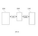
1210:集群1210: cluster
1220:管理伺服器1220: Manage server
1230:工作程序1230: Working procedures
1240:影像擷取裝置1240: image capture device
1310:步驟1310: step
1312:步驟1312:Step
1314:步驟1314:step
1320:步驟1320: step
1322:步驟1322:Step
1330:步驟1330: step
1332:步驟1332:step
1334:步驟1334:step
1336:步驟1336:step
1340:步驟1340: step
1342:步驟1342:step
1344:步驟1344:step
1910:基板1910: Substrates
1912:基板台1912: Substrate table
1920:電子束檢測設備1920: Electron beam inspection equipment
1922:電子源1922: Electron source
1924:初級電子束1924: Primary Electron Beam
1926:聚光器透鏡1926: Concentrator lens
1928:光束偏轉器1928: Beam deflector
1930:E×B偏轉器1930: E×B deflector
1932:物鏡1932: Objective lens
1934:二次電子偵測器1934:Secondary Electron Detector
1936:類比/數位轉換器1936: Analog/Digital Converter
1950:影像處理系統1950: Image processing system
1954:顯示裝置1954: Display device
1956:記憶體1956: Memory
1958:處理單元1958: Processing unit
2110:平均影像2110: average image
2120:原始影像2120: Original image
2210:原始影像2210: Original image
2220:良好平均影像2220: good average image
2230:切線2230: Tangent
2240:原始影像2240: Original image
2250:不良平均影像2250: bad average image
2310:步驟2310: step
2320:步驟2320: step
2330:步驟2330: step
2340:步驟2340:step
2350:步驟2350: step
2360:步驟2360: step
2370:步驟2370:step
2380:步驟2380:step
2410:步驟2410: step
2420:步驟2420: step
2430:模型2430: model
2432:步驟2432:step
2434:步驟2434:step
2440:步驟2440: step
2450:步驟2450: step
2460:步驟2460: step
2470:步驟2470:step
2480:步驟2480: step
2490:步驟2490:step
AD:調整構件AD: adjust the component
B:輻射光束B: radiation beam
BS:匯流排BS: bus bar
C:目標部分C: target part
CC:游標控制件CC: Cursor Control
CI:通信介面CI: Communication Interface
CO:聚光器CO: concentrator
CS:電腦系統CS: computer system
DS:顯示器DS: display
Ex:光束擴展器Ex: beam expander
HC:主電腦HC: main computer
ID:輸入裝置ID: input device
IF:虛擬源點IF: virtual origin
IL:照明系統IL: lighting system
IN:積光器IN: light integrator
INT:網際網路INT: Internet
LAN:區域網路LAN: local area network
LPA:微影投影設備LPA: Lithography projection equipment
M1:圖案化裝置對準標記M1: patterning device alignment mark
M2:圖案化裝置對準標記M2: Patterning Device Alignment Mark
MA:圖案化裝置MA: patterning device
MM:主記憶體MM: main memory
MT:第一物件台MT: first object table
NDL:網路鏈路NDL: Network Link
O:點虛線O: dotted line
P1:基板對準標記P1: Substrate alignment mark
P2:基板對準標記P2: Substrate alignment mark
PB:光束PB: Beam
PL:透鏡PL: lens
PM:第一定位器PM: First Locator
PRO:處理器PRO: Processor
PS:投影系統PS: projection system
PS1:位置感測器PS1: position sensor
PS2:位置感測器PS2: position sensor
PW:第二定位器PW: second locator
ROM:唯讀記憶體ROM: read only memory
SD:儲存裝置SD: storage device
SO:輻射源SO: radiation source
W:基板W: Substrate
WT:第二物件台WT: second object table
X:方向X: direction
Y:方向Y: Direction
併入在本說明書中且構成本說明書之一部分的隨附圖式展示本文中所揭示之主題的某些態樣,且與描述一起,有助於解釋與所揭示實施例相關聯之一些原理。在圖式中,圖1說明根據一實施例的微影投影設備之各種子系統的方塊圖。The accompanying drawings, which are incorporated in and constitute a part of this specification, illustrate certain aspects of the subject matter disclosed herein and, together with the description, help explain some of the principles associated with the disclosed embodiments. In the drawings, FIG. 1 illustrates a block diagram of various subsystems of a lithography projection apparatus according to one embodiment.
圖2說明根據一實施例的用於模擬微影投影設備中之微影的例示性流程圖。2 illustrates an exemplary flow diagram for simulating lithography in a lithography projection apparatus, according to an embodiment.
圖3說明根據一實施例的自印刷圖案之影像獲得的例示性經量測輪廓。Figure 3 illustrates an exemplary measured profile obtained from an image of a printed pattern according to one embodiment.
圖4說明根據一實施例的藉由對多個影像進行平均來產生經量測輪廓之例示性方法。4 illustrates an exemplary method of generating a measured profile by averaging multiple images, according to one embodiment.
圖5說明根據一實施例的對準經量測輪廓與經模擬輪廓之例示性方法。5 illustrates an exemplary method of aligning measured and simulated profiles according to an embodiment.
圖6說明根據一實施例的判定經量測輪廓與經模擬輪廓之間的偏移之例示性方法。6 illustrates an exemplary method of determining an offset between a measured profile and a simulated profile, according to an embodiment.
圖7說明根據一實施例的將經模擬輪廓與經量測輪廓匹配之例示性改良。7 illustrates an exemplary refinement of matching simulated profiles to measured profiles, according to an embodiment.
圖8說明根據一實施例的基於改良初步模型而對準之例示性改良。Figure 8 illustrates an exemplary refinement of alignment based on a refined preliminary model, according to one embodiment.
圖9說明根據一實施例的校準程序模型之例示性方法。Figure 9 illustrates an exemplary method of calibrating a program model according to one embodiment.
圖10說明根據一實施例的校準OPC模型之例示性方法。Figure 10 illustrates an exemplary method of calibrating an OPC model, according to one embodiment.
圖11說明根據一實施例的獲取目標之多個影像及校準程序模型的例示性方法。11 illustrates an exemplary method of acquiring multiple images of a target and calibrating a procedural model, according to one embodiment.
圖12為根據一實施例的實例電腦系統之方塊圖。Figure 12 is a block diagram of an example computer system according to one embodiment.
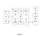
圖13為根據一實施例的實例度量系統之方塊圖。Figure 13 is a block diagram of an example metrology system, according to one embodiment.
圖14為根據一實施例的改良之度量衡程序的實例實施方式之程序流程圖。14 is a program flow diagram of an example implementation of an improved weights and measures program according to an embodiment.
圖15為根據一實施例的微影投影設備之示意圖。FIG. 15 is a schematic diagram of a lithography projection apparatus according to an embodiment.
圖16為根據一實施例的另一微影投影設備之示意圖。FIG. 16 is a schematic diagram of another lithography projection apparatus according to an embodiment.
圖17為根據一實施例的微影投影設備之詳細視圖。Figure 17 is a detailed view of a lithography projection apparatus according to an embodiment.
圖18為根據一實施例的微影投影設備之源收集器模組的詳細視圖。Figure 18 is a detailed view of a source collector module of a lithographic projection apparatus according to one embodiment.
圖19示意性地描繪根據一實施例的電子束檢測設備之實施例。Figure 19 schematically depicts an embodiment of an electron beam inspection apparatus according to an embodiment.
圖20示意性地說明根據一實施例的檢測設備之另一實施例。Fig. 20 schematically illustrates another embodiment of a detection apparatus according to an embodiment.
圖21為說明根據一實施例的印刷圖案的原始影像及平均影像之圖式。21 is a diagram illustrating an original image and an average image of a printed pattern according to one embodiment.
圖22為說明根據一實施例的印刷圖案的「良好」及「不良」平均影像之圖式。22 is a graph illustrating "good" and "bad" average images of printed patterns according to one embodiment.
圖23為說明根據一實施例的影像品質分級模型的例示性實施方式之程序流程圖。23 is a process flow diagram illustrating an exemplary implementation of an image quality classification model according to an embodiment.
圖24為說明根據一實施例的迭代地改良平均影像的例示性影像品質分級模型之程序流程圖。24 is a process flow diagram illustrating an exemplary image quality classification model for iteratively improving an average image according to one embodiment.
儘管在本文中可具體地參考IC之製造,但應明確理解,本文中之描述具有許多其他可能應用。舉例而言,其可用於整合式光學系統之製造、磁疇記憶體之導引及偵測圖案、液晶顯示面板、薄膜磁頭等。熟習此項技術者將瞭解,在此等替代性應用之上下文中,本文中對術語「倍縮光罩」、「晶圓」或「晶粒」之任何使用應視為可分別與更一般的術語「光罩」、「基板」及「目標部分」互換。Although specific reference may be made herein to the fabrication of ICs, it is expressly understood that the descriptions herein have many other possible applications. For example, it can be used in the manufacture of integrated optical systems, guiding and detecting patterns of magnetic domain memory, liquid crystal display panels, thin film magnetic heads, etc. Those skilled in the art will appreciate that any use of the terms "reticle," "wafer," or "die" herein in the context of such alternative applications should be considered separately and more generally The terms "reticle", "substrate" and "target portion" are used interchangeably.
在本發明之文件中,術語「輻射」及「光束」用於涵蓋所有類型之電磁輻射,包括紫外輻射(例如具有為365nm、248nm、193nm、157nm或126nm之波長)及極紫外線輻射(EUV,例如具有在約5nm至100nm之範圍內之波長)。In this document, the terms "radiation" and "beam" are used to cover all types of electromagnetic radiation, including ultraviolet radiation (for example having a wavelength of 365nm, 248nm, 193nm, 157nm or 126nm) and extreme ultraviolet radiation (EUV, For example with a wavelength in the range of about 5nm to 100nm).
圖案化裝置可包含或可形成一或多個設計佈局。可利用電腦輔助設計(CAD)程式來產生設計佈局,此程序常常被稱作電子設計自動化(EDA)。大多數CAD程式遵循預定設計規則集合,以便產生功能設計佈局/圖案化裝置。藉由處理及設計限制來設定此等規則。舉例而言,設計規則界定裝置(諸如閘極、電容器等)或互連線之間的空間容許度,以便確保裝置或線不會以非所要之方式彼此相互作用。設計規則限制中之一或多者可被稱作「臨界尺寸」(CD)。可將裝置之臨界尺寸界定為線或孔之最小寬度或兩條線或兩個孔之間的最小空間。因此,CD判定經設計裝置之總大小及密度。當然,裝置製造之目標中之一者為(經由圖案化裝置)在基板上如實地再生原始設計意圖。A patterning device may contain or may form one or more design layouts. Design layouts may be generated using a computer-aided design (CAD) program, often referred to as electronic design automation (EDA). Most CAD programs follow a predetermined set of design rules in order to generate a functional design layout/patterned device. These rules are set by processing and design constraints. For example, design rules define the space tolerances between devices (such as gates, capacitors, etc.) or interconnect lines in order to ensure that the devices or lines do not interact with each other in unwanted ways. One or more of the design rule constraints may be referred to as a "critical dimension" (CD). The critical dimension of a device can be defined as the minimum width of a line or hole or the minimum space between two lines or two holes. Therefore, CD determines the overall size and density of the designed device. Of course, one of the goals of device fabrication is to faithfully reproduce the original design intent on the substrate (via patterning the device).
如本文中所使用之術語「光罩」或「圖案化裝置」可被廣泛地解釋為指代可用於向入射輻射光束賦予經圖案化橫截面之通用圖案化裝置,經圖案化橫截面對應於待在基板之目標部分中產生之圖案;術語「光閥」亦可用於此上下文中。除經典光罩(透射式或反射式;二元、相移、混合式等)以外,其他此等圖案化裝置之實例包括可程式化鏡面陣列及可程式化LCD陣列。The term "reticle" or "patterning device" as used herein may be broadly interpreted to refer to a general patterning device that can be used to impart a patterned cross-section to an incident radiation beam, the patterned cross-section corresponding to A pattern to be created in a target portion of a substrate; the term "light valve" may also be used in this context. Besides classical reticles (transmissive or reflective; binary, phase shift, hybrid, etc.), other examples of such patterning devices include programmable mirror arrays and programmable LCD arrays.
可程式化鏡面陣列之實例可為具有黏彈性控制層及反射表面之矩陣可定址表面。此設備所隱含之基本原理為(例如):反射表面之經定址區域使入射輻射反射為繞射輻射,而未經定址區域使入射輻射反射為非繞射輻射。在使用適當濾波器之情況下,可自反射光束濾出該非繞射輻射,從而僅留下繞射輻射;以此方式,光束根據矩陣可定址表面之定址圖案而變得圖案化。可使用合適電子構件來執行所需矩陣定址。An example of a programmable mirror array may be a matrix addressable surface with a viscoelastic control layer and a reflective surface. The rationale underlying this device is, for example, that addressed areas of the reflective surface reflect incident radiation as diffracted radiation, while unaddressed areas reflect incident radiation asnon-diffraction radiation. With the use of appropriate filters, this non-diffracted radiation can be filtered out from the reflected beam, leaving only the diffracted radiation; in this way, the beam becomes patterned according to the addressing pattern of the matrix addressable surface. The required matrix addressing can be performed using suitable electronic components.
可程式化LCD陣列之實例在以引用之方式併入本文中之美國專利第5,229,872號中給出。An example of a programmable LCD array is given in US Patent No. 5,229,872, which is incorporated herein by reference.
圖1說明根據一實施例的微影投影設備10A之各種子系統的方塊圖。主要組件為:輻射源12A,其可為深紫外線準分子雷射源或包括極紫外線(EUV)源之其他類型源(如上文所論述,微影投影設備自身不必具有輻射源);照明光學件,其例如界定部分相干性(經表示為均方偏差)且可包括塑形來自源12A之輻射的光學件14A、16Aa及16Ab;圖案化裝置18A;及透射光學件16Ac,其將圖案化裝置圖案之影像投影至基板平面22A上。在投影光學件之光瞳平面處的可調整濾波器或孔徑20A可限定照射於基板平面22A上之光束角度之範圍,其中最大可能角度界定投影光學件之數值孔徑NA=n sin(Θmax),其中n為基板與投影光學件之最後元件之間的媒體之折射率,且Θmax為自投影光學件射出的仍可照射於基板平面22A上之光束的最大角度。FIG. 1 illustrates a block diagram of various subsystems of a
在微影投影設備中,源將照明(亦即,輻射)提供至圖案化裝置,且投影光學件經由圖案化裝置將照明導向至基板上且塑形該照明。投影光學件可包括組件14A、16Aa、16Ab及16Ac中之至少一些。空中影像(AI)為在基板位階處之輻射強度分佈。抗蝕劑模型可用於自空中影像計算抗蝕劑影像,此情形之實例可見於全部揭示內容特此以引用方式併入之美國專利申請公開案第US 2009-0157630號。抗蝕劑模型僅與抗蝕劑層之性質(例如在曝光、曝光後烘烤(PEB)及顯影期間發生的化學程序之效應)有關。微影投影設備之光學性質(例如照明、圖案化裝置及投影光學件之性質)指明空中影像且可界定於光學模型中。由於可改變用於微影投影設備中之圖案化裝置,因此需要將圖案化裝置之光學性質與至少包括源及投影光學件的微影投影設備之其餘部分之光學性質分離。用於將設計佈局變換至各種微影影像(例如空中影像、抗蝕劑影像等)、使用彼等技術及模型應用OPC且評估效能(例如依據程序窗)的技術及模型之細節描述於美國專利申請公開案US 2008-0301620、2007-0050749、2007-0031745、2008-0309897、2010-0162197及2010-0180251中,前述各案之揭示內容特此以全文引用之方式併入。In a lithographic projection apparatus, a source provides illumination (ie, radiation) to a patterning device, and projection optics direct and shape the illumination onto a substrate through the patterning device. Projection optics may include at least some of
理解微影程序之一個態樣為理解輻射與圖案化裝置之相互作用。可自在輻射到達圖案化裝置之前的輻射之電磁場及表徵該相互作用之函數判定在輻射通過圖案化裝置之後的輻射之電磁場。此函數可被稱作光罩透射函數(其可用於描述透射圖案化裝置及/或反射圖案化裝置之相互作用)。One aspect of understanding the lithography process is understanding the interaction of radiation with the patterning device. The electromagnetic field of the radiation after it has passed through the patterning device can be determined from the electromagnetic field of the radiation before it reaches the patterning device and the function characterizing the interaction. This function may be referred to as a reticle transmission function (which may be used to describe the interaction of a transmissive patterning device and/or a reflective patterning device).
光罩透射函數可具有各種不同形式。一種形式為二元的。二元光罩透射函數在圖案化裝置上之任何給定部位處具有兩個值(例如零及正常數)中之任一者。呈二元形式之光罩透射函數可被稱作二元光罩。另一種形式為連續的。即,圖案化裝置之透射率(或反射率)之模數為圖案化裝置上之部位的連續函數。透射率(或反射率)之相位亦可為圖案化裝置上之部位的連續函數。呈連續形式之光罩透射函數可被稱作連續色調光罩或連續透射光罩(CTM)。舉例而言,可將CTM表示為像素化影像,其中可向每一像素指派介於0與1之間的值(例如0.1、0.2、0.3等)來代替0或1之二元值。在一實施例中,CTM可為像素化灰階影像,其中每一像素具有若干值(例如在範圍[-255,255]內、在範圍[0,1]或[-1,1]或其他適當範圍內之正規化值)。The reticle transmission function can have various forms. One form is binary. A binary reticle transmission function has either of two values (eg, zero and a normal constant) at any given location on the patterning device. A reticle transmission function in binary form may be referred to as a binary reticle. Another form is continuous. That is, the modulus of the transmittance (or reflectance) of the patterned device is a continuous function of the site on the patterned device. The phase of the transmittance (or reflectance) can also be a continuous function of the site on the patterned device. A mask transmission function in continuous form may be referred to as a continuous tone mask or a continuous transmission mask (CTM). For example, a CTM can be represented as a pixelated image, where each pixel can be assigned a value between 0 and 1 (eg, 0.1, 0.2, 0.3, etc.) instead of a binary value of 0 or 1 . In one embodiment, the CTM can be a pixelated grayscale image, where each pixel hasA number of values (such as normalized values in the range [-255,255], in the range [0,1] or [-1,1], or other suitable ranges).
薄光罩近似(亦被稱為克希霍夫(Kirchhoff)邊界條件)廣泛地用於簡化對輻射與圖案化裝置之相互作用之判定。薄光罩近似假定圖案化裝置上之結構之厚度相較於波長極小,且光罩上之結構之寬度相較於波長極大。因此,薄光罩近似假定在圖案化裝置之後的電磁場為入射電磁場與光罩透射函數之乘積。然而,當微影程序使用具有愈來愈短之波長的輻射,且圖案化裝置上之結構變得愈來愈小時,對薄光罩近似之假定可分解。舉例而言,由於結構(例如頂面與側壁之間的邊緣)之有限厚度,輻射與結構之相互作用(「光罩3D效應」或「M3D」)可變得顯著。在光罩透射函數中涵蓋此散射可使得光罩透射函數能夠較佳地擷取輻射與圖案化裝置之相互作用。在薄光罩近似下之光罩透射函數可被稱作薄光罩透射函數。涵蓋M3D之光罩透射函數可被稱作M3D光罩透射函數。The thin reticle approximation (also known as the Kirchhoff boundary condition) is widely used to simplify the determination of the interaction of radiation with the patterning device. The thin reticle approximation assumes that the thickness of the structures on the patterned device is extremely small compared to the wavelength, and that the width of the structures on the reticle is extremely large compared to the wavelength. Thus, the thin reticle approximation assumes that the electromagnetic field after the patterning device is the product of the incident electromagnetic field and the reticle transmission function. However, as lithography processes use radiation with shorter and shorter wavelengths, and the structures on the patterned devices become smaller and smaller, the assumption of the thin reticle approximation breaks down. For example, due to the finite thickness of the structure (eg, the edge between the top surface and the sidewall), the interaction of radiation with the structure ("reticle 3D effect" or "M3D") can become significant. Including this scattering in the reticle transmission function enables the reticle transmission function to better capture the interaction of the radiation with the patterning device. A reticle transmission function under the thin reticle approximation may be referred to as a thin reticle transmission function. A mask transmission function encompassing M3D may be referred to as an M3D mask transmission function.
根據本發明之一實施例,可產生一或多個影像。影像包括可藉由每一像素之像素值或強度值表徵的各種類型之信號。視影像內像素之相對值而定,信號可被稱作例如弱信號或強信號,如一般熟習此項技術者可理解。術語「強」及「弱」為基於影像內之像素之強度值的相對術語,且強度之具體值可能並不限制本發明之範疇。在一實施例中,強信號及弱信號可基於所選擇之臨限值來識別。在一實施例中,臨限值可為固定的(例如影像內像素之最高強度與最低強度的中點)。在一實施例中,強信號可指具有大於或等於跨影像之平均信號值之值的信號,且弱信號可指具有小於平均信號值之值的信號。在一實施例中,相對強度值可基於百分比。舉例而言,弱信號可為具有低於影像內像素(例如對應於目標圖案之像素可被視為具有最高強度之像素)之最高強度的50%的強度之信號。此外,影像內之每一像素可被視為變數。根據本發明實施例,導數或偏導數可相對於影像內之每一像素予以判定,且每一像素之值可根據基於成本函數之評估及/或成本函數之基於梯度的計算來判定或修改。舉例而言,CTM影像可包括像素,其中每一像素為可採用任何實值之變數。According to an embodiment of the invention, one or more images may be generated. Images include various types of signals that can be characterized by a pixel value or intensity value for each pixel. Depending on the relative values of the pixels within the image, the signal may be referred to as, for example, a weak signal or a strong signal, as would be understood by those of ordinary skill in the art. The terms "strong" and "weak" are relative terms based on the intensity values of pixels within an image, and specific values of intensities may not limit the scope of the invention. In one embodiment, strong and weak signals may be identified based on a selected threshold. In one embodiment, the threshold may be fixed (eg, the midpoint between the highest and lowest intensity of a pixel in the image). In an embodiment, a strong signal may refer to a signal having a value greater than or equal to the average signal value across images, and a weak signal may refer to a signal having a value less than the average signal value. In one embodiment, relative intensity values may be based on percentages. For example, a weak signal may have a pixel with a lower thanA pixel can be considered to have a signal with an intensity of 50% of the highest intensity of the pixel with the highest intensity. Additionally, each pixel within an image can be considered a variable. According to embodiments of the present invention, derivatives or partial derivatives may be determined relative to each pixel within an image, and the value of each pixel may be determined or modified based on cost function based evaluation and/or gradient based calculation of cost function. For example, a CTM image can include pixels, where each pixel is a variable that can take any real value.
圖2說明根據一實施例的用於模擬微影投影設備中之微影的例示性流程圖。源模型31表示源之光學特性(包括輻射強度分佈及/或相位分佈)。投影光學件模型32表示投影光學件之光學特性(包括由投影光學件引起的輻射強度分佈及/或相位分佈之變化)。設計佈局模型35表示設計佈局之光學特性(包括由設計佈局33引起的輻射強度分佈及/或相位分佈之變化),該設計佈局為在圖案化裝置上或藉由圖案化裝置形成之特徵配置的表示。可自設計佈局模型35、投影光學件模型32及設計佈局模型35來模擬空中影像36。可使用抗蝕劑模型37自空中影像36模擬抗蝕劑影像38。微影之模擬可例如預測抗蝕劑影像中之輪廓及CD。2 illustrates an exemplary flow diagram for simulating lithography in a lithography projection apparatus, according to an embodiment. The
更具體而言,應注意,源模型31可表示源之光學特性,該等光學特性包括但不限於數值孔徑設定、照明均方偏差(σ)設定,以及任何特定照明形狀(例如離軸輻射源,諸如環圈、四極子、偶極子等)。投影光學件模型32可表示投影光學件之光學特性,該等光學特性包括像差、失真、一或多個折射率、一或多個實體大小、一或多個實體尺寸等。設計佈局模型35可表示實體圖案化裝置之一或多個物理性質,如(例如)以全文引用之方式併入之美國專利第7,587,704號中所描述。模擬之目標為準確地預測例如邊緣置放、空中影像強度斜率及/或CD,可接著將邊緣置放、空中影像強度斜率及/或CD與預期設計進行比較。預期設計通常被定義為可以諸如GDSII或OASIS或其他檔案格式之標準化數位檔案格式而提供之預OPC設計佈局。More specifically, it should be noted that the
根據此設計佈局,可識別被稱作「剪輯」之一或多個部分。在一實施例中,提取剪輯集合,其表示設計佈局中之複雜圖案(通常為約50個至1000個剪輯,但可使用任何數目個剪輯)。此等圖案或剪輯表示設計之較小部分(亦即,電路、單元或圖案),且更具體而言,該等剪輯通常表示需要特定注意及/或驗證的較小部分。換言之,剪輯可為設計佈局之部分,或可為類似的或具有設計佈局之部分的類似行為,其中一或多個臨界特徵藉由體驗(包括由客戶提供之剪輯)、試誤法或執行全晶片模擬來予以識別。剪輯可含有一或多個測試圖案或量規圖案。From this design layout, one or more parts called "clips" can be identified. In one embodiment, a collection of clips is extracted that represents complex patterns in a design layout (typically about 50 to 1000 clips, although any number of clips may be used). These patterns or clips represent smaller portions of the design (ie, circuits, cells, or patterns), and more specifically, the clips typically represent smaller portions that require specific attention and/or verification. In other words, a clip may be part of a design layout, or may be a similar act or a similar behavior with a part of a design layout, where one or more critical features are determined by experience (including clips provided by customers), trial and error, or by implementing a full Wafer simulation to be identified. A clip can contain one or more test patterns or gauge patterns.
可由客戶基於設計佈局中需要特定影像最佳化之已知臨界特徵區域而先驗地提供初始較大剪輯集合。可替代地,在另一實施例中,可藉由使用識別該一或多個臨界特徵區域之某種自動(諸如機器視覺)或手動演算法自整個設計佈局提取初始較大剪輯集合。An initial large set of clips can be provided a priori by the customer based on known critical feature areas in the design layout that require specific image optimization. Alternatively, in another embodiment, an initial larger set of clips may be extracted from the entire design layout by using some automated (such as machine vision) or manual algorithm that identifies the one or more critical feature regions.
在微影投影設備中,作為實例,可將成本函數表示為
其中(z1,z2,…,zN)為N個設計變數或其值。fp(z1,z2,…,zN)可為設計變數(z1,z2,…,zN)之函數,諸如對於(z1,z2,…,zN)之設計變數的值集合的特性之實際值與預期值之間的差。wp為與fp(z1,z2,…,zN)相關聯之權重常數。舉例而言,特性可為在邊緣上之給定點處量測的圖案之邊緣之位置。不同fp(z1,z2,…,zN)可具有不同權重wp。舉例而言,若特定邊緣具有所准許位置之窄範圍,則用於表示邊緣之實際位置與預期位置之間的差之fp(z1,z2,…,zN)之權重wp可被給出較高值。fp(z1,z2,…,zN)亦可為層間特性之函數,層間特性又為設計變數(z1,z2,…,zN)之函數。當然,CF(z1,z2,…,zN)不限於方程式1中之形式。CF(z1,z2,…,zN)可呈任何其他合適形式。Where (z1 ,z2 ,…,zN ) are N design variables or their values.fp (z1 ,z2 ,…,zN ) can be a function of design variables (z1 ,z2 ,…,zN ), such as for (z1 ,z2 ,…,zN ) The difference between the actual value and the expected value of a property for a set of values for .wp is the weight constant associated withfp (z1 ,z2 ,…,zN ). For example, the characteristic may be the position of the edge of the pattern measured at a given point on the edge. Differentfp (z1 ,z2 , . . . ,zN ) may have different weightswp . For example, if a particular edge has a narrow range of permitted locations, theweight wpforfp(z1,z2,...,zN)representingthedifference between the edge's actual location and expectedlocation can be is given a higher value.fp (z1 ,z2 ,…,zN ) can also be a function of interlayer properties, which in turn is a function of design variables (z1 ,z2 ,…,zN ). Of course,CF (z1 ,z2 ,…,zN ) is not limited to the form in
成本函數可表示微影投影設備、微影程序或基板之任一個或多個合適特性,例如,焦點、CD、影像移位、影像失真、影像旋轉、隨機變化、產出率、局域CD變化、程序窗、層間特性或其組合。在一個實施例中,設計變數(z1,z2,…,zN)包含選自劑量、圖案化裝置之全域偏置及/或照明形狀中之一或多者。由於抗蝕劑影像常常規定基板上之圖案,因此成本函數可包括表示抗蝕劑影像之一或多個特性的函數。舉例而言,fp(z1,z2,…,zN)可僅為抗蝕劑影像中之一點與彼點之預期位置之間的距離(亦即,邊緣置放誤差EPEp(z1,z2,…,zN))。設計變數可包括任何可調整參數,諸如源、圖案化裝置、投影光學件、劑量、焦點等之可調整參數。The cost function may represent any one or more suitable properties of the lithography projection device, lithography process, or substrate, for example, focus, CD, image shift, image distortion, image rotation, random variation, yield, local CD variation , program window, interlayer properties, or a combination thereof. In one embodiment, the design variables (z1 ,z2 , . . . ,zN ) include one or more selected from dose, global bias of the patterning device, and/or illumination shape. Since a resist image often defines a pattern on a substrate, the cost function may include a function representing one or more properties of the resist image. For example,fp (z1 ,z2 ,...,zN ) may simply be the distance between a point in the resist image and the expected position of that point (ie, the edge placement errorEPEp (z1 ,z2 ,…,zN )). Design variables may include any adjustable parameters, such as those of source, patterning device, projection optics, dose, focus, and the like.
微影設備可包括可用於調整波前及強度分佈之形狀及/或輻射光束之相移的被統稱為「波前操控器」之組件。在一實施例中,微影設備可調整沿著微影投影設備之光程之任何部位處(諸如在圖案化裝置之前、在光瞳平面附近、在影像平面附近及/或在焦點平面附近)的波前及強度分佈。波前操控器可用於校正或補償由例如源、圖案化裝置、微影投影設備中之溫度變化、微影投影設備之組件的熱膨脹等所引起的波前及強度分佈及/或相移的某些失真。調整波前及強度分佈及/或相移可改變由成本函數表示之特性的值。可自模型模擬此等變化或實際上量測此等變化。設計變數可包括波前操控器之參數。A lithographic apparatus may include components collectively referred to as "wavefront manipulators" that may be used to adjust the shape of the wavefront and intensity distribution and/or the phase shift of a radiation beam. In one embodiment, the lithographic apparatus can be adjusted anywhere along the optical path of the lithographic projection apparatus (such as before the patterning device, near the pupil plane, near the image plane, and/or near the focal plane) wavefront and intensity distribution. The wavefront manipulator can be used to correct or compensate for certain changes in the wavefront and intensity distribution and/or phase shift caused by, for example, source, patterning device, temperature changes in the lithographic projection apparatus, thermal expansion of components of the lithographic projection apparatus, etc. some distortion. Adjusting the wavefront and intensity distribution and/or phase shift can change the value of the property represented by the cost function. Such changes can be simulated from a model or actually measured. Design variables may include parameters of the wavefront manipulator.
設計變數可具有約束,可將該等約束表示為(z1,z2,…,zN)
如本文中所使用,術語「圖案化程序」通常意謂作為微影程序之部分的藉由施加光之所指定圖案來產生經蝕刻基板的程序。然而,「圖案化程序」亦可包括電漿蝕刻,此係由於本文中所描述的許多特徵可提供使用電漿處理形成印刷圖案之益處。As used herein, the term "patterning process" generally means the process of creating an etched substrate by applying a specified pattern of light as part of a lithography process. However, a "patterning process" may also include plasma etching, as many of the features described herein provide the benefit of using plasma processing to form printed patterns.
如本文中所使用,術語「目標圖案」意謂將在基板上蝕刻之理想化圖案。As used herein, the term "target pattern" means an idealized pattern to be etched on a substrate.
如本文中所使用,術語「印刷圖案」意謂基板上之基於目標圖案蝕刻的實體圖案。印刷圖案可包括例如凹槽、通道、凹陷、邊緣或由微影程序產生之其他兩維及三維特徵。As used herein, the term "printed pattern" means a physical pattern etched based on a target pattern on a substrate. Printed patterns may include, for example, grooves, channels, depressions, edges, or other two- and three-dimensional features produced by lithographic processes.
如本文中所使用,術語「程序模型」意謂包括模擬圖案化程序之一或多個模型的模型。舉例而言,程序模型可包括光學模型(例如模型化用於在微影程序中遞送光的透鏡系統/投影系統且可包括模型化去向光致抗蝕劑(photoresist)上的光之最終光學影像)、抗蝕劑模型(例如模型化抗蝕劑之實體效應,諸如歸因於光之化學效應),及OPC模型(例如可用於製造目標圖案且可包括子解析度抗蝕劑特徵(SRAF)等)。As used herein, the term "process model" means a model comprising one or more models of a simulated patterning process. For example, process models may include optical models such as modeling the lens system/projection system used to deliver light in a lithography process and may include modeling the final optical image of light going to a photoresist ), resist models (e.g. model physical effects of resist, such as chemical effects due to light), and OPC models (e.g. can be used to fabricate target patterns and may include sub-resolution resist feature (SRAF) Wait).
如本文中所使用,術語「校準」意謂修改(例如改良或調節)及/或驗證某物,諸如程序模型。As used herein, the term "calibration" means modification (such as improvement or adjustmentsection) and/or verify something, such as a program model.
此外,本發明描述用於改良圖案化程序之程序模型的方法。在程序模型校準期間改良度量可包括獲得基於目標圖案的印刷圖案(例如印刷晶圓或其部分)之準確影像。根據影像,可提取對應於印刷圖案上之特徵的輪廓。接著可將輪廓(亦稱作經量測輪廓)與藉由程序模型產生之經模擬輪廓對準,以允許程序模型之校準。可藉由調整程序模型中之參數來改良程序模型,使得經模擬輪廓能夠更準確地匹配經量測輪廓。Furthermore, the present invention describes methods for improving the process model of the patterning process. Improving metrics during process model calibration may include obtaining an accurate image of a printed pattern (eg, a printed wafer or portion thereof) based on a target pattern. From the images, contours corresponding to features on the printed pattern can be extracted. The profile (also referred to as the measured profile) can then be aligned with the simulated profile generated by the procedural model to allow calibration of the procedural model. The program model can be improved by adjusting parameters in the program model so that the simulated profile matches the measured profile more accurately.
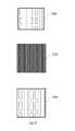
圖3說明根據一實施例的自印刷圖案之影像獲得的例示性經量測輪廓330。FIG. 3 illustrates an exemplary measured
微影程序可基於例如目標圖案310(在圖3之上部圖(top panel)中所展示)產生印刷圖案(例如用於積體電路或電腦晶片之電路圖案)。歸因於圖案化程序之限制,印刷圖案將大體上僅僅為目標圖案310之近似。The lithography process may generate a printed pattern (eg, a circuit pattern for an integrated circuit or a computer chip) based on, for example, target pattern 310 (shown in the top panel of FIG. 3 ). Due to the limitations of the patterning procedure, the printed pattern will generally only be an approximation of the
印刷圖案可藉由影像擷取裝置成像以產生經量測影像320(在圖3之中間圖中所展示),其含有對應於目標圖案310中之理想化形狀的輪廓。在一個實施例中,方法可包括:自影像擷取裝置(例如掃描電子顯微鏡(亦被稱作電子束檢測系統))獲得經量測輪廓330。參看圖19及圖20更詳細地描述電子束檢測系統之例示性實施例。電子束檢測系統可類似於掃描電子顯微鏡,但具有大視場(LFOV)及高產出率以用於獲得經量測影像320。電子束檢測系統之一個非限制性實例可為HMI eP5,具體而言經組態以具有LFOV。在一些實施例中,LFOV可在一側量測例如大致1至1000微米、100至500微米、1至50微米、6至12微米等。影像擷取裝置可經組態以偵測印刷圖案中之熱點及/或弱點以及記憶體陣列之閘極及主動區域,諸如靜態隨機存取記憶體(SRAM)。如圖3中所說明,經量測影像320類似於印刷圖案,但經量測影像320中之矩形特徵展示圓化且稍微失真的線。The printed pattern can be imaged by an image capture device to produce a measured image 320 (shown in the middle panel of FIG. 3 ) containing an outline corresponding to the idealized shape in the
一些實施例可包括基於經量測影像320中之像素之強度的變化來識別經量測輪廓330(在圖3之下部圖中所展示)。影像分析技術可用於識別經量測影像320中之經量測輪廓330。強度、梯度及類似者之變化可例如與邊緣判定一起使用來識別印刷圖案中之特徵之高度(或深度)的變化。舉例而言,當將經量測影像表示為灰度影像時,當變化超過灰度臨限值(亦即,高於或低於定義值之強度)時,此可識別邊緣(亦即,經量測輪廓330)。Some embodiments may include identifying measured contours 330 (shown in the lower panel of FIG. 3 ) based on changes in the intensity of pixels in the measured
圖4說明根據一實施例的藉由對多個影像進行平均來產生經量測輪廓330之例示性方法。FIG. 4 illustrates an exemplary method of generating a measured
如上文所描述,可自單個經量測影像320提取經量測輪廓330。然而,在其他實施例中,印刷圖案之多個影像可組合成組合之影像420。組合影像減弱可存在於任何單個影像中之雜訊或其他形式之誤差的效應。在一個實施例中,可藉由對多個經量測影像410進行平均來產生組合之影像420。在其他實施例中,可在組合或平均之前對準多個經量測影像410。影像對準可基於例如多個經量測影像410之影像配准(諸如使用配准標記)、判定多個經量測影像410之間的最佳匹配的影像分析程式、基於多個經量測影像410來計算相關係數等。As described above, the measured
一旦自影像擷取裝置擷取之多個經量測影像410經對準,即可判定共同區域。如本文中所使用,術語「共同區域」意謂指代印刷圖案之相同實體區域的多個經量測影像410中之像素的集合。隨後,可基於共同區域來產生組合之經量測影像320。此可使得一些影像(其可具有較大或較小視場)使邊緣像素被移除,從而使得平均工序為均一的(亦即,相同數目個像素在每一像素處被平均)。Once the plurality of measured
來自重複電子束曝光之抗蝕劑收縮可在獲取多個影像時發生。可例如藉由其中多個經量測影像410自來自由目標圖案製成之至少兩個不同晶粒之印刷圖案獲得的實施例來減小抗蝕劑收縮。如本文中所使用,術語「晶粒」或「多個晶粒」意謂其上製造或將製造給定功能電路的半導電材料之區塊。在此等實施例中,晶粒具有類似印刷圖案,且因此可用於產生實質上同等之影像,同時減少印刷圖案至電子束之實體曝光。在其他實施例中,可藉由掃描不同晶粒來獲取產生組合之影像420的多個經量測影像410中之每一者。以此方式,用於產生組合之影像420的每一影像係基於單個印刷圖案。以此方式,在一些實施例中,可藉由運用以低於獲得足以解析臨界尺寸之掃描所需的劑量操作的掃描電子顯微鏡獲得經量測影像320來減小抗蝕劑收縮。Resist shrinkage from repeated e-beam exposures can occur when multiple images are acquired. Resist shrinkage can be reduced, for example, by embodiments in which the plurality of measured
在一些實施例中,獲得經量測影像320可藉由以若干角度在印刷圖案上掃描電子束來執行。角度可包括大致+45度及-45度。如本文中所使用,術語「大致」(例如關於掃描角度)意謂精確角度或非常接近於精確角度(例如在幾度或十分之一度內)之角度。在另一實施例中,可以大致+45度掃描經量測影像320之一半,且可以大致-45度掃描經量測影像320之另一半。In some embodiments, obtaining the measured
圖5說明根據一實施例的對準經量測輪廓330與經模擬輪廓510之例示性方法。FIG. 5 illustrates an exemplary method of aligning the measured
模擬印刷圖案的程序模型可包括抗蝕劑模型、光學模型、光學近接校正模型等之任何組合。因此,經模擬輪廓510可由程序模型之模擬產生。如本文中所使用,「經模擬輪廓510」意謂藉由一或多個計算模型產生且表示微影程序之預測結果(最終階段抑或中間階段)的輪廓。Program models for simulating printed patterns can include resist models, optical models,Any combination of optical proximity correction models, etc. Thus, the
為了校準程序模型,可將經量測輪廓330與經模擬輪廓510進行比較。作為校準程序之部分,經量測輪廓330可與經模擬輪廓510對準。在圖5之實例中,可將經量測輪廓330(如在此具體說明中藉由經量測影像320之圖形表示所表示)與經模擬輪廓510進行比較。在圖5之上部圖中,經量測輪廓330未與經模擬輪廓510適當地對準。如圖5之下部圖中所展示,經量測輪廓330可在經模擬輪廓510上平移及/或旋轉,直至經量測輪廓330大致位於正確位置中為止。此可提供可在如下文所描述後進一步改良之粗略對準。To calibrate the program model, the measured
圖6說明根據一實施例的判定經量測輪廓330與經模擬輪廓510之間的偏移610之例示性方法。FIG. 6 illustrates an exemplary method of determining an offset 610 between the measured
舉例而言,可在上文參看圖5所描述的粗略對準之後實施其他對準方法。此等實施方式可包括:藉由判定經量測輪廓330與經模擬輪廓510之間的偏移610來對準經量測輪廓330與經模擬輪廓510。如本文中所使用,「偏移610」意謂經量測輪廓330上之點與經模擬輪廓510上之另一點之間的距離。本發明提供用於判定偏移610之各種方法。舉例而言,可進一步基於實質上界定經量測輪廓330之一部分的量測座標620來判定偏移610。如本文中所使用,術語「量測座標」意謂界定經量測輪廓之一些或全部座標。可藉由成像裝置,藉由對由成像裝置拍攝之影像的分析等來產生量測座標。舉例而言,量測座標可為已經判定為對應於輪廓之邊緣的像素位置。因此,邊緣偵測程式可基於經量測影像320之影像處理來產生量測座標620。在圖6中藉由經量測輪廓330上之圓說明量測座標620之實例。For example, other alignment methods may be implemented after the coarse alignment described above with reference to FIG. 5 . Such embodiments may include aligning the measured
在一個實施例中,可進一步基於量測座標620與經模擬輪廓510之間的距離來判定偏移610。在一些具體實施例中,該等距離可位於在量測座標620處垂直於經量測輪廓330之方向上。在其他實施例中,可藉由例如對一些或全部偏移之距離的平方進行求和或對一些或全部偏移進行求和來判定對準之程度。此可例如經由垂直的偏移向量之x分量及/或y分量來執行。In one embodiment, the offset 610 may be further determined based on the distance between the measured coordinates 620 and the
在一些實施例中,對準可進一步包括減小基於距離計算之成本函數。上文描述成本函數之實例(例如方程式1之描述)。可藉由例如微調至經量測輪廓330之位置來減小成本函數。當成本函數在最小值(或另外令入滿意的值)處時,經量測輪廓330與經模擬輪廓510之對準可用於其他程序或用作程序模型校準之量測。In some embodiments, aligning may further include reducing a cost function calculated based on distance. Examples of cost functions (such as the description of Equation 1) are described above. The cost function can be reduced by, for example, fine-tuning to the position of the measured
為了提供額外點以用於本文中所描述之對準方法,某些實施例可包括:產生在經量測輪廓330上的任何數目個額外點(例如邊緣置放(EP)座標)。如本文中所使用,EP座標630(在本文中亦被稱作EP量規)為界定經量測輪廓330之額外點。在圖6中藉由位於經量測輪廓330上的實心正方形說明EP座標630之一個實例。在一些實施例中,可藉由在兩個或更多個量測座標620之間內插來產生EP座標630。在其他實施例中,可藉由自兩個或更多個量測座標620外推來產生EP座標630。因此,可替代地或除了量測座標620之外,可進一步基於EP座標630來判定偏移610。To provide additional points for use in the alignment methods described herein, some embodiments may include generating any number of additional points (eg, edge placement (EP) coordinates) on the measured
在一些實施例中,可自圖形資料庫系統(GDS)多邊形(亦即,藉由程序模型產生且對應於輪廓形狀的多邊形)獲得經模擬輪廓510。在其他實施例中,GDS多邊形可呈自GDS串流格式(GDSII)及開放式圖片系統互換標準(OASIS)中選擇的一或多個格式。接著,作為校準程序之部分,可將包含經量測模擬輪廓510之邊緣置放座標630及/或量測座標620轉換為GDS座標。此轉換可允許經模擬輪廓510與經量測輪廓330之間的更直接比較。In some embodiments, the
圖7說明根據一實施例的將經模擬輪廓510與經量測輪廓330匹配之例示性改良。FIG. 7 illustrates an exemplary refinement of matching the
本文中所描述的實施例可促進校準程序模型以提供經模擬輪廓510(藉由程序模型產生)與經量測輪廓330之間的更準確匹配。在一些實施例中,校準程序模型可包括減小經模擬輪廓510與經量測輪廓330之間的基於經判定偏移610計算的差。Embodiments described herein may facilitate calibrating the procedural model to provide a more accurate match between the simulated profile 510 (generated by the procedural model) and the measured
如本文中所使用,「差」意謂兩個或更多個輪廓之間的偏差度之經量化量測。差之一個非限制性實例為前述成本函數。差之另一實例亦可為兩個輪廓上之點之間的偏移或距離,但不在成本函數中使用此等點。As used herein, "difference" means a quantified measure of the degree of deviation between two or more profiles. One non-limiting example of a difference is the aforementioned cost function. Another example of a difference could also be the offset or distance between points on the two contours, but these points are not used in the cost function.
在一些實施例中,方法可包括:修改程序模型之特徵以減小該差。在一些實施例中,該修改可引起經模擬輪廓510之形狀的變化。可經修改的抗蝕劑模型之特徵的實例可包括擴散率、擴散範圍、去保護比率及酸/鹼濃度。以此方式執行的修改可被視為程序模型之「微調」以改良其預測經量測輪廓330的能力。在一些實施例中,此可導致改良之光學模型、抗蝕劑模型、OPC模型等。In some embodiments, the method may include modifying characteristics of the program model to reduce the difference. In some embodiments, this modification may cause a change in the shape of the
圖8說明根據一實施例的基於改良初步模型810而對準之例示性改良。Figure 8 illustrates an exemplary refinement of alignment based on a refined
改良程序模型(包括OPC模型)可以初步模型810而非例如完整程序模型(full process model)開始。舉例而言,一些實施例可包括:基於OPC模型之模擬來獲得經模擬輪廓510,其中OPC模型可為初步模型810。初步模型810可包括減小數目之模型組件,例如包括光學模型且不包括抗蝕劑模型。Improved process models (including OPC models) may start with a
在其他實施例中,方法可包括:獲得具有改良之初步模型820(例如包括光學模型及抗蝕劑模型)的初始模擬輪廓510。具體而言,一些實施例可包括:修改抗蝕劑模型之特徵以減小初始模擬輪廓510與經量測輪廓330之間的差。如上文關於抗蝕劑模型所描述,可經修改之特徵的實例可包括擴散率、擴散範圍、去保護比率及酸/鹼濃度。以此方式,初步模型810可經使用並如本文所描述一般進行改良。在其他實施例中,對初步模型810之修改可產生改良之初步模型820,其又產生經模擬輪廓510。此等迭代方法可提供逐漸改良之模擬輪廓510以用於本文中所描述的對準工序。In other embodiments, the method may include obtaining an initial
在本發明之一些實施例中,減少處理時間及計算額外負擔已實現。舉例而言,藉由利用包括影像平均(諸如參看圖4所描述)及準確影像對準(諸如參看圖3所描述)的特徵,用於影像獲取之計算時間已減少至少一數量級,自數天減少至數小時。同時,實施此等高品質EP量規之模型校準時間約與使用CD量規之時間相同。In some embodiments of the invention, reductions in processing time and computational overhead have been achieved. For example, by utilizing features including image averaging (such as described with reference to FIG. 4 ) and accurate image alignment (such as described with reference to FIG. 3 ), computation time for image acquisition has been reduced by at least an order of magnitude, from days reduced to hours. Also, the time to perform model calibration with these high quality EP gauges is about the same as with CD gauges.
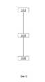
圖9說明根據一實施例的校準程序模型之例示性方法。Figure 9 illustrates an exemplary method of calibrating a program model according to one embodiment.
在一些實施例中,用於改良圖案化程序之程序模型的方法可包括:在910處獲得a)來自影像擷取裝置之經量測輪廓330,及b)由程序模型之模擬產生的經模擬輪廓510。In some embodiments, a method for improving a process model of a patterning process may include obtaining at 910 a) a measured
在920處,藉由判定經量測輪廓330與經模擬輪廓510之間的偏移610來對準經量測輪廓330與經模擬輪廓510。At 920 , the measured
在930處,校準程序模型以減小經模擬輪廓510與經量測輪廓330之間的基於經判定偏移610計算的差。At 930 , the program model is calibrated to reduce the difference between the
圖10說明根據一實施例的校準OPC模型之例示性方法。Figure 10 illustrates an exemplary method of calibrating an OPC model, according to one embodiment.
在一些實施例中,用於改良圖案化程序之光學近接校正(OPC)模型的方法可包括:在1010處獲得a)來自影像擷取裝置之經量測輪廓330,及b)由OPC模型之模擬產生的經模擬輪廓510。In some embodiments, a method for improving an optical proximity correction (OPC) model of a patterning process may include obtaining, at 1010, a) a measured
在1020處,藉由判定經量測輪廓330與經模擬輪廓510之間的偏移610來對準經量測輪廓330與經模擬輪廓510。At 1020 , the measured
在1030處,修改OPC模型之特徵以減小經模擬輪廓510與經量測輪廓330之間的基於經判定偏移610計算的差。At 1030 , the characteristics of the OPC model are modified to reduce the difference between the
圖11說明根據一實施例的獲取目標之多個影像及校準程序模型的例示性方法。11 illustrates an exemplary method of acquiring multiple images of a target and calibrating a procedural model, according to one embodiment.
在一些實施例中,用於改良圖案化程序之程序模型的方法可包括:在1110處獲得a)來自影像擷取裝置之多個經量測影像410,及b)由程序模型之模擬產生的經模擬輪廓510。In some embodiments, a method for improving a process model of a patterning process may include obtaining, at 1110, a) a plurality of measured
在1120處,對準多個經量測影像410。At 1120, the plurality of measured
在1130處,自經對準的多個量測影像410產生組合之經量測影像320。At 1130 , a combined measured
在1140處,藉由影像分析方法自組合之經量測影像320提取經量測輪廓330。At 1140, the measured
在1150處,藉由判定經量測輪廓330與經模擬輪廓510之間的偏移610來對準經量測輪廓330與經模擬輪廓510。At 1150, by determining the difference between the measured
在1160處,校準程序模型以減小經模擬輪廓510與經量測輪廓330之間的基於經判定偏移610計算的差。At 1160 , the program model is calibrated to reduce the difference between the
圖12為根據一實施例的實例度量系統之方塊圖。本文中所描述的實施例可實施於任何數目個計算系統、影像擷取裝置、伺服器及使用者介面及其組合上。一個例示性系統經說明於圖12中,其中集群1210(其可視情況含有串行及/或並行操作的任何數目個電腦)可經組態以允許選擇及傳輸EP座標630(在本文中亦被稱作EP量規630)。可將EP量規630傳輸至一或多個管理伺服器1220,其中可將工作程序1230發送至影像擷取裝置1240。工作程序1230可包括關於圖案化程序的資訊及亦包括用於影像擷取裝置1240之操作的指令。因此描述之例示性系統改良OPC預測準確度並減少OPC顯影循環時間。Figure 12 is a block diagram of an example metrology system, according to an embodiment. The embodiments described herein can be implemented on any number and combination of computing systems, image capture devices, servers, and user interfaces. An exemplary system is illustrated in FIG. 12, wherein a cluster 1210 (which may optionally contain any number of computers operating in series and/or parallel) may be configured to allow selection and transmission of EP coordinates 630 (also referred to herein as called EP gauge 630). The
圖13為根據一實施例的改良之度量衡程序的實例實施方式之程序流程圖。13 is a program flow diagram of an example implementation of an improved weights and measures program according to an embodiment.
根據本文中所描述之系統及實施例的用於改良度量之方法可包括:在計算集群(諸如集群1210)上執行程序模型。在1310處,程序模型可接受倍縮光罩設計。在1312處,程序模型可接著產生指定目標圖案之GDS佈局。在1314處,程序模型可接著選擇一或多個EP量規,例如參看圖6所描述。A method for improving metrics according to systems and embodiments described herein may include executing a program model on a computing cluster, such as
在1320處,影像擷取裝置(例如影像擷取裝置1240)可產生工作程序1230。工作程序1230可藉由影像擷取裝置1240使用以在1322處對印刷圖案執行高品質度量,包括產生任何數目個高解析度經量測影像。可將經量測影像傳輸至集群1210以進行影像處理。At 1320 , the image capture device (such as the image capture device 1240 ) can generate the
影像處理可包括例如在1330處執行影像濾波,1332處之影像對準及平均,1334處之輪廓提取,及1336處之EP量規提取。影像濾波可包括例如基於例如經准許基準或容許度自動移除誤印刷影像及/或低對比度影像。視情況,作為輪廓提取程序之部分,工作程序1230及經量測影像320可自1322輸入,以藉由在影像濾波之前及之後比較經量測影像320及平均對準程序來增加度量衡一致性。Image processing may include, for example, performing image filtering at 1330 , image alignment and averaging at 1332 , contour extraction at 1334 , and EP gauge extraction at 1336 . Image filtering may include, for example, automatically removing misprint images and/or low contrast images based on, for example, approved benchmarks or tolerances. Optionally, the working
可在1340處執行模型校準及驗證,其中在1336處提取的EP量規可藉由一或多個計算系統接收。經校準且經驗證之模型可在1340處經優化,以支援大量EP量規,例如相對於CD量規之數目增加2、3、3.6、5、10或更大之因數。在1342處,程序模型可經校準且在1344處,可將經校準之程序模型提供至圖形使用者介面(GUI)以供使用者審閱、改進、傳輸或進一步處理。Model calibration and validation can be performed at 1340, where the EP gauge extracted at 1336 can be received by one or more computing systems. The calibrated and validated model can be optimized at 1340 to support a large number of EP gauges, for example increased by a factor of 2, 3, 3.6, 5, 10 or more relative to the number of CD gauges. At 1342, the program model can be calibrated and at 1344, the calibrated program model can be provided to a graphical user interface (GUI) for user review, improvement, transmission, or further processing.
圖14為根據一實施例的實例電腦系統CS的方塊圖。FIG. 14 is a block diagram of an example computer system CS, according to an embodiment.
電腦系統CS包括用於傳達資訊之匯流排BS或其他通信機構,及與匯流排BS耦接以用於處理資訊之處理器PRO(或多個處理器)。電腦系統CS亦包括耦接至匯流排BS以用於儲存待由處理器PRO執行之資訊及指令的主記憶體MM,諸如隨機存取記憶體(RAM)或其他動態儲存裝置。主記憶體MM亦可用於在待由處理器PRO執行之指令的執行期間儲存暫時性變數或其他中間資訊。電腦系統CS進一步包括耦接至匯流排BS以用於儲存用於處理器PRO之靜態資訊及指令的唯讀記憶體(ROM)ROM或其他靜態儲存裝置。提供諸如磁碟或光碟之儲存裝置SD,且將其耦接至匯流排BS以用於儲存資訊及指令。Computer system CS includes a bus BS or other communication mechanism for communicating information, and a processor PRO (or processors) coupled to bus BS for processing information. The computer system CS also includes a main memory MM, such as random access memory (RAM) or other dynamic storage devices, coupled to the bus BS for storing information and instructions to be executed by the processor PRO. The main memory MM can also be used to store temporary variables or other intermediate information during the execution of instructions to be executed by the processor PRO. The computer system CS further includes a read only memory (ROM) ROM or other static storage device coupled to the bus BS for storing static information and instructions for the processor PRO. A storage device SD such as a magnetic or optical disk is provided and coupled to the bus BS for storing information and instructions.
電腦系統CS可經由匯流排BS耦接至用於向電腦使用者顯示資訊之顯示器DS,諸如陰極射線管(CRT)或平板顯示器或觸控面板顯示器。包括文數字按鍵及其他按鍵之輸入裝置ID耦接至匯流排BS以用於將資訊及命令選擇傳達至處理器PRO。另一類型之使用者輸入裝置為用於將方向資訊及命令選擇傳達至處理器PRO且用於控制顯示器DS上之游標移動的游標控制件CC,諸如滑鼠、軌跡球或游標方向按鍵。此輸入裝置通常具有在兩個軸-第一軸(例如x)及第二軸(例如y)中之兩個自由度,其允許該裝置指定平面中之位置。亦可將觸控面板(螢幕)顯示器用作輸入裝置。The computer system CS can be coupled via the bus bar BS to theA display DS for displaying information, such as a cathode ray tube (CRT) or a flat panel display or a touch panel display. Input devices ID including alphanumeric and other keys are coupled to the bus BS for communicating information and command selections to the processor PRO. Another type of user input device is a cursor control CC, such as a mouse, trackball or cursor direction keys, for communicating direction information and command selections to the processor PRO and for controlling movement of a cursor on the display DS. This input device typically has two degrees of freedom in two axes - a first axis (eg x) and a second axis (eg y) which allow the device to specify a position in a plane. A touch panel (screen) display can also be used as an input device.
根據一個實施例,本文中所描述之一或多種方法的部分可藉由電腦系統CS回應於處理器PRO執行主記憶體MM中所含有之一或多個指令的一或多個序列來執行。可將此等指令自另一電腦可讀媒體(諸如儲存裝置SD)讀取至主記憶體MM中。執行主記憶體MM中所含有之指令序列使得處理器PRO執行本文中所描述之程序步驟。亦可使用呈多處理配置之一或多個處理器來執行主記憶體MM中所含有之指令序列。在替代性實施例中,可代替或組合軟體指令而使用硬連線電路。因此,本文中之描述不限於硬體電路與軟體之任何具體組合。According to one embodiment, parts of one or more methods described herein may be performed by the computer system CS in response to the processor PRO executing one or more sequences of one or more instructions contained in the main memory MM. These instructions can be read from another computer-readable medium, such as a storage device SD, into the main memory MM. Execution of the instruction sequences contained in the main memory MM causes the processor PRO to execute the program steps described herein. One or more processors in a multi-processing configuration may also be used to execute the sequences of instructions contained in main memory MM. In alternative embodiments, hard-wired circuitry may be used instead of or in combination with software instructions. Thus, the descriptions herein are not limited to any specific combination of hardware circuitry and software.
如本文中所使用之術語「電腦可讀媒體」係指參與將指令提供至處理器PRO以供執行之任何媒體。此媒體可呈許多形式,包括但不限於非揮發性媒體、揮發性媒體及傳輸媒體。非揮發性媒體包括例如光碟或磁碟,諸如儲存裝置SD。揮發性媒體包括動態記憶體,諸如主記憶體MM。傳輸媒體包括同軸纜線、銅線及光纖,包括包含匯流排BS之導線。傳輸媒體亦可呈聲波或光波之形式,諸如在射頻(RF)及紅外線(IR)資料通信期間產生之聲波或光波。電腦可讀媒體可為非暫時性的,例如軟碟、可撓性磁碟、硬碟、磁帶、任何其他磁性媒體、CD-ROM、DVD、任何其他光學媒體、打孔卡、紙帶、具有孔圖案之任何其他實體媒體、RAM、PROM及EPROM、FLASH-EPROM、任何其他記憶體晶片或卡匣。非暫時性電腦可讀媒體可具有記錄於其上之指令。該等指令在由電腦執行時可實施本文中所描述的特徵中之任一者。暫時性電腦可讀媒體可包括載波或其他傳播電磁信號。The term "computer-readable medium" as used herein refers to any medium that participates in providing instructions to the processor PRO for execution. This medium can take many forms, including but not limited to, non-volatile media, volatile media, and transmission media. Non-volatile media include, for example, optical or magnetic disks, such as storage devices SD. Volatile media includes dynamic memory, such as main memory MM. Transmission media include coaxial cables, copper wires, and fiber optics, including wires including bus bars BS. Transmission media can also take the form of acoustic or light waves, such as those generated during radio frequency (RF) and infrared (IR) data communications. Computer readable media may be non-transitory, such as floppy disks, flexible disks, hard disks, tapes, any other magnetic media, CD-ROMs, DVDs, any otherOther optical media, punched cards, paper tape, any other physical media with a pattern of holes, RAM, PROM and EPROM, FLASH-EPROM, any other memory chips or cartridges. A non-transitory computer readable medium may have instructions recorded thereon. These instructions, when executed by a computer, can implement any of the features described herein. Transient computer readable media may include carrier waves or other propagating electromagnetic signals.
各種形式之電腦可讀媒體可涉及將一或多個指令之一或多個序列攜載至處理器PRO以供執行。舉例而言,最初可將該等指令承載於遠端電腦之磁碟上。遠端電腦可將指令載入至其動態記憶體中,且使用數據機經由電話線來發送指令。在電腦系統CS本端之數據機可接收電話線上之資料,且使用紅外線傳輸器將資料轉換成紅外線信號。耦接至匯流排BS之紅外線偵測器可接收紅外線信號中所攜載之資料且將資料置放於匯流排BS上。匯流排BS將資料攜載至主記憶體MM,處理器PRO自該主記憶體擷取且執行指令。由主記憶體MM接收之指令可視情況在由處理器PRO執行之前或之後儲存於儲存裝置SD上。Various forms of computer-readable media may be involved in carrying one or more sequences of one or more instructions to the processor PRO for execution. For example, the instructions may initially be carried on a disk in the remote computer. The remote computer can load the instructions into its dynamic memory and use a modem to send the instructions over a telephone line. The modem at the local end of the computer system CS can receive data on the telephone line, and use an infrared transmitter to convert the data into infrared signals. The infrared detector coupled to the bus bar BS can receive the data carried in the infrared signal and place the data on the bus bar BS. The bus BS carries the data to the main memory MM, from which the processor PRO retrieves and executes instructions. The instructions received by the main memory MM are optionally stored on the storage device SD before or after their execution by the processor PRO.
電腦系統CS亦可包括耦接至匯流排BS之通信介面CI。通信介面CI提供與網路鏈路NDL之雙向資料通信耦合,該網路鏈路連接至區域網路LAN。舉例而言,通信介面CI可為整合服務數位網路(ISDN)卡或數據機以提供與對應類型之電話線的資料通信連接。作為另一實例,通信介面CI可為區域網路(LAN)卡以提供與相容LAN的資料通信連接。亦可實施無線鏈路。在任何此實施方式中,通信介面CI發送且接收攜載表示各種類型之資訊的數位資料串流之電信號、電磁信號或光信號。The computer system CS may also include a communication interface CI coupled to the bus BS. The communication interface CI provides a bidirectional data communication coupling with the network link NDL connected to the local area network LAN. For example, the communication interface CI may be an Integrated Services Digital Network (ISDN) card or a modem to provide a data communication connection with a corresponding type of telephone line. As another example, the communication interface CI may be an area network (LAN) card to provide a data communication connection with a compatible LAN. Wireless links may also be implemented. In any such implementation, the communication interface CI sends and receives electrical, electromagnetic or optical signals that carry digital data streams representing various types of information.
網路鏈路NDL通常經由一或多個網路將資料通信提供至其他資料裝置。舉例而言,網路鏈路NDL可經由區域網路LAN將連接提供至主電腦HC。此可包括經由全球封包資料通信網路(現在通常被稱作「網際網路」INT)而提供之資料通信服務。區域網路LAN(網際網路)皆使用攜載數位資料串流之電信號、電磁信號或光信號。經由各種網路之信號及在網路資料鏈路NDL上且經由通信介面CI之信號為輸送資訊的例示性形式之載波,該等信號將數位資料攜載至電腦系統CS且自電腦系統CS攜載數位資料。A network link NDL typically provides data communication to other data devices via one or more networks. For example, a network link NDL can provide connectivity via a local area network LANto the main computer HC. This may include data communication services provided over the global packet data communication network (now commonly referred to as the "Internet" INT). Local Area Networks (LAN) (Internet) all use electrical, electromagnetic or optical signals that carry digital data streams. The signals via the various networks and the signals on the network data link NDL and via the communication interface CI are carrier waves which carry exemplary forms of information, which carry digital data to and from the computer system CS. Upload digital data.
電腦系統CS可經由網路、網路資料鏈路NDL及通信介面CI發送訊息及接收資料(包括程式碼)。在網際網路實例中,主電腦HC可經由網際網路INT、網路資料鏈路NDL、區域網路LAN及通信介面CI傳輸用於應用程式之經請求程式碼。舉例而言,一個此經下載應用程式可提供本文中所描述之方法的全部或部分。所接收程式碼可在其被接收時由處理器PRO執行,及/或儲存於儲存裝置SD或其他非揮發性儲存器中以供稍後執行。以此方式,電腦系統CS可獲得呈載波形式之應用程式碼。The computer system CS can send messages and receive data (including codes) via the network, the network data link NDL and the communication interface CI. In the Internet example, the host computer HC can transmit the requested code for the application via the Internet INT, the network data link NDL, the local area network LAN and the communication interface CI. For example, one such downloaded application can provide all or part of the methods described herein. The received program code can be executed by the processor PRO as it is received and/or stored in a storage device SD or other non-volatile memory for later execution. In this way, the computer system CS can obtain the application code in the form of a carrier wave.
圖15為根據一實施例的微影投影設備之示意圖。FIG. 15 is a schematic diagram of a lithography projection apparatus according to an embodiment.
微影投影設備可包括照明系統IL、第一物件台MT、第二物件台WT及投影系統PS。The lithography projection apparatus may include an illumination system IL, a first object stage MT, a second object stage WT, and a projection system PS.
照明系統IL可調節輻射光束B。在此特定情況下,照明系統亦包含輻射源SO。The illumination system IL can adjust the radiation beam B. In this particular case, the lighting system also comprises the radiation source SO.
第一物件台(例如圖案化裝置台)MT可設置有用以固持圖案化裝置MA(例如倍縮光罩)之圖案化裝置固持器,且連接至用以相對於項目PS來準確地定位圖案化裝置之第一定位器。A first object stage (e.g., patterning device stage) MT may be provided with a patterning device holder for holding a patterning device MA (e.g., a reticle) and connected to a patterning device for accurately positioning the patterning device relative to the item PS. The first locator of the device.
第二物件台(基板台)WT可設置有用以固持基板W(例如抗蝕劑塗佈矽晶圓)之基板固持器,且連接至用以相對於項目PS準確地定位基板之第二定位器。A second object table (substrate table) WT may be provided with a substrate holder for holding a substrate W, such as a resist-coated silicon wafer, and be connected to an object for accurate positioning relative to the item PS.The second positioner of the substrate.
投影系統(「透鏡」)PS(例如折射、反射或反射折射光學系統)可將圖案化裝置MA之經輻照部分成像至基板W之目標部分C(例如包含一或多個晶粒)上。A projection system ("lens") PS (eg, a refractive, reflective, or catadioptric optical system) may image the irradiated portion of the patterning device MA onto a target portion C of the substrate W (eg, comprising one or more dies).
如本文中所描繪,設備可屬於透射型(亦即,具有透射圖案化裝置)。然而,大體而言,其亦可屬於例如反射型(具有反射圖案化裝置)。設備可使用與經典光罩不同種類之圖案化裝置;實例包括可程式化鏡面陣列或LCD矩陣。As depicted herein, the apparatus may be of the transmissive type (ie, have a transmissive patterning device). In general, however, it can also be eg reflective (with reflective patterning means). Devices may use different kinds of patterning devices than classical reticles; examples include programmable mirror arrays or LCD matrices.
源SO(例如水銀燈或準分子雷射、雷射產生電漿(LPP)EUV源)產生輻射光束。舉例而言,直接地抑或在已橫穿諸如光束擴展器Ex之調節構件之後將此光束饋入至照明系統(照明器)IL中。照明器IL可包含調整構件AD以用於設定光束中之強度分佈之外部徑向範圍及/或內部徑向範圍(通常分別被稱作σ外部及σ內部)。另外,照明器IL通常將包含各種其他組件,諸如積光器IN及聚光器CO。以此方式,照射於圖案化裝置MA上之光束B在其橫截面中具有所要均一性及強度分佈。A source SO, such as a mercury lamp or an excimer laser, a laser-produced plasma (LPP) EUV source, produces a beam of radiation. For example, this light beam is fed into the illumination system (illuminator) IL either directly or after having traversed an adjustment member such as a beam expander Ex. The illuminator IL may comprise adjustment means AD for setting the outer radial extent and/or the inner radial extent (commonly referred to as σouter and σinner, respectively) of the intensity distribution in the light beam. Additionally, the illuminator IL will typically include various other components, such as an integrator IN and a condenser CO. In this way, the beam B impinging on the patterning device MA has the desired uniformity and intensity distribution in its cross-section.
在一些實施例中,源SO可在微影投影設備之殼體內(如常常為當源SO為例如水銀燈時的情況),但其亦可遠離微影投影設備,源SO產生之輻射光束(例如藉助於合適的導向鏡)經引導至設備中;此後一情形可為當源SO為準分子雷射(例如基於KrF、ArF或F2發出雷射)時的情況。In some embodiments, the source SO may be within the housing of the lithographic projection apparatus (as is often the case when the source SO is, for example, a mercury lamp), but it may also be remote from the lithographic projection apparatus, the source SO producing a beam of radiation (e.g. is guided into the device by means of suitable guiding mirrors); this latter case may be the case when the source SO is an excimer laser, for example emitting a laser based on KrF, ArF or F2.
光束PB可隨後截取固持於圖案化裝置台MT上之圖案化裝置MA。橫穿圖案化裝置MA後,光束B可穿過透鏡PL,透鏡PL將光束B聚焦至基板W之目標部分C上。藉助於第二定位構件(及干涉量測構件IF),可準確地移動基板台WT(例如)以便使不同目標部分C定位於光束PB之路徑中。類似地,第一定位構件可用於例如在自圖案化裝置庫機械擷取圖案化裝置MA之後或在掃描期間相對於光束B之路徑來準確地定位圖案化裝置MA。大體而言,可藉助於長衝程模組(粗略定位)及短衝程模組(精細定位)來實現物件台MT、WT之移動。然而,在步進器(與步進掃描工具相反)之情況下,圖案化裝置台MT可僅連接至短衝程致動器,或可經固定。The beam PB may then intercept the patterning device MA held on the patterning device table MT. After traversing the patterning device MA, the beam B may pass through the lens PL, which focuses the beam B onto the target portion C of the substrate W. By means of the second positioning means (and the interferometric means IF), the substrate table WT can be accurately moved, for example, in order to position different target portions C in the path of the beam PBin the path. Similarly, the first positioning means may be used to accurately position the patterning device MA relative to the path of the beam B, for example after mechanical retrieval of the patterning device MA from the patterning device library or during scanning. Generally speaking, the movement of the object tables MT, WT can be realized by means of long-stroke modules (coarse positioning) and short-stroke modules (fine positioning). However, in the case of a stepper (as opposed to a step-and-scan tool), the patterning device table MT may only be connected to a short-stroke actuator, or may be fixed.
可在兩種不同模式(步進模式及掃描模式)下使用所描繪工具。在步進模式下,使圖案化裝置台MT保持基本上靜止,且將整個圖案化裝置影像一次性(亦即,單次「閃光」)投影至目標部分C上。可使基板台WT在x及/或y方向上移位,使得不同目標部分C可由光束PB輻照。The depicted tool can be used in two different modes, step mode and sweep mode. In step mode, the patterning device table MT is held substantially stationary, and the entire patterning device image is projected onto the target portion C in one go (ie, a single "flash"). The substrate table WT can be displaced in the x and/or y direction so that different target portions C can be irradiated by the beam PB.
在掃描模式下,除了不在單次「閃光」中曝光給定目標部分C之外,基本上相同的情形適用。實際上,圖案化裝置台MT可在給定方向(所謂的「掃描方向」,例如y方向)上以速度v移動,以使得使投影光束B在圖案化裝置影像上進行掃描;同時,基板台WT以速度V=Mv在相同或相反方向上同時地移動,其中M為透鏡PL之放大率(通常,M=1/4或1/5)。以此方式,可在不必損害解析度之情況下曝光相對較大之目標部分C。In scan mode, essentially the same applies except that a given target portion C is not exposed in a single "flash". In practice, the patterning device table MT can be moved with a velocity v in a given direction (the so-called "scanning direction", e.g. the y-direction) such that the projection beam B is scanned on the patterning device image; at the same time, the substrate table The WT moves simultaneously in the same or opposite directions at a velocity V=Mv, where M is the magnification of the lens PL (typically, M=1/4 or 1/5). In this way, a relatively large target portion C can be exposed without compromising resolution.
圖16為根據一實施例的另一微影投影設備(LPA)的示意圖。FIG. 16 is a schematic diagram of another lithography projection apparatus (LPA) according to an embodiment.
LPA可包括源收集器模組SO、經組態以調節輻射光束B(例如EUV輻射)之照明系統(照明器)IL、支撐結構MT、基板台WT及投影系統PS。The LPA may include a source collector module SO, an illumination system (illuminator) IL configured to condition a radiation beam B (eg, EUV radiation), a support structure MT, a substrate table WT, and a projection system PS.
支撐結構(例如圖案化裝置台)MT可經建構以支撐圖案化裝置(例如光罩或倍縮光罩)MA,且連接至經組態以準確地定位圖案化裝置之第一定位器PM。A support structure (such as a patterning device table) MT can be constructed to support a patterning device (such as a reticle or reticle) MA and connected to a patterning device configured to accurately position the patterning device.Set the first locator PM.
基板台(例如晶圓台)WT可經建構以固持基板(例如抗蝕劑塗佈晶圓)W,且連接至經組態以準確地定位該基板之第二定位器PW。A substrate table (eg, wafer table) WT may be constructed to hold a substrate (eg, resist coated wafer) W and connected to a second positioner PW configured to accurately position the substrate.
投影系統(例如反射性投影系統)PS可經組態以將藉由圖案化裝置MA向輻射光束B賦予之圖案投影至基板W之目標部分C(例如包含一或多個晶粒)上。The projection system (eg reflective projection system) PS may be configured to project the pattern imparted to the radiation beam B by the patterning device MA onto a target portion C of the substrate W (eg comprising one or more dies).
如此處所描繪,LPA可屬於反射型(例如採用反射圖案化裝置)。應注意,由於大多數材料在EUV波長範圍內具吸收性,因此圖案化裝置可具有包含例如鉬與矽之多堆疊的多層反射器。在一個實例中,多堆疊反射器具有鉬與矽之40個層對,其中每一層之厚度為四分之一波長。可用X射線微影來產生甚至更小之波長。由於大多數材料在EUV及x射線波長下具吸收性,因此圖案化裝置構形上的經圖案化吸收材料之薄件(例如在多層反射器的頂部上之TaN吸收體)界定特徵將印刷(正型抗蝕劑)或不印刷(負型抗蝕劑)之位置。As depicted here, the LPA can be of the reflective type (eg, employing a reflective patterning device). It should be noted that since most materials are absorptive in the EUV wavelength range, the patterned device may have multilayer reflectors comprising multiple stacks of molybdenum and silicon, for example. In one example, a multi-stack reflector has 40 layer pairs of molybdenum and silicon, where each layer is a quarter wavelength thick. Even smaller wavelengths can be produced using X-ray lithography. Since most materials are absorbing at EUV and x-ray wavelengths, a thin piece of patterned absorbing material on a patterned device topography (such as a TaN absorber on top of a multilayer reflector) defining features will print ( positive resist) or not printed (negative resist).
照明器IL可自源收集器模組SO接收極紫外線輻射光束。用以產生EUV輻射之方法包括但不一定限於用EUV範圍中之一或多個發射譜線將材料轉換成具有至少一個元素(例如氙、鋰或錫)之電漿狀態。在一種此方法(常常被稱為雷射產生電漿(「LPP」))中,可藉由用雷射光束來輻照燃料(諸如具有譜線發射元素之材料的小滴、串流或集群)而產生電漿。源收集器模組SO可為包括雷射(圖11中未展示)的EUV輻射系統之部分,該雷射用於提供激發燃料之雷射光束。所得電漿發射輸出輻射(例如EUV輻射),使用安置於源收集器模組中之輻射收集器來收集該輻射。舉例而言,當使用CO2雷射以提供用於燃料激發之雷射光束時,雷射與源收集器模組可為分離的實體。The illuminator IL may receive a beam of EUV radiation from the source collector module SO. Methods to generate EUV radiation include, but are not necessarily limited to, converting a material into a plasma state with at least one element such as xenon, lithium, or tin with one or more emission lines in the EUV range. In one such method, often referred to as laser-produced plasma ("LPP"), fuel (such as droplets, streams, or clusters of material with line-emitting elements) is irradiated with a laser beam. ) to generate plasma. The source collector module SO may be part of an EUV radiation system including a laser (not shown in FIG. 11 ) for providing a laser beam that excites the fuel. The resulting plasma emits output radiation, such as EUV radiation, which is collected using a radiation collector disposed in the source collector module. For example, when aCO2 laser is used to provide a laser beam for fuel excitation, the laser and source collector module may be separate entities.
在此等情況下,雷射可不被視為形成微影設備之部分,且輻射光束可藉助於包含例如合適的導向鏡及/或光束擴展器之光束遞送系統而自雷射傳遞至源收集器模組。在其他情況下,舉例而言,當源為放電產生電漿EUV產生器(常常被稱為DPP源)時,源可為源收集器模組之整體部分。In such cases, the laser may not be considered to form part of the lithography apparatus, and the radiation beam may be delivered from the laser to the source collector by means of a beam delivery system comprising, for example, suitable steering mirrors and/or beam expanders mod. In other cases, for example when the source is a discharge produced plasma EUV generator (often referred to as a DPP source), the source may be an integral part of the source collector module.
照明器IL可包含用於調整輻射光束之角強度分佈之調整器。大體而言,可調整照明器之光瞳平面中之強度分佈的至少外部徑向範圍及/或內部徑向範圍(通常分別被稱作σ外部及σ內部)。另外,照明器IL可包含各種其他組件,諸如琢面化場鏡面裝置及琢面化光瞳鏡面裝置。照明器可用於調節輻射光束,以在其橫截面中具有所要均一性及強度分佈。The illuminator IL may comprise an adjuster for adjusting the angular intensity distribution of the radiation beam. In general, at least the outer radial extent and/or the inner radial extent (commonly referred to as σouter and σinner, respectively) of the intensity distribution in the pupil plane of the illuminator can be adjusted. In addition, the illuminator IL may include various other components, such as faceted field mirror devices and faceted pupil mirror devices. The illuminator can be used to condition the radiation beam to have a desired uniformity and intensity distribution in its cross-section.
輻射光束B可入射於固持於支撐結構(例如圖案化裝置台)MT上之圖案化裝置(例如光罩)MA上且藉由圖案化裝置圖案化。在自圖案化裝置(例如光罩)MA反射之後,輻射光束B穿過投影系統PS,該投影系統將光束聚焦至基板W之目標部分C上。藉助於第二定位器PW及位置感測器PS2(例如干涉量測裝置、線性編碼器或電容式感測器),可準確地移動基板台WT,例如以便使不同目標部分C定位於輻射光束B之路徑中。類似地,第一定位器PM及另一位置感測器PS1可用於相對於輻射光束B之路徑準確地定位圖案化裝置(例如光罩)MA。可使用圖案化裝置對準標記M1、M2及基板對準標記P1、P2來對準圖案化裝置(例如光罩)MA及基板W。The radiation beam B may be incident on a patterning device (eg a reticle) MA held on a support structure (eg a patterning device table) MT and patterned by the patterning device. After reflection from the patterning device (eg a reticle) MA, the radiation beam B passes through a projection system PS which focuses the beam onto a target portion C of the substrate W. By means of a second positioner PW and a position sensor PS2 (e.g. an interferometric device, a linear encoder or a capacitive sensor), the substrate table WT can be moved precisely, e.g. in order to position different target portions C in the radiation beam in the path of B. Similarly, the first positioner PM and the further position sensor PS1 can be used to accurately position the patterning device (eg reticle) MA relative to the path of the radiation beam B. Patterning device (eg, photomask) MA and substrate W may be aligned using patterning device alignment marks M1 , M2 and substrate alignment marks P1 , P2 .
所描繪設備LPA可用於以下模式中之至少一者:步進模式、掃描模式及靜止模式。The depicted apparatus LPA can be used in at least one of the following modes: stepping mode, scanning mode, and stationary mode.
在步進模式下,使支撐結構(例如圖案化裝置台)MT及基板台WT保持基本上靜止,同時將向輻射光束賦予之整個圖案一次性(亦即,單次靜態曝光)投影至目標部分C上。接著,使基板台WT在X及/或Y方向上移位,以使得可曝光不同目標部分C。In step mode, the support structure (e.g., patterning device table) MT and substrate table WT are held substantially stationary while the entire pattern imparted to the radiation beam is projected onto the target portion in one go (i.e., a single static exposure) on C. Next, the substrate table WT is shifted in the X and/or Y direction so that different target portions C can be exposed.
在掃描模式下,同步地掃描支撐結構(例如圖案化裝置台)MT及基板台WT,同時將向輻射光束賦予之圖案投影至目標部分C上(亦即,單次動態曝光)。可藉由投影系統PS之放大率(縮小率)及影像反轉特性來判定基板台WT相對於支撐結構(例如圖案化裝置台)MT之速度及方向。In scanning mode, the support structure (eg patterning device table) MT and substrate table WT are scanned synchronously while projecting the pattern imparted to the radiation beam onto the target portion C (ie a single dynamic exposure). The velocity and direction of the substrate table WT relative to the support structure (eg, patterning device table) MT can be determined by the magnification (reduction) and image inversion characteristics of the projection system PS.
在靜止模式下,使支撐結構(例如圖案化裝置台)MT保持基本上靜止從而固持可程式化圖案化裝置,且移動或掃描基板台WT,同時將向輻射光束賦予之圖案投射至目標部分C上。在此模式下,通常使用脈衝式輻射源,且在基板台WT之每一移動之後或在掃描期間之順次輻射脈衝之間視需要而更新可程式化圖案化裝置。此操作模式可易於應用於利用可程式化圖案化裝置(諸如上文所提及之類型之可程式化鏡面陣列)之無光罩微影。In stationary mode, the support structure (e.g., patterning device table) MT is held substantially stationary to hold the programmable patterning device, and the substrate table WT is moved or scanned while projecting a pattern imparted to the radiation beam onto the target portion C superior. In this mode, a pulsed radiation source is typically used, and the programmable patterning device is refreshed as needed after each movement of the substrate table WT or between successive radiation pulses during a scan. This mode of operation is readily applicable to maskless lithography utilizing programmable patterning devices such as programmable mirror arrays of the type mentioned above.
圖17為根據一實施例的微影投影設備之詳細視圖。Figure 17 is a detailed view of a lithography projection apparatus according to an embodiment.
如所展示,LPA可包括源收集器模組SO、照明系統IL及投影系統PS。源收集器模組SO經建構及配置成使得可將真空環境維持於源收集器模組SO之圍封結構220中。可藉由放電產生電漿源來形成EUV輻射發射電漿210。可藉由氣體或蒸汽(例如Xe氣體、Li蒸汽或Sn蒸汽)來產生EUV輻射,其中產生極熱電漿210以發射在電磁光譜的EUV範圍內之輻射。舉例而言,藉由產生至少部分地離子化電漿之放電來產生極熱電漿210。為了輻射之高效產生,可能需要例如10Pa之分壓的Xe、Li、Sn蒸汽或任何其他合適的氣體或蒸汽。在一實施例中,提供受激發錫(Sn)電漿以產生EUV輻射。As shown, the LPA may include a source collector module SO, an illumination system IL, and a projection system PS. The source collector module SO is constructed and arranged such that a vacuum environment can be maintained within the
由熱電漿210發射之輻射經由定位於源腔室211中之開口中或後方的視情況選用之氣體障壁或污染物截留器230(在一些情況下,亦被稱作污染物障壁或箔片截留器)而自源腔室211傳遞至收集器腔室212中。污染物截留器230可包括通道結構。污染物截留器230亦可包括氣體障壁或氣體障壁與通道結構之組合。如此項技術中所知,本文中進一步指示之污染物截留器或污染物障壁230至少包括通道結構。Radiation emitted by
收集器腔室211可包括可為所謂的掠入射收集器之輻射收集器CO。輻射收集器CO具有上游輻射收集器側251及下游輻射收集器側252。橫穿收集器CO之輻射可自光柵光譜濾波器240反射,以沿著由點虛線「O」指示之光軸而聚焦於虛擬源點IF中。虛擬源點IF通常被稱作中間焦點,且源收集器模組經配置成使得中間焦點IF位於圍封結構220中之開口221處或附近。虛擬源點IF為輻射發射電漿210之影像。The
隨後,輻射橫穿照明系統IL,該照明系統可包括琢面化場鏡面裝置22及琢面化光瞳鏡面裝置24,琢面化場鏡面裝置及琢面化光瞳鏡面裝置經配置以提供在圖案化裝置MA處的輻射光束21之所要角分佈,以及在圖案化裝置MA處的輻射強度之所要均一性。在由支撐結構MT固持之圖案化裝置MA處反射輻射光束21後,形成經圖案化光束26,且經圖案化光束26藉由投影系統PS經由反射元件28、30成像至由基板台WT固持之基板W上。The radiation then traverses an illumination system IL, which may include a faceted
比所展示元件更多之元件通常可存在於照明光學件單元IL及投影系統PS中。視微影設備之類型而定,可視情況存在光柵光譜濾波器240。此外,可存在比諸圖中所展示之鏡面更多的鏡面,例如,在投影系統PS中可存在比圖12中所展示之反射元件多1至6個的額外反射元件。Many more elements than shown may typically be present in an illumination optics unit ILAnd projection system PS. Depending on the type of lithography apparatus, a grating
如圖12中所說明之收集器光學件CO經描繪為具有掠入射反射器253、254及255之巢套式收集器,僅僅作為收集器(或收集器鏡面)之實例。掠入射反射器253、254及255經安置為圍繞光軸O軸向對稱,且此類型之收集器光學件CO可與常常被稱為DPP源之放電產生電漿源組合使用。Collector optics CO as illustrated in FIG. 12 are depicted as nested collectors with
圖18為根據一實施例的微影投影設備LPA之源收集器模組SO的詳細視圖。FIG. 18 is a detailed view of the source collector module SO of the lithography projection apparatus LPA according to one embodiment.
源收集器模組SO可為LPA輻射系統之部分。雷射LA經配置以將雷射能量沈積至諸如氙(Xe)、錫(Sn)或鋰(Li)之燃料中,從而產生具有數十電子伏特(eV)的電子溫度之高度離子化電漿210。在此等離子之去激發及再結合期間所產生之高能輻射自電漿發射,由近正入射收集器光學件CO收集,且聚焦至圍封結構220中之開口221上。The source collector module SO may be part of the LPA radiation system. The laser LA is configured to deposit laser energy into a fuel such as xenon (Xe), tin (Sn) or lithium (Li), resulting in a highly ionized plasma with an electron temperature of tens of electron volts (eV) 210. The energetic radiation generated during the de-excitation and recombination of this plasma is emitted from the plasma, collected by near normal incidence collector optics CO, and focused onto
本文中所揭示之概念可模擬或在數學上模型化用於使子波長特徵成像之任何通用成像系統,且可尤其供能夠產生愈來愈短波長之新興成像技術使用。已經在使用中之新興技術包括極紫外線(EUV)、DUV微影,其能夠藉由使用ArF雷射來產生193nm之波長,且甚至能夠藉由使用氟雷射來產生157nm之波長。此外,EUV微影能夠藉由使用同步加速器或藉由用高能電子撞擊材料(固體或電漿中任一者)來產生在20nm至50nm之範圍內的波長,以便產生在此範圍內之光子。The concepts disclosed herein can simulate or mathematically model any general-purpose imaging system for imaging sub-wavelength features, and are especially useful for emerging imaging technologies capable of producing ever shorter and shorter wavelengths. Emerging technologies already in use include extreme ultraviolet (EUV), DUV lithography, which can produce wavelengths of 193nm by using ArF lasers, and even 157nm by using fluorine lasers. Furthermore, EUV lithography can produce wavelengths in the range of 20nm to 50nm by using synchrotrons or by impacting materials (either solid or plasma) with energetic electrons to generate photons in this range.
圖19示意性地描繪根據一實施例的電子束檢測設備1920之實施例。在一實施例中,檢測設備可為得到曝光或轉印於基板上之結構(例如裝置(諸如積體電路)之某一結構或全部結構)之影像的電子束檢測設備(例如與掃描電子顯微鏡(SEM)相同或類似)。自電子源1922發射之初級電子束1924由聚光器透鏡1926會聚,且接著穿過光束偏轉器1928、E×B偏轉器1930及物鏡1932以在焦點下輻照基板台1912上之基板1910。FIG. 19 schematically depicts an electron
當用電子束1924輻照基板1910時,由基板1910產生二次電子。該等二次電子由E×B偏轉器1930偏轉且由二次電子偵測器1934偵測。二維電子束影像可藉由與以下操作同步地偵測自樣本產生之電子而獲得:例如藉由光束偏轉器1928來二維掃描電子束或藉由光束偏轉器1928在X或Y方向上重複掃描電子束1924,以及藉由基板台1912在X或Y方向中之另一者上連續移動基板1910。因此,在一實施例中,電子束檢測設備具有用於由角程界定之電子束的視場,電子束可由電子束檢測設備提供至該角程(例如偏轉器1928可藉以提供電子束1924之角程)中。因此,該視場之空間範圍為電子束之角程可照射於表面上所達之空間範圍(其中該表面可為靜止的或可相對於該場移動)。When the
藉由類比/數位(A/D)轉換器1936將由二次電子偵測器1934偵測到之信號轉換成數位信號,且將該數位信號發送至影像處理系統1950。在一實施例中,影像處理系統1950可具有用以儲存供處理單元1958處理之全部或部分數位影像之記憶體1956。處理單元1958(例如經專門設計之硬體或硬體與軟體之組合或包含軟體之電腦可讀媒體)經組態以將數位影像轉換或處理成表示數位影像之資料集。在一實施例中,處理單元1958經組態或經程式化以促使執行本文中所描述之方法。此外,影像處理系統1950可具有經組態以將數位影像及對應資料集儲存於參考資料庫中之儲存媒體1956。顯示裝置1954可與影像處理系統1950連接,使得操作者可藉助於圖形使用者介面進行裝備之必要操作。The signal detected by the
圖20示意性地說明根據一實施例的檢測設備之另一實施例。該系統用於檢測樣本載物台89上之樣本90(諸如基板)且包含帶電粒子束產生器81、聚光器透鏡模組82、探針形成物鏡模組83、帶電粒子束偏轉模組84、二次帶電粒子偵測器模組85及影像形成模組86。Fig. 20 schematically illustrates another embodiment of a detection apparatus according to an embodiment. The system is used to detect a sample 90 (such as a substrate) on a
帶電粒子束產生器81產生初級帶電粒子束91。聚光器透鏡模組82將所產生之初級帶電粒子束91聚光。探針形成物鏡模組83將經聚光初級帶電粒子束聚焦成帶電粒子束探針92。帶電粒子束偏轉模組84在緊固於樣本載物台89上之樣本90上的所關注區域之表面上掃描所形成之帶電粒子束探針92。在一實施例中,帶電粒子束產生器81、聚光器透鏡模組82及探針形成物鏡模組83或其等效設計、替代方案或其任何組合一起形成產生掃描帶電粒子束探針92之帶電粒子束探針產生器。The charged
二次帶電粒子偵測器模組85偵測在由帶電粒子束探針92轟擊後即自樣本表面發射的二次帶電粒子93(亦可能與來自樣本表面之其他反射或散射帶電粒子一起),以產生二次帶電粒子偵測信號94。影像形成模組86(例如計算裝置)與二次帶電粒子偵測器模組85耦接以自二次帶電粒子偵測器模組85接收二次帶電粒子偵測信號94,且相應地形成至少一個掃描影像。在一實施例中,二次帶電粒子偵測器模組85及影像形成模組86或其等效設計、替代方案或其任何組合一起形成由帶電粒子束探針92轟擊的自樣本90發射的偵測到之二次帶電粒子形成掃描影像的影像形成設備。Secondary charged
在一實施例中,監測模組87耦接至影像形成設備之影像形成模組86以對圖案化程序進行監測、控制等,及/或使用自影像形成模組86接收到之樣本90的掃描影像來導出用於圖案化程序設計、控制、監測等的參數。因此,在一實施例中,監測模組87經組態或經程式化以促使執行本文中所描述之方法。在一實施例中,監測模組87包含計算裝置。在一實施例中,監測模組87包含用以提供本文中之功能性且經編碼於形成監測模組87或安置於該監測模組內的電腦可讀媒體上之電腦程式。In one embodiment, the
在一實施例中,與圖19之使用探針來檢測基板之電子束檢測工具類似,與例如CD SEM(諸如圖19中所描繪)相比,圖20之系統中之電子電流顯著較大,使得探針光點足夠大以使得檢測速度可較快。然而,由於探針光點較大,因此解析度可能不與CD SEM之解析度一樣高。In one embodiment, similar to the e-beam inspection tool of FIG. 19 that uses a probe to inspect a substrate, the electron current in the system of FIG. 20 is significantly larger compared to, for example, a CD SEM such as depicted in FIG. Make the probe spot large enough so that the detection speed can be fast. However, due to the larger probe spot, the resolution may not be as high as that of a CD SEM.
可處理來自例如圖19及/或圖20之系統的SEM影像以提取影像中描述表示裝置結構之物件之邊緣的輪廓。接著通常在使用者定義之切線處經由諸如CD之度量量化此等輪廓。因此,通常經由度量(諸如在經提取輪廓上量測之邊緣間距離(CD)或影像之間的簡單像素差)來比較且量化裝置結構之影像。可替代地,度量可包括如本文中所描述之EP量規。SEM images from systems such as FIG. 19 and/or FIG. 20 can be processed to extract contours in the images that describe the edges of objects representing device structures. These profiles are then quantified via a metric such as CD, typically at user-defined tangents. Thus, images of device structures are typically compared and quantified via metrics such as edge-to-edge distance (CD) measured on extracted contours or simple pixel differences between images. Alternatively, the metric may include an EP gauge as described herein.
現在,除了在圖案化程序中量測基板之外,亦常常需要使用一或多個工具來產生例如可用於對圖案化程序進行設計、控制、監測等之結果。為進行此操作,可提供用於對圖案化程序之一或多個態樣進行計算上控制、設計等的一或多個工具,諸如用於圖案化裝置之圖案設計(包括例如添加子解析度輔助特徵或光學近接校正)、用於圖案化裝置之照明等。因此,在用於對涉及圖案化之製造程序進行計算上控制、設計等之系統中,主要製造系統組件及/或程序可由各種功能模組描述。特定而言,在一實施例中,可提供描述圖案化程序之一或多個步驟及/或設備(通常包括圖案轉印步驟)的一或多個數學模型。在一實施例中,可使用一或多個數學模型來執行圖案化程序之模擬,以模擬圖案化程序如何使用由圖案化裝置提供之經量測或設計圖案來形成經圖案化基板。Now, in addition to measuring the substrate during the patterning process, it is often necessary to use one or more tools to produce results that can be used, for example, to design, control, monitor, etc. the patterning process. To do so, one or more tools may be provided for computationally controlling, designing, etc., one or more aspects of the patterning process, such as pattern design for a patterning device (including, for example, adding sub-resolution assist feature or optical proximity correction), illumination for patterning devices, etc. Thus, in a system for computationally controlling, designing, etc., manufacturing processes involving patterning, major manufacturing system components and/or processes may be described by various functional modules. In particular, in one embodiment, a description of one or more steps and/or equipment of the patterning process (typically includingOne or more mathematical models including the pattern transfer step). In one embodiment, a simulation of the patterning process may be performed using one or more mathematical models to simulate how the patterning process forms a patterned substrate using measured or designed patterns provided by a patterning device.
雖然本文中所揭示之概念可用於在諸如矽晶圓之基板上成像,但應理解,所揭示之概念可與任何類型之微影成像系統一起使用,例如用於在不同於矽晶圓的基板上成像的彼等微影成像系統。Although the concepts disclosed herein can be used for imaging on substrates such as silicon wafers, it should be understood that the concepts disclosed can be used with any type of lithographic imaging system, for example for imaging on substrates other than silicon wafers Their lithography imaging systems for imaging.
本文中之描述意欲為說明性的,而非限制性的。因此,對於熟習此項技術者將顯而易見,可在不脫離下文所闡明之申請專利範圍之範疇的情況下如所描述一般進行修改。The descriptions herein are intended to be illustrative, not limiting. Accordingly, it will be apparent to those skilled in the art that modifications may be made as generally described without departing from the scope of the claims set forth below.
圖21為說明根據一實施例的印刷圖案的原始影像及平均影像之圖式。21 is a diagram illustrating an original image and an average image of a printed pattern according to one embodiment.
此外,本發明描述獲取及分析印刷圖案之大量影像以執行作為微影程序之部分的高品質度量衡。如圖21中所說明,平均影像2110(左上方所展示)可展現比原始影像2120(右上方所展示)更清晰界定之結構。可量化此差之方式的實例藉由如以下影像所展示的信雜比之兩個曲線圖(2130、2140)進行說明。在兩個曲線圖中,可在與上述影像(2110、2120)中呈現之特徵的邊緣大體對應時看到信雜比之波峰。然而,比較兩個曲線圖表明對應於原始影像2120之曲線圖2140含有增大之雜訊,而對應於平均影像2110之曲線圖2130具有減小之雜訊等級。In addition, the present invention describes acquiring and analyzing large numbers of images of printed patterns to perform high quality metrology as part of the lithography process. As illustrated in Figure 21, the averaged image 2110 (shown at top left) may exhibit more clearly defined structures than the original image 2120 (shown at top right). An example of how this difference can be quantified is illustrated by two plots (2130, 2140) of the signal-to-noise ratio as shown in the image below. In both graphs, peaks in the signal-to-noise ratio can be seen roughly corresponding to the edges of the features present in the above images (2110, 2120). However, comparing the two graphs shows that the
圖22為說明根據一實施例的印刷圖案的「良好」及「不良」平均影像之圖式。22 is a graph illustrating "good" and "bad" average images of printed patterns according to one embodiment.
表徵微影程序之準確度可包括分析平均影像。舉例而言,在印刷圖案上,一些結構特徵可在不同部位中重複。結構特徵可包括例如通道、脊線、凹槽、輔助特徵、子解析度輔助特徵、邊緣組態、豎直傾斜等。如先前在圖21中所說明,可對印刷圖案之原始影像進行平均,且因此可在個別影像內具有大體改良之影像品質。然而,此可能不足以產生可用於執行準確度量衡或執行準確度量衡所要之平均影像。舉例而言,若原始影像未對準,則所得平均影像可不表示印刷圖案之正確結構組態。相反,若即使在平均之後,平均影像仍經評估為不足以作為可用平均影像,則此可指示印刷圖案中之缺陷、成像程序中之誤差等。Characterizing the accuracy of the lithography process may include analyzing the average image. For example, on a printed pattern, some structural features may be repeated in different locations. Structural features may include, for exampleChannels, ridges, grooves, helper features, sub-resolution helper features, edge configurations, vertical slopes, and more. As previously explained in Figure 21, the raw images of the printed pattern can be averaged and thus can have substantially improved image quality within individual images. However, this may not be sufficient to produce an averaged image that can be used to perform accurate metrology or that is desired to perform accurate metrology. For example, if the original images are misaligned, the resulting average image may not represent the correct structural configuration of the printed pattern. Conversely, if even after averaging, the averaged image is evaluated as insufficient to be a usable averaged image, this may indicate a defect in the printed pattern, an error in the imaging procedure, or the like.
在圖22中說明「良好」及「不良」平均影像之實例。如圖22中所說明,可用影像擷取裝置獲取任何數目個原始影像,該影像擷取裝置可包括掃描電子顯微鏡、原子力顯微鏡及電子束檢測系統中之至少一者。一旦獲取原始影像,即可藉由對印刷圖案之原始影像進行平均來產生印刷圖案之平均影像。在圖22之實例中,平均影像2220看起來更乾淨且展現比個別原始影像2210更高的對比度,且因此可提供用於執行度量衡之改良影像。舉例而言,跨平均影像2220中所展示之特徵的水平線可表示切線2230。因此,臨界尺寸之量測可沿著切線2230進行。Examples of "good" and "bad" average images are illustrated in FIG. 22 . As illustrated in FIG. 22, any number of raw images may be acquired with an image capture device, which may include at least one of a scanning electron microscope, an atomic force microscope, and an electron beam detection system. Once the raw image is acquired, an averaged image of the printed pattern can be generated by averaging the raw images of the printed pattern. In the example of FIG. 22, the
相反,在圖22之下半部分中展示「不良」平均影像2250之實例。此處,基於三個原始影像2240來產生實例平均影像2250,該等原始影像中之一些含有印刷缺陷。因此,不良平均影像2250不含有其中印刷不具有缺陷之良好平均影像2220中所展示的清晰且可靠之特徵。In contrast, an example of a "bad"
可存在可產生「不良」平均影像之其他誤差源,例如在影像獲取或分析期間之未對準。作為產生平均影像之部分,方法可包括:對準原始影像及自經對準的原始影像產生平均影像。對準方法可包括例如本文中之其他位置處特定地參看圖4及5所描述之彼等方法。There may be other sources of error that can produce "bad" averaged images, such as misalignment during image acquisition or analysis. As part of generating the average image, the method may include aligning the original images and generating the average image from the aligned original images. Alignment methods may include, for example, those methods described elsewhere herein with particular reference to FIGS. 4 and 5 .
圖23為說明根據一實施例的影像品質分級模型的例示性實施方式之程序流程圖。23 is a process flow diagram illustrating an exemplary implementation of an image quality classification model according to an embodiment.
基於電腦之模型可用於以目標及定量方式判定平均影像是否具有要用於微影程序之度量衡或任何其他部分的足夠品質。作為簡化解釋,該模型可接收平均影像作為輸入,且可在判定該平均影像是良好的抑或是不良的時輸出例如「正確」或「錯誤」。舉例而言,用於評估印刷圖案之影像的方法可藉由至少一個可程式化處理器來實施,且可包括獲得印刷圖案之平均影像,其中可藉由對印刷圖案之原始影像進行平均來產生該平均影像。該方法亦可包括:識別平均影像之一或多個特徵及藉由執行影像品質分級模型(在本文中亦被稱作「模型」)來評估平均影像。模型評估可至少基於平均影像中之特徵且可判定平均影像是否滿足度量。Computer-based models can be used to determine in a targeted and quantitative manner whether the average image is of sufficient quality to be used in metrology or any other part of the lithography process. As a simplified explanation, the model can receive an average image as input and can output, eg, "correct" or "wrong" when it decides whether the average image is good or bad. For example, the method for evaluating an image of a printed pattern can be implemented by at least one programmable processor and can include obtaining an average image of the printed pattern, wherein the the average image. The method may also include identifying one or more features of the averaged image and evaluating the averaged image by implementing an image quality classification model (also referred to herein as a "model"). Model evaluation can be based at least on features in the averaged image and it can be determined whether the averaged image satisfies a metric.
藉由影像品質分級模型評估之第一平均影像的特徵可包括以下中之至少一者:邊緣、輔助特徵及子解析度輔助特徵。此外,度量可基於以下中之至少一或多者:信雜比、對比度、成本(例如由成本函數所計算)及對準品質,其中度量對應於經平均以產生平均影像之原始影像。舉例而言,與邊緣(特徵)相關聯之基於信雜比(作為度量),模型可判定平均影像是否為良好的(例如正確或錯誤)。The features of the first average image evaluated by the image quality classification model may include at least one of the following: edges, helper features, and sub-resolution helper features. Furthermore, the metric may be based on at least one or more of: signal-to-noise ratio, contrast, cost (eg, calculated from a cost function), and alignment quality, where the metric corresponds to a raw image that is averaged to produce an average image. For example, based on the signal-to-noise ratio (as a metric) associated with the edges (features), the model can decide whether the average image is good (eg, true or false).
圖23中所展示之程序流程圖提供操作序列之一個實例,該操作序列可評估平均影像、產生改良之平均影像或修改微影或度量衡系統(例如SEM)之另一組件的操作。The program flow diagram shown in FIG. 23 provides one example of a sequence of operations that can evaluate an averaged image, generate an improved averaged image, or modify the operation of another component of a lithography or metrology system, such as a SEM.
在2310處,可自印刷圖案獲取原始影像(如例如藉由2120、2210、2240所說明)。At 2310, an original image may be acquired from the printed pattern (as illustrated, for example, by 2120, 2210, 2240).
在2320處,可使用對該等原始影像之選擇來產生平均影像。可自原始影像中之一些或全部中進行該選擇。At 2320, a selection of the original images can be used to generate an average imagepicture. This selection can be made from some or all of the original images.
在2330處,可識別該平均影像之特徵(例如輔助特徵等之邊緣、大小、形狀等)並將其輸入至模型中以用於評估平均影像。At 2330, features of the averaged image (eg, edges, size, shape, etc. of assist features, etc.) can be identified and input into a model for evaluating the averaged image.
在2340處,可對作為輸入之原始影像(及相關聯特徵)應用該模型,以評估平均影像是良好的抑或是不良的。At 2340, the model can be applied to raw images (and associated features) as input to assess whether the average image is good or bad.
在2350處,該方法亦可包括:針對原始影像中之至少一者產生標記。該標記可指示第一平均影像是否滿足度量。此外,該方法可包括:在電腦記憶體中將該標記與原始影像中之至少一者相關聯。如本文中所使用,「標記」可包括任何數值或布林型值、後設資料、資料庫條目、標籤或類似物,該等標記可直接應用於原始影像以對該原始影像進行標記或可(例如經由使用關係資料庫、指標等)大體上與特定影像相關聯。舉例而言,當產生平均影像且藉由模型將其判定為良好的時,則可將用於產生平均影像之全部原始影像標記為「良好」。返回至圖22之實例,接著將產生良好平均影像之三個原始影像標記為「良好」。相反,接著將產生不良平均影像之三個原始影像標記為「不良」。以此方式,可藉由模型來對大量原始影像進行分級且將其標記為可用於產生可靠的平均影像。At 2350, the method may also include generating a marker for at least one of the original images. The flag may indicate whether the first averaged image satisfies the metric. Additionally, the method may include associating the marker with at least one of the original images in computer memory. As used herein, a "tag" may include any numeric or Boolean value, metadata, database entry, tag, or the like, that can be applied directly to a raw image to mark that raw image or to Generally associated with a particular image (eg, via a relational database, index, etc.). For example, when an average image is generated and judged to be good by the model, all original images used to generate the average image may be marked as "good". Returning to the example of Figure 22, the three original images that produced a good average image were then marked as "good". Instead, the three original images that produced a bad average image were then marked as "bad." In this way, a large number of raw images can be graded by the model and marked as usable for generating a reliable average image.
因此,在一些實施例中,標記可基於機器學習演算法(例如如下文進一步描述)之輸出且亦可為指示平均影像是否滿足度量的記分或布林型值中之至少一者。可藉由模型產生之記分的實例可為數值,其中正值指示平均影像為良好的,負值指示平均影像為不良的,且零指示模型無法判定平均影像是良好的抑或是不良的。Thus, in some embodiments, the flag may be based on the output of a machine learning algorithm (eg, as described further below) and may also be at least one of a score or a Boolean value indicating whether the average image satisfies a metric. An example of a score that may be generated by the model may be a numerical value, where a positive value indicates that the average image is good, a negative value indicates that the average image is bad, and zero indicates that the model was unable to determine whether the average image was good or bad.
在2360處,上文所描述之標記可進一步實現可包括產生滿足度量,從而作為「良好」影像之第二平均影像的另一實施例。此處,該產生可包括:對印刷圖案之標記為滿足度量的第二組原始影像進行平均。由於先前將該第二組原始影像標記為「良好」,因此此等原始影像之平均亦將為良好的。At 2360, the marking described above may further implement another embodiment that may include generating a satisfaction metric as a second averaged image of a "good" image. Here, theGenerating may include averaging a second set of raw images of the printed pattern marked as meeting the metric. Since this second set of raw images was previously marked as "good", the average of these raw images will also be good.
在一些實施例中,影像品質分級模型可包括機器學習演算法,或可為機器學習演算法之部分。以此方式,判定平均影像是良好的抑或是不良的可基於機器學習演算法之輸出。可實施的機器學習演算法之實例可包括但不限於監督學習演算法,諸如神經網路演算法、最近相鄰演算法、樸素貝葉斯演算法、決策樹演算法、線性回歸演算法及支援向量機演算法。在一些實施例中,可用識別不滿足度量之平均影像的至少一個實例之資料集訓練該模型。In some embodiments, the image quality classification model may include or be part of a machine learning algorithm. In this way, the determination of whether the average image is good or bad may be based on the output of the machine learning algorithm. Examples of machine learning algorithms that may be implemented may include, but are not limited to, supervised learning algorithms such as neural network algorithms, nearest neighbor algorithms, naive Bayesian algorithms, decision tree algorithms, linear regression algorithms, and support vector algorithms machine algorithm. In some embodiments, the model can be trained with a data set that identifies at least one instance of an average image that does not meet the metric.
在其他實施例中,機器學習演算法可單獨或呈組合形式地包括無監督學習演算法,諸如k均值群集及關聯規則演算法。In other embodiments, the machine learning algorithms may include unsupervised learning algorithms, such as k-means clustering and association rule algorithms, alone or in combination.
在一些實施例中,該方法可包括例如在2370處,藉由自平均影像至少減去第一原始影像中之一者來產生對應於原始影像中之一者的殘餘影像。以此方式,判定可進一步基於平均影像及殘餘影像。In some embodiments, the method may include generating a residual image corresponding to one of the original images by subtracting at least one of the first original images from the average image, eg, at 2370 . In this way, the decision can be further based on the average image and the residual image.
在其他實施例中,在2380處,本文中所揭示之一些方法可包括:在影像擷取裝置之操作期間提供主動回饋以改良影像擷取裝置之焦點及由影像擷取裝置獲取的原始影像之對比度中之至少一者。舉例而言,當模型分析原始影像且判定許多或全部原始影像產生不良之平均影像時,可使用此資訊來修改例如SEM之操作,使得所獲取之原始影像可在一些方面得到改良(例如自動改良影像擷取裝置之操作)。以此方式,所揭示之主題提供可用於迭代地改進對原始影像之獲取以提供原始影像之最佳可能集合以供由模型進行分析的方法。In other embodiments, at 2380, some of the methods disclosed herein may include providing active feedback during operation of the image capture device to improve the focus of the image capture device and the relationship between the original image captured by the image capture device at least one of contrast. For example, when a model analyzes a raw image and determines that many or all of the raw images produce a poor average image, this information can be used to modify operations such as SEM so that the acquired raw image can be improved in some way (e.g. automatically improved operation of the image capture device). In this way, the disclosed subject matter provides methods that can be used to iteratively improve the acquisition of raw images to provide the best possible set of raw images for analysis by a model.
圖24為說明根據一實施例的迭代地改良平均影像的例示性影像品質分級模型之程序流程圖。24 is a process flow diagram illustrating an exemplary image quality classification model for iteratively improving an average image according to one embodiment.
在一些實施例中,作為代替或補充,評估平均影像及對原始影像進行標記,一些方法可基於可用原始影像來提供最佳可能平均影像。圖24中展示此情形之一個例示性實施方式,其中,在2410處,可獲取原始影像並將其輸入至計算程序中(例如類似於本文中之其他位置所描述的對原始影像之獲取)。In some embodiments, instead or in addition to evaluating the average image and labeling the original image, some methods may provide the best possible average image based on the available raw image. An exemplary embodiment of this is shown in FIG. 24, where, at 2410, raw images may be acquired and input into a computing program (eg, similar to the acquisition of raw images described elsewhere herein).
在2420處,可執行檢查以判定是否已達到最大數目之迭代。可基於使用者產生之輸入來指定或可自動藉由電腦程式來判定最大數目之迭代。At 2420, a check may be performed to determine whether the maximum number of iterations has been reached. The maximum number of iterations can be specified based on user generated input or can be determined automatically by a computer program.
當尚未達到最大數目之迭代時,模型2430可接著(在2432處)產生包括自印刷圖案獲取之原始影像的一個可能組合的組態。舉例而言,組態可包括獲取原始影像之印刷圖案中的部位之清單。在另一實施例中,組態可包括可用於產生候選平均影像之可用原始影像的子集(例如作為原始影像之特定組合)。When the maximum number of iterations has not been reached, the
可計算對比度(例如量化候選平均影像中之對比度的值或表達式)。以此方式,可用模型將候選平均影像同彼此進行比較,或在其他實施例中,模型可將對比度用作影響模型之輸出的輸入。Contrast can be calculated (eg, a value or expression quantifying the contrast in the candidate average image). In this way, the model can be used to compare candidate average images to each other, or in other embodiments, the model can use contrast as an input to affect the output of the model.
類似地,在其他實施例中,可針對組態計算對準品質。在此類實施例中,對準品質可表示(諸如藉由本文中所描述之對準工序中之任一者)對準構成候選影像之原始影像的程度。對準品質可包括計算原始影像之對應點或態樣(例如對應EP量規、CD等)之間的座標差、標準差等。在其他實施例中,對準品質可包括:計算原始影像之間的相關係數,指示例如高度相關之原始影像集合具有高對準品質。Similarly, in other embodiments, the alignment quality can be calculated for the configuration. In such embodiments, the alignment quality may indicate the degree to which the original images constituting the candidate images are aligned (such as by any of the alignment procedures described herein). Alignment quality may include calculating coordinate differences, standard deviations, etc. between corresponding points or aspects of the original image (eg, corresponding EP gauges, CDs, etc.). In other embodiments, the alignment quality may include: calculating a correlation coefficient between original images,Indicates eg a highly correlated raw image set with high alignment quality.
在2434處,模型2430可例如至少部分地基於對比度或對準品質中之一或多者來判定平均影像是良好的抑或是不良的。當平均影像為不良的時,若尚未達到最大數目之迭代,則程序可繼續進行另一迭代(判定新組態及候選平均影像)。At 2434, the
在2440處,當已藉由模型2430將候選平均影像評估為「良好」時,則程序可判定候選平均影像是否比當前平均影像(其應被理解為係當前最佳可能平均影像)更佳。在一些實施例中,當模型之輸出為記分時,則可使用該記分(例如如上文所描述之較高正記分)來判定候選平均影像更佳。在其他實施例中,判定可基於計算候選影像(其可來自整個候選影像,或來自候選影像之具體部分)之信雜比及將該候選影像與當前平均影像進行比較。當候選平均影像並未比當前平均影像更佳時,將不使用候選平均影像,且可進行另一迭代。At 2440, when the candidate average image has been evaluated as "good" by the
在2450處,當候選平均影像比當前平均影像更佳時,則可用候選平均影像替換當前平均影像。At 2450, when the candidate average image is better than the current average image, then the candidate average image may be used to replace the current average image.
在2460處,一旦已達到最大數目之迭代,即可執行檢查以判定目前是否存在已建立之最佳平均影像。At 2460, once the maximum number of iterations has been reached, a check may be performed to determine if there is currently an established best average image.
在2470處,當不存在已建立之最佳平均影像時,則可將清單儲存於電腦記憶體中,其識別處於當前組態中之原始影像且將該組態與平均影像(其亦可經儲存)相關聯。該清單可為例如陣列、指標集合、資料庫條目、資料檔案等。At 2470, when there is no established best average image, then a list can be stored in computer memory that identifies the original image in the current configuration and compares that configuration to the average image (which can also be obtained via storage) associated. The list can be, for example, an array, a collection of indicators, a database entry, a data file, and the like.
在2480處,當存在已經建立之最佳平均影像,但更新之最佳平均影像(例如在2420至2450處所判定)比最佳平均影像更佳時,則將更新之最佳平均影像保存至電腦記憶體,且亦可保存對應清單。At 2480, when there is an established best average image, but the updated best average image (e.g., as determined at 2420 to 2450) is better than the best average image, then theThe new best average image is saved to the computer memory, and the corresponding list can also be saved.
在2490處,可如本文中所描述一般標記與更新之最佳平均影像相關聯的原始影像。At 2490, the original image associated with the updated best average image can be marked as generally described herein.
可使用以下條項來進一步描述實施例:Embodiments may be further described using the following terms:
1.一種用於改良一圖案化程序之一程序模型的方法,該方法包含:獲得a)來自一影像擷取裝置之一經量測輪廓,及b)由該程序模型之一模擬產生的一經模擬輪廓;藉由判定該經量測輪廓與該經模擬輪廓之間的一偏移來對準該經量測輪廓與該經模擬輪廓;及校準該程序模型以減小該經模擬輪廓與該經量測輪廓之間的基於該經判定偏移計算之一差。1. A method for improving a process model of a patterning process, the method comprising: obtaining a) a measured profile from an image capture device, and b) a simulated profile resulting from a simulation of the process model profile; aligning the measured profile and the simulated profile by determining an offset between the measured profile and the simulated profile; and calibrating the program model to reduce the simulated profile and the simulated profile A difference between the measurement profiles is calculated based on the determined offset.
2.如條項1之方法,其中該偏移係進一步基於實質上界定該經量測輪廓之一部分的量測座標而判定。2. The method of
3.如條項2之方法,其中該偏移係進一步基於該等量測座標與該經模擬輪廓之間的距離而判定,該等距離位於在該等量測座標處垂直於該經量測輪廓之方向上。3. The method of clause 2, wherein the offset is further determined based on the distance between the measured coordinates and the simulated contour, the distance being located at the measured coordinates perpendicular to the measured in the direction of the outline.
4.如條項3之方法,該對準進一步包含減小基於該等距離計算之一成本函數。4. The method of clause 3, the aligning further comprising reducing a cost function based on the equidistance calculation.
5.如任何前述條項之方法,其進一步包含:在該經量測輪廓上產生一邊緣置放(EP)座標,且其中該偏移係進一步基於該EP座標而判定。5. The method of any preceding clause, further comprising: generating an edge placement (EP) coordinate on the measured contour, and wherein the offset is determined further based on the EP coordinate.
6.如條項5之方法,其中該FP座標藉由在兩個或更多個量測座標之間內插來產生。6. The method of clause 5, wherein the FP coordinates are generated by interpolating between two or more measured coordinates.
7.如條項6之方法,其中該EP座標藉由自兩個或更多個量測座標外推來產生。7. The method of clause 6, wherein the EP coordinates are generated by extrapolation from two or more measured coordinates.
8.如任何前述條項之方法,該校準進一步包含:修改該程序模型之一特徵以減小該差,該修改引起對該經模擬輪廓之一形狀的一變化。8. The method of any preceding clause, the calibrating further comprising: modifying a feature of the program model to reduce the difference, the modification causing a change in a shape of the simulated profile.
9.如任何前述條項之方法,其中該經量測輪廓係基於該經量測影像中之像素的強度之一變化而識別。9. The method of any preceding clause, wherein the measured contour is identified based on a change in intensity of pixels in the measured image.
10.如條項9之方法,其中該識別係基於超過一灰度臨限值之該變化。10. The method of clause 9, wherein the identifying is based on the change exceeding a grayscale threshold.
11.如任何前述條項之方法,其進一步包含:自圖形資料庫系統(GDS)多邊形獲得該經模擬輪廓;及將包含該經量測輪廓之邊緣置放座標或量測座標轉換成GDS座標。11. The method of any preceding clause, further comprising: obtaining the simulated contour from a graphics database system (GDS) polygon; and converting edge placement coordinates or measurement coordinates comprising the measured contour to GDS coordinates .
12.如條項11之方法,其中該等GDS多邊形可呈自GDS串流格式(GDSII)及開放式圖片系統互換標準(OASIS)中選擇的一或多個格式。12. The method of clause 11, wherein the GDS polygons may be in one or more formats selected from GDS Streaming Format (GDSII) and Open Graphics System Interchange Standard (OASIS).
13.一種用於改良一圖案化程序之一光學近接校正(OPC)模型的方法,該方法包含:獲得a)來自一影像擷取裝置之一經量測輪廓,及b)由該OPC模型之一模擬產生的一經模擬輪廓;藉由判定該經量測輪廓與該經模擬輪廓之間的一偏移來對準該經量測輪廓與該經模擬輪廓;及修改該OPC模型之特徵以減小該經模擬輪廓與該經量測輪廓之間的基於該經判定偏移計算之一差。13. A method for improving an optical proximity correction (OPC) model of a patterning process, the method comprising: obtaining a) a measured profile from an image capture device, and b) one of the OPC models simulating a simulated profile; aligning the measured profile with the simulated profile by determining an offset between the measured profile and the simulated profile; and modifying features of the OPC model to reduce A difference between the simulated profile and the measured profile is calculated based on the determined offset.
14.如條項13之方法,其中該等特徵包括一擴散率、一擴散範圍、一去保護比率及一酸/鹼濃度中之一或多者。14. The method of clause 13, wherein the characteristics include one or more of a diffusion rate, a diffusion range, a deprotection ratio, and an acid/base concentration.
15.如條項13至14中任一項之方法,其進一步包含:基於該OPC模型之該模擬獲得該經模擬輪廓,其中該OPC模型為包括一光學模型且不包括一抗蝕劑模型的一初步模型。15. The method of any one of clauses 13 to 14, further comprising: obtaining the simulated profile based on the simulation of the OPC model, wherein the OPC model is one that includes an optical model and does not include a resist model A preliminary model.
16.如條項13至15中任一項之方法,其進一步包含:獲得具有包括一光學模型及一抗蝕劑模型之一初步模型的一初始模擬輪廓;修改該抗蝕劑模型之特徵以減小該初始模擬輪廓與該經量測輪廓之間的該差。16. The method of any one of clauses 13 to 15, further comprising: obtaining an initial simulated profile having a preliminary model comprising an optical model and a resist model; modifying features of the resist model to The difference between the initial simulated profile and the measured profile is reduced.
17.一種用於改良一圖案化程序之一程序模型的方法,該方法包含:獲得a)來自一影像擷取裝置之複數個經量測影像,及b)由該程序模型之一模擬產生的一經模擬輪廓;對準該複數個經量測影像;自該經對準的複數個經量測影像產生一組合之經量測影像;藉由一影像分析方法自該組合之經量測影像提取一經量測輪廓;藉由判定該經量測輪廓與該經模擬輪廓之間的一偏移來對準該經量測輪廓與該經模擬輪廓;及校準該程序模型以減小該經模擬輪廓與該經量測輪廓之間的基於該經判定偏移計算之一差。17. A method for improving a process model of a patterning process, the method comprising: obtaining a) a plurality of measured images from an image capture device, and b) resulting from a simulation of the process model a simulated profile; aligning the plurality of measured images; generating a combined measured image from the aligned plurality of measured images; extracting from the combined measured image by an image analysis method a measured profile; aligning the measured profile with the simulated profile by determining an offset between the measured profile and the simulated profile; and calibrating the program model to reduce the simulated profile A difference from the measured profile is calculated based on the determined offset.
18.如條項17之方法,其中該組合之影像藉由對該經對準的複數個經量測影像進行平均來產生。18. The method of clause 17, wherein the combined image is generated by averaging the aligned plurality of measured images.
19.如條項17至18中任一項之方法,其中該複數個經量測影像係自來自由一目標圖案製成之至少兩個不同晶粒的印刷圖案獲得。19. The method of any one of clauses 17 to 18, wherein the plurality of measured images are obtained from printed patterns of at least two different dies made from a target pattern.
20.如條項17至19中任一項之方法,其中產生該組合之影像的該複數個經量測影像中之每一者藉由掃描一不同晶粒來獲取。20. The method of any one of clauses 17 to 19, wherein each of the plurality of measured images that generate the combined image is obtained by scanning a different die.
21.如條項17至20中任一項之方法,其中該影像擷取裝置為一掃描電子顯微鏡。21. The method of any one of clauses 17 to 20, wherein the image capture device is a scanning electron microscope.
22.如條項21之方法,其中該複數個經量測影像之該獲得藉由以複數個角度在一印刷圖案上掃描一電子束來執行。22. The method of
23.如條項22之方法,其中該複數個角度包括大致+45度及-45度。23. The method of
24.如條項22或23之方法,其中以大致+45度掃描該複數個經量測影像之一半且以大致-45度掃描該複數個經量測影像之另一半。24. The method of
25.如條項21至24中任一項之方法,其中該獲得運用以低於獲得足以解析一臨界尺寸之一掃描所需的一劑量操作之該掃描電子顯微鏡執行。25. The method of any one of
26.如條項17至25中任一項之方法,其中該影像擷取裝置為一電子束檢測系統。26. The method of any one of clauses 17 to 25, wherein the image capture device is an electron beam inspection system.
27.如條項26之方法,其中該電子束檢測系統具有一大視場,且該複數個經量測影像至少部分地自該大視場內獲得。27. The method of
28.如條項27之方法,其中該大視場在一側為大致1至50微米。28. The method of clause 27, wherein the large field of view is approximately 1 to 50 microns on a side.
29.如條項27或28之方法,其中該大視場在一側為大致6至12微米。29. The method of
30.如條項26至29中任一項之方法,其進一步包含:藉由該電子束檢測系統偵測一印刷圖案中之熱點或弱點。30. The method of any one of
31.如條項17至30中任一項之方法,該方法進一步包含:判定自該影像擷取裝置擷取的該複數個經量測影像中之一共同區域;及基於該共同區域產生該組合之經量測影像。31. The method of any one of clauses 17 to 30, the method further comprising: determining a common area in the plurality of measured images captured by the image capture device; andThe combined measured image is generated based on the common area.
32.一種用於評估一印刷圖案之影像之方法,該方法藉由至少一個可程式化處理器來實施且該方法包含:獲得該印刷圖案之一第一平均影像,該第一平均影像藉由對該印刷圖案之一第一複數個原始影像進行平均來產生;識別該第一平均影像之一或多個特徵;及藉由該至少一個可程式化處理器執行一影像品質分級模型且至少基於該一或多個特徵來評估該第一平均影像,該評估包含:藉由該影像品質分級模型來判定該第一平均影像是否滿足一度量。32. A method for evaluating an image of a printed pattern, the method being implemented by at least one programmable processor and the method comprising: obtaining a first averaged image of the printed pattern, the first averaged image by generating an average of a first plurality of raw images of the printed pattern; identifying one or more features of the first averaged image; and implementing, by the at least one programmable processor, an image quality grading model based at least on The one or more features are used to evaluate the first average image, and the evaluation includes: using the image quality classification model to determine whether the first average image satisfies a metric.
33.如條項32之方法,其中該第一平均影像藉由至少對準該複數個原始影像且自經對準的複數個原始影像產生該第一平均影像來產生。33. The method of
34.如條項32之方法,其進一步包含:針對該複數個原始影像中之至少一者產生指示該第一平均影像是否滿足該度量之一標記;及在一電腦記憶體中將該標記與該複數個原始影像中之該至少一者相關聯。34. The method of
35.如條項34之方法,其進一步包含:產生一第二平均影像,該產生包含:對該印刷圖案之標記為滿足該度量的一第二複數個原始影像進行平均,其中該第二平均影像滿足該度量。35. The method of clause 34, further comprising: generating a second averaged image, the generating comprising: averaging a second plurality of original images of the printed pattern marked as meeting the metric, wherein the second averaged The imagery satisfies this metric.
36.如條項32之方法,其進一步包含:用識別不滿足該度量之該第一平均影像的至少一個實例之一資料集訓練該影像品質分級模型。36. The method of
37.如條項32之方法,其進一步包含:藉由自該第一平均影像至少減去該第一複數個原始影像中之一者來產生對應於該第一複數個原始影像中之一者的一殘餘影像,且其中判定係進一步基於該第一平均影像及該殘餘影像。37. The method of
38.如條項32之方法,其中藉由該影像品質分級模型評估之該第一平均影像的該一或多個特徵包括以下中之至少一者:一邊緣、一輔助特徵及一子解析度輔助特徵。38. The method of
39.如條項32之方法,其中該度量係基於以下中之至少一或多者:一信雜比、一對比度及一對準品質,且該度量對應於經平均以產生該平均影像之該第一複數個原始影像。39. The method of
40.如條項34之方法,該影像品質分級模型進一步包含一機器學習演算法,其中該判定係基於該機器學習演算法之一輸出。40. The method of clause 34, the image quality classification model further comprising a machine learning algorithm, wherein the determination is based on an output of the machine learning algorithm.
41.如條項34之方法,其中該標記係基於該機器學習演算法之該輸出,且為指示該第一平均影像是否滿足該度量之一記分或一布林型值中之至少一者。41. The method of clause 34, wherein the flag is based on the output of the machine learning algorithm and is at least one of a score or a Boolean value indicating whether the first average image satisfies the metric .
42.如條項34之方法,其中該機器學習演算法包含以下中之至少一者:一神經網路演算法、一最近相鄰演算法、一樸素貝葉斯演算法、一決策樹演算法、一線性回歸演算法及一支援向量機演算法。42. The method of clause 34, wherein the machine learning algorithm comprises at least one of the following: a neural network algorithm, a nearest neighbor algorithm, a naive Bayesian algorithm, a decision tree algorithm, A linear regression algorithm and a support vector machine algorithm.
43.如條項34之方法,其中該機器學習演算法包含一k均值群集及一關聯規則演算法中之至少一者。43. The method of clause 34, wherein the machine learning algorithm comprises at least one of a k-means clustering and an association rule algorithm.
44.如條項32之方法,其中經由一影像擷取裝置獲取該第一複數個原始影像或該第二複數個原始影像,該影像擷取裝置包含一掃描電子顯微鏡、一原子力顯微鏡及一電子束檢測系統中之至少一者。44. The method of
45.如條項44之方法,其進一步包含:在該影像擷取裝置之操作期間提供主動回饋以改良該影像擷取裝置之一焦點及由該影像擷取裝置獲取的原始影像之一對比度中之至少一者。45. The method of clause 44, further comprising:Active feedback is provided during operation of the image capture device to improve at least one of a focus of the image capture device and a contrast of a raw image captured by the image capture device.
46.一種電腦程式產品,其包含其上經記錄有指令之一非暫時性電腦可讀媒體,該等指令在由一電腦執行時實施如以上條項中任一項之方法。46. A computer program product comprising a non-transitory computer-readable medium having recorded thereon instructions which, when executed by a computer, implement the method according to any one of the preceding clauses.
2310:步驟2310: step
2320:步驟2320: step
2330:步驟2330: step
2340:步驟2340:step
2350:步驟2350: step
2360:步驟2360: step
2370:步驟2370:step
2380:步驟2380:step
Claims (14)
Translated fromChineseApplications Claiming Priority (2)
| Application Number | Priority Date | Filing Date | Title |
|---|---|---|---|
| US201862764664P | 2018-08-15 | 2018-08-15 | |
| US62/764,664 | 2018-08-15 |
Publications (2)
| Publication Number | Publication Date |
|---|---|
| TW202117459A TW202117459A (en) | 2021-05-01 |
| TWI782317Btrue TWI782317B (en) | 2022-11-01 |
Family
ID=67544190
Family Applications (2)
| Application Number | Title | Priority Date | Filing Date |
|---|---|---|---|
| TW109129049ATWI782317B (en) | 2018-08-15 | 2019-08-13 | Method for improving a process model for a patterning process and method for improving an optical proximity correction model for a patterning process |
| TW108128702ATWI705312B (en) | 2018-08-15 | 2019-08-13 | Method for evaluating images of a printed pattern and associated computer program product |
Family Applications After (1)
| Application Number | Title | Priority Date | Filing Date |
|---|---|---|---|
| TW108128702ATWI705312B (en) | 2018-08-15 | 2019-08-13 | Method for evaluating images of a printed pattern and associated computer program product |
Country Status (5)
| Country | Link |
|---|---|
| US (2) | US12182983B2 (en) |
| KR (2) | KR20240005965A (en) |
| CN (2) | CN119960262A (en) |
| TW (2) | TWI782317B (en) |
| WO (1) | WO2020035285A1 (en) |
Families Citing this family (16)
| Publication number | Priority date | Publication date | Assignee | Title |
|---|---|---|---|---|
| US11928801B2 (en)* | 2019-04-18 | 2024-03-12 | Hitachi High-Tech Corporation | Charged particle beam apparatus |
| JP7482662B2 (en)* | 2020-03-25 | 2024-05-14 | 東京エレクトロン株式会社 | Anomaly detection device and anomaly detection method |
| CN115917438A (en)* | 2020-08-19 | 2023-04-04 | Asml荷兰有限公司 | Apparatus and method for automatic selection of high-quality images from raw images |
| US12100131B2 (en)* | 2020-10-26 | 2024-09-24 | University Of Florida Research Foundation, Incorporated | Knowledge-based object localization in images for hardware assurance |
| KR20220087709A (en) | 2020-12-18 | 2022-06-27 | 삼성전자주식회사 | Inspection method and system, and method of forming semiconductor device using the same |
| TWI755213B (en)* | 2020-12-22 | 2022-02-11 | 鴻海精密工業股份有限公司 | Method and device for detecting defections, computer device and storage medium |
| TWI890836B (en)* | 2021-02-15 | 2025-07-21 | 日商濱松赫德尼古斯股份有限公司 | Radiographic image acquisition device, radiographic image acquisition system, and radiographic image acquisition method |
| JP7699950B2 (en)* | 2021-04-05 | 2025-06-30 | キヤノン株式会社 | Image processing device, image processing method, and program |
| TWI872928B (en)* | 2021-06-18 | 2025-02-11 | 荷蘭商Asml荷蘭公司 | Non-transitory computer-readable medium for generating assist features using machine learning model |
| US12347083B2 (en) | 2021-06-25 | 2025-07-01 | Fei Company | Area selection in charged particle microscope imaging |
| EP4113210A1 (en)* | 2021-07-01 | 2023-01-04 | ASML Netherlands B.V. | A method of monitoring a measurement recipe and associated metrology methods and apparatuses |
| JP2023050857A (en)* | 2021-09-30 | 2023-04-11 | オムロン株式会社 | Image inspection method and image inspection apparatus |
| US11922619B2 (en) | 2022-03-31 | 2024-03-05 | Kla Corporation | Context-based defect inspection |
| US20230351553A1 (en)* | 2022-03-31 | 2023-11-02 | Kla Corporation | Shot noise reduction using frame averaging |
| US20230314336A1 (en) | 2022-03-31 | 2023-10-05 | Kla Corporation | Multi-mode optical inspection |
| WO2025036631A1 (en)* | 2023-08-11 | 2025-02-20 | Asml Netherlands B.V. | Process model based scanning electron microscopy (sem) image distortion correction |
Citations (1)
| Publication number | Priority date | Publication date | Assignee | Title |
|---|---|---|---|---|
| WO2017060192A1 (en)* | 2015-10-08 | 2017-04-13 | Asml Netherlands B.V. | Method and apparatus for pattern correction and verification |
Family Cites Families (19)
| Publication number | Priority date | Publication date | Assignee | Title |
|---|---|---|---|---|
| US5229872A (en) | 1992-01-21 | 1993-07-20 | Hughes Aircraft Company | Exposure device including an electrically aligned electronic mask for micropatterning |
| WO1997033205A1 (en) | 1996-03-06 | 1997-09-12 | Philips Electronics N.V. | Differential interferometer system and lithographic step-and-scan apparatus provided with such a system |
| JP4351522B2 (en)* | 2003-11-28 | 2009-10-28 | 株式会社日立ハイテクノロジーズ | Pattern defect inspection apparatus and pattern defect inspection method |
| US7747978B2 (en) | 2005-08-08 | 2010-06-29 | Asml Netherlands B.V. | System and method for creating a focus-exposure model of a lithography process |
| US7695876B2 (en) | 2005-08-31 | 2010-04-13 | Brion Technologies, Inc. | Method for identifying and using process window signature patterns for lithography process control |
| WO2007030704A2 (en) | 2005-09-09 | 2007-03-15 | Brion Technologies, Inc. | System and method for mask verification using an individual mask error model |
| US7694267B1 (en) | 2006-02-03 | 2010-04-06 | Brion Technologies, Inc. | Method for process window optimized optical proximity correction |
| US7882480B2 (en) | 2007-06-04 | 2011-02-01 | Asml Netherlands B.V. | System and method for model-based sub-resolution assist feature generation |
| US7707538B2 (en) | 2007-06-15 | 2010-04-27 | Brion Technologies, Inc. | Multivariable solver for optical proximity correction |
| US20090157630A1 (en) | 2007-10-26 | 2009-06-18 | Max Yuan | Method of extracting data and recommending and generating visual displays |
| NL2003699A (en) | 2008-12-18 | 2010-06-21 | Brion Tech Inc | Method and system for lithography process-window-maximixing optical proximity correction. |
| JP5607327B2 (en)* | 2009-08-27 | 2014-10-15 | キヤノン株式会社 | Determination method, exposure method, device manufacturing method, and program |
| JP5865707B2 (en) | 2012-01-06 | 2016-02-17 | 株式会社キーエンス | Appearance inspection apparatus, appearance inspection method, and computer program |
| JP2014207110A (en) | 2013-04-12 | 2014-10-30 | 株式会社日立ハイテクノロジーズ | Observation apparatus and observation method |
| WO2017102336A1 (en) | 2015-12-18 | 2017-06-22 | Asml Netherlands B.V. | Improvements in gauge pattern selection |
| CN118011743A (en)* | 2018-06-04 | 2024-05-10 | Asml荷兰有限公司 | Edge placement measurement accuracy using model base alignment |
| EP3594750A1 (en)* | 2018-07-10 | 2020-01-15 | ASML Netherlands B.V. | Hidden defect detection and epe estimation based on the extracted 3d information from e-beam images |
| CN113454533B (en)* | 2019-02-25 | 2025-04-01 | Asml荷兰有限公司 | Method for determining random variations in printed patterns |
| WO2021083608A1 (en)* | 2019-11-01 | 2021-05-06 | Asml Netherlands B.V. | Machine learning based image generation for model base alignments |
- 2019
- 2019-07-26USUS17/268,128patent/US12182983B2/enactiveActive
- 2019-07-26KRKR1020237043379Apatent/KR20240005965A/enactivePending
- 2019-07-26WOPCT/EP2019/070142patent/WO2020035285A1/ennot_activeCeased
- 2019-07-26CNCN202411966355.6Apatent/CN119960262A/enactivePending
- 2019-07-26KRKR1020217004438Apatent/KR20210033496A/ennot_activeCeased
- 2019-07-26CNCN201980053456.5Apatent/CN112602020B/enactiveActive
- 2019-08-13TWTW109129049Apatent/TWI782317B/enactive
- 2019-08-13TWTW108128702Apatent/TWI705312B/enactive
- 2024
- 2024-11-19USUS18/952,713patent/US20250078244A1/enactivePending
Patent Citations (1)
| Publication number | Priority date | Publication date | Assignee | Title |
|---|---|---|---|---|
| WO2017060192A1 (en)* | 2015-10-08 | 2017-04-13 | Asml Netherlands B.V. | Method and apparatus for pattern correction and verification |
Also Published As
| Publication number | Publication date |
|---|---|
| KR20210033496A (en) | 2021-03-26 |
| CN112602020A (en) | 2021-04-02 |
| CN119960262A (en) | 2025-05-09 |
| TW202018431A (en) | 2020-05-16 |
| TWI705312B (en) | 2020-09-21 |
| TW202117459A (en) | 2021-05-01 |
| US20220351359A1 (en) | 2022-11-03 |
| WO2020035285A1 (en) | 2020-02-20 |
| KR20240005965A (en) | 2024-01-12 |
| US20250078244A1 (en) | 2025-03-06 |
| CN112602020B (en) | 2025-01-10 |
| US12182983B2 (en) | 2024-12-31 |
Similar Documents
| Publication | Publication Date | Title |
|---|---|---|
| TWI782317B (en) | Method for improving a process model for a patterning process and method for improving an optical proximity correction model for a patterning process | |
| TWI791180B (en) | Method for improving a process model for a patterning process and related computer program product | |
| TWI753517B (en) | Semiconductor device geometry method and system | |
| CN114787713B (en) | Machine learning-based image generation for model-based alignment | |
| CN112384856B (en) | Hidden defect detection and EPE estimation based on 3D information extracted from electron beam images | |
| TWI783392B (en) | Non-transitory computer-readable medium for executing a method for training a machine learning model to generate a characteristic pattern placement | |
| TWI718771B (en) | Methods, computer program product, and systems for reducing variability of an error associated with a structure on a wafer | |
| TW202006317A (en) | Utilize pattern recognition to improve SEM contour measurement accuracy and stability automatically | |
| TWI806117B (en) | Apparatus and method for selecting high quality images from raw images automatically | |
| TWI839854B (en) | Improve gauge selection for model calibration | |
| CN117501184A (en) | Inspection data filtering system and method |