TWI780996B - gas capture device - Google Patents
gas capture deviceDownload PDFInfo
- Publication number
- TWI780996B TWI780996BTW110144389ATW110144389ATWI780996BTW I780996 BTWI780996 BTW I780996BTW 110144389 ATW110144389 ATW 110144389ATW 110144389 ATW110144389 ATW 110144389ATW I780996 BTWI780996 BTW I780996B
- Authority
- TW
- Taiwan
- Prior art keywords
- gas
- delivery pipeline
- gas delivery
- capture device
- chamber
- Prior art date
Links
- 230000001681protective effectEffects0.000claimsabstractdescription38
- 239000012528membraneSubstances0.000claimsdescription44
- GRYLNZFGIOXLOG-UHFFFAOYSA-NNitric acidChemical compoundO[N+]([O-])=OGRYLNZFGIOXLOG-UHFFFAOYSA-N0.000claimsdescription20
- 229910017604nitric acidInorganic materials0.000claimsdescription20
- 238000002955isolationMethods0.000claimsdescription18
- 238000010438heat treatmentMethods0.000claimsdescription3
- 230000004888barrier functionEffects0.000claims1
- 239000007789gasSubstances0.000description209
- 239000007788liquidSubstances0.000description17
- 238000011144upstream manufacturingMethods0.000description11
- KRHYYFGTRYWZRS-UHFFFAOYSA-NFluoraneChemical compoundFKRHYYFGTRYWZRS-UHFFFAOYSA-N0.000description8
- 238000001514detection methodMethods0.000description8
- 238000006243chemical reactionMethods0.000description6
- 229910001385heavy metalInorganic materials0.000description6
- 238000009413insulationMethods0.000description6
- 239000000203mixtureSubstances0.000description5
- 239000002105nanoparticleSubstances0.000description5
- 238000005070samplingMethods0.000description5
- 238000005303weighingMethods0.000description5
- 238000002156mixingMethods0.000description4
- 239000000126substanceSubstances0.000description4
- 230000032258transportEffects0.000description4
- 239000004809TeflonSubstances0.000description3
- 229920006362Teflon®Polymers0.000description3
- 238000010586diagramMethods0.000description3
- 238000001095inductively coupled plasma mass spectrometryMethods0.000description3
- XKRFYHLGVUSROY-UHFFFAOYSA-NArgonChemical compound[Ar]XKRFYHLGVUSROY-UHFFFAOYSA-N0.000description2
- IJGRMHOSHXDMSA-UHFFFAOYSA-NAtomic nitrogenChemical compoundN#NIJGRMHOSHXDMSA-UHFFFAOYSA-N0.000description2
- CURLTUGMZLYLDI-UHFFFAOYSA-NCarbon dioxideChemical compoundO=C=OCURLTUGMZLYLDI-UHFFFAOYSA-N0.000description2
- 239000000443aerosolSubstances0.000description2
- 235000011089carbon dioxideNutrition0.000description2
- 238000000265homogenisationMethods0.000description2
- 239000011261inert gasSubstances0.000description2
- 229910052751metalInorganic materials0.000description2
- 239000002184metalSubstances0.000description2
- 230000003287optical effectEffects0.000description2
- 239000011541reaction mixtureSubstances0.000description2
- 230000000717retained effectEffects0.000description2
- 238000007789sealingMethods0.000description2
- 230000001960triggered effectEffects0.000description2
- ZOXJGFHDIHLPTG-UHFFFAOYSA-NBoronChemical compound[B]ZOXJGFHDIHLPTG-UHFFFAOYSA-N0.000description1
- 229920001774PerfluoroetherPolymers0.000description1
- 239000004743PolypropyleneSubstances0.000description1
- BLRPTPMANUNPDV-UHFFFAOYSA-NSilaneChemical compound[SiH4]BLRPTPMANUNPDV-UHFFFAOYSA-N0.000description1
- 238000004458analytical methodMethods0.000description1
- QZPSXPBJTPJTSZ-UHFFFAOYSA-Naqua regiaChemical compoundCl.O[N+]([O-])=OQZPSXPBJTPJTSZ-UHFFFAOYSA-N0.000description1
- 229910052786argonInorganic materials0.000description1
- 230000009286beneficial effectEffects0.000description1
- 229910052796boronInorganic materials0.000description1
- 238000001816coolingMethods0.000description1
- 229920001577copolymerPolymers0.000description1
- 238000009792diffusion processMethods0.000description1
- 238000007865dilutingMethods0.000description1
- 230000000694effectsEffects0.000description1
- 238000002474experimental methodMethods0.000description1
- 238000009616inductively coupled plasmaMethods0.000description1
- 239000011810insulating materialSubstances0.000description1
- 239000011159matrix materialSubstances0.000description1
- 238000005259measurementMethods0.000description1
- QSHDDOUJBYECFT-UHFFFAOYSA-NmercuryChemical compound[Hg]QSHDDOUJBYECFT-UHFFFAOYSA-N0.000description1
- 229910052753mercuryInorganic materials0.000description1
- 150000002739metalsChemical class0.000description1
- 238000012986modificationMethods0.000description1
- 230000004048modificationEffects0.000description1
- 229910052757nitrogenInorganic materials0.000description1
- 239000002245particleSubstances0.000description1
- -1polypropylenePolymers0.000description1
- 229920001155polypropylenePolymers0.000description1
- 239000004065semiconductorSubstances0.000description1
- 238000000926separation methodMethods0.000description1
- 229910000077silaneInorganic materials0.000description1
- 238000006467substitution reactionMethods0.000description1
- XLYOFNOQVPJJNP-UHFFFAOYSA-NwaterSubstancesOXLYOFNOQVPJJNP-UHFFFAOYSA-N0.000description1
Images


Classifications
- B—PERFORMING OPERATIONS; TRANSPORTING
- B01—PHYSICAL OR CHEMICAL PROCESSES OR APPARATUS IN GENERAL
- B01J—CHEMICAL OR PHYSICAL PROCESSES, e.g. CATALYSIS OR COLLOID CHEMISTRY; THEIR RELEVANT APPARATUS
- B01J19/00—Chemical, physical or physico-chemical processes in general; Their relevant apparatus
- B01J19/14—Production of inert gas mixtures; Use of inert gases in general
- G—PHYSICS
- G01—MEASURING; TESTING
- G01N—INVESTIGATING OR ANALYSING MATERIALS BY DETERMINING THEIR CHEMICAL OR PHYSICAL PROPERTIES
- G01N1/00—Sampling; Preparing specimens for investigation
- G01N1/28—Preparing specimens for investigation including physical details of (bio-)chemical methods covered elsewhere, e.g. G01N33/50, C12Q
- G01N1/38—Diluting, dispersing or mixing samples
- G01N2001/386—Other diluting or mixing processes
Landscapes
- Chemical & Material Sciences (AREA)
- Organic Chemistry (AREA)
- Chemical Kinetics & Catalysis (AREA)
- Physics & Mathematics (AREA)
- Health & Medical Sciences (AREA)
- Life Sciences & Earth Sciences (AREA)
- Analytical Chemistry (AREA)
- Biochemistry (AREA)
- General Health & Medical Sciences (AREA)
- General Physics & Mathematics (AREA)
- Immunology (AREA)
- Pathology (AREA)
- Sampling And Sample Adjustment (AREA)
Abstract
Translated fromChineseDescription
Translated fromChinese本發明係關於一種氣體捕捉裝置,更特別的是關於一種安全且高效精準的氣體捕捉裝置。The present invention relates to a gas capture device, more particularly to a safe, efficient and precise gas capture device.
工業用的氣體無論是反應前或反應後,皆需要進行成份測量,特別是確認氣體中是否夾帶對環境會產生污染的重金屬或不溶解的奈米顆粒。因此需要取一段氣體作為樣品以捕捉其所含的重金屬或奈米顆粒,再利用感應耦合電漿質譜儀(Inductively Coupled Plasma Mass Spectrometry,ICP-MS)等儀器測定所捕捉到的物質的成分。Whether the gas used in industry is before or after the reaction, it is necessary to measure the composition, especially to confirm whether the gas is entrained with heavy metals or insoluble nanoparticles that will pollute the environment. Therefore, it is necessary to take a section of gas as a sample to capture the heavy metals or nanoparticles contained in it, and then use an inductively coupled plasma mass spectrometer (Inductively Coupled Plasma Mass Spectrometry, ICP-MS) and other instruments to determine the composition of the captured substances.
然而,樣品氣體中含有未知成分,與捕捉用溶液(例如氫氟酸溶液)可能產生劇烈反應,以至測定實驗並不安全。若為了安全考量改以減壓的方式混合樣品氣體與捕捉用溶液,則可能混合不充分,待捕捉成分未與捕捉用溶液產生反應即逃逸,則導致分析不準確。However, the sample gas contains unknown components, which may react violently with the capture solution (such as hydrofluoric acid solution), so that the measurement experiment is not safe. If the sample gas and the capture solution are mixed under reduced pressure for safety reasons, the mixing may not be sufficient, and the components to be captured escape without reacting with the capture solution, resulting in inaccurate analysis.
因此,為解決習知的氣體捕捉裝置的種種問題,本發明提出一種安全且高效精準的氣體捕捉裝置。Therefore, in order to solve various problems of the conventional gas capture device, the present invention proposes a safe, efficient and precise gas capture device.
為達上述目的及其他目的,本發明提出一種氣體捕捉裝置,其包含:一第一瓶體,具有一第一容室及連通該第一容室的一第一進氣口及一第一出氣口;一連接管路,一端連通該第一出氣口;以及一氣體稀釋器,設置於該第一進氣口,該氣體稀釋器包括一樣品氣體輸送管路及一保護氣體輸送管路,該保護氣體輸送管路的末端位於該第一容室中,該樣品氣體輸送管路的末端位於該保護氣體輸送管路中,使該樣品氣體輸送管路所輸送的樣品氣體被該保護氣體輸送管路所輸送的保護氣體包覆、稀釋。In order to achieve the above purpose and other purposes, the present invention proposes a gas capture device, which includes: a first bottle body with a first chamber and a first air inlet and a first outlet connected to the first chamber. Gas port; a connecting pipeline, one end of which is connected to the first gas outlet; and a gas diluter, which is arranged at the first gas inlet, and the gas diluter includes a sample gas delivery pipeline and a protective gas delivery pipeline, the protection The end of the gas delivery pipeline is located in the first chamber, the end of the sample gas delivery pipeline is located in the protective gas delivery pipeline, so that the sample gas delivered by the sample gas delivery pipeline is transported by the protective gas delivery pipeline The transported protective gas is covered and diluted.
於本發明之一實施例中,該保護氣體輸送管路的末端至該第一瓶體的瓶底的距離,小於該樣品氣體輸送管路的末端至該第一瓶體的瓶底的距離。In one embodiment of the present invention, the distance from the end of the shielding gas delivery line to the bottom of the first bottle is smaller than the distance from the end of the sample gas delivery line to the bottom of the first bottle.
於本發明之一實施例中,更包括連通於該連接管路的另一端的一第二瓶體,該第一瓶體的體積小於該第二瓶體的體積。In one embodiment of the present invention, it further includes a second bottle communicated with the other end of the connecting pipeline, and the volume of the first bottle is smaller than that of the second bottle.
於本發明之一實施例中,該第一出氣口的口徑小於該第一進氣口的口徑。In an embodiment of the present invention, the diameter of the first air outlet is smaller than the diameter of the first air inlet.
於本發明之一實施例中,該樣品氣體輸送管路套於該保護氣體輸送管路中。In one embodiment of the present invention, the sample gas delivery pipeline is sleeved in the shielding gas delivery pipeline.
於本發明之一實施例中,更包括一隔離膜構件,設置於該第一容室中,該隔離膜構件包括一半透膜層及一硝酸溶液層,該硝酸溶液層披覆於該半透膜層,該隔離膜構件僅允許氣體通過。In one embodiment of the present invention, it further includes an isolation membrane member disposed in the first chamber, the isolation membrane member includes a semi-permeable membrane layer and a nitric acid solution layer, and the nitric acid solution layer is coated on the semi-permeable Membrane layer, the isolation membrane member only allows gas to pass through.
於本發明之一實施例中,該隔離膜構件包括二半透膜層及一硝酸溶液層,該硝酸溶液層設置於該二半透膜層之間。In one embodiment of the present invention, the isolation membrane member includes two semipermeable membrane layers and a nitric acid solution layer, and the nitric acid solution layer is arranged between the two semipermeable membrane layers.
於本發明之一實施例中,該隔離膜構件還包括至少一固定部,該固定部連接於該第一瓶體的內壁,該固定部具有一穿孔,該保護氣體輸送管路貫穿該穿孔。In one embodiment of the present invention, the isolation membrane member further includes at least one fixing portion, the fixing portion is connected to the inner wall of the first bottle body, the fixing portion has a perforation, and the protective gas delivery pipeline passes through the perforation .
於本發明之一實施例中,更包括一恆溫構件,該恆溫構件環繞該保護氣體輸送管路的外側,並使該保護氣體輸送管路保持恆溫。In one embodiment of the present invention, a constant temperature component is further included, and the constant temperature component surrounds the outer side of the shielding gas delivery pipeline and keeps the temperature of the shielding gas delivery pipeline constant.
於本發明之一實施例中,該恆溫構件為環形電熱件。In one embodiment of the present invention, the constant temperature component is a ring heating element.
藉此,本發明的氣體捕捉裝置利用保護氣體先行包覆、稀釋樣品氣體,才輸送至捕捉用溶液進行反應,使欲捕捉的重金屬或不溶解的奈米顆粒滯留於捕捉用溶液中。本發明的氣體捕捉裝置相對先前技術更為安全,且瓶體內為對外氣密且高壓,在保障安全的同時更一併確保效率與準確度。In this way, the gas capture device of the present invention first covers and dilutes the sample gas with the protective gas, and then transports it to the capture solution for reaction, so that the heavy metals or insoluble nanoparticles to be captured are retained in the capture solution. Compared with the prior art, the gas capture device of the present invention is safer, and the inside of the bottle is airtight and high-pressure, ensuring efficiency and accuracy while ensuring safety.
為充分瞭解本發明,茲藉由下述具體之實施例,並配合所附之圖式,對本發明做一詳細說明。本領域技術人員可由本說明書所公開的內容瞭解本發明的目的、特徵及功效。須注意的是,本發明可透過其他不同的具體實施例加以施行或應用,本說明書中的各項細節亦可基於不同觀點與應用,在不悖離本發明的精神下進行各種修飾與變更。以下的實施方式將進一步詳細說明本發明的相關技術內容,但所公開的內容並非用以限制本發明的申請專利範圍。說明如後:In order to fully understand the present invention, the present invention will be described in detail by the following specific embodiments and accompanying drawings. Those skilled in the art can understand the purpose, features and effects of the present invention from the content disclosed in this specification. It should be noted that the present invention can be implemented or applied through other different specific embodiments, and various modifications and changes can be made to the details in this specification based on different viewpoints and applications without departing from the spirit of the present invention. The following embodiments will further describe the relevant technical content of the present invention in detail, but the disclosed content is not intended to limit the patent scope of the present invention. The instructions are as follows:
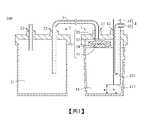
如圖1所示,本發明實施例之氣體捕捉裝置100,其包含:一第一瓶體1、一連接管路3及一氣體稀釋器4。As shown in FIG. 1 , the
第一瓶體1具有一第一容室11及連通第一容室11的一第一進氣口12及一第一出氣口13。第一瓶體1較佳為氣密瓶,例如是台灣專利號I586588的自我壓力密封蓋與瓶身之結合。這樣的氣密瓶可以防止氣體不預期地外洩,且結構輕巧、組裝方便。The first bottle body 1 has a
氣體捕捉裝置100還可以選擇性地包括一第二瓶體2。相似地,第二瓶體2具有一第二容室21及連通第二容室21的一第二進氣口22及一第二出氣口23。第二瓶體2亦較佳為氣密瓶,例如是台灣專利號I586588的自我壓力密封蓋與瓶身之結合。這樣的氣密瓶可以防止氣體不預期地外洩,且結構輕巧、組裝方便。在本實施例中,第二瓶體2用於容置來自第一瓶體1的氣體,故在其他實施例中第二瓶體2為非必要,第二出氣口23也為非必要。在其他實施例中,第二瓶體2可不具有第二出氣口23,而僅具有第二進氣口22。The
連接管路3一端連通第一出氣口13,另一端連通第二瓶體2的第二進氣口22,以使氣體由第一出氣口13進入到第二容室21。One end of the connecting
氣體稀釋器4設置於第一進氣口12。氣體稀釋器4包括一樣品氣體輸送管路42及一保護氣體輸送管路41,保護氣體輸送管路41的末端411位於第一容室11中,樣品氣體輸送管路42的末端421位於保護氣體輸送管路41中,使樣品氣體輸送管路42所輸送的樣品氣體被保護氣體輸送管路41所輸送的保護氣體包覆並稀釋。The
在本實施例中,保護氣體輸送管路41所輸送的保護氣體為氬氣,然而本發明不限於此,保護氣體可以為其他惰性氣體或氮氣等化性不活潑之氣體,或上述氣體之組合。In this embodiment, the shielding gas transported by the shielding
接下來說明本發明的氣體捕捉裝置100如何執行氣體捕捉。Next, how the
第一瓶體1的第一容室11裝有捕捉用溶液,在本實施例中為氫氟酸溶液,實際上捕捉用溶液的成分可以視捕捉需要而改變。The
待捕捉的樣品氣體(以代矽烷樣品為主,為含重金屬的半導體工業用之特殊氣體,然而不限於此)由樣品氣體輸送管路42輸送,同時保護氣體輸送管路41也輸送保護氣體。The sample gas to be captured (mainly the silane sample, which is a special gas used in the semiconductor industry containing heavy metals, but not limited thereto) is delivered by the sample
如圖1所示,樣品氣體輸送管路42的末端421位於保護氣體輸送管路41中,保護氣體輸送管路41的末端411位於第一容室11中且位於捕捉用溶液的水平面下,因此樣品氣體離開樣品氣體輸送管路42的末端421後先被保護氣體所包覆、稀釋,才進入氫氟酸溶液並反應生成反應混合物。樣品氣體中無法與氫氟酸溶液進行反應的成分才離開液面,由第一出氣口13排出並進入第二瓶體2的第二容室21。As shown in Figure 1, the
得到的反應混合物的液體是高基質的溶液,可進一步在受控溫度和壓力條件下減壓蒸發,待至接近乾燥的狀態,所剩餘之物可利用ICP-MS分析其成分。The liquid of the obtained reaction mixture is a high-matrix solution, which can be further evaporated under reduced pressure under controlled temperature and pressure conditions until it is nearly dry, and the remaining substance can be analyzed for its composition by ICP-MS.
綜上所述,本發明的氣體捕捉裝置100利用保護氣體先行包覆、稀釋樣品氣體,才輸送至捕捉用溶液進行反應,使欲捕捉的重金屬或不溶解的奈米顆粒滯留於捕捉用溶液中。本發明的氣體捕捉裝置100相對先前技術更為安全,且瓶體內為對外氣密且高壓,在保障安全的同時更一併確保效率與準確度。To sum up, the
進一步地,在本發明實施例中,如圖1所示,樣品氣體輸送管路42套於保護氣體輸送管路41中,保護氣體輸送管路41的末端411至第一瓶體1的瓶底的距離為a,樣品氣體輸送管路42的末端421至第一瓶體1的瓶底的距離為b,又a大於零且b>a。。如此可使樣品氣體離開樣品氣體輸送管路42時被保護氣體所包覆,且樣品氣體必定先被保護氣體包覆、稀釋才接觸捕捉用溶液。在本發明實施例中,a為1.5公分,b為4公分,然而本發明不限於此,可根據元件的尺寸及配置而相應地調整改變。Further, in the embodiment of the present invention, as shown in FIG. 1 , the sample
進一步地,在本發明實施例中,連接管路3、樣品氣體輸送管路42及保護氣體輸送管路41較佳為鐵氟龍製的硬管,每個管路皆為雙層管,同時兼具化性低與高機械強度的特性,並可防止氣體外洩。Further, in the embodiment of the present invention, the connecting
進一步地,在本發明實施例中,第一瓶體1的體積小於第二瓶體2的體積,較佳為第二瓶體2的體積是第一瓶體1的兩倍以上,以使第一瓶體1的壓力增加時,第二瓶體2仍較能維持常態的壓力,使氣體從第一瓶體1自然流向第二瓶體2。Further, in the embodiment of the present invention, the volume of the first bottle body 1 is smaller than the volume of the second bottle body 2, preferably the volume of the second bottle body 2 is more than twice that of the first bottle body 1, so that the volume of the second bottle body 2 When the pressure of the first bottle body 1 increases, the second bottle body 2 can still relatively maintain the normal pressure, so that the gas flows naturally from the first bottle body 1 to the second bottle body 2 .
進一步地,在本發明實施例中,第一出氣口13的口徑小於第一進氣口12的口徑。其目的是為了使第一容室11的壓力增加,氣體容易進第一容室11但相對難離開第一容室11。讓氣體與液體多次碰撞才能自第一出氣口13逸出,以提高樣品氣體與捕捉用溶液的反應效率。第一進氣口12所插設之管(圖1中為氣體稀釋器4)的管徑例如為1/8”,則第一出氣口13所插設之管的管徑例如為1/16”。Further, in the embodiment of the present invention, the diameter of the
如圖1至圖2B所示,本發明還提出一種隔離膜構件5,設置於第一容室11中。隔離膜構件5包括至少一半透膜層51及一硝酸溶液層52,硝酸溶液層52披覆於半透膜層51。半透膜層51僅允許氣體通過,金屬與大顆的氣膠不會逸出,硝酸溶液層52還可進一步捕捉易揮發的元素,例如汞、鉛及硼等。半透膜層51較佳為四氟乙烯—全氟烷氧基乙烯基醚共聚物(Polyfluoroalkoxy,PFA)半透膜,然而本發明不限於此,亦可以為其他種類的半透膜。硝酸溶液層52為含硝酸之溶液,也可以加入其他種類溶液而形成硝酸基底的混合物,例如王水。As shown in FIG. 1 to FIG. 2B , the present invention also proposes an
本發明提出的隔離膜構件5並不僅限用於氣體捕捉裝置100,也可應用在其他需要防止氣體逃逸的裝置。換句話說,隔離膜構件5可自成一體單獨使用。The
進一步地,在本發明實施例中,隔離膜構件5還可進一步包括二半透膜層51、53及一硝酸溶液層52,硝酸溶液層52設置於二半透膜層51、53之間而上下皆被半透膜層所包覆。二半透膜層51、53與硝酸溶液層52的構造可更防止金屬與大顆的氣膠逃逸,使氣體通過變困難,因而導致第一容室11壓力變大而促進捕捉反應的速率。硝酸溶液層52被夾於二半透膜層51、53之間也可提高操作的安全性。Further, in the embodiment of the present invention, the
進一步地,在本發明實施例中,如圖2A及圖2B所示,隔離膜構件5還包括至少一固定部54,固定部54連接於第一瓶體1的內壁。固定部54的數量可為至少一(環繞半透膜層51)或為二(設置於半透膜層51的兩側),或數量為更多,固定部54的數量與形態可視第一瓶體1做調整。Further, in the embodiment of the present invention, as shown in FIG. 2A and FIG. 2B , the
固定部54還具有一穿孔541,保護氣體輸送管路41貫穿穿孔541而延伸至液面下。The fixing
如圖3所示,本發明還提出另一種氣體稀釋器4a,其形態異於圖1所示的氣體稀釋器4,可直接替換圖1的氣體稀釋器4。As shown in FIG. 3 , the present invention also proposes another
氣體稀釋器4a包含一保護氣體輸送管路41a、一樣品氣體輸送管路42a及一勻氣構件8。The gas diluter 4 a includes a shielding
樣品氣體輸送管路42a的一段為勻氣室421a,勻氣室421a的下游連通一氣體捕捉瓶(即圖1的第一瓶體1)的第一進氣口12。樣品氣體輸送管路樣品氣體輸送管路。A section of the sample
保護氣體輸送管路41a為沿一方向(如圖箭頭所示)輸送保護氣體的管路,保護氣體輸送管路41a的末端411a連通於勻氣室421a,也就是說,樣品氣體輸送管路42a所輸送的樣品氣體在勻氣室421a中與保護氣體輸送管路41a輸送的保護氣體相混合。The shielding
勻氣構件8設置於勻氣室421a中,勻氣構件8可為具有葉片的風扇,可為有動力地主動旋轉加速樣品氣體與保護氣體的混合,也可以是無動力式的,利用保護氣體輸送管路41a穩定地輸送保護氣體作為動力而旋轉。然而本發明不限於此,勻氣構件8可以為其他適於幫助樣品氣體與保護氣體混合的構件。The
藉由本發明的氣體稀釋器4a,利用充分混合的保護氣體先行包覆、稀釋樣品氣體,才輸送至捕捉用溶液進行反應,使欲捕捉的重金屬或不溶解的奈米顆粒滯留於捕捉用溶液中。相對先前技術,利用本發明的氣體稀釋器4a更為安全,在保障安全的同時一並確保效率與準確度。With the
進一步地,在本發明實施例中,勻氣室421a的截面積大於樣品氣體輸送管路42a的其他段,使得勻氣室421a有足夠的空間與時間讓樣品氣體與保護氣體混合、稀釋。Further, in the embodiment of the present invention, the cross-sectional area of the
進一步地,在本發明實施例中,保護氣體輸送管路41a的截面積大於樣品氣體輸送管路42a進入勻氣室421a之前的段的截面積,使樣品氣體可以以高壓、少量的方式進入勻氣室421a中,而確實地被保護氣體混合、包覆。較小的截面積也有利於精準控制樣品氣體進入勻氣室421a的總量。Further, in the embodiment of the present invention, the cross-sectional area of the shielding
進一步地,在本發明實施例中,氣體稀釋器4a更包括一外管61及一恆溫構件62,外管61包覆勻氣室421a,恆溫構件62位於外管61及勻氣室421a之間。恆溫構件62用以對勻氣室421a加熱,以增加氣體分子的運動速率及擴散效率。在本實施例中,如圖3所示,恆溫構件62為環形電熱件,然而本發明不限於此,在其他實施例中,恆溫構件62為填充於外管61及勻氣室421a之間的熱液層。熱液層(例如是熱水)經加熱後流入外管61中,以保持勻氣室421a內恆定的溫度。Further, in the embodiment of the present invention, the
進一步地,在本發明實施例中,氣體稀釋器4a更包括一保溫管63,保溫管63包覆外管61。保護氣體輸送管路41a及樣品氣體輸送管路42a較佳為鐵氟龍製的硬管,每個管路皆為雙層管,兼具化性低與高機械強度的特性,並可防止氣體外洩。外管61亦為鐵氟龍管,保溫管63則為聚丙烯管,用以保溫隔熱。然而本發明不限於此,在其他實施例中,保溫管63可為其他隔熱材質所製成。Further, in the embodiment of the present invention, the
進一步地,在本發明實施例中,氣體稀釋器4a更包括一取樣構件7。取樣構件7包括一控制單元71、一對控制閥72及一連通樣品氣體輸送管路42a的U形管73。Further, in the embodiment of the present invention, the
控制閥72包括上游控制閥721及下游控制閥722,分別設置於U形管73的上下游兩端。U形管73的上游連通樣品氣體源,U形管73的下游連通樣品氣體輸送管路42a。上游控制閥721及下游控制閥722用以控制樣品氣體的輸入。The
控制單元71分別訊號連接上游控制閥721及下游控制閥722。控制單元71可控制上游控制閥721及下游控制閥722的開啟、關閉,而決定是否輸送樣品氣體至勻氣室421a、以及輸送多少量。控制單元71例如是控制晶片或控制電路。The
進一步地,在本發明實施例中,取樣構件7更包括一液面高度偵測單元76及一溫度控制單元75。液面高度偵測單元76及溫度控制單元75分別訊號連接控制單元71,U形管73的底部設置於溫度控制單元75中。溫度控制單元75提供冷浴,以乾冰或其他冷液冷浴U形管73的底部。控制單元71控制上游控制閥721開啟,使樣品氣體輸入至U形管73,樣品氣體在U形管73的底部被冷凝成液體。液面高度偵測單元76偵測液態狀的樣品氣體在U形管73中的高度,並至達到一預設的高度後,控制單元71控制上游控制閥721關閉,並接著控制下游控制閥722開啟、溫度控制單元75升溫使液態狀的樣品氣體全部蒸發回氣態,而輸送至樣品氣體輸送管路42a及勻氣室421a。藉此,可精準地控制樣品氣體進入樣品氣體輸送管路42a的總量。液面高度偵測單元76可以例如是應用光學原理的偵測單元,偵測預設的高度的光學折射/反射變化;也可以是應用浮力原理的偵測單元,當液面升高至預設的高度後使浮球觸發/被觸發,且本發明不限於此,任何一般技術手段的液面高度偵測單元76都可應用於本發明的氣體稀釋器4a。Further, in the embodiment of the present invention, the
進一步地,在本發明另一實施例中,取樣構件7更包括一測重單元74。測重單元74訊號連接控制單元71。與前一個實施例的差別在於,不以U形管73的液面高度計算樣品氣體的總量,而改以重量變化精準計算樣品氣體的輸出量。Furthermore, in another embodiment of the present invention, the sampling
詳細來說,溫度控制單元75提供冷浴,以乾冰或其他冷液冷浴U形管73的底部。控制單元71控制上游控制閥721開啟,使樣品氣體輸入至U形管73,樣品氣體在U形管73的底部被冷凝。而接著控制單元71控制上游控制閥721關閉,並控制下游控制閥722開啟,溫度控制單元75升溫而使樣品氣體蒸發,進入樣品氣體輸送管路42a及勻氣室421a。In detail, the
測重單元74較佳地設置於U形管73的底部,用於量測U形管73重量變化。因此控制單元71藉由測重單元74,可精確地計算有多少樣品氣體進入U形管73並冷凝,以及有多少樣品氣體離開U形管73,從而精確地控制輸入至勻氣室421a的樣品氣體的質量。The weighing
本發明在上文中已以實施例揭露,然熟習本項技術者應理解的是,該實施例僅用於描繪本發明,而不應解讀為限制本發明之範圍。應注意的是,舉凡與該實施例等效之變化與置換,均應設為涵蓋於本發明之範疇內。因此,本發明之保護範圍當以申請專利範圍所界定者為準。The present invention has been disclosed by the embodiments above, but those skilled in the art should understand that the embodiments are only for describing the present invention, and should not be construed as limiting the scope of the present invention. It should be noted that all changes and substitutions equivalent to the embodiment should be included in the scope of the present invention. Therefore, the scope of protection of the present invention should be defined by the scope of the patent application.
100:氣體捕捉裝置 1:第一瓶體 11:第一容室 12:第一進氣口 13:第一出氣口 2:第二瓶體 21:第二容室 22:第二進氣口 23:第二出氣口 3:連接管路 4:氣體稀釋器 41:保護氣體輸送管路 411:保護氣體輸送管路的末端 411a:保護氣體輸送管路的末端 41a:保護氣體輸送管路 42:樣品氣體輸送管路 421:樣品氣體輸送管路的末端 421a:勻氣室 42a:樣品氣體輸送管路 4a:氣體稀釋器 5:隔離膜構件 51:半透膜層 52:硝酸溶液層 53:半透膜層 54:固定部 541:穿孔 61:外管 62:恆溫構件 63:保溫管 64:清潔氣體輸送管路 7:取樣構件 71:控制單元 72:控制閥 721:上游控制閥 722:下游控制閥 73:U形管 74:測重單元 75:溫度控制單元 76:液面高度偵測單元 8:勻氣構件 a:距離 b:距離100: gas capture device 1: The first bottle 11: The first chamber 12: The first air inlet 13: The first air outlet 2: The second bottle 21: The second chamber 22: Second air inlet 23: Second air outlet 3: Connect the pipeline 4: Gas diluter 41: Protective gas delivery pipeline 411: The end of the shielding
圖1係為根據本發明實施例之氣體捕捉裝置之示意圖。 圖2A係為根據本發明實施例之隔離膜構件之立體示意圖。 圖2B係為根據本發明實施例之隔離膜構件之組裝示意圖。 圖3係為根據本發明另一實施例之氣體稀釋器之示意圖。FIG. 1 is a schematic diagram of a gas capture device according to an embodiment of the present invention. FIG. 2A is a schematic perspective view of an isolation membrane member according to an embodiment of the present invention. FIG. 2B is a schematic diagram of the assembly of the isolation membrane member according to the embodiment of the present invention. Fig. 3 is a schematic diagram of a gas diluter according to another embodiment of the present invention.
100:氣體捕捉裝置100: gas capture device
1:第一瓶體1: The first bottle
11:第一容室11: The first chamber
12:第一進氣口12: The first air inlet
13:第一出氣口13: The first air outlet
2:第二瓶體2: The second bottle
21:第二容室21: The second chamber
22:第二進氣口22: Second air inlet
23:第二出氣口23: Second air outlet
3:連接管路3: Connect the pipeline
4:氣體稀釋器4: Gas diluter
41:保護氣體輸送管路41: Protective gas delivery pipeline
411:保護氣體輸送管路的末端411: The end of the shielding gas delivery line
42:樣品氣體輸送管路42: Sample gas delivery pipeline
421:樣品氣體輸送管路的末端421: End of sample gas delivery line
5:隔離膜構件5: Isolation membrane member
51:半透膜層51: Semi-permeable membrane layer
52:硝酸溶液層52: nitric acid solution layer
53:半透膜層53: semi-permeable membrane layer
54:固定部54: fixed part
a:距離a: distance
b:距離b: distance
Claims (10)
Translated fromChinesePriority Applications (2)
| Application Number | Priority Date | Filing Date | Title |
|---|---|---|---|
| TW110144389ATWI780996B (en) | 2021-11-29 | 2021-11-29 | gas capture device |
| CN202111603781.XACN116173864A (en) | 2021-11-29 | 2021-12-24 | Gas capturing device |
Applications Claiming Priority (1)
| Application Number | Priority Date | Filing Date | Title |
|---|---|---|---|
| TW110144389ATWI780996B (en) | 2021-11-29 | 2021-11-29 | gas capture device |
Publications (2)
| Publication Number | Publication Date |
|---|---|
| TWI780996Btrue TWI780996B (en) | 2022-10-11 |
| TW202321669A TW202321669A (en) | 2023-06-01 |
Family
ID=85475986
Family Applications (1)
| Application Number | Title | Priority Date | Filing Date |
|---|---|---|---|
| TW110144389ATWI780996B (en) | 2021-11-29 | 2021-11-29 | gas capture device |
Country Status (2)
| Country | Link |
|---|---|
| CN (1) | CN116173864A (en) |
| TW (1) | TWI780996B (en) |
Families Citing this family (1)
| Publication number | Priority date | Publication date | Assignee | Title |
|---|---|---|---|---|
| TWI792725B (en)* | 2021-11-29 | 2023-02-11 | 樂盟科技有限公司 | Gas diluter and gas capture device with gas diluter |
Citations (2)
| Publication number | Priority date | Publication date | Assignee | Title |
|---|---|---|---|---|
| CN1614385A (en)* | 2004-12-03 | 2005-05-11 | 北京大学 | Contour tracking fixed source diluting sampling system |
| CN1681937A (en)* | 2002-07-20 | 2005-10-12 | 美国艾森生物科学公司 | Apparatuses and method based impedance for analyzing cells and granules |
Family Cites Families (7)
| Publication number | Priority date | Publication date | Assignee | Title |
|---|---|---|---|---|
| RU2056148C1 (en)* | 1992-01-30 | 1996-03-20 | Игорь Николаевич Бекман | Gas mixture membrane separation apparatus |
| JP2003028765A (en)* | 2001-07-18 | 2003-01-29 | Horiba Ltd | Analytical device and method of particulate matter in engine exhaust gas |
| CN102363093A (en)* | 2011-06-23 | 2012-02-29 | 西安康本材料有限公司 | Processing apparatus of exhaust gas discharged during a PAN protofilament carbonization process |
| CN203564978U (en)* | 2013-11-25 | 2014-04-30 | 长沙有色冶金设计研究院有限公司 | Liquid ammonia diluter |
| CN107167418B (en)* | 2017-05-24 | 2020-05-01 | 南京博沃科技发展有限公司 | Boiler water wall high-temperature corrosion on-line monitoring method and monitoring system |
| TWI672488B (en)* | 2018-10-12 | 2019-09-21 | 國立交通大學 | Gas collection device and apparatus for gas collection and analysis |
| TWI804074B (en)* | 2021-11-29 | 2023-06-01 | 樂盟科技有限公司 | Isolation membrane member and gas capture device having the isolation membrane member |
- 2021
- 2021-11-29TWTW110144389Apatent/TWI780996B/enactive
- 2021-12-24CNCN202111603781.XApatent/CN116173864A/enactivePending
Patent Citations (2)
| Publication number | Priority date | Publication date | Assignee | Title |
|---|---|---|---|---|
| CN1681937A (en)* | 2002-07-20 | 2005-10-12 | 美国艾森生物科学公司 | Apparatuses and method based impedance for analyzing cells and granules |
| CN1614385A (en)* | 2004-12-03 | 2005-05-11 | 北京大学 | Contour tracking fixed source diluting sampling system |
Also Published As
| Publication number | Publication date |
|---|---|
| CN116173864A (en) | 2023-05-30 |
| TW202321669A (en) | 2023-06-01 |
Similar Documents
| Publication | Publication Date | Title |
|---|---|---|
| TWI780996B (en) | gas capture device | |
| TWI792725B (en) | Gas diluter and gas capture device with gas diluter | |
| TWI804074B (en) | Isolation membrane member and gas capture device having the isolation membrane member | |
| US20160123946A1 (en) | System for analyzing mercury | |
| JP7650942B2 (en) | Multi-sensor gas sampling detection system for radical gases and short-lived molecules and method of use - Patents.com | |
| WO2016011447A1 (en) | Aerosol particle growth systems using polymer electrolyte membranes | |
| CN106872372B (en) | A constant-temperature integrating sphere device for gas analysis | |
| CN101443659A (en) | Three-wafer channel structure for a fluid analyzer | |
| CN112169668A (en) | A dynamic volume saturated gas generator and generation system based on condensation saturation | |
| CN103901142B (en) | A kind of water that to be separated in alcoholic beverage is for the method for H and O isotope assay | |
| CN211636047U (en) | Device for producing low-concentration standard gas mixture | |
| CN111013415A (en) | Standard gas generation system based on temperature control | |
| CN104662422B (en) | Gas balance coil for providing gas calibration solution in real time | |
| JP2018004400A (en) | Gas concentration measurement device | |
| CN116698811A (en) | HO 2 Method and device for realizing interference-free measurement of heterogeneous uptake coefficient of free radical | |
| Zheng et al. | Study of the influence of surfactants and surface treatments on the minimum wetting rate of falling films of aqueous LiBr and Carrol solutions | |
| JP6843988B2 (en) | Condensed water discharge system for exhaust measurement equipment | |
| JP5630894B2 (en) | Particulate matter measuring device | |
| Zhao et al. | Measurements of multicomponent microdroplet evaporation by using Rainbow Refractometer and PDA | |
| CN213726206U (en) | Dynamic volume saturated gas generator based on condensation saturation | |
| Guan et al. | The Effects of the Structural Tuning on the Sensing Performance of Extinguishant Detector Based on the Differential Pressure Principle | |
| TWI851285B (en) | Gas mixing device and treatment equipment for oxidation process | |
| Ku et al. | An online parallel-plate wet denuder system for monitoring acetic acid gas | |
| CN111569688A (en) | A wide-range standard poisonous gas generator and its quantitative method | |
| CN220603366U (en) | A fluoride ion measuring instrument for controlling the volume of condensed distillate |
Legal Events
| Date | Code | Title | Description |
|---|---|---|---|
| GD4A | Issue of patent certificate for granted invention patent |