TWI777708B - Toilet floor cleaning device - Google Patents
Toilet floor cleaning deviceDownload PDFInfo
- Publication number
- TWI777708B TWI777708BTW110128114ATW110128114ATWI777708BTW I777708 BTWI777708 BTW I777708BTW 110128114 ATW110128114 ATW 110128114ATW 110128114 ATW110128114 ATW 110128114ATW I777708 BTWI777708 BTW I777708B
- Authority
- TW
- Taiwan
- Prior art keywords
- cleaning
- outer casing
- reciprocating driving
- cleaning device
- urinal
- Prior art date
Links
- 238000004140cleaningMethods0.000titleclaimsabstractdescription92
- XLYOFNOQVPJJNP-UHFFFAOYSA-NwaterSubstancesOXLYOFNOQVPJJNP-UHFFFAOYSA-N0.000claimsdescription40
- 230000007246mechanismEffects0.000claimsdescription5
- 230000006698inductionEffects0.000claimsdescription4
- 238000003825pressingMethods0.000claimsdescription4
- 230000008447perceptionEffects0.000abstractdescription3
- 238000010586diagramMethods0.000description11
- 230000000694effectsEffects0.000description8
- 230000003749cleanlinessEffects0.000description7
- 230000018044dehydrationEffects0.000description7
- 238000006297dehydration reactionMethods0.000description7
- 230000006870functionEffects0.000description5
- 238000005406washingMethods0.000description5
- 230000009471actionEffects0.000description4
- 238000007605air dryingMethods0.000description3
- 238000000034methodMethods0.000description3
- 210000002700urineAnatomy0.000description3
- 238000010521absorption reactionMethods0.000description2
- 238000013459approachMethods0.000description2
- 230000007812deficiencyEffects0.000description2
- 238000013461designMethods0.000description2
- 230000005611electricityEffects0.000description2
- 230000008676importEffects0.000description2
- 238000004519manufacturing processMethods0.000description2
- 238000012986modificationMethods0.000description2
- 230000004048modificationEffects0.000description2
- 230000008569processEffects0.000description2
- 238000012552reviewMethods0.000description2
- 239000010865sewageSubstances0.000description2
- 229920000742CottonPolymers0.000description1
- 206010028813NauseaDiseases0.000description1
- 230000000903blocking effectEffects0.000description1
- 239000012141concentrateSubstances0.000description1
- 238000011109contaminationMethods0.000description1
- 230000007423decreaseEffects0.000description1
- 239000004744fabricSubstances0.000description1
- 238000011010flushing procedureMethods0.000description1
- 230000005484gravityEffects0.000description1
- 230000006872improvementEffects0.000description1
- 238000012423maintenanceMethods0.000description1
- 239000000463materialSubstances0.000description1
- 230000027939micturitionEffects0.000description1
- 230000008693nauseaEffects0.000description1
- 238000005096rolling processMethods0.000description1
- 239000007921spraySubstances0.000description1
Images


Landscapes
- Sanitary Device For Flush Toilet (AREA)
- Cleaning In General (AREA)
Abstract
Translated fromChineseDescription
Translated fromChinese本發明為提供一種廁所地板之清潔裝置,尤指一種可自動對小便斗下方之地板進行清潔,以在不影響使用者習慣的情況下,達到維持整體環境整潔、提升使用觀感、減少清潔人力功效的廁所地板之清潔裝置。The present invention is to provide a toilet floor cleaning device, especially a device that can automatically clean the floor below the urinal, so as to maintain the overall cleanliness of the environment, improve the appearance of use, and reduce cleaning manpower without affecting the user's habits. toilet floor cleaning device.
按,小便斗是一種設置於牆壁上的小便設施,常見於男廁內,供男性小便使用,且目前小便斗幾乎都使用紅外線自動感應清潔,於感應到人員靠近時先行噴水清潔,並於人員離開時再次噴水清潔,以避免尿漬殘留於小便斗內,然而,此種自動清潔裝置僅針對小便斗內,並未針對地板,而小便斗下方的地板是否乾淨,也會直接影響使用者使用的意願,且地上的尿漬若未及時處理,更會造成環境惡臭。Press, urinal is a kind of urination facility installed on the wall. It is commonly used in men's toilets for men to urinate. At present, almost all urinals use infrared automatic induction cleaning. Spray water again when leaving to avoid urine stains remaining in the urinal. However, this automatic cleaning device is only aimed at the inside of the urinal, not the floor. Whether the floor under the urinal is clean will also directly affect the use of the urinal. If the urine stains on the ground are not dealt with in time, it will cause the environment to stink.
目前對於廁所地板清潔的維持,絕大多數還是採用警語標示及人力清潔,其中警語的功效不言而喻,至於人力清潔的方式在使用頻率較低的場域尚可接受,但在人潮較多的場域(如車站),很難確實維持整潔,若縮短打掃時間間隔,不但會增加人力成本,廁所也會經常處於地板濕滑狀態,而徒增場域危險性。At present, for the maintenance of toilet floor cleaning, the vast majority still use warning signs and manual cleaning. The efficacy of warning words is self-evident. As for the manual cleaning method, it is acceptable in the field of low frequency, but in crowded areas. In many areas (such as stations), it is difficult to maintain cleanliness. If the cleaning interval is shortened, not only will the labor cost be increased, but the toilet will often be in a state of slippery floors, which will increase the danger of the area.
另有在小便斗下方設置腳踏板之解決方式,此種腳踏板通常會搭配水洗系統、甚至風乾系統,但增設腳踏板會影響使用者的使用習慣,即使經過水洗及風乾,也很難抹滅使用者對腳踏板的清潔疑慮,畢竟使用者對腳踏板乾淨程度的判斷始終不如對地板表面來的直觀,再者,風乾系統與擺放電風扇之效果雷同,其效果無法立竿見影,而地板或腳踏板在水洗後一直到完全乾燥前,有很大的機率會有下一名使用者接續使用。Another solution is to set a foot pedal under the urinal. This kind of foot pedal is usually equipped with a washing system or even an air-drying system. However, adding a foot pedal will affect the user's usage habits. Even after washing and air-drying, it is very It is difficult to erase the user's doubts about the cleanliness of the pedals. After all, the user's judgment of the cleanliness of the pedals is not as intuitive as the floor surface. Furthermore, the effect of the air-drying system is similar to that of placing an electric fan, and its effect cannot be Immediate results, while the floor or pedals have a high chance of being used by the next user after washing until they are completely dry.
是以,要如何解決上述習用之問題與缺失,以在第一時間維持小便斗下方地板的「乾」與「淨」,即為本發明之發明人與從事此行業之相關廠商所亟欲研究改善之方向所在者。Therefore, how to solve the above-mentioned conventional problems and deficiencies, so as to maintain the "dry" and "clean" floor under the urinal at the first time, is the inventor of the present invention and the relevant manufacturers engaged in this industryThe direction of improvement that is urgently needed to be studied.
故,本發明之發明人有鑑於上述缺失,乃蒐集相關資料,經由多方評估及考量,並以從事於此行業累積之多年經驗,經由不斷試作及修改,始設計出此種可自動對小便斗下方之地板進行清潔,以在不影響使用者習慣的情況下,達到維持整體環境整潔、提升使用觀感、減少清潔人力功效的廁所地板之清潔裝置的發明專利者。Therefore, in view of the above deficiencies, the inventor of the present invention collected relevant information, evaluated and considered from various parties, and based on years of experience accumulated in this industry, through continuous trial production and modification, to design this kind of automatic urinal. The floor below is cleaned, so as to maintain the overall cleanliness of the environment, improve the user's appearance, and reduce the efficiency of cleaning the toilet floor, without affecting the user's habits. The patentee of the invention.
本發明之主要目的在於:配合感應元件,在使用完小便斗後,啟動往復驅動裝置使其自動擦拭地板,藉此在小便斗每次使用後,皆可第一時間維持小便斗下方地板的「乾」與「淨」。The main purpose of the present invention is to cooperate with the sensing element to activate the reciprocating drive device to automatically wipe the floor after the urinal is used, so that the floor under the urinal can be maintained for the first time after each use of the urinal. dry" and "clean".
本發明之另一主要目的在於:利用低科技簡單完成小便斗下方的地板清潔,以提升使用觀感、減少清潔人力。Another main purpose of the present invention is to simply complete the floor cleaning under the urinal with low technology, so as to improve the appearance of use and reduce cleaning manpower.
為達成上述目的,本發明之清潔裝置係設置於一小便斗下方,該清潔裝置主要包括:一外殼體、一進出口、一往復驅動裝置、一滾筒件、一清潔件、一感應元件、及一供電元件,其中該外殼體係設於地板及小便斗所在之牆面一側,該進出口係形成於外殼體背離牆面之一側,該往復驅動裝置係設於外殼體內,該滾筒件係設於往復驅動裝置上,以經由進出口移動至外殼體外,該清潔件係設置於滾筒件表面,以供擦拭地板,該感應元件係電性連結往復驅動裝置並供感應使用者之位置,以於使用者離開時啟動往復驅動裝置,而該供電元件設於外殼體上且電性連結往復驅動裝置。In order to achieve the above object, the cleaning device of the present invention is arranged below a urinal, and the cleaning device mainly includes: an outer casing, an inlet and outlet, a reciprocating driving device, a roller element, a cleaning element, a sensing element, and A power supply element, wherein the shell system is arranged on the side of the wall where the floor and the urinal are located, the inlet and outlet are formed on the side of the outer shell facing away from the wall, the reciprocating driving device is arranged in the outer shell, the roller is It is arranged on the reciprocating drive device to move to the outside of the housing through the inlet and outlet. The cleaning element is arranged on the surface of the roller for wiping the floor. The sensing element is electrically connected to the reciprocating drive device and is used to sense the user's position to sense the position of the user. The reciprocating driving device is activated when the user leaves, and the power supply element is arranged on the outer casing and is electrically connected to the reciprocating driving device.
當使用者靠近小便斗時,會正常的啟動小便斗的自動清洗功能,而在使用者離開時,不但會再次啟動該自動清洗功能,也會利用感應元件同時啟動往復驅動裝置,使滾筒件由進出口移動至外殼體外,以利用清潔件快速擦拭地板,藉此,在第一時間快速完成小便斗下方地板的清潔,確實維持地板在乾淨狀態,避免造成使用時的噁心感,進而減少清潔人力。When the user approaches the urinal, the automatic cleaning function of the urinal will be activated normally, and when the user leaves, not only will the automatic cleaning function be activated again, but also the reciprocating driving device will be activated at the same time by using the sensing element, so that the roller is moved from The inlet and outlet are moved to the outside of the casing to quickly wipe the floor with the cleaning element, thereby quickly completing the cleaning of the floor under the urinal at the first time, keeping the floor in a clean state, avoiding nausea during use, and reducing cleaning manpower .
藉由上述技術,可針對習用廁所地板之清潔所存在之仍仰賴人力清潔、無法經常保持乾燥、及腳踏板會影響使用習慣等問題點加以突破,達到上述優點之實用進步性。With the above technology, the cleaning of the conventional toilet floor can be solved by manpower, unable to keep dry frequently, and the foot pedal will affect the usage habits, etc., and achieve the practical progress of the above advantages.
1、1a、1b、1c:外殼體1, 1a, 1b, 1c: outer casing
11、11b、11c:進出口11, 11b, 11c: Import and export
12a、12b、12c:導水部12a, 12b, 12c: water guide
121a、121b、121c:排水部121a, 121b, 121c: Drainage part
13b:遮蔽件13b: Shield
2、2a、2d:往復驅動裝置2, 2a, 2d: Reciprocating drive device
21、21d:往復驅動部21, 21d: Reciprocating drive part
211:擺動件211: Swing pieces
212d:伸縮件212d: Telescopic parts
22a、22b:旋轉驅動部22a, 22b: Rotary drive part
3、3a、3b、3c、3d:滾筒件3, 3a, 3b, 3c, 3d: roller parts
31、31a、31b、31c、31d:清潔件31, 31a, 31b, 31c, 31d: Cleaning parts
4、4b:感應元件4, 4b: Sensing element
5、5b:供電元件5, 5b: power supply components
6a、6b、6c:自潔組件6a, 6b, 6c: Self-cleaning components
61a、61b:進水部61a, 61b: water inlet
62a、62b:出水部62a, 62b: water outlet
7c:脫水機構7c: Dehydration mechanism
71c:緊迫部71c: Ministry of Emergencies
8、8a、8b:小便斗8, 8a, 8b: Urinals
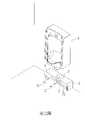
第一圖 係為本發明第一較佳實施例之立體透視圖。The first figure is a perspective perspective view of the first preferred embodiment of the present invention.
第二圖 係為本發明第一較佳實施例之使用狀態圖。The second figure is a use state diagram of the first preferred embodiment of the present invention.
第三圖 係為本發明第一較佳實施例之感應示意圖。The third figure is a schematic diagram of the induction of the first preferred embodiment of the present invention.
第四圖 係為本發明第一較佳實施例之清潔示意圖。Figure 4 is a schematic diagram of cleaning according to the first preferred embodiment of the present invention.
第五圖 係為本發明第二較佳實施例之立體透視圖。Figure 5 is a perspective perspective view of the second preferred embodiment of the present invention.
第六圖 係為本發明第二較佳實施例之自潔示意圖。The sixth figure is a schematic diagram of the self-cleaning of the second preferred embodiment of the present invention.
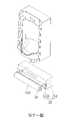
第七圖 係為本發明第三較佳實施例之立體透視圖。Fig. 7 is a perspective perspective view of the third preferred embodiment of the present invention.
第八圖 係為本發明第三較佳實施例之自潔示意圖。Figure 8 is a schematic diagram of the self-cleaning of the third preferred embodiment of the present invention.
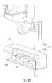
第九圖 係為本發明第三較佳實施例之脫水示意圖。Figure 9 is a schematic diagram of dehydration in the third preferred embodiment of the present invention.
第十圖 係為本發明第四較佳實施例之脫水示意圖。Figure 10 is a schematic diagram of the dehydration of the fourth preferred embodiment of the present invention.
第十一圖 係為本發明第五較佳實施例之立體透視圖。Figure 11 is a perspective perspective view of the fifth preferred embodiment of the present invention.
為達成上述目的及功效,本發明所採用之技術手段及構造,茲繪圖就本發明較佳實施例詳加說明其特徵與功能如下,俾利完全了解。In order to achieve the above objects and effects, the technical means and structures adopted by the present invention are described in detail with reference to the preferred embodiments of the present invention, and the features and functions are as follows, so as to be fully understood.
請參閱第一圖及第二圖所示,係為本發明第一較佳實施例之立體透視圖及使用狀態圖,由圖中可清楚看出本發明之清潔裝置係設置於一小便斗8下方,該清潔裝置主要包括:Please refer to the first and second figures, which are three-dimensional perspective views and use state views of the first preferred embodiment of the present invention. It can be clearly seen from the figures that the cleaning device of the present invention is arranged in a
一外殼體1,係設於地板及該小便斗8所在之牆面一側;An
一進出口11,係形成於該外殼體1背離該牆面之一側;An inlet and
一往復驅動裝置2,係設於該外殼體1內,該往復驅動裝置2具有一往復驅動部21、及一設於該往復驅動部21上之擺動件211,本實施例中該往復驅動部21係為擺動馬達,擺動件211為受擺動馬達連動之桿體,但不以此為限;A
一滾筒件3,係設於該往復驅動裝置2之擺動件211上,以經由該進出口11移動至該外殼體1外;A
一清潔件31,係設置於該滾筒件3表面,以供擦拭該地板;A cleaning
一感應元件4,係與該外殼體1結合且電性連結該往復驅動裝置2,並供感應使用者之位置,以於使用者離開時啟動該往復驅動裝置2;及A
一供電元件5,係設於該外殼體1上且電性連結該往復驅動裝置2,本實施例之供電元件5係以電池作為舉例,但不以此為限。A
藉由上述之說明,已可了解本技術之結構,而依據這個結構之對應配合,更可自動對小便斗8下方之地板進行清潔,以在不影響使用者習慣的情況下,達到維持整體環境整潔、提升使用觀感、減少清潔人力功效等優勢,而詳細之解說將於下述說明。From the above description, the structure of the present technology can be understood, and according to the corresponding cooperation of this structure, the floor below the
請同時配合參閱第一圖至第四圖所示,係為本發明第一較佳實施例之立體透視圖至清潔示意圖,藉由上述構件組構時,由第二圖中可清楚看出,由於小便斗8的使用已然普及化,故本發明利用內建供電元件5的方式,將外殼體1直接設置於小便斗8下方,即可正常使用,無須改動既有小便斗8的任何設計,且就整體外觀而言,只是在每個小便斗8下的牆角處多一個外殼體1,外殼體1的寬度與小便斗8相仿,而使用者同樣直接站在廁所的地板上,基本上外殼體1的深度不影響使用時的站位,也不會影響使用者習慣,而有利於廁所環境整潔之推廣。Please also refer to the first figure to the fourth figure, which are the three-dimensional perspective view to the cleaning schematic diagram of the first preferred embodiment of the present invention. When the above components are assembled, it can be clearly seen from the second figure, Since the use of the
實際使用時,當使用者靠近小便斗8時,小便斗8的紅外線感測器會正常的啟動小便斗8的自動清洗功能,而在使用者離開時,不但會再次啟動該自動清洗功能,也會利用外殼體1上的感應元件4同時啟動往復驅動裝置2的往復驅動部21,使滾筒件3利用擺動件211從進出口11移動至外殼體1外,以利用清潔件31快速擦拭地板。其中,滾筒件3的擺幅可為90度或180度,擺幅90度時往復驅動部21設於外殼體1側處、擺幅180度時往復驅動部21設於外殼體1中央處,而所謂往復驅動意指其擺動路徑為向外擺動至定點後會再由原路徑反向移動至外殼體1內,故本實施例係以180度作為舉例,更可避免清潔件31上的髒汙,因為折返動作而殘留在外。至於清潔件31可為棉質布料、吸水海綿等,為可拆卸的設置於滾筒件3上之設計,因小便斗8下方的尿漬量很小,配合滾筒件3的滾動效果,清潔件31的吸水位置可均勻分布,基本上清潔件31可支撐的時間已足夠,清潔人員只要在打掃時做清潔或替換的動作即可。In actual use, when the user approaches the
再請同時配合參閱第五圖及第六圖所示,係為本發明第二較佳實施例之立體透視圖及自潔示意圖,由圖中可清楚看出,本實施例與上述實施例為大同小異,僅於該往復驅動裝置2a具有一旋轉驅動部22a,且該滾筒件3a係連結於該旋轉驅動部22a上,以使該滾筒件3a自體旋轉,且該外殼體1a具有一設於該滾筒件3a下方之導水部12a、及一設於該導水部12a一端之排水部121a,並本實施例之清潔裝置另具有一自潔組件6a,該自潔組件6a包含有一連結水源之進水部61a、及一設於該外殼體1a上且位於該滾筒件3a一側之出水部62a。另外,本實施例之滾筒件3a擺幅係以90度作為舉例,縮小為90度的擺幅得以較小的外殼體1a體積,清潔較大的範圍,進一步降低外殼體1a對使用者站位的負面觀感影響。Please also refer to Figure 5 and Figure 6, which are three-dimensional perspective views and self-cleaning schematic diagrams of the second preferred embodiment of the present invention.For the sake of similarities, only the
其中,旋轉驅動部22a為中高轉速之馬達,使該滾筒件3a向外移動時,可利用旋轉驅動部22a的主動旋轉,讓清潔件31a的吸水位置分布更均勻、吸水效果更佳。自潔組件6a為一種水洗系統,用來水洗清潔件31a,以延長清潔件31a的使用時間,本實施例之進水部61a為獨立連結水源之水管,出水部62a為噴水口,用以在滾筒件3a回收至外殼體1a內時,對清潔件31a進行沖洗動作,清洗時可配合旋轉驅動部22a讓滾筒件3a進行自轉,以提高沖洗效果,且本實施例中,外殼體1a的底面具有微凸起態樣的導水部12a,藉此在沖洗過程中,利用導水部12a形成的斜面避免汙水流向外殼體1a外,而排水部121a則為導水部12a最低點的排水口,排水部121a可連通相鄰小便斗8a的其他排水部121a,進而共同流向地板排水孔。Wherein, the
又請同時配合參閱第七圖至第九圖所示,係為本發明第三較佳實施例之立體透視圖至脫水示意圖,考慮到新建廁所的小便斗8b使用本發明之可能,感應元件4b可直接與小便斗8b的紅外線感應器共用,以降低本發明之材料成本,且供電元件5b、自潔組件6b的進水部61b、及排水部121b也可直接與小便斗8b的水電管線作連結,如此一來,也可將所有水電管線全部埋藏在壁面,而提升外在美觀。Please also refer to Figures 7 to 9, which are three-dimensional perspective views to dehydration schematic diagrams of the third preferred embodiment of the present invention. Considering the possibility of using the present invention for the
另外,該外殼體1b於該進出口11b端處可樞設有一遮蔽件13b,該遮蔽件13b作為活動門片使用,利用其重力自然垂置於進出口11b處,而受滾筒件3b抵觸時,不論其移動方向為向內或向外,遮蔽件13b皆可順勢開啟,以於非動作狀態下遮蔽外殼體1b內部,也可利用遮蔽件13b的擋水效果,在滾筒件3b收容於外殼體1b內時、自潔組件6b清潔過後,啟動旋轉驅動部22b令其高速旋轉,藉此利用高速旋轉產生的離心力進行脫水,飛濺出來的水滴不但會受遮蔽件13b阻擋,也會經由導水部12b流向排水部121b,如此一來,自潔組件6b即使使用較大量的水進行沖洗(出水部62b數量為複數個),也可利用旋轉驅動部22b快速脫水,進而保持清潔件31b的清潔力。In addition, a shielding
另請同時配合參閱第十圖所示,係為本發明第四較佳實施例之脫水示意圖,由圖中可清楚看出,本實施例與上述實施例為大同小異,僅令該自潔組件6c具有一作用於該清潔件31c之脫水機構7c,且該脫水機構7c具有一設於該外殼體1c內之緊迫部71c,係使該外殼體1c內之空間高度由該進出口11c一側向牆面一側呈漸縮態樣,其中緊迫部71c為設置於外殼體1c內的傾斜結構,以藉由外而內逐漸變小的空間高度,讓滾筒件3c進入外殼體1c內部時,受到緊迫部71c的擠壓而將清潔件31c吸收的水分排出,過程中同樣利用導水部12c將汙水集中至排水部121c處,如此一來,即可利用簡單的非動力結構完成脫水動作,而降低製造成本。Please also refer to Figure 10, which is a schematic diagram of dehydration in the fourth preferred embodiment of the present invention. It can be clearly seen from the figure that this embodiment is similar to the above-mentioned embodiment, and only the self-cleaning
並請同時配合參閱第十一圖所示,係為本發明第五較佳實施例之立體透視圖,由圖中可清楚看出,本實施例與上述實施例為大同小異,僅令該往復驅動裝置2d具有一往復驅動部21d、及至少一設於該往復驅動部21d上之伸縮件212d,且該滾筒件3d係設於該伸縮件212d上。本實施例係將往復驅動裝置2d之動作方式變更為直線運動,故該往復驅動部21d係為電動推桿(Linear Actuator),藉此,利用相同大小的滾筒件3d,加大清潔件31d的清潔範圍。Please also refer to Figure 11, which is a three-dimensional perspective view of the fifth preferred embodiment of the present invention. It can be clearly seen from the figure that this embodiment is similar to the above-mentioned embodiment, and only the reciprocating driving is performed. The
惟,以上所述僅為本發明之較佳實施例而已,非因此即侷限本發明之專利範圍,故舉凡運用本發明說明書及圖式內容所為之簡易修飾及等效結構變化,均應同理包含於本發明之專利範圍內,合予陳明。However, the above descriptions are only the preferred embodiments of the present invention, which do not limit the patent scope of the present invention. Therefore, all simple modifications and equivalent structural changes made by using the contents of the description and drawings of the present invention should be the same. Included in the scope of the patent of the present invention, it is hereby stated.
綜上所述,本發明之廁所地板之清潔裝置於使用時,為確實能達到其功效及目的,故本發明誠為一實用性優異之發明,為符合發明專利之申請要件,爰依法提出申請,盼 審委早日賜准本發明,以保障發明人之辛苦發明,倘若 鈞局審委有任何稽疑,請不吝來函指示,發明人定當竭力配合,實感德便。To sum up, the cleaning device for toilet floor of the present invention can indeed achieve its effect and purpose when it is used, so the present invention is an invention with excellent practicability. , I hope that the review committee will approve the invention as soon as possible to protect the inventor's hard work. If the review committee has any doubts, please do not hesitate to send a letter for instructions.
1:外殼體1: Outer body
11:進出口11: Import and export
2:往復驅動裝置2: Reciprocating drive device
3:滾筒件3: Roller parts
31:清潔件31: Cleaning Pieces
4:感應元件4: Sensing element
5:供電元件5: Power supply components
8:小便斗8: Urinal
Claims (9)
Translated fromChinesePriority Applications (1)
| Application Number | Priority Date | Filing Date | Title |
|---|---|---|---|
| TW110128114ATWI777708B (en) | 2021-07-30 | 2021-07-30 | Toilet floor cleaning device |
Applications Claiming Priority (1)
| Application Number | Priority Date | Filing Date | Title |
|---|---|---|---|
| TW110128114ATWI777708B (en) | 2021-07-30 | 2021-07-30 | Toilet floor cleaning device |
Publications (2)
| Publication Number | Publication Date |
|---|---|
| TWI777708Btrue TWI777708B (en) | 2022-09-11 |
| TW202304365A TW202304365A (en) | 2023-02-01 |
Family
ID=84958098
Family Applications (1)
| Application Number | Title | Priority Date | Filing Date |
|---|---|---|---|
| TW110128114ATWI777708B (en) | 2021-07-30 | 2021-07-30 | Toilet floor cleaning device |
Country Status (1)
| Country | Link |
|---|---|
| TW (1) | TWI777708B (en) |
Citations (3)
| Publication number | Priority date | Publication date | Assignee | Title |
|---|---|---|---|---|
| CN201021502Y (en)* | 2007-01-05 | 2008-02-13 | 陈广丰 | Multi-purpose flow pressure discharge device, cleaner, water sprayer and multi-purpose sprayer |
| US20210330142A1 (en)* | 2019-01-02 | 2021-10-28 | Charles Agnew Osborne, Jr. | Power mangement system for dispensers |
| US20210355668A1 (en)* | 2015-08-24 | 2021-11-18 | Kohler Co. | Clean toilet and accessories |
- 2021
- 2021-07-30TWTW110128114Apatent/TWI777708B/enactive
Patent Citations (3)
| Publication number | Priority date | Publication date | Assignee | Title |
|---|---|---|---|---|
| CN201021502Y (en)* | 2007-01-05 | 2008-02-13 | 陈广丰 | Multi-purpose flow pressure discharge device, cleaner, water sprayer and multi-purpose sprayer |
| US20210355668A1 (en)* | 2015-08-24 | 2021-11-18 | Kohler Co. | Clean toilet and accessories |
| US20210330142A1 (en)* | 2019-01-02 | 2021-10-28 | Charles Agnew Osborne, Jr. | Power mangement system for dispensers |
Also Published As
| Publication number | Publication date |
|---|---|
| TW202304365A (en) | 2023-02-01 |
Similar Documents
| Publication | Publication Date | Title |
|---|---|---|
| CN107007213B (en) | A self-cleaning drum mop | |
| CN209269616U (en) | Mop cleaning device for separation of cleaning water and dirt | |
| CN206964594U (en) | Intelligent roller wipe floor is swept the floor clean robot | |
| CN112535432B (en) | Cleaning robot with cleaning seat | |
| CN112890697B (en) | A floor cleaning device | |
| CN104831798B (en) | One-touch cleaning urinal | |
| CN103976695B (en) | Electric mop machine and cleaning and dewatering device thereof | |
| TWI777708B (en) | Toilet floor cleaning device | |
| CN110652258A (en) | A floor cleaning device | |
| KR101284457B1 (en) | Urinal | |
| CN106676827B (en) | Antiscale rotary drum washing machine | |
| CN203898208U (en) | Electric floor mopping machine and cleaning and dehydrating device thereof | |
| CN103615038B (en) | Pedestal pan allowing cushion to be cleaned automatically | |
| CN221997765U (en) | Cleaning tank structure and cleaning equipment | |
| CN202408356U (en) | Z-shaped drainage ground mat | |
| CN217852808U (en) | Cleaning device and cleaning machines people basic station | |
| CN212213688U (en) | An automatic sole cleaning device | |
| CN207295885U (en) | A kind of flushing type of scalable splashproof cover board of band is squatted over a pit to relieve oneself | |
| CN205393046U (en) | Clean integrative car of transformer substation | |
| CN216602750U (en) | Cleaning appliance | |
| CN207206437U (en) | Mobile robot | |
| CN215874509U (en) | a base station system | |
| CN101746386B (en) | Manned transport equipment | |
| CN202235224U (en) | Vertical type washing and mopping machine | |
| CN215053621U (en) | Foam plugging type toilet bowl |
Legal Events
| Date | Code | Title | Description |
|---|---|---|---|
| GD4A | Issue of patent certificate for granted invention patent |