TWI777329B - Optical switchable depth sensing camera - Google Patents
Optical switchable depth sensing cameraDownload PDFInfo
- Publication number
- TWI777329B TWI777329BTW109144422ATW109144422ATWI777329BTW I777329 BTWI777329 BTW I777329BTW 109144422 ATW109144422 ATW 109144422ATW 109144422 ATW109144422 ATW 109144422ATW I777329 BTWI777329 BTW I777329B
- Authority
- TW
- Taiwan
- Prior art keywords
- optical lens
- optical
- infrared laser
- image sensor
- light
- Prior art date
Links
- 230000003287optical effectEffects0.000titleclaimsabstractdescription224
- 230000007246mechanismEffects0.000claimsabstractdescription42
- 238000005259measurementMethods0.000claimsdescription9
- 238000010586diagramMethods0.000description10
- 238000000034methodMethods0.000description9
- 238000001514detection methodMethods0.000description4
- 230000000694effectsEffects0.000description4
- 229910001285shape-memory alloyInorganic materials0.000description4
- 238000005516engineering processMethods0.000description3
- 230000008859changeEffects0.000description2
- 230000004927fusionEffects0.000description2
- 230000004048modificationEffects0.000description2
- 238000012986modificationMethods0.000description2
- 230000003190augmentative effectEffects0.000description1
- 230000005540biological transmissionEffects0.000description1
- 238000012937correctionMethods0.000description1
- 238000013461designMethods0.000description1
- 230000001815facial effectEffects0.000description1
- 230000006870functionEffects0.000description1
- 238000010438heat treatmentMethods0.000description1
- 238000005286illuminationMethods0.000description1
- 239000000463materialSubstances0.000description1
- 230000003446memory effectEffects0.000description1
- 230000008569processEffects0.000description1
- 230000009466transformationEffects0.000description1
Images


Classifications
- G—PHYSICS
- G01—MEASURING; TESTING
- G01S—RADIO DIRECTION-FINDING; RADIO NAVIGATION; DETERMINING DISTANCE OR VELOCITY BY USE OF RADIO WAVES; LOCATING OR PRESENCE-DETECTING BY USE OF THE REFLECTION OR RERADIATION OF RADIO WAVES; ANALOGOUS ARRANGEMENTS USING OTHER WAVES
- G01S7/00—Details of systems according to groups G01S13/00, G01S15/00, G01S17/00
- G01S7/48—Details of systems according to groups G01S13/00, G01S15/00, G01S17/00 of systems according to group G01S17/00
- G01S7/481—Constructional features, e.g. arrangements of optical elements
- G—PHYSICS
- G02—OPTICS
- G02B—OPTICAL ELEMENTS, SYSTEMS OR APPARATUS
- G02B7/00—Mountings, adjusting means, or light-tight connections, for optical elements
- G02B7/02—Mountings, adjusting means, or light-tight connections, for optical elements for lenses
- G02B7/14—Mountings, adjusting means, or light-tight connections, for optical elements for lenses adapted to interchange lenses
- G—PHYSICS
- G01—MEASURING; TESTING
- G01S—RADIO DIRECTION-FINDING; RADIO NAVIGATION; DETERMINING DISTANCE OR VELOCITY BY USE OF RADIO WAVES; LOCATING OR PRESENCE-DETECTING BY USE OF THE REFLECTION OR RERADIATION OF RADIO WAVES; ANALOGOUS ARRANGEMENTS USING OTHER WAVES
- G01S17/00—Systems using the reflection or reradiation of electromagnetic waves other than radio waves, e.g. lidar systems
- G01S17/02—Systems using the reflection of electromagnetic waves other than radio waves
- G01S17/06—Systems determining position data of a target
- G01S17/42—Simultaneous measurement of distance and other co-ordinates
- G—PHYSICS
- G01—MEASURING; TESTING
- G01S—RADIO DIRECTION-FINDING; RADIO NAVIGATION; DETERMINING DISTANCE OR VELOCITY BY USE OF RADIO WAVES; LOCATING OR PRESENCE-DETECTING BY USE OF THE REFLECTION OR RERADIATION OF RADIO WAVES; ANALOGOUS ARRANGEMENTS USING OTHER WAVES
- G01S17/00—Systems using the reflection or reradiation of electromagnetic waves other than radio waves, e.g. lidar systems
- G01S17/88—Lidar systems specially adapted for specific applications
- G01S17/89—Lidar systems specially adapted for specific applications for mapping or imaging
- G01S17/894—3D imaging with simultaneous measurement of time-of-flight at a 2D array of receiver pixels, e.g. time-of-flight cameras or flash lidar
- G—PHYSICS
- G01—MEASURING; TESTING
- G01S—RADIO DIRECTION-FINDING; RADIO NAVIGATION; DETERMINING DISTANCE OR VELOCITY BY USE OF RADIO WAVES; LOCATING OR PRESENCE-DETECTING BY USE OF THE REFLECTION OR RERADIATION OF RADIO WAVES; ANALOGOUS ARRANGEMENTS USING OTHER WAVES
- G01S7/00—Details of systems according to groups G01S13/00, G01S15/00, G01S17/00
- G01S7/48—Details of systems according to groups G01S13/00, G01S15/00, G01S17/00 of systems according to group G01S17/00
- G01S7/481—Constructional features, e.g. arrangements of optical elements
- G01S7/4814—Constructional features, e.g. arrangements of optical elements of transmitters alone
- G01S7/4815—Constructional features, e.g. arrangements of optical elements of transmitters alone using multiple transmitters
- G—PHYSICS
- G01—MEASURING; TESTING
- G01S—RADIO DIRECTION-FINDING; RADIO NAVIGATION; DETERMINING DISTANCE OR VELOCITY BY USE OF RADIO WAVES; LOCATING OR PRESENCE-DETECTING BY USE OF THE REFLECTION OR RERADIATION OF RADIO WAVES; ANALOGOUS ARRANGEMENTS USING OTHER WAVES
- G01S7/00—Details of systems according to groups G01S13/00, G01S15/00, G01S17/00
- G01S7/48—Details of systems according to groups G01S13/00, G01S15/00, G01S17/00 of systems according to group G01S17/00
- G01S7/481—Constructional features, e.g. arrangements of optical elements
- G01S7/4816—Constructional features, e.g. arrangements of optical elements of receivers alone
- G—PHYSICS
- G02—OPTICS
- G02B—OPTICAL ELEMENTS, SYSTEMS OR APPARATUS
- G02B27/00—Optical systems or apparatus not provided for by any of the groups G02B1/00 - G02B26/00, G02B30/00
- G02B27/0075—Optical systems or apparatus not provided for by any of the groups G02B1/00 - G02B26/00, G02B30/00 with means for altering, e.g. increasing, the depth of field or depth of focus
- H—ELECTRICITY
- H04—ELECTRIC COMMUNICATION TECHNIQUE
- H04N—PICTORIAL COMMUNICATION, e.g. TELEVISION
- H04N23/00—Cameras or camera modules comprising electronic image sensors; Control thereof
- H04N23/20—Cameras or camera modules comprising electronic image sensors; Control thereof for generating image signals from infrared radiation only
Landscapes
- Physics & Mathematics (AREA)
- Engineering & Computer Science (AREA)
- General Physics & Mathematics (AREA)
- Computer Networks & Wireless Communication (AREA)
- Radar, Positioning & Navigation (AREA)
- Remote Sensing (AREA)
- Electromagnetism (AREA)
- Multimedia (AREA)
- Signal Processing (AREA)
- Optics & Photonics (AREA)
- Optical Radar Systems And Details Thereof (AREA)
- Measurement Of Optical Distance (AREA)
- Studio Devices (AREA)
- Switches Operated By Changes In Physical Conditions (AREA)
- Geophysics And Detection Of Objects (AREA)
Abstract
Description
Translated fromChinese本發明係有關一種深度感測相機,尤指結合可切換的多個鏡頭以及單個影像感測器的一種光學切換式深度感測相機。The present invention relates to a depth sensing camera, in particular to an optical switchable depth sensing camera combining switchable multiple lenses and a single image sensor.
隨著智慧型裝置的應用越來越廣泛,現代人將越來越多的個人資訊應用於可電子傳輸的數位產品上,例如目前已相當普及的智慧型手機與電腦。為了想要更加地保障個人資訊以及隱私內容不會容易地遭受他人窺探或竊取,各個製造商亦積極地開發各種數位防盜方案,在擴增實境(augmented reality,AR)亦蓬勃發展的同時,具3D感測技術的臉部辨識將成為極具潛力的個人隱私防護解決方案。所述3D感測技術不僅僅可以應用於可攜式數位產品的臉部辨識,還可以進一步地用來進行地理探測以及強化3D模型建置等等功能。With the wider application of smart devices, more and more personal information is used by modern people in digital products that can be electronically transmitted, such as smart phones and computers that are quite popular today. In order to better protect personal information and private content from being easily spied on or stolen by others, various manufacturers are also actively developing various digital anti-theft solutions. While augmented reality (AR) is also booming, Facial recognition with 3D sensing technology will become a potential solution for personal privacy protection. The 3D sensing technology can not only be applied to face recognition of portable digital products, but also can be further used for geographic detection and enhancement of 3D model building and other functions.
然而,普通的3D感測技術是使用固定式的光學方案,即對於單個影像感測器而言,僅配置有固定焦距範圍以及固定視角的光學鏡頭。對於靜止目標例如對臉部辨識時,固定焦距範圍以及固定視角的光學鏡頭即可滿足需求。然而,對於結構複雜或相對於影像感測器正在移動的非靜止目標而言,很容易會因為目標移動幅度過大而超出光學鏡頭的焦距範圍或視角之外,不僅造成感測上的困擾,且容易產生嚴重失真的感測結果。However, the common 3D sensing technology uses a fixed optical solution, that is, for a single image sensor, only an optical lens with a fixed focal length range and a fixed viewing angle is configured. For stationary targets, such as face recognition, an optical lens with a fixed focal length range and a fixed angle of view can suffice. However, for non-stationary targets with complex structures or moving relative to the image sensor, it is easy to exceed the focal length of the optical lens because the target moves too much.Outside the range or viewing angle, it not only causes troubles in sensing, but also easily produces severely distorted sensing results.
為此,如何設計出一種光學切換式深度感測相機,特別是解決現有技術之前述技術問題,乃為本案發明人所研究的重要課題。Therefore, how to design an optical switchable depth-sensing camera, especially how to solve the aforementioned technical problems in the prior art, is an important subject studied by the inventor of the present application.
本發明之一目的在於提供一種光學切換式深度感測相機,可以解決現有技術對於結構複雜或相對於影像感測器正在移動的非靜止目標而言,很容易會因為目標移動幅度過大而超出光學鏡頭的焦距範圍或視角之外的技術問題,達到方便操作使用之目的。One object of the present invention is to provide an optical switching depth sensing camera, which can solve the problem that in the prior art, for a non-stationary target with a complex structure or a moving relative to the image sensor, the moving range of the target is too large and exceeds the optical density. Technical problems beyond the focal length range or angle of view of the lens to facilitate operation and use.
為了達到前述目的,本發明所提出的光學切換式深度感測相機包括紅外光雷射模組、影像感測器、第一光學鏡頭、第二光學鏡頭、切換機構以及微控制器。其中,紅外光雷射模組輸出紅外光雷射;影像感測器接收紅外光雷射;第一光學鏡頭固設於影像感測器之上;第二光學鏡頭可移除地配置於第一光學鏡頭之上;切換機構耦接第二光學鏡頭且控制第二光學鏡頭的位置;微控制器耦接影像感測器、切換機構以及紅外光雷射模組。In order to achieve the aforementioned objective, the optical switching depth sensing camera proposed by the present invention includes an infrared laser module, an image sensor, a first optical lens, a second optical lens, a switching mechanism and a microcontroller. The infrared laser module outputs infrared lasers; the image sensor receives the infrared lasers; the first optical lens is fixed on the image sensor; the second optical lens is removably disposed on the first optical lens Above the optical lens; the switching mechanism is coupled to the second optical lens and controls the position of the second optical lens; the microcontroller is coupled to the image sensor, the switching mechanism and the infrared laser module.
進一步而言,紅外光雷射模組包括第一發光單元以及第二發光單元,且第一發光單元於第一光學鏡頭之上無第二光學鏡頭時輸出至少部分紅外光雷射,第二發光單元於第一光學鏡頭之上有第二光學鏡頭時輸出至少部分紅外光雷射。Further, the infrared laser module includes a first light-emitting unit and a second light-emitting unit, and the first light-emitting unit outputs at least part of the infrared laser when there is no second optical lens on the first optical lens, and the second light-emitting unit emits The unit outputs at least part of the infrared laser when there is a second optical lens on the first optical lens.
進一步而言,微控制器依據影像感測器獲得飛時測距資料,微控制器依據飛時測距資料控制紅外光雷射模組輸出紅外光雷射的調制頻率以及功率。Further, the microcontroller obtains the time-of-flight distance measurement data according to the image sensor, and the microcontroller controls the modulation frequency and power of the infrared laser output by the infrared laser module according to the time-of-flight distance measurement data.
進一步而言,切換機構包括步進馬達、伺服馬達以及線性致動器的其中至少一者。Further, the switching mechanism includes at least one of a stepping motor, a servo motor and a linear actuator.
進一步而言,第一光學鏡頭的焦距大於第二光學鏡頭的焦距,且第一光學鏡頭的視角小於第二光學鏡頭的視角。Further, the focal length of the first optical lens is greater than the focal length of the second optical lens, and the viewing angle of the first optical lens is smaller than the viewing angle of the second optical lens.
進一步而言,第一光學鏡頭的焦距介於2公尺與30公尺之間,第二光學鏡頭的焦距介於15公分與3公尺之間。Further, the focal length of the first optical lens is between 2 meters and 30 meters, and the focal length of the second optical lens is between 15 cm and 3 meters.
本發明之另一目的在於提供一種光學切換式深度感測相機,可以解決現有技術對於結構複雜或相對於影像感測器正在移動的非靜止目標而言,很容易會因為目標移動幅度過大而超出光學鏡頭的焦距範圍或視角之外的技術問題,達到方便操作使用之目的。Another object of the present invention is to provide an optical switching depth-sensing camera, which can solve the problem that in the prior art, for a non-stationary target with a complex structure or moving relative to the image sensor, it is easy to exceed the target's moving range. Technical problems beyond the focal length range or angle of view of the optical lens to achieve the purpose of convenient operation and use.
為了達到前述另一目的,本發明所提出的光學切換式深度感測相機包括光學模組、紅外光雷射模組、影像感測器以及微控制器。其中,光學模組包括切換機構、第一光學鏡頭以及第二光學鏡頭,切換機構耦接第一光學鏡頭以及第二光學鏡頭的其中至少一者,且控制第一光學鏡頭以及第二光學鏡頭的位置;紅外光雷射模組輸出紅外光雷射;影像感測器接收紅外光雷射,且影像感測器之上可移除地配置有第一光學鏡頭或第二光學鏡頭;微控制器耦接影像感測器、切換機構以及紅外光雷射模組。In order to achieve the aforementioned other object, the optical switching depth sensing camera proposed by the present invention includes an optical module, an infrared laser module, an image sensor and a microcontroller. The optical module includes a switching mechanism, a first optical lens and a second optical lens, the switching mechanism is coupled to at least one of the first optical lens and the second optical lens, and controls the switching mechanism of the first optical lens and the second optical lens position; the infrared laser module outputs infrared laser; the image sensor receives the infrared laser, and the first optical lens or the second optical lens is removably arranged on the image sensor; the microcontroller It is coupled to the image sensor, the switching mechanism and the infrared laser module.
進一步而言,紅外光雷射模組包括第一發光單元以及第二發光單元,且第一發光單元於第一光學鏡頭配置於影像感測器之上時輸出至少部分紅外光雷射,第二發光單元於第二光學鏡頭配置於影像感測器之上時輸出至少部分紅外光雷射。Further, the infrared laser module includes a first light-emitting unit and a second light-emitting unit, and the first light-emitting unit outputs when the first optical lens is disposed on the image sensorAt least part of the infrared laser, the second light emitting unit outputs at least part of the infrared laser when the second optical lens is disposed on the image sensor.
進一步而言,微控制器依據影像感測器獲得飛時測距資料,微控制器依據飛時測距資料控制紅外光雷射模組輸出紅外光雷射的調制頻率以及功率。Further, the microcontroller obtains the time-of-flight distance measurement data according to the image sensor, and the microcontroller controls the modulation frequency and power of the infrared laser output by the infrared laser module according to the time-of-flight distance measurement data.
進一步而言,切換機構包括步進馬達、伺服馬達以及線性致動器的其中至少一者。Further, the switching mechanism includes at least one of a stepping motor, a servo motor and a linear actuator.
進一步而言,第一光學鏡頭的焦距大於第二光學鏡頭的焦距,且第一光學鏡頭的視角小於第二光學鏡頭的視角。Further, the focal length of the first optical lens is greater than the focal length of the second optical lens, and the viewing angle of the first optical lens is smaller than the viewing angle of the second optical lens.
進一步而言,第一光學鏡頭的焦距介於2公尺與30公尺之間,第二光學鏡頭的焦距介於15公分與3公尺之間。Further, the focal length of the first optical lens is between 2 meters and 30 meters, and the focal length of the second optical lens is between 15 cm and 3 meters.
在使用本發明所述任一光學切換式深度感測相機時,紅外光雷射模組輸出紅外光雷射至待測區域,影像感測器通過第一光學鏡頭以及第二光學鏡頭的其中至少一者而接收反射自待測區域的紅外光雷射。且進一步地,微控制器可通過飛時測距(time of flight,ToF)方法獲得包括探測深度的飛時測距資訊,從而使得微控制器得知待測區域的立體態樣。並且,在微控制器運行所述飛時測距方法的同時,可以通過切換機構而決定第一光學鏡頭或第二光學鏡頭是否位於影像感測器的光軸上,使得微控制器能夠快速地得知影像感測器與待測區域的距離。微控制器可針對不斷更新的所述距離,立即地控制第一光學鏡頭以及第二光學鏡頭的位置,以使第一光學鏡頭以及第二光學鏡頭的其中至少一者所具有的焦距以及視角可以正確地對應待測區域,使影像感測器可以獲得完整(待測區域位於視角內)且清晰(待測區域的位置符合焦距)的影像。When using any of the optical switching depth sensing cameras described in the present invention, the infrared laser module outputs infrared light to the area to be measured, and the image sensor passes through at least one of the first optical lens and the second optical lens. One is to receive the infrared laser reflected from the area to be measured. Furthermore, the microcontroller can obtain the time of flight information including the detection depth through a time of flight (ToF) method, so that the microcontroller can know the three-dimensional shape of the area to be measured. Moreover, while the microcontroller is running the time-of-flight ranging method, the switching mechanism can be used to determine whether the first optical lens or the second optical lens is located on the optical axis of the image sensor, so that the microcontroller can quickly Know the distance between the image sensor and the area to be measured. The microcontroller can immediately control the positions of the first optical lens and the second optical lens according to the continuously updated distance, so that at least one of the first optical lens and the second optical lens has a focal length and a viewing angleIt can correctly correspond to the area to be measured, so that the image sensor can obtain a complete (the area to be measured is located within the viewing angle) and clear (the position of the area to be measured is in the focal length) image.
為此,本發明所述的光學切換式深度感測相機,可以解決現有技術對於結構複雜或相對於影像感測器正在移動的非靜止目標而言,很容易會因為目標移動幅度過大而超出光學鏡頭的焦距範圍或視角之外的技術問題,達到方便操作使用之目的。For this reason, the optical switching depth sensing camera of the present invention can solve the problem that in the prior art, for a non-stationary target with a complex structure or moving relative to the image sensor, it is easy for the target to move too much and exceed the optical speed. Technical problems beyond the focal length range or angle of view of the lens to facilitate operation and use.
為了能更進一步瞭解本發明為達成預定目的所採取之技術、手段及功效,請參閱以下有關本發明之詳細說明與附圖,相信本發明特徵與特點,當可由此得一深入且具體之瞭解,然而所附圖式僅提供參考與說明用,並非用來對本發明加以限制者。In order to further understand the techniques, means and effects adopted by the present invention to achieve the predetermined purpose, please refer to the following detailed descriptions and accompanying drawings of the present invention. It is believed that the features and characteristics of the present invention can be used to gain an in-depth and specific understanding. However, the accompanying drawings are only provided for reference and description, and are not intended to limit the present invention.
10:紅外光雷射模組10: Infrared laser module
11:第一發光單元11: The first light-emitting unit
12:第二發光單元12: The second light-emitting unit
20:影像感測器20: Image sensor
30:第一光學鏡頭30: The first optical lens
40:第二光學鏡頭40: Second optical lens
50:切換機構50: Switch Mechanism
50’:光學模組50': Optical Module
50”:光學模組50": Optical Module
51:撥桿51: lever
51’:切換機構51’: Switching Mechanism
51”:切換機構51": Switching Mechanism
52:樞軸52: Pivot
53:馬達53: Motor
60:微控制器60: Microcontroller
101:上殼體101: Upper shell
102:中殼體102: Middle shell
103:下殼體103: Lower shell
104:第一連接埠104: The first port
105:第二連接埠105: Second port
111:第一通孔111: first through hole
121:第二通孔121: second through hole
131:第三通孔131: third through hole
200:滑軌200: slide rail
S1~S5:步驟S1~S5: Steps
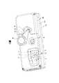
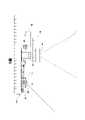
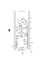
圖1為本發明光學切換式深度感測相機的外觀示意圖;圖2為本發明光學切換式深度感測相機的分解示意圖;圖3、圖4為本發明光學切換式深度感測相機的窄角長焦模式示意圖;圖5、圖6為本發明光學切換式深度感測相機的廣角短焦模式示意圖;圖7、圖8為本發明光學切換式深度感測相機之光學模組的示意圖;以及圖9為本發明光學切換式深度感測相機之切換機構的判斷流程示意圖。1 is a schematic view of the appearance of the optical switching depth sensing camera of the present invention; FIG. 2 is an exploded schematic view of the optical switching depth sensing camera of the present invention; FIGS. 3 and 4 are narrow angles of the optical switching depth sensing camera of the present invention Schematic diagram of the telephoto mode; FIG. 5 and FIG. 6 are schematic diagrams of the wide-angle short focus mode of the optical switching depth sensing camera of the present invention; FIG. 7 and FIG. 8 are schematic diagrams of the optical module of the optical switching depth sensing camera of the present invention; and FIG. 9 is a schematic diagram of the judgment flow of the switching mechanism of the optical switching depth sensing camera of the present invention.
茲有關本發明之技術內容及詳細說明,配合圖式說明如下。The technical content and detailed description of the present invention are described as follows in conjunction with the drawings.
請參閱圖1至圖6所示。其中,圖1為本發明光學切換式深度感測相機的外觀示意圖,圖2為本發明光學切換式深度感測相機的分解示意圖。圖3、圖4為本發明光學切換式深度感測相機的窄角長焦模式示意圖。圖5、圖6為本發明光學切換式深度感測相機的廣角短焦模式示意圖。Please refer to Figure 1 to Figure 6. 1 is a schematic diagram of the appearance of the optical switching depth sensing camera of the present invention, and FIG. 2 is an exploded schematic diagram of the optical switching depth sensing camera of the present invention. FIG. 3 and FIG. 4 are schematic diagrams of the narrow-angle telephoto mode of the optical switching depth sensing camera of the present invention. FIG. 5 and FIG. 6 are schematic diagrams of wide-angle and short-focus modes of the optical switching depth sensing camera of the present invention.
在本發明之第一實施例中,本發明所提出的光學切換式深度感測相機可包括紅外光雷射模組10、影像感測器20、第一光學鏡頭30、第二光學鏡頭40、切換機構50以及微控制器60。其中,紅外光雷射模組10輸出紅外光雷射(IR laser)。影像感測器20接收紅外光雷射。第一光學鏡頭30固設於影像感測器20之上。第二光學鏡頭40可移除地配置於第一光學鏡頭30之上。切換機構50耦接第二光學鏡頭40且控制第二光學鏡頭40的位置。微控制器60耦接影像感測器20、切換機構50以及紅外光雷射模組10。在本發明之所述第一實施例中,第一光學鏡頭30的焦距可大於第二光學鏡頭40的焦距,且第一光學鏡頭30的視角可小於第二光學鏡頭40的視角。即第一光學鏡頭30可以是窄角鏡頭(narrow angle lens),其具有長焦距的特性。第二光學鏡頭40可以是廣角鏡頭(wide angle lens),其具有短焦距的特性。此外,第一光學鏡頭30的焦距可介於2公尺與30公尺之間,第二光學鏡頭40的焦距可介於15公分與3公尺之間或可介於70公分至4公尺之間,即第一光學鏡頭30的焦距與第二光學鏡頭40的焦距可以部份重疊,除部分重疊之外,第一光學鏡頭30的焦距大於第二光學鏡頭40的焦距。In the first embodiment of the present invention, the optical switching depth sensing camera proposed by the present invention may include an
進一步而言,所述紅外光雷射可以是單一發光角(field of illumination,FoI)而同時可涵蓋窄角與廣角兩種鏡頭的範圍,抑或是分別提供窄角與廣角的發射光源的兩組雷射。在本發明之所述第一實施例中,紅外光雷射模組10可包括第一發光單元11以及第二發光單元12。其中,第一發光單元11於第一光學鏡頭30之上無第二光學鏡頭40時輸出至少部分紅外光雷射。第二發光單元12於第一光學鏡頭30之上有第二光學鏡頭40時輸出至少部分紅外光雷射。在本發明之所述第一實施例中,所述紅外光雷射模組10的第一發光單元11以及第二發光單元12的輸出波長可以介於800奈米(nm)與1350奈米(nm)之間,且進一步而言,第一發光單元11以及第二發光單元12均可在其出光方向上整合有擴散片(圖中未示),所述擴散片可依據所需要的出光角度而進行調整。在本發明之所述第一實施例中,第一發光單元11可以被設計為窄角長焦模式時使用(即影像感測器20的光路上僅具有第一光學鏡頭30),第二發光單元12可以被設計為廣角短焦模式時使用(即影像感測器20的光路上同時地具有第一光學鏡頭30以及第二光學鏡頭40)。Further, the infrared laser can be a single field of illumination (FoI) that can cover both narrow-angle and wide-angle lens ranges, or two groups of light sources that respectively provide narrow-angle and wide-angle emitting light sources. laser. In the first embodiment of the present invention, the
其中,切換機構50可包括步進馬達、伺服馬達以及線性致動器(linear actuator)的其中至少一者。所述線性致動器還可以包括形狀記憶合金(shape memory alloys,SMA),所述SMA是一種能夠記憶原有形狀的材料,當SMA在低於相變態溫度時受到一有限度的塑性變形後,可藉由加熱的方式使SMA恢復到變形前的原始形狀,這種特殊的現象稱為形狀記憶效應(shape memory effect,SME)。在本發明之所述第一實施例中,切換機構50可包括撥桿51、樞軸52以及馬達53,其中,撥桿51的一端配置有第二光學鏡頭40,撥桿51的另一端配置有樞軸52,且撥桿51藉由樞軸52而受馬達53的驅動,以進一步地控制第二光學鏡頭40的位置是配置於第一光學鏡頭30之上,或自第一光學鏡頭30之上移開。The
進一步而言,微控制器60可通過飛時測距(time of flight,ToF)方法自影像感測器20獲得包括探測深度的飛時測距資訊(圖中未示),從而使得微控制器60得知待測區域的立體態樣,且微控制器60可依據飛時測距資料控制紅外光雷射模組10輸出紅外光雷射的調制頻率(modulation frequency,或稱為調變頻率)以及功率。所述調制頻率需要與影像感測器20的畫面更新速率(frame rate)(或可稱之為幀率)以及影像感測器20與待測區域的距離維持有固定之倍頻比例關係,為此紅外光雷射模組10才能同時將紅外光雷射的調制頻率同步提供給影像感測器20做為深度距離。Further, the
如圖3以及圖4所示,當影像感測器20的光路上僅具有第一光學鏡頭30時,微控制器60可控制第一發光單元11輸出較高功率的紅外光雷射,可以使紅外光雷射位於感測區域的範圍包覆第一光學鏡頭30之視角位於感測區域的範圍,以滿足窄角長焦模式的需求。如圖5以及圖6所示,當影像感測器20的光路上同時地具有第一光學鏡頭30以及第二光學鏡頭40時,微控制器60可控制第二發光單元12輸出較低功率的紅外光雷射,可以使紅外光雷射位於感測區域的範圍包覆第一光學鏡頭30結合第二光學鏡頭40後之視角位於感測區域的範圍,以滿足廣角短焦模式的需求。前述將第一光學鏡頭30結合第二光學鏡頭40可改變整個光學系統的光程(optical path length)以及焦距(focal length),尤其是將光學系統的視角(field of view,FoV)(或可稱之為視野)擴大,讓鏡頭在近距離時,仍然能夠涵蓋足夠的範圍。As shown in FIG. 3 and FIG. 4 , when the optical path of the
進一步地,所述微控制器60可以是影像處理晶片(image process IC)或影像感測單晶片(image sensor SoC),在微控制器60運行所述飛時測距方法的同時,可以通過切換機構50而決定第一光學鏡頭30或第二光學鏡頭40是否位於影像感測器20的光軸上,使得微控制器60能夠快速地得知影像感測器20與待測區域的距離。微控制器60可針對不斷更新的所述距離,立即地控制第一光學鏡頭30以及第二光學鏡頭40的位置,以使第一光學鏡頭30以及第二光學鏡頭40的其中至少一者所具有的焦距以及視角可以正確地對應待測區域,使影像感測器20可以獲得完整(待測區域位於視角內)且清晰(待測區域的位置符合焦距)的影像。Further, the
在本發明之所述第一實施例中,所述光學切換式深度感測相機可更包括上殼體101、中殼體102以及下殼體103。其中,上殼體101穿設有第一通孔111、第二通孔121以及第三通孔131。第一通孔111用以使樞軸52穿設於其中,且第一通孔111周圍形成矛形的凹槽以限制撥桿51的旋轉範圍。第二通孔121供第一光學鏡頭30自上殼體101之外接收紅外光雷射。第三通孔131供紅外光雷射模組10將紅外光雷射輸出於上殼體101之外。中殼體102夾設於上殼體101以及下殼體103之間,且用以固定紅外光雷射模組10、影像感測器20以及微控制器60,且本發明之所述第一實施例中,可更包括第一連接埠104以及第二連接埠105,所述第一連接埠104以及第二連接埠105可用於供應電源、傳輸資料、遠端控制等用途。In the first embodiment of the present invention, the optical switching depth sensing camera may further include an
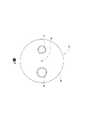
請參閱圖7、圖8所示,為本發明光學切換式深度感測相機之光學模組的示意圖,其餘元件編號請參閱前述內容,在此不再贅述。Please refer to FIG. 7 and FIG. 8 , which are schematic diagrams of the optical module of the optical switchable depth-sensing camera of the present invention. Please refer to the above-mentioned content for other component numbers, and will not be repeated here.
在本發明之第二實施例中,與前述第一實施例大致相同,惟切換機構51’、第一光學鏡頭30以及第二光學鏡頭40構成光學模組50’,且第一光學鏡頭30以及第二光學鏡頭40相對於影像感測器20都是可移動地。In the second embodiment of the present invention, it is substantially the same as the aforementioned first embodiment, except that the
如圖7所示,切換機構51’是圓盤狀,切換機構51’耦接第一光學鏡頭30以及第二光學鏡頭40,且切換機構51’可通過樞軸52受馬達53的驅動,以改變第一光學鏡頭30以及第二光學鏡頭40的位置是否位於影像感測器20之上。As shown in FIG. 7 , the
如圖8所示,與前述圖7不同的是切換機構51”、第一光學鏡頭30以及第二光學鏡頭40構成光學模組50”,切換機構51”僅耦接第二光學鏡頭40,但第一光學鏡頭30並不是固設於影像感測器20之上,第一光學鏡頭30以及第二光學鏡頭40相對於影像感測器20都是可移動地。切換機構51”可通過樞軸52受馬達53的驅動。其中,第一光學鏡頭30可配置於滑軌200中,且第一光學鏡頭30可通過切換機構51”的推動而在滑軌200中改變位置。As shown in FIG. 8 , the difference from the aforementioned FIG. 7 is that the
在使用本發明所述任一光學切換式深度感測相機時,紅外光雷射模組10輸出紅外光雷射至待測區域,影像感測器20可通過第一光學鏡頭30以及第二光學鏡頭40的其中至少一者而接收反射自待測區域的紅外光雷射。且進一步地,微控制器60可通過飛時測距(ToF)方法獲得包括探測深度的飛時測距資訊,從而使得微控制器60得知待測區域的立體態樣。並且,在微控制器60運行所述飛時測距方法的同時,可以通過切換機構50、51’、51”而決定第一光學鏡頭30或第二光學鏡頭40是否位於影像感測器20的光軸上,使得微控制器60能夠快速地得知影像感測器20與待測區域的距離。微控制器60可針對不斷更新的所述距離,立即地控制第一光學鏡頭30以及第二光學鏡頭40的位置,以使第一光學鏡頭30以及第二光學鏡頭40的其中至少一者所具有的焦距以及視角可以正確地對應待測區域,使影像感測器20可以獲得完整(待測區域位於視角內)且清晰(待測區域的位置符合焦距)的影像。When using any of the optical switching depth sensing cameras described in the present invention, the
請參閱圖9所示,為本發明光學切換式深度感測相機之切換機構50、51’、51”的判斷流程示意圖,其餘元件編號請參閱前述內容,在此不再贅述。在微控制器60運行所述飛時測距方法時,微控制器60會判斷待測區域是否適用廣角短焦的模式(步驟S1)。若微控制器60判斷待測區域適用廣角短焦時,紅外光雷射模組10啟動第二發光單元12,且微控制器60依據飛時測距資料控制紅外光雷射模組10輸出紅外光雷射的調制頻率以及功率(步驟S2)。繼而,通過切換機構50、51’、51”控制第一光學鏡頭30以及第二光學鏡頭40的位置,使影像感測器20運行於廣角短焦模式(步驟S3)。此外,微控制器60可進一步地結合廣角短焦模式的深度資訊以及飛時測距時關於窄角長焦模式的深度資訊,作3D深度的資料融合(depth data fusion),依據事先的視角校正資料表(圖中未示),將不同視角以及距離所蒐集所量測的深度資訊作疊加(overlapping)以及轉換,達成為全深度感測的效果。Please refer to FIG. 9 , which is a schematic diagram of the judgment flow of the switching
若微控制器60判斷待測區域不適用廣角短焦時,紅外光雷射模組10啟動第一發光單元11,且微控制器60依據飛時測距資料控制紅外光雷射模組10輸出紅外光雷射的調制頻率以及功率(步驟S4)。繼而,通過切換機構50、51’、51”控制第一光學鏡頭30以及第二光學鏡頭40的位置,使影像感測器20運行於窄角長焦模式(步驟S5)。此外,微控制器60可進一步地結合窄角長焦模式的深度資訊以及飛時測距時關於廣角短焦模式的深度資訊,作3D深度的資料融合。微控制器60可依據事先的視角校正資料表,將不同視角以及距離所蒐集所量測的深度資訊作疊加以及轉換,達成為全深度感測的效果。If the
為此,本發明所述的光學切換式深度感測相機,可以解決現有技術對於結構複雜或相對於影像感測器正在移動的非靜止目標而言,很容易會因為目標移動幅度過大而超出光學鏡頭的焦距範圍或視角之外的技術問題,達到方便操作使用之目的。For this reason, the optical switching depth sensing camera of the present invention can solve the problem that in the prior art, for a non-stationary target with a complex structure or moving relative to the image sensor, it is easy for the target to move too much and exceed the optical speed. Technical problems beyond the focal length range or angle of view of the lens to facilitate operation and use.
以上所述,僅為本發明較佳具體實施例之詳細說明與圖式,惟本發明之特徵並不侷限於此,並非用以限制本發明,本發明之所有範圍應以下述之申請專利範圍為準,凡合於本發明申請專利範圍之精神與其類似變化之實施例,皆應包括於本發明之範疇中,任何熟悉該項技藝者在本發明之領域內,可輕易思及之變化或修飾皆可涵蓋在以下本發明之專利範圍。The above descriptions are only detailed descriptions and drawings of the preferred embodiments of the present invention, but the features of the present invention are not limited thereto, and are not intended to limit the present invention. The entire scope of the present invention should be defined as the following claims All the embodiments that conform to the spirit of the scope of the patent application of the present invention and its similar variations shall be included in the scope of the present invention. Modifications are all encompassed by the following patentable scope of the present invention.
本說明書所附圖式繪示之結構、比例、大小、元件數量等,均僅用以配合說明書所揭示之內容,以供熟悉此技術之人士瞭解與閱讀,並非用以限定本發明可實施之限定條件,故不具技術上之實質意義,任何結構之修飾、比例關係之改變或大小之調整,在不影響本發明所能產生之功效及所能達成之目的下,均應落在本發明所揭示之技術內容得能涵蓋之範圍內。The structures, proportions, sizes, number of components, etc. shown in the drawings in this specification are only used to cooperate with the contents disclosed in the specification for the understanding and reading of those skilled in the art, and are not intended to limit the implementation of the present invention. Therefore, it has no technical significance, and any modification of the structure, change of the proportional relationship or adjustment of the size will not affect the performance of the present invention.The effect and the achievable purpose should fall within the scope that the technical content disclosed in the present invention can cover.
10:紅外光雷射模組10: Infrared laser module
11:第一發光單元11: The first light-emitting unit
12:第二發光單元12: The second light-emitting unit
30:第一光學鏡頭30: The first optical lens
40:第二光學鏡頭40: Second optical lens
50:切換機構50: Switch Mechanism
51:撥桿51: lever
52:樞軸52: Pivot
101:上殼體101: Upper shell
102:中殼體102: Middle shell
103:下殼體103: Lower shell
Claims (10)
Translated fromChinesePriority Applications (3)
| Application Number | Priority Date | Filing Date | Title |
|---|---|---|---|
| TW109144422ATWI777329B (en) | 2020-12-16 | 2020-12-16 | Optical switchable depth sensing camera |
| CN202110116902.1ACN114636986A (en) | 2020-12-16 | 2021-01-28 | Optical switchable depth-sensing camera |
| US17/211,221US20220187465A1 (en) | 2020-12-16 | 2021-03-24 | Optical switchable depth sensing camera |
Applications Claiming Priority (1)
| Application Number | Priority Date | Filing Date | Title |
|---|---|---|---|
| TW109144422ATWI777329B (en) | 2020-12-16 | 2020-12-16 | Optical switchable depth sensing camera |
Publications (2)
| Publication Number | Publication Date |
|---|---|
| TW202225813A TW202225813A (en) | 2022-07-01 |
| TWI777329Btrue TWI777329B (en) | 2022-09-11 |
Family
ID=81942366
Family Applications (1)
| Application Number | Title | Priority Date | Filing Date |
|---|---|---|---|
| TW109144422ATWI777329B (en) | 2020-12-16 | 2020-12-16 | Optical switchable depth sensing camera |
Country Status (3)
| Country | Link |
|---|---|
| US (1) | US20220187465A1 (en) |
| CN (1) | CN114636986A (en) |
| TW (1) | TWI777329B (en) |
Citations (6)
| Publication number | Priority date | Publication date | Assignee | Title |
|---|---|---|---|---|
| EP0598703B1 (en)* | 1986-12-24 | 2000-08-09 | Minolta Co., Ltd. | Focal length switchover camera |
| CN2490596Y (en)* | 2001-07-18 | 2002-05-08 | 陈建全 | Compound-eye multi-step automatic zoom photography device |
| TWI368100B (en)* | 2006-02-10 | 2012-07-11 | Hon Hai Prec Ind Co Ltd | Auto-focusing module of digital camera |
| CN106199888A (en)* | 2015-02-02 | 2016-12-07 | 杜兴 | Optical path changes system and imaging device |
| TW201939151A (en)* | 2018-01-25 | 2019-10-01 | 台灣東電化股份有限公司 | Optical system |
| TWI708988B (en)* | 2019-05-21 | 2020-11-01 | 吳政鋒 | Multi-lens transposition device |
Family Cites Families (8)
| Publication number | Priority date | Publication date | Assignee | Title |
|---|---|---|---|---|
| US6629641B2 (en)* | 2000-06-07 | 2003-10-07 | Metrologic Instruments, Inc. | Method of and system for producing images of objects using planar laser illumination beams and image detection arrays |
| JP2000028900A (en)* | 1998-07-10 | 2000-01-28 | Olympus Optical Co Ltd | Interchangeable lens and camera system |
| TW200844535A (en)* | 2007-05-02 | 2008-11-16 | Altek Corp | Zoom control mechanism |
| CN104865801B (en)* | 2015-06-01 | 2017-03-01 | 京东方科技集团股份有限公司 | Exposure device |
| CN207992663U (en)* | 2017-12-05 | 2018-10-19 | 宁波舜宇光电信息有限公司 | Structured light projecting device, depth camera and electronic equipment |
| KR20190117176A (en)* | 2018-04-06 | 2019-10-16 | 삼성전기주식회사 | Infrared camera module, image sensor thereof, and electronic device |
| CN108833889B (en)* | 2018-08-22 | 2020-06-23 | Oppo广东移动通信有限公司 | Control method and device, depth camera, electronic device and readable storage medium |
| KR20210131510A (en)* | 2020-04-23 | 2021-11-03 | 삼성디스플레이 주식회사 | Apparatus for forming line beam |
- 2020
- 2020-12-16TWTW109144422Apatent/TWI777329B/enactive
- 2021
- 2021-01-28CNCN202110116902.1Apatent/CN114636986A/enactivePending
- 2021-03-24USUS17/211,221patent/US20220187465A1/ennot_activeAbandoned
Patent Citations (6)
| Publication number | Priority date | Publication date | Assignee | Title |
|---|---|---|---|---|
| EP0598703B1 (en)* | 1986-12-24 | 2000-08-09 | Minolta Co., Ltd. | Focal length switchover camera |
| CN2490596Y (en)* | 2001-07-18 | 2002-05-08 | 陈建全 | Compound-eye multi-step automatic zoom photography device |
| TWI368100B (en)* | 2006-02-10 | 2012-07-11 | Hon Hai Prec Ind Co Ltd | Auto-focusing module of digital camera |
| CN106199888A (en)* | 2015-02-02 | 2016-12-07 | 杜兴 | Optical path changes system and imaging device |
| TW201939151A (en)* | 2018-01-25 | 2019-10-01 | 台灣東電化股份有限公司 | Optical system |
| TWI708988B (en)* | 2019-05-21 | 2020-11-01 | 吳政鋒 | Multi-lens transposition device |
Non-Patent Citations (4)
| Title |
|---|
| Multi Turret - Three Lenses at Once on Your Camera,YouTube, (https://www.youtube.com/watch?v=YuGUdgvjvwI), CineD,2019/4/12上傳* |
| 寶雅 時尚家電 三種鏡頭轉轉秒切換E books N62 轉盤式三合一特效鏡頭,YouTube, (https://www.youtube.com/watch?v=_tCbQ3g3qgU),POYA 寶雅,2018/10/23上傳* |
| 雙鏡頭的創始者——柯達V570「經典老機」,網頁內容, (https://kknews.cc/photography/p95nqj8.html),匯攝影,2018/10/23發表* |
| 雙鏡頭的創始者——柯達V570「經典老機」,網頁內容, (https://kknews.cc/photography/p95nqj8.html),匯攝影,2018/10/23發表。 |
Also Published As
| Publication number | Publication date |
|---|---|
| CN114636986A (en) | 2022-06-17 |
| US20220187465A1 (en) | 2022-06-16 |
| TW202225813A (en) | 2022-07-01 |
Similar Documents
| Publication | Publication Date | Title |
|---|---|---|
| US10877281B2 (en) | Compact optical system with MEMS scanners for image generation and object tracking | |
| US10310284B1 (en) | Apparatus and method for projecting three-dimensional holographic images | |
| CN111727398A (en) | Integrated Augmented Reality Head Mounted Display for Pupil Steering | |
| US11277551B2 (en) | Multiple optical path imaging techniques and shared emitter for active depth sensing techniques | |
| JPH11508057A (en) | Imaging device with three-dimensional measurement and focus-related convergence correction and method of use | |
| US8633892B2 (en) | Projection display device having a light combining unit | |
| US12265235B2 (en) | Detection apparatus, detection method, and spatial projection apparatus | |
| TWM523106U (en) | Optical device | |
| US7938542B2 (en) | Optical swiveling device for imaging and/or projection of an object scene | |
| CN107644438A (en) | Image processing apparatus, related depth estimation system and depth estimation method | |
| KR102512680B1 (en) | A distance measuring device for golf | |
| TWI777329B (en) | Optical switchable depth sensing camera | |
| US11092724B1 (en) | Apparatus and method for projecting three-dimensional holographic images | |
| Bothe et al. | Compact 3D camera | |
| CN113747141A (en) | Electronic equipment and depth image shooting method | |
| KR101502168B1 (en) | Image photographing apparatus | |
| TWI672527B (en) | Projection device capable of adjusting virtual image distance and projection method thereof | |
| US11092821B1 (en) | Apparatus and method for projecting three-dimensional holographic images | |
| JP2005057541A (en) | Spectroscopic camera head | |
| US20180364558A1 (en) | Photo assistant device | |
| JP2004170305A (en) | Three-dimensional shape measuring method and three-dimensional shape measuring device | |
| KR102512681B1 (en) | A distance measuring device for golf | |
| US20240345293A1 (en) | Adjustable optical aperture for an imaging system | |
| CN109005316B (en) | Image sensor module | |
| CN116320709A (en) | Camera component, distance measuring method, distance measuring device, electronic equipment and medium |
Legal Events
| Date | Code | Title | Description |
|---|---|---|---|
| GD4A | Issue of patent certificate for granted invention patent |