Movatterモバイル変換


[0]ホーム

URL:


TWI774151B - Chassis and cage thereof - Google Patents

Chassis and cage thereof
Download PDF

Info

Publication number
TWI774151B
TWI774151BTW109143312ATW109143312ATWI774151BTW I774151 BTWI774151 BTW I774151BTW 109143312 ATW109143312 ATW 109143312ATW 109143312 ATW109143312 ATW 109143312ATW I774151 BTWI774151 BTW I774151B
Authority
TW
Taiwan
Prior art keywords
clamping
sliding
bracket
buckle
expansion box
Prior art date
Application number
TW109143312A
Other languages
Chinese (zh)
Other versions
TW202224525A (en
Inventor
黎映
鄭永亮
Original Assignee
緯創資通股份有限公司
Priority date (The priority date is an assumption and is not a legal conclusion. Google has not performed a legal analysis and makes no representation as to the accuracy of the date listed.)
Filing date
Publication date
Application filed by 緯創資通股份有限公司filedCritical緯創資通股份有限公司
Publication of TW202224525ApublicationCriticalpatent/TW202224525A/en
Application grantedgrantedCritical
Publication of TWI774151BpublicationCriticalpatent/TWI774151B/en

Links

Images

Classifications

Landscapes

Abstract

A chassis includes a cage. The cage includes a body, a holding element and a buckling element. The body includes a first sliding portion, a mating portion and an accommodating area. The accommodating area includes a guide portion. The guide portion and the first sliding portion are disposed in two sides of the accommodating area respectively. The mating portion is disposed in the accommodating area and the mating portion is away from the guide portion. The holding element is slidably connected to the first sliding portion. The buckling element is disposed on the holding element. The buckling element buckles the mating portion.

Description

Translated fromChinese
機箱及其擴充匣Chassis and its expansion box

一種機箱及其擴充匣,尤指一種固定擴充卡之擴充匣。A case and its expansion box, especially an expansion box for fixing expansion cards.

機架式伺服機台之機櫃一般配置多個可滑移之伺服器單元,伺服器單元可承載大量工作單元(如硬碟或快閃記憶體),以協同執行雲端的大數據運算。伺服器的機箱內安裝多個擴充模組,每個擴充模組內置放有多張擴充卡。一般擴充模組具有固定結構,支撐在擴充卡側邊,但固定結構與擴充卡側端之間的空間有限,若安裝長度較長的擴充卡時,固定結構與擴充卡側端之間的空間將會縮小,使傳輸線無法插入該空間與擴充卡側端電性連接。另外,一種可旋轉式的固定結構可旋轉開啟擴充卡側邊或可旋轉覆蓋在擴充卡側邊使用,旋轉路徑需佔用較多的設置空間,且旋轉式的固定結構需一手先拆解固定結構上的鎖扣,再手動將固定結構旋轉至頂側才可拆除或安裝擴充卡,操作不便且費力。The cabinet of a rack-mounted server machine is generally equipped with multiple slidable server units. The server units can carry a large number of work units (such as hard disks or flash memory) to collaboratively perform big data operations in the cloud. Multiple expansion modules are installed in the chassis of the server, and each expansion module contains multiple expansion cards. Generally, the expansion module has a fixed structure and is supported on the side of the expansion card, but the space between the fixed structure and the side of the expansion card is limited. It will shrink so that the transmission line cannot be inserted into the space to be electrically connected to the side of the expansion card. In addition, a rotatable fixed structure can be rotated to open the side of the expansion card or can be rotated to cover the side of the expansion card for use. The rotation path needs to take up a lot of installation space, and the rotating fixed structure needs to be disassembled by one hand. After removing or installing the expansion card by manually rotating the fixing structure to the top side, the operation is inconvenient and laborious.

有鑑於此,依據一些實施例,一種擴充匣包括托架、夾持件及卡接件。托架包括第一滑移部、扣接部及插卡區。插卡區包含導軌部,導軌部與第一滑移部分別設置於插卡區之兩側,扣接部設於插卡區且遠離導軌部之一側。夾持件滑設於第一滑移部。卡接件設於夾持件,卡接件適於卡掣扣接部。In view of this, according to some embodiments, an expansion box includes a bracket, a clip and a clip. The bracket includes a first sliding part, a buckle part and a card insertion area. The card insertion area includes a guide rail part, the guide rail part and the first sliding part are respectively arranged on two sides of the card insertion area, and the buckle part is arranged on a side of the card insertion area away from the guide rail part. The clamping piece is slidably arranged on the first sliding portion. The clamping part is arranged on the clamping part,The clipping part is suitable for clipping the buckle part.

在一些實施例中,夾持件適於沿第一滑移部位移於第一位置及第二位置之間,在夾持件位於第一位置時,夾持件遠離導軌部且卡接件分離於扣接部,在夾持件位於第二位置時,夾持件接近導軌部且卡接件卡掣於扣接部。In some embodiments, the clamping member is adapted to be displaced between the first position and the second position along the first sliding portion, and when the clamping member is located at the first position, the clamping member is away from the guide rail portion and the clamping member is separated In the buckle portion, when the clamping member is located at the second position, the clamping member is close to the guide rail portion and the clamping member is clamped to the buckle portion.

在一些實施例中,卡接件及扣接部之一設有復位結構,在夾持件朝第一位置移動時,復位結構適於使卡接件離開扣接部。In some embodiments, one of the clamping member and the buckle portion is provided with a reset structure, and when the clamping member moves toward the first position, the reset structure is adapted to make the clamp member leave the buckle portion.

在一些實施例中,卡接件包括第一止擋件、第二止擋件、卡接塊及復位件,卡接塊設置於第一止擋件與第二止擋件之間,復位件設置於卡接塊與第二止擋件之間,卡接塊之一側邊設有卡接部,卡接部套設於第一止擋件且適於卡掣或脫離扣接部。In some embodiments, the clamping part includes a first stopper, a second stopper, a clamping block and a reset part, the clamping block is disposed between the first stopper and the second stopper, and the reset part It is arranged between the clamping block and the second stopper, one side of the clamping block is provided with a clamping part, the clamping part is sleeved on the first stopper and is suitable for clamping or disengaging the clamping part.

在一些實施例中,卡接塊相反卡接部之一側邊設有凹槽,第二止擋件朝向卡接塊設有突塊,復位件之一端限位於凹槽,另一端套設於突塊。In some embodiments, a groove is formed on one side of the opposite clamping portion of the clamping block, a protrusion is formed on the second stopper facing the clamping block, one end of the restoring member is limited to the groove, and the other end is sleeved in the groove. bump.

在一些實施例中,扣接部包含結合塊,結合塊定位於托架,結合塊設有扣孔及導引面,導引面適於導引卡接部定位於扣孔內。In some embodiments, the buckle portion includes a combination block, the combination block is positioned on the bracket, the combination block is provided with a button hole and a guide surface, and the guide surface is suitable for guiding the buckle portion to be positioned in the button hole.

在一些實施例中,扣接部設有扣孔,卡接部設有導引面,導引面適於導引卡接部至扣孔定位。In some embodiments, the buckle portion is provided with a button hole, the buckle portion is provided with a guide surface, and the guide surface is suitable for guiding the buckle portion to the button hole for positioning.

在一些實施例中,卡接件包括第一止擋件及復位件,復位件一側設有卡接部,復位件之卡接部穿設於第一止擋件,且適於卡掣或脫離扣接部。In some embodiments, the clipping member includes a first stopper and a reset member, a clipping portion is provided on one side of the reset member, and the clipping portion of the reset member passes through the first stopper and is suitable for clipping or Disengage the buckle.

在一些實施例中,卡接件包含彈片,彈片設有朝向托架延伸之突部,突部適於自動卡掣或脫離扣接部。In some embodiments, the clip includes an elastic piece, and the elastic piece is provided with an extension toward the bracket.The protruding portion is adapted to be automatically locked or released from the buckle portion.

在一些實施例中,在一些實施例中,托架具有底板及側板,底板與側板連接且具有一角度關係,扣接部設於側板,第一滑移部設於底板,扣接部與第一滑移部具有一角度關係。In some embodiments, in some embodiments, the bracket has a bottom plate and a side plate, the bottom plate is connected with the side plate and has an angular relationship, the buckle portion is provided on the side plate, the first sliding portion is provided on the bottom plate, and the buckle portion is connected with the first A sliding portion has an angular relationship.

在一些實施例中,托架包括第二滑移部,第二滑移部設於側板,夾持件對接於第二滑移部,第二滑移部與第一滑移部具有一角度關係。In some embodiments, the bracket includes a second sliding portion, the second sliding portion is provided on the side plate, the clamping member is butted to the second sliding portion, and the second sliding portion has an angular relationship with the first sliding portion .

在一些實施例中,夾持件包括第三滑移部及第四滑移部,第三滑移部與第四滑移部具有一角度關係,第三滑移部及第四滑移部適於對接於托架之側板與底板。In some embodiments, the clamping member includes a third sliding portion and a fourth sliding portion, the third sliding portion and the fourth sliding portion have an angular relationship, and the third sliding portion and the fourth sliding portion are suitable for It is connected to the side plate and the bottom plate of the bracket.

在一些實施例中,第一滑移部包含第一長槽以及第一鎖接件,第一鎖接件穿入第一長槽且鎖接於夾持件,第三滑移部包含第三長槽以及第三鎖接件,第三鎖接件穿入第三長槽且鎖接於托架,第四滑移部包含第四長槽以及第四鎖接件,第四鎖接件穿入第四長槽且鎖接於托架。In some embodiments, the first sliding portion includes a first long groove and a first locking member, the first locking member penetrates the first long groove and is locked to the clamping member, and the third sliding portion includes a third A long slot and a third locking piece, the third locking piece penetrates the third long slot and is locked to the bracket, the fourth sliding part includes a fourth long slot and a fourth locking piece, the fourth locking piece passes through into the fourth long slot and locked to the bracket.

在一些實施例中,第二滑移部包含反折部及溝槽,反折部自側板一側轉折,溝槽位於反折部與側板之間。In some embodiments, the second sliding portion includes a folded portion and a groove, the folded portion is turned from one side of the side plate, and the groove is located between the folded portion and the side plate.

在一些實施例中,托架遠離導軌部之一側包括多個限位部,多個限位部適於限位於夾持件一側。In some embodiments, a side of the bracket away from the guide rail portion includes a plurality of limit portions, and the plurality of limit portions are adapted to be limited to one side of the clamping member.

在一些實施例中,擴充匣更包括限位件,設於夾持件朝向托架之一側面,限位件側面具有凹部。In some embodiments, the expansion box further includes a limiting member disposed on a side of the clamping member facing the bracket, and a side surface of the limiting member has a concave portion.

在一些實施例中,擴充匣更包括限位件,限位件設於夾持件朝向托架之一側面,限位件側面具有交互排列之多個凹部與多個凸部。In some embodiments, the expansion box further includes a limiter, and the limiter is arranged on the clampingThe part faces one side of the bracket, and the side surface of the limiting part has a plurality of concave parts and a plurality of convex parts which are alternately arranged.

在一些實施例中,夾持件包括握持部,握持部鄰近於卡接件。In some embodiments, the clip includes a grip portion adjacent to the catch.

在一些實施例中,提出一種機箱,包括殼體及擴充匣,擴充匣設於殼體內,擴充匣包括托架、夾持件及卡接件,托架包括第一滑移部、扣接部及插卡區。插卡區包含導軌部,導軌部與第一滑移部分別設置於插卡區之兩側,扣接部設於插卡區遠離導軌部之一側,夾持件滑設於第一滑移部,卡接件設於夾持件,適於卡掣扣接部。In some embodiments, a case is provided, which includes a casing and an expansion box, the expansion box is arranged in the casing, the expansion box includes a bracket, a clamping part and a clamping part, and the bracket includes a first sliding part and a buckle part and card slot. The card insertion area includes a guide rail part, the guide rail part and the first sliding part are respectively arranged on both sides of the card insertion area, the buckle part is arranged on a side of the card insertion area away from the guide rail part, and the clamping part is slidably arranged on the first sliding part The clipping part is arranged on the clamping part and is suitable for clipping the clipping part.

綜上,依據一些實施例,托架適用於不同長度之擴充模組安裝,夾持件滑移在托架側邊且覆蓋擴充模組,在擴充模組因震動落摔測試、運送、人為或自然因素而被震動時,夾持件可以避免擴充模組鬆脫或掉落。其次,依據一些實施例,夾持件的握持部與卡接件為鄰近設置,供單手即可操作卡接件脫離托架,且推動握持部將夾持件滑移、脫離擴充模組。另外,依據一些實施例,夾持件以滑動方式組裝在托架側邊,托架側邊僅需提供夾持件可滑動的空間即可,佔用空間少。此外,依據一些實施例,擴充模組側邊插接端外露在夾持件形成的框口內部,方便傳輸線電性連接插接端。To sum up, according to some embodiments, the bracket is suitable for the installation of expansion modules of different lengths, and the clamping member slides on the side of the bracket and covers the expansion module. When it is shaken by natural factors, the clamp can prevent the expansion module from loosening or falling. Secondly, according to some embodiments, the gripping portion of the clamping member and the engaging member are disposed adjacent to each other, so that the engaging member can be detached from the bracket by one-handed operation, and the gripping portion can be pushed to slide the gripping member out of the expansion mold. Group. In addition, according to some embodiments, the clamping member is assembled on the side of the bracket in a sliding manner, and the side of the bracket only needs to provide a space for the clamping member to slide, which occupies less space. In addition, according to some embodiments, the side plug end of the expansion module is exposed inside the frame opening formed by the clamping member, so as to facilitate the electrical connection of the transmission line to the plug end.

100:機箱100: Chassis

101:殼體101: Shell

200:擴充匣200: Expansion Box

300:轉接板300: Adapter board

301:電性連接埠301: Electrical connection port

400:擴充模組400: Expansion Module

401:電性連接埠401: Electrical port

402:插接端402: plug end

403:側端403: side end

1:托架1: Bracket

1a:底板1a: Bottom plate

1b:側板1b: side panel

10:插卡區10: Card area

102:導軌部102: Rail part

11:第一滑移部,第一長槽,第一鎖接件11: The first sliding part, the first long groove, the first locking piece

12:扣接部,結合塊12: Buckle part, combined block

121:扣孔121: button hole

122:導引面122: Guide surface

14:延伸部14: Extensions

15:第二滑移部,反折部,溝槽15: The second sliding part, the folded part, the groove

18:限位部,擋板18: Limiting part, baffle

2:夾持件2: Clamps

20:框口20: Frame mouth

21:握持部21: Grip

25:側端25: side end

26:第三滑移部,第三長槽,第三鎖接件26: The third sliding part, the third long slot, the third locking piece

27:第四滑移部,第四長槽,第四鎖接件27: The fourth sliding part, the fourth long slot, the fourth locking piece

3:卡接件3: Clips

31:第一止擋件31: First stopper

311:穿孔311: Perforation

32:第二止擋件32: Second stopper

325:突塊325: Bump

33:卡接塊33: Snap block

331:卡接部331: Snap part

332:扳動部332: Wrench Department

333:滑塊333: Slider

334:側面334: Side

335:凹槽335: Groove

336:導引面336: Guide Surface

35:復位件35: reset piece

38:復位件38: reset piece

381:卡接部381: Snap part

39:彈片39: Shrapnel

391:突部391: Protrusion

4:限位件,緩衝塊4: limiter, buffer block

41:凹部41: Recess

42:凸部42: convex part

9:復位結構9: Reset structure

Z:第一軸Z: the first axis

Y:第二軸Y: the second axis

X:第三軸X: the third axis

P1:第一位置P1: first position

P2:第二位置P2: Second position

L1:第一長度L1: first length

L2:第二長度L2: second length

L3:第三長度L3: third length

L4:第四長度L4: Fourth length

W1:第一寬度W1: first width

W2:第二寬度W2: Second width

H1:第一高度H1: first height

H2:第二高度H2: second height

圖1繪示依據一些實施例,具有擴充匣之機箱之外觀示意圖。FIG. 1 is a schematic diagram illustrating the appearance of a case with an expansion box according to some embodiments.

圖2繪示依據一些實施例,擴充匣之外觀示意圖。FIG. 2 is a schematic diagram illustrating the appearance of an expansion box according to some embodiments.

圖3繪示依據一些實施例,擴充匣之分解示意圖。FIG. 3 is an exploded schematic diagram of an expansion box according to some embodiments.

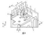
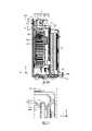
圖4繪示依據一些實施例,依圖2之視角,擴充匣之局部放大示意圖。FIG. 4 is a partially enlarged schematic view of the expansion box from the perspective of FIG. 2 , according to some embodiments.

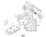
圖5繪示圖4之擴充匣之分解示意圖。FIG. 5 is an exploded schematic view of the expansion box of FIG. 4 .

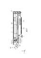
圖6繪示圖4中A-A位置之剖面示意圖,卡接件自動卡掣扣接部。FIG. 6 is a schematic cross-sectional view of the position A-A in FIG. 4 , and the engaging element automatically engages the engaging portion.

圖7繪示圖4中A-A位置之剖面示意圖,卡接件脫離扣接部。FIG. 7 is a schematic cross-sectional view of the position A-A in FIG. 4 , and the engaging element is disengaged from the engaging portion.

圖8繪示圖2中標示8之視角,擴充匣之局部放大示意圖。FIG. 8 is a partially enlarged schematic view of the expansion box from the viewing angle marked 8 in FIG. 2 .

圖9繪示依據一些實施例,擴充匣之俯視示意圖,顯示夾持件位於插卡區的狀態。FIG. 9 is a schematic top view of the expansion box according to some embodiments, showing the state where the clip is located in the card insertion area.

圖10繪示圖9中標示10之中心線框之放大示意圖,顯示卡接件脫離扣接部的狀態。FIG. 10 is an enlarged schematic view of the center line frame marked 10 in FIG. 9 , showing a state in which the engaging element is disengaged from the engaging portion.

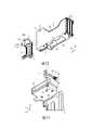
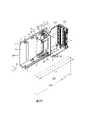
圖11繪示依據一些實施例,擴充匣與擴充模組之外觀示意圖,顯示夾持件滑移出插卡區,不同長度之擴充模組未安裝插卡區的狀態。FIG. 11 is a schematic diagram of the appearance of the expansion box and the expansion module according to some embodiments, showing the state in which the clamping member slides out of the card insertion area and the expansion modules of different lengths are not installed in the card insertion area.

圖12繪示依據一些實施例,擴充匣與擴充模組之外觀示意圖,顯示夾持件滑移出插卡區,供擴充模組安裝於插卡區的狀態。FIG. 12 is a schematic diagram of the appearance of the expansion box and the expansion module according to some embodiments, showing a state in which the clamping member slides out of the card insertion area for the expansion module to be installed in the card insertion area.

圖13繪示圖12狀態之俯視示意圖。FIG. 13 is a schematic top view of the state of FIG. 12 .

圖14繪示依據一些實施例,擴充匣與擴充模組之外觀示意圖,顯示夾持件位於插卡區,夾持件覆蓋於擴充模組側邊的狀態,卡接件自動卡掣扣接部。FIG. 14 is a schematic diagram of the appearance of the expansion box and the expansion module according to some embodiments, showing the state where the clip is located in the card insertion area, the clip covers the side of the expansion module, and the clip automatically locks the buckle portion .

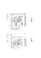
圖15繪示圖14狀態之俯視示意圖。FIG. 15 is a schematic top view of the state of FIG. 14 .

圖16繪示圖15中標示16之中心線框之放大示意圖,顯示卡接件導引至扣接部的狀態。FIG. 16 is an enlarged schematic view of the center line frame marked 16 in FIG. 15 , showing a state in which the clip is guided to the buckle portion.

圖17繪示圖15中標示16之中心線框之放大示意圖,顯示卡接件卡掣扣接部的狀態。FIG. 17 is an enlarged schematic view of the center line frame marked 16 in FIG. 15, showing the latch of the card connectorThe state of the clasp.

圖18繪示圖16之放大示意圖,顯示卡接件導引至扣接部的狀態,為卡接件與扣接部的另一種導引結構。FIG. 18 is an enlarged schematic view of FIG. 16 , showing a state where the clip is guided to the buckle portion, which is another guiding structure of the clip and the buckle portion.

圖19繪示圖17之放大示意圖,顯示卡接件卡掣扣接部的狀態,為卡接件與扣接部的另一種導引結構。FIG. 19 is an enlarged schematic view of FIG. 17 , showing the state of the clipping part of the clip, which is another guiding structure of the clip and the clip.

圖20繪示圖14遠離導軌部視角之側視示意圖,顯示限位件抵靠擴充模組的狀態。FIG. 20 is a schematic side view of FIG. 14 from a viewing angle away from the guide rail portion, showing a state in which the limiting member abuts against the expansion module.

圖21繪示圖20中標示21之中心線框之放大示意圖,顯示限位件的凹部夾持在擴充模組側端的狀態。FIG. 21 is an enlarged schematic view of the center line frame marked 21 in FIG. 20 , showing a state in which the concave portion of the limiting member is clamped at the side end of the expansion module.

圖22繪示依據一些實施例,擴充匣之分解示意圖,為卡接件與扣接部的另一種對接結構。FIG. 22 is an exploded schematic view of the expansion box according to some embodiments, which is another docking structure of the clip and the buckle.

圖23繪示依據一些實施例,擴充匣之分解示意圖,為卡接件的另一種對接結構。FIG. 23 is an exploded schematic view of the expansion box according to some embodiments, which is another docking structure of the clip.

圖24繪示依據一些實施例,擴充匣與擴充模組之外觀示意圖,顯示夾持件位於另一種插卡區的狀態,夾持件覆蓋於二點鏈線表示之擴充模組側邊。FIG. 24 is a schematic diagram of the appearance of the expansion box and the expansion module according to some embodiments, showing a state in which the clip is located in another card insertion area, and the clip covers the side of the expansion module indicated by the two-dot chain line.

請參閱圖1,圖1為具有擴充匣200之機箱100之外觀示意圖。在一些實施例中,網路設備採用機架式的結構,例如交換機、路由器或硬體防火牆。機箱100包括殼體101,殼體101內安裝一個或多個的擴充匣200(圖1為示意機箱100內安裝一個擴充匣200,亦可設置有多個擴充匣200),擴充匣200可在機箱100內任何位置安裝,擴充匣200內安裝擴充模組400。Please refer to FIG. 1 . FIG. 1 is a schematic diagram of the appearance of thechassis 100 having theexpansion box 200 . In some embodiments, the network equipment is in a rack-mounted configuration, such as switches, routers, or hardware firewalls. Thechassis 100 includes acasing 101, and one ormore expansion boxes 200 are installed in the casing 101 (FIG. 1 shows that oneexpansion box 200 is installed in thechassis 100, and a plurality ofexpansion boxes 200 can also be installed). Theexpansion boxes 200 can be installed in Installation anywhere in thechassis 100,expansion box 200Anexpansion module 400 is installed inside.

在一些實施例中,擴充模組400可以是但不限於擴充卡,例如高速序列電腦匯流排(PCI Express,Peripheral Component Interconnect Express,PCIe Card)。在一些實施例中,擴充模組400可為其他設備,例如硬碟。另外,擴充卡可為多張(如二張、三張或四張等)或為一張。In some embodiments, theexpansion module 400 may be, but is not limited to, an expansion card, such as a high-speed serial computer bus (PCI Express, Peripheral Component Interconnect Express, PCIe Card). In some embodiments, theexpansion module 400 may be other devices, such as hard disks. In addition, the expansion card can be multiple (such as two, three or four, etc.) or one.

在一些實施例中,擴充匣200可適用不同長度的擴充模組400安裝使用,例如圖11所示之實線表示具有第一長度L1的擴充模組400(長卡)使用,為FHFL(Full Height Full Length)為全高度、全長度的PCIe卡,或者是例如圖11所示之二點鏈線(假想線)表示具有第二長度L2的擴充模組400(長卡)使用,為FHFL為全高度、全長度的PCIe卡。兩種擴充模組400的長度不同,第一長度L1大於第二長度L2。在一些實施例中,可適用於例如圖24所示二點鏈線表示之具有短長度的擴充模組400(短卡)使用,為FHHL(Full Height Half Length)為全高度、半長度的PCIe卡,非以此為限。在一些實施例中,亦可使用HHHL半高度、半長度的PCIe卡。In some embodiments, theexpansion box 200 is suitable for installation and use ofexpansion modules 400 of different lengths. For example, the solid line shown in FIG. 11 indicates that the expansion module 400 (long card) with the first length L1 is used, which is FHFL (Full Height Full Length) is a full-height, full-length PCIe card, or for example, the two-dot chain line (imaginary line) shown in Figure 11 indicates that the expansion module 400 (long card) with the second length L2 is used, and the FHFL is Full-height, full-length PCIe card. The lengths of the twoexpansion modules 400 are different, and the first length L1 is greater than the second length L2. In some embodiments, it can be applied to the expansion module 400 (short card) with a short length as indicated by the two-dot chain line shown in FIG. 24 , which is PCIe with FHHL (Full Height Half Length) being full height and half length. card, not limited to this. In some embodiments, HHHL half-height, half-length PCIe cards may also be used.

請同時參考圖2及圖3,圖2為擴充匣200之外觀示意圖,圖3為擴充匣200之分解示意圖。在一些實施例中,擴充匣200包括托架1、夾持件2及卡接件3。Please refer to FIG. 2 and FIG. 3 at the same time. FIG. 2 is a schematic view of the appearance of theexpansion box 200 , and FIG. 3 is an exploded view of theexpansion box 200 . In some embodiments, theexpansion box 200 includes abracket 1 , aclip 2 and aclip 3 .

托架1包括第一滑移部11、扣接部12及插卡區10,插卡區10包含導軌部102,導軌部102供擴充模組400以第三軸X方向滑設於插卡區10。第一滑移部11與導軌部102分別設於插卡區10之兩側,亦可設置於托架1之兩側,但不以此為限。扣接部12設於插卡區10且遠離導軌部102之一側。Thebracket 1 includes a first slidingportion 11 , abuckle portion 12 and acard insertion area 10 . Thecard insertion area 10 includes aguide rail portion 102 , and theguide rail portion 102 is used for theexpansion module 400 to be slidably arranged in the card insertion area along the third axis X direction. 10. The first slidingportion 11 and theguide rail portion 102 are respectively disposed on both sides of thecard insertion area 10,placed on both sides of thebracket 1, but not limited to this. Thebuckle portion 12 is disposed on a side of thecard insertion area 10 away from theguide rail portion 102 .

夾持件2滑設於第一滑移部11。The clampingmember 2 is slidably arranged on the first slidingportion 11 .

卡接件3設於夾持件2,卡接件3適於卡掣該扣接部12。The clampingpart 3 is arranged on the clampingpart 2 , and the clampingpart 3 is suitable for clamping thebuckle part 12 .

在一些實施例中,夾持件2適於沿第一滑移部11位移於(以沿第一軸Z位移)第一位置P1及第二位置P2之間(如圖13所示第一位置P1,如圖15所示第二位置P2)。在夾持件2位於第一位置P1時,夾持件2遠離導軌部102且卡接件3分離於扣接部12。在夾持件2位於第二位置P2時,夾持件2接近導軌部102,卡接件3卡掣於扣接部12。In some embodiments, the clampingmember 2 is adapted to be displaced along the first sliding portion 11 (to be displaced along the first axis Z) between the first position P1 and the second position P2 (the first position shown in FIG. 13 ) P1, the second position P2 as shown in Figure 15). When the clampingmember 2 is located at the first position P1 , the clampingmember 2 is away from theguide rail portion 102 and the engagingmember 3 is separated from the engagingportion 12 . When the clampingmember 2 is located at the second position P2 , the clampingmember 2 is close to theguide rail portion 102 , and the clampingmember 3 is clamped to the clampingmember 12 .

當夾持件2移動於第一位置P1而滑移出插卡區10時(如圖11所示,意即夾持件2遠離導軌部102),擴充模組400可安裝托架1之插卡區10(如圖12所示)。當夾持件2沿第一軸Z由第一位置P1移動於第二位置P2時,夾持件2滑移入插卡區10(意即夾持件2接近導軌部102),夾持件2覆蓋擴充模組400一側且覆蓋在擴充模組400的至少一部分(如圖14、圖15所示的擴充模組400遠離導軌部102之一側被托架1與夾持件2包夾),防止擴充模組400被震動時掉落或脫離至托架1外部。When the holdingmember 2 moves to the first position P1 and slides out of the card insertion area 10 (as shown in FIG. 11 , which means the holdingmember 2 is away from the guide rail portion 102 ), theexpansion module 400 can be installed with the socket of thebracket 1 . Card area 10 (shown in Figure 12). When the clampingmember 2 moves from the first position P1 to the second position P2 along the first axis Z, the clampingmember 2 slides into the card insertion area 10 (that is, the clampingmember 2 is close to the guide rail portion 102 ), and the clampingmember 2 slides into thecard insertion area 10 . 2. Covering one side of theexpansion module 400 and covering at least a part of the expansion module 400 (as shown in FIG. 14 and FIG. 15 , the side of theexpansion module 400 away from theguide rail portion 102 is sandwiched by thebracket 1 and the clampingmember 2 ; ) to prevent theexpansion module 400 from being dropped or detached from the outside of thebracket 1 when it is shaken.

在一些實施例中,夾持件2限位在托架1之一側邊且包夾擴充模組400之一側(如圖14所示)。在夾持件2移動於第一位置P1時,夾持件2沿第一滑移部11滑移至托架1外部(如圖12、圖13所示),供長卡之擴充模組400沿導軌部102安裝在插卡區10。在夾持件2移動於第二位置P2時,夾持件2滑移至托架1內部且接近導軌部102(如圖14、圖15所示),覆蓋擴充模組400一側且覆蓋在擴充模組400的至少一部分,以支撐擴充模組400。In some embodiments, the clampingmember 2 is limited to one side of thebracket 1 and sandwiches one side of the expansion module 400 (as shown in FIG. 14 ). When the clampingmember 2 moves to the first position P1, the clampingmember 2 slides along the first slidingportion 11 to the outside of the bracket 1 (as shown in FIG. 12 and FIG. 13 ) for theexpansion module 400 of the long card. It is installed in thecard insertion area 10 along theguide rail portion 102 . When the clampingmember 2 moves to the second position P2, the clampingmember 2 slides into thebracket 1 and approaches the guide rail portion 102 (as shown in FIG. 14 and FIG. 15 ), covering the side of theexpansion module 400 and covering the side of theexpansion module 400 . at least a portion of theexpansion module 400,to support theexpansion module 400 .

在一些實施例中,夾持件2限位在托架1內部包夾擴充模組400,供短卡之擴充模組400(如圖24所示)使用。在夾持件2移動於第一位置P1時(圖未示,例如圖24所示之夾持件2在第一位置P1之一點鏈線指引處),夾持件2朝遠離導軌部102的方向移動至第一位置P1至托架1內最遠離導軌部102處,可供擴充模組400沿導軌部102安裝在插卡區10。在夾持件2移動於第二位置P2時,夾持件2沿第一軸Z朝向導軌部102滑移至第二位置P2(P2之實線指引處),覆蓋擴充模組400的一側。在一些實施例中,卡接件3及扣接部12之一設有復位結構9。當夾持件2朝第一位置P1移動時,復位結構9使卡接件3適於使卡接件3離開扣接部12。In some embodiments, the clampingmember 2 is limited within thebracket 1 to sandwich theexpansion module 400 for use by theexpansion module 400 of the short card (as shown in FIG. 24 ). When the clampingmember 2 is moved to the first position P1 (not shown in the figure, for example, the clampingmember 2 shown in FIG. 24 is at a point-chain line at the first position P1 ), the clampingmember 2 moves away from theguide rail portion 102 The direction moves to the first position P1 to the position farthest from theguide rail portion 102 in thebracket 1 , so that theexpansion module 400 can be installed in thecard insertion area 10 along theguide rail portion 102 . When the clampingmember 2 moves to the second position P2, the clampingmember 2 slides toward theguide rail portion 102 along the first axis Z to the second position P2 (the point indicated by the solid line of P2), covering one side of theexpansion module 400 . In some embodiments, one of theclip 3 and thebuckle portion 12 is provided with areset structure 9 . When the clampingmember 2 moves toward the first position P1 , thereset structure 9 makes the clampingmember 3 suitable for the clampingmember 3 to leave thebuckle portion 12 .

在一些實施例中,復位結構9使卡接件3離開扣接部12的方式:可為卡接件3具有彈性適於脫離扣接部12,或者是,可為扣接部12具有彈性而彈出並脫離卡接件3,卡接件3與扣接部12的詳細結構容後陳述。In some embodiments, thereset structure 9 can make theclip 3 leave the clip part 12 : theclip part 3 can be elastic and suitable for disengaging from theclip part 12 , or theclip part 12 can be elastic and Theclip 3 is ejected and disengaged. The detailed structure of theclip 3 and theclip 12 will be described later.

在一些實施例中,由於卡接件3位於夾持件2上,當夾持件2沿第一軸Z由第一位置P1移動於第二位置P2的過程中,夾持件2移動的同時會同步帶動卡接件3沿第一軸Z位移。當卡接件3移動至對應位於扣接部12的位置時,卡接件3可相對托架1沿第二軸Y自動卡掣於扣接部12。反之,當夾持件2沿第一軸Z由第二位置P2移動於第一位置P1的過程中,夾持件2移動的同時會同步帶動卡接件3沿第一軸Z位移。當卡接件3移動至脫離扣接部12時,卡接件3可相對托架1沿第二軸Y自動脫離或被動脫離於扣接部12。In some embodiments, since the clampingmember 3 is located on the clampingmember 2, when the clampingmember 2 moves from the first position P1 to the second position P2 along the first axis Z, the clampingmember 2 moves at the same time It will synchronously drive theclip 3 to move along the first axis Z. When the engagingmember 3 moves to a position corresponding to the engagingportion 12 , the engagingmember 3 can be automatically engaged with the engagingportion 12 along the second axis Y relative to thebracket 1 . Conversely, when the clampingmember 2 moves from the second position P2 to the first position P1 along the first axis Z, the clampingmember 2 moves and simultaneously drives the clampingmember 3 to displace along the first axis Z. When theclip 3 moves to thedisengagement part 12, theclip 3 can be automatically disengaged from thebracket 1 along the second axis YOr passively disengage from thebuckle portion 12 .

在一些實施例中,所謂的復位結構9使卡接件3離開扣接部12,可為自動脫離方式,為使用者未扳動卡接件3,卡接件3隨夾持件2移動過程中,自動脫離於扣接部12的方式。在一些實施例中,所謂的復位結構9使卡接件3離開扣接部12,可為被動脫離方式,為使用者扳動卡接件3,將卡接件3脫離於扣接部12的方式。In some embodiments, the so-calledreset structure 9 enables theclip 3 to leave theclip portion 12 , which can be an automatic disengagement method, because the user does not pull theclip 3 , and theclip 3 moves along with theclamp 2 . , it is automatically disengaged from thebuckle portion 12 . In some embodiments, the so-calledreset structure 9 enables theclip 3 to leave theclip part 12 , which can be a passive disengagement method, in which the user pulls theclip part 3 to disengage theclip part 3 from theclip part 12 . Way.

請再參考圖2及圖3,托架1具有底板1a及側板1b,底板1a與側板1b連接,且具有一角度關係。導軌部102設於側板1b之一側並與底板1a連接,扣接部12設於側板1b遠離導軌部102之另一側。第一滑移部11設於底板1a遠離導軌部102之一側且沿第一軸Z設置,扣接部12與第一滑移部11具有一角度關係,更詳細地說,扣接部12與第一滑移部11於第二軸Y方向與第三軸X方向上有一角度關係,但非以此為限。在一些實施例中,扣接部12與第一滑移部11亦可皆設於托架1同一軸向方向,例如皆設於第三軸X方向。Please refer to FIG. 2 and FIG. 3 again, thebracket 1 has a bottom plate 1a and aside plate 1b, and the bottom plate 1a is connected with theside plate 1b and has an angular relationship. Theguide rail portion 102 is disposed on one side of theside plate 1b and is connected to the bottom plate 1a, and thebuckle portion 12 is disposed on the other side of theside plate 1b away from theguide rail portion 102 . The first slidingportion 11 is disposed on a side of the bottom plate 1a away from theguide rail portion 102 and is disposed along the first axis Z. Thebuckle portion 12 and the first slidingportion 11 have an angular relationship. More specifically, thebuckle portion 12 There is an angular relationship with the first slidingportion 11 in the direction of the second axis Y and the direction of the third axis X, but not limited thereto. In some embodiments, thebuckle portion 12 and the first slidingportion 11 may also be disposed in the same axial direction of thebracket 1 , for example, in the third axis X direction.

請再參考圖2及圖3,在一些實施例中,夾持件2之一側與第一滑移部11對接,夾持件2的卡接件3對接於托架1的扣接部12,供夾持件2二側對接於托架1後可平穩的滑移第一位置P1及第二位置P2之間。Please refer to FIG. 2 and FIG. 3 again. In some embodiments, one side of the clampingmember 2 is abutted with the first slidingportion 11 , and the engagingmember 3 of the clampingmember 2 is abutted with the engagingportion 12 of thebracket 1 . , the two sides of the clampingmember 2 can smoothly slide between the first position P1 and the second position P2 after docking with thebracket 1 .

請再參考圖2及圖3,在一些實施例中,托架1設有第二滑移部15,第二滑移部15設於側板1b遠離導軌部102之一側並沿第一軸Z設置,由於側板1b及底板1a有一角度關係,故第二滑移部15與第一滑移部11亦有一角度關係。更詳細地說,第一滑移部11與第二滑移部15於第一軸Z方向平行,在第三軸X方向與第二軸Y方向有一角度關係,但非以此為限。在一些實施例中,第二滑移部15與第一滑移部11亦可皆設於托架1同一軸向方向,例如皆設於第三軸X方向。Please refer to FIG. 2 and FIG. 3 again, in some embodiments, thebracket 1 is provided with a second slidingportion 15 , and the second slidingportion 15 is provided on a side of theside plate 1 b away from theguide rail portion 102 and along the first axis Z Because theside plate 1b and the bottom plate 1a have an angular relationship, the second slidingportion 15 and the first slidingportion 11 also have an angular relationship. In more detail, the first slidingpart 11 and the second slidingpart 15 are in the firstOne axis Z direction is parallel, and there is an angular relationship between the third axis X direction and the second axis Y direction, but not limited thereto. In some embodiments, the second slidingportion 15 and the first slidingportion 11 may also be arranged in the same axial direction of thebracket 1 , for example, both are arranged in the X direction of the third axis.

請再參考圖2及圖3,在一些實施例中,夾持件2包括第三滑移部26及第四滑移部27,第三滑移部26及第四滑移部27分別用以對接於托架1,第三滑移部26及第四滑移部27具有一角度關係,更詳細地說,第三滑移部26與第四滑移部27於第一軸Z方向平行,在第三軸X方向與第二軸Y方向有一個角度關係,但非以此為限。第一滑移部11及第二滑移部15分別與夾持件2對接,第三滑移部26及第四滑移部27分別與托架1對接,使夾持件2對接於托架1後可平穩的滑移第一位置P1及第二位置P2之間。在一些實施例中,第三滑移部26與第四滑移部27分別對接於托架1之側板1b與底板1a,更詳細地說,第三滑移部26與第二滑移部15對接,而第一滑移部11與第四滑移部27在側板1b上於第一軸Z方向平行,在第三軸X方向與第二軸Y方向有一角度關係。Please refer to FIG. 2 and FIG. 3 again. In some embodiments, the clampingmember 2 includes a third slidingportion 26 and a fourth slidingportion 27 , and the third slidingportion 26 and the fourth slidingportion 27 are respectively used for The third slidingportion 26 and the fourth slidingportion 27 are in an angular relationship with respect to thebracket 1. More specifically, the third slidingportion 26 and the fourth slidingportion 27 are parallel to the first axis Z direction, There is an angular relationship between the X direction of the third axis and the Y direction of the second axis, but not limited thereto. The first slidingportion 11 and the second slidingportion 15 are respectively butted with the clampingmember 2 , and the third slidingportion 26 and the fourth slidingportion 27 are respectively butted with thebracket 1 , so that the clampingmember 2 is butted to the bracket After 1, it can smoothly slide between the first position P1 and the second position P2. In some embodiments, the third slidingportion 26 and the fourth slidingportion 27 are respectively connected to theside plate 1b and the bottom plate 1a of thebracket 1 , more specifically, the third slidingportion 26 and the second slidingportion 15 The first slidingpart 11 and the fourth slidingpart 27 are parallel to the first axis Z direction on theside plate 1b, and there is an angular relationship between the third axis X direction and the second axis Y direction.

請再參考圖2及圖3,在一些實施例中,第一滑移部11包含有第一長槽11以及第一鎖接件11(例如鉚釘或螺絲,以下以第一長槽11以及第一鎖接件11為例說明,並給予與第一滑移部11相同之標號),第一鎖接件11穿入第一長槽11且鎖接於夾持件2。當夾持件2相對於托架1移動於第一位置P1或第二位置P2時,第一鎖接件11分別抵止於第一長槽11之二側。如圖12所示,第一鎖接件11位於第一長槽11的遠離導軌部102之一側時,夾持件2相對於托架1移動於第一位置P1。如圖14所示,第一鎖接件11位於第一長槽11朝向導軌部102之另一側時,夾持件2相對於托架1移動於第二位置P2。Please refer to FIG. 2 and FIG. 3 again. In some embodiments, the first slidingportion 11 includes a firstlong slot 11 and a first locking member 11 (such as a rivet or screw, hereinafter referred to as the firstlong slot 11 and the first locking member 11 ). A lockingmember 11 is illustrated as an example, and is given the same number as the first sliding portion 11 ). Thefirst locking member 11 penetrates into the firstlong slot 11 and is locked to the clampingmember 2 . When the clampingmember 2 moves to the first position P1 or the second position P2 relative to thebracket 1 , the first lockingmember 11 abuts against two sides of the firstlong slot 11 respectively. As shown in FIG. 12 , when the first lockingmember 11 is located on a side of the firstlong groove 11 away from theguide rail portion 102 , the clampingmember 2 moves to the first position P1 relative to thebracket 1 . As shown in FIG. 14 , when the first lockingmember 11 is located on the other side of the firstlong groove 11 facing theguide rail portion 102 , the clampingmember2 is moved to the second position P2 relative to thecarriage 1 .

請再參考圖2及圖3,在一些實施例中,第三滑移部26包含有第三長槽26以及第三鎖接件26(例如鉚釘或螺絲,以下以第三長槽26以及第三鎖接件26為例說明,並給予與第三滑移部26相同之標號),第三鎖接件26穿入第三長槽26且鎖接於托架1。當夾持件2相對於托架1移動於第一位置P1或第二位置P2時,第三鎖接件26分別抵止於第三長槽26之二側。如圖8所示,第三鎖接件26位於第三長槽26朝向導軌部102之一側時,夾持件2相對於托架1移動於第二位置P2,當如圖8所示,夾持件2相對於托架1移動於第一位置P1時,第三鎖接件26位於第三長槽26遠離導軌部102之另一側。Referring to FIGS. 2 and 3 again, in some embodiments, the third slidingportion 26 includes a thirdlong groove 26 and a third locking member 26 (such as a rivet or a screw, hereinafter referred to as the thirdlong groove 26 and the third locking member 26 ). The threelocking members 26 are illustrated as an example, and are given the same reference numerals as the third sliding portion 26 ). Thethird locking members 26 penetrate into the thirdlong groove 26 and are locked to thebracket 1 . When the clampingmember 2 moves to the first position P1 or the second position P2 relative to thebracket 1 , thethird locking members 26 abut against two sides of the thirdlong groove 26 respectively. As shown in FIG. 8 , when thethird locking member 26 is located on the side of the thirdlong groove 26 facing theguide rail portion 102 , the clampingmember 2 moves to the second position P2 relative to thebracket 1 . As shown in FIG. 8 , When the clampingmember 2 moves to the first position P1 relative to thebracket 1 , thethird locking member 26 is located on the other side of the thirdlong groove 26 away from theguide rail portion 102 .

請再參考圖2及圖3,在一些實施例中,第四滑移部27包含有第四長槽27以及第四鎖接件27(例如鉚釘或螺絲,以下以第四長槽27以及第四鎖接件27為例說明,並給予與第四滑移部27相同之標號),第四鎖接件27穿入第四長槽27且鎖接於托架1。當夾持件2相對於托架1移動於第一位置P1或第二位置P2時,第四鎖接件27分別抵止於第四長槽27之二側。如圖12所示第四鎖接件27位於第四長槽27朝向導軌部102之一側時,夾持件2相對於托架1移動於第一位置P1。如圖14所示第四鎖接件27位於第四長槽27遠離導軌部102之另一側時,夾持件2相對於托架1移動於第二位置P2。Please refer to FIG. 2 and FIG. 3 again, in some embodiments, the fourth slidingportion 27 includes a fourthlong slot 27 and a fourth locking member 27 (such as a rivet or a screw, hereinafter referred to as the fourthlong slot 27 and the fourth locking member 27 ). The fourlocking members 27 are illustrated as an example, and are given the same reference numerals as the fourth sliding portion 27 ). Thefourth locking members 27 penetrate into the fourthlong slot 27 and are locked to thebracket 1 . When the clampingmember 2 moves to the first position P1 or the second position P2 relative to thebracket 1 , the fourth lockingmember 27 abuts against two sides of the fourthlong groove 27 respectively. As shown in FIG. 12 , when the fourth lockingmember 27 is located on the side of the fourthlong groove 27 facing theguide rail portion 102 , the clampingmember 2 moves to the first position P1 relative to thebracket 1 . As shown in FIG. 14 , when the fourth lockingmember 27 is located on the other side of the fourthlong groove 27 away from theguide rail portion 102 , the clampingmember 2 moves to the second position P2 relative to thebracket 1 .

請再參考圖2及圖3,在一些實施例中,第二滑移部15包含反折部15及溝槽15(以下以反折部15及溝槽15為例說明,並給予與第二滑移部15相同之標號),反折部15自側板1b一側朝向底板1a轉折,溝槽15位於反折部15與側板1b之間,夾持件2另一側側端25插入於溝槽15內限位。當夾持件2相對於托架1移動於第一位置P1或第二位置P2時,側端25在溝槽15中滑進或滑出。Please refer to FIG. 2 and FIG. 3 again, in some embodiments, the second slidingportion 15 includes a foldedportion 15 and a groove 15 (in the following, the foldedportion 15 and thegroove 15 are used as an example for description, and the second The slidingportion 15 has the same reference numeral), the reversingportion 15 is turned from theside plate 1b side toward the bottom plate 1a, and the grooveThegroove 15 is located between the foldedportion 15 and theside plate 1b, and the other side end 25 of the clampingmember 2 is inserted into thegroove 15 to limit the position. When theclamp 2 is moved relative to thebracket 1 in the first position P1 or the second position P2 , theside end 25 slides in or out in thegroove 15 .

請同時參考圖4至圖7,圖4依圖2之視角,擴充匣200之局部放大示意圖,圖5繪示圖4之擴充匣200之分解示意圖,圖6繪示圖4中A-A位置之剖面示意圖,卡接件3自動卡掣扣接部12,圖7繪示圖4中A-A位置之剖面示意圖,卡接件3脫離扣接部12。在一些實施例中,卡接件3可沿第二軸Y移動,如圖6所示卡接件3在夾持件2上方向朝向第二滑移部15移動並卡掣於扣接部12。如圖7所示卡接件3在夾持件2上方向遠離第二滑移部15移動並脫離扣接部12。在一些實施例中,卡接件3藉由彈性復位功能而自動卡掣於扣接部12。Please refer to FIG. 4 to FIG. 7 at the same time. FIG. 4 is a partial enlarged schematic view of theexpansion box 200 from the perspective of FIG. 2 , FIG. 5 is an exploded schematic view of theexpansion box 200 of FIG. 4 , and FIG. In the schematic diagram, theclip 3 automatically locks thebuckle portion 12 , and FIG. 7 shows a schematic cross-sectional view of the position A-A in FIG. 4 , theclip 3 is disengaged from thebuckle portion 12 . In some embodiments, theclip 3 can move along the second axis Y, and as shown in FIG. . As shown in FIG. 7 , the engagingmember 3 moves away from the second slidingportion 15 in the upper direction of the clampingmember 2 and disengages from the engagingportion 12 . In some embodiments, the latchingmember 3 is automatically latched to the latchingportion 12 by the elastic reset function.

請再參考圖4至圖7,在一些實施例中,卡接件3設有復位結構9而具有彈性作用,卡接件3包括第一止擋件31、第二止擋件32、卡接塊33(例如是但不限於塑膠材質)及復位件35。卡接塊33及復位件35位於第一止擋件31與第二止擋件32之間,卡接塊33抵接於第一止擋件31與第二止擋件32之間,而復位件35之二端分別抵接於卡接塊33與第二止擋件32。卡接塊33設有卡接部331,卡接部331與扣接部12卡合,使夾持件2與托架1固定,以支撐擴充模組400。Referring again to FIGS. 4 to 7 , in some embodiments, theclip 3 is provided with areset structure 9 to have an elastic effect, and theclip 3 includes afirst stopper 31 , asecond stopper 32 , a clip The block 33 (such as but not limited to plastic material) and thereset member 35 . The clampingblock 33 and thereset piece 35 are located between thefirst stopper 31 and thesecond stopper 32 , and the clampingblock 33 abuts between thefirst stopper 31 and thesecond stopper 32 to reset Two ends of thepiece 35 abut against the engagingblock 33 and thesecond stop piece 32 respectively. The engagingblock 33 is provided with a engagingportion 331 , and the engagingportion 331 is engaged with the engagingportion 12 to fix the clampingmember 2 and thebracket 1 to support theexpansion module 400 .

在一些實施例中,第一止擋件31設有穿孔311,卡接部331為凸柱,卡接部331套設於第一止擋件31之穿孔311。當卡接部331自動卡掣或脫離扣接部12,卡接部331被限位於穿孔311中而防止卡接塊33脫離第一止擋件31。第一止擋件31、第二止擋件32可透過鎖接、貼合、鉚接等方式定位在夾持件2上。In some embodiments, thefirst stopper 31 is provided with a throughhole 311 , the engagingportion 331 is a protruding column, and the engagingportion 331 is sleeved on the throughhole 311 of thefirst stopper 31 . When the engagingportion 331 is automatically engaged or disengaged from the engagingportion 12 , the engagingportion 331 is limited in the throughhole 311 to prevent theengaging block 33 from detaching from thefirst stopper 31 . Thefirst stopper 31 and thesecond stopper 32 can be locked, fitted,It is positioned on theholder 2 by means of riveting or the like.

在一些實施例中,扣接部12朝向卡接件3之側面設有扣孔121,當卡接件3於第二位置P2位置時,卡接部331與扣孔121卡合,使夾持件2與托架1固定,以支撐擴充模組400。在一些實施例中,卡接部331表面與扣接部12之扣孔121可為凹凸弧面相對接(圖未示,例如圖7所示扣孔121內側改為凹弧面,卡接部331表面改為凸弧面)。當施予一定的作用力將夾持件2向托架1外部推出時,卡接部331之凸弧面經由扣接部12之凹弧面導引,使卡接部331移動至扣孔121外部,達到卡接部331自動脫離扣接部12的作用,施予較小的作用力即可將卡接部331推出並脫離扣接部12。In some embodiments, thebuckle portion 12 is provided with abutton hole 121 on the side facing theclip member 3 . When theclip member 3 is at the second position P2 , theclip portion 331 is engaged with thebutton hole 121 to clamp Thecomponent 2 is fixed to thebracket 1 to support theexpansion module 400 . In some embodiments, the surface of the engagingportion 331 and thebutton hole 121 of the engagingportion 12 may be concave and convex arc surfaces (not shown, for example, the inner side of thebutton hole 121 shown in FIG. 7 is changed to a concave arc surface, and the engagingportion 331 surface is changed to convex arc). When a certain force is applied to push the clampingmember 2 out of thebracket 1 , the convex arc surface of the engagingportion 331 is guided by the concave arc surface of the engagingportion 12 , so that the engagingportion 331 moves to thebutton hole 121 Externally, the latchingportion 331 can be automatically disengaged from the latchingportion 12 , and the latchingportion 331 can be pushed out and disengaged from the latchingportion 12 by applying a small force.

請再參考圖4至圖7,在一些實施例中,卡接塊33設有扳動部332以及滑塊333,滑塊333自扳動部332側邊朝遠離復位件35的方向延伸,滑塊333抵靠於第二止擋件32,卡接塊33之側面334抵靠於第一止擋件31。如圖7所示,當使用者扳動扳動部332向遠離第二滑移部15方向解鎖時,卡接塊33藉由滑塊333抵靠於第二止擋件32上、以及卡接塊33之側面334抵靠於第一止擋件31上,提供卡接塊33在夾持件2上平穩滑動。Referring again to FIGS. 4 to 7 , in some embodiments, the engagingblock 33 is provided with a pullingportion 332 and a slidingblock 333 . Theblock 333 abuts against thesecond stopper 32 , and theside surface 334 of the engagingblock 33 abuts against thefirst stopper 31 . As shown in FIG. 7 , when the user pulls the pullingportion 332 to unlock the direction away from the second slidingportion 15 , the latchingblock 33 abuts against thesecond stopper 32 by theslider 333 and latches Theside surface 334 of theblock 33 abuts against thefirst stopper 31 , so that the engagingblock 33 can slide smoothly on theclamping element 2 .

在一些實施例中,卡接塊33朝向第二止擋件32之側邊設有凹槽335,即卡接塊33相反卡接部331之一側邊設有凹槽335,第二止擋件32相對於凹槽335設有突塊325,即第二止擋件32朝向卡接塊33設有突塊325,復位件35之一端限位於凹槽335,另一端套設於突塊325。在一些實施例中,復位件35為壓縮型彈簧,提供反彈力推動卡接塊33回到如圖6所示卡掣扣接部12的位置,使卡接件3自動卡掣扣接部12。In some embodiments, agroove 335 is formed on the side of the engagingblock 33 facing thesecond stopper 32 , that is, agroove 335 is formed on a side of the engagingblock 33 opposite to the engagingportion 331 . Thesecond stopper 32 is provided with aprotrusion 325 relative to thegroove 335 , that is, thesecond stopper 32 is provided with aprotrusion 325 toward the engagingblock 33 . . In some embodiments, thereset member 35 is a compression spring, which provides a rebound force to push the snap-onblock 33 back toAs shown in FIG. 6 , the position of the engagingportion 12 is locked, so that the engagingmember 3 automatically engages the engagingportion 12 .

請再參考圖4至圖7,在一些實施例中,夾持件2一側包括握持部21,握持部21朝遠離托架1之底板1a方向延伸,握持部21設置鄰近於卡接件3的位置處,供使用者同一手即可操作卡接件3與握持部21並移動夾持件2。Referring again to FIGS. 4 to 7 , in some embodiments, one side of the clampingmember 2 includes a grippingportion 21 , the grippingportion 21 extends away from the bottom plate 1 a of thebracket 1 , and the grippingportion 21 is disposed adjacent to the card At the position of theconnector 3 , the user can operate theclip 3 and the holdingpart 21 and move theclip 2 with the same hand.

請再參考圖4至圖7,在一些實施例中,欲將夾持件2由第二位置P2移動至第一位置P1,請參閱圖7側視觀之、圖9及圖10俯視觀之,使用者可先以大拇指(圖未示)沿第二軸Y方向推動扳動部332,扳動部332如圖7中箭頭方向移動,將卡接件3的卡接部331脫離扣接部12,此時卡接部331退離扣孔121,復位件35被壓縮,卡接件3被動脫離扣接部12。接著,以食指、中指、無名指及小拇指(圖未示)抵靠於握持部21,將握持部21沿第一軸Z方向朝遠離導軌部102方向推動,即可移動夾持件2朝第一位置P1移動。使用者以單手操作夾持件2與卡接件3移動,即可達成使夾持件2由第二位置P2(如圖15所示)移動至第一位置P1(如圖13所示),以進行後續安裝或移除擴充模組400的效果。Please refer to FIGS. 4 to 7 again. In some embodiments, to move the clampingmember 2 from the second position P2 to the first position P1, please refer to the side view of FIG. 7 , the top view of FIGS. 9 and 10 , the user can first push thetoggle portion 332 along the second axis Y direction with the thumb (not shown), and thetoggle portion 332 moves in the direction of the arrow as shown in FIG. 12 , at this time, the clampingpart 331 is withdrawn from thebutton hole 121 , thereset member 35 is compressed, and the clampingpart 3 is passively disengaged from thebuckle part 12 . Next, use the index finger, middle finger, ring finger and little finger (not shown) to abut against the grippingportion 21, and push the grippingportion 21 in the direction of the first axis Z to move away from theguide rail portion 102, so that the grippingmember 2 can be moved toward the The first position P1 moves. The user can move the clampingmember 2 and the clampingmember 3 with one hand to move the clampingmember 2 from the second position P2 (as shown in FIG. 15 ) to the first position P1 (as shown in FIG. 13 ) , for the effect of subsequent installation or removal of theexpansion module 400 .

請再參考圖4至圖7,在一些實施例中,扣接部12包括結合塊12(以下以結合塊12為例說明,並給予與扣接部12相同之標號),結合塊12硬度低於金屬(結合塊12例如是但不限於塑膠材質),便於卡接塊33與結合塊12的緩衝接觸。托架1設有一延伸部14,延伸部14為自反折部15朝向底板1a延伸出之板件,結合塊12定位於延伸部14,結合塊12可透過鎖接、貼合、鉚接等方式定位在延伸部14上,非以此為限。在一些實施例中,結合塊12可透過鎖接、貼合、鉚接等方式直接定位在托架1上(圖未示)。Referring again to FIGS. 4 to 7 , in some embodiments, thebuckle portion 12 includes a coupling block 12 (thecoupling block 12 is used as an example below, and the same reference numeral is given to the buckle portion 12 ), and thecoupling block 12 has a low hardness For metal (thecoupling block 12 is, for example, but not limited to, a plastic material), it is convenient for the clampingblock 33 to have a buffer contact with thecoupling block 12 . Thebracket 1 is provided with anextension portion 14 . Theextension portion 14 is a plate extending from the foldedportion 15 toward the bottom plate 1 a . Thecoupling block 12 is positioned on theextension portion 14 , and thecoupling block 12 can be locked, fitted, riveted, etc. Positioned on theextension portion 14, but not limited thereto. In some embodiments, thecombination block 12 can be directly positioned on the bracket by means of locking, fitting, riveting, etc.rack 1 (not shown).

請再參考圖3及圖8,圖8繪示圖2中標示8之視角,擴充匣200之局部放大示意圖。在一些實施例中,托架1包括一個或多個限位部18,限位部18為遠離於導軌部102之一側,限位部18具有自底板1a延伸彎折出之擋板18(以下以擋板18為例說明,並給予與限位部18相同之標號),限位部18將夾持件2限位於托架1,更詳細地說,限位部18設於托架1的底板1a並限位夾持件2的鄰近第四滑移部27的側邊。當夾持件移動至第二位置P2時,藉由朝向導軌部102之一擋板18夾制夾持件2,限制夾持件2在第一軸Z方向的自由度,藉由朝向導軌部102之另一擋板18止擋住夾持件2側邊,限位夾持件2在第二軸Y方向的自由度。Please refer to FIG. 3 and FIG. 8 again. FIG. 8 is a partially enlarged schematic view of theexpansion box 200 from the perspective indicated by 8 in FIG. 2 . In some embodiments, thebracket 1 includes one or more limitingportions 18 , the limitingportion 18 is a side away from theguide rail portion 102 , and the limitingportion 18 has a baffle plate 18 ( In the following, thebaffle 18 is used as an example for description, and the same reference numerals are given to the limiting portion 18 ). The limitingportion 18 limits the clampingmember 2 to thebracket 1 . More specifically, the limitingportion 18 is provided on thebracket 1 . the bottom plate 1a and limit the side edge of the clampingmember 2 adjacent to the fourth slidingpart 27 . When the clamping member moves to the second position P2, the clampingmember 2 is clamped by abaffle plate 18 facing theguide rail portion 102 to limit the degree of freedom of the clampingmember 2 in the direction of the first axis Z. Theother baffle 18 of 102 blocks the side of the clampingmember 2 to limit the degree of freedom of the clampingmember 2 in the direction of the second axis Y.

請參閱圖11至圖14,圖11為擴充匣200與擴充模組400之外觀示意圖,顯示夾持件2滑移出插卡區10,不同長度之擴充模組400未安裝插卡區10的狀態,圖12為擴充匣200與擴充模組400之外觀示意圖,顯示夾持件2滑移出插卡區10,供擴充模組400安裝於插卡區10的狀態,圖13繪示圖12狀態之俯視示意圖,圖14為擴充匣200與擴充模組400之外觀示意圖,顯示夾持件2位於插卡區10,夾持件2覆蓋於擴充模組400側邊的狀態,卡接件3自動卡掣扣接部12。在一些實施例中,擴充匣200內安裝有轉接板300,轉接板300上具有電性連接埠301。當擴充模組400如圖12所示沿第三軸X安裝於擴充匣200內時,擴充模組400的電性連接埠401電性連接於轉接板300上的電性連接埠301。在一些實施例中,擴充模組400側邊具有插接端402,用以供傳輸線(圖未示)插接。在一些實施例中,夾持件2具有一框口20(如圖14所示),擴充模組400側邊的插接端402暴露於框口20,以便於將傳輸線(圖未示)插接插接端402。Please refer to FIG. 11 to FIG. 14 . FIG. 11 is a schematic view of the external appearance of theexpansion box 200 and theexpansion module 400 , showing that theclip 2 slides out of thecard insertion area 10 , and theexpansion modules 400 of different lengths are not installed in thecard insertion area 10 . 12 is a schematic view of the external appearance of theexpansion box 200 and theexpansion module 400 , showing the state in which theholder 2 slides out of thecard insertion area 10 for theexpansion module 400 to be installed in thecard insertion area 10 , FIG. 13 shows FIG. 12 A schematic top view of the state, FIG. 14 is a schematic external view of theexpansion box 200 and theexpansion module 400 , showing the state where theclip 2 is located in thecard insertion area 10 , theclip 2 covers the side of theexpansion module 400 , and theclip 3 The snap-fit portion 12 is automatically snapped. In some embodiments, ariser board 300 is installed in theexpansion box 200 , and theriser board 300 has anelectrical connection port 301 . When theexpansion module 400 is installed in theexpansion box 200 along the third axis X as shown in FIG. 12 , theelectrical connection port 401 of theexpansion module 400 is electrically connected to theelectrical connection port 301 on theriser board 300 . In some embodiments, the side of theexpansion module 400 has aplug terminal 402 for plugging a transmission line (not shown). In some embodiments, theholder 2 has a frame opening 20 (as shown in FIG. 14 ), and theexpansion module 400Theplug terminals 402 on the side are exposed to theframe opening 20 , so that the transmission line (not shown) can be plugged into theplug terminals 402 .

請參閱圖16至圖17,圖16繪示圖15中標示16之中心線框之放大示意圖,顯示卡接件3導引至扣接部12的狀態,圖17繪示圖15中標示16之中心線框之放大示意圖,顯示卡接件3卡掣扣接部12的狀態。在一些實施例中,結合塊12設有扣孔121及導引面122,導引面122用以導引卡接部331至扣孔121內定位。當夾持件2由第一位置P1移動至第二位置P2的過程中(如圖15所示夾持件2朝向導軌部102移動),卡接件3的卡接部331接觸結合塊12上的導引面122,並導引至扣孔121的方向前進。請參閱圖17所示,持續將夾持件2向朝向導軌部102移動至第二位置P2後,卡接部331經由導引面122導引至扣孔121內定位。Please refer to FIGS. 16 to 17 . FIG. 16 is an enlarged schematic view of the center line frame marked 16 in FIG. 15 , showing the state in which theclip 3 is guided to thebuckle portion 12 , and FIG. 17 is a diagram of the frame marked 16 in FIG. 15 The enlarged schematic diagram of the center line frame, showing the state of the latchingpart 12 of the latchingelement 3 . In some embodiments, thecoupling block 12 is provided with abutton hole 121 and aguide surface 122 , and theguide surface 122 is used to guide the engagingportion 331 to be positioned in thebutton hole 121 . When the clampingmember 2 moves from the first position P1 to the second position P2 (as shown in FIG. 15 , the clampingmember 2 moves toward the guide rail portion 102 ), the clampingportion 331 of the clampingmember 3 contacts thecoupling block 12 Theguide surface 122 is guided to the direction of thebutton hole 121 to advance. Referring to FIG. 17 , after the clampingmember 2 is continuously moved toward theguide rail portion 102 to the second position P2 , the engagingportion 331 is guided into thebutton hole 121 via theguide surface 122 for positioning.

請參閱圖18及圖19,圖18繪示圖16之放大示意圖,顯示卡接件3導引至扣接部12的狀態,為卡接件3與扣接部12的另一種導引結構,圖19繪示圖17之放大示意圖,顯示卡接件3卡掣扣接部12的狀態,為卡接件3與扣接部12的另一種導引結構。在一些實施例中,卡接部331設有導引面336(如圖18所示),卡接部331以導引面336用以導引至扣孔121定位。當夾持件2由第一位置P1移動至第二位置P2過程中(如圖19所示夾持件2向朝向導軌部102移動),卡接件3的卡接部331上的導引面336接觸扣孔121外圍壁面,用以導引卡接部331至扣孔121的方向前進。請參閱圖19所示,持續將夾持件2向朝向導軌部102移動至第二位置P2後,卡接部331經由導引面336導引至扣孔121內定位。Please refer to FIG. 18 and FIG. 19 . FIG. 18 is an enlarged schematic view of FIG. 16 , showing the state where theclip 3 is guided to thebuckle portion 12 , which is another guiding structure of theclip 3 and thebuckle portion 12 . FIG. 19 is an enlarged schematic view of FIG. 17 , showing the state in which theclip 3 locks thebuckle portion 12 , which is another guiding structure of theclip 3 and thebuckle portion 12 . In some embodiments, the engagingportion 331 is provided with a guiding surface 336 (as shown in FIG. 18 ), and the engagingportion 331 is guided by the guidingsurface 336 to be positioned to thebutton hole 121 . When the clampingmember 2 moves from the first position P1 to the second position P2 (as shown in FIG. 19 , the clampingmember 2 moves toward the guide rail portion 102 ), the guide surface on the clampingportion 331 of the clampingmember 3 The 336 contacts the peripheral wall of thebutton hole 121 to guide the engagingportion 331 to advance in the direction of thebutton hole 121 . Referring to FIG. 19 , after the clampingmember 2 is continuously moved toward theguide rail portion 102 to the second position P2 , the engagingportion 331 is guided into thebutton hole 121 via theguide surface 336 for positioning.

請參閱圖20及圖21,圖20繪示圖14遠離導軌部102之側視示意圖,顯示限位件4抵靠擴充模組400的狀態,圖21繪示圖20中標示21之中心線框之放大示意圖,顯示限位件4的凹部41夾持在擴充模組400側端的狀態。在一些實施例中,擴充匣200更包括限位件4,限位件4設於夾持件2朝向托架1之底板1a之一面,即限位件4設於夾持件2朝向托架1之一側面,限位件4可為具有軟性材質之緩衝塊4(以下以緩衝塊4為例說明,並給予與限位件4相同之標號),緩衝塊4便於緩衝接觸擴充模組400,使擴充模組400限位於夾持件2與托架1之底板1a間,擴充模組400為全高度的PCIe卡,非以此為限。在一些實施例中,緩衝塊4與夾持件2可改變高度,便於緩衝接觸擴充模組400,擴充模組400為半高度的PCIe卡。緩衝塊4可透過鎖接、貼合、鉚接等方式定位在夾持件2內側。Please refer to FIG. 20 and FIG. 21 , FIG. 20 is a side view of FIG. 14 away from theguide rail portion 10221 is an enlarged schematic view of the center line frame marked 21 in FIG. 20 , showing that theconcave portion 41 of the limitingmember 4 is clamped at the side end of theexpansion module 400 state. In some embodiments, theexpansion box 200 further includes a limitingmember 4, and the limitingmember 4 is disposed on a surface of the bottom plate 1a of the clampingmember 2 facing thebracket 1, that is, the limitingmember 4 is disposed on the clampingmember 2 facing the bracket. On one side of 1, thelimiter 4 can be abuffer block 4 with a soft material (thebuffer block 4 is used as an example below, and the same number as thelimiter 4 is given), and thebuffer block 4 is convenient for buffering and contacting theexpansion module 400 , so that theexpansion module 400 is limited to be located between theholder 2 and the bottom plate 1a of thebracket 1, and theexpansion module 400 is a full-height PCIe card, not limited thereto. In some embodiments, the height of thebuffer block 4 and the clampingmember 2 can be changed to facilitate buffering and contact with theexpansion module 400 , and theexpansion module 400 is a half-height PCIe card. Thebuffer block 4 can be positioned on the inner side of the clampingmember 2 by means of locking, fitting, riveting or the like.

在一些實施例中,不同高度與不同寬度的擴充模組400可安裝在托架1內且供夾持件2夾持使用,例如圖11所示上方實線表示之第一種擴充模組400,其具有第一長度L1、第一寬度W1及第一高度H1,例如圖11所示上方虛線表示之第二種擴充模組400,其具有第二長度L2、第二寬度W2及第二高度H2。第一長度L1大於第二長度L2,第一寬度W1大於第二寬度W2,第一高度H1大於第二高度H2。如圖14所示為第一種擴充模組400安裝在托架1內且供夾持件2夾持使用。In some embodiments,expansion modules 400 with different heights and different widths can be installed in thebracket 1 and used for clamping by the clampingmember 2 , such as thefirst expansion module 400 indicated by the solid line above as shown in FIG. 11 . , which has a first length L1, a first width W1 and a first height H1, such as the second type ofexpansion module 400 indicated by the dotted line in FIG. 11, which has a second length L2, a second width W2 and a second height H2. The first length L1 is greater than the second length L2, the first width W1 is greater than the second width W2, and the first height H1 is greater than the second height H2. As shown in FIG. 14 , thefirst expansion module 400 is installed in thebracket 1 and used for clamping by the clampingmember 2 .

在一些實施例中,緩衝塊4側面具有交互排列之多個凹部41(截面外觀可為U型或V型等形狀)與多個凸部42,接觸於擴充模組400的側端403,多個凹部41與多個凸部42整體截面外觀為波浪狀。當夾持件2滑移至托架1內部時,緩衝塊4之一個凹部41對應夾持在擴充模組400的側端403。In some embodiments, the side surface of thebuffer block 4 has a plurality of concave parts 41 (the cross-sectional appearance can be U-shaped or V-shaped, etc.) and a plurality ofconvex parts 42 arranged alternately, which are in contact with theside end 403 of theexpansion module 400 . The overall cross-sectional appearance of eachconcave portion 41 and the plurality ofconvex portions 42 is wavy. When the clampingmember 2 slides into thebracket 1, aconcave portion 41 of thebuffer block 4 is correspondingly clamped in the expansion moldSide end 403 ofgroup 400 .

在一些實施例中,夾持件2內側的緩衝塊4可以多個凹部41的其中任何一個凹部41對應夾持在不同尺寸擴充模組400的側端403。例如是使用如圖11所示上方實線表示之第一種擴充模組400時,第一種擴充模組400的側端403卡掣於如圖20、圖21所示擴充模組400的側端403卡掣在上方緩衝塊4最遠離扣接部12的凹部41,非以此為限。例如是使用如圖11所示上方虛線表示之第二種擴充模組400時,如圖20所示,第二種擴充模組400的側端403亦可卡掣於限位件4的其中一凹部41,非以此為限。即緩衝塊4可因應不同尺寸的擴充模組400卡掣於擴充模組400的側端403以達到輔助定位與緩衝撞擊的效果。In some embodiments, thebuffer block 4 on the inner side of the clampingmember 2 can be correspondingly clamped on theside end 403 of theexpansion module 400 of different sizes by any one of the plurality ofconcave portions 41 . For example, when the first type ofexpansion module 400 shown in the upper solid line shown in FIG. 11 is used, theside end 403 of the first type ofexpansion module 400 is locked on the side of theexpansion module 400 as shown in FIG. 20 and FIG. 21 . Theend 403 is clamped on theconcave portion 41 of theupper buffer block 4 that is farthest from thebuckle portion 12 , but not limited to this. For example, when using the second type ofexpansion module 400 indicated by the upper dashed line in FIG. 11 , as shown in FIG. Theconcave portion 41 is not limited to this. That is, thebuffer block 4 can be clamped on theside end 403 of theexpansion module 400 according to theexpansion modules 400 of different sizes, so as to achieve the effect of assisting positioning and buffering impact.

上述多個凹部41與多個凸部42僅是舉例,在一些實施例中,限位件4側面具有至少一個凹部41即可,如圖20所示多個凹部41只剩下最遠離扣接部12(或任何位置)的一個凹部41,亦可有至少一個凹部41,非以此為限。The plurality ofconcave portions 41 and the plurality ofconvex portions 42 mentioned above are only examples. In some embodiments, at least oneconcave portion 41 may be provided on the side of the limitingmember 4. As shown in FIG. Oneconcave portion 41 of the portion 12 (or any position) may also have at least oneconcave portion 41, but not limited thereto.

請參閱圖22,圖22為擴充匣200之分解示意圖,為卡接件3與扣接部12的另一種對接結構。在一些實施例中,扣接部12設有扣孔121,扣孔121形成在托架1的側板1b上(如圖22所示但無圖3所示結合塊12的實施例)。Please refer to FIG. 22 . FIG. 22 is an exploded schematic view of theexpansion box 200 , which is another connection structure of theclip 3 and thebuckle portion 12 . In some embodiments, thebuckle portion 12 is provided with abutton hole 121 , and thebutton hole 121 is formed on theside plate 1 b of the bracket 1 (as shown in FIG. 22 but without thecombination block 12 shown in FIG. 3 ).

請參閱圖22,在一些實施例中,卡接件3設有彈片39(為另一種不同於圖5所示卡接塊33的實施例),彈片39一側設有突部391,突部391朝向托架1延伸設置,彈片39之突部391用以自動卡掣或自動脫離扣接部12之扣孔121(圖未示,例如圖16所示之脫離狀態、如圖17所示之卡掣狀態)。彈片39固設於夾持件2上且彈片39具有彈性,突部391的圓弧表面便於接觸扣孔121外圍壁面。當推動握持部21,使夾持件2由第一位置P1移動至第二位置P2時(如由圖13所示第一位置P1移動至如圖15所示第二位置P2時),彈片39之突部391自動卡掣於扣接部12之扣孔121。當扳動握持部21,使夾持件2由第二位置P2移動至第一位置P1時,使彈片39之突部391脫離於扣接部12。Referring to FIG. 22 , in some embodiments, theclip 3 is provided with an elastic piece 39 (an embodiment different from theclip block 33 shown in FIG. 5 ), and aprotrusion 391 is provided on one side of theelastic piece 39 . 391 is extended toward thebracket 1, and theprotrusion 391 of theelastic piece 39 is used for automatically locking or automatically disengaging thebutton hole 121 of the buckle portion 12 (not shown in the figure, such as the disengaged state shown in FIG. 16, as shown in FIG. 17).shown in the locked state). Theelastic piece 39 is fixed on the clampingmember 2 and has elasticity, and the arc surface of the protrudingportion 391 is convenient for contacting the peripheral wall surface of thebutton hole 121 . When the grippingportion 21 is pushed to move the clampingmember 2 from the first position P1 to the second position P2 (for example, from the first position P1 shown in FIG. 13 to the second position P2 shown in FIG. 15 ), the elastic piece The protrudingportion 391 of 39 is automatically clamped to thebutton hole 121 of thebuckle portion 12 . When the grippingportion 21 is pulled to move the clampingmember 2 from the second position P2 to the first position P1 , the protrudingportion 391 of theelastic piece 39 is disengaged from the engagingportion 12 .

請參閱圖23,圖23為擴充匣200之分解示意圖,為卡接件3的另一種對接結構。在一些實施例中,卡接件3包括第一止擋件31及復位件38(為另一種不同於圖5所示卡接塊33的實施例),復位件38內具有彈簧,復位件38一側設有卡接部381,復位件38之卡接部381穿設於第一止擋件31(圖未示,如圖23所示將復位件38一側結合在第一止擋件31的之穿孔311外圍)。卡接部381穿設於第一止擋件31之穿孔311,卡接部381卡掣或脫離扣接部12(圖未示,如圖13所示為脫離狀態、如圖15所示為卡掣狀態)。可經由彈簧的抵持,使卡接部381自動卡掣於扣接部12(圖未示),並可拉動復位件38,帶動卡接部381脫離扣接部12(圖未示)。Please refer to FIG. 23 . FIG. 23 is an exploded schematic view of theexpansion box 200 , which is another docking structure of theclip 3 . In some embodiments, theclip 3 includes afirst stop member 31 and a reset member 38 (an embodiment different from theclip block 33 shown in FIG. 5 ). Thereset member 38 has a spring inside, and thereset member 38 One side is provided with a latchingportion 381, and the latchingportion 381 of thereset member 38 passes through the first stopper 31 (not shown in the figure, as shown in FIG. the periphery of the perforation 311). The engagingportion 381 passes through the throughhole 311 of thefirst stopper 31 , and the engagingportion 381 engages or disengages the engaging portion 12 (not shown, as shown in FIG. switch status). The latchingportion 381 can be automatically clamped to the latching portion 12 (not shown) by the spring's resistance, and thereset member 38 can be pulled to drive the latchingportion 381 to disengage from the latching portion 12 (not shown).

請參閱圖24,圖24為擴充匣200與擴充模組400之外觀示意圖,顯示夾持件2位於另一種插卡區10的狀態,夾持件2覆蓋於二點鏈線表示之擴充模組400側邊。在一些實施例中,托架1包括多個扣接部12(例如二個、三個或四個等扣接部12),多個扣接部12可等距分布,卡接件3適於選擇性卡掣於多個扣接部12之一,使夾持件2限位在托架1的不同位置而覆蓋不同長度之擴充模組400使用。Please refer to FIG. 24 . FIG. 24 is a schematic view of the external appearance of theexpansion box 200 and theexpansion module 400 , showing the state where theholder 2 is located in anothercard insertion area 10 , and theholder 2 covers the expansion module indicated by the two-dot chain line 400 sides. In some embodiments, thebracket 1 includes a plurality of buckle parts 12 (for example, two, three or four equal buckle parts 12 ). Selectively clamped on one of the plurality ofbuckle portions 12 , so that the clampingmember 2 is limited to different positions of thebracket 1 to cover theexpansion modules 400 of different lengths.

例如圖24所示,托架1包括三個扣接部12運用為例,當卡接件3卡掣於托架1上最接近導軌部102的第一扣接部12時,夾持件2位在最接近導軌部102的一側,夾持件2限位在托架1內部並包夾具有第三長度L3之擴充模組400,第三長度L3之擴充模組400長度小於如圖11所示之第一長度L1之擴充模組400長度或第二長度L2之擴充模組400長度。在一些實施例中,若卡接件3卡掣於托架1上最遠離導軌部102的第二扣接部12,夾持件2位在遠離導軌部102的一側,夾持件2限位在托架1內部並可包夾長卡之擴充模組400(圖未示,例如圖11所示具有第一長度L1之擴充模組400或具有第二長度L2之擴充模組400放入圖24之托架1內被包夾)。在一些實施例中,若卡接件3卡掣於托架1上的第三扣接部12,第三扣接部12位於第一扣接部12與第二扣接部12之間,夾持件2位在遠離導軌部102的一側,夾持件2限位在托架1內部並包夾具有第四長度L4之擴充模組400(圖未示,例如圖24所示之一點鏈線表示之擴充模組400放入托架1內被包夾)。其中,第四長度L4之擴充模組400長度小於如圖11所示之第一長度L1之擴充模組400長度或第二長度L2之擴充模組400長度,且第四長度L4之擴充模組400大於第三長度L3之擴充模組400。因此,以托架1上設置不同位置之多個扣接部12(可依實際需求在托架1上任意位置設置扣接部12),可讓卡接件3選擇性卡掣多個扣接部12之一,即以單一種擴充匣200安裝各種擴充模組400之一後,以同一個夾持件2移動不同位置來覆蓋不同長度之擴充模組400使用。For example, as shown in FIG. 24 , thebracket 1 includes threebuckle parts 12 for example. When theclip part 3 is engaged with thefirst buckle part 12 on thebracket 1 that is closest to theguide rail part 102 , theclamp part 2 Located on the side closest to theguide rail portion 102 , the clampingmember 2 is limited inside thebracket 1 and sandwiches theexpansion module 400 with the third length L3 , and the length of theexpansion module 400 with the third length L3 is smaller than that shown in FIG. 11 . The length of theexpansion module 400 of the first length L1 or the length of theexpansion module 400 of the second length L2 is shown. In some embodiments, if the latchingmember 3 is latched on thesecond latching portion 12 on thebracket 1 that is farthest from theguide rail portion 102, the holdingmember 2 is located on the side away from theguide rail portion 102, and the holdingmember 2 is limited to The expansion module 400 (not shown in the figure, for example, theexpansion module 400 with the first length L1 or theexpansion module 400 with the second length L2 shown in FIG. Thebracket 1 in Figure 24 is sandwiched). In some embodiments, if the engagingmember 3 is engaged with the third engagingportion 12 on thebracket 1, the third engagingportion 12 is located between the first engagingportion 12 and the second engagingportion 12, and the clip Theholder 2 is located on the side away from theguide rail portion 102 , and theholder 2 is limited inside thebracket 1 and sandwiches the expansion module 400 (not shown in the figure, such as a point chain shown in FIG. 24 ) with the fourth length L4 Theexpansion module 400 indicated by the line is placed in thebracket 1 and is sandwiched). The length of theexpansion module 400 of the fourth length L4 is smaller than the length of theexpansion module 400 of the first length L1 or the length of theexpansion module 400 of the second length L2 as shown in FIG. 11 , and the expansion module of thefourth length L4 400 is greater than theexpansion module 400 of the third length L3. Therefore, thebracket 1 is provided with a plurality ofbuckle parts 12 at different positions (thebuckle parts 12 can be arranged at any position on thebracket 1 according to actual needs), so that theclip element 3 can selectively lock a plurality of buckle parts One of theparts 12 , that is, after installing one of thevarious expansion modules 400 with asingle expansion box 200 , thesame clamping member 2 is moved to different positions to cover theexpansion modules 400 of different lengths for use.

綜上,依據一些實施例,托架適用於不同長度之擴充模組安裝,夾持件滑移在托架側邊且覆蓋擴充模組,在擴充模組因震動落摔測試、運送、人為或自然因素而被震動時,夾持件可以避免擴充模組鬆脫或掉落。其次,依據一些實施例,夾持件的握持部與卡接件為鄰近設置,供單手即可操作卡接件脫離托架,且推動握持部將夾持件滑移、脫離擴充模組。另外,依據一些實施例,夾持件以滑動方式組裝在托架側邊,托架側邊僅需提供夾持件可滑動的空間即可,佔用空間少。此外,依據一些實施例,擴充模組側邊插接端外露在夾持件形成的框口內部,方便傳輸線電性連接插接端。To sum up, according to some embodiments, the bracket is suitable for the installation of expansion modules of different lengths, and the clamping member slides on the side of the bracket and covers the expansion module, and the expansion module falls due to vibration.The clamp can prevent the expansion module from loosening or falling when it is shaken by human or natural factors during testing, transportation, and human or natural factors. Secondly, according to some embodiments, the gripping portion of the clamping member and the engaging member are disposed adjacent to each other, so that the engaging member can be detached from the bracket by one-handed operation, and the gripping portion can be pushed to slide the gripping member out of the expansion mold. Group. In addition, according to some embodiments, the clamping member is assembled on the side of the bracket in a sliding manner, and the side of the bracket only needs to provide a space for the clamping member to slide, which occupies less space. In addition, according to some embodiments, the side plug end of the expansion module is exposed inside the frame opening formed by the clamping member, so as to facilitate the electrical connection of the transmission line to the plug end.

200:擴充匣 300:轉接板 301:電性連接埠 400:擴充模組 402:插接端 1:托架 1b:側板 11:第一滑移部,第一長槽,第一鎖接件 12:扣接部,結合塊 122:導引面 15:第二滑移部,反折部,溝槽 2:夾持件 20:框口 21:握持部 25:側端 27:第四滑移部,第四長槽,第四鎖接件 3:卡接件 31:第一止擋件 32:第二止擋件 33:卡接塊 35:復位件 Z:第一軸 Y:第二軸 X:第三軸 P2:第二位置200: Expansion Box 300: Adapter board 301: Electrical connection port 400: Expansion Module 402: plug end 1:Bracket 1b: side panel 11: The first sliding part, the first long groove, the first locking piece 12: Buckle part, combined block 122: Guide surface 15: The second sliding part, the folded part, the groove 2: Clamps 20: Frame mouth 21: Grip 25: side end 27: The fourth sliding part, the fourth long slot, the fourth locking piece 3: Clips 31: First stopper 32: Second stopper 33: Snap block 35: reset piece Z: the first axis Y: the second axis X: the third axis P2: Second position

Claims (20)

Translated fromChinese
一種擴充匣,包括:一托架,包括一第一滑移部、一扣接部及一插卡區,該插卡區包含一導軌部,該導軌部與該第一滑移部分別設置於該插卡區之兩側,該扣接部設於該插卡區且遠離該導軌部之一側;一夾持件,滑設於該第一滑移部,該夾持件包括一握持部;以及一卡接件,設於該夾持件,該卡接件適於卡掣該扣接部以將該夾持件定位於該托架,該握持部鄰近於該卡接件。An expansion box, comprising: a bracket, including a first sliding part, a buckle part and a card insertion area, the card insertion area includes a guide rail part, the guide rail part and the first sliding part are respectively arranged on On both sides of the card insertion area, the buckle portion is disposed on the side of the card insertion area and away from the guide rail portion; a clamping member is slidably disposed on the first sliding portion, and the clamping member includes a gripping member. and a clipping part, which is arranged on the clipping part, the clipping part is suitable for clipping the clipping part to position the clipping part on the bracket, and the holding part is adjacent to the clipping part.如請求項1所述的擴充匣,其中該夾持件適於沿該第一滑移部位移於一第一位置及一第二位置之間,在該夾持件位於該第一位置時,該夾持件遠離該導軌部且該卡接件分離於該扣接部,在該夾持件位於該第二位置時,該夾持件接近該導軌部且該卡接件卡掣於該扣接部。The expansion box of claim 1, wherein the clamping member is adapted to move between a first position and a second position along the first sliding portion, and when the clamping member is located at the first position, The clamping part is far away from the guide rail part and the engaging part is separated from the buckling part; when the clamping part is located at the second position, the clamping part is close to the guide rail part and the clamping part is clamped to the clasp connection.如請求項2所述的擴充匣,其中該卡接件及該扣接部之一設有一復位結構,在該夾持件朝該第一位置移動時,該復位結構適於使該卡接件離開該扣接部。The expansion box as claimed in claim 2, wherein one of the latching element and the latching portion is provided with a reset structure, and when the clamping element moves toward the first position, the reset structure is suitable for enabling the latching element out of the buckle.如請求項3所述的擴充匣,其中該卡接件包括一第一止擋件、一第二止擋件、一卡接塊及一復位件,該卡接塊設置於該第一止擋件與該第二止擋件之間,該復位件設置於該卡接塊與該第二止擋件之間,該卡接塊之一側邊設有一卡接部,該卡接部套設於該第一止擋件且適於卡掣或脫離該扣接部。The expansion box as claimed in claim 3, wherein the latching element comprises a first stopper, a second stopper, a latching block and a reset element, and the latching block is disposed on the first stopper The reset piece is arranged between the clamping block and the second stopper, a side edge of the clamping block is provided with a clamping part, and the clamping part is sleeved on the first stopper and suitable for clamping or disengaging from the buckling portion.如請求項4所述的擴充匣,其中該卡接塊相反該卡接部之一側邊設有一凹槽,該第二止擋件朝向該卡接塊設有出一突塊,該復位件之一端限位於該凹槽,另一端套設於該突塊。The expansion box as claimed in claim 4, wherein a side of the engaging block opposite to the engaging portion is provided with a groove, the second stopper is provided with a protruding block toward the engaging block, and the reset element One end is limited to the groove, and the other end is sleeved on the protruding block.如請求項4所述的擴充匣,其中該扣接部包含一結合塊,該結合塊定位於該托架,該結合塊設有一扣孔及一導引面,該導引面適於導引該卡接部定位於該扣孔。The expansion box as claimed in claim 4, wherein the buckle portion comprises a combination block, the combination block is positioned on the bracket, the combination block is provided with a button hole and a guide surface, and the guide surface is suitable for guiding The engaging portion is positioned at the button hole.如請求項4所述的擴充匣,其中該扣接部設有一扣孔,該卡接部設有一導引面,該導引面適於導引該卡接部至該扣孔定位。The expansion box according to claim 4, wherein the buckle portion is provided with a buckle hole, and the buckle portion is provided with a guide surface, and the guide surface is suitable for guiding the buckle portion to the button hole for positioning.如請求項3所述的擴充匣,其中該卡接件包括一第一止擋件及一復位件,該復位件一側設有一卡接部,該復位件之該卡接部穿設於該第一止擋件,且適於卡掣或脫離該扣接部。The expansion box as claimed in claim 3, wherein the latching member comprises a first stopper and a restoring member, a latching portion is provided on one side of the restoring member, and the latching portion of the restoring member passes through the restoring member. The first stopper is suitable for clamping or disengaging the buckling portion.如請求項3所述的擴充匣,其中該卡接件包含一彈片,該彈片設有朝向該托架延伸之一突部,該突部適於自動卡掣或脫離該扣接部。The expansion box as claimed in claim 3, wherein the latching member comprises an elastic piece, and the elastic piece is provided with a protruding portion extending toward the bracket, and the protruding portion is suitable for automatically latching or disengaging the latching portion.如請求項1所述的擴充匣,其中該托架具有一底板及一側板,該底板與該側板連接且具有一角度關係,該扣接部設於該側板,該第一滑移部設於該底板,該扣接部與該第一滑移部具有一角度關係。The expansion box of claim 1, wherein the bracket has a bottom plate and a side plate, the bottom plate is connected to the side plate and has an angular relationship, the buckle portion is disposed on the side plate, and the first sliding portion is disposed on the side plate The bottom plate, the buckle portion and the first sliding portion have an angular relationship.如請求項10所述的擴充匣,其中該托架包括一第二滑移部,該第二滑移部設於該側板,該夾持件對接於該第二滑移部,該第二滑移部與該第一滑移部具有一角度關係。The expansion box as claimed in claim 10, wherein the bracket comprises a second sliding portion, the second sliding portion is disposed on the side plate, the clamping member is connected to the second sliding portion, and the second sliding portion The shifting portion has an angular relationship with the first sliding portion.如請求項11所述的擴充匣,其中該夾持件包括一第三滑移部及一第四滑移部,該第三滑移部與該第四滑移部具有一角度關係,該第三滑移部與該第四滑移部分別對接於該托架之該側板與該底板。The expansion box of claim 11, wherein the clamping member includes a third sliding portion and a fourth sliding portion, the third sliding portion and the fourth sliding portion have an angular relationship, and the first sliding portion has an angular relationship with the fourth sliding portion. The third sliding portion and the fourth sliding portion are respectively connected to the side plate and the bottom plate of the bracket.如請求項12所述的擴充匣,其中該第一滑移部包含一第一長槽以及一第一鎖接件,該第一鎖接件穿入該第一長槽且鎖接於該夾持件,該第三滑移部包含一第三長槽以及一第三鎖接件,該第三鎖接件穿入該第三長槽且鎖接於該托架,該第四滑移部包含一第四長槽以及一第四鎖接件,該第四鎖接件穿入該第四長槽且鎖接於該托架。The expansion box of claim 12, wherein the first sliding portion comprises a first long slot and a first locking piece, the first locking piece penetrates the first long slot and is locked to the clip a holder, the third sliding portion includes a third long slot and a third locking piece, the third locking piece penetrates the third long slot and is locked to the bracket, the fourth sliding portion A fourth long slot and a fourth locking piece are included. The fourth locking piece penetrates the fourth long slot and is locked to the bracket.如請求項12所述的擴充匣,其中該第二滑移部包含一反折部及一溝槽,該反折部自該側板一側轉折,該溝槽位於該反折部與該側板之間。The expansion box of claim 12, wherein the second sliding portion comprises a folded portion and a groove, the folded portion is turned from one side of the side plate, and the groove is located between the folded portion and the side plate between.如請求項1所述的擴充匣,其中該托架遠離於該導軌部之一側包括多個限位部,該些限位部適於限位該夾持件。The expansion box as claimed in claim 1, wherein a side of the bracket away from the guide rail portion includes a plurality of limiting portions, and the limiting portions are suitable for limiting the clamping member.如請求項1所述的擴充匣,更包括一限位件,設於該夾持件朝向該托架之一側面,該限位件側面具有一凹部。The expansion box as claimed in claim 1, further comprising a limiting member disposed on a side of the clamping member facing the bracket, and a side surface of the limiting member has a concave portion.如請求項1所述的擴充匣,更包括一限位件,該限位件設於該夾持件朝向該托架之一側面,該限位件側面具有交互排列之多個凹部與多個凸部。The expansion box as claimed in claim 1, further comprising a limiting member, the limiting member is disposed on a side of the clamping member facing the bracket, and the lateral side of the limiting member has a plurality of concave portions and a plurality of alternately arranged convex part.如請求項1所述的擴充匣,其中該卡接件包括一第一止擋件、一第二止擋件、一卡接塊及一復位件;該托架設有一底板及一側板,該底板與該側板具有一角度關係;該扣接部設於該側板,該第一滑移部設於該底板,該扣接部與該第一滑移部具有一角度關係;該卡接塊設於該第一止擋件與該第二止擋件之間該復位件抵持於該卡接塊與該第二止擋件之間;該卡接塊之一側邊設有一卡接部,該卡接部穿設於該第一止擋件之一穿孔且適於卡掣或脫離該扣接部;該卡接塊相反於該卡接部之一側邊設有一凹槽,該第二止擋件朝向該卡接塊突出一突塊,該復位件之一端限位於該凹槽,該復位件之另一端套設於該突塊;該夾持件適於沿該第一滑移部移動於一第一位置及一第二位置之間;該扣接部包含一結合塊,該托架設有一延伸部,該結合塊定位於該延伸部,該結合塊設有一導引面及一扣孔,該導引面適於導引該卡接部至該扣孔;該托架包括一第二滑移部,該第二滑移部與該夾持件對接,該第二滑移部位於該側板,該第二滑移部與該第一滑移部具有一角度關係;該夾持件包括一第三滑移部及一第四滑移部,該第三滑移部及該第四滑移部分別與該托架之該側板與該底板對接;該擴充匣更包括一限位件,該限位件位於該夾持件朝向該底板之一面,該限位件具有交互排列之多個凹部與多個凸部。The expansion box as claimed in claim 1, wherein the latching element comprises a first stopper, a second stopper, a latching block and a reset element; the bracket is provided with a bottom plate and a side plate, the bottom plate has an angular relationship with the side plate; the buckle part is arranged on the side plate, the first sliding part is arranged on the bottom plate, and the buckle part has an angular relationship with the first sliding part; the engaging block is arranged onBetween the first stopper and the second stopper, the reset piece abuts between the engagement block and the second stopper; a side edge of the engagement block is provided with a engagement portion, the The latching portion passes through a through hole of the first stopper and is suitable for latching or disengaging the latching portion; the latching block is provided with a groove opposite to a side of the latching portion, and the second stopper is provided with a groove. The blocking piece protrudes toward the engaging block, one end of the reset piece is limited to the groove, and the other end of the reset piece is sleeved on the protruding block; the clamping piece is suitable for moving along the first sliding portion between a first position and a second position; the buckle part includes a combination block, the bracket is provided with an extension part, the combination block is positioned on the extension part, the combination block is provided with a guide surface and a button hole , the guide surface is suitable for guiding the latching part to the button hole; the bracket includes a second sliding part, the second sliding part is butted with the clamping part, and the second sliding part is located in the The side plate, the second sliding part has an angular relationship with the first sliding part; the clamping part includes a third sliding part and a fourth sliding part, the third sliding part and the fourth sliding part The moving parts are respectively connected with the side plate of the bracket and the bottom plate; the expansion box further includes a limiting piece, the limiting piece is located on a side of the clamping piece facing the bottom plate, and the limiting piece has a plurality of alternately arranged A concave part and a plurality of convex parts.一種機箱,包括:一殼體;至少一擴充匣,該擴充匣設於該殼體內,該擴充匣包括一托架、一夾持件,該托架包括一第一滑移部、一扣接部及一插卡區,該插卡區包含一導軌部,該導軌部與該第一滑移部分別設置於該插卡區之兩側,該扣接部設於該插卡區遠離該導軌部之一側,該夾持件滑設於該第一滑移部,該夾持件包括一握持部;以及一卡接件,設於該夾持件,該卡接件適於卡掣該扣接部以將該夾持件定位於該托架,該握持部鄰近於該卡接件。A case, comprising: a shell; at least one expansion box, the expansion box is set in the shell, the expansion box includes a bracket, a clamping part, the bracket includes a first sliding part, a buckle a card insertion area, the card insertion area includes a guide rail part, the guide rail part and the first sliding part are respectively arranged on both sides of the card insertion area, and the buckle part is arranged in the card insertion area away from the guide rail On one side of the part, the clamping part is slidably arranged on the first sliding part, and the clamping part includes a holding part; andA clamping part is arranged on the clamping part, the clamping part is suitable for clamping the buckle part to position the clamping part on the bracket, and the holding part is adjacent to the clamping part.如請求項19所述的機箱,其中該至少一擴充匣的該夾持件適於沿該第一滑移部位移於一第一位置及一第二位置之間,在該夾持件位於該第一位置時,該夾持件遠離該導軌部且該卡接件分離於該扣接部,在該夾持件位於該第二位置時,該夾持件接近該導軌部且該卡接件卡掣於該扣接部。The chassis of claim 19, wherein the clamping member of the at least one expansion box is adapted to move between a first position and a second position along the first sliding portion, where the clamping member is located in the In the first position, the clamping part is far away from the guide rail part and the clipping part is separated from the buckle part; when the clipping part is in the second position, the clipping part is close to the guide rail part and the clipping part is The clip is locked on the buckle portion.
TW109143312A2020-12-012020-12-08Chassis and cage thereofTWI774151B (en)

Applications Claiming Priority (2)

Application NumberPriority DateFiling DateTitle
CN202011382736.12020-12-01
CN202011382736.1ACN114585201B (en)2020-12-012020-12-01Case and expansion box thereof

Publications (2)

Publication NumberPublication Date
TW202224525A TW202224525A (en)2022-06-16
TWI774151Btrue TWI774151B (en)2022-08-11

Family

ID=81752068

Family Applications (1)

Application NumberTitlePriority DateFiling Date
TW109143312ATWI774151B (en)2020-12-012020-12-08Chassis and cage thereof

Country Status (3)

CountryLink
US (1)US11622463B2 (en)
CN (1)CN114585201B (en)
TW (1)TWI774151B (en)

Cited By (1)

* Cited by examiner, † Cited by third party
Publication numberPriority datePublication dateAssigneeTitle
TWI815664B (en)*2022-09-162023-09-11英業達股份有限公司Multi-network card compatible double-layer rack

Families Citing this family (3)

* Cited by examiner, † Cited by third party
Publication numberPriority datePublication dateAssigneeTitle
CN117271420A (en)*2022-06-132023-12-22纬联电子科技(中山)有限公司Casing device for expansion card and server
TWI845099B (en)*2022-12-302024-06-11神雲科技股份有限公司Cage and electronic device
TWI880777B (en)*2024-06-122025-04-11英業達股份有限公司Expansion cage assembly and server device

Citations (2)

* Cited by examiner, † Cited by third party
Publication numberPriority datePublication dateAssigneeTitle
TWI553448B (en)*2014-12-102016-10-11英業達股份有限公司 Server and its rack
TWM579432U (en)*2018-12-032019-06-11緯創資通股份有限公司Chassis structure

Family Cites Families (13)

* Cited by examiner, † Cited by third party
Publication numberPriority datePublication dateAssigneeTitle
TW445021U (en)*1999-09-172001-07-01Hon Hai Prec Ind Co LtdMagnetic holding device
JP4220114B2 (en)*2000-09-182009-02-04株式会社東芝 Card support device and electronic device
TWM249070U (en)*2003-10-312004-11-01Hon Hai Prec Ind Co LtdMounting apparatus for storage device
CN2673041Y (en)*2003-11-292005-01-19鸿富锦精密工业(深圳)有限公司Data accessor fixer
US7806489B2 (en)*2005-08-052010-10-05Hewlett-Packard Development Company, L.P.Latch systems for a drive cage assembly
TWI331004B (en)*2007-01-182010-09-21Asustek Comp IncApparatus for fastening data-storage device
WO2009047838A1 (en)*2007-10-092009-04-16Fujitsu LimitedFastening structure and fastening method
CN201364580Y (en)*2009-01-192009-12-16但以诚科技股份有限公司Electronic card capable of being plugged with chip card
US9617757B2 (en)*2010-02-252017-04-11Sargent Manufacturing CompanyLocking device with configurable electrical connector key and internal circuit board for electronic door locks
CN102243516A (en)*2010-05-122011-11-16鸿富锦精密工业(深圳)有限公司Fixing device for information accessor
CN204257864U (en)*2014-12-252015-04-08纬创资通(中山)有限公司Interface card stuck-module
CN111857252B (en)*2019-04-242022-09-30纬联电子科技(中山)有限公司Mounting structure of expansion card
CN110267481B (en)*2019-06-212020-11-10华为技术有限公司Slide rail and rack

Patent Citations (2)

* Cited by examiner, † Cited by third party
Publication numberPriority datePublication dateAssigneeTitle
TWI553448B (en)*2014-12-102016-10-11英業達股份有限公司 Server and its rack
TWM579432U (en)*2018-12-032019-06-11緯創資通股份有限公司Chassis structure

Cited By (1)

* Cited by examiner, † Cited by third party
Publication numberPriority datePublication dateAssigneeTitle
TWI815664B (en)*2022-09-162023-09-11英業達股份有限公司Multi-network card compatible double-layer rack

Also Published As

Publication numberPublication date
CN114585201B (en)2024-09-17
US11622463B2 (en)2023-04-04
CN114585201A (en)2022-06-03
TW202224525A (en)2022-06-16
US20220174834A1 (en)2022-06-02

Similar Documents

PublicationPublication DateTitle
TWI774151B (en)Chassis and cage thereof
KR910007513Y1 (en) Pluggable Assemblies for Printed Circuit Cards
JP2000149539A (en)Apparatus and method for registering data memory module
JP2000156076A (en)Data storage module enclosure device
WO2017054281A1 (en)Cassette structure and electronic device
TW202030572A (en)Electronic device with external image capturing module
TWI780486B (en)Cage for add-on card and electronic device having the same
WO2021134657A1 (en)Optical module unlocking device, optical module, and optical communication device
CN111459238B (en) Chassis
US9060426B2 (en)Securing mechanism
TW201304311A (en)Card connector
CN108649359B (en)Card insertion device and electronic equipment
TWI669043B (en) Pull-up device
US20090165254A1 (en)Housing of foldable device
TWI557554B (en)Fixture for accommodating an electronic device during test
CN102024487B (en) Drawout box and drawout electronic device
CN218603083U (en)Fastening tool
TW200930247A (en)Locking and ejecting apparatus for data storage device and assembly with the same
CN102622059B (en)Interface card fixing device
CN209606913U (en) storage device
TWM484221U (en)Plug assembly
CN108667475B (en)Card insertion device and electronic equipment
TWM563719U (en)Pulling assistance device
CN110737312A (en)Fixing device and electronic equipment adopting same
TWM626213U (en)Shielding tool for data transmission hole

[8]ページ先頭

©2009-2025 Movatter.jp