TWI773416B - Ring-shaped gasket for sealingly joining opposed fluid conduit ports and method of forming a high purity fluid joint - Google Patents
Ring-shaped gasket for sealingly joining opposed fluid conduit ports and method of forming a high purity fluid jointDownload PDFInfo
- Publication number
- TWI773416B TWI773416BTW110124484ATW110124484ATWI773416BTW I773416 BTWI773416 BTW I773416BTW 110124484 ATW110124484 ATW 110124484ATW 110124484 ATW110124484 ATW 110124484ATW I773416 BTWI773416 BTW I773416B
- Authority
- TW
- Taiwan
- Prior art keywords
- gasket
- shaft end
- end surface
- stress concentration
- lip
- Prior art date
Links
Images


Classifications
- F—MECHANICAL ENGINEERING; LIGHTING; HEATING; WEAPONS; BLASTING
- F16—ENGINEERING ELEMENTS AND UNITS; GENERAL MEASURES FOR PRODUCING AND MAINTAINING EFFECTIVE FUNCTIONING OF MACHINES OR INSTALLATIONS; THERMAL INSULATION IN GENERAL
- F16J—PISTONS; CYLINDERS; SEALINGS
- F16J15/00—Sealings
- F16J15/16—Sealings between relatively-moving surfaces
- F16J15/32—Sealings between relatively-moving surfaces with elastic sealings, e.g. O-rings
- F16J15/3204—Sealings between relatively-moving surfaces with elastic sealings, e.g. O-rings with at least one lip
- F16J15/3232—Sealings between relatively-moving surfaces with elastic sealings, e.g. O-rings with at least one lip having two or more lips
- F16J15/3236—Sealings between relatively-moving surfaces with elastic sealings, e.g. O-rings with at least one lip having two or more lips with at least one lip for each surface, e.g. U-cup packings
- F—MECHANICAL ENGINEERING; LIGHTING; HEATING; WEAPONS; BLASTING
- F16—ENGINEERING ELEMENTS AND UNITS; GENERAL MEASURES FOR PRODUCING AND MAINTAINING EFFECTIVE FUNCTIONING OF MACHINES OR INSTALLATIONS; THERMAL INSULATION IN GENERAL
- F16J—PISTONS; CYLINDERS; SEALINGS
- F16J15/00—Sealings
- F16J15/02—Sealings between relatively-stationary surfaces
- F16J15/06—Sealings between relatively-stationary surfaces with solid packing compressed between sealing surfaces
- F16J15/08—Sealings between relatively-stationary surfaces with solid packing compressed between sealing surfaces with exclusively metal packing
- F16J15/0806—Sealings between relatively-stationary surfaces with solid packing compressed between sealing surfaces with exclusively metal packing characterised by material or surface treatment
- F—MECHANICAL ENGINEERING; LIGHTING; HEATING; WEAPONS; BLASTING
- F16—ENGINEERING ELEMENTS AND UNITS; GENERAL MEASURES FOR PRODUCING AND MAINTAINING EFFECTIVE FUNCTIONING OF MACHINES OR INSTALLATIONS; THERMAL INSULATION IN GENERAL
- F16J—PISTONS; CYLINDERS; SEALINGS
- F16J15/00—Sealings
- F16J15/02—Sealings between relatively-stationary surfaces
- F16J15/06—Sealings between relatively-stationary surfaces with solid packing compressed between sealing surfaces
- F16J15/08—Sealings between relatively-stationary surfaces with solid packing compressed between sealing surfaces with exclusively metal packing
- F16J15/0881—Sealings between relatively-stationary surfaces with solid packing compressed between sealing surfaces with exclusively metal packing the sealing effect being obtained by plastic deformation of the packing
- F—MECHANICAL ENGINEERING; LIGHTING; HEATING; WEAPONS; BLASTING
- F16—ENGINEERING ELEMENTS AND UNITS; GENERAL MEASURES FOR PRODUCING AND MAINTAINING EFFECTIVE FUNCTIONING OF MACHINES OR INSTALLATIONS; THERMAL INSULATION IN GENERAL
- F16J—PISTONS; CYLINDERS; SEALINGS
- F16J15/00—Sealings
- F16J15/02—Sealings between relatively-stationary surfaces
- F16J15/06—Sealings between relatively-stationary surfaces with solid packing compressed between sealing surfaces
- F16J15/08—Sealings between relatively-stationary surfaces with solid packing compressed between sealing surfaces with exclusively metal packing
- F16J15/0887—Sealings between relatively-stationary surfaces with solid packing compressed between sealing surfaces with exclusively metal packing the sealing effect being obtained by elastic deformation of the packing
Landscapes
- Engineering & Computer Science (AREA)
- General Engineering & Computer Science (AREA)
- Mechanical Engineering (AREA)
- Gasket Seals (AREA)
- Flanged Joints, Insulating Joints, And Other Joints (AREA)
- Joints With Pressure Members (AREA)
- Joints With Sleeves (AREA)
- Sealing Material Composition (AREA)
Abstract
Description
Translated fromChinese本發明係關於用於密封一流體通路之部分之間的接頭之可延展襯墊。The present invention relates to malleable gaskets for sealing joints between portions of a fluid passageway.
本發明之實施例係關於用於密封一流體通路之部分之間的接頭之可延展(主要地,金屬)襯墊。在流體輸送裝置之設計中熟知界面結構及相關聯襯墊之許多組合。此等結構包含凸緣、壓蓋、組件連接件及實現形成互連流體通路之一集合之多種裝置元件之機械總成之其他功能件。在生產精細化學品、石油產品、平板電子顯示器或半導體之工業設備中存在代表性流體輸送裝置且該等代表性流體輸送裝置可經歷真空或壓力或純度要求及其等之組合之要求。在半導體製造設備內意欲操縱程序材料之元件中之流體通路通常需要注意維持所輸送反應物之高純度且亦通常具有大大地小於(例如)石油化工裝置中使用之流體通路之一橫截面。在許多情況中,實踐者已發現:金屬襯墊提供優異效能,尤其關於程序流體或污染物通過該襯墊之擴散及對非所要洩漏之隨後阻抗,優於聚合物材料。一種已知類型之流體通路接頭使用一環形襯墊(最初在一徑向方向上係平坦的),其軸向地壓縮於包圍相對裝置元件之圓形導管開口之名義上一致形狀之環形突出部之間。該等環形突出部經軸向推動朝向彼此,致使產生一密封之該易延展金屬襯墊之永久塑性變形,該密封將抵抗甚至難以含有流體(諸如,氦)之洩漏。此等接頭之代表性實例可參見於頒予Carlson及Wheeler (作為Varian®Conflat®flange而被熟知)之美國專利第3,208,758號、頒予Callahan及Wennerstrom (作為Swagelok®VCR®fitting而被熟知)之美國專利第3,521,910號及頒予Harra及Nystrom之美國專利第4,303,251號。另一已知類型之流體通路接頭使用壓縮於包圍相對裝置元件之圓形導管開口之名義上一致形狀之環形突出部之間的預定橫截面輪廓之一環形襯墊。此等接頭之代表性實例可參見於頒予Leigh之美國專利第4,854,597號、頒予McGarvey之美國專利第5,505,464號及頒予Ohmi等人之美國專利第6,135,155號(W密封接頭類型之一早期版本)。Ohmi等人之專利額外地提供一單獨保持器構件用於在接頭裝配期間固持該襯墊且使該襯墊置於中心。其他單獨保持器結構亦可參見於兩者皆頒予Barber及Aldridge之美國專利第5,673,946號及美國專利第5,758,910號以及頒予Ohmi等人之美國專利第7,140,647號。又另一已知類型之流體通路接頭(作為C密封接頭類型而被熟知)使用壓縮於具有與該襯墊接觸之簡單平坦表面之相對裝置元件之間的複雜形狀之一環形金屬襯墊。最通常地,至少一個裝置元件之該面具有一圓形埋頭孔凹陷部分以接納該襯墊。此等接頭之代表性實例可參見於頒予Inagaki等人之美國專利第5,797,604號、兩者皆頒予Doyle之美國專利第6,357,760號及美國專利第6,688,608號以及頒予Spence及Felber之美國專利第6,409,180號。頒予Spence及Felber之該'180號專利額外地提供一單獨保持器構件用於在接頭裝配期間固持該襯墊且使該襯墊置於中心。其他單獨保持器結構亦可參見於頒予Kojima及Aoyama之美國專利第5,984,318號、頒予Doyle之美國專利第6,845,984號及頒予Whitlow等人之美國專利第6,945,539號。此外,頒予本發明發明者Kim Ngoc Vu等人之美國專利第5,992,463號及頒予Swensen等人之美國專利第5,730,448號展示:一適合厚度保持器可替代地提供一埋頭孔側壁之壓縮限制功能且允許一襯墊使用於簡單平坦相對面之間。高純度流體輸送組件及流體通路元件通常由316L型不鏽鋼或鎳合金(諸如,Hastelloy®C-22®)之一經真空精煉變體組成。此等金屬材料兩者僅可藉由機械加工而非熱處理而硬化且因此有被伴隨金屬襯墊之局域化力損壞之風險。亦已知由聚合物材料組成之高純度流體輸送組件且其等通常使用於控制某些液體流體之流動時(其中,具有金屬離子之潛在污染係一問題)。在許多聚合物裝置設計中,流體通路接頭亦使用具有一插入式襯墊之相對平坦表面(具有或不具有埋頭孔)。用於此等接頭之由聚合物材料組成之襯墊亦可受益於本發明中所描述之發明性設計。Embodiments of the invention relate to malleable (primarily metallic) gaskets for sealing joints between portions of a fluid passageway. Many combinations of interface structures and associated pads are well known in the design of fluid delivery devices. These structures include flanges, glands, component connectors, and other functions that implement the mechanical assembly of various device elements that form a collection of interconnected fluid pathways. Representative fluid delivery devices exist in industrial equipment producing fine chemicals, petroleum products, flat panel electronic displays, or semiconductors and such representative fluid delivery devices may experience vacuum or pressure or purity requirements and combinations thereof. Fluid passages in components within semiconductor fabrication equipment intended to handle process materials typically require care to maintain high purity of the reactants delivered and also typically have a cross-section that is substantially smaller than that of fluid passages used, for example, in petrochemical plants. In many cases, practitioners have found that metal gaskets provide superior performance, especially with respect to diffusion of process fluids or contaminants through the gasket and subsequent resistance to undesired leakage, over polymeric materials.One known type of fluid passage joint uses an annular gasket (originally flat in a radial direction) that is axially compressed against a nominally uniformly shaped annular projection surrounding the circular conduit opening of the opposing device element between. The annular projections are pushed axially towards each other causing permanent plastic deformation of the malleable metal gasket creating a seal that will resist even difficult leaks containing fluids such as helium. Representative examples of such fittings can be found in US Pat. No. 3,208,758 to Carlson and Wheeler (known as Varian® Conflat® flange), Callahan and Wennerstrom (known as Swagelok® VCR® fitting) US Patent No. 3,521,910 and US Patent No. 4,303,251 to Harra and Nystrom.Another known type of fluid pathway fitting uses an annular gasket compressed between a predetermined cross-sectional profile of annular projections of nominally uniform shape surrounding the circular conduit opening of the opposing device element. Representative examples of such joints can be found in US Patent No. 4,854,597 to Leigh, US Patent No. 5,505,464 to McGarvey, and US Patent No. 6,135,155 to Ohmi et al. (an earlier version of one type of sealing joint ). The Ohmi et al patent additionally provides a separate retainer member for holding and centering the pad during joint assembly. Other individual retainer structures can also be found in US Patent Nos. 5,673,946 and 5,758,910, both to Barber and Aldridge, and US Patent No. 7,140,647 to Ohmi et al.Yet another known type of fluid pathway fitting (known as the C-seal fitting type) uses an annular metal gasket of complex shape compressed between opposing device elements having simple flat surfaces in contact with the gasket. Most typically, the face of at least one device element has a circular countersunk recessed portion to receive the gasket. Representative examples of such linkers can be found in US Patent Nos. 5,797,604 to Inagaki et al., US Patent Nos. 6,357,760 and 6,688,608 both to Doyle and US Patent Nos. 6,688,608 to Spence and Felber No. 6,409,180. The '180 patent to Spence and Felber additionally provides a separate retainer member for holding and centering the pad during splice assembly. Other individual retainer structures can also be found in US Patent Nos. 5,984,318 to Kojima and Aoyama, US Patent Nos. 6,845,984 to Doyle and 6,945,539 to Whitlow et al. In addition, US Pat. No. 5,992,463 to Kim Ngoc Vu et al. and US Pat. No. 5,730,448 to Swensen et al. show that a suitable thickness retainer can alternatively provide a compression limiting function of a countersunk sidewall And allows a gasket to be used between simple flat opposing surfaces.High purity fluid delivery assemblies and fluid passage elements are typically composed of one of the vacuum refined variants of Type 316L stainless steel or nickel alloys such as Hastelloy® C-22®. Both of these metallic materials can only be hardened by machining, not heat treatment, and are therefore at risk of being damaged by the localized forces that accompany the metallic backing. High-purity fluid delivery components composed of polymeric materials are also known and are commonly used in controlling the flow of certain liquid fluids where potential contamination with metal ions is a problem. In many polymer device designs, the fluid path fittings also use relatively flat surfaces (with or without countersinks) with a plug-in gasket. Gaskets composed of polymeric materials for these joints may also benefit from the inventive designs described in this disclosure.
本發明之實施例係關於用於密封地結合相對流體導管端口之一環形襯墊。該等流體導管端口可對應於一流體輸送系統(諸如,一半導體氣體面板、一石油化學生產或分配系統,等等)之毗鄰流體導管端口。該襯墊具有一主體,該主體藉由產生一流體通路且界定一徑向內部表面之一孔貫穿且額外地具有一徑向外部表面、一第一軸端表面及一第二軸端表面。該第一軸端表面及該第二軸端表面之至少一者具有徑向地毗鄰於一襯墊密封區域之一應力集中特徵部,該襯墊密封區域經構造且經配置以與一對應流體導管端口之一表面接觸。在一項實施例中,該應力集中特徵部界定該襯墊密封區域中之一唇緣,該唇緣包含一保護脊及一密封表面。在接頭裝配之前,該密封區域唇緣以所期望方式軸向向外突出超過該對應軸端表面。在一實施例中,該應力集中特徵部包括位於該等軸端表面之一者或兩者中且毗鄰該一個或兩個對應襯墊密封區域之一凹槽。在另一實施例中,該應力集中凹槽底切一個或兩個密封區域。在一些實施例中,該應力集中凹槽具有底切一個或兩個密封區域之一V形狀,且在其他實施例中,該應力集中凹槽具有一U形狀,該U形狀具有底切一個或兩個密封區域之實質上平行邊。在又一實施例中,該應力集中特徵部包括突出進入該等軸端表面之一者或兩者中之盲孔之一規則配置。在另一實施例中,該等規則配置之應力集中盲孔底切一個或兩個密封區域唇緣。在另一實施例中,該等盲孔之該圓周相位關係可反相重合或插入。在又另一實施例中,一第一軸端表面具有包含底切一第一密封區域之盲孔之一規則配置之一應力集中特徵部且一第二軸端表面具有最初在一徑向方向上係平坦之一第二密封區域。在另一實施例中,一第一軸端表面具有包含底切一第一密封區域之一凹槽之一應力集中特徵部且一第二軸端表面具有最初在一徑向方向上係平坦之一第二密封區域。該凹槽可具有一V形狀或具有實質上平行邊之一U形狀。在任何實施例中,該等軸端表面之一者或兩者可具有毗鄰該襯墊徑向外部表面之一圓周區域,該圓周區域用作一止擋件以限制該可變形密封區域之壓縮。本文中所描述之多種實施例之環形襯墊可由一可延展材料形成。該可延展材料可包含:選自由一不鏽鋼合金、一鉻合金、一鎳合金、商業純鎳、一銅合金及商業純銅組成之群組之一單件式金屬材料;實質上等同於316型系列不鏽鋼合金之一單件式金屬材料;選自由聚丙烯(PP)、聚偏二氟乙烯(PVDF)、全氟烷氧基聚合物(PFA)、聚四氟乙烯(PTFE)、聚三氟氯乙烯(PCTFE)及聚醯亞胺組成之群組之一單件式聚合物材料;或者實質上等同於聚醯亞胺之一單件式聚合物材料。根據本文中所描述之多種態樣,提供一種形成一高純度流體接頭之方法,其中一襯墊(其開始作為具有一未變形襯墊密封表面之可延展材料之一閉合環圈,該未變形襯墊密封表面橫跨該襯墊環圈形狀之一近端內部軸而成角度)壓縮於相對流體輸送裝置元件之間,直至該襯墊密封表面之一部分實質上垂直於該襯墊環圈形狀之近端內部軸而彎曲為止。Embodiments of the present invention relate to an annular gasket for sealingly engaging opposing fluid conduit ports. The fluid conduit ports may correspond to adjacent fluid conduit ports of a fluid delivery system (such as a semiconductor gas panel, a petrochemical production or distribution system, etc.). The gasket has a body through a bore that creates a fluid passage and defines a radially inner surface and additionally has a radially outer surface, a first shaft end surface, and a second shaft end surface. At least one of the first shaft end surface and the second shaft end surface has a stress concentration feature radially adjacent to a gasket sealing region that is structured and configured to communicate with a corresponding fluid One of the catheter ports is in surface contact. In one embodiment, the stress concentration feature defines a lip in the gasket sealing region, the lip including a protective ridge and a sealing surface. Prior to fitting of the joint, the sealing area lip projects axially outwardly beyond the corresponding shaft end surface in the desired manner.In one embodiment, the stress concentration feature includes a groove in one or both of the isometric end surfaces adjacent to one of the one or both corresponding gasket sealing areas. In another embodiment, the stress concentration groove undercuts one or both sealing areas. In some embodiments, the stress concentration groove has a V shape that undercuts one or both of the sealing regions, and in other embodiments, the stress concentration groove has a U shape that undercuts one or both of the sealing regions. Substantially parallel sides of the two sealing regions.In yet another embodiment, the stress concentration feature includes a regular arrangement of blind holes protruding into one or both of the isometric end surfaces. In another embodiment, the regularly arranged stress concentration blind holes undercut one or both of the sealing area lips. In another embodiment, the circumferential phase relationship of the blind holes can be coincident or inserted in opposite phases.In yet another embodiment, a first shaft end surface has a regular arrangement of stress concentration features including blind holes that undercut a first sealing area and a second shaft end surface has initially a radial direction The upper tie flat is a second sealing area. In another embodiment, a first shaft end surface has a stress concentration feature including a groove undercutting a first sealing region and a second shaft end surface has an initially flat in a radial direction A second sealing area. The groove may have a V shape or a U shape with substantially parallel sides. In any embodiment, one or both of the shaft end surfaces may have a circumferential region adjacent to the radially outer surface of the gasket, the circumferential region serving as a stop to limit compression of the deformable sealing region .The annular gasket of various embodiments described herein may be formed from a malleable material. The malleable material may comprise: a one-piece metallic material selected from the group consisting of a stainless steel alloy, a chromium alloy, a nickel alloy, commercially pure nickel, a copper alloy, and commercially pure copper; substantially equivalent to the Type 316 series One-piece metal material of stainless steel alloy; selected from polypropylene (PP), polyvinylidene fluoride (PVDF), perfluoroalkoxy polymer (PFA), polytetrafluoroethylene (PTFE), polychlorotrifluoroethylene A one-piece polymeric material of the group consisting of ethylene (PCTFE) and polyimide; or a one-piece polymeric material substantially equivalent to polyimide.According to aspects described herein, there is provided a method of forming a high purity fluid joint in which a gasket (which begins as a closed loop of malleable material having an undeformed gasket sealing surface, the undeformed gasket) The gasket sealing surface is angled across a proximal inner axis of the gasket ring shape) compressed between opposing fluid delivery device elements until a portion of the gasket sealing surface is substantially perpendicular to the gasket ring shape The proximal inner shaft is bent until it is bent.
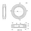
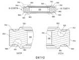
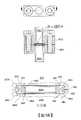
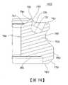
[相關申請案之交叉參考]本申請案依據35 U.S.C. § 119(e)主張在2014年4月17日申請之美國臨時申請案第61/980,823號之優先權,該案標題為「ULTRA-SEAL GASKET FOR JOINING HIGH PURITY FLUID PATHWAYS」,該美國臨時申請案以全文引用的方式併入本文中。本文中所討論之裝置及方法之實例不受限於下列描述中所闡述或圖式中所繪示之組件之構造及配置之細節應用。該等裝置及方法能夠具有其他實施例且能夠以多種方式實踐或實施。同樣地,本文中所使用之用語及術語係為描述之目的且不應視為限制性的。「包含」、「包括」或「具有」、「含有」、「涉及」及其等在本文中之變體之使用意謂涵蓋其後所列之項目及其等效物以及額外項目。使具有密封整體性之流體通路接頭足以在一分子級(例如,小於1×10e-9.std.cc/sec之氦洩漏速率)上最小化洩漏涉及特殊設計考量。在技術熟練設計者當中,已知:使用一金屬襯墊而使一接頭成功配合金屬流體輸送裝置元件大大地受益於與該等裝置元件接觸之該襯墊密封區域之塑性變形。當自具有相對大泊松比及較低降伏強度之襯墊材料(諸如,銅)改變至具有較小泊松比及較高降伏強度之襯墊材料(如不鏽鋼)時,適合變形變得更加難以達成。此外,可需要實質軸向力來達成一金屬襯墊中之任何軸向應變。一個設計方法涉及使一襯墊具有經軸向定向密封區域,該等區域具有實質上減小接觸區域以促進該襯墊之該等密封區域之塑性變形而無所要求軸向結合力之一有問題的大增加。更容易達成襯墊塑性變形之一有關及通常同時使用之技術係使該襯墊材料退火至一最大柔軟狀態中。另一已知設計挑戰係金屬之相對較高楊氏模數(彈性模數),其導致在彈性變形之後之相對小可逆金屬襯墊彈回且亦限制可在塑性變形發生之前賦予至一金屬襯墊之應變量。如材料力學之研究中所知,退火並未明顯影響襯墊之勁度(彈性模數)但將明顯地降低其降伏強度。該應變硬化(其在繼許多襯墊材料之初始降伏之後發生)對該襯墊之最終彈回性質而言可係一顯著貢獻者。又一設計挑戰係事實:缺乏充分塊體硬度之一襯墊隨時間可呈現冷流放鬆且藉此儘管最初係適合緊密的,但發展一洩漏。前述有問題的變形特性可使接頭軸向維度容限在大量生產情境中比所期望更重要且亦產生可描述為一襯墊內之剩餘擴張力不足以確保密封整體性之問題。此等挑戰之一設計解決方案自一環形部分之塊體選擇性地排除材料以產生誘發有意及有效應力集中之一襯墊橫截面輪廓。此應力集中致使當產生凈彈性軸向應變時需要較少軸向力且可能在該襯墊塊體之一些內部區域中產生應變硬化。所得可逆彈性軸向位移與軸向力之關係提供呈現大於其他可用襯墊之回彈之一襯墊且因此使用較少總所需裝置元件配合力而形成一更加可靠結合。可(例如)藉由切除部分(如在先前所引述的Doyle專利及Spence及Felber專利中) 或藉由使薄板存料形成為具有“C”形橫截面之一圓環(如在兩者皆頒予Swensen等人之美國專利第5,730,448號及美國專利第5,713,582號中所展示)而完成材料之排除,或可藉由實際上併入一環形彈簧(如Inagaki專利中)而獲得所要類似於彈簧之行為,以及其他製造技術。Doyle以及Spence及Felber之設計在一徑向方向上移除材料且因此受限於襯墊內部流體通路與外部環境之間之保證最小壁厚度之要求。就這一點而言,製造容限亦可具有相反結果。在許多先前引述之美國專利實例中,在接頭裝配之前存在不利地磨損一襯墊之軸向定向密封區域之相當大的風險且此損壞藉此使無洩漏之一接頭不可達成。藉由一單獨保持器而置於中心之襯墊提供流體通路導管端口與通過該襯墊之該中心通路之間之所期望對準一致性。在用於半導體製造製程之一些流體輸送裝置或器件內,存在同時使用多種類型之流體通路接頭之情境且因此期望允許相對襯墊密封區域上之襯墊密封表面之實體形狀之獨立裁剪及/或相對襯墊密封區域之機械行為之一襯墊結構。申請者之環形襯墊之一第一代表性實例100繪示於圖1A及圖1B中。襯墊主體150藉由界定包括一徑向內部表面156之一流體通路內孔155之一孔151貫穿,徑向內部表面156可便利地係實質上筆直的以減小耦合接頭之流體輸送裝置中之流體亂流。該襯墊主體之該外部徑向範圍藉由一徑向外部表面190界定,徑向外部表面190可具有一圓周凹槽192以容置一定位件(圖1A中未展示)用於定位襯墊100於一流體輸送組件總成(圖1A中亦未展示)中。該第一代表性襯墊實例可具有包含一應力集中特徵部120之一第一軸端表面110,應力集中特徵部120呈現為第一軸端表面110中之一凹槽。應力集中特徵部120自緊鄰預期襯墊密封區域之區域移除襯墊主體材料以藉此形成一唇緣130,唇緣130可在進行結合之前以期望方式軸向向外突出超過該第一軸端表面。唇緣130包含一軸向突出保護脊132及一緊鄰密封表面134。在該襯墊滑動穿過一粗糙表面之情況中,在正常工廠處置期間,保護脊132可被損壞但密封表面134將保持原樣。密封表面134係相對於襯墊內孔155軸且亦相對於第一軸端表面110之平面呈現一大致上恒定角度之一圓周區段,但針對一些襯墊材料可有利地具有一稍微凸狀。襯墊密封區域唇緣130可瞭解為類似自襯墊內孔155朝向徑向外部表面190向外張開之一截頭圓錐形殼體。密封表面134之該徑向範圍有利地大於先前設計之經減小接觸區域以便產生抵抗該襯墊與流體導管端口面之間之接觸之一更長徑向洩漏。當襯墊100藉由相對平坦裝置面之間之軸向壓縮被製成一密封流體通路接頭時,藉助於允許唇緣130彎曲之凹槽120,保護脊132將塑性地變形且密封表面134稍微徑向向外偏轉接觸該平坦裝置面,與進一步軸向壓縮相呼應。該第一代表性襯墊實例可具有包含一應力集中特徵部170之一第二軸端表面160,應力集中特徵部170呈現為第二軸端表面160中之一凹槽。應力集中特徵部170自緊鄰預期襯墊密封區域之區域移除襯墊主體材料以藉此形成一唇緣180,唇緣180可在進行結合之前以期望方式軸向向外突出超過該第二軸端表面。唇緣180包含一軸向突出保護脊182及一緊鄰密封表面184。在該襯墊滑動穿過一粗糙表面之情況中,在正常工廠處置期間,保護脊182可被損壞但密封表面184仍將保持原樣。密封表面184係相對於襯墊內孔155軸且亦相對於第二軸端表面160之平面呈現一大致上恒定角度之一圓周區段,但針對一些襯墊材料可有利地具有一稍微凸狀。密封表面184之該徑向範圍有利地大於先前設計之經減小接觸區域以便產生抵抗該襯墊與流體導管端口面之間之接觸之一更長徑向洩漏。當襯墊100藉由相對平坦裝置面之間之軸向壓縮被製成一密封流體通路接頭時,藉助於允許唇緣180彎曲之凹槽170,保護脊182將塑性地變形且密封表面184稍微徑向向外偏轉接觸該平坦裝置面,與進一步軸向壓縮相呼應。襯墊設計者可瞭解,軸端表面110、160可如何充當藉由接觸該等對應流體導管端口之該表面而防止襯墊唇緣130、180之過分壓縮之相對硬止擋件。在進行結合時,在襯墊壓縮製程期間,襯墊100內之非常小的組成及製造變化可致使一軸端表面110、160在其他軸端表面160、110之前接觸對應流體導管端口面。所提及之硬止擋件功能確保相對襯墊唇緣130、180兩者最終同樣地且完全地壓縮。亦應瞭解,流體通路內孔155之端區域157、158將較佳地具有小於軸端表面110、160之軸向範圍以防止當接頭完全配合時虛漏腔室形成於該流體通路內。設計者亦可理解,襯墊主體150內之不變中心材料之存在使第一軸端表面唇緣130之變形行為實質上獨立於第二軸端表面唇緣180之變形行為。申請者之環形襯墊之一第二代表性實例200繪示於圖2A及圖2B中且類似於該第一實例。襯墊主體250藉由界定包括一徑向內部表面256之一流體通路內孔255之一孔251貫穿,徑向內部表面256可便利地係實質上筆直的以減小耦合接頭之流體輸送裝置中之流體亂流。該襯墊主體之該外部徑向範圍藉由一徑向外部表面290界定,徑向外部表面290可具有一圓周凹槽292以容置一定位件(圖2A及圖2B中未展示)用於定位襯墊200於一流體輸送組件總成(亦未展示)中。該第二代表性襯墊實例可具有包含應力集中特徵部220、270之第一軸端表面210及第二軸端表面260,應力集中特徵部220、270呈現為軸端表面210、260中之凹槽。應力集中特徵部220、270自緊鄰兩個預期襯墊密封區域之區域移除襯墊主體材料以藉此形成唇緣230、280於軸端表面210、260上,該等唇緣可在進行結合之前以期望方式軸向向外突出超過對應軸端表面210、260。應力集中凹槽220、270具有最接近襯墊徑向內部表面256之內壁221、271,襯墊徑向內部表面256與各相關聯襯墊軸端表面210、260之平面形成一銳角藉此形成各襯墊密封區域之一底切。唇緣230、280各者包含一軸向突出保護脊232、282及一緊鄰密封表面234、284。在該襯墊滑動穿過一粗糙表面之情況中,在正常工廠處置期間,保護脊232、282可被損壞但密封表面234、284仍將保持原樣。密封表面234、284係相對於襯墊內孔255軸且亦相對於各相關聯軸端表面210、260之平面呈現一大致上恒定角度之圓周區段,但針對一些襯墊材料可有利地具有一稍微凸狀。襯墊密封區域唇緣230、280可瞭解為類似自襯墊內孔255朝向徑向外部表面290向外張開之經相對定向截頭圓錐形殼體。密封表面234、284之該徑向範圍有利地大於先前設計之經減小接觸區域以便產生抵抗該襯墊與流體導管端口面之間之接觸之一更長徑向洩漏。當襯墊200藉由相對平坦裝置面之間之軸向壓縮被製成一密封流體通路接頭時,作為底切凹槽220、270允許襯墊唇緣230、280可控地彎曲之一結果,保護脊232、282將塑性地變形且密封表面234、284稍微徑向向外偏轉接觸該等平坦裝置面,與進一步軸向壓縮相呼應。在該第二代表性襯墊實例之類似考量中,設計者可瞭解,軸端表面210、260可如何充當藉由接觸該等對應流體導管端口之該表面而防止襯墊唇緣230、280之過分壓縮之相對硬止擋件。在進行結合時,在襯墊壓縮製程期間,襯墊200內之非常小的組成及製造變化可致使一軸端表面210、260在其他軸端表面260、210之前接觸對應流體導管端口面。所提及之硬止擋件功能確保相對襯墊唇緣230、280兩者最終同樣地且完全地壓縮。亦應瞭解,流體通路內孔255之端區域257、258將較佳地具有小於軸端表面210、260之軸向範圍以防止當接頭完全配合時虛漏腔室形成於該流體通路內。設計者亦可理解,襯墊主體250內之不變中心材料之存在使第一軸端表面唇緣230之變形行為實質上獨立於第二軸端表面唇緣280之變形行為。由設計者選擇,相對軸端表面唇緣230、280之間之此變形行為之獨立性可允許製造在相對側上具有有意不同之特性之襯墊。技術熟練之設計者將瞭解,唇緣彎曲特性可藉由選擇底切銳角以及凹槽深度及寬度而調整。因此,例如,該襯墊之一側上之底切銳角、凹槽深度及凹槽寬度之一或多者可相對於該襯墊之相對側上之底切銳角、凹槽深度或凹槽寬度係不同的。進一步言之,一環形襯墊可具有:一個軸端表面上之一應力集中凹槽,其類似於圖1A至圖1B中所繪示之應力集中凹槽120;及相對軸端表面上之一應力集中凹槽,其類似於圖2A至圖2B中所繪示之應力集中凹槽220,其中最接近於該襯墊徑向內部表面之應力集中凹槽220之一內壁271與襯墊軸端表面260之平面形成一銳角。據此,第一及第二軸端表面設計(其等在實體結構及/或變形行為上彼此完全不同)之使用亦如下文進一步描述所預期。對高純度應用有經驗之設計者將瞭解,期望放置應力集中特徵部220、270於「潤濕」流體通路外部以最小化可捕獲污染物之通路空穴,其中該所得設計具有自襯墊內孔255向外張開之襯墊密封區域唇緣230、280。更多關於密封相對較高通路內部壓力之應用將可能受益於可藉由使該等襯墊密封區域唇緣朝向該襯墊內孔向內張開而獲得之一流體激發密封效應。在此一替代設計中,該內部流體壓力將接著抵靠向內張開之襯墊密封唇緣推動且抵靠其等對應裝置元件推動其等沿該徑向接觸區域實現一更緊密密封。此類替代襯墊實施例有必要具有最接近該襯墊內孔放置之一或多個應力集中特徵部及距該襯墊內孔徑向更遠之毗鄰密封區域唇緣。申請者之環形襯墊之一第三代表性實例300繪示於圖3A、圖3B及圖3C中。襯墊主體350藉由界定包括一徑向內部表面356之一流體通路內孔355之一孔351貫穿,徑向內部表面356可便利地係實質上筆直的以減小耦合接頭之流體輸送裝置中之流體亂流。該襯墊主體之該外部徑向範圍藉由一徑向外部表面390界定,徑向外部表面390可具有一圓周凹槽392以容置一定位件(圖3A、圖3B及圖3C中未展示)用於定位襯墊300於一流體輸送組件總成(亦未展示於諸圖中)中。該第三代表性襯墊實例可具有包含一應力集中特徵部320之一第一軸端表面310,應力集中特徵部320由突出進入第一軸端表面310中之盲孔之一規則配置組成。應力集中腔室325、326、327等等自緊鄰預期襯墊密封區域之區域移除襯墊主體材料以藉此形成一唇緣330於第一軸端表面310上,唇緣330可在進行結合之前以期望方式軸向向外突出超過該第一軸端表面。唇緣330包含一軸向突出保護脊332及一緊鄰密封表面334。密封表面334係相對於襯墊內孔355軸且亦相對於第一軸端表面310之平面呈現一大致上恒定角度之一圓周區段,但針對一些襯墊材料可有利地具有一稍微凸狀。襯墊密封區域唇緣330可瞭解為類似自襯墊內孔355朝向徑向外部表面390向外張開之一截頭圓錐形殼體。密封表面334之該徑向範圍有利地大於先前設計之經減小接觸區域以便產生抵抗該襯墊與流體導管端口面之間之接觸之一更長徑向洩漏。在該襯墊滑動穿過一粗糙表面之情況中,在正常工廠處置期間,保護脊332可被損壞但密封表面334將保持原樣。當襯墊300藉由相對平坦裝置面之間之軸向壓縮被製成一密封流體通路接頭時,藉助於允許唇緣330彎曲之腔室325、326、327等等,保護脊332將塑性地變形且密封表面334稍微徑向向外偏轉,與進一步軸向壓縮相呼應。該第三代表性襯墊實例可具有包含一應力集中特徵部370之一第二軸端表面360,應力集中特徵部370包含突出進入第二軸端表面360中之盲孔之一規則配置。應力集中腔室375、376、377等等自緊鄰預期襯墊密封區域之區域移除襯墊主體材料以藉此形成一唇緣380於第二軸端表面360上,唇緣380可在進行結合之前以期望方式軸向向外突出超過該對應軸端表面。唇緣380包含一軸向突出保護脊382及一緊鄰密封表面384。密封表面384係相對於襯墊內孔355軸且亦相對於第二軸端表面360之平面呈現一大致上恒定角度之一圓周區段,但針對一些襯墊材料可有利地具有一稍微凸狀。密封表面384之該徑向範圍有利地大於先前設計之經減小接觸區域以便產生抵抗該襯墊與流體導管端口面之間之接觸之一更長徑向洩漏。在該襯墊滑動穿過一粗糙表面之情況中,在正常工廠處置期間,保護脊382可被損壞但密封表面384將保持原樣。當襯墊300藉由相對平坦裝置面之間之軸向壓縮被製成一密封流體通路接頭時,藉助於允許唇緣380彎曲之腔室375、376、377等等,保護脊382將塑性地變形且密封表面384稍微徑向向外偏轉,與進一步軸向壓縮相呼應。雖然安置於襯墊300之相對軸面上之應力集中腔室325、326、327及375、376、377經繪示為圍繞該襯墊之圓周彼此同相,然應瞭解,其等可替代地安置成彼此反相,如下文進一步關於圖5A及圖5B所描述。在該第三代表性襯墊實例之類似考量中,襯墊設計者可瞭解,軸端表面310、360可如何充當藉由接觸該等對應流體導管端口之該表面而防止襯墊唇緣330、380之過分壓縮之相對硬止擋件。在進行結合時,在襯墊壓縮製程期間,襯墊300內之非常小的組成及製造變化可致使一軸端表面310、360在其他軸端表面360、310之前接觸對應流體導管端口面。所提及之硬止擋件功能確保相對襯墊唇緣330、380兩者最終同樣地且完全地壓縮。亦應瞭解,流體通路內孔355之端區域357、358將較佳地具有小於軸端表面310、360之軸向範圍以防止當接頭完全配合時虛漏腔室形成於該流體通路內。設計者亦可理解,襯墊主體350內之不變中心材料之存在使第一軸端表面唇緣330之變形行為實質上獨立於第二軸端表面唇緣380之變形行為。繪示於圖4A及圖4B中之申請者之環形襯墊之一第四代表性實例400類似於該第三實例。襯墊主體450藉由界定包括一徑向內部表面456之一流體通路內孔455之一孔451貫穿,徑向內部表面456可便利地係實質上筆直的以減小耦合接頭之流體輸送裝置中之流體亂流。該襯墊主體之該外部徑向範圍藉由一徑向外部表面490界定,徑向外部表面490可具有一圓周凹槽492以容置一定位件(圖4A及圖4B中未展示)用於定位襯墊400於一流體輸送組件總成(亦未展示)中。該第四代表性襯墊實例可具有包含應力集中特徵部420、470之第一軸端表面410及第二軸端表面460,應力集中特徵部420、470包含突出進入軸端表面410、460兩者中之盲孔425、475之規則配置。應力集中腔室425、475自緊鄰兩個預期襯墊密封區域之區域移除襯墊主體材料以藉此形成唇緣430、480於軸端表面410、460上,該等唇緣可在進行結合之前以期望方式軸向向外突出超過對應軸端表面410、460。複數個應力集中腔室425、475中之各腔室具有個別體積軸421、471,其與相關聯襯墊軸端表面410、460之平面形成一銳角藉此形成該等襯墊密封區域之複數個底切。唇緣430、480各者包含一軸向突出保護脊432、482及一緊鄰密封表面434、484。在該襯墊滑動穿過一粗糙表面之情況中,在正常工廠處置期間,保護脊432、482可被損壞但密封表面434、484將保持原樣。密封表面434、484係相對於襯墊內孔455軸且亦相對於各相關聯軸端表面410、460之平面呈現一大致上恒定角度之圓周區段,但針對一些襯墊材料可有利地具有一稍微凸狀。襯墊密封區域唇緣430、480可瞭解為類似自襯墊內孔455朝向徑向外部表面490向外張開之相對定向截頭圓錐形殼體。密封表面434、484之該徑向範圍有利地大於先前設計之經減小接觸區域以便產生抵抗該襯墊與流體導管端口面之間之接觸之一更長徑向洩漏。當襯墊400藉由相對平坦裝置面之間之軸向壓縮被製成一密封流體通路接頭時,作為底切凹槽425、475允許襯墊唇緣430、480可控地彎曲之一結果,保護脊432、482將塑性地變形且密封表面434、484稍微徑向向外偏轉,與進一步軸向壓縮相呼應。在該第四代表性襯墊實例之類似考量中,設計者可瞭解,軸端表面410、460可如何充當藉由接觸該等對應流體導管端口之該表面而防止襯墊唇緣430、480之過分壓縮之相對硬止擋件。在進行結合時,在襯墊壓縮製程期間,襯墊400內之非常小的組成及製造變化可致使一軸端表面410、460在其他軸端表面460、410之前接觸對應流體導管端口面。所提及之硬止擋件功能確保相對襯墊唇緣430、480兩者最終同樣地且完全地壓縮。亦應瞭解,流體通路內孔455之端區域457、458將較佳地具有小於軸端表面410、460之軸向範圍以防止當接頭完全配合時虛漏腔室形成於該流體通路內。設計者亦可理解,襯墊主體450內之不變中心材料之存在使第一軸端表面唇緣430之變形行為實質上獨立於第二軸端表面唇緣480之變形行為。技術熟練襯墊設計者將進一步瞭解,相對獨立作用之該等第一及第二軸端表面形狀亦預期由一個面上之一應力集中凹槽及相對面上之複數個應力集中腔室組成之一設計組合。例如,在一些實施例中,一個面上之該應力集中特徵部可類似於圖1A至圖1B之應力集中凹槽120、170或圖2A至圖2B之應力集中凹槽220、270,而相對面上之該應力集中特徵部可包含類似於圖3A至圖3C之應力集中腔室325、326、327或圖4A至圖4B之應力集中腔室425、427之複數個應力集中腔室。此外,當複數個應力集中腔室經設計至該等第一及第二軸端表面兩者中時,相對腔室之個別體積軸可接著如在圖4A中圓周地對準或可如在繪示一第五襯墊實例500之圖5A及圖5B中交替交錯。圖5A中之對應元件包含一襯墊主體550、一徑向內部表面556、具有唇緣530及相關聯盲孔525之一第一軸端表面510及具有唇緣580及相關聯盲孔565之一第二軸端表面560。圖5B中之俯視平面圖展示橫向截斷之圖解如何顯露:一個軸端表面之腔室與相對軸端表面之腔室實質上反相插入。亦應瞭解,圖5A繪示一襯墊,其中由於在所有實例中該定位件凹槽係可選的,所以徑向外部表面590缺少用於一定位件之一凹槽。圖6A及圖6B繪示當為第四例示性形狀之一環形金屬襯墊400壓縮於具有與襯墊400接觸之簡單平坦表面630、680之相對裝置元件605、660之間時,一密封如何起作用。當裝置元件605、660藉由如圖6A中所繪示之緊固件或配合組件線經朝向彼此推動時,密封區域唇緣430、480沿保護脊432、482最初地接觸流體輸送裝置元件平坦表面630、680。與一外部圓周凹槽492嚙合之一薄定位件495可幫助定位襯墊400於相對流體導管端口610、690之間。如圖6B中所繪示,在完成該製成接頭之軸向壓縮之後,鄰接襯墊軸端表面410、460及襯墊唇緣430、480之相對裝置元件605、660向外彎曲使得密封表面434、484與對應流體輸送裝置元件流體導管端口表面614、664平坦接觸。應瞭解,在相對裝置元件605、660之間之壓縮之前及之後兩者,襯墊400之徑向外部表面490之徑向範圍較佳地小於相對裝置元件之平坦表面630、680之徑向範圍,如圖6A及圖6B中所展示。申請者之環形襯墊之一第六代表性實例700繪示於圖7A及圖7B中。襯墊主體750藉由界定包括一徑向內部表面756之一流體通路內孔755之一孔貫穿,徑向內部表面756可便利地係實質上筆直的以減小耦合接頭之流體輸送裝置中之流體亂流。該襯墊主體之該外部徑向範圍藉由一徑向外部表面790界定,徑向外部表面790可具有一圓周凹槽792以容置一定位件(圖7A及圖7B中未展示)用於定位襯墊700於一流體輸送組件總成(亦未展示)中。該第六代表性襯墊實例可具有包含一應力集中特徵部之一第一軸端表面710,該應力集中特徵部包含突出進入第一軸端表面710中之盲孔718、719、720等等以及725、726、727等等之一規則配置。應力集中腔室725等自緊鄰預期襯墊密封區域之區域移除襯墊主體材料以藉此形成一唇緣730於第一軸端表面710上,該唇緣可在進行結合之前以期望方式軸向向外突出超過對應第一軸端表面710。複數個應力集中腔室725等當中之各腔室具有個別體積軸721,其與相關聯第一襯墊軸端表面710之平面形成一銳角藉此形成該襯墊密封區域之複數個底切。唇緣730包含一軸向突出保護脊732及一緊鄰密封表面734。在該襯墊滑動穿過一粗糙表面之情況中,在正常工廠處置期間,保護脊732可被損壞但密封表面734將保持原樣。密封表面734係相對於襯墊內孔755軸且亦相對於第一軸端表面710之平面呈現一大致上恒定角度之一圓周區段,但針對一些襯墊材料可有利地具有一稍微凸狀。密封表面734之該徑向範圍有利地大於先前設計之經減小接觸區域以便產生抵抗該襯墊與流體導管端口面之間之接觸之一更長徑向洩漏。當襯墊700藉由相對平坦裝置面之間之軸向壓縮被製成一密封流體通路接頭時,作為底切腔室725等允許襯墊唇緣730可控地彎曲之一結果,保護脊732將塑性地變形且密封表面734稍微徑向向外偏轉,與進一步軸向壓縮相呼應。應瞭解,一凹槽應力集中特徵部(如先前在該等第一及第二襯墊實例中所描述)可替代性地用於目前所描述之襯墊實例之第一軸端表面上。申請者之第六代表性襯墊實例之此一替代實例701繪示於圖7C中,其中元件符號710、720、730、732、734及757對應於先前關於圖1A至圖1B所描述之特徵部110、120、130、132、134及157。雖未展示,然應瞭解,可替代性地使用類似於關於圖2A至圖2B所描述之一應力集中凹槽之應力集中凹槽。該第六代表性襯墊實例可具有包含一外部倒角770之一第二軸端表面760,外部倒角770為方便起見混合至徑向外部表面790中。在一徑向方向上最初係平坦之一密封區域785 (其適用於與具有包圍圓形導管開口之環形突出部之流體輸送元件一起使用)形成為大致上相對於襯墊內孔755軸垂直且平行於第二軸端表面760之平面之一圓周區段。最初平坦密封區域785之軸向範圍可有利地小於第二軸端表面760以便有效地凹入於第二軸端表面760內。在該襯墊滑動穿過一粗糙表面之情況中,在正常工廠處置期間,第二軸端表面760可被損壞但密封區域785將保持原樣。當襯墊700藉由相對流體輸送元件導管端口之間之軸向壓縮被製成一密封流體通路接頭時,一環形突出部將導致襯墊密封區域785之永久塑性變形,如下文進一步描述。在該第六代表性襯墊實例之考量中,襯墊設計者可瞭解,第一軸端表面710可如何充當藉由接觸一對應第一流體導管端口之該表面而防止襯墊唇緣730之過分壓縮之一相對硬止擋件。亦應瞭解,流體通路內孔755之第一端區域757將較佳地具有小於第一軸端表面710之軸向範圍以防止當接頭完全配合時虛漏腔室形成於該流體通路內。設計者亦可理解,襯墊主體750內之不變中心材料之存在使第一軸端表面唇緣730之變形行為實質上獨立於第二軸端表面密封區域785之變形行為。此變形行為之獨立性經使用以利於該第六代表性襯墊實例,如下文關於圖8A及圖8B進一步描述。圖8A及圖8B繪示當為第六例示性形狀之一環形金屬襯墊700壓縮於相對流體輸送裝置元件805、860之間時,一密封如何起作用。圖8A繪示在施加軸向密封力以進行結合之前藉由一定位件795定位且定位於具有一平坦底部之一上部流體導管端口埋頭孔830與具有一成形環形突出部885之一下部流體導管端口埋頭孔880之間之第六代表性襯墊。圖8B繪示在已進行結合之後之介於對應流體導管端口埋頭孔之間之第六代表性襯墊700。當裝置元件805、860藉由如圖8A中所繪示之緊固件(或配合組件線或其他構件)朝向彼此經推動時,密封區域唇緣730沿保護脊732最初地接觸流體輸送裝置元件平坦表面830,且最初平坦密封區域785接觸環形突出部885。與一外部圓周凹槽792嚙合之一薄定位件795可幫助定位襯墊700於相對流體導管端口810、890之間。在襯墊壓縮製程期間,在進行結合時,抵靠上部流體導管端口埋頭孔830接觸之第一軸端表面710之硬止擋件功能確保結合相對流體導管端口810、890之所有額外關閉動作將導致藉由下部流體導管端口環形突出部885之最初平坦密封區域785之適當壓痕。如圖8B中所繪示,在完成該製成接頭之軸向壓縮之後,襯墊唇緣730向外彎曲使得密封表面734與對應流體輸送裝置元件流體導管端口表面830平坦接觸,同時最初平坦密封區域785藉由壓至其中之環形突出部885而變形。當裝置元件805、860接觸定位件795時,進一步襯墊壓縮係不可行的。第二軸端表面760之軸向範圍可連同定位件795之厚度一起經選擇以便確保第二軸端表面760與下部流體導管端口埋頭孔880之底部之間之一間隙。可期望一間隙來確保密封僅發生於成形環形突出部885與最初平坦(然現已變形)第二軸端表面密封區域785之間同時亦允許測試接頭整體性之氦洩漏偵測方法。應瞭解,在相對裝置元件805、860之間之壓縮之前及之後兩者,襯墊700之徑向外部表面790之徑向範圍較佳地小於流體輸送裝置元件805之埋頭孔830之徑向範圍及流體輸送裝置元件860之埋頭孔880之徑向範圍,如圖8A及圖8B中所展示。申請者之環形襯墊之一第七代表性實例900繪示於圖9A及圖9B中且類似於第一及第二代表性實例。襯墊主體950藉由界定包括一徑向內部表面956之一流體通路內孔955之一孔951貫穿,徑向內部表面956可便利地係實質上筆直的以減小耦合接頭之流體輸送裝置中之流體亂流。該襯墊主體之該外部徑向範圍藉由一徑向外部表面990界定,徑向外部表面990可具有一圓周凹槽992以容置一定位件(圖9A及圖9B中未展示)用於定位襯墊900於一流體輸送組件總成(亦未展示)中。在此代表性實例中,容置一定位件之凹槽992之存在係可選的,如先前關於先前代表性襯墊實例所描述。該第七代表性襯墊實例可具有包含應力集中特徵部920、970之第一軸端表面910及第二軸端表面960,應力集中特徵部920、970再次呈現為軸端表面910、960中之凹槽。應力集中特徵部920、970自緊鄰兩個預期襯墊密封區域之區域移除襯墊主體材料以藉此形成唇緣930、980於軸端表面910、960上,該等唇緣可在進行結合之前以期望方式軸向向外突出超過對應軸端表面910、960。以類似於圖2A及圖2B中所繪示之第二代表性襯墊實例之方式之一方式,應力集中凹槽920、970具有最接近襯墊徑向內部表面956之內壁,襯墊徑向內部表面956與各相關聯襯墊軸端表面910、960之平面形成一銳角藉此形成各襯墊密封區域之一底切。然而,與圖2A及圖2B之第二代表性襯墊實例相比,此第七代表性襯墊實例之應力集中凹槽920、970具有徑向內部及外部凹槽壁,該等凹槽壁實質上彼此平行藉此界定一U形凹槽,而非在圖2A及圖2B之第二代表性襯墊實例中所描繪之實質上V形凹槽220、270。藉此,應力集中凹槽920、970之該等實質上平行徑向內部及外部凹槽壁各者與各相關聯襯墊軸端表面910、960之平面形成一銳角。如在先前所描述代表性襯墊實例中,唇緣930、980各者包含一軸向突出保護脊932、982及一緊鄰密封表面934、984。在該襯墊滑動穿過一粗糙表面之情況中,舉例而言,在正常工廠處置期間,保護脊932、982可被損壞但密封表面934、984將保持原樣。密封表面934、984係相對於襯墊內孔955軸且亦相對於各相關聯軸端表面910、960之平面呈現一大致上恒定角度之圓周區段,但針對一些襯墊材料可有利地具有一稍微凸狀。將瞭解,襯墊密封區域唇緣930、980可再次類似自襯墊內孔955朝向徑向外部表面990向外張開之相對定向之經相對定向截頭圓錐形殼體。如在先前所描述代表性襯墊實例中,密封表面934、984之該徑向範圍有利地大於先前設計之經減小接觸區域以便產生抵抗該襯墊與流體導管端口面之間之接觸之一更長徑向洩漏。當襯墊900藉由相對平坦裝置面之間之軸向壓縮被製成一密封流體通路接頭時,作為底切凹槽920、970允許襯墊唇緣930、980可控地彎曲之一結果,保護脊932、982將塑性地變形且密封表面934、984稍微徑向向外偏轉接觸該等平坦裝置面,與進一步軸向壓縮相呼應,如進一步關於圖10A及圖10B所描述。在先前所描述之代表性襯墊實例之類似考量中,設計者可瞭解,軸端表面910、960可如何充當藉由接觸該等對應流體導管端口之該表面而防止襯墊唇緣930、980之過分壓縮之相對硬止擋件。在進行結合時,在襯墊壓縮製程期間,襯墊900內之非常小的組成及製造變化可致使一軸端表面910、960在其他軸端表面960、910之前接觸對應流體導管端口面。然而,所提及之硬止擋件功能確保相對襯墊唇緣930、980兩者最終同樣地且完全地壓縮。亦應瞭解,流體通路內孔955之端區域957、958將較佳地具有小於軸端表面910、960之軸向範圍以防止當接頭完全配合時虛漏腔室形成於該流體通路內。技術熟練之設計者將瞭解,襯墊主體950內之不變中心材料之存在使第一軸端表面唇緣930之變形行為實質上獨立於第二軸端表面唇緣980之變形行為。由設計者之選擇,相對軸端表面唇緣930、980之間之此變形行為之獨立性可允許製造在相對側上具有有意不同之特性之襯墊。技術熟練之設計者將瞭解,唇緣彎曲特性可藉由選擇底切銳角以及凹槽深度及寬度而調整。因此,例如,該襯墊之一側上之底切銳角、凹槽深度及凹槽寬度之一或多者可相對於該襯墊之相對側上之底切銳角、凹槽深度或凹槽寬度係不同的。進一步言之,一環形襯墊可具有:一個軸端表面上之一應力集中凹槽,其類似於圖1A至圖1B中所繪示之應力集中凹槽120;或圖2A至圖2B中所繪示之應力集中凹槽220,其中相對軸端表面上之其他應力集中特徵部類似於上文所描述之應力集中凹槽920或970。另一選擇係,環形襯墊在一個軸端表面上可具有類似於上文所描述之應力集中凹槽920、970之一應力集中特徵部,其中該相對軸端表面經構造以便以先前關於圖7A及圖7B所描述之方式形成擁有具有包圍圓形導管開口之環形突出部之流體輸送元件之一流體密封。據此,應瞭解,本文中所揭示之多種代表性襯墊設計不受限於具有實質上對稱的軸端表面之襯墊,如亦可預期使用在實體結構及/或變形行為上彼此完全不同之第一及第二軸端表面設計。對高純度應用有經驗之設計者將瞭解,期望放置應力集中特徵部920、970於「潤濕」流體通路外部以最小化可捕獲污染物之通路空穴,其中該所得設計具有自襯墊內孔955向外張開之襯墊密封區域唇緣930、980。更多關於密封相對較高通路內部壓力之應用將可能受益於可藉由使該等襯墊密封區域唇緣朝向該襯墊內孔向內展開而獲得之一流體激發密封效應。在此一替代設計中,該內部流體壓力將接著抵靠向內張開之襯墊密封唇緣推動且抵靠其等對應裝置元件推動其等沿該徑向接觸區域實現一更緊密密封。此類替代襯墊實施例有必要具有最接近該襯墊內孔放置之一或多個應力集中特徵部及距該襯墊內孔徑向更遠之毗鄰密封區域唇緣。圖10A及圖10B繪示當第七例示性形狀之一環形金屬襯墊900壓縮於具有與襯墊900接觸之簡單平坦表面630、680之相對裝置元件605、660之間時,一密封如何起作用。當裝置元件605、660藉由如圖10A中所繪示之緊固件或配合組件線經朝向彼此推動時,密封區域唇緣930、980沿保護脊932、982最初地接觸流體輸送裝置元件平坦表面630、680。與一外部圓周凹槽992嚙合之一薄定位件995可幫助定位襯墊900於相對流體導管端口610、690之間。如圖10B中所繪示,在完成該製成接頭之軸向壓縮之後,鄰接襯墊軸端表面910、960及襯墊唇緣930、980之相對裝置元件605、660向外彎曲使得密封表面934、984與對應流體輸送裝置元件流體導管端口表面614、664平坦接觸。應瞭解,在相對裝置元件605、660之間之壓縮之前及之後兩者,襯墊900之徑向外部表面990之徑向範圍再次較佳地小於相對裝置元件之平坦表面630、680之徑向範圍,如圖10A及圖10B中所展示。本文中所描述之多種襯墊設計在高純度流體輸送裝置情境中係尤其有用的,其中襯墊材料可具有類似於意欲在流體連通中密封地結合之裝置元件之機械性質。由帶有具有平坦底部之埋頭孔之流體導管端口之高純度316L不鏽鋼製成之流體輸送系統組件之使用係眾所周知的。使用此等組件達成分子級密封性之困難可藉由使用所描述之設計而減弱。在由聚合物材料製成之高純度輸送裝置中,存在本質上相同問題且此等設計亦可類似地應用於彼等情境。如鑒於上文揭示內容而應瞭解,本文中所描述之多種襯墊設計准許該襯墊之相對軸面經獨立地裁剪以滿足該等相對軸面抵靠其鄰接之流體輸送裝置之毗鄰表面之實體及機械要求。因此,例如,該襯墊之一側上之襯墊密封表面可經構造以密封地嚙合包圍一個裝置元件中之一圓形導管開口之一環形突出部,而該襯墊之相對側可經構造以密封地嚙合包圍一相對裝置元件中之一圓形導管開口之一凹入式平坦表面。因此,已描述本發明之至少一項實施例之若干態樣之後,將瞭解,熟習此項技術者將容易地想到各種變化形式、修改及改良。此等變化形式、修改及改良意欲為本發明之部分且意欲在本發明之範疇內。據此,先前描述及圖式僅僅由實例之方式呈現。[CROSS REFERENCE TO RELATED APPLICATIONS] This application claims priority under 35 USC § 119(e) to U.S. Provisional Application No. 61/980,823, filed April 17, 2014, entitled "ULTRA-SEAL GASKET FOR JOINING HIGH PURITY FLUID PATHWAYS", the U.S. Provisional Application is incorporated herein by reference in its entirety. The examples of devices and methods discussed herein are not limited in their application to the details of construction and arrangement of components set forth in the following description or illustrated in the drawings. These apparatuses and methods are capable of other embodiments and of being practiced or carried out in various ways. Likewise, the phraseology and terminology used herein is for the purpose of description and should not be regarded as limiting. The use of "comprising", "including" or "having", "containing", "involving" and variations thereof herein is meant to encompass the items listed thereafter and their equivalents as well as additional items. Making fluid pathway joints with hermetic integrity sufficient to minimize leakage at a molecular level (eg, a helium leak rate of less than 1 x 10e-9.std.cc/sec) involves special design considerations. Among skilled designers, it is known that successful mating of a joint with metal fluid delivery device elements using a metal gasket greatly benefits from plastic deformation of the gasket sealing area in contact with the device elements. When changing from a liner material with a relatively large Poisson's ratio and a lower yield strength, such as copper, to a liner material with a smaller Poisson's ratio and a higher yield strength, such as stainless steel, the suitable deformation becomes more difficult to achieve. Furthermore, substantial axial force may be required to achieve any axial strain in a metal liner. One design approach involves having a liner having axially oriented sealing regions with substantially reduced contact areas to facilitate plastic deformation of the sealing regions of the liner without one of the required axial bonding forces. Great increase in problems. A related, and commonly used concurrently, technique to more easily achieve plastic deformation of the liner is to anneal the liner material to a maximally soft state. Another known design challenge is the relatively high Young's modulus (modulus of elasticity) of metals, which results in relatively small reversible metal liner springback after elastic deformation and also limits what can be imparted to a metal before plastic deformation occurs. The strain of the pad. Annealing does not significantly affect the stiffness (modulus of elasticity) of the liner but will significantly reduce its yield strength, as known in the study of mechanics of materials. This strain hardening, which occurs after the initial yield of many liner materials, can be a significant contributor to the final springback properties of the liner. Yet another design challenge is the fact that a liner lacking sufficient bulk stiffness can exhibit cold flow relaxation over time and thereby develop a leak despite being initially tight. The aforementioned problematic deformation characteristics can make joint axial dimension tolerance more important than desired in mass production situations and also create problems that can be described as insufficient residual expansion force within a gasket to ensure seal integrity. One design solution to these challenges is to selectively exclude material from the bulk of an annular portion to create a liner cross-sectional profile that induces intentional and effective stress concentrations. This stress concentration results in less axial force being required when creating a net elastic axial strain and possibly strain hardening in some interior regions of the liner block. The resulting reversible elastic axial displacement versus axial force relationship provides a pad that exhibits greater resilience than other available pads and thus forms a more reliable bond using less total required device element mating force. This can be done, for example, by cutting out portions (as in the previously cited Doyle patent and in the Spence and Felber patents) or by forming the sheet stock into a ring with a "C"-shaped cross-section (as in both). Exclusion of material is accomplished as shown in U.S. Patent No. 5,730,448 and U.S. Patent No. 5,713,582 to Swensen et al., or can be obtained by actually incorporating a ring spring (as in the Inagaki patent) to obtain the desired spring-like behavior, and other manufacturing techniques. The design of Doyle and Spence and Felber removes material in a radial direction and is therefore limited by the requirement to ensure a minimum wall thickness between the fluid path inside the pad and the external environment. In this regard, manufacturing tolerances can also have the opposite effect. In many of the previously cited US patent examples, there is a considerable risk of inadvertently wearing the axially oriented sealing area of a gasket prior to fitting and this damage thereby making a leak-free joint unattainable. The liner centered by a separate retainer provides the desired alignment consistency between the fluid passage conduit ports and the central passage through the liner. In some fluid delivery devices or devices used in semiconductor manufacturing processes, there is a situation where multiple types of fluid path fittings are used simultaneously and it is therefore desirable to allow independent tailoring and/or the physical shape of the gasket sealing surface relative to the gasket sealing area. A gasket structure relative to the mechanical behavior of the gasket sealing area. A first representative example 100 of applicant's annular gasket is shown in FIGS. 1A and 1B . The
100:第一代表性實例/襯墊110:第一軸端表面/軸端表面/特徵部120:應力集中特徵部/特徵部/凹槽/應力集中凹槽130:唇緣/襯墊密封區域唇緣/襯墊唇緣/第一軸端表面唇緣特徵部132:軸向突出保護脊/保護脊/特徵部134:密封表面/特徵部150:襯墊主體151:孔155:流體通路內孔/襯墊內孔156:徑向內部表面157:端區域/特徵部158:端區域160:第二軸端表面/軸端表面170:應力集中特徵部/凹槽/應力集中凹槽180:唇緣/襯墊唇緣/第二軸端表面唇緣182:軸向突出保護脊/保護脊184:密封表面190:徑向外部表面192:圓周凹槽200:第二代表性實例/襯墊210:第一軸端表面/軸端表面/特徵部220:應力集中特徵部/特徵部/凹槽/應力集中凹槽221:內壁230:唇緣/襯墊密封區域唇緣/襯墊唇緣/第一軸端表面唇緣/相對軸端表面唇緣232:軸向突出保護脊/保護脊234:密封表面250:襯墊主體251:孔255:流體通路內孔/襯墊內孔256:徑向內部表面257:端區域258:端區域260:第二軸端表面/軸端表面/襯墊軸端表面270:應力集中特徵部/應力集中凹槽/凹槽/V形凹槽271:內壁280:唇緣/襯墊密封區域唇緣/襯墊唇緣/相對襯墊唇緣/第二軸端表面唇緣/相對軸端表面唇緣282:軸向突出保護脊/保護脊284:密封表面290:徑向外部表面292:圓周凹槽300:第三代表性實例/襯墊310:第一軸端表面/軸端表面320:應力集中特徵部325:應力集中腔室/腔室326:應力集中腔室/腔室327:應力集中腔室/腔室330:唇緣/襯墊密封區域唇緣/襯墊唇緣/第一軸端表面唇緣332:軸向突出保護脊/保護脊334:密封表面350:襯墊主體351:孔355:流體通路內孔/襯墊內孔356:徑向內部表面357:端區域358:端區域360:第二軸端表面/軸端表面370:應力集中特徵部375:應力集中腔室/腔室380:唇緣/襯墊唇緣/相對襯墊唇緣/第二軸端表面唇緣382:軸向突出保護脊/保護脊384:密封表面390:徑向外部表面392:圓周凹槽400:第四代表性實例/襯墊410:第一軸端表面/軸端表面/襯墊軸端表面420:應力集中特徵部421:體積軸425:盲孔/應力集中腔室/凹槽430:唇緣/襯墊密封區域唇緣/襯墊唇緣/相對襯墊唇緣/第一軸端表面唇緣/密封區域唇緣432:軸向突出保護脊/保護脊434:密封表面450:襯墊主體451:孔455:流體通路內孔/襯墊內孔456:徑向內部表面457:端區域458:端區域460:第二軸端表面/軸端表面/襯墊軸端表面470:應力集中特徵部471:體積軸475:盲孔/應力集中腔室/凹槽480:唇緣/襯墊密封區域唇緣/襯墊唇緣/相對襯墊唇緣/第二軸端表面唇緣/密封區域唇緣482:軸向突出保護脊/保護脊484:密封表面490:徑向外部表面492:圓周凹槽/外部圓周凹槽495:薄定位件500:第五襯墊實例510:第一軸端表面525:盲孔530:唇緣550:襯墊主體556:徑向內部表面560:第二軸端表面565:盲孔580:唇緣590:徑向外部表面605:相對裝置元件/裝置元件610:相對流體導管端口614:流體輸送裝置元件流體導管端口表面630:簡單平坦表面/流體輸送裝置元件平坦表面/平坦表面660:相對裝置元件/裝置元件664:流體輸送裝置元件流體導管端口表面680:簡單平坦表面/流體輸送裝置元件平坦表面/平坦表面690:相對流體導管端口700:第六代表性實例/襯墊701:替代實例710:第一軸端表面/第一襯墊軸端表面718:盲孔719:盲孔720:盲孔721:體積軸725:盲孔/應力集中腔室/底切腔室726:盲孔727:盲孔730:唇緣/襯墊唇緣/第一軸端表面唇緣/密封區域唇緣732:軸向突出保護脊/保護脊734:密封表面750:襯墊主體755:流體通路內孔/襯墊內孔756:徑向內部表面757:第一端區域760:第二軸端表面770:外部倒角785:密封區域/密封表面/襯墊密封區域/第二軸端表面密封區域790:徑向外部表面792:圓周凹槽/外部圓周凹槽795:定位件/薄定位件805:流體輸送裝置元件/裝置元件810:相對流體導管端口830:上部流體導管端口埋頭孔/流體輸送裝置元件平坦表面/流體輸送裝置元件流體導管端口表面/埋頭孔860:流體輸送裝置元件/裝置元件880:下部流體導管端口埋頭孔/埋頭孔885:成形環形突出部/環形突出部/下部流體導管端口環形突出部890:相對流體導管端口900:第七代表性實例/襯墊910:第一軸端表面/軸端表面/襯墊軸端表面920:應力集中特徵部/應力集中凹槽/凹槽930:唇緣/襯墊密封區域唇緣/襯墊唇緣/相對襯墊唇緣/第一軸端表面唇緣/相對軸端表面唇緣/密封區域唇緣932:軸向突出保護脊/保護脊934:密封表面950:襯墊主體951:孔955:流體通路內孔/襯墊內孔956:徑向內部表面957:端區域958:端區域960:第二軸端表面/軸端表面970:應力集中特徵部/應力集中凹槽/凹槽980:唇緣/襯墊密封區域唇緣/襯墊唇緣/相對襯墊唇緣/第二軸端表面唇緣/相對軸端表面唇緣/密封區域唇緣982:軸向突出保護脊/保護脊984:密封表面990:徑向外部表面992:圓周凹槽/凹槽/外部圓周凹槽995:薄定位件100: First Representative Example/Pad110: First shaft end surface/shaft end surface/feature120: Stress Concentration Features/Features/Grooves/Stress Concentration Grooves130: lip/gasket sealing area lip/gasket lip/first shaft end surface lip feature132: Axial protruding protective ridge/protective ridge/feature134: Sealing Surfaces/Features150: Pad body151: Hole155: Fluid Path Bore/Gasket Bore156: Radial inner surface157: End Regions/Features158: End region160: Second shaft end surface/shaft end surface170: Stress Concentration Features/Grooves/Stress Concentration Grooves180: lip/pad lip/second shaft end surface lip182: Axial protruding protective ridge / protective ridge184: sealing surface190: Radial outer surface192: Circumferential grooves200: Second Representative Example/Pad210: First shaft end surface/shaft end surface/feature220: Stress Concentration Features/Features/Grooves/Stress Concentration Grooves221: inner wall230: lip / gasket sealing area lip / gasket lip / first shaft end surface lip / opposite shaft end surface lip232: Axial protruding protective ridge / protective ridge234: sealing surface250: Pad body251: Hole255: Fluid Path Bore/Gasket Bore256: Radial inner surface257:End region258:End region260: Second Shaft End Surface/Shaft End Surface/Pad Shaft End Surface270: Stress Concentration Features/Stress Concentration Grooves/Grooves/V Grooves271: Inner Wall280: lip / gasket sealing area lip / gasket lip / opposite gasket lip / second shaft end surface lip / opposite shaft end surface lip282: Axial protruding protective ridge / protective ridge284: Sealing Surface290: Radial outer surface292: Circumferential grooves300: Third Representative Example/Pad310: First shaft end surface/shaft end surface320: Stress Concentration Feature325: Stress Concentration Chamber / Chamber326: Stress Concentration Chamber/Chamber327: Stress Concentration Chamber / Chamber330: lip / gasket sealing area lip / gasket lip / first shaft end surface lip332: Axial protruding protective ridge / protective ridge334: Sealing Surface350: Pad body351: Hole355: Fluid Path Bore/Gasket Bore356: Radial inner surface357: End Zone358: End zone360: Second shaft end surface/shaft end surface370: Stress Concentration Feature375: Stress Concentration Chamber/Chamber380: lip / gasket lip / opposite gasket lip / second shaft end surface lip382: Axial protruding protective ridge / protective ridge384: Sealing Surface390: Radial outer surface392: Circumferential grooves400: Fourth Representative Example/Pad410: First Shaft End Surface/Shaft End Surface/Pad Shaft End Surface420: Stress Concentration Feature421: Volume axis425: Blind Hole / Stress Concentration Chamber / Groove430: lip / gasket sealing area lip / gasket lip / opposite gasket lip / first shaft end surface lip / sealing area lip432: Axial Protruding Protective Ridge / Protective Ridge434: Sealing Surface450: Pad body451: Hole455: Fluid Path Bore/Gasket Bore456: Radial inner surface457: End zone458: end zone460: Second Shaft End Surface/Shaft End Surface/Pad Shaft End Surface470: Stress Concentration Feature471: Volume axis475: Blind Hole / Stress Concentration Chamber / Groove480: lip / gasket sealing area lip / gasket lip / opposite gasket lip / second shaft end surface lip / sealing area lip482: Axial Protruding Protective Ridge / Protective Ridge484: Sealing Surface490: Radial outer surface492: Circumferential Groove/Outer Circumferential Groove495: Thin positioning pieces500: Fifth Pad Example510: First shaft end surface525: Blind hole530: Lips550: Pad body556: Radial inner surface560: Second shaft end surface565: Blind hole580: Lips590: Radial outer surface605: Relative device element/device element610: Relative Fluid Conduit Port614: Fluid Delivery Device Element Fluid Conduit Port Surface630: Simple Flat Surface/Fluid Delivery Device Element Flat Surface/Flat Surface660: Relative device element/device element664: Fluid Delivery Device Element Fluid Conduit Port Surface680: Simple Flat Surface/Fluid Delivery Device Element Flat Surface/Flat Surface690: Relative Fluid Conduit Port700: Sixth Representative Example/Pad701: Alternative instance710: First Shaft End Surface/First Pad Shaft End Surface718: Blind hole719: Blind hole720: Blind hole721: Volume axis725: Blind Hole / Stress Concentration Chamber / Undercut Chamber726: Blind hole727: Blind hole730: lip / gasket lip / first shaft end surface lip / sealing area lip732: Axial Protruding Protective Ridge / Protective Ridge734: Sealing Surface750: Pad body755: Fluid Path Bore/Gasket Bore756: Radial inner surface757: First End Zone760: Second shaft end surface770: External chamfer785: Sealing Area/Sealing Surface/Gasket Sealing Area/Second Shaft End Surface Sealing Area790: Radial outer surface792: Circumferential grooves / outer circumferential grooves795: Positioner/Thin Positioner805: Fluid Delivery Device Components/Device Components810: Relative Fluid Conduit Port830: Upper Fluid Conduit Port Countersink/Fluid Delivery Device Element Flat Surface/Fluid Delivery Device Element Fluid Conduit Port Surface/Countersink860: Fluid Delivery Device Components/Device Components880: Lower Fluid Conduit Port Countersink/Counters885: Shaped Annular Protrusion/Annular Protrusion/Lower Fluid Conduit Port Annular Protrusion890: Relative Fluid Conduit Port900: Seventh Representative Example/Pad910: First Shaft End Surface/Shaft End Surface/Pad Shaft End Surface920: Stress Concentration Features / Stress Concentration Grooves / Grooves930: lip / gasket sealing area lip / gasket lip / opposite gasket lip / first shaft end surface lip / opposite shaft end surface lip / sealing area lip932: Axial Protruding Protective Ridge / Protective Ridge934: Sealing Surface950: Pad body951: Hole955: Fluid Path Bore/Gasket Bore956: Radial inner surface957: End zone958: End zone960: Second shaft end surface/shaft end surface970: Stress Concentration Features / Stress Concentration Grooves / Grooves980: lip / gasket sealing area lip / gasket lip / opposite gasket lip / second shaft end surface lip / opposite shaft end surface lip / sealing area lip982: Axial Protruding Protective Ridge / Protective Ridge984: Sealing Surface990: Radial outer surface992: Circumferential Grooves / Grooves / External Circumferential Grooves995: Thin positioning piece
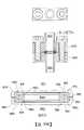
附圖並不意欲按比例繪製。為清楚起見,並非在每一圖式中標明每一組件。在該等圖式中:圖1A係一直徑上截斷之一第一代表性襯墊;圖1B係圖1A中所展示之第一代表性襯墊之一放大橫截面;圖2A係一直徑上截斷之一第二代表性襯墊;圖2B係圖2A中所展示之第二代表性襯墊之一放大橫截面;圖3A係一直徑上截斷之一第三代表性襯墊;圖3B係圖3A中所展示之第三代表性襯墊之一放大橫截面;圖3C係以透視圖展示之圖3A之第三代表性襯墊;圖4A係一直徑上截斷之一第四代表性襯墊;圖4B係第四代表性襯墊之一放大橫截面;圖5A係兩個位置處截斷之一第五代表性襯墊;圖5B係展示該等兩個截斷位置之非直徑(反相)關係之第五代表性襯墊之一平面圖;圖6A繪示在施加軸向密封力以進行結合之前藉由一定位件定位且定位於流體導管端口埋頭孔內之第四代表性襯墊;圖6B繪示在已進行結合之後之流體導管端口埋頭孔中之第四代表性襯墊;圖7A係一直徑上截斷之一第六代表性襯墊;圖7B係圖7A中所展示之第六代表性襯墊之一放大橫截面;圖7C係第六代表性襯墊之一替代實例之一放大橫截面,其中該襯墊之第一軸端表面上之應力集中特徵部包含一應力集中凹槽;圖8A繪示在施加軸向密封力以進行結合之前藉由一定位件定位且定位於具有一平坦底部之一流體導管端口埋頭孔與具有一成形環形突出部之一流體導管端口埋頭孔之間之第六代表性襯墊;圖8B繪示在已進行結合之後之介於對應流體導管端口埋頭孔之間之第六代表性襯墊;圖9A係一直徑上截斷之一第七代表性襯墊;圖9B係圖9A中所展示之第七代表性襯墊之一放大橫截面;圖10A繪示在施加軸向密封力以進行結合之前藉由一定位件定位且定位於流體導管端口埋頭孔內之第七代表性襯墊;圖10B繪示在已進行結合之後之位於流體導管端口埋頭孔中之第七代表性襯墊。The drawings are not intended to be drawn to scale. For clarity, not every component is labeled in every drawing. In these drawings:Figure 1A is a diametrically truncated first representative pad;Figure 1B is an enlarged cross-section of one of the first representative pads shown in Figure 1A;FIG. 2A is a diametrically truncated second representative pad;Figure 2B is an enlarged cross-section of a second representative pad shown in Figure 2A;Figure 3A is a diametrically truncated third representative pad;Figure 3B is an enlarged cross-section of a third representative pad shown in Figure 3A;Figure 3C is a third representative pad of Figure 3A shown in perspective view;Figure 4A is a fourth representative pad truncated in diameter;Figure 4B is an enlarged cross-section of one of the fourth representative pads;Figure 5A is a fifth representative pad truncated at two locations;5B is a plan view of a fifth representative pad showing the non-diametric (inverse) relationship of the two truncation locations;6A depicts a fourth representative gasket positioned by a locator and positioned within a fluid conduit port counterbore prior to application of an axial sealing force for bonding;6B depicts a fourth representative gasket in the fluid conduit port countersink after bonding has been performed;Figure 7A is a sixth representative pad truncated in diameter;Figure 7B is an enlarged cross-section of one of the sixth representative pads shown in Figure 7A;7C is an enlarged cross-section of an alternate example of a sixth representative gasket in which the stress concentration feature on the first shaft end surface of the gasket includes a stress concentration groove;8A depicts positioning by a locator and between a fluid conduit port counterbore with a flat bottom and a fluid conduit port counterbore with a shaped annular protrusion prior to application of an axial sealing force for bonding the sixth representative pad;8B depicts a sixth representative gasket between corresponding fluid conduit port countersinks after bonding has been made;Figure 9A is a seventh representative pad truncated in diameter;Figure 9B is an enlarged cross-section of a seventh representative pad shown in Figure 9A;10A depicts a seventh representative gasket positioned by a locator and positioned within a fluid conduit port counterbore prior to application of an axial sealing force for bonding;10B depicts a seventh representative gasket in a fluid conduit port countersink after bonding has been performed.
900:第七代表性實例/襯墊900: Seventh Representative Example/Pad
920:應力集中特徵部/應力集中凹槽/凹槽920: Stress Concentration Features / Stress Concentration Grooves / Grooves
930:唇緣/襯墊密封區域唇緣/襯墊唇緣/相對襯墊唇緣/第一軸端表面唇緣/相對軸端表面唇緣/密封區域唇緣930: lip / gasket sealing area lip / gasket lip / opposite gasket lip / first shaft end surface lip / opposite shaft end surface lip / sealing area lip
950:襯墊主體950: Pad body
951:孔951: Hole
955:流體通路內孔/襯墊內孔955: Fluid Path Bore/Gasket Bore
956:徑向內部表面956: Radial inner surface
970:應力集中特徵部/應力集中凹槽/凹槽970: Stress Concentration Features / Stress Concentration Grooves / Grooves
980:唇緣/襯墊密封區域唇緣/襯墊唇緣/相對襯墊唇緣/第二軸端表面唇緣/相對軸端表面唇緣/密封區域唇緣980: lip / gasket sealing area lip / gasket lip / opposite gasket lip / second shaft end surface lip / opposite shaft end surface lip / sealing area lip
Claims (15)
Translated fromChineseApplications Claiming Priority (2)
| Application Number | Priority Date | Filing Date | Title |
|---|---|---|---|
| US201461980823P | 2014-04-17 | 2014-04-17 | |
| US61/980,823 | 2014-04-17 |
Publications (2)
| Publication Number | Publication Date |
|---|---|
| TW202138701A TW202138701A (en) | 2021-10-16 |
| TWI773416Btrue TWI773416B (en) | 2022-08-01 |
Family
ID=54321663
Family Applications (6)
| Application Number | Title | Priority Date | Filing Date |
|---|---|---|---|
| TW109104047ATWI736124B (en) | 2014-04-17 | 2015-04-16 | Ring-shaped gasket for sealingly joining opposed fluid conduit ports and method of forming a high purity fluid joint |
| TW111125399ATWI789323B (en) | 2014-04-17 | 2015-04-16 | Ring-shaped gasket for sealingly joining opposed fluid conduit ports and method of forming a high purity fluid joint |
| TW107142092ATWI687611B (en) | 2014-04-17 | 2015-04-16 | Ring-shaped gasket for sealingly joining opposed fluid conduit ports and method of forming a high purity fluid joint |
| TW104112241ATWI652424B (en) | 2014-04-17 | 2015-04-16 | Annular liner for sealingly engaging a relatively fluid conduit port and method of forming a high purity fluid joint |
| TW110124484ATWI773416B (en) | 2014-04-17 | 2015-04-16 | Ring-shaped gasket for sealingly joining opposed fluid conduit ports and method of forming a high purity fluid joint |
| TW111145850ATWI843307B (en) | 2014-04-17 | 2015-04-16 | Ring-shaped gasket for sealingly joining opposed fluid conduit ports and method of forming a high purity fluid joint |
Family Applications Before (4)
| Application Number | Title | Priority Date | Filing Date |
|---|---|---|---|
| TW109104047ATWI736124B (en) | 2014-04-17 | 2015-04-16 | Ring-shaped gasket for sealingly joining opposed fluid conduit ports and method of forming a high purity fluid joint |
| TW111125399ATWI789323B (en) | 2014-04-17 | 2015-04-16 | Ring-shaped gasket for sealingly joining opposed fluid conduit ports and method of forming a high purity fluid joint |
| TW107142092ATWI687611B (en) | 2014-04-17 | 2015-04-16 | Ring-shaped gasket for sealingly joining opposed fluid conduit ports and method of forming a high purity fluid joint |
| TW104112241ATWI652424B (en) | 2014-04-17 | 2015-04-16 | Annular liner for sealingly engaging a relatively fluid conduit port and method of forming a high purity fluid joint |
Family Applications After (1)
| Application Number | Title | Priority Date | Filing Date |
|---|---|---|---|
| TW111145850ATWI843307B (en) | 2014-04-17 | 2015-04-16 | Ring-shaped gasket for sealingly joining opposed fluid conduit ports and method of forming a high purity fluid joint |
Country Status (9)
| Country | Link |
|---|---|
| US (10) | US9739378B2 (en) |
| EP (2) | EP3835629A1 (en) |
| JP (1) | JP6531162B2 (en) |
| KR (5) | KR20250028507A (en) |
| CN (2) | CN106233047B (en) |
| IL (4) | IL304860B1 (en) |
| SG (2) | SG11201608262UA (en) |
| TW (6) | TWI736124B (en) |
| WO (1) | WO2015161029A1 (en) |
Families Citing this family (17)
| Publication number | Priority date | Publication date | Assignee | Title |
|---|---|---|---|---|
| EP3835629A1 (en)* | 2014-04-17 | 2021-06-16 | Compart Systems Pte. Ltd. | Gasket with ultra-sealing effect for joining high purity fluid pathways |
| WO2015179155A1 (en) | 2014-05-19 | 2015-11-26 | Microflex Technologies Llc | Ring seal with sealing surface extension |
| DE102016215304A1 (en)* | 2016-08-17 | 2018-02-22 | Robert Bosch Gmbh | Electromagnetically operated suction valve and high-pressure fuel pump |
| WO2018049356A1 (en)* | 2016-09-09 | 2018-03-15 | Fluidmaster, Inc. | Gasket system and methods of use |
| JP7015672B2 (en)* | 2017-10-24 | 2022-02-03 | Nok株式会社 | gasket |
| JP6948911B2 (en)* | 2017-10-24 | 2021-10-13 | Nok株式会社 | gasket |
| FR3090063B1 (en)* | 2018-12-14 | 2021-03-19 | Commissariat Energie Atomique | METAL SEAL WITH AN EXTERNAL TEXTURED SEALING LAYER |
| JP7382150B2 (en)* | 2019-03-25 | 2023-11-16 | エドワーズ株式会社 | Vacuum pumps and seal members used in vacuum pumps |
| GB201908783D0 (en)* | 2019-06-19 | 2019-07-31 | Tokamak Energy Ltd | Metal sealing ring and method of forming a metal-to-metal seal |
| CN111550621A (en)* | 2020-04-16 | 2020-08-18 | 新兴河北工程技术有限公司 | Socket connecting sealing element for nodular cast iron pipe |
| CN115735331A (en)* | 2020-04-29 | 2023-03-03 | 株式会社Kmw | Filter and method for manufacturing the same |
| JP7193516B2 (en)* | 2020-11-17 | 2022-12-20 | 三菱電線工業株式会社 | metal seal |
| US11555565B2 (en)* | 2020-12-23 | 2023-01-17 | Fiskars Finland Oy Ab | Seal ring and hose connector assembly |
| EP4281694A1 (en)* | 2021-01-22 | 2023-11-29 | Danfoss Power Solutions II Technology A/S | Tube connector systems |
| DE112022001204T5 (en)* | 2021-02-24 | 2024-03-14 | Microflex Technologies Inc. | Ring seal compatible with multiple connection types |
| WO2023219876A1 (en)* | 2022-05-10 | 2023-11-16 | Frederick Rezaei | System and method for sealing a fluid pathway |
| JP7376657B1 (en) | 2022-09-22 | 2023-11-08 | 三菱電線工業株式会社 | Annular metal seal, installation structure of annular metal seal, and installation method of annular metal seal |
Citations (10)
| Publication number | Priority date | Publication date | Assignee | Title |
|---|---|---|---|---|
| US6357760B1 (en)* | 2000-05-19 | 2002-03-19 | Michael Doyle | Ring seal |
| US20090261534A1 (en)* | 2008-04-18 | 2009-10-22 | Le Joint Francais | Sealing gasket and uses of such a gasket |
| US20100044303A1 (en)* | 2006-11-24 | 2010-02-25 | Cummins Filtration Ip Inc. | Filtration cartridge co-operating with a central tube and comprising a radially-retained seal mounted in a cavity for co-operating with said tube |
| CN201651299U (en)* | 2010-03-09 | 2010-11-24 | 广东联塑科技实业有限公司 | A PVC-U-lined steel-plastic composite pipe fitting sealing ring |
| CN201659188U (en)* | 2010-04-23 | 2010-12-01 | 李富龙 | Sealing punch of internal high pressure forming tube end part |
| WO2011024889A1 (en)* | 2009-08-26 | 2011-03-03 | TOKiエンジニアリング株式会社 | Metal seal ring and conduit device using metal seal ring |
| US20110084016A1 (en)* | 2008-03-21 | 2011-04-14 | Cummins Filtration | Filtration assembly including a central tube interacting with a filtration cartridge and with a seal permanently mounted on said central tube |
| CN201924438U (en)* | 2011-01-19 | 2011-08-10 | 厦门市鹭声橡塑有限公司 | Fishbone-shaped seal ring for drainage pipe of water closet |
| US20110304102A1 (en)* | 2010-06-10 | 2011-12-15 | Wartsila Japan Ltd. | Seal ring and stern tube sealing device |
| CN202209425U (en)* | 2011-08-31 | 2012-05-02 | 徐州马龙节能环保设备有限公司 | Sealing structure between main bearing support seat shell and hollow shaft of tube mill |
Family Cites Families (80)
| Publication number | Priority date | Publication date | Assignee | Title |
|---|---|---|---|---|
| US1819036A (en)* | 1925-11-23 | 1931-08-18 | William F Oberhuber | Disk pipe joint |
| GB558544A (en) | 1943-01-01 | 1944-01-10 | Angus George Co Ltd | Improvements in oil seals |
| US2926937A (en)* | 1955-07-05 | 1960-03-01 | Specialties Dev Corp | Fluid tight joint |
| US2841429A (en)* | 1955-10-04 | 1958-07-01 | Parker Hannifin Corp | Sealing ring and joint |
| US2888281A (en)* | 1957-01-23 | 1959-05-26 | Chicago Rawhide Mfg Co | Self-compensating seal |
| US3208758A (en) | 1961-10-11 | 1965-09-28 | Varian Associates | Metal vacuum joint |
| US3158376A (en)* | 1963-05-10 | 1964-11-24 | Minnesota Rubber Co | Low pressure seal |
| US3521910A (en) | 1968-11-12 | 1970-07-28 | Cajon Co | Tube coupling |
| US4266576A (en) | 1977-11-30 | 1981-05-12 | Eaton Corporation | Flow control device in a protective housing |
| US4303251A (en) | 1978-12-04 | 1981-12-01 | Varian Associates, Inc. | Flange sealing joint with removable metal gasket |
| US4344459A (en) | 1980-11-03 | 1982-08-17 | Nelson Walter R | Flow control device employing elastomeric element |
| US4650227B1 (en) | 1982-08-23 | 2000-11-28 | Cajon Co | Fluid coupling |
| US4552389A (en) | 1982-08-23 | 1985-11-12 | Cajon Company | Fluid coupling |
| US4557296A (en) | 1984-05-18 | 1985-12-10 | Byrne Thomas E | Meter tube insert and adapter ring |
| US4830057A (en) | 1987-03-18 | 1989-05-16 | Hendrickson Brothers | Screen and flow regulator assembly |
| US4854597A (en) | 1988-01-22 | 1989-08-08 | General Components, Inc. | Metal gasket having conical and radial sealing surfaces and method of using the gasket with a tubular element |
| US4880034A (en) | 1987-08-10 | 1989-11-14 | Man Design Co., Ltd. | Fluid pressure regulating apparatus |
| FI81186C (en)* | 1989-02-24 | 1990-09-10 | Erkki Rinne | TAETNING. |
| FR2644217A1 (en)* | 1989-03-07 | 1990-09-14 | Procal | STATIC SEAL SEAL |
| US5505464A (en) | 1989-08-11 | 1996-04-09 | General Components, Inc. | Minimum dead volume fitting |
| DE4029183A1 (en) | 1990-09-14 | 1992-03-19 | Dieter Kuhn | FLOW CONTROLLER |
| US5163721A (en) | 1990-10-24 | 1992-11-17 | Cajon Company | Fluid coupling with gasket retainer having interlocking portions |
| US5069252A (en) | 1990-12-18 | 1991-12-03 | Daniel Industries, Inc. | Orifice system intermediate interface |
| US5085250A (en) | 1990-12-18 | 1992-02-04 | Daniel Industries, Inc. | Orifice system |
| US5181542A (en) | 1991-02-22 | 1993-01-26 | Daniel Industries, Inc. | Orifice system mounting assembly |
| JP2540559Y2 (en) | 1991-05-20 | 1997-07-09 | 清原 まさ子 | Pipe Fitting Retainer |
| JPH0512844U (en)* | 1991-07-30 | 1993-02-19 | 日東工器株式会社 | Seal ring |
| US5401065A (en) | 1992-05-11 | 1995-03-28 | Kabushiki Kaisha Toshiba | Fluid coupling |
| WO1995010001A1 (en) | 1993-10-06 | 1995-04-13 | Unit Instruments, Inc. | Apparatus for handling process fluid |
| JP3388291B2 (en) | 1993-10-28 | 2003-03-17 | 忠弘 大見 | Pipe fittings |
| US5423580A (en) | 1994-01-26 | 1995-06-13 | Cajon Company | Fluid coupling with gasket retainer |
| JP3661040B2 (en) | 1995-05-31 | 2005-06-15 | 忠弘 大見 | Fluid control device |
| US5673946A (en) | 1995-07-07 | 1997-10-07 | Ewal Manufacturing Co., Inc. | Gasket assembly for a fluid coupling |
| CA2176652C (en) | 1995-08-09 | 2007-07-17 | Tadahiro Ohmi | Pipe joint |
| JP2991651B2 (en) | 1995-12-25 | 1999-12-20 | シーケーディ株式会社 | Metal gasket |
| CN1165260A (en)* | 1996-05-10 | 1997-11-19 | 益冈照明 | O-ring of multi-lobular cross section |
| JP3122386B2 (en) | 1996-07-16 | 2001-01-09 | シーケーディ株式会社 | Gasket holder |
| TW354821B (en) | 1996-10-15 | 1999-03-21 | Tadahiro Omi | Fluid coupling |
| US5992463A (en) | 1996-10-30 | 1999-11-30 | Unit Instruments, Inc. | Gas panel |
| US5713582A (en) | 1997-01-03 | 1998-02-03 | Eg&G Pressure Science, Inc. | Seal retainer |
| US5730448A (en) | 1997-01-03 | 1998-03-24 | Eg&G Pressure Science, Inc. | Seal retainer plate |
| US6623047B2 (en) | 1997-06-16 | 2003-09-23 | Swagelok Company | Tube coupling |
| JP3876351B2 (en) | 1997-06-18 | 2007-01-31 | 忠弘 大見 | Pipe fitting |
| US6318766B1 (en) | 1997-09-15 | 2001-11-20 | Swagelok Company | Face seal gland with raised peripheral ring having circumferentially spaced recesses |
| JPH11108198A (en)* | 1997-10-01 | 1999-04-20 | Nok Corp | Sealing device |
| US6158455A (en) | 1998-08-06 | 2000-12-12 | Marshall; William H. | Antifreeze cap for faucet |
| JP2001082609A (en)* | 1999-09-09 | 2001-03-30 | Motoyama Eng Works Ltd | Seal gasket |
| FR2806144B1 (en)* | 2000-03-09 | 2002-04-26 | Legris Sa | QUADRILOBE SECTION ANNULAR SEAL |
| US6409180B1 (en) | 2000-04-21 | 2002-06-25 | Perkinelmer, Inc. | Metallic seal |
| US6539968B1 (en) | 2000-09-20 | 2003-04-01 | Fugasity Corporation | Fluid flow controller and method of operation |
| JP4517325B2 (en) | 2000-10-05 | 2010-08-04 | 忠弘 大見 | Fluid coupling |
| US6845984B2 (en) | 2000-11-27 | 2005-01-25 | Michael Doyle | Keeper for positioning ring seals |
| US6561521B2 (en)* | 2001-03-27 | 2003-05-13 | Fmc Technologies, Inc. | Metal-to-metal seal with soft metal insert |
| US6945539B2 (en) | 2002-02-20 | 2005-09-20 | Garlock Sealing Technologies Llc | Seal retainer |
| JP3986380B2 (en)* | 2002-06-26 | 2007-10-03 | トピー工業株式会社 | Track seal |
| US7045936B2 (en)* | 2002-10-01 | 2006-05-16 | Hitachi Electronic Devices (Usa), Inc. | Projection coupler with contrast ribs |
| US7169231B2 (en) | 2002-12-13 | 2007-01-30 | Lam Research Corporation | Gas distribution system with tuning gas |
| EP1634001B1 (en)* | 2003-06-16 | 2013-05-01 | Huhnseal AB | Pressure resistant static and dynamic expeller shaft sealing |
| JP4193612B2 (en) | 2003-06-30 | 2008-12-10 | オムロン株式会社 | Rectifier mounting structure |
| FR2857076B1 (en)* | 2003-07-01 | 2005-09-30 | Joint Francais | ANNULAR JOINT FOR CONNECTING FLUID TRANSFER AND CONNECTION EQUIPPED WITH SUCH A SEAL. |
| FR2866410B1 (en) | 2004-02-17 | 2006-05-19 | Gaz De France | FLOW CONDITIONER FOR FLUID TRANSPORT PIPING |
| US7086131B2 (en)* | 2004-05-14 | 2006-08-08 | Victaulic Company | Deformable mechanical pipe coupling |
| SE527822C2 (en)* | 2004-09-23 | 2006-06-13 | G A Gold Seal Dev Ltd C O Kpmg | Gasket for e.g. sealing joints e.g. flanges, tube or pipe couplings has inner portion formed with an angled wall, which when expands inwardly interacts with matching angled wall of seat |
| JP4589686B2 (en)* | 2004-09-28 | 2010-12-01 | 興国インテック株式会社 | Double adsorption gasket |
| US7823889B2 (en)* | 2004-09-30 | 2010-11-02 | Eagle Industry Aerospace Co., Ltd. | Seal part |
| US7222643B2 (en) | 2004-10-21 | 2007-05-29 | Vernay Laboratories, Inc. | Internal post flow control |
| US7314590B2 (en)* | 2005-09-20 | 2008-01-01 | Bayer Materialscience Llc | Method of preparing a coated molded plastic article |
| WO2007066630A1 (en)* | 2005-12-06 | 2007-06-14 | Nok Corporation | Rod sealing system |
| EP1967773B1 (en)* | 2007-03-07 | 2009-12-02 | Le Joint Francais | Y-Seal, method of manufacturing such a seal and its use to reduce the forces for fitting a connector |
| JP5204550B2 (en)* | 2008-05-20 | 2013-06-05 | 国立大学法人東北大学 | Metal gasket |
| TW201000788A (en)* | 2008-06-24 | 2010-01-01 | Wen-Chi Wu | Washer and pipe joint utilizing the washer |
| CN201461935U (en)* | 2009-07-30 | 2010-05-12 | 南方天合底盘系统有限公司 | High-intensity sealing leather collar |
| US8356843B2 (en) | 2010-09-27 | 2013-01-22 | Hamilton Sundstrand Corporation | Refrigeration system connection fitting |
| JP5748155B2 (en) | 2010-12-23 | 2015-07-15 | イーグル工業株式会社 | Sealing device using magnetic fluid |
| JP5973781B2 (en)* | 2011-07-20 | 2016-08-23 | 三菱電線工業株式会社 | Corrosion-resistant composite seal structure |
| CN202510708U (en)* | 2012-03-29 | 2012-10-31 | 上海通用汽车有限公司 | Automotive high-pressure steering oil pipe sealing gasket |
| JP5102908B1 (en)* | 2012-04-12 | 2012-12-19 | ニチアス株式会社 | Metal gasket |
| WO2014019580A1 (en)* | 2012-08-02 | 2014-02-06 | Schaeffler Technologies AG & Co. KG | Slave cylinder for a hydraulic disengagement arrangement for operating a clutch |
| CN203384366U (en)* | 2013-08-08 | 2014-01-08 | 安徽宇金机电工程有限公司 | Improved sealing gasket |
| EP3835629A1 (en)* | 2014-04-17 | 2021-06-16 | Compart Systems Pte. Ltd. | Gasket with ultra-sealing effect for joining high purity fluid pathways |
- 2015
- 2015-04-16EPEP21153442.5Apatent/EP3835629A1/enactivePending
- 2015-04-16TWTW109104047Apatent/TWI736124B/enactive
- 2015-04-16ILIL304860Apatent/IL304860B1/enunknown
- 2015-04-16USUS14/688,153patent/US9739378B2/enactiveActive
- 2015-04-16WOPCT/US2015/026093patent/WO2015161029A1/enactiveApplication Filing
- 2015-04-16TWTW111125399Apatent/TWI789323B/enactive
- 2015-04-16KRKR1020257004923Apatent/KR20250028507A/enactivePending
- 2015-04-16KRKR1020237039496Apatent/KR102770377B1/enactiveActive
- 2015-04-16KRKR1020227044680Apatent/KR102604479B1/enactiveActive
- 2015-04-16KRKR1020227002878Apatent/KR102480804B1/enactiveActive
- 2015-04-16TWTW107142092Apatent/TWI687611B/enactive
- 2015-04-16ILIL284910Apatent/IL284910B2/enunknown
- 2015-04-16TWTW104112241Apatent/TWI652424B/enactive
- 2015-04-16EPEP15779865.3Apatent/EP3132162B1/enactiveActive
- 2015-04-16JPJP2017506623Apatent/JP6531162B2/enactiveActive
- 2015-04-16TWTW110124484Apatent/TWI773416B/enactive
- 2015-04-16TWTW111145850Apatent/TWI843307B/enactive
- 2015-04-16KRKR1020167028786Apatent/KR102357624B1/enactiveActive
- 2015-04-16CNCN201580020189.3Apatent/CN106233047B/enactiveActive
- 2015-04-16SGSG11201608262UApatent/SG11201608262UA/enunknown
- 2015-04-16CNCN201811091175.2Apatent/CN108980353B/enactiveActive
- 2015-04-16SGSG10202000471YApatent/SG10202000471YA/enunknown
- 2016
- 2016-09-27ILIL248085Apatent/IL248085B/enunknown
- 2017
- 2017-07-05USUS15/641,752patent/US9970547B2/enactiveActive
- 2018
- 2018-04-19USUS15/957,177patent/US10982768B2/enactiveActive
- 2018-05-14USUS15/979,304patent/US10422429B2/enactiveActive
- 2018-05-14USUS15/979,290patent/US10533662B2/enactiveActive
- 2019
- 2019-12-06USUS16/705,980patent/US11300205B2/enactiveActive
- 2019-12-06USUS16/705,988patent/US11255433B2/enactiveActive
- 2021
- 2021-04-19USUS17/234,514patent/US11781651B2/enactiveActive
- 2023
- 2023-09-05USUS18/242,238patent/US12055218B2/enactiveActive
- 2024
- 2024-07-09USUS18/767,439patent/US20250043865A1/enactivePending
- 2025
- 2025-05-21ILIL321077Apatent/IL321077A/enunknown
Patent Citations (11)
| Publication number | Priority date | Publication date | Assignee | Title |
|---|---|---|---|---|
| US6357760B1 (en)* | 2000-05-19 | 2002-03-19 | Michael Doyle | Ring seal |
| US20100044303A1 (en)* | 2006-11-24 | 2010-02-25 | Cummins Filtration Ip Inc. | Filtration cartridge co-operating with a central tube and comprising a radially-retained seal mounted in a cavity for co-operating with said tube |
| US20110084016A1 (en)* | 2008-03-21 | 2011-04-14 | Cummins Filtration | Filtration assembly including a central tube interacting with a filtration cartridge and with a seal permanently mounted on said central tube |
| US20090261534A1 (en)* | 2008-04-18 | 2009-10-22 | Le Joint Francais | Sealing gasket and uses of such a gasket |
| WO2011024889A1 (en)* | 2009-08-26 | 2011-03-03 | TOKiエンジニアリング株式会社 | Metal seal ring and conduit device using metal seal ring |
| TWI575173B (en)* | 2009-08-26 | 2017-03-21 | Toki Engineering Co Ltd | A metal sealing ring and a conduit device using the metal sealing ring |
| CN201651299U (en)* | 2010-03-09 | 2010-11-24 | 广东联塑科技实业有限公司 | A PVC-U-lined steel-plastic composite pipe fitting sealing ring |
| CN201659188U (en)* | 2010-04-23 | 2010-12-01 | 李富龙 | Sealing punch of internal high pressure forming tube end part |
| US20110304102A1 (en)* | 2010-06-10 | 2011-12-15 | Wartsila Japan Ltd. | Seal ring and stern tube sealing device |
| CN201924438U (en)* | 2011-01-19 | 2011-08-10 | 厦门市鹭声橡塑有限公司 | Fishbone-shaped seal ring for drainage pipe of water closet |
| CN202209425U (en)* | 2011-08-31 | 2012-05-02 | 徐州马龙节能环保设备有限公司 | Sealing structure between main bearing support seat shell and hollow shaft of tube mill |
Also Published As
Similar Documents
| Publication | Publication Date | Title |
|---|---|---|
| TWI773416B (en) | Ring-shaped gasket for sealingly joining opposed fluid conduit ports and method of forming a high purity fluid joint | |
| TWI892600B (en) | Ring-shaped gasket for sealingly joining opposed fluid conduit ports and method of forming a high purity fluid joint | |
| HK40056477A (en) | Gasket with ultra-sealing effect for joining high purity fluid pathways | |
| HK1228985B (en) | Ultra-seal gasket for joining high purity fluid pathways | |
| HK1228985A1 (en) | Ultra-seal gasket for joining high purity fluid pathways |