TWI773008B - Ultrasonic atomization apparatus - Google Patents
Ultrasonic atomization apparatusDownload PDFInfo
- Publication number
- TWI773008B TWI773008BTW109143674ATW109143674ATWI773008BTW I773008 BTWI773008 BTW I773008BTW 109143674 ATW109143674 ATW 109143674ATW 109143674 ATW109143674 ATW 109143674ATW I773008 BTWI773008 BTW I773008B
- Authority
- TW
- Taiwan
- Prior art keywords
- ultrasonic
- water tank
- cup
- reflected wave
- ultrasonic vibration
- Prior art date
Links
- 238000000889atomisationMethods0.000titleabstractdescription11
- XLYOFNOQVPJJNP-UHFFFAOYSA-NwaterSubstancesOXLYOFNOQVPJJNP-UHFFFAOYSA-N0.000claimsabstractdescription95
- 238000002955isolationMethods0.000claimsdescription44
- 239000002994raw materialSubstances0.000claimsdescription40
- 125000006850spacer groupChemical group0.000claimsdescription35
- 230000005540biological transmissionEffects0.000claimsdescription16
- 239000000463materialSubstances0.000claimsdescription11
- 239000000470constituentSubstances0.000claimsdescription10
- 239000007789gasSubstances0.000description21
- 239000002245particleSubstances0.000description19
- 238000010586diagramMethods0.000description17
- 239000007788liquidSubstances0.000description16
- 239000012159carrier gasSubstances0.000description8
- 238000010521absorption reactionMethods0.000description6
- 230000004048modificationEffects0.000description5
- 238000012986modificationMethods0.000description5
- 239000004743PolypropyleneSubstances0.000description4
- 229920001971elastomerPolymers0.000description4
- 239000010419fine particleSubstances0.000description4
- 230000015572biosynthetic processEffects0.000description3
- 230000000694effectsEffects0.000description3
- 238000000034methodMethods0.000description3
- 230000002093peripheral effectEffects0.000description3
- 239000002904solventSubstances0.000description3
- 238000002604ultrasonographyMethods0.000description3
- 238000009825accumulationMethods0.000description2
- 238000006243chemical reactionMethods0.000description2
- 238000001816coolingMethods0.000description2
- 230000009977dual effectEffects0.000description2
- 238000004519manufacturing processMethods0.000description2
- 239000003595mistSubstances0.000description2
- 230000035515penetrationEffects0.000description2
- -1polypropylenePolymers0.000description2
- 229920001155polypropylenePolymers0.000description2
- 239000000758substrateSubstances0.000description2
- 239000010409thin filmSubstances0.000description2
- 239000011800void materialSubstances0.000description2
- RYGMFSIKBFXOCR-UHFFFAOYSA-NCopperChemical compound[Cu]RYGMFSIKBFXOCR-UHFFFAOYSA-N0.000description1
- 229920000181Ethylene propylene rubberPolymers0.000description1
- 206010067482No adverse eventDiseases0.000description1
- 229920006311Urethane elastomerPolymers0.000description1
- 230000002411adverseEffects0.000description1
- 229920005549butyl rubberPolymers0.000description1
- 239000000498cooling waterSubstances0.000description1
- 229910052802copperInorganic materials0.000description1
- 239000010949copperSubstances0.000description1
- 238000005260corrosionMethods0.000description1
- 230000007797corrosionEffects0.000description1
- 230000007423decreaseEffects0.000description1
- 239000010408filmSubstances0.000description1
- 229920001973fluoroelastomerPolymers0.000description1
- 239000011261inert gasSubstances0.000description1
- 230000014759maintenance of locationEffects0.000description1
- 239000000203mixtureSubstances0.000description1
- 238000005192partitionMethods0.000description1
- 239000004810polytetrafluoroethyleneSubstances0.000description1
- 229920001343polytetrafluoroethylenePolymers0.000description1
- 229920002379silicone rubberPolymers0.000description1
- 239000004945silicone rubberSubstances0.000description1
- 238000005507sprayingMethods0.000description1
- 229910001220stainless steelInorganic materials0.000description1
- 239000010935stainless steelSubstances0.000description1
- 238000000427thin-film depositionMethods0.000description1
- 125000000391vinyl groupChemical group[H]C([*])=C([H])[H]0.000description1
- 229920002554vinyl polymerPolymers0.000description1
Images


Classifications
- B—PERFORMING OPERATIONS; TRANSPORTING
- B05—SPRAYING OR ATOMISING IN GENERAL; APPLYING FLUENT MATERIALS TO SURFACES, IN GENERAL
- B05B—SPRAYING APPARATUS; ATOMISING APPARATUS; NOZZLES
- B05B17/00—Apparatus for spraying or atomising liquids or other fluent materials, not covered by the preceding groups
- B05B17/04—Apparatus for spraying or atomising liquids or other fluent materials, not covered by the preceding groups operating with special methods
- B05B17/06—Apparatus for spraying or atomising liquids or other fluent materials, not covered by the preceding groups operating with special methods using ultrasonic or other kinds of vibrations
- B05B17/0607—Apparatus for spraying or atomising liquids or other fluent materials, not covered by the preceding groups operating with special methods using ultrasonic or other kinds of vibrations generated by electrical means, e.g. piezoelectric transducers
- B05B17/0615—Apparatus for spraying or atomising liquids or other fluent materials, not covered by the preceding groups operating with special methods using ultrasonic or other kinds of vibrations generated by electrical means, e.g. piezoelectric transducers spray being produced at the free surface of the liquid or other fluent material in a container and subjected to the vibrations
- B—PERFORMING OPERATIONS; TRANSPORTING
- B05—SPRAYING OR ATOMISING IN GENERAL; APPLYING FLUENT MATERIALS TO SURFACES, IN GENERAL
- B05B—SPRAYING APPARATUS; ATOMISING APPARATUS; NOZZLES
- B05B17/00—Apparatus for spraying or atomising liquids or other fluent materials, not covered by the preceding groups
- B05B17/04—Apparatus for spraying or atomising liquids or other fluent materials, not covered by the preceding groups operating with special methods
- B05B17/06—Apparatus for spraying or atomising liquids or other fluent materials, not covered by the preceding groups operating with special methods using ultrasonic or other kinds of vibrations
- B05B17/0607—Apparatus for spraying or atomising liquids or other fluent materials, not covered by the preceding groups operating with special methods using ultrasonic or other kinds of vibrations generated by electrical means, e.g. piezoelectric transducers
- B05B17/0653—Details
- B—PERFORMING OPERATIONS; TRANSPORTING
- B05—SPRAYING OR ATOMISING IN GENERAL; APPLYING FLUENT MATERIALS TO SURFACES, IN GENERAL
- B05B—SPRAYING APPARATUS; ATOMISING APPARATUS; NOZZLES
- B05B7/00—Spraying apparatus for discharge of liquids or other fluent materials from two or more sources, e.g. of liquid and air, of powder and gas
- B05B7/0012—Apparatus for achieving spraying before discharge from the apparatus
- B—PERFORMING OPERATIONS; TRANSPORTING
- B05—SPRAYING OR ATOMISING IN GENERAL; APPLYING FLUENT MATERIALS TO SURFACES, IN GENERAL
- B05B—SPRAYING APPARATUS; ATOMISING APPARATUS; NOZZLES
- B05B7/00—Spraying apparatus for discharge of liquids or other fluent materials from two or more sources, e.g. of liquid and air, of powder and gas
- B05B7/24—Spraying apparatus for discharge of liquids or other fluent materials from two or more sources, e.g. of liquid and air, of powder and gas with means, e.g. a container, for supplying liquid or other fluent material to a discharge device
- B05B7/2489—Spraying apparatus for discharge of liquids or other fluent materials from two or more sources, e.g. of liquid and air, of powder and gas with means, e.g. a container, for supplying liquid or other fluent material to a discharge device an atomising fluid, e.g. a gas, being supplied to the discharge device
- B05B7/2491—Spraying apparatus for discharge of liquids or other fluent materials from two or more sources, e.g. of liquid and air, of powder and gas with means, e.g. a container, for supplying liquid or other fluent material to a discharge device an atomising fluid, e.g. a gas, being supplied to the discharge device characterised by the means for producing or supplying the atomising fluid, e.g. air hoses, air pumps, gas containers, compressors, fans, ventilators, their drives
Landscapes
- Special Spraying Apparatus (AREA)
- Pressure-Spray And Ultrasonic-Wave- Spray Burners (AREA)
Abstract
Description
Translated fromChinese本發明係關於一種超音波霧化裝置,其係採用超音波振動件將原料溶液霧化成微細的液滴(微粒液滴化),並將該微粒液滴(mist)送至外部。The present invention relates to an ultrasonic atomizing device, which uses an ultrasonic vibration member to atomize a raw material solution into fine droplets (mist), and sends the mist to the outside.
電子裝置的製作現場,有時會利用到超音波霧化裝置。該電子裝置製造的領域中,超音波霧化裝置係利用超音波振動件所振盪的超音波將溶液微粒液滴化,並藉由載送氣體將經微粒液滴化的溶液往外部送出。藉由將送出該外部的原料溶液微粒液滴對基板進行噴霧,使電子裝置用的薄膜成膜於基板上。In the production site of electronic devices, ultrasonic atomization devices are sometimes used. In the field of electronic device manufacturing, the ultrasonic atomization device utilizes the ultrasonic wave oscillated by the ultrasonic vibrating element to drop the solution particles, and sends the droplet solution to the outside by the carrier gas. The thin film for electronic devices is formed on the substrate by spraying the droplets of the raw material solution fine particles sent out to the substrate.
成膜製程中使用的原料溶液會使用各式各樣的溶媒,為了防止超音波振動件腐蝕而採用原料溶液與超音波振動件不接觸的雙反應室方式(double chamber method)。雙反應室方式中,為了隔開超音波振動件與原料溶液,除了底面設有超音波振動件的水槽之外,另採用收容原料溶液的隔離杯。隔離杯須使超音波穿透,但其一部份會反射超音波。再者,水槽中收容有超音波傳達溶媒。Various solvents are used for the raw material solution used in the film forming process. In order to prevent corrosion of the ultrasonic vibration member, a double chamber method is adopted in which the raw material solution does not contact the ultrasonic vibration member. In the dual reaction chamber method, in order to separate the ultrasonic vibrating member and the raw material solution, in addition to the water tank with the ultrasonic vibrating member on the bottom surface, an isolation cup for containing the raw material solution is also used. The isolation cup must allow the ultrasound to penetrate, but a portion of it will reflect the ultrasound. Furthermore, the ultrasonic transmission medium is accommodated in the water tank.
就上述的雙反應室方式的超音波霧化裝置而言,例如有專利文獻1中揭示的霧化裝置。As an ultrasonic atomizing device of the above-mentioned dual reaction chamber system, there is the atomizing device disclosed in Patent Document 1, for example.
[先前技術文獻][Prior Art Literature]
[專利文獻][Patent Literature]
[專利文獻1]國際公開第2015/019468號[Patent Document 1] International Publication No. 2015/019468
將超音波從設於水槽底面的超音波振動件通過非活性液體的超音波傳達溶媒而入射至(傳達到)隔離杯的底面時,會產生透射波與反射波。透射波係穿透隔離杯的底面而入射至原料溶液,反射波係射向水槽的底面。Transmitted waves and reflected waves are generated when ultrasonic waves are incident on (transmitted) the bottom surface of the isolation cup from the ultrasonic vibrator provided on the bottom surface of the water tank through the ultrasonic transmission medium of inactive liquid. The transmitted wave system penetrates the bottom surface of the isolation cup and is incident on the raw material solution, and the reflected wave system is directed to the bottom surface of the water tank.
為了使全部皆成為透射波而不產生反射波,就超音波傳達溶媒及隔離杯(的底面)之構成材料而言,須採用具有相同之聲阻抗的構成材料。然而,實際上極難以使兩者之構成材料之聲阻抗完全一致,而必然會產生反射波。In order to make all of them become transmitted waves without generating reflected waves, as far as the constituent materials of the ultrasonic transmission medium and (the bottom surface of the isolation cup) are concerned, constituent materials with the same acoustic impedance must be used. However, in fact, it is extremely difficult to make the acoustic impedances of the two constituent materials completely consistent, and reflected waves will inevitably be generated.
反射波係向水槽的底面側傳達,因此,隨著承受反射波,會發生水槽(的底面)溶融、設於水槽底面的超音波振動件故障等情形,因而成為超音波霧化裝置壽命縮短的原因。因此,習知的超音波霧化裝置有耐久性不佳的問題點。The reflected wave is transmitted to the bottom surface side of the water tank. Therefore, as the reflected wave is received, the (bottom surface) of the water tank (the bottom surface) may melt, and the ultrasonic vibrating element installed on the bottom surface of the water tank may fail, which shortens the life of the ultrasonic atomizer. reason. Therefore, the conventional ultrasonic atomizing device has a problem of poor durability.
本發明中之目的在於提供一種解決如上述問題點而謀求耐久性提升之超音波霧化裝置。An object of the present invention is to provide an ultrasonic atomizer device that solves the above problems and seeks to improve durability.
本發明之超音波霧化裝置係具備:容器,係在其下方具有要收容原料溶液的隔離杯;內部為空洞的內部空洞構造體,係在前述容器內部設於前述隔離杯的上方;以及水槽,係在其內部收容超音波傳達媒體;前述水槽及前述隔離杯係定位成為前述隔離杯的底面浸入前述超音波傳達媒體;前述超音波霧化裝置更具備設於前述水槽的底面的至少一個超音波振動件;從前述至少一個超音波振動件發送的至少一個入射波的一部份係在前述隔離杯的底面反射,藉此獲得至少一個底面反射波;前述隔離杯及前述至少一個超音波振動件係設置成滿足反射波回避條件;前述反射波回避條件為「前述至少一個超音波振動件的任一者皆不會接收到前述至少一個底面反射波」之條件;前述隔離杯的底面係形成為中央向下方突出的球面狀;前述至少一個超音波振動件係包含複數個超音波振動件,前述至少一個入射波係包含複數個入射波,前述至少一個底面反射波係包含複數個底面反射波,前述反射波回避條件為「前述複數個底面反射波皆不會被發送到前述複數個超音波振動件的任一者」之條件;前述複數個超音波振動件係互相分離配置成距前述水槽的底面之基準點相同距離;前述水槽的底面係具有接收前述複數個底面反射波的複數個反射波接收區域;前述超音波霧化裝置更具備設於前述複數個反射波接收區域的複數個超音波吸收構件;前述複數個反射波接收區域係與前述複數個超音波振動件的形成區域不同的區域。The ultrasonic atomizing device of the present invention is provided with: a container with a spacer cup under which the raw material solution is to be accommodated; an inner hollow structure with a hollow inside, which is arranged above the spacer cup inside the container; and a water tank , the ultrasonic transmission medium is accommodated in its interior; the water tank and the isolation cup are positioned so that the bottom surface of the isolation cup is immersed into the ultrasonic transmission medium; the ultrasonic atomization device is further provided with at least one ultrasonic transmission medium arranged on the bottom surface of the water tank. Sonic vibration member; a part of at least one incident wave sent from the at least one ultrasonic vibration member is reflected on the bottom surface of the isolation cup, thereby obtaining at least one bottom reflected wave; the isolation cup and the at least one ultrasonic vibration The device is set to meet the reflected wave avoidance condition; the aforementioned reflected wave avoidance condition is the condition that “any of the aforementioned at least one ultrasonic vibration member will not receive the aforementioned at least one bottom surface reflected wave”; the bottom surface of the aforementioned isolation cup is formed It is a spherical shape with the center protruding downward; the at least one ultrasonic vibration member includes a plurality of ultrasonic vibration members, the at least one incident wave system includes a plurality of incident waves, and the at least one bottom-reflected wave system includes a plurality of bottom-reflected waves , the above-mentioned reflection wave avoidance condition is the condition that "the plurality of bottom surface reflected waves will not be sent to any one of the plurality of ultrasonic vibration members"; the plurality of ultrasonic vibration members are separated from each other and arranged to be away from the water tank. The bottom surface of the water tank has the same distance from the reference point of the bottom surface; the bottom surface of the water tank has a plurality of reflected wave receiving areas for receiving the reflected waves from the bottom surface; A sound wave absorbing member; the plurality of reflected wave receiving regions are different regions from the forming regions of the plurality of ultrasonic vibration members.
第一態樣所述之本發明的超音波霧化裝置中,隔離杯及至少一個超音波振動件係設置成滿足上述反射波回避條件。In the ultrasonic atomizing device of the present invention described in the first aspect, the isolation cup and at least one ultrasonic vibrating member are set to satisfy the above-mentioned reflected wave avoidance condition.
結果,第一態樣所述之本發明的超音波霧化裝置不會產生因為至少一個超音波振動件承受至少一個底面反射波所致之故障等不良影響,故可謀求耐久性的提升。As a result, the ultrasonic atomizing device of the present invention described in the first aspect does not have adverse effects such as failure due to at least one ultrasonic vibrating element being subjected to at least one reflected wave from the bottom surface, so that the durability can be improved.
藉由以下的詳細說明及所附圖式應可更明瞭本發明之目的、特徵、態樣、及優點。The objects, features, aspects, and advantages of the present invention should become more apparent from the following detailed description and the accompanying drawings.
1,51:容器1,51: Container
1H:氣體供給空間1H: Gas supply space
2:超音波振動件2: Ultrasonic vibration parts
3:內部空洞構造體3: Internal void structure
3A:管部3A: Tube Department
3B:圓錐台部3B: truncated cone
3C:圓筒部3C: Cylinder part
3H:微粒液滴化空間3H: particle dropletization space
4:氣體供給部4: Gas supply part
4a:供給口4a: Supply port
5:連接部5: Connection part
6:液柱6: Liquid column
9:超音波傳達水9: Ultrasonic conveys water
10,10B,10C:水槽10, 10B, 10C: Sink
11:上部杯11: Upper Cup
12,62:隔離杯12,62: Isolation Cup
15:原料溶液15: raw material solution
15A:液面15A: Liquid level
22:超音波振動板22: Ultrasonic vibration plate
23:支撐橡膠23: Support rubber
24:基台24: Abutment
25,27:超音波吸收構件25, 27: Ultrasonic Absorbing Components
29:冷卻管路29: Cooling line
32:超音波反射構件32: Ultrasonic reflection member
101至103,200:超音波霧化裝置101 to 103,200: Ultrasonic atomizing devices
BP1,BP6:底面BP1, BP6: Bottom
C1,C6,C10:中心點C1, C6, C10: center point
D1,D6:距離D1, D6: Distance
G4:載送氣體G4: Carrier gas
H15:液面高度H15: Liquid level
MT:原料溶液微粒液滴MT: raw material solution particle droplets
OP2:開放區域OP2: Open area
r1,r6:曲率半徑r1,r6: radius of curvature
RS:區域RS: area
W1:入射波W1: Incident wave
W2至W4:反射波W2 to W4: Reflected waves
W11:透射波W11: transmitted wave
W31:二次透射波W31: Second transmitted wave
圖1係示意顯示本發明之實施型態1的超音波霧化裝置之構成的說明圖。FIG. 1 is an explanatory diagram schematically showing the configuration of an ultrasonic atomizing device according to Embodiment 1 of the present invention.
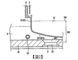
圖2係顯示一超音波振動件之周邊構造之詳細的說明圖(其1)。FIG. 2 is a detailed explanatory diagram (No. 1) showing the peripheral structure of an ultrasonic vibration member.
圖3係顯示一超音波振動件之周邊構造之詳細的說明圖(其2)。Fig. 3 is a detailed explanatory diagram (No. 2) showing the peripheral structure of an ultrasonic vibration member.
圖4係示意顯示習知的隔離杯的底面的曲率半徑的說明圖。FIG. 4 is an explanatory diagram schematically showing the radius of curvature of the bottom surface of a conventional spacer cup.
圖5係顯示隔離杯的底面的曲率半徑與超音波振動件的配置態樣的說明圖。FIG. 5 is an explanatory diagram showing the radii of curvature of the bottom surface of the spacer cup and the arrangement of the ultrasonic vibrator.
圖6係顯示實施型態1的隔離杯的底面的曲率半徑與超音波振動件的配置態樣的說明圖。FIG. 6 is an explanatory diagram showing the radii of curvature of the bottom surface of the spacer cup according to Embodiment 1 and the arrangement of the ultrasonic vibrator.
圖7係顯示實施型態1的水槽的底面配置四個超音波振動件的配置態樣的俯視圖。7 is a plan view showing an arrangement aspect in which four ultrasonic vibrators are arranged on the bottom surface of the water tank according to Embodiment 1. FIG.
圖8係顯示圖7之A-A剖面之超音波振動件的剖面圖。FIG. 8 is a cross-sectional view of the ultrasonic vibrating member showing the section A-A of FIG. 7 .
圖9係示意顯示本發明之實施型態2的超音波霧化裝置之構成的說明圖。FIG. 9 is an explanatory diagram schematically showing the configuration of the ultrasonic atomizing device according to the second embodiment of the present invention.
圖10係示意顯示本發明之實施型態3的超音波霧化裝置之構成的說明圖。FIG. 10 is an explanatory diagram schematically showing the configuration of the ultrasonic atomizing device according to
圖11係示意顯示習知的超音波霧化裝置之構成的說明圖。FIG. 11 is an explanatory diagram schematically showing the structure of a conventional ultrasonic atomizing device.
<實施型態1><implementation type 1>
圖1係示意顯示本發明之實施型態1的超音波霧化裝置101之構成的說明圖。FIG. 1 is an explanatory diagram schematically showing the configuration of an
如圖1所示,超音波霧化裝置101係具備容器1、作為微粒液滴化手段的超音波振動件2、內部空洞構造體3、及氣體供給部4。容器1係呈藉由連接部5結合上部杯11及隔離杯12而成的構造。此外,超音波振動件2就主要部分而言,具有超音波振動板22。As shown in FIG. 1 , an
上部杯11若為內部形成空間的容器,則可為任何形狀。超音波霧化裝置101中,上部杯11為大致圓筒形狀,且上部杯11內形成俯視觀察時形成為圓形的側面包圍而成的空間。另一方面,隔離杯12內係可收容原料溶液15。The
超音波振動件2係從內部的超音波振動板22對隔離杯12內的原料溶液15施加超音波,藉此使原料溶液15微粒液滴化(霧化)。四個超音波振動件2(圖1僅顯示兩個)係配設於水槽10的底面。圖1中僅示意顯示,但超音波振動件2的上方為開放狀態。在此,超音波振動件2的數量不限於四個,可為一個亦可為兩個以上。The
內部空洞構造體3係內部具有空洞的構造體。容器1的上部杯11之上表面部形成有開口部,且如圖1所示,內部空洞構造體3配設成經由該開口部插通上部杯11內。在此,內部空洞構造體3插通開口部的狀態下,內部空洞構造體3與上部杯11之間為密閉狀態。亦即,內部空洞構造體3與上部杯11的上述開口部之間被封接。
內部空洞構造體3的形狀若為內部形成空洞的形狀,則可採用任何形狀。圖1之構成例中,內部空洞構造體3係具備不具有底面之燒瓶形狀的剖面形狀。更具體而言,圖1所示的內部空洞構造體3係由管部3A、圓錐台部3B、及圓筒部3C所構成。Any shape may be adopted as the shape of the
管部3A為圓筒形狀的管路部,該管部3A係插通上部杯11之上表面所設的開口部而從上部杯11外部通到上部杯11內部。更具體而言,管部3A區分為配設於上部杯11之外側的上管部及配設於上部杯11之內部的下管部。而且,上管部係從上部杯11之上表面外側安裝,下管部係從上部杯11之上表面內側安裝,在安裝有該等構件的狀態下,上管部與下管部係通過配設於上部杯11之上表面的開口部而連通。管部3A之一方端部係連接到位於上部杯11之外之例如利用原料溶液微粒液滴MT進行薄膜的成膜的薄膜成膜裝置。另一方面,管部3A的另一端係在上部杯11內部連接到上述圓錐台部3B的上端側。The
圓錐台部3B係外觀(側壁面)為圓錐台形狀,而內部形成空洞。上述圓錐台部3B之上表面及底面開放。亦即,圓錐台部3B係區隔內部形成的空洞,且不具有上表面及底面。圓錐台部3B係位於上部杯11內,如上所述,圓錐台部3B的上端側係與管部3A的另一端連接(連通),該圓錐台部3B的下端部側係與圓筒部3C的上端側連接。The
在此,圓錐台部3B係具有從上端側朝向下端側擴展末端的剖面形狀。亦即,圓錐台部3B的上端側之側壁之直徑最小(與管部3A之直徑相同),圓錐台部3B的下端側之側壁之直徑最大(與圓筒部3C之直徑相同),圓錐台部3B之側壁之直徑係從上端側朝向下端側平順地增大。Here, the
圓筒部3C係具有圓筒形狀之部分,如上所述,該圓筒部3C的上端側係與圓錐台部3B的下端側連接(連通),圓筒部3C的下端側係面向上部杯11的底面。在此,圖1之構成例中,圓筒部3C的下端側開放(亦即,不具有底面)。The cylindrical portion 3C is a portion having a cylindrical shape, as described above, the upper end side of the cylindrical portion 3C is connected (communicated) with the lower end side of the
在此,圖1之構成例中,內部空洞構造體3中之從管部3A經過圓錐台部3B而往圓筒部3C延伸之方向的中心軸係與上部杯11之圓筒形狀的中心軸大致一致。再者,如圖1所示,內部空洞構造體3可為一體構造,亦可組合構成管部3A的一部份的上管部、構成管部3A的其它部份的下管部、圓錐台部3B、及圓筒部3C之各構件而構成。圖1之構成例中,係在上部杯11之外部上表面連接上管部的下端部,在上部杯11之內部上表面連接下管部的上端部,且在該下管部的下端部連接包含圓錐台部3B及圓筒部3C之構件,藉此構成包含複數個構件而成之內部空洞構造體3。Here, in the configuration example of FIG. 1 , the central axis of the
上述形狀的內部空洞構造體3係配設成插通上部杯11的內部,藉此,上部杯11內部被區分為兩個空間。第一個空間係形成在內部空洞構造體3之內部的空洞部。以下,將此空洞部稱為「微粒液滴化空間3H」。微粒液滴化空間3H係由內部空洞構造體3之內側面包圍而成的空間。The
第二個空間係由上部杯11之內面與內部空洞構造體3之外側面所形成的空間。以下,將此空間稱為「氣體供給空間1H」。如此,將上部杯11內部區隔為微粒液滴化空間3H與氣體供給空間1H。The second space is a space formed by the inner surface of the
此外,微粒液滴化空間3H與氣體供給空間1H係經由圓筒部3C之下方開口部而相連。In addition, the
此外,圖1之構成例中,由內部空洞構造體3的形狀與上部杯11的形狀可得知,氣體供給空間1H係上部杯11的上部側最寬,隨著越往上部杯11之下側而變窄。亦即,管部3A之外側面與上部杯11之內側面所包圍之部分的氣體供給空間1H最寬,圓筒部3C之外側面與上部杯11之內側面所包圍之部分的氣體供給空間1H最窄。In addition, in the configuration example of FIG. 1 , as can be seen from the shape of the
氣體供給部4係配設於上部杯11之上表面。氣體供給部4係供給用以將被超音波振動件2微粒液滴化的原料溶液微粒液滴MT(參照圖1)經由內部空洞構造體3的管部3A往外部搬送的載送氣體G4。就載送氣體G4而言,可採用例如高濃度的非活性氣體。此外,如圖1所示,氣體供給部4設有供給口4a,載送氣體G4係從位於容器1內的供給口4a供給至容器1的氣體供給空間1H內。The
從氣體供給部4所供給的載送氣體G4係供給至氣體供給空間1H內,且在充滿該氣體供給空間1H內部之後,經由圓筒部3C之下方開口部導入微粒液滴化空間3H。The carrier gas G4 supplied from the
實施型態1的超音波霧化裝置101中,容器1的隔離杯12係杯狀,將原料溶液15收容於內部。隔離杯12的底面BP1係從側面部朝向中央傾斜,且形成為設定曲率K1不為「0」的球面狀。In the
如此,隔離杯12的底面BP1係形成為中央向下方突出之以設定曲率K1描繪的球面狀。就將隔離杯12的底面BP1形成為球面狀之一目的而言,可舉例如在原料溶液微粒液滴MT生成時,防止原料溶液15的氣泡滯留於底面BP1附近。In this way, the bottom surface BP1 of the
此外,水槽10內部係充填作為超音波傳達媒體的超音波傳達水9。超音波傳達水9係具有將從配設於水槽10的底面的超音波振動件2的超音波振動板22所產生的超音波振動傳達到隔離杯12內部的原料溶液15的功能。Moreover, the inside of the
亦即,收容於水槽10內的超音波傳達水9可將從超音波振動件2所施加的超音波(的入射波W1)之振動能傳達到隔離杯12內。That is, the
如前所述,隔離杯12係收容微粒液滴化的原料溶液15,原料溶液15的液面15A係位於連接部5的配設位置的更下側處(參照圖1)。As described above, the
而且,隔離杯12及水槽10係定位設定成隔離杯12之底面BP1整體浸入超音波傳達水9。亦即,隔離杯12的底面BP1係配置於水槽10的底面的上方而不與水槽10的底面相接,使得超音波傳達水9存在於隔離杯12的底面BP1與水槽10的底面之間。Furthermore, the
此種構成的超音波霧化裝置101中,使四個超音波振動件2各自的超音波振動板22施加超音波振動時,超音波的四個入射波W1係穿透超音波傳達水9及隔離杯12的底面BP1而成為透射波W11,進入隔離杯12內的原料溶液15。In the
如此,會從液面15A升起液柱6,且原料溶液15轉移成液粒及微粒液滴,而在微粒液滴化空間3H內成為原料溶液微粒液滴MT。在微粒液滴化空間3H內,所生成的原料溶液微粒液滴MT係經由管部3A的上部開口部而由氣體供給部4所供給的載送氣體G4供給至外部。In this way, the
實施型態1的超音波霧化裝置101中,從四個超音波振動件2(至少一個超音波振動件)發送的四個入射波(至少一個入射波;複數個入射波)的一部份係藉由隔離杯12的底面BP1的底面反射,而成為四個反射波W2(至少一個底面反射波)。In the
超音波霧化裝置101的隔離杯12及四個超音波振動件2係設置成滿足以下之反射波回避條件。The
上述反射波回避條件為「四個超音波振動件2的任一者都不會接收到四個反射波W2」之條件。再者,在此,「不會接收到」係指四個超音波振動件2未配置於四個反射波W2的傳播路徑。以下詳述上述反射波回避條件。The above-mentioned reflected wave avoidance condition is a condition that "none of the four
圖11係示意顯示習知的超音波霧化裝置200之構成的說明圖。圖11中,與實施型態1的超音波霧化裝置101同樣的部位係附加相同符號且簡化說明。FIG. 11 is an explanatory diagram schematically showing the structure of a conventional
與超音波霧化裝置101之容器1對應之容器51係藉由上部杯11及隔離杯62的組合構造所構成。The
此外,超音波霧化裝置200中,容器51的隔離杯62的底面BP6係從側面部朝向中央緩和地傾斜,形成為以設定曲率K6(<K1)描繪的球面狀。設定曲率K6係設定為可達成上述防止氣泡滯留目的之程度的比較小的值。In addition, in the
習知的超音波霧化裝置200中,四個超音波振動件2發送的四個入射波的一部份係藉由隔離杯62的底面BP6的底面反射而成為四個反射波W2。In the conventional
習知的超音波霧化裝置200中,隔離杯62的底面BP6的設定曲率K6遠小於設定曲率K1,並且,四個超音波振動件2係靠近配置成離水槽10的底面的中心比較近。四個超音波振動件2如上所述地靠近配置係為了使四個入射波W1確實地到達隔離杯62內部的原料溶液15。In the conventional
因此,超音波霧化裝置200的隔離杯62及四個超音波振動件2無法如同實施型態1滿足上述反射波回避條件。亦即,四個超音波振動件2會確實地接收到四個反射波W2。這是因為隔離杯62的底面BP6的形狀及四個超音波振動件2的配置態樣必然會使反射波W2之反射角(入射波W1之入射角)變小。Therefore, the
(反射波回避條件的考察)(Examination of Reflected Wave Avoidance Conditions)
以下,考察上述反射波回避條件。在此,上述圖1、圖11以及之後顯示的圖中所示之入射波W1、反射波W2至W4係分別示意顯示。實際上,之後詳述的超音波振動板22之面積即為超音波輸出大小。另一方面,圖中以箭號示意顯示來自超音波振動板22的中心點之超音波輸出。此外,超音波的入射波W1、反射波W2至W4分別具有直進性而成為束狀。Hereinafter, the above-mentioned reflected wave avoidance conditions will be considered. Here, the incident wave W1 and the reflected waves W2 to W4 shown in the above-mentioned FIG. 1 , FIG. 11 , and the following figures are shown schematically, respectively. In fact, the area of the
圖2及圖3係顯示一超音波振動件2之周邊構造之詳細的說明圖。如圖所示,超音波振動件2係設置成埋入水槽10的底面之態樣。超音波振動件2的上方具有開放區域OP2。此時,將超音波振動板22到原料溶液15的液面15A為止的液面高度設定為H15。2 and 3 are detailed explanatory diagrams showing the peripheral structure of an ultrasonic vibrating
藉由超音波振動件2內部的超音波振動板22振動而施加超音波。因此,正確地說,液面高度H15係超音波振動板22的中心到液面15A為止的高度。再者,為了冷卻超音波傳達水9而在冷卻管路29的內部使冷卻水流動。Ultrasonic waves are applied by vibrating the
超音波振動件2的超音波振動板22係呈外徑約20mm之圓盤狀,藉由超音波振動板22之振動而產生與圓盤狀的超音波振動板22相同大小的超音波。超音波指向性高,在近音場界限距離DL內不會擴展而前進,當超過近音場界限距離DL時,以一定角度擴展。在此,近音場界限距離DL可藉由以下的式(1)求得。The
DL=((ED)2/λ-λ)/4…(1)DL=((ED)2 /λ-λ)/4…(1)
又,式(1)中,「ED」係超音波振動板22之外徑,「λ」係聲音的速度(在水中為1500m/sec)。In the formula (1), "ED" is the outer diameter of the
依據上述的近音場界限距離DL等因素,就經驗而言,可知液面高度H15於30至40mm時,可使原料溶液微粒液滴MT的霧化量成為最大級。因此,隔離杯12(62)的底面BP1(BP6)與超音波振動件2的超音波振動板22的距離必然變短。According to the above-mentioned factors such as the limit distance DL of the near sound field, it is empirically known that when the liquid surface height H15 is 30 to 40 mm, the atomization amount of the raw material solution particle droplets MT can be maximized. Therefore, the distance between the bottom surface BP1 ( BP6 ) of the spacer cup 12 ( 62 ) and the
圖4係示意顯示習知的隔離杯62中之底面BP6的曲率半徑r6的說明圖。如圖所示,底面BP6的剖面形狀係形成為以假想的中心點C6起之較長的曲率半徑r6所描繪之圓弧狀,設定曲率K6(=1/r6)夠小。FIG. 4 is an explanatory diagram schematically showing the curvature radius r6 of the bottom surface BP6 in the
再者,將水槽10的底面的中心點C10(基準點)到四個超音波振動件2各別的超音波振動板22的中心位置為止的距離設定為相同的距離D6。此距離D6係相對地較短。In addition, the distance from the center point C10 (reference point) of the bottom surface of the
因此,習知的超音波霧化裝置200實際上不可能滿足上述反射波回避條件。這是因為未考量上述反射波回避條件,而不須使已考慮上述防止氣泡滯留目的之隔離杯62的底面BP6的設定曲率K6增大。此外,增大設定曲率K6時,由於液面高度H15的限制而存在有隔離杯62中收容之原料溶液15的量變少之負面因素,故較佳為在滿足上述防止氣泡滯留目的之範圍內來縮小設定曲率K6。Therefore, it is practically impossible for the conventional
因此,如圖3及圖4所示,採用設定曲率K6設定為較小之習知的隔離杯62的底面BP6時,必定會在超音波振動件2的一部份區域RS接收到反射波W2。Therefore, as shown in FIG. 3 and FIG. 4 , when the bottom surface BP6 of the
圖5係顯示隔離杯12的底面BP1的曲率半徑r1與超音波振動件2的配置態樣的說明圖。FIG. 5 is an explanatory diagram showing the arrangement of the curvature radius r1 of the bottom surface BP1 of the
如圖所示,底面BP1的剖面形狀係形成為以假想的中心點C1起之較短的曲率半徑r1所描繪之圓弧狀,且設定曲率K1(=1/r1)相較於設定曲率K6係充分地大。As shown in the figure, the cross-sectional shape of the bottom surface BP1 is formed in an arc shape drawn by a short curvature radius r1 from the imaginary center point C1, and the set curvature K1 (=1/r1) is compared with the set curvature K6 The system is sufficiently large.
然而,至超音波振動件2各個超音波振動板22的中心位置為止的距離D6為較短的狀態時,四個超音波振動件2(超音波振動板22)係配置於俯視觀察時離底面BP1的中央部比較近的位置。However, when the distance D6 to the center position of each
四個超音波振動件2為上述配置狀態時,有可能無法使反射波W2之反射角(入射波W1之入射角)增大,而依然無法滿足上述反射波回避條件。亦即,如圖5所示,超音波振動件2有可能接收到各超音波振動件2(超音波振動板22)的入射波W1因底面BP1的反射而成為的反射波W2。When the four ultrasonic vibrating
再者,即使是圖5所示的四個超音波振動件2的配置狀態,也可藉由設為比圖5中所示的曲率半徑r1更短的曲率半徑rx,而將規定底面BP1的球面之設定曲率Kx設定為更大於設定曲率K1,而滿足上述反射波回避條件。Furthermore, even in the arrangement state of the four
圖6係顯示實施型態1的隔離杯12的底面BP1的曲率半徑r1與超音波振動件2的配置態樣的說明圖。圖7係顯示水槽10的底面中之四個超音波振動件2的配置態樣的俯視圖。圖7中,顯示水槽10的底面之平面形狀為圓形之構成。再者,斜線區域係表示水槽10之側面。FIG. 6 is an explanatory diagram showing the arrangement of the curvature radius r1 of the bottom surface BP1 of the
如圖6所示,底面BP1的剖面形狀係形成為以假想的中心點C1起之較短的曲率半徑r1所描繪之圓弧狀,且設定曲率K1相較於設定曲率K6係充分地大。As shown in FIG. 6 , the cross-sectional shape of the bottom surface BP1 is formed into an arc shape drawn by a short curvature radius r1 from the imaginary center point C1, and the set curvature K1 is sufficiently larger than the set curvature K6.
再者,如圖7所示,水槽10的底面中,沿著以作為基準點之中心點C10為中心之距離D1(>D6)之外周圓,將四個超音波振動件2配設成四個超音波振動板22呈環狀散布且成為均等間隔(90度間隔)。Furthermore, as shown in FIG. 7 , on the bottom surface of the
如此,將四個超音波振動件2(超音波振動板22)互相分離配置成距水槽10的底面之基準點之中心點C10為相同距離D1。In this way, the four ultrasonic vibrating elements 2 (ultrasonic vibrating plates 22 ) are separated from each other and arranged so as to be the same distance D1 from the center point C10 of the reference point of the bottom surface of the
再者,與習知的距離D6相比,距水槽10的底面的中心點C10的距離D1較長。結果,四個超音波振動板22分別遠離中心點C10,並且,四個超音波振動件2之間隔也變得夠大。In addition, the distance D1 from the center point C10 of the bottom surface of the
圖8係顯示圖7之A-A剖面之超音波振動件2的剖面圖。如圖所示,超音波振動件2內的超音波振動板22係藉由設於基台24的上部的支撐橡膠23固定成稍微傾斜。具體而言,相對於水槽10的底面傾斜7度左右。FIG. 8 is a cross-sectional view of the ultrasonic vibrating
亦即,各超音波振動件2的超音波振動板22係朝遠離中心點C10之方向側稍微傾斜。如此,四個超音波振動板22係具有相對於水槽10的底面不為「0」之預定角度。That is, the
如此,實施型態1中進行了下列技術改良:使隔離杯12的底面BP1的設定曲率K1大於習知的設定曲率K6,且使四個超音波振動件2(超音波振動板22)分別距水槽10的底面的中心點C10的距離D1長於習知的距離D6。In this way, in Embodiment 1, the following technical improvements are made: the set curvature K1 of the bottom surface BP1 of the
因此,藉由進行上述技術改良,能夠將底面BP1的設定曲率K1及四個超音波振動板22距中心點C10的距離D1設定為滿足上述反射波回避條件。Therefore, by performing the above-mentioned technical improvement, the set curvature K1 of the bottom surface BP1 and the distance D1 of the four
結果,如圖6所示,可使反射波W2之反射角(入射波W1之入射角)大於習知技術,結果,可達成超音波振動件2不會接收到反射波W2的功效。As a result, as shown in FIG. 6 , the reflection angle of the reflected wave W2 (the incident angle of the incident wave W1 ) can be made larger than that of the prior art. As a result, the
再者,圖6中為了說明而顯示一個超音波振動件2之入射波W1與反射波W2,但其它三個超音波振動件2也不會接收到反射波W2。其理由如以下所述。Furthermore, FIG. 6 shows the incident wave W1 and the reflected wave W2 of one ultrasonic vibrating
四個超音波振動件2分別距中心點C10配置在相同距離D1,並且,四個超音波振動板22的傾斜也是共同地朝遠離中心點C10之方向側傾斜7度左右。因此,就從四個超音波振動板22發送的四個入射波W1而言,入射波W1相對於隔離杯12的底面BP1之入射角(反射波W2之反射角)皆相同。因此,四個超音波振動件2(超音波振動板22)不會接收到四個反射波W2。The four ultrasonic vibrating
如此,實施型態1的超音波霧化裝置101中,隔離杯12及四個超音波振動件2係設定為滿足上述反射波回避條件。具體而言,將隔離杯12的底面BP1設定為設定曲率K1(>K6),且將四個超音波振動件2分別距水槽10的底面的中心點C10設定為距離D1(>D6)。In this way, in the
因此,超音波霧化裝置101中,不會產生因為四個超音波振動件2接收到四個反射波W2(至少一個底面反射波)所致之故障等不良影響,故可謀求超音波霧化裝置101之耐久性的提升。Therefore, in the
再者,隔離杯12的底面BP1係形成為中央向下方突出的球面狀。因此,藉由使描繪球面之設定曲率K1充分大於習知的設定曲率K6,而使四個反射波W2之反射角(四個入射波W1之入射角)增大,可滿足上述反射波回避條件。In addition, the bottom surface BP1 of the
此外,相對於具有以設定曲率K1描繪球面之底面BP1的隔離杯12,四個超音波振動件2係互相分離配置成分別距水槽10的底面的中心點C10成為相同距離D1。In addition, with respect to the
因此,可藉由使距離D1充分長於習知的距離D6來滿足上述反射波回避條件。Therefore, the above-mentioned reflected wave avoidance condition can be satisfied by making the distance D1 sufficiently longer than the conventional distance D6.
<實施型態2><
圖9係示意顯示本發明之實施型態2的超音波霧化裝置102之構成的說明圖。圖9中,與實施型態1的超音波霧化裝置101同樣的構成部係附加相同符號而適當地省略說明,僅以實施型態2的特徵部位為中心進行說明。FIG. 9 is an explanatory diagram schematically showing the configuration of the
如圖所示,在水槽10B的底面之表面,對應於四個反射波W2而設置四個超音波吸收構件25(圖9僅顯示兩個)。四個超音波吸收構件25係埋入水槽10B的底面的一部份而形成為水槽10B之表面區域。實施型態2的水槽10B與實施型態1的水槽10的差異點在於有無四個超音波吸收構件25。As shown in the figure, on the surface of the bottom surface of the
四個超音波吸收構件25係在水槽10B的底面設於接收四個反射波W2的四個反射波接收區域。與圖2至圖6中所示之水槽10的底面同樣地,水槽10B的底面係具有預定的厚度。因此,水槽10B的底面中,在四個反射波接收區域各別的上部設置凹部,且將超音波吸收構件25埋入各凹部。The four ultrasonic absorbing
再者,就超音波吸收構件25之構成材料而言,可考慮包含胺酯橡膠、矽橡膠、氟橡膠、乙烯丙烯橡膠、丁基橡膠及乙烯橡膠等各種橡膠材。In addition, regarding the constituent material of the
如此,實施型態2的超音波霧化裝置102係在水槽10B的底面之四個反射波接收區域(複數個反射波接收區域)設置四個超音波吸收構件25(複數個超音波吸收構件)。In this way, in the
可依據四個超音波振動件2(超音波振動板22)的配置、超音波振動板22的傾斜、描繪隔離杯12的底面BP1的球面之設定曲率K1等,而得知四個反射波接收區域。According to the configuration of the four ultrasonic vibration members 2 (ultrasonic vibration plate 22), the inclination of the
如此,實施型態2的超音波霧化裝置102係藉由設於水槽10B的底面的四個超音波吸收構件25(複數個超音波吸收構件),確實地回避四個反射波W2(複數個底面反射波)入射至四個超音波吸收構件25以外的水槽10B的底面之現象,可保護水槽10B的底面。In this way, the
結果,實施型態2的超音波霧化裝置102可具有比實施型態1更高的耐久性。As a result, the
<實施型態3><
(基本構成)(basic composition)
圖10係示意式顯示本發明之實施型態3的超音波霧化裝置103之構成(包含變形例)的說明圖。圖10中,與實施型態1的超音波霧化裝置101同樣的構成部係附加相同符號而適當地省略說明,僅以實施型態3的特徵部位為中心進行說明。再者,圖10中係一併顯示超音波吸收構件27作為後述的變形例。FIG. 10 is an explanatory diagram schematically showing the configuration (including modifications) of the
如圖所示,在水槽10C的底面之表面,對應於四個反射波W2而設置四個超音波反射構件32(圖10僅顯示兩個)。四個超音波反射構件32係埋入水槽10C的底面的一部份而形成水槽10C之表面區域。關於實施型態3之基本構成,實施型態3的水槽10C與實施型態1的水槽10的差異點在於有無四個超音波反射構件32。As shown in the figure, on the surface of the bottom surface of the water tank 10C, four ultrasonic reflection members 32 (only two are shown in FIG. 10 ) are provided corresponding to the four reflected waves W2 . The four
四個超音波反射構件32係在水槽10C的底面設於接收四個反射波W2的四個反射波接收區域。水槽10C的底面中,在四個反射波接收區域各別的上部設置凹部,且將超音波反射構件32埋入各凹部。The four
如此,實施型態3的超音波霧化裝置103之基本構成係在水槽10C的底面之四個反射波接收區域(複數個反射波接收區域)設置四個超音波反射構件32(複數個超音波反射構件)。In this way, the basic configuration of the
再者,就超音波反射構件32之構成材料而言,可考慮不鏽鋼、銅等。In addition, as the constituent material of the
如此,實施型態3的超音波霧化裝置103之基本構成係藉由設於水槽10C的底面的四個超音波反射構件32(複數個超音波反射構件),確實地回避四個反射波W2(複數個底面反射波)入射至四個超音波反射構件32以外的水槽10C的底面之現象,可保護水槽10C的底面。In this way, the basic configuration of the
結果,實施型態3的超音波霧化裝置103之基本構成可具有比實施型態1更高的耐久性。As a result, the basic structure of the
再者,四個反射波W2係藉由四個超音波反射構件32反射而成為四個二次反射波W3(複數個二次反射波)。In addition, the four reflected waves W2 are reflected by the four
實施型態3之四個超音波反射構件32之表面係具有相對於水槽10C的底面不為「0」之預定角度,也就是,朝水槽10的底面的中心點C10之方向傾斜。The surfaces of the four
再者,超音波反射構件32之表面之預定角度係設定成使四個二次反射波W3經由隔離杯12的底面BP1而成為二次透射波W31入射至原料溶液15。Furthermore, the predetermined angle of the surface of the
如此,實施型態3之四個超音波反射構件32之基本構成係具有相對於水槽10C的底面不為「0」之預定角度,故可藉由調整預定角度,而確實地使四個二次反射波W3的一部份成為二次透射波W31入射至原料溶液15。In this way, the basic configuration of the four
結果,實施型態3的超音波霧化裝置103除了以四個入射波W1作為四個透射波W11之外,並以四個二次反射波W3作為四個二次透射波W31入射至原料溶液15,而謀求達成所生成的原料溶液微粒液滴MT之霧化量相應地增加之霧化量增加之功效。As a result, the
(變形例)(Variation)
此外,實施型態3的超音波霧化裝置103中,四個二次反射波W3的一部份係藉由隔離杯12的底面BP1的底面反射而成為四個三次反射波W4。In addition, in the
對此,在水槽10C的底面之表面,對應於四個三次反射波W4而設置四個超音波吸收構件27(圖10僅顯示兩個)。四個超音波吸收構件27係埋入水槽10C的底面的一部份而形成為水槽10C之表面區域。實施型態3之變形例的水槽10C與實施型態1的水槽10的差異點在於有無四個超音波反射構件32及四個超音波吸收構件27。再者,就超音波吸收構件27之構成材料而言,可考慮與實施型態2之超音波吸收構件25同樣的構成材料。In contrast, on the surface of the bottom surface of the water tank 10C, four ultrasonic absorbing members 27 (only two are shown in FIG. 10 ) are provided corresponding to the four tertiary reflected waves W4 . The four ultrasonic absorbing
四個超音波吸收構件27係在水槽10C的底面設於接收四個三次反射波W4的四個三次反射波接收區域。水槽10C的底面中,在四個三次反射波接收區域各別的上部設置凹部,且將超音波吸收構件27埋入各凹部。Four ultrasonic absorbing
如此,實施型態3的超音波霧化裝置103之變形例係進一步在水槽10C的底面之四個三次反射波接收區域(複數個三次反射波接收區域)設置四個超音波吸收構件27(複數個超音波反射構件)。In this way, the modified example of the
上述的實施型態3之變形例係藉由設於水槽10C的底面的四個超音波吸收構件27(複數個超音波反射構件),確實地回避四個三次反射波W4(複數個三次反射波)入射至四個超音波吸收構件27以外的水槽10C的底面之現象,可保護水槽10C的底面。In the modification of the above-mentioned
結果,實施型態3的超音波霧化裝置103之變形例可具有比實施型態3之基本構成更高的耐久性。As a result, the modification of the
<隔離杯12之構成材料><Constituent material of the
就實施型態1至實施型態3各別的隔離杯12之構成材料而言,一般採用易使超音波穿透的聚丙烯(PP;polypropylene),但亦可採用以PTFE為代表的氟樹脂。亦即,隔離杯12可具有構成材質為氟樹脂的底面BP1。As far as the constituent materials of the isolation cups 12 of Embodiment 1 to
氟樹脂具有對於種類廣泛的溶媒(原料溶液15之溶媒)具有較高的耐性之特性。因此,超音波霧化裝置101(至103)的隔離杯12可對於原料溶液15發揮比較高的耐性。The fluororesin has the characteristic of having high resistance to a wide variety of solvents (the solvent of the raw material solution 15). Therefore, the
然而,與PP比較,氟樹脂之超音波的穿透性較差。因此,為了獲得實用級的超音波特性,可考慮將超音波霧化裝置101至103各者的底面BP1的厚度設為0.5mm以下,較佳係設為0.3mm以下。However, compared with PP, the ultrasonic penetration of fluororesin is poor. Therefore, in order to obtain practical ultrasonic characteristics, the thickness of the bottom surface BP1 of each of the
此外,由於具有四個超音波反射構件32之實施型態3的超音波霧化裝置103具備霧化量增加之功效,故可相應地改善氟樹脂的超音波的穿透性較差的點。In addition, since the
本發明已詳細進行了說明,但上述的說明在所有的態樣中僅為例示,本發明不限於此等態樣。此外,應理解能在不脫離本發明之範圍下思及未例示的無數變形例。The present invention has been described in detail, but the above-mentioned description is merely an example in all aspects, and the present invention is not limited to these aspects. Furthermore, it should be understood that numerous modifications not illustrated can be contemplated without departing from the scope of the present invention.
1:容器1: container
1H:氣體供給空間1H: Gas supply space
2:超音波振動件2: Ultrasonic vibration parts
3:內部空洞構造體3: Internal void structure
3A:管部3A: Tube Department
3B:圓錐台部3B: truncated cone
3C:圓筒部3C: Cylinder part
3H:微粒液滴化空間3H: particle dropletization space
4:氣體供給部4: Gas supply part
4a:供給口4a: Supply port
5:連接部5: Connection part
6:液柱6: Liquid column
9:超音波傳達水9: Ultrasonic conveys water
10:水槽10: Sink
11:上部杯11: Upper Cup
12:隔離杯12: Isolation Cup
15:原料溶液15: raw material solution
15A:液面15A: Liquid level
22:超音波振動板22: Ultrasonic vibration plate
101:超音波霧化裝置101: Ultrasonic atomizing device
BP1:底面BP1: Bottom
G4:載送氣體G4: Carrier gas
MT:原料溶液微粒液滴MT: raw material solution particle droplets
W1:入射波W1: Incident wave
W2:反射波W2: Reflected wave
W11:透射波W11: transmitted wave
Claims (4)
Translated fromChineseApplications Claiming Priority (2)
| Application Number | Priority Date | Filing Date | Title |
|---|---|---|---|
| WOPCT/JP2020/001477 | 2020-01-17 | ||
| PCT/JP2020/001477WO2021144952A1 (en) | 2020-01-17 | 2020-01-17 | Ultrasonic atomizing device |
Publications (2)
| Publication Number | Publication Date |
|---|---|
| TW202130421A TW202130421A (en) | 2021-08-16 |
| TWI773008Btrue TWI773008B (en) | 2022-08-01 |
Family
ID=76864091
Family Applications (1)
| Application Number | Title | Priority Date | Filing Date |
|---|---|---|---|
| TW109143674ATWI773008B (en) | 2020-01-17 | 2020-12-10 | Ultrasonic atomization apparatus |
Country Status (7)
| Country | Link |
|---|---|
| US (1) | US12325043B2 (en) |
| EP (1) | EP3909689B1 (en) |
| JP (1) | JP6987481B1 (en) |
| KR (1) | KR102549199B1 (en) |
| CN (1) | CN113412162B (en) |
| TW (1) | TWI773008B (en) |
| WO (1) | WO2021144952A1 (en) |
Families Citing this family (2)
| Publication number | Priority date | Publication date | Assignee | Title |
|---|---|---|---|---|
| JP6994694B2 (en)* | 2020-02-27 | 2022-01-14 | 信越化学工業株式会社 | Atomization device for film formation and film formation device using this |
| DE112022004593T5 (en)* | 2022-10-17 | 2024-07-11 | Toshiba Mitsubishi-Electric Industrial Systems Corporation | ULTRASONIC ATOMIZATION DEVICE |
Citations (5)
| Publication number | Priority date | Publication date | Assignee | Title |
|---|---|---|---|---|
| JPS59209675A (en)* | 1984-04-18 | 1984-11-28 | Matsushita Electric Ind Co Ltd | Ultrasonic atomizer |
| JPS6082164A (en)* | 1983-10-08 | 1985-05-10 | Omron Tateisi Electronics Co | Ultrasonic wave atomizer |
| JPH0615757U (en)* | 1992-07-23 | 1994-03-01 | ティーディーケイ株式会社 | Ultrasonic atomizer |
| JP2005111328A (en)* | 2003-10-06 | 2005-04-28 | Konishi Seiko Kk | Portable ultrasonic atomizing apparatus |
| JP2008100204A (en)* | 2005-12-06 | 2008-05-01 | Akira Tomono | Mist generating apparatus |
Family Cites Families (16)
| Publication number | Priority date | Publication date | Assignee | Title |
|---|---|---|---|---|
| JPS5568576U (en)* | 1978-11-01 | 1980-05-12 | ||
| JPH0615757Y2 (en)* | 1984-10-19 | 1994-04-27 | 日置電機株式会社 | Pen-up circuit for recording of waveform recorder |
| JPH073755U (en)* | 1993-06-17 | 1995-01-20 | 株式会社大真空 | Ultrasonic vibrator and atomizer |
| JP3634136B2 (en)* | 1997-11-26 | 2005-03-30 | 三菱電機株式会社 | Ultrasonic focusing device and ultrasonic liquid jetting device |
| JP2002326045A (en)* | 2001-05-08 | 2002-11-12 | Koshin Kogyo:Kk | Ultrasonic atomizing apparatus |
| JP4672996B2 (en) | 2004-04-19 | 2011-04-20 | 静雄 藤田 | Atomization equipment for film formation |
| JP4079912B2 (en)* | 2004-06-04 | 2008-04-23 | 松下電器産業株式会社 | Dishwasher |
| JP2006142119A (en)* | 2004-11-16 | 2006-06-08 | Konishi Seiko Kk | Portable supersonic wave atomizer |
| JP2007181654A (en)* | 2005-10-12 | 2007-07-19 | Akira Tomono | Mist emission apparatus |
| KR200418053Y1 (en)* | 2006-03-17 | 2006-06-09 | 주식회사 오성사 | Vibrator of Ultrasonic Humidifier |
| JP4199288B1 (en) | 2007-07-24 | 2008-12-17 | コニシセイコー株式会社 | Portable ultrasonic mist generating facial treatment device |
| JP5167064B2 (en)* | 2008-10-16 | 2013-03-21 | コニシセイコー株式会社 | Portable ultrasonic mist generator |
| JP6158336B2 (en)* | 2013-08-08 | 2017-07-05 | 東芝三菱電機産業システム株式会社 | Atomizer |
| JP6680433B2 (en) | 2015-03-30 | 2020-04-15 | 株式会社Flosfia | Atomization device and film forming device |
| JP7192265B2 (en) | 2017-06-27 | 2022-12-20 | 王子ホールディングス株式会社 | peelable film |
| CN207951847U (en)* | 2018-02-07 | 2018-10-12 | 景德镇市鑫惠康电子有限责任公司 | A kind of ceramic ultrasonic wave atomizing piece |
- 2020
- 2020-01-17KRKR1020217023976Apatent/KR102549199B1/enactiveActive
- 2020-01-17USUS17/429,647patent/US12325043B2/enactiveActive
- 2020-01-17CNCN202080010905.0Apatent/CN113412162B/enactiveActive
- 2020-01-17JPJP2020551452Apatent/JP6987481B1/enactiveActive
- 2020-01-17EPEP20913082.2Apatent/EP3909689B1/enactiveActive
- 2020-01-17WOPCT/JP2020/001477patent/WO2021144952A1/ennot_activeCeased
- 2020-12-10TWTW109143674Apatent/TWI773008B/enactive
Patent Citations (5)
| Publication number | Priority date | Publication date | Assignee | Title |
|---|---|---|---|---|
| JPS6082164A (en)* | 1983-10-08 | 1985-05-10 | Omron Tateisi Electronics Co | Ultrasonic wave atomizer |
| JPS59209675A (en)* | 1984-04-18 | 1984-11-28 | Matsushita Electric Ind Co Ltd | Ultrasonic atomizer |
| JPH0615757U (en)* | 1992-07-23 | 1994-03-01 | ティーディーケイ株式会社 | Ultrasonic atomizer |
| JP2005111328A (en)* | 2003-10-06 | 2005-04-28 | Konishi Seiko Kk | Portable ultrasonic atomizing apparatus |
| JP2008100204A (en)* | 2005-12-06 | 2008-05-01 | Akira Tomono | Mist generating apparatus |
Also Published As
| Publication number | Publication date |
|---|---|
| WO2021144952A1 (en) | 2021-07-22 |
| EP3909689A1 (en) | 2021-11-17 |
| TW202130421A (en) | 2021-08-16 |
| US12325043B2 (en) | 2025-06-10 |
| US20220203390A1 (en) | 2022-06-30 |
| JP6987481B1 (en) | 2022-01-05 |
| CN113412162A (en) | 2021-09-17 |
| KR102549199B1 (en) | 2023-06-30 |
| EP3909689B1 (en) | 2025-03-05 |
| JPWO2021144952A1 (en) | 2021-07-22 |
| EP3909689A4 (en) | 2022-10-19 |
| KR20210109589A (en) | 2021-09-06 |
| CN113412162B (en) | 2022-08-09 |
Similar Documents
| Publication | Publication Date | Title |
|---|---|---|
| TWI773008B (en) | Ultrasonic atomization apparatus | |
| JP2700058B2 (en) | Non-contact micromanipulation method using ultrasonic waves | |
| KR101859304B1 (en) | Atomizer | |
| JP2023169292A (en) | Image processing device having piezoelectric transceiver | |
| US9724721B2 (en) | Pneumoacoustic bar atomizer | |
| JP6539468B2 (en) | Ultrasonic atomizer | |
| WO2021031261A1 (en) | Focused ultrasonic atomization device | |
| CN210497013U (en) | Focusing ultrasonic atomization device | |
| WO2010044368A1 (en) | Portable ultrasonic mist generator | |
| TWI775254B (en) | Ultrasonic atomizing apparatus | |
| HK40052524B (en) | Ultrasonic atomizing device | |
| HK40052524A (en) | Ultrasonic atomizing device | |
| JPH11218100A (en) | Ultrasonic focusing device and ultrasonic liquid jetting device | |
| HK40052476A (en) | Ultrasonic atomization device | |
| JPH06320125A (en) | Ultrasonic cleaning equipment | |
| US12397251B2 (en) | Fluid device | |
| KR101551271B1 (en) | An ultrasonic cleaning apparatus and ultrasonic cleaning system using the same | |
| JP2003266034A (en) | Injection type ultrasonic cleaning equipment | |
| CN222447157U (en) | Ultrasonic transducer | |
| GB2542919A (en) | An electroacoustic transducer device | |
| JP2024039366A (en) | ultrasonic nozzle | |
| JP2025078971A (en) | Vibration transducer and sprayer | |
| JPS6314654B2 (en) | ||
| JPH0373343B2 (en) | ||
| JP2005058804A (en) | Ultrasonic vibration device |