TWI772746B - Tool with double leaf spring - Google Patents
Tool with double leaf springDownload PDFInfo
- Publication number
- TWI772746B TWI772746BTW109104596ATW109104596ATWI772746BTW I772746 BTWI772746 BTW I772746BTW 109104596 ATW109104596 ATW 109104596ATW 109104596 ATW109104596 ATW 109104596ATW I772746 BTWI772746 BTW I772746B
- Authority
- TW
- Taiwan
- Prior art keywords
- pawl
- tool
- biasing
- gear teeth
- reversing lever
- Prior art date
Links
- 230000009977dual effectEffects0.000abstractdescription3
- 125000006850spacer groupChemical group0.000description2
- 230000008878couplingEffects0.000description1
- 238000010168coupling processMethods0.000description1
- 238000005859coupling reactionMethods0.000description1
- 239000003256environmental substanceSubstances0.000description1
- 238000003780insertionMethods0.000description1
- 230000037431insertionEffects0.000description1
- 238000012986modificationMethods0.000description1
- 230000004048modificationEffects0.000description1
- 230000001737promoting effectEffects0.000description1
- 239000000126substanceSubstances0.000description1
Images


Classifications
- B—PERFORMING OPERATIONS; TRANSPORTING
- B25—HAND TOOLS; PORTABLE POWER-DRIVEN TOOLS; MANIPULATORS
- B25B—TOOLS OR BENCH DEVICES NOT OTHERWISE PROVIDED FOR, FOR FASTENING, CONNECTING, DISENGAGING OR HOLDING
- B25B13/00—Spanners; Wrenches
- B25B13/46—Spanners; Wrenches of the ratchet type, for providing a free return stroke of the handle
- B25B13/461—Spanners; Wrenches of the ratchet type, for providing a free return stroke of the handle with concentric driving and driven member
- B25B13/467—Spanners; Wrenches of the ratchet type, for providing a free return stroke of the handle with concentric driving and driven member which are gear-operated
- B—PERFORMING OPERATIONS; TRANSPORTING
- B25—HAND TOOLS; PORTABLE POWER-DRIVEN TOOLS; MANIPULATORS
- B25B—TOOLS OR BENCH DEVICES NOT OTHERWISE PROVIDED FOR, FOR FASTENING, CONNECTING, DISENGAGING OR HOLDING
- B25B13/00—Spanners; Wrenches
- B25B13/46—Spanners; Wrenches of the ratchet type, for providing a free return stroke of the handle
- B25B13/461—Spanners; Wrenches of the ratchet type, for providing a free return stroke of the handle with concentric driving and driven member
- B25B13/462—Spanners; Wrenches of the ratchet type, for providing a free return stroke of the handle with concentric driving and driven member the ratchet parts engaging in a direction radial to the tool operating axis
- B25B13/463—Spanners; Wrenches of the ratchet type, for providing a free return stroke of the handle with concentric driving and driven member the ratchet parts engaging in a direction radial to the tool operating axis a pawl engaging an externally toothed wheel
- B—PERFORMING OPERATIONS; TRANSPORTING
- B25—HAND TOOLS; PORTABLE POWER-DRIVEN TOOLS; MANIPULATORS
- B25B—TOOLS OR BENCH DEVICES NOT OTHERWISE PROVIDED FOR, FOR FASTENING, CONNECTING, DISENGAGING OR HOLDING
- B25B23/00—Details of, or accessories for, spanners, wrenches, screwdrivers
- B25B23/16—Handles
- B—PERFORMING OPERATIONS; TRANSPORTING
- B25—HAND TOOLS; PORTABLE POWER-DRIVEN TOOLS; MANIPULATORS
- B25B—TOOLS OR BENCH DEVICES NOT OTHERWISE PROVIDED FOR, FOR FASTENING, CONNECTING, DISENGAGING OR HOLDING
- B25B27/00—Hand tools, specially adapted for fitting together or separating parts or objects whether or not involving some deformation, not otherwise provided for
- B25B27/14—Hand tools, specially adapted for fitting together or separating parts or objects whether or not involving some deformation, not otherwise provided for for assembling objects other than by press fit or detaching same
- B25B27/30—Hand tools, specially adapted for fitting together or separating parts or objects whether or not involving some deformation, not otherwise provided for for assembling objects other than by press fit or detaching same positioning or withdrawing springs, e.g. coil or leaf springs
- B25B27/308—Hand tools, specially adapted for fitting together or separating parts or objects whether or not involving some deformation, not otherwise provided for for assembling objects other than by press fit or detaching same positioning or withdrawing springs, e.g. coil or leaf springs leaf springs
Landscapes
- Engineering & Computer Science (AREA)
- Mechanical Engineering (AREA)
- Details Of Spanners, Wrenches, And Screw Drivers And Accessories (AREA)
- Food-Manufacturing Devices (AREA)
- Portable Nailing Machines And Staplers (AREA)
- Springs (AREA)
Abstract
Description
Translated fromChinese本發明總體涉及棘輪扳手。更具體地,本發明涉及具有帶有彈簧偏壓構件的雙棘爪的棘輪扳手。The present invention generally relates to ratchet wrenches. More particularly, the present invention relates to ratchet wrenches having dual pawls with spring biased members.
棘輪扳手是常用的手持工具,用於向工件施加扭矩。棘輪扳手包括棘爪機構,該棘爪機構通過沿第一旋轉方向旋轉工具而允許工具沿第一旋轉方向扭轉工件,然後通過沿與第一旋轉方向相反的第二旋轉方向旋轉工具而使工具返回其初始位置。棘爪機構接合驅動齒輪以「鎖定」該齒輪來沿第一旋轉方向施加扭矩,但允許棘爪在第二旋轉方向上相對於驅動齒輪滑動。例如,如果工件是左旋螺紋,或者如果使用者正在使用工具將工件從其位置上移開,則換向杆可使第一旋轉方向和第二旋轉方向中向工件施加扭矩的那個旋轉方向反向。Ratchet wrenches are commonly used hand tools for applying torque to workpieces. The ratchet wrench includes a pawl mechanism that allows the tool to twist the workpiece in a first rotational direction by rotating the tool in a first rotational direction, and then returns the tool by rotating the tool in a second rotational direction opposite to the first rotational direction its initial position. The pawl mechanism engages the drive gear to "lock" the gear to apply torque in a first rotational direction, but allows the pawl to slide relative to the drive gear in a second rotational direction. For example, if the workpiece is a left-hand thread, or if the user is using a tool to remove the workpiece from its position, the reversing lever reverses whichever of the first and second rotational directions applies torque to the workpiece .
雙棘爪棘輪扳手要求棘爪鬆開齒輪才能進行鬆脫。通常,這需要齒輪旋轉等於棘爪齒的齒距的大約兩倍至三倍的角度。現有的棘輪扳手試圖通過包括促使棘爪與驅動齒輪接合的偏壓構件來解決該問題,但是這種布置需要用於彈簧樞轉並使彈簧位於其中的間隔件。A double-pawl ratchet wrench requires the pawl release gear to be released. Typically, this requires an angle of gear rotation equal to about two to three times the pitch of the pawl teeth. Existing ratchet wrenches attempt to address this problem by including a biasing member that urges the pawl to engage the drive gear, but this arrangement requires a spacer for the spring to pivot and seat the spring therein.
本發明廣泛地包括具有板簧偏壓構件(Leaf spring bias member)的雙棘爪棘輪工具。板簧包括通過支柱彼此聯接的兩個偏壓部。支柱可放置在棘爪袋的凹進處中以在向接合的棘爪施加偏壓力的同時保持結構穩定性。如此,偏壓構件降低了在棘輪操作期間產生的空轉量。The present invention broadly includes a dual pawl ratchet tool having a Leaf spring bias member. The leaf spring includes two biasing portions coupled to each other by a strut. The struts may be placed in the recesses of the pawl pockets to maintain structural stability while applying a biasing force to the engaged pawls. As such, the biasing member reduces the amount of lost motion that occurs during ratchet operation.
具體地,本發明廣泛地包括一種工具,該工具具有手柄、頭部和驅動齒輪,頭部從手柄延伸並包括具有限定於其中的腔和位於袋部內的凹進處,驅動齒輪設置在袋部內並適於向工件提供扭矩。該工具還可包括:適於接合驅動齒輪的第一棘爪和第二棘爪;聯接到第一棘爪和第二棘爪的換向杆,該換向杆使第一棘爪或第二棘爪根據換向杆的位置接合驅動齒輪;以及偏壓構件,該偏壓構件具有通過支柱聯接在一起的第一偏壓部和第二偏壓部,第一偏壓構件與第二偏壓構件根據換向杆的位置分別向第一棘爪和第二棘爪施加偏壓,其中,支柱定位在凹進處中。當第一棘爪接合驅動齒輪時,第一偏壓構件將第一棘爪偏壓成與驅動齒輪接合,當第二棘爪接合驅動齒輪時,第二偏壓構件將第二棘爪偏壓成與驅動齒輪接合。Specifically, the present invention broadly includes a tool having a handle, a head extending from the handle and including a cavity having a cavity defined therein and a recess in a pocket with the drive gear disposed within the pocket And suitable for providing torque to the workpiece. The tool may further include: a first pawl and a second pawl adapted to engage the drive gear; a reversing lever coupled to the first pawl and the second pawl, the reversing lever enabling the first pawl or the second pawl a pawl engages the drive gear according to the position of the reversing lever; and a biasing member having a first biasing portion and a second biasing portion coupled together by the strut, the first biasing member and the second biasing member A member biases the first and second pawls, respectively, according to the position of the reversing lever, wherein the strut is positioned in the recess. The first biasing member biases the first pawl into engagement with the drive gear when the first pawl engages the drive gear, and biases the second pawl when the second pawl engages the drive gear into engagement with the drive gear.
本申請還公開了一種工具,該工具包括手柄、頭部和驅動齒輪,所述頭部從手柄延伸並包括限定於其中的袋部和位於袋部內的凹進處,所述驅動齒輪設置在袋部內並適於向工件施加扭矩。該工具還可包括:第一棘爪和第二棘爪,其適於嚙合地接合驅動齒輪;以及偏壓構件,其具有通過位於凹進處中的支柱聯接在一起的第一偏壓部和第二偏壓部。當第一棘爪接合驅動齒輪時,第一偏壓構件將第一棘爪偏壓成與驅動齒輪接合,並且當第二棘爪接合驅動齒輪時,第二偏壓構件將第二棘爪偏壓成與驅動齒輪接合。The present application also discloses a tool comprising a handle, a head extending from the handle and including a pocket defined therein and a recess within the pocket, the drive gear being disposed in the pocket internal and suitable for applying torque to the workpiece. The tool may further include: first and second pawls adapted to meshingly engage the drive gear; and a biasing member having a first biasing portion coupled together by a post located in the recess and the second biasing portion. The first biasing member biases the first pawl into engagement with the drive gear when the first pawl engages the drive gear, and biases the second pawl when the second pawl engages the drive gear Press into engagement with the drive gear.
在理解本公開將被認為是本發明的原理的示例且並非旨在將本發明的廣泛方面限制於示出的實施例的情況下,儘管本發明可以允許有許多不同形式的實施例,但附圖中展示的、且將在本文中詳細描述的,是本發明的優選實施例。如在此使用的,術語「本發明」並非旨在限制要求保護的發明的範圍,而是僅出於說明的目的作為用於討論本發明的示例性實施例的術語。With the understanding that this disclosure is to be considered illustrative of the principles of this invention and is not intended to limit the broad aspects of the invention to the embodiments shown, although the invention may admit to many different forms of embodiment, the following What is shown in the drawings, and which will be described in detail herein, are preferred embodiments of the present invention. As used herein, the term "present invention" is not intended to limit the scope of the claimed invention, but is used for the purpose of illustration only as a term used to discuss exemplary embodiments of the present invention.
本發明廣泛地包括具有多個棘爪的工具,多個棘爪被偏壓構件偏壓成使得與周向地設置在驅動齒輪上的齒輪齒接合。偏壓構件可以是板簧,板簧包括通過支柱彼此聯接的兩個偏壓部。工具可包括限定了凹進處的棘爪袋部,該凹進處設置有支柱,在組裝時,該支柱可以在偏壓構件對將要與齒輪齒接合的棘爪施加偏壓力的同時保持偏壓構件的結構穩定性。如此,偏壓構件減少了在棘輪操作期間產生的空轉量。The present invention broadly includes a tool having a plurality of pawls biased by a biasing member into engagement with gear teeth disposed circumferentially on a drive gear. The biasing member may be a leaf spring including two biasing portions coupled to each other by a strut. The tool may include a pawl pocket defining a recess provided with a post that, upon assembly, may remain biased while the biasing member applies a biasing force to the pawl to be engaged with the gear teeth structural stability of components. As such, the biasing member reduces the amount of lost motion that occurs during ratchet operation.
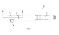
如圖1至圖3中所示,當前公開的實施例中的至少一些包括具有頭部105和從頭部105延伸的手柄110的工具100。頭部105可包括用於容納棘輪部件的腔。可在頭部105內限定袋部115,以容納偏壓構件120,該偏壓構件120適於選擇性地將棘爪中的一個偏壓成與齒輪齒以及工具100的其他機械部件接合。偏壓構件120可包括通過支柱124彼此聯接的第一偏壓部122和第二偏壓部123。例如,第一偏壓部122和第二偏壓部123以及支柱124可彼此成一體。工具100還可包括統稱為球止動機構135的球125和彈簧130。As shown in FIGS. 1-3 , at least some of the presently disclosed embodiments include a
如圖所示,工具100可包括換向杆140,使用者可旋轉換向杆140以選擇性地使工具100沿順時針方向或逆時針方向操作。換向杆140可包括旋鈕142,使用者可抓握旋鈕142以選擇工具100將要施加扭矩的、期望的旋轉方向。換向杆140還可包括接合第一棘爪152與第二棘爪153的鉤部145。例如,根據換向杆140如何旋轉,鉤部145將接合第一棘爪152、第二棘爪153中的一個,並使接合的第一棘爪152隨後接合驅動齒輪155。As shown, the
如圖2B中所示,驅動齒輪155可設置在頭部105內,以向工件施加扭矩。第一棘爪152和第二棘爪153也可設置在頭部105中,以在驅動齒輪155沿驅動旋轉方向旋轉時接合驅動齒輪155,並且在驅動齒淪155沿與驅動旋轉方向相反的滑動旋轉方向旋轉時相對於驅動齒輪155滑動。驅動齒輪155可連接到與套筒聯接的傳動突緣160,傳動突緣160隨後向工件施加扭矩。As shown in Figure 2B, a
工具100包括一種稱為雙棘爪棘輪扳手的棘輪,該棘輪允許使用者選擇性地確定扭矩方向。更具體地,第一棘爪152和第二棘爪153可與驅動齒輪155選擇性地接合,而驅動齒輪155可與工件操作性地接合以向工件施加扭矩。當第一棘爪152與驅動齒輪155接合時,隨著工具100沿第一旋轉驅動方向的旋轉而允許扭矩驅動,而隨著工具100沿與第一旋轉方向相反的第二旋轉方向的旋轉而發生滑動。相反,當第二棘爪153與驅動齒輪155接合時,第一棘爪152脫離與驅動齒輪155的接合,並且隨著工具100沿第二旋轉方向的旋轉而允許扭矩驅動,同時隨著沿第一旋轉方向的旋轉而發生滑動。The
如所描述的,換向杆140配置為選擇第一棘爪152與第二棘爪153中的一個,從而選擇工具100可施加扭矩的旋轉方向。例如,換向杆140的鉤部145中的一個可與第一棘爪152與第二棘爪153中的一個接合,並使接合的第一棘爪152隨後與驅動齒輪155接合。如此,換向杆140將使棘爪中的另一個(第二棘爪153)脫離驅動齒輪155。最終結果是,接合的第一棘爪152將使其齒與驅動齒輪155的齒接合,令接合的第一棘爪152在手柄110沿第一旋轉方向旋轉時(如圖3所示,當手柄110沿順時針方向旋轉時)能夠滑動,並令接合的第一棘爪152能夠抓握驅動齒輪155,以允許沿與第一旋轉方向相反的第二旋轉方向施加扭矩(如圖3所示,當手柄110沿逆時針方向旋轉時)。As depicted, the
如上所述,除非接合的第一棘爪152被偏壓成與驅動齒輪155的齒輪齒接合,否則第一棘爪152與第二棘爪153在接合驅動齒輪155時可發生空轉。因此,當前公開的實施例中的至少一些將偏壓構件120實現為將接合的第一棘爪152偏壓成與驅動齒輪155的齒輪齒接合。例如,當第一棘爪152是接合的棘爪時,第一偏壓部122可接合第一棘爪152,而當第二棘爪153是接合的棘爪時,第二偏壓部123可接合第二棘爪153。圖2B示出了棘爪機構的一個這樣的示例,其中未接合的第二棘爪153沒有被其相應的第二偏壓部123偏壓成接合(狀態)。這裏,第一偏壓部122將第一棘爪152偏壓成與驅動齒輪155接合,以限制棘輪操作中的空轉。如圖所示,偏壓構件120是板簧,但是在一些實施例中,偏壓構件120可以是向第一棘爪152與第二棘爪153施加偏壓的另一種構件。As described above, unless the engaged
如圖2B和圖3中所示,袋部115可包括凹進處165,該凹進處165可設置有支柱124。凹進處165讓支柱124能夠在使用期間保持於工作位置,並讓柔性偏壓構件120能夠在工具100的組裝期間插入。例如,支柱124可以是圓形形狀的,而凹進處165可類似地為圓形形狀的以允許支柱124安裝在其中。為了便於組裝,支柱124在插入凹進處165的過程中可彎曲。通過將支柱124定位在凹進處165中,就不再像傳統的雙棘爪棘輪工具一樣需要單獨的間隔件了。因此,凹進處165可允許結構穩定、緊湊的偏壓構件,該偏壓構件在使用期間向第一棘爪152與第二153施加偏壓力以限制棘輪機構期間的空轉量。As shown in FIGS. 2B and 3 , the
球止動機構135定位在頭部105的袋部115內,並且沿向上的方向朝向換向杆140的底部被偏壓。換向杆140可包括部分球形的凹坑,當換向杆140順時針或逆時針旋轉可允許的量時,所述凹坑接納球125。因此,球125可向使用者提供表明換向杆140已經達到期望的旋轉接合方向的觸覺指示,並且可以進一步將換向杆140阻留在期望的位置。如圖3所示,球止動機構135可設置在頭部105的凹陷部170內,但是球止動機構135也可位於任何位置,只要當達到期望的旋轉接合方向時,該球止動機構135能夠向使用者提供觸覺指示即可。The
如本文中所使用的,術語「聯接」及其功能等同詞不旨在必然限於兩個或更多個部件的直接機械聯接。相反,術語「聯接」及其功能等同詞意在表示兩個或更多個對象、特徵、工件和/或環境物質之間的任意直接或間接的機械、電氣或化學連接。在一些示例中,「聯接」還意在表示一個對象與另一對象形成為一體。As used herein, the term "coupled" and its functional equivalents are not intended to be necessarily limited to direct mechanical coupling of two or more components. Rather, the term "coupled" and its functional equivalents are intended to mean any direct or indirect mechanical, electrical or chemical connection between two or more objects, features, workpieces and/or environmental substances. In some examples, "joined" is also intended to mean that one object forms a unity with another object.
在前面的描述和附圖中闡述的內容僅以說明的方式提供,而不作為限制。儘管已經示出並描述了具體實施例,但是對於本領域技術人員而言將顯而易見的是,在不脫離發明人的貢獻的更廣泛方面的情況下,可以進行改變和修改。當以基於現有技術的他們的合適視角觀察時,所尋求的實際保護範圍旨在限定於以下的申請專利範圍中。What has been set forth in the foregoing description and accompanying drawings is provided by way of illustration only, and not of limitation. While specific embodiments have been shown and described, it will be apparent to those skilled in the art that changes and modifications can be made without departing from the broader aspects of the inventor's contribution. The actual scope of protection sought is intended to be limited to the following claims when viewed in their proper perspective based on the prior art.
100:工具105:頭部110:手柄115:袋部120:偏壓構件122:第一偏壓部123:第二偏壓部124:支柱125:球130:彈簧135:球止動機構140:換向杆142:旋鈕145:鉤部152:第一棘爪153:第二棘爪155:驅動齒輪160:傳動突緣165:凹進處170:凹陷部100: Tools105: Head110: handle115: Bag Department120: Biasing member122: the first bias part123: Second bias part124: Pillar125: Ball130: Spring135: Ball stop mechanism140: Reversing lever142: Knob145: Hook152: The first pawl153: Second pawl155: Drive Gear160: Drive lugs165: Recess170: Depression
出於促進對所要保護的主題的理解的目的,在附圖中示出了其實施例,通過對這些附圖的觀察,當結合以下的描述進行考慮時,要保護的主題及其結構、操作和許多優點應容易被理解和領會。圖1是根據本發明的實施例的工具的俯視透視爆炸圖。圖2 A是根據本發明的實施例的工具的側視圖。圖2B是根據本發明的實施例的、沿著圖2A中的線2B-2B剖切的、工具的俯視剖視圖。圖3是根據本發明的實施例的工具在換向杆被移除的情況下的俯視透視圖。For the purpose of promoting an understanding of the claimed subject matter, embodiments thereof are shown in the accompanying drawings, through observation of these drawings, when considered in conjunction with the following description, the claimed subject matter and its structure, operation and many advantages should be easily understood and appreciated.1 is a top perspective exploded view of a tool according to an embodiment of the present invention.Figure 2A is a side view of a tool according to an embodiment of the present invention.2B is a top cross-sectional view of the tool, taken along
100:工具100: Tools
105:頭部105: Head
110:手柄110: handle
115:袋部115: Bag Department
120:偏壓構件120: Biasing member
122:第一偏壓部122: the first bias part
123:第二偏壓部123: Second bias part
124:支柱124: Pillar
125:球125: Ball
130:彈簧130: Spring
135:球止動機構135: Ball stop mechanism
140:換向杆140: Reversing lever
142:旋鈕142: Knob
145:鉤部145: Hook
Claims (15)
Translated fromChineseApplications Claiming Priority (2)
| Application Number | Priority Date | Filing Date | Title |
|---|---|---|---|
| US16/284,122 | 2019-02-25 | ||
| US16/284,122US20200269392A1 (en) | 2019-02-25 | 2019-02-25 | Tool with double leaf spring |
Publications (2)
| Publication Number | Publication Date |
|---|---|
| TW202031433A TW202031433A (en) | 2020-09-01 |
| TWI772746Btrue TWI772746B (en) | 2022-08-01 |
Family
ID=68207147
Family Applications (1)
| Application Number | Title | Priority Date | Filing Date |
|---|---|---|---|
| TW109104596ATWI772746B (en) | 2019-02-25 | 2020-02-13 | Tool with double leaf spring |
Country Status (6)
| Country | Link |
|---|---|
| US (1) | US20200269392A1 (en) |
| CN (1) | CN111604850B (en) |
| AU (2) | AU2019222858B2 (en) |
| CA (1) | CA3054906C (en) |
| GB (2) | GB2606471B (en) |
| TW (1) | TWI772746B (en) |
Families Citing this family (3)
| Publication number | Priority date | Publication date | Assignee | Title |
|---|---|---|---|---|
| US11865678B2 (en) | 2021-02-02 | 2024-01-09 | Snap-On Incorporated | Dual pawl ratchet mechanism |
| US11986928B2 (en) | 2022-04-14 | 2024-05-21 | Snap-On Incorporated | Pawl mechanism for ratchet tool |
| CN115625663B (en)* | 2022-11-03 | 2025-09-02 | 东莞怡合达自动化股份有限公司 | A handle |
Citations (5)
| Publication number | Priority date | Publication date | Assignee | Title |
|---|---|---|---|---|
| TW547260U (en)* | 2002-12-31 | 2003-08-11 | Guo-Jung Jeng | Improved structure for ratchet wrench |
| US20060065080A1 (en)* | 2004-09-28 | 2006-03-30 | Davidson John B | Ratcheting tools |
| US7299720B1 (en)* | 2006-01-20 | 2007-11-27 | Snap-On Incorporated | Reversible ratchet wrench |
| CN101337343A (en)* | 2007-07-02 | 2009-01-07 | 英发企业股份有限公司 | Wrench with bidirectional control button positioning structure |
| TW201834792A (en)* | 2017-03-22 | 2018-10-01 | 美商施耐寶公司 | Hub for ratchet gears |
Family Cites Families (13)
| Publication number | Priority date | Publication date | Assignee | Title |
|---|---|---|---|---|
| US837537A (en)* | 1906-06-27 | 1906-12-04 | Peter C Beyer | Ratchet-wrench. |
| US1032871A (en)* | 1911-11-25 | 1912-07-16 | Charles A Bancroft | Wrench. |
| GB584232A (en)* | 1944-12-19 | 1947-01-09 | Abingdon King Dick Ltd | Improvements in or relating to reversible ratchet devices for wrenches, spanners andother hand tools |
| US3504579A (en)* | 1967-11-02 | 1970-04-07 | Dwayne L Harlan | Open end ratchet wrench |
| US5467672A (en)* | 1992-04-20 | 1995-11-21 | Ashby; Earl T. | Open end ratchet wrench |
| US5467874A (en)* | 1995-01-10 | 1995-11-21 | Whitaker; Eugene | Ball lock socket holder |
| DE20210730U1 (en)* | 2002-07-16 | 2002-11-14 | Hsien, Chih-Ching, Feng Yuan, Taichung | Ratchet wrench with switch mechanism |
| US20060213334A1 (en)* | 2005-03-28 | 2006-09-28 | Lee Chang C | Ratchet mechanism for ratchet tools |
| US7263918B1 (en)* | 2006-07-05 | 2007-09-04 | Cheng-Tsan Hu | Ratchet structure for a wrench |
| US7987747B2 (en)* | 2007-04-05 | 2011-08-02 | Snap-On Incorporated | Bias assembly for ratchet tools |
| TWI372678B (en)* | 2009-09-18 | 2012-09-21 | Koken Tool | Ratchet wrench handle |
| EP2844432B1 (en)* | 2012-04-30 | 2017-09-13 | Jeffrey Dean Macdonald | Open-ended ratchet wrench |
| US10016880B2 (en)* | 2016-10-10 | 2018-07-10 | Hui-Hsueh Chung | Selectively one-way wrench |
- 2019
- 2019-02-25USUS16/284,122patent/US20200269392A1/enactivePending
- 2019-08-28AUAU2019222858Apatent/AU2019222858B2/enactiveActive
- 2019-09-02GBGB2208824.9Apatent/GB2606471B/enactiveActive
- 2019-09-02GBGB1912583.0Apatent/GB2581548B/enactiveActive
- 2019-09-10CACA3054906Apatent/CA3054906C/enactiveActive
- 2020
- 2020-02-11CNCN202010086584.4Apatent/CN111604850B/enactiveActive
- 2020-02-13TWTW109104596Apatent/TWI772746B/enactive
- 2021
- 2021-06-22AUAU2021204206Apatent/AU2021204206B2/enactiveActive
Patent Citations (5)
| Publication number | Priority date | Publication date | Assignee | Title |
|---|---|---|---|---|
| TW547260U (en)* | 2002-12-31 | 2003-08-11 | Guo-Jung Jeng | Improved structure for ratchet wrench |
| US20060065080A1 (en)* | 2004-09-28 | 2006-03-30 | Davidson John B | Ratcheting tools |
| US7299720B1 (en)* | 2006-01-20 | 2007-11-27 | Snap-On Incorporated | Reversible ratchet wrench |
| CN101337343A (en)* | 2007-07-02 | 2009-01-07 | 英发企业股份有限公司 | Wrench with bidirectional control button positioning structure |
| TW201834792A (en)* | 2017-03-22 | 2018-10-01 | 美商施耐寶公司 | Hub for ratchet gears |
Also Published As
| Publication number | Publication date |
|---|---|
| GB2606471B (en) | 2023-09-27 |
| CA3054906C (en) | 2021-10-26 |
| GB2581548A (en) | 2020-08-26 |
| GB2606471A (en) | 2022-11-09 |
| AU2019222858A1 (en) | 2020-09-10 |
| AU2019222858B2 (en) | 2021-03-25 |
| CN111604850A (en) | 2020-09-01 |
| AU2021204206B2 (en) | 2023-05-04 |
| GB2581548B (en) | 2022-08-03 |
| GB201912583D0 (en) | 2019-10-16 |
| CA3054906A1 (en) | 2020-08-25 |
| US20200269392A1 (en) | 2020-08-27 |
| CN111604850B (en) | 2022-03-22 |
| GB202208824D0 (en) | 2022-07-27 |
| TW202031433A (en) | 2020-09-01 |
| AU2021204206A1 (en) | 2021-07-15 |
Similar Documents
| Publication | Publication Date | Title |
|---|---|---|
| TWI772746B (en) | Tool with double leaf spring | |
| TWI628050B (en) | Ratchet tool including retaining ring | |
| US5957009A (en) | Control mechanism for ratchet wrench | |
| CN106141970A (en) | Open ratchet wrench | |
| US6182536B1 (en) | Hand tool with ratchet handle and associated quick release mechanism | |
| TWI719680B (en) | Ratchet wrench with tube spring | |
| US6059083A (en) | Ratchet mechanism | |
| US20060065080A1 (en) | Ratcheting tools | |
| US20080141833A1 (en) | Ratchet wrench with rotatable head | |
| CN110576408B (en) | Reversing mechanism comprising a reversing lever | |
| US9914201B2 (en) | Ratchet tool device | |
| TWI853526B (en) | Pawl mechanism for ratchet tool and ratchet tool | |
| TWM505378U (en) | Structure of wrench | |
| US6902047B2 (en) | Ratchet device comprising two sets of symmetrical pawls to enhance torsion thereof | |
| HK40026483B (en) | Tool with double leaf spring | |
| HK40026483A (en) | Tool with double leaf spring | |
| TW202045317A (en) | Grooved drive for ratchet tools | |
| US10245712B2 (en) | Ratchet wrench having quick release structure | |
| US12257672B2 (en) | Locking device for tool | |
| HK40075398A (en) | Tool with double leaf spring | |
| TWM528833U (en) | Ratchet wrench with quick release structure | |
| HK40020377A (en) | Ratchet wrench with tube spring | |
| HK40011544A (en) | Reversing lever | |
| HK40011544B (en) | Reversing lever | |
| TWM576089U (en) | Wrench structure |