TWI770571B - Method for reducing measurement interference of micro biosensor - Google Patents
Method for reducing measurement interference of micro biosensorDownload PDFInfo
- Publication number
- TWI770571B TWI770571BTW109126213ATW109126213ATWI770571BTW I770571 BTWI770571 BTW I770571BTW 109126213 ATW109126213 ATW 109126213ATW 109126213 ATW109126213 ATW 109126213ATW I770571 BTWI770571 BTW I770571B
- Authority
- TW
- Taiwan
- Prior art keywords
- sensing segment
- segment
- working electrode
- sensing
- sub
- Prior art date
Links
- 238000005259measurementMethods0.000titleclaimsabstractdescription85
- 238000000034methodMethods0.000titleclaimsabstractdescription40
- 230000009471actionEffects0.000claimsabstractdescription57
- 239000012491analyteSubstances0.000claimsabstractdescription25
- 239000000758substrateSubstances0.000claimsdescription29
- BASFCYQUMIYNBI-UHFFFAOYSA-NplatinumChemical compound[Pt]BASFCYQUMIYNBI-UHFFFAOYSA-N0.000claimsdescription25
- 239000013060biological fluidSubstances0.000claimsdescription23
- 239000003153chemical reaction reagentSubstances0.000claimsdescription16
- 239000000463materialSubstances0.000claimsdescription16
- 230000002452interceptive effectEffects0.000claimsdescription13
- 230000035945sensitivityEffects0.000claimsdescription13
- 239000000126substanceSubstances0.000claimsdescription11
- 229910052697platinumInorganic materials0.000claimsdescription10
- KDLHZDBZIXYQEI-UHFFFAOYSA-NPalladiumChemical compound[Pd]KDLHZDBZIXYQEI-UHFFFAOYSA-N0.000claimsdescription9
- OKTJSMMVPCPJKN-UHFFFAOYSA-NCarbonChemical group[C]OKTJSMMVPCPJKN-UHFFFAOYSA-N0.000claimsdescription8
- 229910052799carbonInorganic materials0.000claimsdescription8
- PCHJSUWPFVWCPO-UHFFFAOYSA-NgoldChemical compound[Au]PCHJSUWPFVWCPO-UHFFFAOYSA-N0.000claimsdescription4
- 229910052737goldInorganic materials0.000claimsdescription4
- 239000010931goldSubstances0.000claimsdescription4
- 229910052741iridiumInorganic materials0.000claimsdescription4
- GKOZUEZYRPOHIO-UHFFFAOYSA-Niridium atomChemical compound[Ir]GKOZUEZYRPOHIO-UHFFFAOYSA-N0.000claimsdescription4
- 229910052763palladiumInorganic materials0.000claimsdescription4
- -1Ir)Chemical compound0.000claimsdescription2
- 239000004020conductorSubstances0.000description59
- RZVAJINKPMORJF-UHFFFAOYSA-NN-acetyl-para-amino-phenolNatural productsCC(=O)NC1=CC=C(O)C=C1RZVAJINKPMORJF-UHFFFAOYSA-N0.000description34
- WQZGKKKJIJFFOK-GASJEMHNSA-NGlucoseNatural productsOC[C@H]1OC(O)[C@H](O)[C@@H](O)[C@@H]1OWQZGKKKJIJFFOK-GASJEMHNSA-N0.000description29
- 239000008103glucoseSubstances0.000description24
- 238000012360testing methodMethods0.000description23
- 229960005489paracetamolDrugs0.000description17
- 239000000047productSubstances0.000description17
- 238000010586diagramMethods0.000description14
- 239000000243solutionSubstances0.000description11
- MHAJPDPJQMAIIY-UHFFFAOYSA-NHydrogen peroxideChemical compoundOOMHAJPDPJQMAIIY-UHFFFAOYSA-N0.000description10
- CIWBSHSKHKDKBQ-JLAZNSOCSA-NAscorbic acidChemical compoundOC[C@H](O)[C@H]1OC(=O)C(O)=C1OCIWBSHSKHKDKBQ-JLAZNSOCSA-N0.000description9
- 230000000052comparative effectEffects0.000description7
- 229940079593drugDrugs0.000description6
- 239000003814drugSubstances0.000description6
- 230000007246mechanismEffects0.000description6
- 238000012544monitoring processMethods0.000description6
- 239000008280bloodSubstances0.000description5
- 210000004369bloodAnatomy0.000description5
- 238000001727in vivoMethods0.000description5
- 235000010323ascorbic acidNutrition0.000description4
- 239000011668ascorbic acidSubstances0.000description4
- 229960005070ascorbic acidDrugs0.000description4
- 238000007254oxidation reactionMethods0.000description4
- 108090000790EnzymesProteins0.000description3
- 102000004190EnzymesHuman genes0.000description3
- LEHOTFFKMJEONL-UHFFFAOYSA-NUric AcidChemical compoundN1C(=O)NC(=O)C2=C1NC(=O)N2LEHOTFFKMJEONL-UHFFFAOYSA-N0.000description3
- TVWHNULVHGKJHS-UHFFFAOYSA-NUric acidNatural productsN1C(=O)NC(=O)C2NC(=O)NC21TVWHNULVHGKJHS-UHFFFAOYSA-N0.000description3
- 239000006227byproductSubstances0.000description3
- LOKCTEFSRHRXRJ-UHFFFAOYSA-Idipotassium trisodium dihydrogen phosphate hydrogen phosphate dichlorideChemical compoundP(=O)(O)(O)[O-].[K+].P(=O)(O)([O-])[O-].[Na+].[Na+].[Cl-].[K+].[Cl-].[Na+]LOKCTEFSRHRXRJ-UHFFFAOYSA-I0.000description3
- 230000009977dual effectEffects0.000description3
- 229940088598enzymeDrugs0.000description3
- 210000003722extracellular fluidAnatomy0.000description3
- 235000019420glucose oxidaseNutrition0.000description3
- 238000000338in vitroMethods0.000description3
- 238000000059patterningMethods0.000description3
- 239000002953phosphate buffered salineSubstances0.000description3
- 229940116269uric acidDrugs0.000description3
- 108010015776Glucose oxidaseProteins0.000description2
- 239000004366Glucose oxidaseSubstances0.000description2
- XEEYBQQBJWHFJM-UHFFFAOYSA-NIronChemical compound[Fe]XEEYBQQBJWHFJM-UHFFFAOYSA-N0.000description2
- GUBGYTABKSRVRQ-QKKXKWKRSA-NLactoseNatural productsOC[C@H]1O[C@@H](O[C@H]2[C@H](O)[C@@H](O)C(O)O[C@@H]2CO)[C@H](O)[C@@H](O)[C@H]1OGUBGYTABKSRVRQ-QKKXKWKRSA-N0.000description2
- 229920000106Liquid crystal polymerPolymers0.000description2
- 239000004977Liquid-crystal polymers (LCPs)Substances0.000description2
- PXHVJJICTQNCMI-UHFFFAOYSA-NNickelChemical compound[Ni]PXHVJJICTQNCMI-UHFFFAOYSA-N0.000description2
- 230000015572biosynthetic processEffects0.000description2
- 239000004205dimethyl polysiloxaneSubstances0.000description2
- 229940116332glucose oxidaseDrugs0.000description2
- 125000002791glucosyl groupChemical groupC1([C@H](O)[C@@H](O)[C@H](O)[C@H](O1)CO)*0.000description2
- 239000003292glueSubstances0.000description2
- 239000008101lactoseSubstances0.000description2
- 238000004519manufacturing processMethods0.000description2
- 229920000435poly(dimethylsiloxane)Polymers0.000description2
- GUBGYTABKSRVRQ-XLOQQCSPSA-NAlpha-LactoseChemical compoundO[C@@H]1[C@@H](O)[C@@H](O)[C@@H](CO)O[C@H]1O[C@@H]1[C@@H](CO)O[C@H](O)[C@H](O)[C@H]1OGUBGYTABKSRVRQ-XLOQQCSPSA-N0.000description1
- 208000017667Chronic DiseaseDiseases0.000description1
- ZZZCUOFIHGPKAK-UHFFFAOYSA-ND-erythro-ascorbic acidNatural productsOCC1OC(=O)C(O)=C1OZZZCUOFIHGPKAK-UHFFFAOYSA-N0.000description1
- PHOQVHQSTUBQQK-SQOUGZDYSA-ND-glucono-1,5-lactoneChemical compoundOC[C@H]1OC(=O)[C@H](O)[C@@H](O)[C@@H]1OPHOQVHQSTUBQQK-SQOUGZDYSA-N0.000description1
- LFQSCWFLJHTTHZ-UHFFFAOYSA-NEthanolChemical compoundCCOLFQSCWFLJHTTHZ-UHFFFAOYSA-N0.000description1
- GYHNNYVSQQEPJS-UHFFFAOYSA-NGalliumChemical compound[Ga]GYHNNYVSQQEPJS-UHFFFAOYSA-N0.000description1
- FYYHWMGAXLPEAU-UHFFFAOYSA-NMagnesiumChemical compound[Mg]FYYHWMGAXLPEAU-UHFFFAOYSA-N0.000description1
- ZOKXTWBITQBERF-UHFFFAOYSA-NMolybdenumChemical compound[Mo]ZOKXTWBITQBERF-UHFFFAOYSA-N0.000description1
- 239000004642PolyimideSubstances0.000description1
- 229920001486SU-8 photoresistPolymers0.000description1
- BQCADISMDOOEFD-UHFFFAOYSA-NSilverChemical compound[Ag]BQCADISMDOOEFD-UHFFFAOYSA-N0.000description1
- ATJFFYVFTNAWJD-UHFFFAOYSA-NTinChemical compound[Sn]ATJFFYVFTNAWJD-UHFFFAOYSA-N0.000description1
- RTAQQCXQSZGOHL-UHFFFAOYSA-NTitaniumChemical compound[Ti]RTAQQCXQSZGOHL-UHFFFAOYSA-N0.000description1
- 229930003268Vitamin CNatural products0.000description1
- HCHKCACWOHOZIP-UHFFFAOYSA-NZincChemical compound[Zn]HCHKCACWOHOZIP-UHFFFAOYSA-N0.000description1
- QCWXUUIWCKQGHC-UHFFFAOYSA-NZirconiumChemical compound[Zr]QCWXUUIWCKQGHC-UHFFFAOYSA-N0.000description1
- 229910045601alloyInorganic materials0.000description1
- 239000000956alloySubstances0.000description1
- 229910052782aluminiumInorganic materials0.000description1
- XAGFODPZIPBFFR-UHFFFAOYSA-NaluminiumChemical compound[Al]XAGFODPZIPBFFR-UHFFFAOYSA-N0.000description1
- QVGXLLKOCUKJST-UHFFFAOYSA-Natomic oxygenChemical compound[O]QVGXLLKOCUKJST-UHFFFAOYSA-N0.000description1
- WQZGKKKJIJFFOK-VFUOTHLCSA-Nbeta-D-glucoseChemical compoundOC[C@H]1O[C@@H](O)[C@H](O)[C@@H](O)[C@@H]1OWQZGKKKJIJFFOK-VFUOTHLCSA-N0.000description1
- 238000010241blood samplingMethods0.000description1
- 238000006243chemical reactionMethods0.000description1
- 238000001514detection methodMethods0.000description1
- 206010012601diabetes mellitusDiseases0.000description1
- 238000003745diagnosisMethods0.000description1
- 238000005553drillingMethods0.000description1
- 230000000694effectsEffects0.000description1
- 230000005611electricityEffects0.000description1
- 238000002848electrochemical methodMethods0.000description1
- 238000003487electrochemical reactionMethods0.000description1
- 229910052733galliumInorganic materials0.000description1
- 235000012209glucono delta-lactoneNutrition0.000description1
- 229960003681gluconolactoneDrugs0.000description1
- 150000002303glucose derivativesChemical class0.000description1
- 238000007654immersionMethods0.000description1
- 229910052738indiumInorganic materials0.000description1
- APFVFJFRJDLVQX-UHFFFAOYSA-Nindium atomChemical compound[In]APFVFJFRJDLVQX-UHFFFAOYSA-N0.000description1
- 238000009413insulationMethods0.000description1
- 239000012212insulatorSubstances0.000description1
- 239000000543intermediateSubstances0.000description1
- 229910052742ironInorganic materials0.000description1
- 239000011133leadSubstances0.000description1
- 229910052749magnesiumInorganic materials0.000description1
- 239000011777magnesiumSubstances0.000description1
- 150000002736metal compoundsChemical class0.000description1
- 229910052750molybdenumInorganic materials0.000description1
- 239000011733molybdenumSubstances0.000description1
- 229910052759nickelInorganic materials0.000description1
- 229910052762osmiumInorganic materials0.000description1
- SYQBFIAQOQZEGI-UHFFFAOYSA-Nosmium atomChemical compound[Os]SYQBFIAQOQZEGI-UHFFFAOYSA-N0.000description1
- 230000003647oxidationEffects0.000description1
- 239000001301oxygenSubstances0.000description1
- 229910052760oxygenInorganic materials0.000description1
- 229940124641pain relieverDrugs0.000description1
- 229940072647panadolDrugs0.000description1
- 230000002093peripheral effectEffects0.000description1
- 229920000052poly(p-xylylene)Polymers0.000description1
- 229920001721polyimidePolymers0.000description1
- 230000008569processEffects0.000description1
- 108090000623proteins and genesProteins0.000description1
- 102000004169proteins and genesHuman genes0.000description1
- 230000035484reaction timeEffects0.000description1
- 230000009257reactivityEffects0.000description1
- 230000004044responseEffects0.000description1
- 238000012552reviewMethods0.000description1
- 229910052703rhodiumInorganic materials0.000description1
- 239000010948rhodiumSubstances0.000description1
- MHOVAHRLVXNVSD-UHFFFAOYSA-Nrhodium atomChemical compound[Rh]MHOVAHRLVXNVSD-UHFFFAOYSA-N0.000description1
- 229910052710siliconInorganic materials0.000description1
- 239000010703siliconSubstances0.000description1
- 229910052709silverInorganic materials0.000description1
- 239000004332silverSubstances0.000description1
- 229910052718tinInorganic materials0.000description1
- 239000011135tinSubstances0.000description1
- 229910052719titaniumInorganic materials0.000description1
- 239000010936titaniumSubstances0.000description1
- 238000012546transferMethods0.000description1
- 235000019154vitamin CNutrition0.000description1
- 239000011718vitamin CSubstances0.000description1
- 229910052725zincInorganic materials0.000description1
- 239000011701zincSubstances0.000description1
- 229910052726zirconiumInorganic materials0.000description1
Images


Classifications
- A—HUMAN NECESSITIES
- A61—MEDICAL OR VETERINARY SCIENCE; HYGIENE
- A61B—DIAGNOSIS; SURGERY; IDENTIFICATION
- A61B5/00—Measuring for diagnostic purposes; Identification of persons
- A61B5/145—Measuring characteristics of blood in vivo, e.g. gas concentration or pH-value ; Measuring characteristics of body fluids or tissues, e.g. interstitial fluid or cerebral tissue
- A61B5/14532—Measuring characteristics of blood in vivo, e.g. gas concentration or pH-value ; Measuring characteristics of body fluids or tissues, e.g. interstitial fluid or cerebral tissue for measuring glucose, e.g. by tissue impedance measurement
- G—PHYSICS
- G01—MEASURING; TESTING
- G01N—INVESTIGATING OR ANALYSING MATERIALS BY DETERMINING THEIR CHEMICAL OR PHYSICAL PROPERTIES
- G01N27/00—Investigating or analysing materials by the use of electric, electrochemical, or magnetic means
- G01N27/26—Investigating or analysing materials by the use of electric, electrochemical, or magnetic means by investigating electrochemical variables; by using electrolysis or electrophoresis
- G01N27/28—Electrolytic cell components
- G01N27/30—Electrodes, e.g. test electrodes; Half-cells
- G01N27/327—Biochemical electrodes, e.g. electrical or mechanical details for in vitro measurements
- G01N27/3271—Amperometric enzyme electrodes for analytes in body fluids, e.g. glucose in blood
- A—HUMAN NECESSITIES
- A61—MEDICAL OR VETERINARY SCIENCE; HYGIENE
- A61B—DIAGNOSIS; SURGERY; IDENTIFICATION
- A61B5/00—Measuring for diagnostic purposes; Identification of persons
- A61B5/145—Measuring characteristics of blood in vivo, e.g. gas concentration or pH-value ; Measuring characteristics of body fluids or tissues, e.g. interstitial fluid or cerebral tissue
- A61B5/14503—Measuring characteristics of blood in vivo, e.g. gas concentration or pH-value ; Measuring characteristics of body fluids or tissues, e.g. interstitial fluid or cerebral tissue invasive, e.g. introduced into the body by a catheter or needle or using implanted sensors
- A—HUMAN NECESSITIES
- A61—MEDICAL OR VETERINARY SCIENCE; HYGIENE
- A61B—DIAGNOSIS; SURGERY; IDENTIFICATION
- A61B5/00—Measuring for diagnostic purposes; Identification of persons
- A61B5/145—Measuring characteristics of blood in vivo, e.g. gas concentration or pH-value ; Measuring characteristics of body fluids or tissues, e.g. interstitial fluid or cerebral tissue
- A61B5/14507—Measuring characteristics of blood in vivo, e.g. gas concentration or pH-value ; Measuring characteristics of body fluids or tissues, e.g. interstitial fluid or cerebral tissue specially adapted for measuring characteristics of body fluids other than blood
- A61B5/1451—Measuring characteristics of blood in vivo, e.g. gas concentration or pH-value ; Measuring characteristics of body fluids or tissues, e.g. interstitial fluid or cerebral tissue specially adapted for measuring characteristics of body fluids other than blood for interstitial fluid
- A—HUMAN NECESSITIES
- A61—MEDICAL OR VETERINARY SCIENCE; HYGIENE
- A61B—DIAGNOSIS; SURGERY; IDENTIFICATION
- A61B5/00—Measuring for diagnostic purposes; Identification of persons
- A61B5/145—Measuring characteristics of blood in vivo, e.g. gas concentration or pH-value ; Measuring characteristics of body fluids or tissues, e.g. interstitial fluid or cerebral tissue
- A61B5/14546—Measuring characteristics of blood in vivo, e.g. gas concentration or pH-value ; Measuring characteristics of body fluids or tissues, e.g. interstitial fluid or cerebral tissue for measuring analytes not otherwise provided for, e.g. ions, cytochromes
- A—HUMAN NECESSITIES
- A61—MEDICAL OR VETERINARY SCIENCE; HYGIENE
- A61B—DIAGNOSIS; SURGERY; IDENTIFICATION
- A61B5/00—Measuring for diagnostic purposes; Identification of persons
- A61B5/145—Measuring characteristics of blood in vivo, e.g. gas concentration or pH-value ; Measuring characteristics of body fluids or tissues, e.g. interstitial fluid or cerebral tissue
- A61B5/1468—Measuring characteristics of blood in vivo, e.g. gas concentration or pH-value ; Measuring characteristics of body fluids or tissues, e.g. interstitial fluid or cerebral tissue using chemical or electrochemical methods, e.g. by polarographic means
- A61B5/1473—Measuring characteristics of blood in vivo, e.g. gas concentration or pH-value ; Measuring characteristics of body fluids or tissues, e.g. interstitial fluid or cerebral tissue using chemical or electrochemical methods, e.g. by polarographic means invasive, e.g. introduced into the body by a catheter
- A61B5/14735—Measuring characteristics of blood in vivo, e.g. gas concentration or pH-value ; Measuring characteristics of body fluids or tissues, e.g. interstitial fluid or cerebral tissue using chemical or electrochemical methods, e.g. by polarographic means invasive, e.g. introduced into the body by a catheter comprising an immobilised reagent
- A—HUMAN NECESSITIES
- A61—MEDICAL OR VETERINARY SCIENCE; HYGIENE
- A61B—DIAGNOSIS; SURGERY; IDENTIFICATION
- A61B5/00—Measuring for diagnostic purposes; Identification of persons
- A61B5/145—Measuring characteristics of blood in vivo, e.g. gas concentration or pH-value ; Measuring characteristics of body fluids or tissues, e.g. interstitial fluid or cerebral tissue
- A61B5/1468—Measuring characteristics of blood in vivo, e.g. gas concentration or pH-value ; Measuring characteristics of body fluids or tissues, e.g. interstitial fluid or cerebral tissue using chemical or electrochemical methods, e.g. by polarographic means
- A61B5/1486—Measuring characteristics of blood in vivo, e.g. gas concentration or pH-value ; Measuring characteristics of body fluids or tissues, e.g. interstitial fluid or cerebral tissue using chemical or electrochemical methods, e.g. by polarographic means using enzyme electrodes, e.g. with immobilised oxidase
- A61B5/14865—Measuring characteristics of blood in vivo, e.g. gas concentration or pH-value ; Measuring characteristics of body fluids or tissues, e.g. interstitial fluid or cerebral tissue using chemical or electrochemical methods, e.g. by polarographic means using enzyme electrodes, e.g. with immobilised oxidase invasive, e.g. introduced into the body by a catheter or needle or using implanted sensors
- A—HUMAN NECESSITIES
- A61—MEDICAL OR VETERINARY SCIENCE; HYGIENE
- A61B—DIAGNOSIS; SURGERY; IDENTIFICATION
- A61B5/00—Measuring for diagnostic purposes; Identification of persons
- A61B5/68—Arrangements of detecting, measuring or recording means, e.g. sensors, in relation to patient
- A61B5/6846—Arrangements of detecting, measuring or recording means, e.g. sensors, in relation to patient specially adapted to be brought in contact with an internal body part, i.e. invasive
- A61B5/6847—Arrangements of detecting, measuring or recording means, e.g. sensors, in relation to patient specially adapted to be brought in contact with an internal body part, i.e. invasive mounted on an invasive device
- A61B5/686—Permanently implanted devices, e.g. pacemakers, other stimulators, biochips
- G—PHYSICS
- G01—MEASURING; TESTING
- G01N—INVESTIGATING OR ANALYSING MATERIALS BY DETERMINING THEIR CHEMICAL OR PHYSICAL PROPERTIES
- G01N27/00—Investigating or analysing materials by the use of electric, electrochemical, or magnetic means
- G01N27/26—Investigating or analysing materials by the use of electric, electrochemical, or magnetic means by investigating electrochemical variables; by using electrolysis or electrophoresis
- G01N27/28—Electrolytic cell components
- G01N27/30—Electrodes, e.g. test electrodes; Half-cells
- G01N27/327—Biochemical electrodes, e.g. electrical or mechanical details for in vitro measurements
- G01N27/3275—Sensing specific biomolecules, e.g. nucleic acid strands, based on an electrode surface reaction
- G01N27/3278—Sensing specific biomolecules, e.g. nucleic acid strands, based on an electrode surface reaction involving nanosized elements, e.g. nanogaps or nanoparticles
- A—HUMAN NECESSITIES
- A61—MEDICAL OR VETERINARY SCIENCE; HYGIENE
- A61B—DIAGNOSIS; SURGERY; IDENTIFICATION
- A61B2560/00—Constructional details of operational features of apparatus; Accessories for medical measuring apparatus
- A61B2560/02—Operational features
- A61B2560/0223—Operational features of calibration, e.g. protocols for calibrating sensors
- A—HUMAN NECESSITIES
- A61—MEDICAL OR VETERINARY SCIENCE; HYGIENE
- A61B—DIAGNOSIS; SURGERY; IDENTIFICATION
- A61B2560/00—Constructional details of operational features of apparatus; Accessories for medical measuring apparatus
- A61B2560/04—Constructional details of apparatus
- A61B2560/0462—Apparatus with built-in sensors
- A61B2560/0468—Built-in electrodes
- A—HUMAN NECESSITIES
- A61—MEDICAL OR VETERINARY SCIENCE; HYGIENE
- A61B—DIAGNOSIS; SURGERY; IDENTIFICATION
- A61B2562/00—Details of sensors; Constructional details of sensor housings or probes; Accessories for sensors
- A61B2562/02—Details of sensors specially adapted for in-vivo measurements
- A—HUMAN NECESSITIES
- A61—MEDICAL OR VETERINARY SCIENCE; HYGIENE
- A61B—DIAGNOSIS; SURGERY; IDENTIFICATION
- A61B2562/00—Details of sensors; Constructional details of sensor housings or probes; Accessories for sensors
- A61B2562/02—Details of sensors specially adapted for in-vivo measurements
- A61B2562/0209—Special features of electrodes classified in A61B5/24, A61B5/25, A61B5/283, A61B5/291, A61B5/296, A61B5/053
- A61B2562/0215—Silver or silver chloride containing
- A—HUMAN NECESSITIES
- A61—MEDICAL OR VETERINARY SCIENCE; HYGIENE
- A61B—DIAGNOSIS; SURGERY; IDENTIFICATION
- A61B2562/00—Details of sensors; Constructional details of sensor housings or probes; Accessories for sensors
- A61B2562/02—Details of sensors specially adapted for in-vivo measurements
- A61B2562/0209—Special features of electrodes classified in A61B5/24, A61B5/25, A61B5/283, A61B5/291, A61B5/296, A61B5/053
- A61B2562/0217—Electrolyte containing
- A—HUMAN NECESSITIES
- A61—MEDICAL OR VETERINARY SCIENCE; HYGIENE
- A61B—DIAGNOSIS; SURGERY; IDENTIFICATION
- A61B2562/00—Details of sensors; Constructional details of sensor housings or probes; Accessories for sensors
- A61B2562/02—Details of sensors specially adapted for in-vivo measurements
- A61B2562/028—Microscale sensors, e.g. electromechanical sensors [MEMS]
- A—HUMAN NECESSITIES
- A61—MEDICAL OR VETERINARY SCIENCE; HYGIENE
- A61B—DIAGNOSIS; SURGERY; IDENTIFICATION
- A61B2562/00—Details of sensors; Constructional details of sensor housings or probes; Accessories for sensors
- A61B2562/12—Manufacturing methods specially adapted for producing sensors for in-vivo measurements
- A61B2562/125—Manufacturing methods specially adapted for producing sensors for in-vivo measurements characterised by the manufacture of electrodes
- A—HUMAN NECESSITIES
- A61—MEDICAL OR VETERINARY SCIENCE; HYGIENE
- A61B—DIAGNOSIS; SURGERY; IDENTIFICATION
- A61B2562/00—Details of sensors; Constructional details of sensor housings or probes; Accessories for sensors
- A61B2562/16—Details of sensor housings or probes; Details of structural supports for sensors
- A—HUMAN NECESSITIES
- A61—MEDICAL OR VETERINARY SCIENCE; HYGIENE
- A61B—DIAGNOSIS; SURGERY; IDENTIFICATION
- A61B2562/00—Details of sensors; Constructional details of sensor housings or probes; Accessories for sensors
- A61B2562/18—Shielding or protection of sensors from environmental influences, e.g. protection from mechanical damage
- G—PHYSICS
- G01—MEASURING; TESTING
- G01N—INVESTIGATING OR ANALYSING MATERIALS BY DETERMINING THEIR CHEMICAL OR PHYSICAL PROPERTIES
- G01N2800/00—Detection or diagnosis of diseases
- G01N2800/04—Endocrine or metabolic disorders
- G01N2800/042—Disorders of carbohydrate metabolism, e.g. diabetes, glucose metabolism
Landscapes
- Health & Medical Sciences (AREA)
- Life Sciences & Earth Sciences (AREA)
- Physics & Mathematics (AREA)
- Molecular Biology (AREA)
- General Health & Medical Sciences (AREA)
- Pathology (AREA)
- Engineering & Computer Science (AREA)
- Biophysics (AREA)
- Biomedical Technology (AREA)
- Heart & Thoracic Surgery (AREA)
- Medical Informatics (AREA)
- Surgery (AREA)
- Animal Behavior & Ethology (AREA)
- Public Health (AREA)
- Veterinary Medicine (AREA)
- Optics & Photonics (AREA)
- Chemical & Material Sciences (AREA)
- Chemical Kinetics & Catalysis (AREA)
- General Chemical & Material Sciences (AREA)
- Emergency Medicine (AREA)
- Immunology (AREA)
- Analytical Chemistry (AREA)
- Biochemistry (AREA)
- Electrochemistry (AREA)
- General Physics & Mathematics (AREA)
- Spectroscopy & Molecular Physics (AREA)
- Hematology (AREA)
- Nanotechnology (AREA)
- Measurement Of The Respiration, Hearing Ability, Form, And Blood Characteristics Of Living Organisms (AREA)
- Organic Chemistry (AREA)
- Proteomics, Peptides & Aminoacids (AREA)
- Wood Science & Technology (AREA)
- Zoology (AREA)
- Measuring Or Testing Involving Enzymes Or Micro-Organisms (AREA)
- Apparatus Associated With Microorganisms And Enzymes (AREA)
- Investigating Or Analysing Biological Materials (AREA)
- Microbiology (AREA)
- General Engineering & Computer Science (AREA)
- Genetics & Genomics (AREA)
- Bioinformatics & Cheminformatics (AREA)
Abstract
Description
Translated fromChinese本發明關於一種微型生物感測器,特別關於一種用於在量測生物流體中的目標分析物時可以降低量測干擾的微型生物感測器及其降低量測干擾的方法。The present invention relates to a miniature biosensor, and more particularly, to a miniature biosensor which can reduce measurement interference when measuring a target analyte in a biological fluid and a method for reducing measurement interference.
基於慢性病患人口快速增長,生物體內生物流體中分析物的檢測對於患者的診斷和監測非常重要,尤其是體內葡萄糖濃度的有效監測更是治療糖尿病的關鍵。因此,近年來連續式葡萄糖監測(continuous glucose monitoring,CGM)系統愈發受重視,該系統具有許多相較於傳統生物感測器的優點,如降低手指血液取樣時的疼痛及連續監測生物流體中一個或多個目標分析物的生理參數。Based on the rapid growth of the population of chronic disease patients, the detection of analytes in biological fluids in vivo is very important for the diagnosis and monitoring of patients, especially the effective monitoring of glucose concentration in vivo is the key to the treatment of diabetes. Therefore, in recent years, continuous glucose monitoring (CGM) system has been paid more and more attention, which has many advantages over traditional biosensors, such as reducing pain during finger blood sampling and continuous monitoring of biological fluids. Physiological parameters of one or more target analytes.
連續式葡萄糖監控系統中包含基於醇的生物感測器,其用以量測體內對應於葡萄糖濃度的生理訊號,且大多運用電化學方式,即以葡萄糖氧化酵素(glucose oxidase,GOx)催化葡萄糖反應生成葡萄糖酸內酯(Gluconolactone)與還原態酵素,後續還原態酵素將與體內生物流體中的氧氣進行電子轉移進而生成副產物過氧化氫(H2O2),最後藉由催化副產物H2O2的氧化反應來量化葡萄糖濃度。然而,血液或組織液中若存在如維他命C的主要成分-抗壞血酸(Ascorbic Acid,AA)、常見止痛藥成分-乙醯胺酚(Acetaminophen,AM)、尿酸(Uric Acid,UA)、蛋白質或葡萄糖類似物等干擾物且其氧化電位接近H2O2的氧化電位時會產生與目標分析物無關的電化學訊號。這樣的干擾訊號必須降低,使生理參數的量測是準確的。The continuous glucose monitoring system includes an alcohol-based biosensor, which is used to measure the physiological signal corresponding to the glucose concentration in the body, and most of them use an electrochemical method, that is, glucose oxidase (glucose oxidase, GOx) catalyzes the glucose reaction Gluconolactone and reduced enzyme are generated, and the subsequent reduced enzyme will transfer electrons with oxygen in the biological fluid in the body to generate by-product hydrogen peroxide (H2 O2 ), and finally catalyze the by-product H2Oxidation reaction to quantify glucose concentration. However, if there are interferences such as the main component of vitamin C - ascorbic acid (AA), common pain reliever components - acetaminophen (AM), uric acid (Uric Acid, UA), protein or glucose analogs, etc. When the oxidation potential is close to that of H2 O2 , an electrochemical signal independent of the target analyte is generated. Such interference signals must be reduced so that the measurement of physiological parameters is accurate.
本發明的微型生物感測器可以植入生物體皮下,用以量測生物流體中目標分析物的生理參數,且本發明的微型生物感測器中包括由不同導電材料組成的兩個工作電極,其中一個工作電極可以消耗生物流體中對量測有影響的干擾物,使另一個工作電極在量測時可得到更準確的量測結果。The micro biosensor of the present invention can be implanted subcutaneously in a living body to measure the physiological parameters of the target analyte in the biological fluid, and the micro biosensor of the present invention includes two working electrodes composed of different conductive materials , one of the working electrodes can consume the interfering substances that affect the measurement in the biological fluid, so that the other working electrode can obtain more accurate measurement results during measurement.
因此,本發明提供一種降低目標分析物量測干擾的方法,配合一微型生物感測器進行,該微型生物感測器用於於一期間內進行一生物流體中一目標分析物的一生理參數的量測,且該期間包含至少一第一子時間(T1)區段與至少一第二子時間(T2)區段,該方法包括:(a)提供該微型生物感測器,該微型生物感測器至少包含一第一工作電極、至少一第二工作電極與一化學試劑,其中該第一工作電極具有一第一感測段,該第二工作電極具有一第二感測段,且該化學試劑至少覆蓋部分該第一感測段,以與該生物流體中的該目標分析物反應而產生一生成物;(b)於一該第一子時間(T1)區段內執行一去干擾動作,使該第二感測段經一第二工作電壓驅動而消耗該生物流體中至少一干擾物;(c)於一該第二子時間(T2)區段內執行一量測動作,使該第一感測段經一第一工作電壓驅動而與該生成物反應以輸出對應該生理參數的一第一生理訊號;(d)於另一該第一子時間(T1)區段內執行另一該去干擾動作,使該第二感測段經該第二工作電壓驅動而消耗該至少一干擾物;(e)於另一該第二子時間(T2)區段內執行另一該量測動作,使該第一感測段經該第一工作電壓驅動而與該生成物反應以輸出對應該生理參數的一第二生理訊號;以及(f)持續循環執行該步驟(b)至該步驟(e),以獲得該生理參數於該期間中不同的該些第二子時間(T2)區段內的表現。Therefore, the present invention provides a method for reducing interference in the measurement of a target analyte, which is performed in conjunction with a micro biosensor for measuring a physiological parameter of a target analyte in a biological fluid within a period of time. Measuring, and the period includes at least a first sub-time (T1) segment and at least a second sub-time (T2) segment, the method includes: (a) providing the micro biosensor, the micro biosensor The detector at least includes a first working electrode, at least a second working electrode and a chemical reagent, wherein the first working electrode has a first sensing segment, the second working electrode has a second sensing segment, and the Chemical reagents cover at least part of the first sensing section to react with the target analyte in the biological fluid to generate a product; (b) perform a de-interference in a section of the first sub-time (T1) act, so that the second sensing segment is driven by a second working voltage to consume at least one disturbance in the biological fluid(c) performing a measurement operation in the second sub-time (T2) section, so that the first sensing segment is driven by a first working voltage to react with the product to output the corresponding physiological parameter a first physiological signal of the an interferer; (e) performing another measurement operation in another second sub-time (T2) section, so that the first sensing segment is driven by the first operating voltage to react with the product to outputting a second physiological signal corresponding to the physiological parameter; and (f) continuously and cyclically executing the steps (b) to (e) to obtain the different second sub-times (T2) of the physiological parameter during the period ) performance within the segment.
本發明另提出一種降低目標分析物量測干擾的方法,配合一微型生物感測器進行,該微型生物感測器用於於一期間內進行一生物流體中一目標分析物的一生理參數的量測,該方法包括:(a)提供該微型生物感測器,該微型生物感測器至少包含一第一工作電極、至少一第二工作電極與一化學試劑,其中該第一工作電極具有一第一感測段,該第二工作電極具有一第二感測段,且該化學試劑至少覆蓋部分該第一感測段,以與該生物流體中的該目標分析物反應而產生一生成物;(b)於該期間內執行一去干擾動作,使該第二感測段經一第二工作電壓驅動而消耗該生物流體中至少一干擾物直至該期間結束;(c)於該期間內的至少一子時間區段內執行一量測動作,使該第一感測段經一第一工作電壓驅動而與該生成物反應以輸出對應該生理參數的一第一生理訊號;(d)於該期間內的另一該子時間區段內執行另一該量測動作,使該第一感測段經該第一工作電壓驅動而與該生成物反應以輸出對應該生理參數的一第二生理訊號;以及(e)持續循環執行該步驟(c)至該步驟(d),以獲得該生理參數於該期間中不同的該些子時間區段內的表現。The present invention further provides a method for reducing the interference of target analyte measurement, which is performed in conjunction with a micro biosensor for measuring the amount of a physiological parameter of a target analyte in a biological fluid within a period of time. The method includes: (a) providing the miniature biosensor, the miniature biosensor comprising at least a first working electrode, at least a second working electrode and a chemical reagent, wherein the first working electrode has a a first sensing segment, the second working electrode has a second sensing segment, and the chemical reagent covers at least part of the first sensing segment to react with the target analyte in the biological fluid to generate a product ; (b) perform a de-interference action during the period, so that the second sensing segment is driven by a second operating voltage to consume at least one interferer in the biological fluid until the period ends; (c) during the period Executes a measurement action within at least a sub-time period of the first sensing segment, so that the first sensing segment is driven by a first working voltage to react with the product to output a first physiological signal corresponding to the physiological parameter; (d) Performing another measurement operation in another sub-time during the period, so that the first sensing segment is driven by the first working voltage to react with the product to output a first corresponding to the
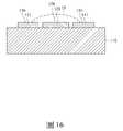
10:微型生物感測器10: Tiny Biosensors
110:基板110: Substrate
111:表面111: Surface
112:對側表面112: Opposite side surface
113:第一端113: First End
114:第二端114: Second End
115:訊號輸出區域115: Signal output area
116:感測區域116: Sensing area
117:絕緣區域117: Insulation area
118:孔洞118: Hole
120:第一工作電極120: The first working electrode
121:第一感測段121: The first sensing segment
122:第一訊號輸出段122: The first signal output section
123:第一訊號連接段123: The first signal connection segment
130:第二工作電極130: Second working electrode
131:第二感測段131: Second sensing segment
132:第二訊號輸出段132: The second signal output section
133:第二訊號連接段133: Second signal connection segment
140:絕緣膠140: Insulating glue
150:化學試劑層150: chemical reagent layer
160:對電極160: Counter electrode
170:參考電極170: Reference electrode
S101-S103:步驟S101-S103: Steps
1C:第一導電材料1C: First Conductive Material
2C:第二導電材料2C: Second Conductive Material
1S:量測範圍1S: Measuring range
2S:去干擾範圍2S: De-interference range
本發明的上述目的及優點在參閱以下詳細說明及附隨圖式之後對那些所屬技術領域中具有通常知識者將變得更立即地顯而易見。The above objects and advantages of the present invention will become more immediately apparent to those of ordinary skill in the art upon review of the following detailed description and accompanying drawings.
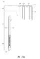
〔圖1(A)〕為本發明的微型生物感測器的第一實施例的正面示意圖。[FIG. 1(A)] is a schematic front view of the first embodiment of the micro biosensor of the present invention.
〔圖1(B)〕為本發明的微型生物感測器的第一實施例的第一工作電極及第二工作電極的配置示意圖。[FIG. 1(B)] is a schematic diagram of the configuration of the first working electrode and the second working electrode of the first embodiment of the micro biosensor of the present invention.
〔圖2(A)〕為本發明圖1(A)中沿A-A’線的剖面示意圖。[Fig. 2(A)] is a schematic cross-sectional view taken along the line A-A' in Fig. 1(A) of the present invention.
〔圖2(B)〕為本發明圖1(A)中沿B-B’線的剖面示意圖。[Fig. 2(B)] is a schematic cross-sectional view taken along the line B-B' in Fig. 1(A) of the present invention.
〔圖2(C)〕為本發明圖1(A)中沿C-C’線的剖面示意圖。[Fig. 2(C)] is a schematic cross-sectional view taken along the line C-C' in Fig. 1(A) of the present invention.
〔圖2(D)〕為本發明以另一製程得到的微型生物感測器的感測區域的剖面示意圖。[FIG. 2(D)] is a schematic cross-sectional view of the sensing area of the micro biosensor obtained by another process of the present invention.
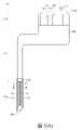
〔圖3(A)〕為本發明的微型生物感測器的第二實施例的正面示意圖。[FIG. 3(A)] is a schematic front view of the second embodiment of the micro biosensor of the present invention.
〔圖3(B)〕為本發明的微型生物感測器的第二實施例的第一工作電極及第二工作電極的配置示意圖。[FIG. 3(B)] is a schematic diagram of the configuration of the first working electrode and the second working electrode of the second embodiment of the micro biosensor of the present invention.
〔圖4〕為本發明圖3(A)中沿A-A’線的剖面示意圖。[Fig. 4] is a schematic cross-sectional view taken along the line A-A' in Fig. 3(A) of the present invention.
〔圖5(A)〕為本發明的微型生物感測器的第三實施例的正面示意圖。[FIG. 5(A)] is a schematic front view of the third embodiment of the micro biosensor of the present invention.
〔圖5(B)〕為本發明圖5(A)中沿A-A’線的剖面示意圖。[Fig. 5(B)] is a schematic cross-sectional view taken along the line A-A' in Fig. 5(A) of the present invention.
〔圖6(A)-6(C)〕為本發明的第一感測段及第二感測段的其他配置方式的示意圖。[FIG. 6(A)-6(C)] are schematic diagrams of other configuration manners of the first sensing segment and the second sensing segment of the present invention.
〔圖6(D)〕為圖6(C)中沿I-I’線的剖面示意圖。[Fig. 6(D)] is a schematic cross-sectional view taken along the line I-I' in Fig. 6(C).
〔圖7〕為本發明的第一感測段及第二感測段的其他配置方式的示意圖。[ FIG. 7 ] is a schematic diagram of other configuration manners of the first sensing segment and the second sensing segment of the present invention.
〔圖8(A)-8(C)〕為本發明的第一感測段及第二感測段的其他配置方式的示意圖。[FIG. 8(A)-8(C)] are schematic diagrams of other configuration manners of the first sensing segment and the second sensing segment of the present invention.
〔圖9(A)〕為本發明的微型生物感測器的感測區域的剖面示意圖。[FIG. 9(A)] is a schematic cross-sectional view of the sensing area of the micro biosensor of the present invention.
〔圖9(B)〕為本發明的微型生物感測器的感測區域的剖面示意圖。[FIG. 9(B)] is a schematic cross-sectional view of the sensing area of the micro biosensor of the present invention.
〔圖10〕為本發明的微型生物感測器經驅動後第一感測段的量測範圍及第二感測段的去干擾範圍的示意圖。[ FIG. 10 ] is a schematic diagram of the measurement range of the first sensing segment and the interference removal range of the second sensing segment after the miniature biosensor of the present invention is driven.
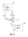
〔圖11〕為控制本發明的微型生物感測器的電壓並測量電流的電路的示意圖。[ FIG. 11 ] is a schematic diagram of a circuit for controlling the voltage of the micro biosensor of the present invention and measuring the current.
〔圖12〕為本發明降低微型生物感測器進行量測時所產生的干擾的方法流程圖。[FIG. 12] is a flow chart of the method of the present invention for reducing the interference generated by the micro biosensor during measurement.
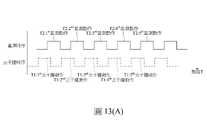
〔圖13(A)-13(C)〕為本發明降低微型生物感測器進行量測時,去干擾動作與量測動作之間的時間關係示意圖,其中圖13(A)為去干擾動作與量測動作部分重疊,圖13(B)為去干擾動作與量測動作不重疊,以及圖13(C)為去干擾動作與量測動作完全重疊。[FIG. 13(A)-13(C)] is a schematic diagram of the time relationship between the interference removal action and the measurement action when the miniature biosensor is reduced in the present invention for measurement, wherein FIG. 13(A) is the interference removal action Partially overlapping with the measurement action, FIG. 13(B) shows that the interference removal action and the measurement action do not overlap, and FIG. 13(C) shows that the interference removal action and the measurement action completely overlap.
〔圖14〕為本發明降低微型生物感測器進行量測時,去干擾動作與量測動作之間的時間關係示意圖。[FIG. 14] is a schematic diagram of the time relationship between the interference removal action and the measurement action when the miniature biosensor is reduced in the present invention for measurement.
〔圖15〕為本發明降低微型生物感測器進行量測時,去干擾動作與量測動作之間的時間關係示意圖。[ FIG. 15 ] is a schematic diagram of the time relationship between the interference removal action and the measurement action when the miniature biosensor is reduced in the present invention for measurement.
〔圖16〕為本發明的微型生物感測器僅有第一感測段被驅動而產生的量測範圍的示意圖。[ FIG. 16 ] is a schematic diagram of the measurement range generated by the micro biosensor of the present invention only when the first sensing segment is driven.
〔圖17〕為一量測曲線圖,說明本發明試驗例與比較試驗例應用於體外去干擾試驗的結果,其中當第二工作電極的去干擾功能被開啟時,於第一感測段所測得的電流訊號為曲線C1,於第二感測段所測得的電流訊號為曲線C2;以及當第二工作電極的去干擾功能未被開啟時,於第一感測段所測得的電流訊號為曲線C3。[Fig. 17] is a measurement curve, illustrating the results of the test example of the present invention and the comparative test example applied to the in vitro anti-interference test, wherein when the anti-interference function of the second working electrode is turned on, the first sensing section The measured current signal is the curve C1, the current signal measured in the second sensing section is the curve C2; and when the anti-interference function of the second working electrode is not turned on, the measured current signal in the first sensing section is The current signal is curve C3.
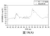
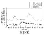
〔圖18(A)-18(B)〕為本發明體內去干擾試驗的結果,其中圖18(A)為無去干擾機制的量測曲線,圖18(B)為有去干擾機制的量測曲線。[Fig. 18(A)-18(B)] are the results of the in vivo de-interference test of the present invention, wherein Fig. 18(A) is the measurement curve without de-interference mechanism, and Fig. 18(B) is the amount with de-interference mechanism measurement curve.
以下在實施方式中詳細敘述本發明的詳細特徵以及優點,其內容足以使任何熟習相關技術者了解本發明的技術內容並據以實施,且根據本說明書所揭露的內容、申請專利範圍及圖式,任何熟習相關技術者可輕易地理解本發明相關的目的及優點。以下的實施例為進一步詳細說明本發明的觀點,但非以任何觀點限制本發明的範圍。The detailed features and advantages of the present invention are described in detail in the following embodiments, and the content is sufficient to enable any person skilled in the relevant art to understand the technical content of the present invention and implement it accordingly, and according to the content disclosed in this specification, the scope of the patent application and the drawings , any person skilled in the related art can easily understand the related objects and advantages of the present invention. The following examples are intended to illustrate the present invention in further detail, but are not intended to limit the scope of the present invention in any way.
本發明的微型生物感測器可為連續式葡萄糖監測系統的感測器,用於植入生物體皮下以持續量測生物流體中目標分析物的生理參數。另外,本文中所提到的「目標分析物」泛指任何存在於生物體內的待測物質,例如但不限於葡萄糖、乳糖(Lactose)、尿酸等。「生物流體」可為但不限於血液或人體組織間液(Interstitial Fluid,ISF),而「生理參數」可為但不限於濃度。The miniature biosensor of the present invention can be a sensor of a continuous glucose monitoring system, which is implanted subcutaneously in a living body to continuously measure the physiological parameters of a target analyte in a biological fluid. In addition, the "target analyte" mentioned herein generally refers to any substance to be tested that exists in the living body, such as but not limited to glucose, lactose (Lactose), uric acid and the like. The "biological fluid" may be, but not limited to, blood or human interstitial fluid (ISF), and the "physiological parameter" may be, but not limited to, concentration.
請參閱圖1(A),其為本發明微型生物感測器的第一實施例的正面示意圖。本發明的微型生物感測器10包括具有表面111的基板110、設置於基板110的表面111上的第一工作電極120及第二工作電極130、以及蓋覆於部分表面111、部分第一工作電極120及部分第二工作電極130上的絕緣層140。本發明的基板110為絕緣體。請參閱圖1(B),其移除絕緣層140可更清楚示意第一工作電極120及第二工作電極130在基板110的表面111上的配置,其中基板110包括表面111、對側表面112(請見圖2(A)、圖9(A)及圖9(B))、第一端113及第二端114,且基板110上靠近第一端113的區域為訊號輸出區域115、靠近第二端114的區段為感測區域116、以及位於訊號輸出區域115及感測區域116之間且被絕緣層140所覆蓋的區域為絕緣區域117。第一工作電極120及第二工作電極130從基板110的第一端113延伸至第二端114,第一工作電極120在感測區域116並包含第一導電材料1C的部分為第一感測段121,在訊號輸出區域115的部分為第一訊號輸出段122(如圖1(A)所示),而連接第一感測段121至第一訊號輸出段122並至少位於絕緣區域117的部分為第一訊號連接段123(如圖1(B)所示)。第二工作電極130在感測區域116並包含第二導電材料2C的部分為第二感測段131,在訊號輸出區域115的部分為第二訊號輸出段132(如圖1(A)所示),而連接第二感測段131至第二訊號輸出段132並至少位於絕緣區域117的部分為第二訊號連接段133(如圖1(B)所示)。本發明的第二感測段131鄰設於第一感測段121的至少一側邊並以其一側邊沿著第一感測段121的至少一側邊延伸。在第一實施例中,第二感測段131沿著第一感測段121的三側邊延伸而呈U形。因此,本發明的第一感測段121與第二感測段131僅藉表面111維持彼此間的關係位置,且第一感測段121與第二感測段131因直接相鄰而不存在如電極或連接線的中間物。Please refer to FIG. 1(A) , which is a schematic front view of the first embodiment of the miniature biosensor of the present invention. The
為了達成此等結構,在製程時,可先將第二導電材料2C形成於基板110的表面111上並圖案化成如圖1(B)的圖形,亦即將第二導電材料2C定義出兩個相互分離的區塊,其中從基板110的第一端113朝向第二端114延伸並在第二端114處彎折而呈U型的其中一區塊預設為第二工作電極130,而從基板110的第一端113朝向第二端114延伸並在第二端114處為前述U型結構所圍繞的另外一區塊預設為第一工作電極120。接著形成絕緣層140在基板110上並露出訊號輸出區域115與感測區域116後,可形成第一導電材料1C於第一工作電極120在感測區域116內的第二導電材料2C上,以完成第一工作電極120的第一感測段121。然而,雖未圖示,第一導電材料1C也可以僅形成於第一工作電極120在感測區域116內的部分第二導電材料2C上。因此,本發明圖1(A)中沿A-A’線、B-B’線及C-C’線的剖面示意圖分別為圖2(A)、2(B)及2(C)。在圖2(A)中,本發明第一實施例的第一感測段121具有覆蓋於第二導電材料2C上的第一導電材料1C,第二感測段131具有第二導電材料2C。在圖2(B)中是第二感測段131的U形底部區域,故在基板110的表面111上僅有第二導電材料2C。在圖2(C)中,由於第一導電材料1C僅形成於感測區域116內,故第一工作電極120位於絕緣區域117內的部分僅有第二導電材料2C且由絕緣層140覆蓋。In order to achieve these structures, during the manufacturing process, the second
在其他實施例中,蓋覆絕緣膠140的步驟也可在形成第一導電材料1C之後執行,故第一導電材料1C實質上可以形成於第一工作電極120中所有的第二導電材料2C上。此外,在本發明中可依需求改變第二導電材料2C在圖案化步驟後所保留的位置、大小與形狀,故在其他實施例中,第二導電材料2C可在圖案化步驟中被定義成如圖1(B)所示但沒有第一感測段121的圖形,也就是說第一工作電極120的第二導電材料2C僅形成於訊號輸出區域115與絕緣區域117內,或者頂多延伸至部分的感測區域116內,然後在原來表面111預計形成第一感測段121的區域直接形成第一導電材料1C於其上,並使第一導電材料1C電性連接至第一工作電極120的其他部分(即第二導電材料2C)以完成第一感測段121的配置,此時微型生物感測器10的感測區域116的剖面圖如圖2(D)所示。在其他實施例中,亦可在圖案化步驟時空出第一工作電極120的位置,再在蓋覆絕緣層140前以第一導電材料1C形成第一工作電極120。In other embodiments, the step of covering the insulating
在本發明的微型生物感測器10中,感測區域116中的第二感測段131與第一感測段121之間的間隙不大於0.2mm。更佳地,該間隙範圍為0.01mm至0.2mm;又更佳地,該間隙範圍為0.01mm至0.1mm;再更佳地,該間隙範圍為0.02mm至0.05mm。具體地,請參閱圖2(A),在第一實施例中第一感測段121與第二感測段131的間隙距離S3與S5為0.04mm。In the
另外,本發明的第一導電材料1C可為碳、鉑、鋁、鎵、金、銦、銥、鐵、鉛、鎂、鎳、鉬、鋨、鈀、銠、銀、錫、鈦、鋅、矽、鋯中的任一者、其衍生物(如合金、氧化物或金屬化合物等)或其組合,而第二導電材料2C同樣可使用如上述第一導電材料1C所例舉的元素或其衍生物。本發明的絕緣層140的材料可為任何能達到絕緣效果的材料,例如但不限於聚對二甲苯(Parylene)、聚醯亞胺(Polyimide)、聚二甲基矽氧烷(PDMS)、液晶高分子材料(LCP)或是MicroChem的SU-8光阻等。In addition, the first
請參閱圖3(A),其為本發明微型生物感測器10的第二實施例的正面示意圖,且圖3(B)中移除絕緣層140可更清楚地示意第一工作電極120及第二工作電極130在基板110的表面111上的配置。在第二實施例中,第一工作電極120及第二工作電極130從基板110的第一端113延伸至第二端114,第一工作電極120在感測區域116中且被第一導電材料1C所覆蓋的部分為第一感測段121,第二工作電極130在感測區域116並包含第二導電材料2C的部分為第二感測段131(如圖3(A)所示)。在第二實施例中,第二感測段131沿著第一感測段121的一側邊延伸而未彎折,使第二感測段131僅鄰設於第一感測段121的一側邊。因此,圖3(A)中沿A-A’線的剖面示意圖如圖4所示,本發明第二實施例的第一感測段121具有覆蓋於第二導電材料2C上的第一導電材料1C,以及第二感測段131具有第二導電材料2C且僅鄰設於第一感測段121的一側邊。Please refer to FIG. 3(A), which is a schematic front view of the second embodiment of the
請參閱圖5(A),其為本發明微型生物感測器10的第三實施例的正面示意圖。在第三實施例中,微型生物感測器10具有兩個第二工作電極130,第一工作電極120及兩個第二工作電極130從基板110的第一端113延伸至第二端114,且兩個第二工作電極130分別沿第一工作電極120的相對兩側邊延伸。第一工作電極120在感測區域116內且被第一導電材料1C所覆蓋的部分為第一感測段121,兩個第二工作電極130在感測區域116並包含第二導電材料2C的部分為第二感測段131。在第三實施例中,兩個第二感測段131分別鄰設於第一感測段121的相對兩側邊。因此,圖5(A)中沿A-A’線的剖面示意圖如圖5(B)所示,本發明第三實施例的第一感測段121具有覆蓋於第二導電材料2C上的第一導電材料1C,以及兩個第二感測段131具有第二導電材料2C且分別僅鄰設於第一感測段121的相對兩側邊。Please refer to FIG. 5(A) , which is a schematic front view of the third embodiment of the
儘管本發明的第一感測段121及第二感測段131間的配置已揭示如第一實施例至第三實施例所述,亦可有其他配置方式。舉例來說,在第一實施例中,第二感測段131為沿第一感測段121中彼此相鄰的三側邊延伸而呈U型,但在一變化例中,第二感測段131沿著第一感測段121的三側邊所延伸設置的長度也可進行調整而如圖6(A)所示,或者第二感測段131也可僅沿第一感測段121的相鄰兩側邊設置而呈成L型,如圖6(B)所示。在第一實施例的又一變化例中,第一工作電極120的第一訊號連接段123可透過在基板110上鑽孔洞118的方式穿設至基板110的對側表面112,此時第二感測段131可圍繞於第一感測段121的四側邊,如圖6(C)-6(D)所示。接著,不論是在第二實施例還是第三實施例中,第二感測段131的長度均可以相對於第一感測段121進行調整而如圖7至圖8(C)所示。因此,前述所謂「第二感測段131鄰設於第一感測段121的至少一側邊」具體指本發明的第一感測段121的周緣中鄰設有第二感測段131的部分佔第一感測段121的總周長的30%-100%。Although the configuration between the
再者,如圖1(A)、圖2(A)、圖3(A)、圖4、圖5(A)與圖5(B)所示,本發明的微型生物感測器10還包含一化學試劑層150。化學試劑層150至少覆蓋於第一感測段121的第一導電材料1C上。具體地,在微型生物感測器10的製程中可將表面111及/或對側表面112已經形成有電極的基板110浸入含有化學試劑的溶液中並調整基板110浸置的深度,使得後續形成的化學試劑層150可一次性地至少包覆微型生物感測器10的感測區域116,也就是同時覆蓋於第一感測段121的第一導電材料1C與覆蓋第二感測段131的第二導電材料2C上。又或者,化學試劑層150更可以包覆部份絕緣區域117,如圖1(A)所示。藉此,覆蓋於第一導電材料1C上的化學試劑層150可與生物流體中的目標分析物反應而產生生成物,後續由第一導電材料1C與生成物反應進而輸出對應於目標分析物的生理訊號。Furthermore, as shown in FIG. 1(A), FIG. 2(A), FIG. 3(A), FIG. 4, FIG. 5(A) and FIG. 5(B), the
在上述任一實施例中,本發明的雙工作電極的配置可應用於二電極系統和三電極系統。在二電極系統中,本發明的微型生物感測器10還包括配置在基板110的相對表面112上的至少一對電極160,如圖9(A)所示,圖9(A)是微型生物感測器10的感測區域116的剖面示意圖,而對電極160用以配合第一工作電極120或第二工作電極130作動。二電極系統中的對電極160可基於所選用的材質而兼具參考電極的功能,即本發明的對電極160可以與第一工作電極120形成電子迴路,使第一工作電極120上電流暢通,以確保電化學反應在第一工作電極120上發生之餘,還能提供穩定的相對電位作為參考電位。對電極160耦合到第一工作電極120和/或第二工作電極130。在其他實施例中,對電極160也可以被配置在基板110的表面111上(圖未示出)。在三電極系統中,本發明的微型生物感測器10除了對電極160外還包括一參考電極170,如圖9(B)所示,圖9(B)是微型生物感測器10的感測區域116的剖面示意圖,參考電極170用以提供參考電位。具體地,對電極160及參考電極170是分開且不電性連接的,而對電極160與第一工作電極120及/或第二工作電極130耦接。對電極160與參考電極170亦可設置於基板110的表面111上(圖未示出),或分別設置於基板110的不同表面上。此外,如圖所示,在本發明的一實施例中化學試劑層150實質上也覆蓋於對電極160及/或參考電極170上。In any of the above embodiments, the dual working electrode configuration of the present invention is applicable to both two-electrode systems and three-electrode systems. In the two-electrode system, the
必須說明的是,在本發明中所謂「驅動」為施加電壓讓其中一電極的電位高於另一電極的電位而使前述電位較高的電極開始進行氧化反應。因此,在第一工作電極120與對電極160之間造成第一工作電極120被驅動的電位差為第一工作電壓,且在第二工作電極130與對電極160之間造成第二工作電極130被驅動的電位差為第二工作電壓。It must be noted that, in the present invention, the term “driving” refers to applying a voltage to make the potential of one of the electrodes higher than the potential of the other electrode, so that the electrode with the higher potential starts the oxidation reaction. Therefore, the potential difference between the first working
進一步配合圖10來說明,本發明的微型生物感測器10的第一工作電極120被驅動而用於量測生物流體中目標分析物的生理參數,且當微型生物感測器10的第一工作電極120經第一工作電壓驅動時,第一感測段121會產生一量測範圍1S並對生成物具有第一靈敏度,使第一導電材料1C與生成物反應而產生電流訊號,電流訊號會經由第一訊號連接段123傳送至第一訊號輸出段122,且當電流訊號的數值與生成物的濃度間具有比例關係時,進而獲得對應生理參數的生理訊號。因此,當第一工作電極120以第一工作電壓驅動時,第一導電材料1C與生成物反應以輸出對應目標分析物的生理參數的生理訊號的動作為量測動作。然而,生物流體中含有干擾物,第一導電材料1C也會與干擾物反應而產生干擾電流訊號,干擾電流訊號會與電流訊號混合輸出而對生理訊號造成干擾。10 , the first working
本發明的微型生物感測器10的第二工作電極130可用以消耗干擾物。當微型生物感測器10的第二工作電極130經第二工作電壓驅動時,第二感測段131的第二導電材料2C對生成物具有一第二靈敏度,且每一第二感測段131均會產生一去干擾範圍2S。此時,因第二感測段131相當靠近第一感測段121而使得去干擾範圍2S接觸第一感測段121周遭並可至少部分重疊於第一感測段121的量測範圍1S,藉此第二導電材料2C會與干擾物進行氧化反應而直接且持續地消耗干擾物,降低干擾電流訊號的產生,進而降低干擾物對量測動作的影響。因此,當第二工作電極130以第二工作電壓驅動時,使第二導電材料2C消耗生物體中干擾物的動作為去干擾動作。The
再者,當第二工作電極130經第二工作電壓驅動時,第二導電材料2C亦有機會與生成物反應而產生另一電流訊號,但卻消耗掉原本應由第一工作電極120進行量測並藉以推知目標分析物的生理參數的生成物,進而影響實際被測得的生理參數。因此,當在一實施例中目標分析物為葡萄糖、生成物為過氧化氫、且生理參數為葡萄糖濃度時,第一導電材料1C更佳地需選用經第一工作電壓驅動後對於過氧化氫具有第一靈敏度的材料,且又更佳地,第一導電材料1C可選自於金、鉑、鈀、銥或前述的組合。而該第二導電材料2C需不同於該第一導電材料1C,且具體來說,需選用經第二工作電壓驅動後對於過氧化氫具有小於第一靈敏度的第二靈敏度的材料,甚至是經第二工作電壓驅動後對於過氧化氫幾乎不具靈敏度的材料(亦即第二靈敏度接近0或等於0)。更具體地,在本發明的一實施例中第一導電材料1C為鉑,而第一工作電壓範圍建議為0.2伏特(V)至0.8伏特(V),且較佳為0.4V至0.7V,第二導電材料2C為碳,而第二工作電壓範圍建議為0.2V至0.8V,且較佳為0.4V至0.7V。但在本發明的另一實施例中,第一導電材料1C為鉑,且第二導電材料2C為金。必須說明的是,上述鉑的形態可為鉑金屬、鉑黑(Platinum black)、鉑膏(Platinum paste)、其他含鉑材料或其組合。此外,第一工作電壓的數值可與第二工作電壓的數值相同,但本發明不以此為限。Furthermore, when the second working
接著,請參閱圖11與圖12進一步說明如何操作本發明的微型生物感測器10,其中圖11為控制本發明圖9(A)所示的微型生物感測器10的電壓並測量電流的電路的範例的示意圖,而圖12為本發明降低微型生物感測器10進行量測時所產生的干擾的方法流程圖。在圖11中,電流感測單元201會連接至微型生物感測器10的第一工作電極120,且另一電流感測單元202會連接至對電極160。電流感測單元201、202分別量測來自第一工作電極120及對電極160的電流訊號i1、i3。i2是第二工作電極130的電流訊號,亦可被其他電流感測單元量測(圖未示出)。在此範例中,第一工作電壓為第一工作電極120的電位V1與對電極160的電位V3間的差值,且第二工作電壓為第二工作電極130的電位V2與對電極160的電位V3間的差值。開關S1、S2可分別決定第一工作電極120及第二工作電極130是否通電壓。而本發明的降低量測干擾的方法如圖12所示包括提供微型生物感測器(步驟101),執行去干擾動作(步驟102),以及執行量測動作(步驟103)。本發明的去干擾動作與量測動作存在時間關係,其間可能的操作時序分別為:Next, please refer to FIG. 11 and FIG. 12 to further describe how to operate the
第一種時間關係:本發明的微型生物感測器會於期間T(如2週)內進行量測,且期間T包含多個第一子時間(T1)區段及/或多個第二子時間(T2)區段,在第一子時間(T1)區段時執行去干擾動作,在第二子時間(T2)區段時執行量測動作,且去干擾動作及量測動作皆為間隔進行。也就是說,執行方式依序為在第一個T1區段執行第一次去干擾動作以消耗干擾物、在第一個T2區段執行第一次量測動作以輸出對應當時生理參數的第一生理訊號、在第二個T1區段執行第二次去干擾動作以消耗干擾物、再於第二個T2區段執行第二次量測動作以輸出對應當時生理參數的第二生理訊號,依此類推,以得到生理參數在期間T中各個T2區段的所有表現。請參考圖13(A)至圖13(C),其中橫軸為時間,縱軸為電流,其中量測時序的線條表示第一工作電壓的施加和移除,而去干擾時序的線條表示第二工作電壓的施加和移除。在第一種時間關係中,T1區段與T2區段可以部份重疊(如圖13(A)所示)、不重疊(如圖13(B)所示)、或完全重疊(如圖13(C)所示)。在期間T中,任兩個T1區段間可利用移除該第二工作電壓的方式停止去干擾動作以作為區隔,且在任兩個T2區段間也可利用移除第一工作電壓的方式停止量測動作以作為兩個T2區段間的區隔。第一種時間關係中,T2區段的長度以能使電流訊號對應生成物的濃度並與生理參數間呈比例關係為條件,而T1區段的長度可以與T2區段的長度相同或比T2區段的長度長,以達到有效去除干擾為目標。The first time relationship: the micro biosensor of the present invention will perform measurement in a period T (eg, 2 weeks), and the period T includes a plurality of first sub-time (T1) segments and/or a plurality of second time periods In the sub-time (T2) segment, the interference-removing action is performed in the first sub-time (T1) segment, and the measurement action is performed in the second sub-time (T2) segment, and the interference-removing action and the measurement action are both: interval. That is to say, the execution method is to perform the first de-interference action in the first T1 section to consume the interference, and perform the first measurement action in the first T2 section to output the first time corresponding to the physiological parameter at that time. For a physiological signal, perform a second de-interference action in the second T1 section to consume the interference, and then perform a second measurement action in the second T2 section to output a second physiological signal corresponding to the current physiological parameter, And so on, to get all the manifestations of the physiological parameters in each T2 segment in the period T. Please refer to FIG. 13(A) to FIG. 13(C), in which the horizontal axis is time, and the vertical axis is current, wherein the line of measurement timing represents the application and removal of the first operating voltage, and the line of de-interference timing represents the first 2. Application and removal of operating voltage. In the first time relationship, the T1 segment and the T2 segment can partially overlap (as shown in Figure 13(A)), not overlap (as shown in Figure 13(B)), or completely overlap (as shown in Figure 13). (C) shown). During the period T, the interference removal operation can be stopped between any two T1 sections by removing the second working voltage as a section, and the first working voltage can also be removed between any two T2 sections. The method stops the measurement action as the interval between the two T2 sections. In the first time relationship, the length of the T2 segment is such that the current signal corresponds to the concentration of the product and is proportional to the physiological parameterThe relationship is a condition, and the length of the T1 segment can be the same as the length of the T2 segment or longer than the length of the T2 segment, in order to achieve the goal of effectively removing interference.
此外,如圖13(A)或圖13(B)所示,第一次去干擾動作較佳地可比第一次量測動作早執行或同時執行,以有效地避免體內該干擾物對於該量測的干擾。也就是說,當有複數次量測動作時,去干擾動作至少執行一次且其較佳地啟動在不晚於各複數次量測動作的第一次量測動作開始時。In addition, as shown in FIG. 13(A) or FIG. 13(B) , the first de-interference action can preferably be performed earlier than or simultaneously with the first measurement action, so as to effectively avoid the interference of the interfering substance in the body with the amount of measured interference. That is to say, when there are a plurality of measurement actions, the interference removal action is performed at least once and is preferably started no later than the start of the first measurement action of each of the plurality of measurement actions.
第二種時間關係:本發明的微型生物感測器會於期間T(如2週)內進行量測,且期間T包含多個子時間區段,在整個期間T執行去干擾動作,並在各個子時間區段執行量測動作,且量測動作為間隔進行。也就是說,請參閱圖14,第二種時間關係為在整個期間T內不間斷地執行去干擾動作以消耗干擾物直到期間結束,於此同時在第一個子時間區段執行第一次量測動作以輸出對應當時生理參數的第一生理訊號,且執行第一次量測動作後隔一段時間再於在第二個子時間區段執行第二次量測動作以輸出對應當時生理參數的第二生理訊號,依此類推,以得到生理參數在期間T中各個子時間區段的所有表現。在期間T中,任兩個子時間區段間可利用移除第一工作電壓的方式停止量測動作,以作為間隔。第二種時間關係中,各個子時間區段的長度可以相同或不相同,且其長度同樣地以使電流訊號能對應生成物的濃度並與生理參數間呈比例關係為條件。The second time relationship: the micro biosensor of the present invention will perform measurement in a period T (such as 2 weeks), and the period T includes a plurality of sub-periods, and the interference removal action is performed during the entire period T, and each The sub-time segment performs the measurement action, and the measurement action is performed at intervals. That is to say, referring to FIG. 14 , the second time relationship is that the de-interference action is continuously performed in the whole period T to consume the distractor until the end of the period, and at the same time, the first time is performed in the first sub-time segment. The measurement action is to output the first physiological signal corresponding to the physiological parameter at that time, and after the first measurement action is performed, a second measurement action is performed in the second sub-time section after a period of time to output the signal corresponding to the physiological parameter at that time. The second physiological signal, and so on, to obtain all the manifestations of the physiological parameters in each sub-time segment in the period T. In the period T, the measurement operation can be stopped by removing the first working voltage as an interval between any two sub-time sections. In the second time relationship, the lengths of each sub-time segment can be the same or different, and the lengths are also conditional on the condition that the current signal can correspond to the concentration of the product and has a proportional relationship with the physiological parameter.
第三種時間關係:雖未圖示,但第三種時間關係與第二種時間關係不同的是,第三種時間關係為在整個期間T不間斷地執行量測動作,在各個子時間區段時執行去干擾動作,也就是說去干擾動作為間隔進行。The third time relationship: Although not shown in the figure, the third time relationship is different from the second time relationship in that the third time relationship is that the measurement movement is performed continuously throughout the period T.If the operation is performed, the de-interference action is performed in each sub-time segment, that is to say, the de-interference action is performed at intervals.
第四種時間關係:請參考圖15,本發明的微型生物感測器會於期間T(如2週)內進行量測,且在整個期間T內不間斷地執行量測動作,且同時也不間斷地執行去干擾動作直至期間結束,以連續去除干擾物及量測生理參數。The fourth time relationship: please refer to FIG. 15 , the micro biosensor of the present invention will perform measurement in a period T (eg, 2 weeks), and continuously perform the measurement during the entire period T, and at the same time also The interference removal action is performed continuously until the end of the period to continuously remove the interference and measure the physiological parameters.
體外(In vitro)去干擾試驗In vitro deinterference test
[試驗例][Test example]
在試驗例中使用具有第一實施例的雙工作電極結構的微型生物感測器進行量測,其中第一感測段為覆蓋有鉑黑的碳電極、第二感測段為碳電極、第一工作電壓為0.5V、以及第二工作電壓為0.5V、且干擾物為乙醯胺酚。In the test example, the micro biosensor with the dual working electrode structure of the first embodiment is used for measurement, wherein the first sensing segment is a carbon electrode covered with platinum black, the second sensing segment is a carbon electrode, and the second sensing segment is a carbon electrode. The first working voltage is 0.5V, the second working voltage is 0.5V, and the interfering substance is acetaminophen.
[比較試驗例][Comparative test example]
在比較試驗例中所使用的微型生物感測器與試驗例相同,但不施加第二工作電壓。由於不施加第二工作電壓,第二感測段131不會被驅動,故僅有第一感測段121的量測範圍1S,如圖16所示。The micro biosensor used in the comparative test example is the same as the test example, but the second working voltage is not applied. Since the second operating voltage is not applied, the
接著,利用本發明的微型生物感測器進行體外去干擾試驗的方式如下。首先,將試驗例與比較試驗例的微型生物感測器分別於不同時間區間(P1至P9)依序浸入分別含有磷酸鹽緩衝生理鹽水(PBS)溶液、40mg/dL葡萄糖溶液、100mg/dL葡萄糖溶液、300mg/dL葡萄糖溶液、500mg/dL葡萄糖溶液、100mg/dL葡萄糖溶液、摻入2.5mg/dL乙醯胺酚的100mg/dL葡萄糖溶液、100mg/dL葡萄糖溶液及摻入5mg/dL乙醯胺酚的100mg/dL葡萄糖溶液,試驗結果如圖17所示,其中在試驗例中於第一感測段121所測得的電流訊號為曲線C1,於第二感測段131所測得的電流訊號為曲線C2,而在比較試驗例中於第一感測段121所測得的電流訊號為曲線C3。Next, the method of using the micro biosensor of the present invention to perform the in vitro de-interference test is as follows. First, the micro biosensors of the test example and the comparative test example were immersed in a phosphate-buffered saline (PBS) solution, a 40 mg/dL glucose solution, and a 100 mg/dL glucose solution in sequence at different time intervals (P1 to P9). solution, 300 mg/dL dextrose solution, 500 mg/dL dextrose solution, 100 mg/dL dextrose solution, 100 mg/dL dextrose solution spiked with 2.5 mg/dL acetaminophen, 100 mg/dL dextrose solution and 5100 mg/dL glucose solution of mg/dL acetaminophen, the test results are shown in FIG. 17 , wherein in the test example, the current signal measured in the
從圖16的時間區間P1至P5中可以看出,不論是試驗例還是比較試驗例的第一感測段在不同時間區段都會隨著不同濃度的葡萄糖產生不同強度的電流訊號,也就是說第一感測段的電流訊號與生理參數之間具有比例關係,但試驗例的第二感測段則沒有電流訊號產生,表示第二感測段對葡萄糖經由酵素催化後所衍生的副產物過氧化氫的反應性非常低,接近0或等於0。接著,從曲線C3可以看出,當將比較試驗例的微型生物感測器於時間區段P7浸入含有2.5mg/dL乙醯胺酚的100mg/dL葡萄糖溶液時,相較其於時間區段P3的電流訊號,第一感測段121在時間區段P7所測得的電流訊號顯然受到乙醯胺酚的干擾而飄高,且量測受干擾的程度在將微型生物感測器於時間區段P9浸入含有5mg/dL乙醯胺酚的100mg/dL葡萄糖溶液時更為明顯。反之,從曲線C1與曲線C2可以看出,當將試驗例的微型生物感測器於時間區段P7浸入含有2.5mg/dL乙醯胺酚的100mg/dL葡萄糖溶液時,其電流訊號與時間區段P3的電流表現一致,也就是說當以第二工作電壓驅動第二工作電極130進行去干擾動作時,可降低第一感測段121受到乙醯胺酚影響的程度,即使提高乙醯胺酚的濃度亦然。從另一方面來看,因第二工作電極130的第二感測段131用以消耗乙醯胺酚,故其在PBS溶液及葡萄糖溶液皆沒有電流訊號,但當有乙醯胺酚時便會產生電流訊號。由此可知,當量測環境(即前述量測範圍)中有乙醯胺酚,第二感測段131會消耗乙醯胺酚,降低第一感測段121的量測受乙醯胺酚干擾的可能。藉此,本發明的微型生物感測器可以量測出更準確的生理參數。It can be seen from the time intervals P1 to P5 in FIG. 16 that the first sensing section of the test example and the comparative test example will generate current signals of different intensities with different concentrations of glucose in different time sections, that is to say There is a proportional relationship between the current signal of the first sensing segment and the physiological parameters, but no current signal is generated in the second sensing segment of the test case, which means that the second sensing segment is responsible for the passage of by-products derived from glucose catalyzed by enzymes. The reactivity of hydrogen oxide is very low, close to or equal to zero. Next, as can be seen from the curve C3, when the micro biosensor of the comparative test example was immersed in a 100 mg/dL glucose solution containing 2.5 mg/dL acetaminophen in the time period P7, compared with the current in the time period P3 Signal, the current signal measured by the
體內(In vivo)去干擾試驗In vivo deinterference test
在體內去干擾試驗中同樣使用具有本發明第一實施例的雙工作電極架構的微型生物感測器進行量測,其中第一感測段為覆蓋有鉑黑的碳電極、第二感測段為碳電極、第一工作電壓為0.5V、第二工作電壓為0.5V。將微型生物感測器實際用於植入人體皮下以持續監測組織間液中的葡萄糖濃度,並於第86小時的時候服用1g普拿疼(其主要成分為乙醯胺酚),量測有去干擾機制與無去干擾機制的數據,並與傳統血糖儀(Blood Glucose Meter,BGM)比較,其實驗結果如圖18(A)-18(B)所示,其中圖18(A)為無去干擾機制的量測曲線,圖18(B)為有去干擾機制的量測曲線。In the in vivo anti-interference test, the micro biosensor with the dual working electrode structure of the first embodiment of the present invention is also used for measurement, wherein the first sensing segment is a carbon electrode covered with platinum black, and the second sensing segment is It is a carbon electrode, the first working voltage is 0.5V, and the second working voltage is 0.5V. The miniature biosensor was actually implanted into the human body to continuously monitor the glucose concentration in the interstitial fluid, and 1g of Panadol (the main component of which was acetaminophen) was taken at the 86th hour. The measurement has a de-interference mechanism. Compared with the data without interference mechanism and compared with the traditional blood glucose meter (Blood Glucose Meter, BGM), the experimental results are shown in Figure 18(A)-18(B), wherein Figure 18(A) is without interference mechanism The measurement curve of , Figure 18(B) is the measurement curve with the interference removal mechanism.
在圖18(A)-18(B)中,黑點為傳統血糖儀所測得的數值,虛線為本發明微型生物感測器中第一工作電極的量測曲線,且實線為本發明微型生物感測器中第二工作電極的量測曲線。從圖18(A)圖中可以看出當沒有開啟去干擾功能時,在第90-96小時左右本發明微型生物感測器的第一工作電極所量測的數值均有飄高的現象(即服用1g普拿疼後4-6小時反應時間)。相反的,圖18(B)圖中可以看出若開啟去干擾功能,本發明微型生物感測器的第二工作電極會測得相對應的電流值,且第一工作電極的量測數值無飄高的現象並可與傳統血糖儀的數值相匹配。18(A)-18(B), the black dots are the values measured by the conventional blood glucose meter, the dotted lines are the measurement curves of the first working electrode in the micro biosensor of the present invention, and the solid lines are the present invention Measurement curve of the second working electrode in the miniature biosensor. It can be seen from Fig. 18(A) that when the anti-interference function is not turned on, the values measured by the first working electrode of the micro biosensor of the present invention all float up around the 90th to 96th hour ( That is, the reaction time is 4-6 hours after taking 1g of Punapain). On the contrary, it can be seen from FIG. 18(B) that if the anti-interference function is turned on, the second working electrode of the micro biosensor of the present invention will measure the corresponding current value, and the measured value of the first working electrode has no value. The phenomenon of floating high can be compared with the value of traditional blood glucose meter.match.
另外,當微型生物感測器有開啟去干擾功能時,其於無藥物干擾期間的平均誤差值為0.1mg/dL,於藥物干擾期間的平均誤差值為-2.1mg/dL,總誤差值為-1.1mg/dL,而於藥物干擾期間的平均絕對相對偏差值(Mean Absolute Relative Difference,MARD)為4.6。當微型生物感測器沒有開啟去干擾功能時,其於無藥物干擾期間的平均誤差值為-0.2mg/dL,但於藥物干擾期間的平均誤差值為12.6mg/dL,總誤差值為6.7mg/dL,而於藥物干擾期間的平均絕對相對偏差值為10.6。由此可知,藉由第二工作電極130的第二感測段131消耗干擾物的動作確實可以降低干擾物對第一感測段121量測生理訊號的影響至小於或等於一誤差範圍,如20%,且更具體地為10%。綜上所述,本發明將微型生物感測器中的第二感測段鄰設於第一感測段的至少一側邊,使第二感測段得以直接且連續地消耗第一感測段周遭的的干擾物,進而降低干擾物對第一感測段的量測干擾,使微型生物感測器可以量測出更準確的數據。In addition, when the micro biosensor has the anti-interference function turned on, the average error value during the period without drug interference is 0.1mg/dL, and the average error value during the drug interference period is -2.1mg/dL, and the total error value is -1.1 mg/dL and the Mean Absolute Relative Difference (MARD) during drug interference was 4.6. When the micro biosensor does not have the anti-interference function turned on, the average error value during the period without drug interference is -0.2mg/dL, but the average error value during the drug interference period is 12.6mg/dL, and the total error value is 6.7 mg/dL, while the mean absolute relative deviation value during the drug interference period was 10.6. It can be seen from this that the action of consuming the interferer by the
本發明實屬難能的創新發明,深具產業價值,援依法提出申請。此外,本發明可以由所屬技術領域中具有通常知識者做任何修改,但不脫離如所附申請專利範圍所要保護的範圍。The present invention is a difficult innovative invention with profound industrial value, and an application is filed in accordance with the law. Furthermore, the present invention can be modified in any way by those of ordinary skill in the art without departing from the scope of protection as intended by the appended claims.
Claims (23)
Translated fromChineseApplications Claiming Priority (4)
| Application Number | Priority Date | Filing Date | Title |
|---|---|---|---|
| US201962882162P | 2019-08-02 | 2019-08-02 | |
| US62/882,162 | 2019-08-02 | ||
| US202062988549P | 2020-03-12 | 2020-03-12 | |
| US62/988,549 | 2020-03-12 |
Publications (2)
| Publication Number | Publication Date |
|---|---|
| TW202109040A TW202109040A (en) | 2021-03-01 |
| TWI770571Btrue TWI770571B (en) | 2022-07-11 |
Family
ID=71943924
Family Applications (11)
| Application Number | Title | Priority Date | Filing Date |
|---|---|---|---|
| TW109125962ATWI755802B (en) | 2019-08-02 | 2020-07-31 | Implantable Micro Biosensor |
| TW109125968ATWI799725B (en) | 2019-08-02 | 2020-07-31 | Implantable miniature biosensor and method of operation thereof |
| TW109125964ATWI755803B (en) | 2019-08-02 | 2020-07-31 | Implantable miniature biosensor and its manufacturing method |
| TW109126240ATWI736383B (en) | 2019-08-02 | 2020-08-03 | Mirco biosensor and measuring method thereof |
| TW109126239ATWI783250B (en) | 2019-08-02 | 2020-08-03 | Mirco biosensor and measuring method thereof |
| TW111132568ATWI788274B (en) | 2019-08-02 | 2020-08-03 | Mirco biosensor and measuring method thereof |
| TW109126241ATWI805938B (en) | 2019-08-02 | 2020-08-03 | Biosensor and method for determining dimension of counter electrode and prolonging usage lifetime of the same |
| TW109126238ATWI783249B (en) | 2019-08-02 | 2020-08-03 | Mirco biosensor and measuring method thereof |
| TW109126201ATWI757811B (en) | 2019-08-02 | 2020-08-03 | Micro biosensor and method for reducing measurement interference using the same |
| TW109126213ATWI770571B (en) | 2019-08-02 | 2020-08-03 | Method for reducing measurement interference of micro biosensor |
| TW111132569ATWI784921B (en) | 2019-08-02 | 2020-08-03 | Mirco biosensor and measuring method thereof |
Family Applications Before (9)
| Application Number | Title | Priority Date | Filing Date |
|---|---|---|---|
| TW109125962ATWI755802B (en) | 2019-08-02 | 2020-07-31 | Implantable Micro Biosensor |
| TW109125968ATWI799725B (en) | 2019-08-02 | 2020-07-31 | Implantable miniature biosensor and method of operation thereof |
| TW109125964ATWI755803B (en) | 2019-08-02 | 2020-07-31 | Implantable miniature biosensor and its manufacturing method |
| TW109126240ATWI736383B (en) | 2019-08-02 | 2020-08-03 | Mirco biosensor and measuring method thereof |
| TW109126239ATWI783250B (en) | 2019-08-02 | 2020-08-03 | Mirco biosensor and measuring method thereof |
| TW111132568ATWI788274B (en) | 2019-08-02 | 2020-08-03 | Mirco biosensor and measuring method thereof |
| TW109126241ATWI805938B (en) | 2019-08-02 | 2020-08-03 | Biosensor and method for determining dimension of counter electrode and prolonging usage lifetime of the same |
| TW109126238ATWI783249B (en) | 2019-08-02 | 2020-08-03 | Mirco biosensor and measuring method thereof |
| TW109126201ATWI757811B (en) | 2019-08-02 | 2020-08-03 | Micro biosensor and method for reducing measurement interference using the same |
Family Applications After (1)
| Application Number | Title | Priority Date | Filing Date |
|---|---|---|---|
| TW111132569ATWI784921B (en) | 2019-08-02 | 2020-08-03 | Mirco biosensor and measuring method thereof |
Country Status (9)
| Country | Link |
|---|---|
| US (11) | US12023150B2 (en) |
| EP (10) | EP3771410A1 (en) |
| JP (6) | JP7143373B2 (en) |
| KR (5) | KR102506277B1 (en) |
| CN (11) | CN112294320B (en) |
| AU (5) | AU2020210303B2 (en) |
| CA (5) | CA3104900A1 (en) |
| TW (11) | TWI755802B (en) |
| WO (4) | WO2021024132A1 (en) |
Families Citing this family (15)
| Publication number | Priority date | Publication date | Assignee | Title |
|---|---|---|---|---|
| KR102506277B1 (en)* | 2019-08-02 | 2023-03-07 | 바이오나임 코포레이션 | Micro biosensor and measuring method thereof |
| TWI770871B (en)* | 2020-03-12 | 2022-07-11 | 華廣生技股份有限公司 | Method for recovering biological sensor and device using same |
| EP3928697A1 (en) | 2020-06-23 | 2021-12-29 | Roche Diabetes Care GmbH | Analyte sensor and a method for producing an analyte sensor |
| US20240182998A1 (en) | 2021-03-08 | 2024-06-06 | Kabushiki Kaisha Kobe Seiko Sho (Kobe Steel, Ltd.) | Method for manufacturing steel sheet |
| CO2021005504A1 (en)* | 2021-04-27 | 2022-10-31 | Pontificia Univ Javeriana | Device for electronic and electrochemical measurement of analyte concentrations in biological samples |
| JP2024526365A (en)* | 2021-07-22 | 2024-07-17 | 華廣生技股▲ふん▼有限公司 | Microbiosensors and their sensing structures |
| US20230112140A1 (en)* | 2021-10-07 | 2023-04-13 | Uxn Co., Ltd. | Electrochemical sensor, continuous analyte meter including electrochemical sensor, and method of fabricating electrochemical sensor |
| KR102813850B1 (en)* | 2021-10-07 | 2025-05-28 | 주식회사 유엑스엔 | Electrochemical biosensor |
| CN114748208B (en)* | 2022-04-15 | 2024-01-12 | 柔脉医疗(深圳)有限公司 | Tissue engineering scaffold capable of in-situ detecting multiple chemical and biological components |
| JP2025524533A (en)* | 2022-07-05 | 2025-07-30 | バイオリンク インコーポレイテッド | Sensor assembly for a microneedle array-based continuous analyte monitoring device |
| CN119604234A (en)* | 2022-07-26 | 2025-03-11 | 豪夫迈·罗氏有限公司 | Method and analyte sensor system for detecting at least one analyte |
| CN115541670B (en)* | 2022-10-09 | 2025-03-14 | 深圳市优维健康科技有限公司 | Preparation method of dynamic blood glucose meter sensor and implantable sensor |
| WO2024144266A2 (en)* | 2022-12-29 | 2024-07-04 | 주식회사 아이센스 | Complex sensor capable of measuring two or more analytes |
| CN116421191B (en)* | 2023-03-08 | 2024-08-06 | 宁波康麦隆医疗器械有限公司 | Flexible integrated bioelectric signal sensor, detection method and device |
| CN116626132A (en)* | 2023-05-15 | 2023-08-22 | 广州达安基因股份有限公司 | Implantable biosensor and preparation method thereof |
Citations (3)
| Publication number | Priority date | Publication date | Assignee | Title |
|---|---|---|---|---|
| CN102438517A (en)* | 2009-02-26 | 2012-05-02 | 雅培糖尿病护理公司 | Improved analyte sensors and methods of making and using the same |
| CN107122703A (en)* | 2017-03-15 | 2017-09-01 | 深圳信炜科技有限公司 | Biological information sensing device, electronic equipment and common mode disturbances detection method |
| TW201833549A (en)* | 2017-01-31 | 2018-09-16 | 瑞士商希拉格國際有限公司 | Determining an analyte concentration of a physiological fluid having an interferent |
Family Cites Families (163)
| Publication number | Priority date | Publication date | Assignee | Title |
|---|---|---|---|---|
| US3719576A (en)* | 1971-01-29 | 1973-03-06 | Gen Electric | Electrode for measuring co2 tension in blood and other liquid and gaseous environments |
| US3957612A (en)* | 1974-07-24 | 1976-05-18 | General Electric Company | In vivo specific ion sensor |
| GB2012435B (en)* | 1978-01-11 | 1982-10-27 | Environmental Sciences Ass | Electrochemical testing system |
| JPS57118152A (en)* | 1981-01-14 | 1982-07-22 | Matsushita Electric Ind Co Ltd | Enzyme electrode |
| JPS6423155A (en)* | 1987-07-17 | 1989-01-25 | Daikin Ind Ltd | Electrode refreshing device for biosensor |
| US5200051A (en)* | 1988-11-14 | 1993-04-06 | I-Stat Corporation | Wholly microfabricated biosensors and process for the manufacture and use thereof |
| US5078854A (en)* | 1990-01-22 | 1992-01-07 | Mallinckrodt Sensor Systems, Inc. | Polarographic chemical sensor with external reference electrode |
| AU7226994A (en)* | 1993-07-28 | 1995-02-28 | Novo Nordisk A/S | Reference electrode |
| AUPN363995A0 (en)* | 1995-06-19 | 1995-07-13 | Memtec Limited | Electrochemical cell |
| US6002954A (en)* | 1995-11-22 | 1999-12-14 | The Regents Of The University Of California | Detection of biological molecules using boronate-based chemical amplification and optical sensors |
| JP3800252B2 (en)* | 1996-01-10 | 2006-07-26 | 王子製紙株式会社 | Concentration measuring method and apparatus |
| DE19605739C1 (en) | 1996-02-16 | 1997-09-04 | Wolfgang Dr Fleckenstein | Brain pO2 measuring device |
| US20050033132A1 (en)* | 1997-03-04 | 2005-02-10 | Shults Mark C. | Analyte measuring device |
| JP2002505008A (en)* | 1997-06-16 | 2002-02-12 | エラン コーポレーション ピーエルシー | Methods for calibrating and testing sensors for in vivo measurement of analytes and devices for use in such methods |
| US6134461A (en)* | 1998-03-04 | 2000-10-17 | E. Heller & Company | Electrochemical analyte |
| CA2265119C (en)* | 1998-03-13 | 2002-12-03 | Cygnus, Inc. | Biosensor, iontophoretic sampling system, and methods of use thereof |
| US8688188B2 (en) | 1998-04-30 | 2014-04-01 | Abbott Diabetes Care Inc. | Analyte monitoring device and methods of use |
| US6175752B1 (en)* | 1998-04-30 | 2001-01-16 | Therasense, Inc. | Analyte monitoring device and methods of use |
| US8974386B2 (en)* | 1998-04-30 | 2015-03-10 | Abbott Diabetes Care Inc. | Analyte monitoring device and methods of use |
| US6338790B1 (en)* | 1998-10-08 | 2002-01-15 | Therasense, Inc. | Small volume in vitro analyte sensor with diffusible or non-leachable redox mediator |
| EP1192269A2 (en)* | 1999-06-18 | 2002-04-03 | Therasense, Inc. | MASS TRANSPORT LIMITED i IN VIVO /i ANALYTE SENSOR |
| US6682649B1 (en)* | 1999-10-01 | 2004-01-27 | Sophion Bioscience A/S | Substrate and a method for determining and/or monitoring electrophysiological properties of ion channels |
| WO2001088534A2 (en)* | 2000-05-16 | 2001-11-22 | Cygnus, Inc. | Methods for improving performance and reliability of biosensors |
| US6872297B2 (en) | 2001-05-31 | 2005-03-29 | Instrumentation Laboratory Company | Analytical instruments, biosensors and methods thereof |
| TWI244550B (en)* | 2001-06-21 | 2005-12-01 | Hmd Biomedical Inc | Electrochemistry test unit, biological sensor, the manufacturing method, and the detector |
| US20030032874A1 (en)* | 2001-07-27 | 2003-02-13 | Dexcom, Inc. | Sensor head for use with implantable devices |
| US6964871B2 (en)* | 2002-04-25 | 2005-11-15 | Home Diagnostics, Inc. | Systems and methods for blood glucose sensing |
| US7736309B2 (en)* | 2002-09-27 | 2010-06-15 | Medtronic Minimed, Inc. | Implantable sensor method and system |
| EP1557662B1 (en)* | 2002-10-31 | 2016-07-13 | Panasonic Healthcare Holdings Co., Ltd. | Determination method for automatically identifying analyte liquid and standard solution for biosensor |
| JP4535741B2 (en)* | 2003-01-30 | 2010-09-01 | 株式会社タニタ | Measuring method using chemical sensor and chemical sensor type measuring device |
| US7132041B2 (en)* | 2003-02-11 | 2006-11-07 | Bayer Healthcare Llc | Methods of determining the concentration of an analyte in a fluid test sample |
| US9763609B2 (en)* | 2003-07-25 | 2017-09-19 | Dexcom, Inc. | Analyte sensors having a signal-to-noise ratio substantially unaffected by non-constant noise |
| US7074307B2 (en) | 2003-07-25 | 2006-07-11 | Dexcom, Inc. | Electrode systems for electrochemical sensors |
| ES2709991T3 (en)* | 2003-08-21 | 2019-04-22 | Agamatrix Inc | Method and apparatus for the analysis of electrochemical properties |
| US20050067277A1 (en)* | 2003-09-30 | 2005-03-31 | Pierce Robin D. | Low volume electrochemical biosensor |
| WO2005040404A1 (en)* | 2003-10-29 | 2005-05-06 | Agency For Science, Technology And Research | Biosensor |
| DE602004021835D1 (en) | 2003-10-31 | 2009-08-13 | Lifescan Scotland Ltd | METHOD FOR REDUCING INTERFERENCE IN AN ELECTROCHEMICAL SENSOR USING TWO DIFFERENT APPROPRIATE POTENTIALS |
| ATE480761T1 (en)* | 2003-12-05 | 2010-09-15 | Dexcom Inc | CALIBRATION METHODS FOR A CONTINUOUSLY WORKING ANALYTICAL SENSOR |
| US8423114B2 (en) | 2006-10-04 | 2013-04-16 | Dexcom, Inc. | Dual electrode system for a continuous analyte sensor |
| US11633133B2 (en)* | 2003-12-05 | 2023-04-25 | Dexcom, Inc. | Dual electrode system for a continuous analyte sensor |
| US7125382B2 (en)* | 2004-05-20 | 2006-10-24 | Digital Angel Corporation | Embedded bio-sensor system |
| JP2008510506A (en)* | 2004-08-20 | 2008-04-10 | ノボ・ノルデイスク・エー/エス | Manufacturing process for forming narrow sensors |
| KR100698961B1 (en)* | 2005-02-04 | 2007-03-26 | 주식회사 아이센스 | Electrochemical Biosensor |
| DE602005002344T2 (en)* | 2005-03-03 | 2008-06-12 | Apex Biotechnology Corporation | Method for reducing the measurement deviation of amperometric biosensors |
| US7695600B2 (en)* | 2005-06-03 | 2010-04-13 | Hypoguard Limited | Test system |
| JP5385607B2 (en) | 2005-07-20 | 2014-01-08 | バイエル・ヘルスケア・エルエルシー | Gated current measuring instrument |
| US7846311B2 (en) | 2005-09-27 | 2010-12-07 | Abbott Diabetes Care Inc. | In vitro analyte sensor and methods of use |
| DE502006004037D1 (en) | 2005-12-19 | 2009-07-30 | Roche Diagnostics Gmbh | SANDWICH SENSOR TO DETERMINE AN ANALYTIC CONCENTRATION |
| JP4394654B2 (en)* | 2006-02-24 | 2010-01-06 | 三菱重工環境・化学エンジニアリング株式会社 | Pyrolysis gas treatment method and apparatus for high water content organic carbonization system |
| US7887682B2 (en)* | 2006-03-29 | 2011-02-15 | Abbott Diabetes Care Inc. | Analyte sensors and methods of use |
| US8346335B2 (en)* | 2008-03-28 | 2013-01-01 | Abbott Diabetes Care Inc. | Analyte sensor calibration management |
| ATE514942T1 (en)* | 2006-04-10 | 2011-07-15 | Bayer Healthcare Llc | CORRECTION OF OXYGEN EFFECTS IN A TEST SENSOR USING REAGENTS |
| GB0607205D0 (en) | 2006-04-10 | 2006-05-17 | Diagnoswiss Sa | Miniaturised biosensor with optimized anperimetric detection |
| BRPI0711433A2 (en)* | 2006-05-08 | 2011-11-16 | Bayer Healthcare Llc | Abnormal output detection system for a biosensor |
| US20070299617A1 (en)* | 2006-06-27 | 2007-12-27 | Willis John P | Biofouling self-compensating biosensor |
| AU2006348994A1 (en)* | 2006-10-04 | 2008-04-10 | Dexcom, Inc. | Dual electrode system for a continuous analyte sensor |
| ES2825036T3 (en)* | 2006-10-24 | 2021-05-14 | Ascensia Diabetes Care Holdings Ag | Transient decay amperometry |
| US20080214912A1 (en)* | 2007-01-10 | 2008-09-04 | Glucose Sensing Technologies, Llc | Blood Glucose Monitoring System And Method |
| US8808515B2 (en)* | 2007-01-31 | 2014-08-19 | Abbott Diabetes Care Inc. | Heterocyclic nitrogen containing polymers coated analyte monitoring device and methods of use |
| US20200037874A1 (en)* | 2007-05-18 | 2020-02-06 | Dexcom, Inc. | Analyte sensors having a signal-to-noise ratio substantially unaffected by non-constant noise |
| EP2179027A4 (en)* | 2007-07-23 | 2013-12-04 | Agamatrix Inc | Electrochemical test strip |
| CN101520428B (en) | 2008-02-25 | 2013-05-01 | 华广生技股份有限公司 | Electrochemical sensing method and test piece |
| WO2009121026A1 (en)* | 2008-03-28 | 2009-10-01 | Dexcom, Inc. | Polymer membranes for continuous analyte sensors |
| US8583204B2 (en)* | 2008-03-28 | 2013-11-12 | Dexcom, Inc. | Polymer membranes for continuous analyte sensors |
| US8280474B2 (en)* | 2008-06-02 | 2012-10-02 | Abbott Diabetes Care Inc. | Reference electrodes having an extended lifetime for use in long term amperometric sensors |
| US8155722B2 (en) | 2008-06-02 | 2012-04-10 | Abbott Diabetes Care Inc. | Reference electrodes having an extended lifetime for use in long term amperometric sensors |
| US8620398B2 (en) | 2008-06-02 | 2013-12-31 | Abbott Diabetes Care Inc. | Reference electrodes having an extended lifetime for use in long term amperometric sensors |
| US8700114B2 (en)* | 2008-07-31 | 2014-04-15 | Medtronic Minmed, Inc. | Analyte sensor apparatuses comprising multiple implantable sensor elements and methods for making and using them |
| US20100025238A1 (en)* | 2008-07-31 | 2010-02-04 | Medtronic Minimed, Inc. | Analyte sensor apparatuses having improved electrode configurations and methods for making and using them |
| JP5228891B2 (en) | 2008-11-21 | 2013-07-03 | 株式会社リコー | Sensor device |
| US20100169035A1 (en)* | 2008-12-29 | 2010-07-01 | Medtronic Minimed, Inc. | Methods and systems for observing sensor parameters |
| US20100204556A1 (en)* | 2009-02-12 | 2010-08-12 | Keimar, Inc. | Physiological parameter sensors |
| EP2416893B1 (en)* | 2009-02-24 | 2013-10-30 | Ultradian Diagnostics LLC | Microsecond response electrochemical sensors and methods thereof |
| CN104825171B (en)* | 2009-02-26 | 2017-08-04 | 雅培糖尿病护理公司 | Improved analyte sensor and production and preparation method thereof |
| US20100219085A1 (en)* | 2009-02-27 | 2010-09-02 | Edwards Lifesciences Corporation | Analyte Sensor Offset Normalization |
| GR1007310B (en)* | 2009-03-09 | 2011-06-10 | Αχιλλεας Τσουκαλης | Implantable biosensor with automatic calibration |
| US8359081B2 (en) | 2009-04-28 | 2013-01-22 | Abbott Diabetes Care Inc. | Service-detectable analyte sensors and methods of using and making same |
| US9351677B2 (en)* | 2009-07-02 | 2016-05-31 | Dexcom, Inc. | Analyte sensor with increased reference capacity |
| US9034172B2 (en)* | 2009-09-08 | 2015-05-19 | Bayer Healthcare Llc | Electrochemical test sensor |
| CN102712946A (en)* | 2009-10-30 | 2012-10-03 | 爱德华兹生命科学公司 | Sensor layers and methods related thereto |
| US8500979B2 (en)* | 2009-12-31 | 2013-08-06 | Intel Corporation | Nanogap chemical and biochemical sensors |
| US10448872B2 (en)* | 2010-03-16 | 2019-10-22 | Medtronic Minimed, Inc. | Analyte sensor apparatuses having improved electrode configurations and methods for making and using them |
| LT3622883T (en)* | 2010-03-24 | 2021-08-25 | Abbott Diabetes Care, Inc. | Medical device inserters and processes of inserting and using medical devices |
| JP5785937B2 (en)* | 2010-04-16 | 2015-09-30 | アークレイ株式会社 | Sensor and interfering substance removal method |
| JP5753720B2 (en)* | 2010-04-22 | 2015-07-22 | アークレイ株式会社 | Biosensor |
| US8476079B2 (en)* | 2010-04-30 | 2013-07-02 | Abbott Point Of Care Inc. | Reagents for reducing leukocyte interference in immunoassays |
| JP2012026910A (en)* | 2010-07-26 | 2012-02-09 | Arkray Inc | Biosensor unit and biosensor system |
| CN107961016B (en)* | 2010-12-09 | 2021-06-15 | 雅培糖尿病护理股份有限公司 | Analyte sensor having a sensing surface comprising a small sensing spot |
| JP4991967B1 (en)* | 2011-02-25 | 2012-08-08 | パナソニック株式会社 | Method for quantifying chemical substances by conversion stripping method and sensor chip used therefor |
| US8399262B2 (en)* | 2011-03-23 | 2013-03-19 | Darrel A. Mazzari | Biosensor |
| US9008744B2 (en)* | 2011-05-06 | 2015-04-14 | Medtronic Minimed, Inc. | Method and apparatus for continuous analyte monitoring |
| WO2013052092A1 (en)* | 2011-10-03 | 2013-04-11 | Cpfilms Inc. | Method of activation of noble metal for measurement of glucose and associated biosensor electrode |
| US9493807B2 (en)* | 2012-05-25 | 2016-11-15 | Medtronic Minimed, Inc. | Foldover sensors and methods for making and using them |
| KR101466222B1 (en) | 2012-06-01 | 2014-12-01 | 주식회사 아이센스 | Electrochemical biosensor with improved accuracy |
| US9632060B2 (en)* | 2012-06-08 | 2017-04-25 | Medtronic Minimed, Inc. | Application of electrochemical impedance spectroscopy in sensor systems, devices, and related methods |
| US10881339B2 (en)* | 2012-06-29 | 2021-01-05 | Dexcom, Inc. | Use of sensor redundancy to detect sensor failures |
| US10598627B2 (en)* | 2012-06-29 | 2020-03-24 | Dexcom, Inc. | Devices, systems, and methods to compensate for effects of temperature on implantable sensors |
| US9201038B2 (en)* | 2012-07-24 | 2015-12-01 | Lifescan Scotland Limited | System and methods to account for interferents in a glucose biosensor |
| JP6282226B2 (en)* | 2012-09-19 | 2018-02-21 | パナソニックヘルスケアホールディングス株式会社 | Biosensor and biosensor manufacturing method |
| US8965478B2 (en)* | 2012-10-12 | 2015-02-24 | Google Inc. | Microelectrodes in an ophthalmic electrochemical sensor |
| US9265455B2 (en)* | 2012-11-13 | 2016-02-23 | Medtronic Minimed, Inc. | Methods and systems for optimizing sensor function by the application of voltage |
| US20140275903A1 (en)* | 2013-03-14 | 2014-09-18 | Lifescan Scotland Limited | System and method for quick-access physiological measurement history |
| CN103462615B (en)* | 2013-09-13 | 2015-12-16 | 上海移宇科技有限公司 | Micrometer-scale glucose sensor microelectrode |
| JP6635789B2 (en)* | 2013-11-27 | 2020-01-29 | Phcホールディングス株式会社 | How to measure blood components |
| US9861747B2 (en)* | 2013-12-05 | 2018-01-09 | Lifescan, Inc. | Method and system for management of diabetes with a glucose monitor and infusion pump to provide feedback on bolus dosing |
| US9603561B2 (en)* | 2013-12-16 | 2017-03-28 | Medtronic Minimed, Inc. | Methods and systems for improving the reliability of orthogonally redundant sensors |
| US20150196224A1 (en)* | 2014-01-16 | 2015-07-16 | Dermal Therapy (Barbados) Inc. | Implantable Sensor and Method for Such Sensor |
| US11259724B2 (en)* | 2014-03-12 | 2022-03-01 | Glucovation, Inc. | Electrochemical sensing system |
| JP6925804B2 (en)* | 2014-04-10 | 2021-08-25 | デックスコム・インコーポレーテッド | A method for making a sensor device for measuring the concentration of an analyte in a host and a sensor device configured to be embedded in the host without using an inserter. |
| US20170042480A1 (en)* | 2014-04-15 | 2017-02-16 | Medella Health Inc. | Functional contact lens and related systems and methods |
| JP2017516548A (en)* | 2014-06-06 | 2017-06-22 | デックスコム・インコーポレーテッド | Fault identification and response processing based on data and context |
| CN105445339B (en) | 2014-07-31 | 2018-07-06 | 天津大学 | A kind of flexibility differential type array electrochemical glucose sensor and application method |
| WO2016033204A2 (en)* | 2014-08-26 | 2016-03-03 | Echo Therapeutics, Inc. | Differential biosensor system |
| DE102014014942A1 (en)* | 2014-10-07 | 2016-04-07 | Neuroloop GmbH | Implantable arrangement |
| KR101703948B1 (en)* | 2014-10-27 | 2017-02-07 | 광운대학교 산학협력단 | Implantable flexible biosensor and method of manufacturing the same |
| US10722160B2 (en)* | 2014-12-03 | 2020-07-28 | The Regents Of The University Of California | Non-invasive and wearable chemical sensors and biosensors |
| JP6410308B2 (en)* | 2014-12-12 | 2018-10-24 | 国立大学法人東北大学 | Sensor chip, detection system, and detection method |
| CN104535627B (en)* | 2014-12-17 | 2017-01-04 | 浙江大学 | glucose sensing system |
| US20160235347A1 (en)* | 2015-02-13 | 2016-08-18 | Maarij Baig | Artificial sensors and methods of manufacture thereof |
| US20160249840A1 (en)* | 2015-02-26 | 2016-09-01 | Medtronic Minimed, Inc. | Ph microsensor for glucose and other analyte sensor fault detection |
| US10575767B2 (en)* | 2015-05-29 | 2020-03-03 | Medtronic Minimed, Inc. | Method for monitoring an analyte, analyte sensor and analyte monitoring apparatus |
| GB2539224A (en)* | 2015-06-09 | 2016-12-14 | Giuseppe Occhipinti Luigi | Method of forming a chemical sensor device and device |
| KR102119301B1 (en) | 2015-06-15 | 2020-06-05 | 에프. 호프만-라 로슈 아게 | Method and test element for electrochemically detecting at least one analyte in a sample of a body fluid |
| GB201510765D0 (en)* | 2015-06-18 | 2015-08-05 | Inside Biometrics Ltd | Method, apparatus and electrochemical test device |
| US20170079568A1 (en)* | 2015-09-17 | 2017-03-23 | Greg GERHARDT | Dual-Sided Biomorphic Bioflex Polymer-based Microelectrode Array and Fabrication Thereof |
| CN105445345B (en)* | 2015-11-12 | 2018-06-05 | 三诺生物传感股份有限公司 | A kind of preparation method of flexibility implant electrode |
| US20170185733A1 (en) | 2015-12-28 | 2017-06-29 | Medtronic Minimed, Inc. | Retrospective sensor systems, devices, and methods |
| EP3397163B1 (en)* | 2015-12-30 | 2023-09-13 | DexCom, Inc. | Diffusion resistance layer for analyte sensors |
| DK3220137T3 (en) | 2016-03-14 | 2019-05-06 | Hoffmann La Roche | METHOD OF DETECTING AN INTERFERENCE CONTRIBUTION IN A BIOS SENSOR |
| JP2017173014A (en) | 2016-03-22 | 2017-09-28 | 大日本印刷株式会社 | Electrode structure manufacturing method, electrochemical sensor manufacturing method, electrode structure, and electrochemical sensor |
| TWM528727U (en)* | 2016-03-25 | 2016-09-21 | Hong Yue Technology Corp | Wearable physiological measuring instrument |
| CN105891297B (en)* | 2016-05-09 | 2018-07-06 | 三诺生物传感股份有限公司 | A kind of electrochemical measuring method |
| US11298059B2 (en)* | 2016-05-13 | 2022-04-12 | PercuSense, Inc. | Analyte sensor |
| HUE071465T2 (en)* | 2016-06-29 | 2025-08-28 | Hoffmann La Roche | Galvanically functionalized sensors |
| JP2018019826A (en)* | 2016-08-02 | 2018-02-08 | セイコーエプソン株式会社 | Detection element, measurement device, agent feeding device, and manufacturing method for detection element |
| TWI589869B (en)* | 2016-08-08 | 2017-07-01 | 友達光電股份有限公司 | Sensing Device and Electrode Strip thereof |
| CN106290530B (en)* | 2016-08-31 | 2018-10-30 | 微泰医疗器械(杭州)有限公司 | It is a kind of can self-correction interference signal electrochemical analyte sensor-based system and method |
| CN107817337B (en) | 2016-09-13 | 2020-09-22 | 华广生技股份有限公司 | Analyte measuring module |
| WO2018057695A1 (en)* | 2016-09-21 | 2018-03-29 | University Of Cincinnati | Accurate enzymatic sensing of sweat analytes |
| TWI631330B (en)* | 2016-10-03 | 2018-08-01 | 國立清華大學 | Non-enzymatic glucose biosensor and manufacturing method thereof and manufacturing method of nanometal catalyst |
| WO2018080637A1 (en)* | 2016-10-24 | 2018-05-03 | Roche Diabetes Care, Inc. | Methods of correcting for uncompensated resistances in the conductive elements of biosensors, as well as devices and systems |
| CN106725470B (en)* | 2016-11-22 | 2023-12-19 | 南通九诺医疗科技有限公司 | A continuous or discontinuous physiological parameter analysis system |
| CN207202871U (en)* | 2016-11-22 | 2018-04-10 | 南通九诺医疗科技有限公司 | A kind of physiologic parameter analysis system continuously or discontinuously |
| CN110418605A (en) | 2017-01-19 | 2019-11-05 | 德克斯康公司 | Flexible Analyte Sensors |
| EP3606599A4 (en)* | 2017-04-03 | 2021-01-13 | Presidio Medical, Inc. | Systems and methods for direct current nerve conduction block |
| US20180306744A1 (en)* | 2017-04-20 | 2018-10-25 | Lifescan Scotland Limited | Analyte measurement system and method |
| CN107064261A (en)* | 2017-05-01 | 2017-08-18 | 台州亿联健医疗科技有限公司 | A kind of biology sensor and detection method based on glucose dehydrogenase |
| EP3399308B1 (en)* | 2017-05-05 | 2023-06-07 | NeoSense Technologies AB | Oxygen sensor |
| TW201903404A (en)* | 2017-06-03 | 2019-01-16 | 暐世生物科技股份有限公司 | Strip with metal electrode and manufacturing method of the same including an insulating substrate, metal electrodes, an insulating pad high sheet and an upper cover sheet |
| CN107064266A (en)* | 2017-06-07 | 2017-08-18 | 杭州暖芯迦电子科技有限公司 | A kind of many working electrode glucose sensors and its manufacture method |
| KR101979257B1 (en) | 2017-06-29 | 2019-05-16 | 주식회사 아이센스 | A method of replenishing level of AgCl on a reference electrode of a electrochemical sensor |
| US11344235B2 (en)* | 2017-09-13 | 2022-05-31 | Medtronic Minimed, Inc. | Methods, systems, and devices for calibration and optimization of glucose sensors and sensor output |
| CN109920922B (en)* | 2017-12-12 | 2020-07-17 | 京东方科技集团股份有限公司 | Organic light-emitting device, preparation method thereof, display substrate and display driving method |
| US20200392473A1 (en)* | 2017-12-22 | 2020-12-17 | The Broad Institute, Inc. | Novel crispr enzymes and systems |
| CN111655147A (en)* | 2018-01-29 | 2020-09-11 | 普和希控股公司 | Protective film materials for biosensor probes |
| ES3036843T3 (en)* | 2018-02-05 | 2025-09-24 | Abbott Diabetes Care Inc | Notes and event log information associated with analyte sensors |
| US11583213B2 (en) | 2018-02-08 | 2023-02-21 | Medtronic Minimed, Inc. | Glucose sensor electrode design |
| US11284816B2 (en)* | 2018-02-13 | 2022-03-29 | PercuSense, Inc. | Multi-analyte continuous glucose monitoring |
| CN109283234A (en)* | 2018-08-15 | 2019-01-29 | 浙江大学 | A kind of anti-interference paper-based electrochemical sensor and its testing method |
| CN109298032A (en)* | 2018-08-15 | 2019-02-01 | 浙江大学 | A kind of anti-interference electrochemical paper-based test piece based on interdigital structure and its test method |
| CN109916980A (en)* | 2019-03-06 | 2019-06-21 | 北京大学 | A wearable sensor for bodily fluid analytes and its sensing method |
| JP7605819B2 (en)* | 2019-07-16 | 2024-12-24 | デックスコム・インコーポレーテッド | Analyte Sensor Electrode Arrangement |
| KR102506277B1 (en)* | 2019-08-02 | 2023-03-07 | 바이오나임 코포레이션 | Micro biosensor and measuring method thereof |
- 2020
- 2020-07-31KRKR1020200096004Apatent/KR102506277B1/enactiveActive
- 2020-07-31CNCN202010758905.0Apatent/CN112294320B/enactiveActive
- 2020-07-31CACA3104900Apatent/CA3104900A1/enactivePending
- 2020-07-31AUAU2020210303Apatent/AU2020210303B2/enactiveActive
- 2020-07-31USUS16/945,620patent/US12023150B2/enactiveActive
- 2020-07-31USUS16/944,458patent/US20210032671A1/enactivePending
- 2020-07-31AUAU2020210301Apatent/AU2020210301B2/enactiveActive
- 2020-07-31CNCN202010758094.4Apatent/CN112305040B/enactiveActive
- 2020-07-31WOPCT/IB2020/057265patent/WO2021024132A1/ennot_activeCeased
- 2020-07-31WOPCT/CN2020/106386patent/WO2021023125A1/ennot_activeCeased
- 2020-07-31KRKR1020200095890Apatent/KR102532761B1/enactiveActive
- 2020-07-31TWTW109125962Apatent/TWI755802B/enactive
- 2020-07-31CACA3127420Apatent/CA3127420C/enactiveActive
- 2020-07-31EPEP20188965.6Apatent/EP3771410A1/enactivePending
- 2020-07-31AUAU2020294358Apatent/AU2020294358B2/enactiveActive
- 2020-07-31TWTW109125968Apatent/TWI799725B/enactive
- 2020-07-31USUS16/944,328patent/US11950902B2/enactiveActive
- 2020-07-31TWTW109125964Apatent/TWI755803B/enactive
- 2020-07-31CNCN202010757984.3Apatent/CN112294318B/enactiveActive
- 2020-07-31USUS16/945,292patent/US11319570B2/enactiveActive
- 2020-07-31AUAU2020327164Apatent/AU2020327164B2/enactiveActive
- 2020-07-31CACA3088582Apatent/CA3088582C/enactiveActive
- 2020-07-31USUS16/945,676patent/US11974842B2/enactiveActive
- 2020-07-31KRKR1020200095893Apatent/KR102497046B1/enactiveActive
- 2020-07-31EPEP20188969.8Apatent/EP3771411A1/enactivePending
- 2020-07-31USUS16/945,216patent/US11506627B2/enactiveActive
- 2020-07-31USUS16/945,239patent/US12097025B2/enactiveActive
- 2020-07-31WOPCT/IB2020/057275patent/WO2021024136A1/ennot_activeCeased
- 2020-07-31CACA3088599Apatent/CA3088599C/enactiveActive
- 2020-08-03JPJP2020131742Apatent/JP7143373B2/enactiveActive
- 2020-08-03EPEP20189170.2Apatent/EP3771430A1/enactivePending
- 2020-08-03CNCN202010767087.0Apatent/CN112294310B/enactiveActive
- 2020-08-03CACA3104769Apatent/CA3104769A1/enactivePending
- 2020-08-03KRKR1020200097055Apatent/KR102446995B1/enactiveActive
- 2020-08-03USUS16/983,055patent/US11766193B2/enactiveActive
- 2020-08-03CNCN202510414864.6Apatent/CN120241055A/enactivePending
- 2020-08-03TWTW109126240Apatent/TWI736383B/enactive
- 2020-08-03CNCN202010769134.5Apatent/CN112294325B/enactiveActive
- 2020-08-03CNCN202010767028.3Apatent/CN112294322B/enactiveActive
- 2020-08-03TWTW109126239Apatent/TWI783250B/enactive
- 2020-08-03TWTW111132568Apatent/TWI788274B/enactive
- 2020-08-03CNCN202010767531.9Apatent/CN112294323B/enactiveActive
- 2020-08-03EPEP20189169.4Apatent/EP3771420B1/enactiveActive
- 2020-08-03EPEP20189119.9Apatent/EP3771414B1/enactiveActive
- 2020-08-03WOPCT/CN2020/106571patent/WO2021023153A1/ennot_activeCeased
- 2020-08-03EPEP20189122.3Apatent/EP3771415B1/enactiveActive
- 2020-08-03CNCN202010767014.1Apatent/CN112294321A/enactivePending
- 2020-08-03AUAU2020324193Apatent/AU2020324193B2/enactiveActive
- 2020-08-03CNCN202411515407.8Apatent/CN119344724A/enactivePending
- 2020-08-03CNCN202010767629.4Apatent/CN112294324B/enactiveActive
- 2020-08-03EPEP20189167.8Apatent/EP3771419B1/enactiveActive
- 2020-08-03EPEP20189125.6Apatent/EP3771416A1/ennot_activeCeased
- 2020-08-03TWTW109126241Apatent/TWI805938B/enactive
- 2020-08-03EPEP20189172.8Apatent/EP3771421B1/enactiveActive
- 2020-08-03JPJP2020131753Apatent/JP7162642B2/enactiveActive
- 2020-08-03JPJP2020131741Apatent/JP7198243B2/enactiveActive
- 2020-08-03JPJP2020131642Apatent/JP7089559B2/enactiveActive
- 2020-08-03EPEP23151910.9Apatent/EP4186423A1/enactivePending
- 2020-08-03TWTW109126238Apatent/TWI783249B/enactive
- 2020-08-03KRKR1020200096992Apatent/KR102417943B1/enactiveActive
- 2020-08-03TWTW109126201Apatent/TWI757811B/enactive
- 2020-08-03TWTW109126213Apatent/TWI770571B/enactive
- 2020-08-03JPJP2020131579Apatent/JP7104109B2/enactiveActive
- 2020-08-03TWTW111132569Apatent/TWI784921B/enactive
- 2020-08-03USUS16/983,148patent/US20210030340A1/enactivePending
- 2022
- 2022-07-07JPJP2022109556Apatent/JP7595045B2/enactiveActive
- 2024
- 2024-01-16USUS18/414,093patent/US20240148280A1/enactivePending
- 2024-03-07USUS18/599,104patent/US20240206771A1/enactivePending
Patent Citations (3)
| Publication number | Priority date | Publication date | Assignee | Title |
|---|---|---|---|---|
| CN102438517A (en)* | 2009-02-26 | 2012-05-02 | 雅培糖尿病护理公司 | Improved analyte sensors and methods of making and using the same |
| TW201833549A (en)* | 2017-01-31 | 2018-09-16 | 瑞士商希拉格國際有限公司 | Determining an analyte concentration of a physiological fluid having an interferent |
| CN107122703A (en)* | 2017-03-15 | 2017-09-01 | 深圳信炜科技有限公司 | Biological information sensing device, electronic equipment and common mode disturbances detection method |
Also Published As
Similar Documents
| Publication | Publication Date | Title |
|---|---|---|
| TWI770571B (en) | Method for reducing measurement interference of micro biosensor | |
| EP3771413B1 (en) | Method for manufacturing implantable micro-biosensor |