TWI768838B - Semiconductor processing system component - Google Patents
Semiconductor processing system componentDownload PDFInfo
- Publication number
- TWI768838B TWI768838BTW110114252ATW110114252ATWI768838BTW I768838 BTWI768838 BTW I768838BTW 110114252 ATW110114252 ATW 110114252ATW 110114252 ATW110114252 ATW 110114252ATW I768838 BTWI768838 BTW I768838B
- Authority
- TW
- Taiwan
- Prior art keywords
- inner sidewall
- mixing manifold
- holes
- processing system
- semiconductor processing
- Prior art date
Links
- 238000012545processingMethods0.000titleclaimsabstractdescription78
- 239000004065semiconductorSubstances0.000titleclaimsabstractdescription30
- 238000002156mixingMethods0.000claimsabstractdescription140
- 239000012530fluidSubstances0.000claimsabstractdescription21
- PXHVJJICTQNCMI-UHFFFAOYSA-NNickelChemical compound[Ni]PXHVJJICTQNCMI-UHFFFAOYSA-N0.000claimsdescription18
- 229910052759nickelInorganic materials0.000claimsdescription9
- 230000008878couplingEffects0.000claimsdescription4
- 238000010168coupling processMethods0.000claimsdescription4
- 238000005859coupling reactionMethods0.000claimsdescription4
- 239000002243precursorSubstances0.000description102
- 238000000034methodMethods0.000description53
- 238000005516engineering processMethods0.000description35
- 230000008569processEffects0.000description29
- 239000000758substrateSubstances0.000description28
- 239000000463materialSubstances0.000description22
- 239000007789gasSubstances0.000description21
- 125000006850spacer groupChemical group0.000description20
- 238000005192partitionMethods0.000description18
- 210000004180plasmocyteAnatomy0.000description14
- 229910052731fluorineInorganic materials0.000description13
- 239000011737fluorineSubstances0.000description13
- YCKRFDGAMUMZLT-UHFFFAOYSA-NFluorine atomChemical compound[F]YCKRFDGAMUMZLT-UHFFFAOYSA-N0.000description12
- 150000002500ionsChemical class0.000description12
- 238000005530etchingMethods0.000description10
- 239000000203mixtureSubstances0.000description10
- 230000001629suppressionEffects0.000description10
- UFHFLCQGNIYNRP-UHFFFAOYSA-NHydrogenChemical compound[H][H]UFHFLCQGNIYNRP-UHFFFAOYSA-N0.000description7
- 210000004027cellAnatomy0.000description7
- 229910052739hydrogenInorganic materials0.000description7
- 239000001257hydrogenSubstances0.000description7
- 239000000919ceramicSubstances0.000description6
- 238000000151depositionMethods0.000description6
- 229910052782aluminiumInorganic materials0.000description5
- XAGFODPZIPBFFR-UHFFFAOYSA-NaluminiumChemical compound[Al]XAGFODPZIPBFFR-UHFFFAOYSA-N0.000description5
- 230000008901benefitEffects0.000description5
- 230000008021depositionEffects0.000description5
- 238000009826distributionMethods0.000description5
- 230000007704transitionEffects0.000description5
- 235000012431wafersNutrition0.000description5
- 238000000137annealingMethods0.000description4
- 238000013461designMethods0.000description4
- 238000010494dissociation reactionMethods0.000description4
- 230000005593dissociationsEffects0.000description4
- 239000004411aluminiumSubstances0.000description3
- 238000007796conventional methodMethods0.000description3
- 238000004519manufacturing processMethods0.000description3
- 230000037361pathwayEffects0.000description3
- 238000012546transferMethods0.000description3
- 230000001174ascending effectEffects0.000description2
- 238000000231atomic layer depositionMethods0.000description2
- 239000012159carrier gasSubstances0.000description2
- 238000005229chemical vapour depositionMethods0.000description2
- 238000004140cleaningMethods0.000description2
- 239000011248coating agentSubstances0.000description2
- 238000000576coating methodMethods0.000description2
- 239000004020conductorSubstances0.000description2
- 238000001723curingMethods0.000description2
- 239000003989dielectric materialSubstances0.000description2
- 238000001312dry etchingMethods0.000description2
- 239000002245particleSubstances0.000description2
- 238000005240physical vapour depositionMethods0.000description2
- 229910021420polycrystalline siliconInorganic materials0.000description2
- 229920005591polysiliconPolymers0.000description2
- 238000003860storageMethods0.000description2
- PXGOKWXKJXAPGV-UHFFFAOYSA-NFluorineChemical compoundFFPXGOKWXKJXAPGV-UHFFFAOYSA-N0.000description1
- 102000014961Protein PrecursorsHuman genes0.000description1
- 108010078762Protein PrecursorsProteins0.000description1
- VYPSYNLAJGMNEJ-UHFFFAOYSA-NSilicium dioxideChemical compoundO=[Si]=OVYPSYNLAJGMNEJ-UHFFFAOYSA-N0.000description1
- JRPBQTZRNDNNOP-UHFFFAOYSA-Nbarium titanateChemical compound[Ba+2].[Ba+2].[O-][Ti]([O-])([O-])[O-]JRPBQTZRNDNNOP-UHFFFAOYSA-N0.000description1
- 229910002113barium titanateInorganic materials0.000description1
- 230000009286beneficial effectEffects0.000description1
- 230000015572biosynthetic processEffects0.000description1
- 238000003486chemical etchingMethods0.000description1
- 238000010276constructionMethods0.000description1
- 238000007872degassingMethods0.000description1
- 238000010586diagramMethods0.000description1
- 238000009792diffusion processMethods0.000description1
- 230000000694effectsEffects0.000description1
- 229910052736halogenInorganic materials0.000description1
- 150000002367halogensChemical class0.000description1
- 239000011810insulating materialSubstances0.000description1
- 238000002955isolationMethods0.000description1
- 238000003754machiningMethods0.000description1
- 229910052751metalInorganic materials0.000description1
- 239000002184metalSubstances0.000description1
- 150000002739metalsChemical class0.000description1
- 230000005012migrationEffects0.000description1
- 238000013508migrationMethods0.000description1
- 238000012986modificationMethods0.000description1
- 230000004048modificationEffects0.000description1
- -1nickel-platedChemical compound0.000description1
- SIWVEOZUMHYXCS-UHFFFAOYSA-Noxo(oxoyttriooxy)yttriumChemical compoundO=[Y]O[Y]=OSIWVEOZUMHYXCS-UHFFFAOYSA-N0.000description1
- 238000000059patterningMethods0.000description1
- 230000000149penetrating effectEffects0.000description1
- 229920002120photoresistant polymerPolymers0.000description1
- 239000011148porous materialSubstances0.000description1
- 230000006798recombinationEffects0.000description1
- 238000005215recombinationMethods0.000description1
- 230000008521reorganizationEffects0.000description1
- 230000000630rising effectEffects0.000description1
- 238000007789sealingMethods0.000description1
- 229910052814silicon oxideInorganic materials0.000description1
- 238000011144upstream manufacturingMethods0.000description1
Images


Landscapes
- Chemical Vapour Deposition (AREA)
- Photoreceptors In Electrophotography (AREA)
- Electrical Discharge Machining, Electrochemical Machining, And Combined Machining (AREA)
Abstract
Description
Translated fromChinese本技術涉及半導體系統、製程和設備。更具體地,本技術涉及用於在系統和腔室內輸送前驅物的系統和方法。The present technology relates to semiconductor systems, processes, and equipment. More particularly, the present technology relates to systems and methods for delivering precursors within systems and chambers.
積體電路因在基板表面上產生複雜圖案化的材料層的製程而成為可能。在基板上產生圖案化材料需要用於去除暴露材料的受控方法。化學蝕刻用於各種目的,包括將光刻膠中的圖案轉印到下面層中,減薄層,或減薄已經存在於表面上的特徵的橫向尺寸。通常希望具有蝕刻一種材料比另一種材料更快的蝕刻製程,以促進例如圖案轉印製程或單獨材料去除。據說這種蝕刻製程對第一材料具有選擇性。由於材料、電路和製程的多樣性,已經開發出具有對各種材料的選擇性的蝕刻製程。Integrated circuits are made possible by processes that create complex patterned layers of material on the surface of a substrate. Creating patterned material on a substrate requires a controlled method for removing exposed material. Chemical etching is used for a variety of purposes, including transferring patterns in photoresist into underlying layers, thinning layers, or thinning the lateral dimensions of features already present on the surface. It is often desirable to have an etch process that etches one material faster than another to facilitate, for example, a pattern transfer process or individual material removal. This etching process is said to be selective to the first material. Due to the diversity of materials, circuits and processes, etching processes with selectivity to various materials have been developed.
蝕刻製程可以基於在製程中所用的材料而被稱為濕法或乾法。濕HF蝕刻比起其他介電質和材料優先去除氧化矽。然而,濕法製程可能難以穿透一些受約束的溝槽,並且有時還可能使剩餘材料變形。乾法蝕刻製程可以滲透到複雜的特徵和溝槽中,但可能無法提供可接受的從頂部到底部的輪廓。隨著元件大小在下一代元件中不斷縮小,系統將前驅物輸送進入腔室並通過腔室的方式可能會產生越來越大的影響。隨著處理條件的均勻性的重要性不斷增加,腔室設計和系統設置可能在所生產的元件的品質中起重要作用。The etching process can be referred to as wet or dry based on the materials used in the process. Wet HF etch preferentially removes silicon oxide over other dielectrics and materials. However, the wet process can have difficulty penetrating some constrained trenches and can sometimes deform the remaining material. Dry etch processes can penetrate complex features and trenches, but may not provide acceptable top-to-bottom profiles. As component sizes continue to shrink in next-generation components, the way the system delivers precursors into and through the chamber may have an increasing impact. With the increasing importance of uniformity of processing conditions, chamber design and system setup may play an important role in the quality of the components produced.
因此,需要可用於生產高品質的元件和結構的改進的系統和方法。本技術解決了這些和其他需求。Accordingly, there is a need for improved systems and methods that can be used to produce high quality components and structures. The present technology addresses these and other needs.
示例性的半導體處理系統可以包括處理腔室,並且可以包括與所述處理腔室耦接的遠端電漿單元。示例性系統還可包括耦接在遠端電漿單元和處理腔室之間的混合歧管。混合歧管由第一端部和與第一端部相對的第二端部表徵,並且可以在第二端部處與處理腔室耦接。混合歧管可以限定穿過混合歧管的中央通道,並且可以沿著混合歧管的外部限定埠。埠可以與限定在混合歧管的第一端部內的第一溝槽流體耦接。第一溝槽可以由在第一內側壁處的內半徑以及外半徑表徵,並且第一溝槽可提供通過第一內側壁到中央通道的流體通路。An exemplary semiconductor processing system may include a processing chamber, and may include a remote plasma unit coupled to the processing chamber. The exemplary system may also include a mixing manifold coupled between the distal plasma unit and the processing chamber. The mixing manifold is characterized by a first end and a second end opposite the first end, and may be coupled with the processing chamber at the second end. The mixing manifold may define a central passage through the mixing manifold and may define ports along the exterior of the mixing manifold. The port may be fluidly coupled with a first groove defined within the first end of the mixing manifold. The first groove may be characterized by an inner radius and an outer radius at the first inner sidewall, and the first groove may provide a fluid pathway through the first inner sidewall to the central channel.
在一些實施方案中,混合歧管還可包括限定在混合歧管的第一端部內的第二溝槽。第二溝槽可以定位在第一溝槽的徑向外側,並且埠可以與第二溝槽流體耦接。第二溝槽可以由第二內側壁處的內半徑表徵。第二內側壁還可以限定第一溝槽的外半徑。第二內側壁可以限定多個孔,所述多個孔被限定穿過第二內側壁並提供到第一溝槽的流體通路。第一內側壁可以限定多個孔,所述多個孔被限定穿過第一內側壁並且提供到中央通道的流體通路。被限定穿過第二內側壁的多個孔中的每個孔可以從被限定穿過第一內側壁的多個孔中的每個孔徑向地偏離。In some embodiments, the mixing manifold may also include a second groove defined within the first end of the mixing manifold. The second groove can be positioned radially outward of the first groove, and the port can be fluidly coupled with the second groove. The second trench may be characterized by an inner radius at the second inner sidewall. The second inner sidewall may also define an outer radius of the first trench. The second inner sidewall may define a plurality of holes that are defined through the second inner sidewall and provide fluid passageways to the first groove. The first inner sidewall may define a plurality of apertures that define fluid passages through the first inner sidewall and to the central channel. Each of the plurality of holes defined through the second inner sidewall may be radially offset from each of the plurality of holes defined through the first inner sidewall.
所述系統還可以包括耦接在混合歧管與遠端電漿單元之間的隔離器。所述隔離器可以是陶瓷的或包含陶瓷。所述系統還可以包括耦接在混合歧管與遠端電漿單元之間的配接器。配接器可以由第一端部和與第一端部相對的第二端部表徵。配接器可以限定部分地延伸穿過配接器的中央通道。配接器可以限定穿過配接器的外部的埠。所述埠可以與限定在配接器內的混合通道流體耦接。所述混合通道可以與中央通道流體耦接。配接器可以包含在配接器的內表面上的氧化物。所述系統還可包括位於配接器與混合歧管之間的間隔件。The system may also include an isolator coupled between the mixing manifold and the distal plasma unit. The isolator may be ceramic or contain ceramic. The system may also include an adapter coupled between the mixing manifold and the distal plasma unit. The adapter may be characterized by a first end and a second end opposite the first end. The adapter may define a central channel extending partially through the adapter. The adapter may define a port through the outside of the adapter. The port can be fluidly coupled with a mixing channel defined within the adapter. The mixing channel may be fluidly coupled with the central channel. The adapter may contain oxide on the inner surface of the adapter. The system may also include a spacer between the adapter and the mixing manifold.
本技術還可以涵蓋半導體處理系統。所述系統可包括遠端電漿單元。所述系統可包括處理腔室,所述處理腔室可包括限定中央通道的氣體箱。所述系統可包括與氣體箱耦接的區隔板。區隔板可以限定穿過區隔板的多個孔。所述系統可包括面板,所述面板在所述面板的第一表面處與區隔板耦接。所述系統還可包括與氣體箱耦接的混合歧管。所述混合歧管可以由第一端部和與第一端部相對的第二端部表徵。所述混合歧管可以在第二端部處與處理腔室耦接。所述混合歧管可以限定穿過混合歧管的中央通道,所述中央通道與被限定為穿過氣體箱的中央通道流體耦接。所述混合歧管可以沿著混合歧管的外部限定埠。埠可以與限定在混合歧管的第一端部內的第一溝槽流體耦接。第一溝槽可以由第一內側壁處的內半徑以及外半徑表徵。第一溝槽可以提供通過第一內側壁到中央通道的流體通路。The present technology may also cover semiconductor processing systems. The system may include a remote plasma unit. The system can include a processing chamber that can include a gas box defining a central channel. The system may include a partition plate coupled to the gas box. The partition plate may define a plurality of holes through the partition plate. The system may include a panel coupled with a partition plate at a first surface of the panel. The system may also include a mixing manifold coupled to the gas box. The mixing manifold may be characterized by a first end and a second end opposite the first end. The mixing manifold may be coupled with the processing chamber at the second end. The mixing manifold may define a central passage through the mixing manifold, the central passage being fluidly coupled with a central passage defined through the gas box. The mixing manifold may define ports along the exterior of the mixing manifold. The port may be fluidly coupled with a first groove defined within the first end of the mixing manifold. The first trench may be characterized by an inner radius and an outer radius at the first inner sidewall. The first groove may provide fluid passage through the first inner sidewall to the central channel.
在一些實施方案中,系統還可以包括加熱器,所述加熱器圍繞耦接到氣體箱的混合歧管外部地耦接到氣體箱。混合歧管可以是鎳的或包含鎳。所述系統可以包括與遠端電漿單元耦接的配接器。配接器可以由第一端部和與第一端部相對的第二端部表徵。配接器可以限定中央通道,所述中央通道從配接器的第一端部部分地穿過配接器延伸到配接器的中點。配接器可以限定從配接器的中點向配接器的第二端部延伸的多個進入通道。所述多個進入通道可以圍繞穿過配接器的中心軸線徑向分佈。配接器可以限定穿過配接器的外部的埠。所述埠可以與限定在配接器內的混合通道流體耦接。混合通道可以朝向配接器的第二端部延伸穿過配接器的中心部分。配接器可以限定穿過配接器的外部的埠。所述埠可以與限定在配接器內的混合通道流體耦接。混合通道可以穿過配接器的中心部分朝向配接器的中點延伸,以流體地進入由配接器限定的中央通道。In some embodiments, the system may also include a heater externally coupled to the gas box around the mixing manifold coupled to the gas box. The mixing manifold can be nickel or contain nickel. The system may include an adapter coupled to the remote plasma unit. The adapter may be characterized by a first end and a second end opposite the first end. The adapter may define a central channel extending partially through the adapter from a first end of the adapter to a midpoint of the adapter. The adapter may define a plurality of access channels extending from a midpoint of the adapter to the second end of the adapter. The plurality of access channels may be radially distributed about a central axis passing through the adapter. The adapter may define a port through the outside of the adapter. The port can be fluidly coupled with a mixing channel defined within the adapter. The mixing channel may extend through the central portion of the adapter toward the second end of the adapter. The adapter may define a port through the outside of the adapter. The port can be fluidly coupled with a mixing channel defined within the adapter. The mixing channel may extend through the central portion of the adapter towards the midpoint of the adapter to fluidly enter the central channel defined by the adapter.
本技術還可以涵蓋通過半導體處理系統傳輸前驅物的方法。所述方法可以包括在遠端電漿單元中形成含氟前驅物的電漿。所述方法可以包括使含氟前驅物的電漿流出物流入配接器。所述方法可包括使含氫前驅物流入配接器。所述方法可包括將含氫前驅物與電漿流出物混合以產生第一混合物。所述方法可包括使第一混合物流入混合歧管。所述方法可包括使第三前驅物流入混合歧管。所述方法可包括將第三前驅物與第一混合物混合以產生第二混合物。所述方法還可包括使第二混合物流入處理腔室。The present technology may also encompass methods of delivering precursors through semiconductor processing systems. The method may include forming a plasma of a fluorine precursor in a remote plasma cell. The method may include flowing the plasma effluent of the fluorine-containing precursor into the adapter. The method can include flowing the hydrogen-containing precursor into the adapter. The method may include mixing the hydrogen-containing precursor with the plasma effluent to produce a first mixture. The method may include flowing the first mixture into a mixing manifold. The method may include flowing the third precursor into the mixing manifold. The method may include mixing the third precursor with the first mixture to produce the second mixture. The method may also include flowing the second mixture into the processing chamber.
此類技術可以提供優於常規的系統和技術的許多益處。例如,與傳統設計相比,本技術可以利用有限數量的部件。另外,通過利用在腔室外部產生蝕刻劑物質的部件,可以在傳統系統上更均勻地提供混合和到基板的輸送。結合以下描述和附圖更詳細地描述了這些和其他實施方案以及它們的許多優點和特徵。Such techniques can provide many benefits over conventional systems and techniques. For example, the present technology can utilize a limited number of components compared to conventional designs. Additionally, by utilizing components that generate the etchant species outside the chamber, mixing and delivery to the substrate can be provided more uniformly over conventional systems. These and other embodiments, along with their many advantages and features, are described in more detail in conjunction with the following description and accompanying drawings.
本技術包括用於執行半導體製造操作的半導體處理系統、腔室和部件。在半導體製造期間執行的許多乾法蝕刻操作可能涉及多種前驅物。當以各種方式激勵和組合時,可以將這些蝕刻劑輸送到基板以去除或修改基板的各態樣。傳統的處理系統可以以多種方式提供前驅物,諸如用於沉積或蝕刻。一種提供增強的前驅物的方法是在將前驅物輸送通過處理腔室並輸送到基板(例如晶圓)進行處理之前,通過遠端電漿單元提供所有前驅物。然而,所述製程的問題在於不同的前驅物可能與不同的材料反應,這可能導致對遠端電漿單元或輸送前驅物的部件的損害。例如,增強的含氟前驅物可與鋁表面反應,但可能不與氧化物表面反應。增強的含氫前驅物可以不與遠端電漿單元內的鋁表面反應,但可以與氧化物塗層反應並去除氧化物塗層。因此,如果兩種前驅物一起通過遠端電漿單元輸送,則它們可能損壞所述單元內的塗層或襯裡。另外,點燃電漿的電力/功率可能通過產生的解離量影響正在執行的製程。例如,在一些製程中,含氫前驅物的大量解離可能是有益的,但是含氟前驅物的較低量的解離可以允許更可控的蝕刻。The present technology includes semiconductor processing systems, chambers, and components for performing semiconductor fabrication operations. Many dry etching operations performed during semiconductor fabrication may involve a variety of precursors. When activated and combined in various ways, these etchants can be delivered to the substrate to remove or modify various aspects of the substrate. Conventional processing systems can provide precursors in a variety of ways, such as for deposition or etching. One way to provide enhanced precursors is to provide all precursors through a remote plasma unit prior to transporting the precursors through a processing chamber and onto a substrate (eg, wafer) for processing. A problem with this process, however, is that different precursors may react with different materials, which may result in damage to the remote plasmonic cell or components delivering the precursor. For example, enhanced fluorine-containing precursors may react with aluminum surfaces, but may not react with oxide surfaces. The enhanced hydrogen-containing precursor may not react with the aluminum surface within the remote plasmonic cell, but may react with and remove the oxide coating. Therefore, if two precursors are transported together through the distal plasmonic cell, they may damage the coating or lining within the cell. Additionally, the power/power that ignites the plasma may affect the process being performed through the amount of dissociation produced. For example, in some processes, a large amount of dissociation of a hydrogen-containing precursor may be beneficial, but a lower amount of dissociation of a fluorine-containing precursor may allow for more controlled etching.
傳統的處理還可以輸送一種前驅物通過遠端電漿裝置以進行電漿處理,並且可以將第二前驅物直接地輸送到腔室中。然而,該製程的問題在於前驅物的混合可能是困難的,可能無法提供對蝕刻劑產生的充分控制,並且可能無法在晶圓或基板上提供均勻的蝕刻劑。這可能導致不能在基板表面上均勻地執行製程,這可能在圖案化和形成繼續時導致元件問題。Conventional processing can also deliver one precursor through a remote plasma device for plasma processing, and a second precursor can be delivered directly into the chamber. The problem with this process, however, is that mixing of the precursors can be difficult, may not provide adequate control over etchant generation, and may not provide uniform etchant across the wafer or substrate. This can result in an inability to perform the process uniformly over the surface of the substrate, which can lead to component problems as patterning and formation continue.
本技術可以通過以下方式來克服這些問題:利用這樣的部件和系統,所述部件和系統被配置為在將前驅物輸送到腔室中之前混合前驅物,同時只有一種蝕刻劑前驅物被輸送通過遠端電漿單元,但是也可以使多種前驅物(諸如載氣或其他蝕刻劑前驅物)流過遠端電漿單元。特定的旁路方案可以在將前驅物輸送到處理腔室之前將前驅物完全混合,並且可以在將每種前驅物加入到系統中時提供中間混合。這可以允許在保護遠端電漿單元的同時執行均勻的製程。本技術的腔室還可以包括通過以特定方式耦接部件來使通過腔室的熱導率最大化並增加維修的便利性的部件配置。The present technology can overcome these problems by utilizing components and systems configured to mix the precursors prior to delivery into the chamber while only one etchant precursor is delivered through The remote plasma cell, but various precursors, such as carrier gas or other etchant precursors, can also be flowed through the remote plasma cell. Certain bypass schemes can provide complete mixing of the precursors prior to delivery to the processing chamber and can provide intermediate mixing as each precursor is added to the system. This may allow a uniform process to be performed while protecting the remote plasma cells. The chambers of the present technology may also include component configurations that maximize thermal conductivity through the chamber and increase ease of service by coupling the components in a specific manner.
儘管剩餘的公開內容將常規地識別利用所公開技術的特定蝕刻製程,但是將容易理解的是,所述系統和方法同樣適用於在所述腔室中可能發生的沉積和清潔製程。因此,不應認為所述技術僅限於用於蝕刻製程。在描述根據本技術的實施方案的所述系統的各部件態樣和變化之前,本公開將討論可以與本技術一起使用以執行某些去除操作的一種可能的系統和腔室。While the remainder of the disclosure will routinely identify specific etching processes utilizing the disclosed techniques, it will be readily understood that the systems and methods are equally applicable to deposition and cleaning processes that may occur in the chamber. Therefore, the techniques should not be considered limited to etch processes. Before describing various component aspects and variations of the system according to embodiments of the present technology, the present disclosure will discuss one possible system and chamber that may be used with the present technology to perform certain removal operations.
圖1示出了根據實施方案的具有沉積腔室、蝕刻腔室、烘烤腔室和固化腔室的處理系統100的一個實施方案的俯視平面圖。在該附圖中,一對前開式晶圓傳送盒(front opening unified pod, FOUP) 102供應各種大小的基板,所述基板由機械臂104接納並且被放置在低壓保持區域106中,然後被放入定位於串聯區段109a-c中的基板處理腔室108a-f中的一個基板處理腔室中。第二機械臂110可用於將基板晶圓從保持區域106傳送到基板處理腔室108a-f和返回。除了迴圈層沉積(CLD)、原子層沉積(ALD)、化學氣相沉積(CVD)、物理氣相沉積(PVD)、蝕刻、預清潔、脫氣、取向和其他基板製程之外,各個基板處理腔室108a-f還可以被配備用於執行多種基板處理操作,包括本文所述的乾法蝕刻製程。1illustrates a top plan view of one embodiment of a
所述基板處理腔室108a-f可包括一個或多個用於沉積、退火、固化和/或蝕刻基板晶圓上的介電膜的系統部件。在一種配置中,兩對處理腔室(例如108c-d和108e-f)可用於在基板上沉積介電材料,並且第三對處理腔室(例如108a-b)可用於蝕刻沉積的介電質。在另一種配置中,所有三對腔室(例如,108a-f)可以被配置為用於蝕刻基板上的介電膜。所描述的製程中的任何一個或多個製程可以在與不同實施方案中所示的製造系統分開的(多個)腔室中進行。應當理解,由系統100考慮了用於介電膜的沉積、蝕刻、退火和固化腔室的另外配置。The
圖2示出了根據本技術的實施方案的示例性處理系統200的示意性剖視圖。系統200可包括處理腔室205和遠端電漿單元210。遠端電漿單元210可以與具有一個或多個部件的處理腔室205耦接。遠端電漿單元210可以與隔離器215、配接器220、間隔件230和混合歧管235中的一個或多個耦接。混合歧管235可以與處理腔室205的頂部耦接,並且可以與處理腔室205的入口耦接。FIG.2 shows a schematic cross-sectional view of an
隔離器215可以在第一端部211處與遠端電漿單元210耦接,並且可以在與第一端部211相對的第二端部212處與配接器220耦接。通過隔離器215可以限定一個或多個通道。在第一端部211處可以限定通往通道213的開口或埠。通道213可以居中地限定在隔離器215內,並且可以由在與穿過隔離器215的中心軸線垂直的方向上的第一橫截面表面積表徵,該第一橫截面表面積可以在來自遠端電漿單元210的流的方向上。通道213的直徑可以與來自遠端電漿單元210的出口相等或一樣。通道213可以由從第一端部211到第二端部212的長度表徵。通道213可以延伸通過隔離器215的整個長度,或者延伸通過小於從第一端部211到第二端部212的長度的長度。例如,通道213可以延伸小於從第一端部211到第二端部212的長度的一半,通道213可以延伸從第一端部211到第二端部212的長度的中途,通道213可以延伸超過從第一端部211到第二端部212的長度的一半,或者通道213可以延伸從隔離器215的第一端部211到第二端部212的長度的約一半。The
通道213可以過渡到較小的孔214,所述較小的孔214從在隔離器215內限定的通道213的基部延伸穿過第二端部212。例如,圖2中示出了一個此類較小的孔214,但是應理解任何數量的孔214可以被限定為從通道213穿過隔離器215到第二端部212。較小的孔可以圍繞隔離器215的中心軸線分佈,如將在下面進一步討論的。較小的孔214可以由直徑小於或約為通道213直徑的50%表徵,並且可以由直徑小於或約為通道213直徑的40%、小於或約為通道213直徑的30%、小於或約為通道213直徑的20%、小於或約為通道213直徑的10%、小於或約為通道213直徑的5%,或更小表徵。隔離器215還可以限定在隔離器215下方限定的一個或多個溝槽。溝槽可以是或包括一個或多個限定在隔離器215內的環形凹槽,以允許座置o形環或彈性體元件,這可以允許與配接器220耦接。The
雖然所述處理系統的其他部件可以是金屬或導熱材料,但是隔離器215可以是導熱性更低的材料。在一些實施方案中,隔離器215可以是或包括陶瓷、塑膠或其他絕熱部件,所述部件被配置為用於在遠端電漿單元210與腔室205之間提供熱隔斷。在操作期間,遠端電漿單元210可以相對於腔室205被冷卻或在較低溫度下操作,而腔室205可以相對於遠端電漿單元210被加熱或在較高溫度下操作。提供陶瓷或絕熱隔離器215可以防止或限制部件之間的熱干擾、電干擾或其他干擾。While other components of the processing system may be metals or thermally conductive materials,
在實施方案中,配接器220可以與隔離器215的第二端部212耦接。配接器220可以由第一端部217和與第一端部217相對的第二端部218表徵。配接器220可以限定穿過配接器220的部分的一個或多個中央通道。例如,中央通道219或第一中央通道可以從第一端部217至少部分地穿過配接器220朝向第二端部218延伸,並且可以延伸穿過任何長度的配接器220。類似於隔離器215的中央通道213,中央通道219可以延伸穿過配接器220小於配接器220的長度的一半,可以延伸配接器220長度的約一半,或者可以延伸超過配接器220長度的一半。中央通道219可以由直徑表徵,所述直徑可以與通道213的直徑相關,等於或基本上等於通道213的直徑。另外,中央通道219可以由包圍隔離器215的孔214並且在實施方案中精確地包圍孔214的形狀的直徑表徵,諸如通過由基本上類似於或等同於被限定為從中心軸線穿過隔離器215並延伸到每個孔214的直徑的外邊緣的半徑的半徑表徵。例如,中央通道219可以由圓形或卵形表徵,所述圓形或卵形的特徵在於可以與每個孔214的外部部分相切地延伸的一個或多個直徑。In an embodiment, the
配接器220可以在配接器220內限定中央通道219的基部,這可限定從中央通道219到多個孔225的過渡,所述多個孔225可以至少部分地延伸穿過配接器220。過渡可以在穿過配接器的中點處發生,所述中點可以在沿著配接器的長度的任何位置處。例如,孔225可以從中央通道219的基部朝向配接器220的第二端部218延伸,並且可以完全延伸穿過第二端部218。在其他實施方案中,孔225可以從進入中央通道219的第一端部延伸穿過配接器220的中間部分到達進入第二中央通道221的第二端部,所述第二中央通道221可以延伸穿過配接器220的第二端部218。中央通道221可以由類似於中央通道219的直徑的直徑表徵,並且在其他實施方案中,中央通道221的直徑可以大於或小於中央通道219的直徑。孔225可以被表徵為直徑小於或約為中央通道219直徑的50%,並且可以被表徵為直徑小於或約為中央通道219直徑的40%、小於或約為中央通道219直徑的30%、小於或約為中央通道219直徑的20%、小於或約為中央通道219直徑的10%、小於或約為中央通道219直徑的5%,或更小。The
配接器220可將埠222限定為穿過配接器220的外部,諸如沿著配接器220的側壁或側部。埠222可以提供用於輸送待與從遠端電漿單元210提供的前驅物混合的第一混合前驅物的通路。埠222可以提供到混合通道223的流體通路,所述混合通道223可以至少部分地穿過配接器220朝向配接器220的中心軸線延伸。混合通道223可以以任何角度延伸到配接器220中,並且在一些實施方案中,混合通道223的第一部分224可以在流動方向上與穿過配接器220的中心軸線垂直地延伸,但是第一部分224也可以以一定傾斜或偏斜角度朝向穿過配接器220的中心軸線延伸。第一部分224可以跨過孔225,所述孔225可以圍繞配接器220的中心軸線分佈,類似於上述隔離器215的孔214。通過這種分佈,第一部分224可以經過孔225朝向配接器220的中心軸線延伸,而不與孔225交叉或相交。The
混合通道223的第一部分224可以過渡到混合通道223的第二部分226,所述第二部分226可以垂直地穿過配接器220。在一些實施方案中,第二部分226可以沿著穿過配接器220的中心軸線延伸並與其軸向地對齊。第二部分226還可以延伸穿過圓或其他幾何形狀的中間部分,圓或其他幾何形狀的中間部分延伸穿過每個孔225的中心軸線。第二部分226可以與孔225一起延伸到第二中央通道221並與所述第二中央通道221流體耦接。因此,在一些實施方案中,通過埠222輸送的前驅物可以與通過配接器220下部內的遠端電漿單元210輸送的前驅物混合。這可以構成遠端電漿單元210與處理腔室205之間的部件內的第一混合階段。The
另外在圖2中示出了替代實施方案,在所述替代實施方案中混合通道223的第二部分226沿相反方向垂直延伸。例如,如上所述,第二部分226a可以朝向第二中央通道221垂直延伸以在所述區域內混合。或者,第二部分226b可以朝向第一中央通道219垂直延伸。儘管以隱藏視圖示出,但是第二部分226b被示出為單獨的實施方案,並且應當理解,根據本技術的配接器可以包括朝向配接器220的第一端部217或第二端部218延伸的任何版本的第二部分226。當在朝向第一中央通道219的方向上輸送時,通過埠222輸送的第二前驅物的混合可以在配接器220的第一部分內發生,並且可以通過使通過埠222輸送的前驅物與從遠端電漿單元210輸送的前驅物一起流過多個孔225來提供改善的均勻性。當朝向第二中央通道221輸送時,有可能由於前驅物的流動而可能發生較不完全的混合,這可能會增加通過中央通道221輸送的前驅物的中心濃度。當朝向第一中央通道219輸送時,通過埠222的前驅物可以在第一中央通道內徑向分佈並且通過孔225更均勻地前進,因為所述前驅物受到來自遠端電漿單元210的向下流和/或通過腔室的壓力的迫使。Also shown in FIG. 2 is an alternative embodiment in which the
配接器220可以由與隔離器215相似或不同的材料製成。在一些實施方案中,雖然隔離器可包含陶瓷或絕緣材料,但是配接器220可由鋁製成或包含鋁,在一個或多個表面上包含鋁的氧化物、經處理的鋁,或一些其他材料。例如,配接器220的內表面可塗覆有一種或多種材料以保護配接器220免受可能由來自遠端電漿單元210的電漿流出物引起的損壞。配接器220的內表面可以用一系列材料陽極化,所述一系列材料可以是對氟的電漿流出物惰性的,並且可以包括例如氧化釔或鈦酸鋇。配接器220還可以限定溝槽227和228,所述溝槽227和228可以是環形溝槽並且可以被配置為用於安置o形環或其他密封元件。
間隔件230可以與配接器220耦接。間隔件230可以是或包括陶瓷,並且在實施方案中可以是與隔離器215或配接器220類似的材料。間隔件230可以限定穿過間隔件230的中央孔232。中央孔232可以表徵為穿過間隔件230從接近配接器220的第二中央通道221的部分到間隔件230的相對側的錐形形狀。中央孔232的靠近第二中央通道221的部分可以由等於或類似於第二中央通道221的直徑的直徑表徵。在實施方案中,中央孔232可以表徵為沿著間隔件230的長度的漸縮百分比大於或約為10%,並且可以表徵為漸縮百分比大於或約為20%、大於或約為30%、大於或約為40%、大於或約為50%、大於或約為60%、大於或約為70%、大於或約為80%、大於或約為90%、大於或約為100%、大於或約為150%、大於或約為200%、大於或約為300%,或更大。
混合歧管235可以在第一端部236或第一表面處與間隔件230耦接,並且可以在與第一端部236相對的第二端部237處與腔室205耦接。混合歧管235可以限定中央通道238,所述中央通道238可以從第一端部236延伸到第二端部237並且可以被配置為用於將前驅物輸送到處理腔室205中。混合歧管235還可以被配置為用於將另外的前驅物與從配接器220輸送的混合前驅物摻混。混合歧管可提供系統內的第二混合階段。混合歧管235可以將埠239限定為沿著混合歧管235的外部,諸如沿著混合歧管235的側面或側壁。在一些實施方案中,混合歧管235可在混合歧管235的相對側上限定多個埠239,以提供用於將前驅物輸送到系統的另外通路。混合歧管235還可以在混合歧管235的第一表面236內限定一個或多個溝槽。例如,混合歧管235可以限定第一溝槽240和第二溝槽241,所述第一溝槽240和第二溝槽241可以提供從埠239到中央通道238的流體通路。例如,埠239可提供進入通道243的通路,所述通道243可提供進入一個或兩個溝槽的流體通路,諸如從所示的溝槽下方。下面將更詳細地描述溝槽240、241。The mixing
中央通道238可以由從第一端部236延伸到擴口區段246的第一部分242表徵。第一部分242可以由圓柱形輪廓表徵,並且可以由類似於或等於間隔件230的中央孔232的出口的直徑表徵。在實施方案中,擴口區段246可以表徵為擴口百分比大於或約為10%,大於或約為20%、大於或約為30%、大於或約為40%、大於或約為50%、大於或約為60%、大於或約為70%、大於或約為80%、大於或約為90%、大於或約為100%、大於或約為150%、大於或約為200%、大於或約為300%,或更大。在實施方案中,混合歧管235可以由與配接器220類似或不同的材料製成。例如,混合歧管235可以包含鎳,鎳可以提供對可能全部接觸混合歧管的各部分的前驅物的充分保護。與傳統技術不同,因為氟電漿流出物可以已經在混合歧管的上游混合,所以可以不會發生與重組有關的問題。例如,不希望受任何特定理論的束縛,鎳可催化氟自由基重新組成雙原子氟,雙原子氟可能導致常規技術中的多晶矽損失。當氟流出物在輸送到鎳部件、鍍鎳或塗鎳部件之前被混合時,所述製程可以因為氟流出物的濃度可以降低而受到限制,從而進一步保護基板位準處的多晶矽特徵。The
擴口部分246可以經由出口247為通過混合歧管235穿過第二端部237輸送的前驅物提供出口。中央通道238的穿過混合歧管235的區段可以被配置為用於在將混合前驅物提供到腔室205中之前提供對輸送到混合歧管的前驅物的充分或徹底混合。與傳統技術不同,通過在輸送到腔室之前執行蝕刻劑或前驅物混合,本系統可以在蝕刻劑被圍繞腔室和基板分佈之前提供具有均勻性質的蝕刻劑。另外,通過提供多階段的混合,可以為每種前驅物提供更均勻的混合。以這種方式,利用本技術執行的製程可以在基板表面上具有更均勻的結果。所示的部件堆疊還可以通過減少堆疊中所包括的彈性體密封件的數量來限制顆粒積聚,彈性體密封件可以隨時間推移而劣化並且產生可以影響正在執行的處理的顆粒。The flared
腔室205可以包括堆疊佈置的多個部件。所述腔室堆疊可以包括氣體箱250、區隔板260、面板270、任選的離子抑制元件280和蓋間隔件290。這些部件可用於分佈通過腔室的一種前驅物或一組前驅物,以提供蝕刻劑或其他前驅物到基板的均勻輸送,以供進行處理。在實施方案中,這些部件可以是堆疊的板,每個板至少部分地限定腔室205的外部。
氣體箱250可限定腔室入口252。中央通道254可以被限定為穿過氣體箱250,以將前驅物輸送到腔室205中。入口252可以與混合歧管235的出口247對齊。在實施方案中,入口252和/或中央通道254可以由類似的直徑表徵。中央通道254可以延伸穿過氣體箱250並且被配置為用於將一種或多種前驅物輸送到由氣體箱250從上方限定的容積257中。氣體箱250可包括第一表面253,諸如頂表面;以及與第一表面253相對的第二表面255,諸如氣體箱250的底表面。在實施方案中,頂表面253可以是平坦的或基本上平坦的表面。加熱器248可以與頂表面253耦接。The
在實施方案中,加熱器248可被配置為用於加熱腔室205,並且可以傳導地加熱每個蓋堆疊部件。加熱器248可以是任何類型的加熱器,包括流體加熱器、電加熱器、微波加熱器、或被配置為用於將熱傳導地輸送到腔室205的其他裝置。在一些實施方案中,加熱器248可以是或包括圍繞氣體箱250的第一表面253以環形圖案形成的電加熱器。加熱器可以被限定為跨氣體箱250,並圍繞混合歧管235。加熱器可以是板式加熱器或電阻元件加熱器,所述加熱器可以被配置為用於提供高達、大約或大於約2,000 W的熱量,並且可以被配置為用於提供大於或約為2,500 W、大於或約為3,000 W、大於或約為3,500 W、大於或約為4,000 W、大於或約為4,500 W、大於或約為5,000 W,或更大的熱量。In embodiments,
在實施方案中,加熱器248可被配置為用於產生高達、約、或大於約50℃的可變腔室部件溫度,並且可被配置為用於產生大於或約為75℃、大於或約為100℃、大於或約為150℃、大於或約為200℃、大於或約為250℃、大於或約為300℃,或更高的腔室部件溫度。加熱器248可被配置為用於將個別部件(諸如離子抑制元件280)升溫到這些溫度中的任何一種溫度,以便促進處理操作,諸如退火。在一些處理操作中,可以使基板朝向離子抑制元件280升高以進行退火操作,並且可以調節加熱器248以將加熱器的溫度傳導地升高到上述任何特定溫度,或者在任何溫度範圍內,或者在任何所述溫度之間。In embodiments, the
氣體箱250的第二表面255可與區隔板260耦接。區隔板260可以表徵為直徑等於或類似於氣體箱250的直徑。區隔板260可以限定穿過區隔板260的多個孔263,僅示出了孔263的樣品,所述孔263可以允許從容積257分佈前驅物(諸如蝕刻劑),並且可以開始分佈通過腔室205的前驅物以用於均勻輸送到基板。儘管僅示出了幾個孔263,但是應當理解,區隔板260可以具有任何數量的限定為穿過所述結構的孔263。區隔板260可以表徵為在區隔板260的外部直徑處的上升環形區段265,以及在區隔板260的外部直徑處的下降環形區段266。在實施方案中,上升環形區段265可以為區隔板260提供結構剛性,並且可以限定容積257的側面或外部直徑。區隔板260還可從下方限定容積257的底部。容積257可以允許在前驅物穿過區隔板260的孔263之前,從氣體箱250的中央通道254分佈前驅物。在實施方案中,降低的環形區段266還可以為區隔板260提供結構剛性,並且可以限定第二容積258的側面或外部直徑。區隔板260還可以從上方限定容積258的頂部,而容積258的底部可以由面板270從下方限定。The
面板270可以包括第一表面272和與第一表面272相對的第二表面274。面板270可以在第一表面272處與區隔板260耦接,所述第一表面272可以接合區隔板260的下降的環形區段266。面板270可以在第二表面274的內部處限定凸緣273,所述凸緣273延伸到至少部分地限定在面板270內或由面板270限定的第三容積275。例如,面板270可以從上方限定第三容積275的側面或外部直徑以及容積275的頂部,而離子抑制元件280可以從下方限定第三容積275。面板270可以限定穿過面板的多個通道,儘管圖2中未示出。The
離子抑制元件280可被定位成靠近面板270的第二表面274,並且可以在第二表面274處與面板270耦接。離子抑制元件280可以被配置為用於減少到容納基板的腔室205的處理區域內的離子遷移。離子抑制元件280可以限定穿過結構的多個孔,儘管圖2中未示出。在實施方案中,氣體箱250、區隔板260、面板270和離子抑制元件280可以耦接在一起,並且在實施方案中可以直接耦接在一起。通過直接耦接部件,由加熱器248產生的熱量可以通過部件傳導以維持特定的腔室溫度,所述特定的腔室溫度可以保持為在各部件之間具有較小變化。離子抑制元件280還可以接觸蓋間隔件290,離子抑制元件280與蓋間隔件290一起可以至少部分地限定電漿處理區域,基板在處理期間保持在所述電漿處理區域中。The
圖3示出了根據本技術的一些實施方案的隔離器215的示意性部分仰視平面圖。如前所述,隔離器215可以限定多個孔214,所述多個孔214從中央通道213延伸到隔離器215的第二端部212。孔214可以圍繞穿過隔離器215的中心軸線分佈,並且可以從穿過隔離器215的中心軸線等距地分佈。隔離器215可以限定任何數量的孔214,這可以增加流過隔離器215的前驅物的移動、分佈和/或湍流。FIG.3 shows a schematic partial bottom plan view of
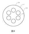
圖4示出了根據本技術的實施方案的配接器220的示意性部分俯視平面圖。如前所述,第一中央通道219可以從配接器220的第一端部217延伸,並且可以部分地延伸穿過配接器。配接器可以限定中央通道的底板,所述底板可以具有圓柱形輪廓,並且可以過渡到多個孔225,所述多個孔225穿過配接器朝向第二端部延伸,如上所述。類似於孔214,孔225可以圍繞穿過配接器220的中心軸線分佈,並且可以圍繞所述中心軸線等距地定位。配接器220可以限定穿過配接器的任何數量的孔,並且在一些實施方案中可以限定比隔離器215中更多孔。附加的孔可以增加與添加的前驅物的混合。如前所述,混合通道可以將附加的前驅物朝向配接器的第一端部輸送,並輸送到第一中央通道219中。在這種實施方案中,圖4和圖5的視圖將顛倒。4 shows aschematic partial top plan view of an
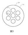
圖5示出了根據本技術的一些實施方案的穿過圖2的線A-A的配接器220的示意性剖視圖。圖5可示出穿過第二中央通道221的視圖,所述視圖可示出穿過先前所述的第二部分226到混合通道的出口。如圖所示,第二部分226可以在孔225之間延伸,並且可以沿著配接器220的中心軸線朝向配接器的第二端部延伸。另外,如上所述,在第二部分226朝向第一中央通道219延伸的實施方案中,圖4和圖5的視圖應顛倒,並且來自遠端電漿單元的混合前驅物和通過配接器220中的埠引入的前驅物將在預混合後從孔225中離開。FIG.5 shows a schematic cross-sectional view of
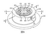
圖6示出了根據本技術的一些實施方案的混合歧管235的示意性透視圖。如前所述,混合歧管235可以限定穿過混合歧管的中央通道238,所述中央通道238可以將混合前驅物從配接器輸送到處理腔室。混合歧管235還可以包括許多特徵,所述特徵允許引入可以與先前混合的前驅物混合的附加的前驅物。如前所述,一個或多個埠239可以提供用於將前驅物引入混合歧管235的通路。埠239可以通往如圖2所示的通道,所述通道可以延伸到在混合歧管235的第一表面236中限定的一個或多個溝槽中。FIG.6 shows a schematic perspective view of a mixing
溝槽可限定在混合歧管235的第一表面236中,當混合歧管與先前討論的間隔件230耦接時,所述溝槽可形成至少部分隔離的通道。第一溝槽240可以圍繞中央通道238形成。第一溝槽240可以是環形形狀的,並且可以由從中心軸線穿過混合歧管235的內半徑以及外半徑表徵。內半徑可以由第一內側壁605限定,所述第一內側壁605可以限定延伸穿過混合歧管235的中央通道238的頂部部分。第一溝槽240的外半徑可以由第一外側壁610限定,所述第一外側壁610可以位於第一內側壁605的徑向外側。第一溝槽240可以提供通過第一內側壁605到中央通道238的流體通路。例如,第一內側壁605可以限定穿過第一內側壁605的多個孔606。孔606可以圍繞第一內側壁605分佈以提供多個進入位置,以便將另外的前驅物輸送到中央通道238中。Grooves can be defined in the
第一內側壁605可以由從第一表面236朝向第一溝槽240斜面或倒角的表面表徵。在實施方案中,可以形成倒角輪廓,所述倒角輪廓可以沿第一表面236保持第一內側壁605的至少一部分,所述第一表面236可用於與先前討論的間隔件230耦接。倒角還可以提供進一步的橫向間隔,以防止在第一溝槽240與中央通道238之間的第一表面上洩漏。孔606可以限定為穿過倒角部分,並且可以限定為成一定角度,諸如與倒角部分的平面成直角,或者以某一其他角度穿過第一內側壁605。The first
混合歧管235可限定第二溝槽241,所述第二溝槽241從第一溝槽240徑向向外形成。在一些實施方案中,第二溝槽241也可以是環形的,並且中心通道238、第一溝槽240和第二溝槽241可以圍繞穿過混合歧管235的中心軸線同心地對準。第二溝槽241可以經由先前所述的通道243與埠239流體耦接。通道243可以延伸到第二溝槽241內的一個或多個位置,並且可以從溝槽的基部通入第二溝槽241,但是在其他實施方案中,通道243也可以通過溝槽的側壁通入溝槽241。通過從第二溝槽241下方通入,可以使第二溝槽241的深度最小化,這可以減小所形成的通道的容積,並且可以限制所輸送的前驅物的擴散以增加輸送的均勻性。The mixing
第二溝槽241可以限定在第一外側壁610與外半徑之間,所述第一外側壁610可以替代地為第二內側壁,所述外半徑由混合歧管235的主體限定。在實施方案中,第一外側壁610可以沿著混合歧管235的第一表面236限定第一溝槽240和第二溝槽241中的每一個。第一外側壁610可以由沿第一表面236在第一外側壁的靠近第二溝槽241的一側上的傾斜或倒角輪廓表徵,所述輪廓類似於第一內側壁605的輪廓。第一外側壁610還可以限定穿過壁限定的多個孔608,以在第二溝槽241與第一溝槽240之間提供流體通路。孔608可以限定在沿著第一外側壁610或穿過第一外側壁610的任何位置,並且可以限定為穿過倒角部分,類似於穿過第一內側壁605的孔。因此,通過埠239輸送的前驅物可以流入第二溝槽241,可以穿過孔608進入第一溝槽240,並且可以穿過孔606進入中央通道238,前驅物可以與通過配接器220輸送的前驅物在所述中央通道238中混合。The
孔608可以包括穿過第一外側壁610限定的任何數目的孔,並且孔606可以包括穿過第一內側壁605限定的任何數目的孔。在一些實施方案中,穿過每個壁的孔的數量可以不相等。例如,在一些實施方案中,穿過第一內側壁605的孔606的數量可以大於穿過第一外側壁的孔608的數量,並且在一些實施方案中,孔606的數量可以是孔608的數量的兩倍或更多。另外,孔608可以從孔606徑向偏移,使得沒有孔608通過從混合歧管235的中心軸線延伸的半徑與任何孔606成一直線。這種孔和通道設計可以提供通過混合歧管的遞迴流動,從而改善附加的前驅物到中央通道238中的輸送,並且可以通過每個孔606提供更均勻的輸送。混合歧管235還可以限定附加的溝槽615,所述附加的溝槽615可以在第二溝槽241的徑向外側,並且可以被配置為用於接納彈性體元件或o形環。
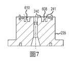
圖7示出了根據本技術的一些實施方案穿過圖6的線B-B的混合歧管235的示意性橫截面視圖。橫截面將孔608示出為它們限定為穿過第一外側壁610以提供從第二溝槽241到第一溝槽240的流體通路。另外,圖7示出了一些實施方案,在所述實施方案中孔608彼此間隔開全直徑穿過第一外側壁。孔608還大致間隔開,使得埠239在兩個孔608之間等距地間隔開。先前描述的通道243可以在類似位置處進入第二溝槽241,以與每個孔608具有相等或基本上相等的距離。FIG.7 shows a schematic cross-sectional view of mixing
圖8示出了根據本技術的一些實施方案穿過圖6的線C-C的混合歧管235的示意性橫截面視圖。橫截面將孔606示出為它們限定為穿過第一內側壁605以提供從第一溝槽240到中央通道238的流體通路。孔606以及孔608可以分別延伸穿過第一內側壁和第一外側壁的倒角部分,並且可以以垂直於倒角角度的角度延伸,或者以某一其他傾斜角度延伸。通過包括穿過特徵(諸如第一外側壁610)的傾斜角度,輸送可以提供在前驅物上升以流過下一組孔之前進一步分佈前驅物的流動。這還可以限制形成孔的加工效果,或者以其他方式損壞第一表面236。混合歧管235可以提供這樣的設計,所述設計提供前驅物與延伸穿過中央通道238的一種或多種前驅物的更均勻混合。FIG.8 shows a schematic cross-sectional view of mixing
圖9示出了根據本技術的一些實施方案的通過處理腔室輸送前驅物的方法900的操作。方法900可以在系統200中執行,並且可以允許改進的腔室外部的前驅物混合,同時保護部件免受蝕刻劑損壞。雖然腔室的部件可以暴露於可以隨時間推移而導致磨損的蝕刻劑,但是本技術可以將這些部件限制為可以更容易地更換和維修的部件。例如,本技術可以限制遠端電漿單元的內部部件的暴露,這可以允許將特定保護施加到遠端電漿單元。FIG.9 illustrates operations of a
方法900可以包括在操作905中形成含氟前驅物的遠程電漿。可以將前驅物輸送到待離解的遠端電漿單元,以產生電漿流出物。在實施方案中,遠端電漿單元可以塗覆有或襯有氧化物或其他可以承受與含氟流出物接觸的材料。在實施方案中,除了載氣之外,不可通過遠端電漿單元輸送其他蝕刻劑前驅物,這可以保護所述單元免受損壞,並且允許調整電漿電力/功率以提供前驅物的特定離解,因為這可以有益於正在執行的特定處理。被配置為用於產生不同蝕刻劑的電漿流出物的其他實施方案可以襯有不同的材料,所述不同的材料可以對所述前驅物或前驅物的組合是惰性的。
在操作910處,可使含氟前驅物的電漿流出物流入與遠端電漿單元耦接的配接器中。在操作915處,可使含氫前驅物流入配接器中。配接器可以被配置為用於在配接器內提供含氟前驅物與含氫前驅物的混合,以在操作920處產生第一混合物。在操作925處,可以使第一混合物從配接器流入混合歧管中。在操作930處,可以使第三前驅物流入混合歧管中。第三前驅物可包括附加的含氫前驅物、附加的含鹵素前驅物,或前驅物的其他組合。混合歧管可以被配置為用於執行第三前驅物與第一混合物的第二混合階段,所述第二混合階段可以產生第二混合物935。At
隨後,可以將包括所有三種前驅物的第二混合物從混合歧管輸送到半導體處理腔室中。如前所述,其他地方描述的附加部件可用於控制蝕刻劑的輸送和分佈。應理解,所識別的前驅物僅是用於所述腔室中的合適前驅物的示例。貫穿本公開內容討論的腔室和材料可以用於任何數量的其他處理操作,所述其他處理操作可以受益於分離前驅物和在將前驅物輸送到處理腔室中之前混合它們。Subsequently, a second mixture comprising all three precursors can be delivered from the mixing manifold into the semiconductor processing chamber. As previously mentioned, additional components described elsewhere can be used to control the delivery and distribution of the etchant. It should be understood that the precursors identified are only examples of suitable precursors for use in the chamber. The chambers and materials discussed throughout this disclosure can be used in any number of other processing operations that can benefit from separating precursors and mixing them prior to delivery into the processing chamber.
在前面的描述中,出於解釋的目的,已經闡述了許多細節以提供對本技術的各個實施方案的理解。然而,對於本領域技術人員將顯而易見的是,某些實施方案可以在沒有這些細節中的一些或者具有另外細節的情況下實踐。In the foregoing description, for the purposes of explanation, numerous details have been set forth in order to provide an understanding of various embodiments of the present technology. However, it will be apparent to those skilled in the art that certain embodiments may be practiced without some of these details or with additional details.
已經公開了幾個實施方案,但是本領域的技術人員將認識到,在不悖離實施方案的精神的情況下,可以使用各種修改、替代構造和等同物。另外,沒有描述許多眾所周知的製程和元件,以避免不必要地模糊本技術。因此,以上描述不應被視為限制本技術的範圍。Several embodiments have been disclosed, but those skilled in the art will recognize that various modifications, alternative constructions and equivalents may be used without departing from the spirit of the embodiments. Additionally, many well-known processes and components have not been described in order to avoid unnecessarily obscuring the technology. Accordingly, the above description should not be construed as limiting the scope of the present technology.
在提供值的範圍的情況下,應理解,除非上下文另有明確規定,否則在所述範圍的上限與下限之間的每個居中值,至下限單位的最小分數,也被具體公開。包含在規定範圍內的任何規定值或未規定的中間值與該規定範圍內的任何其他規定值或中間值之間的任何較窄範圍。這些較小範圍的上限和下限可以獨立地包括或排除在該範圍內,並且其中所述較小範圍內包括上限和下限之一、不包括上限和下限、以及上限和下限都包括的每個範圍也包括在本技術內,受限於所述範圍中任何被具體排除的極限。在所述範圍包括所述極限值中的一個或兩個的情況下,還包括排除那些所包括的極限值中的任一個或兩個的範圍。Where a range of values is provided, it is to be understood that, unless the context clearly dictates otherwise, each intervening value between the upper and lower limit of the stated range, to the minimum fraction of the unit of the lower limit, is also specifically disclosed. Include any narrower range between any stated or unspecified intervening value in a stated range and any other stated or intervening value in that stated range. The upper and lower limits of these smaller ranges may independently be included or excluded in the range, and each range in which the smaller ranges include one of the upper and lower limits, exclusive of the upper and lower limits, and both upper and lower limits Also included within the present technology are subject to any specifically excluded limit in the stated range. Where the stated range includes one or both of the stated limits, ranges excluding either or both of those included limits are also included.
如本文中和所附申請專利範圍中使用的,單數形式「一」、「一個」和「所述」包括多個指代物,除非上下文另外明確指出。因此,例如,提及「一層」包括多個此類層,並且提及「該前驅物」包括提及一種或多種前驅物及本領域的技術人員已知的其等同物,等等。As used herein and in the appended claims, the singular forms "a," "an," and "the" include plural referents unless the context clearly dictates otherwise. Thus, for example, reference to "a layer" includes a plurality of such layers, and reference to "the precursor" includes reference to one or more precursors and equivalents thereof known to those skilled in the art, and the like.
此外,當在本說明書和以下申請專利範圍中使用時,詞語「包括」、「含有」、「含有」和「包含」旨在指明存在所敘述的特徵、整數、部件或操作,但它們不排除存在或添加一個或多個其他特徵、整數、部件、操作、動作或組。Furthermore, when used in this specification and the following claims, the words "including", "containing", "containing" and "comprising" are intended to indicate the presence of the recited features, integers, components or operations, but they do not exclude One or more other features, integers, components, operations, actions or groups are present or added.
100:處理系統102:前開式晶圓傳送盒104:機械臂106:保持區域110:第二機械臂200:示例性處理系統205:處理腔室210:遠端電漿單元211:第一端部212:第二端部213:通道214:孔215:隔離器217:第一端部218:第二端部219:中央通道220:配接器221:第二中央通道222:埠223:混合通道224:第一部分225:孔226:第二部分226a:第二部分226b:第二部分227:溝槽228:溝槽230:間隔件232:中央孔235:混合歧管236:第一端部237:第二端部238:中央通道239:埠240:第一溝槽241:第二溝槽242:第一部分243:通道246:擴口區段247:出口248:加熱器250:氣體箱252:腔室入口253:第一表面254:中央通道255:第二表面257:容積258:容積260:區隔板263:孔265:上升環形區段266:下降環形區段270:面板272:第一表面273:凸緣274:第二表面275:第三容積280:離子抑制元件290:間隔件605:第一內側壁606:孔608:孔610:第一外側壁615:溝槽900:方法905-935:操作108a-f:基板處理腔室109a-c:串聯區段226a-b:第二部分100: Handling Systems102: Front opening wafer transfer box104: Robotic Arm106: Keep Area110: The second robotic arm200: Exemplary Processing System205: Processing Chamber210: Remote Plasma Unit211: First End212: Second End213: Channel214: Hole215: Isolator217: First End218: Second End219: Central Passage220: Adapter221: Second Central Channel222: port223: Mixed channel224: Part One225: Hole226: Part II226a: Part II226b: Part II227: Groove228: Groove230: Spacer232: Central hole235: Mixing Manifold236: First End237: Second End238: Central Channel239: port240: First groove241: Second groove242: Part One243: Channel246: Flare section247:Export248: Heater250: Gas Box252: Chamber entrance253: First Surface254: Central Channel255: Second Surface257: Volume258: Volume260: Zone partitions263: Hole265: Ascending Ring Section266: Descending Ring Section270: Panel272: First Surface273: Flange274: Second Surface275: The third volume280: Ion suppression element290: Spacer605: First inner side wall606: Hole608: Hole610: First outer side wall615: Groove900: Method905-935: Operations108a-f: Substrate processing chambers109a-c: Tandem segment226a-b: Part II
對所公開的技術的性質和優點的進一步理解可通過參考說明書的剩餘部分和附圖來實現。A further understanding of the nature and advantages of the disclosed technology may be realized by reference to the remainder of the specification and the accompanying drawings.
圖1示出了根據本技術的一些實施方案的示例性處理系統的俯視平面圖。1 illustrates a top plan view of an exemplary processing system in accordance with some embodiments of the present technology.
圖2示出了根據本技術的一些實施方案的示例性處理腔室的示意性橫截面視圖。2 shows a schematic cross-sectional view of an exemplary processing chamber in accordance with some embodiments of the present technology.
圖3示出了根據本技術的一些實施方案的隔離器的示意性部分仰視平面圖。3 illustrates a schematic partial bottom plan view of an isolator in accordance with some embodiments of the present technology.
圖4示出了根據本技術的一些實施方案的配接器的示意性部分俯視平面圖。4 illustrates a schematic partial top plan view of an adapter in accordance with some embodiments of the present technology.
圖5示出了根據本技術的一些實施方案的穿過圖2的線A-A的配接器的示意性橫截面視圖。5 shows a schematic cross-sectional view of the adapter through line A-A of FIG. 2, according to some embodiments of the present technology.
圖6示出了根據本技術的一些實施方案的混合歧管的示意性透視圖。6 shows a schematic perspective view of a mixing manifold in accordance with some embodiments of the present technology.
圖7示出了根據本技術的一些實施方案穿過圖6的線B-B的混合歧管的示意性橫截面視圖。7 shows a schematic cross-sectional view of a mixing manifold through line B-B of FIG. 6 in accordance with some embodiments of the present technology.
圖8示出了根據本技術的一些實施方案穿過圖6的線C-C的混合歧管的示意性橫截面視圖。8 shows a schematic cross-sectional view of a mixing manifold through line C-C of FIG. 6 in accordance with some embodiments of the present technology.
圖9示出了根據本技術的一些實施方案的通過處理系統輸送前驅物的方法的操作。9 illustrates operation of a method of delivering a precursor through a processing system in accordance with some embodiments of the present technology.
所述附圖中的若干附圖被包括作為示意圖。應理解,附圖僅用於說明目的,並且除非特別說明為按比例的,否則不應視為按比例的。另外,作為示意圖,提供附圖是為了幫助理解,並且附圖可不包括與真實表示相比的所有態樣或資訊,並且可包括用於說明性目的的誇大材料。Several of the figures are included as schematic representations. It should be understood that the drawings are for illustration purposes only and should not be considered to scale unless specifically stated to be to scale. Additionally, the drawings are provided as schematic diagrams to aid understanding and may not include all aspects or information compared to actual representations and may include exaggerated material for illustrative purposes.
在附圖中,相似的部件和/或特徵可以具有相同的附圖標記。此外,可以通過使附圖標記後接區分相似部件的字母來區分相同類型的各種部件。如果在說明書中僅使用第一附圖標記,則描述適用於具有相同第一參考標號的任何一個類似部件,而與字母無關。In the drawings, similar components and/or features may have the same reference numerals. Furthermore, various components of the same type may be distinguished by following a reference number with a letter that distinguishes similar components. If only the first reference number is used in the description, the description applies to any one similar part having the same first reference number, regardless of the letter.
國內寄存資訊 (請依寄存機構、日期、號碼順序註記)無Domestic storage information (please note in the order of storage institution, date and number)none
國外寄存資訊 (請依寄存國家、機構、日期、號碼順序註記)無Foreign deposit information (please mark in the order of deposit country, institution, date and number)none
200:示例性處理系統200: Exemplary Processing System
205:處理腔室205: Processing Chamber
210:遠端電漿單元210: Remote Plasma Unit
211:第一端部211: First End
212:第二端部212: Second End
213:通道213: Channel
214:孔214: Hole
215:隔離器215: Isolator
217:第一端部217: First End
218:第二端部218: Second End
219:中央通道219: Central Passage
220:配接器220: Adapter
221:第二中央通道221: Second Central Channel
222:埠222: port
223:混合通道223: Mixed channel
224:第一部分224: Part One
225:孔225: Hole
226a:第二部分226a: Part II
226b:第二部分226b: Part II
227:溝槽227: Groove
228:溝槽228: Groove
230:間隔件230: Spacer
232:中央孔232: Central hole
235:混合歧管235: Mixing Manifold
236:第一端部236: First End
237:第二端部237: Second End
238:中央通道238: Central Channel
239:埠239: port
240:第一溝槽240: First groove
241:第二溝槽241: Second groove
242:第一部分242: Part One
243:通道243: Channel
246:擴口區段246: Flare section
247:出口247:Export
248:加熱器248: Heater
250:氣體箱250: Gas Box
252:腔室入口252: Chamber entrance
253:第一表面253: First Surface
254:中央通道254: Central Channel
255:第二表面255: Second Surface
257:容積257: Volume
258:容積258: Volume
260:區隔板260: Zone partitions
263:孔263: Hole
265:上升環形區段265: Ascending Ring Section
266:下降環形區段266: Descending Ring Section
270:面板270: Panel
272:第一表面272: First Surface
273:凸緣273: Flange
274:第二表面274: Second Surface
275:第三容積275: The third volume
280:離子抑制元件280: Ion suppression element
290:蓋間隔件290: Cover Spacer
Claims (20)
Translated fromChinesePriority Applications (1)
| Application Number | Priority Date | Filing Date | Title |
|---|---|---|---|
| TW110114252ATWI768838B (en) | 2019-04-09 | 2019-04-09 | Semiconductor processing system component |
Applications Claiming Priority (1)
| Application Number | Priority Date | Filing Date | Title |
|---|---|---|---|
| TW110114252ATWI768838B (en) | 2019-04-09 | 2019-04-09 | Semiconductor processing system component |
Publications (2)
| Publication Number | Publication Date |
|---|---|
| TW202141625A TW202141625A (en) | 2021-11-01 |
| TWI768838Btrue TWI768838B (en) | 2022-06-21 |
Family
ID=80783270
Family Applications (1)
| Application Number | Title | Priority Date | Filing Date |
|---|---|---|---|
| TW110114252ATWI768838B (en) | 2019-04-09 | 2019-04-09 | Semiconductor processing system component |
Country Status (1)
| Country | Link |
|---|---|
| TW (1) | TWI768838B (en) |
Citations (5)
| Publication number | Priority date | Publication date | Assignee | Title |
|---|---|---|---|---|
| US6464795B1 (en)* | 1999-05-21 | 2002-10-15 | Applied Materials, Inc. | Substrate support member for a processing chamber |
| US20130284700A1 (en)* | 2012-04-26 | 2013-10-31 | Applied Materials, Inc. | Proportional and uniform controlled gas flow delivery for dry plasma etch apparatus |
| US20160168705A1 (en)* | 2014-12-10 | 2016-06-16 | Lam Research Corporation | Inlet for effective mixing and purging |
| US9574268B1 (en)* | 2011-10-28 | 2017-02-21 | Asm America, Inc. | Pulsed valve manifold for atomic layer deposition |
| TW201805473A (en)* | 2016-06-01 | 2018-02-16 | Asm Ip控股公司 | Semiconductor processing device and deposition method |
- 2019
- 2019-04-09TWTW110114252Apatent/TWI768838B/enactive
Patent Citations (5)
| Publication number | Priority date | Publication date | Assignee | Title |
|---|---|---|---|---|
| US6464795B1 (en)* | 1999-05-21 | 2002-10-15 | Applied Materials, Inc. | Substrate support member for a processing chamber |
| US9574268B1 (en)* | 2011-10-28 | 2017-02-21 | Asm America, Inc. | Pulsed valve manifold for atomic layer deposition |
| US20130284700A1 (en)* | 2012-04-26 | 2013-10-31 | Applied Materials, Inc. | Proportional and uniform controlled gas flow delivery for dry plasma etch apparatus |
| US20160168705A1 (en)* | 2014-12-10 | 2016-06-16 | Lam Research Corporation | Inlet for effective mixing and purging |
| TW201805473A (en)* | 2016-06-01 | 2018-02-16 | Asm Ip控股公司 | Semiconductor processing device and deposition method |
Also Published As
| Publication number | Publication date |
|---|---|
| TW202141625A (en) | 2021-11-01 |
Similar Documents
| Publication | Publication Date | Title |
|---|---|---|
| US11515179B2 (en) | Semiconductor processing chamber multistage mixing apparatus | |
| CN113287185B (en) | Process chamber mixing system | |
| US10964512B2 (en) | Semiconductor processing chamber multistage mixing apparatus and methods | |
| TWI795404B (en) | Semiconductor processing chamber and system for multiple precursor flow | |
| TWI858421B (en) | Semiconductor processing chamber for improved precursor flow | |
| TWI783169B (en) | Selective material removal | |
| CN210129482U (en) | Semiconductor processing chamber multi-stage mixing equipment | |
| KR102255071B1 (en) | Semiconductor processing chamber multistage mixing apparatus | |
| TWI728337B (en) | Semiconductor processing system and method of delivering precursors through semiconductor processing system | |
| TWI768838B (en) | Semiconductor processing system component | |
| JP6736720B1 (en) | Semiconductor processing chamber Multi-stage mixing device | |
| TWM594798U (en) | Semiconductor processing system | |
| CN111799143B (en) | Multistage mixing apparatus for semiconductor processing chamber | |
| JP7071445B2 (en) | Semiconductor processing chamber multi-stage mixing equipment | |
| KR102223806B1 (en) | Semiconductor processing chamber multistage mixing apparatus | |
| TWM599997U (en) | Semiconductor processing system component |