TWI767640B - A wrench and a manufacturing method for the same - Google Patents
A wrench and a manufacturing method for the sameDownload PDFInfo
- Publication number
- TWI767640B TWI767640BTW110111900ATW110111900ATWI767640BTW I767640 BTWI767640 BTW I767640BTW 110111900 ATW110111900 ATW 110111900ATW 110111900 ATW110111900 ATW 110111900ATW I767640 BTWI767640 BTW I767640B
- Authority
- TW
- Taiwan
- Prior art keywords
- cover plate
- gasket
- washer
- wrench
- head
- Prior art date
Links
- 238000004519manufacturing processMethods0.000titleclaimsabstractdescription12
- 238000000034methodMethods0.000claimsdescription14
- 238000001746injection mouldingMethods0.000claimsdescription13
- 230000002093peripheral effectEffects0.000claimsdescription7
- 238000007789sealingMethods0.000description14
- 239000000428dustSubstances0.000description8
- 239000000084colloidal systemSubstances0.000description7
- 230000000694effectsEffects0.000description7
- 239000004576sandSubstances0.000description7
- 239000007788liquidSubstances0.000description4
- 238000002347injectionMethods0.000description3
- 239000007924injectionSubstances0.000description3
- 238000001816coolingMethods0.000description2
- 238000010586diagramMethods0.000description2
- 238000005516engineering processMethods0.000description2
- 238000000465mouldingMethods0.000description2
- 239000010687lubricating oilSubstances0.000description1
- 239000007769metal materialSubstances0.000description1
- 230000000750progressive effectEffects0.000description1
Images


Classifications
- B—PERFORMING OPERATIONS; TRANSPORTING
- B25—HAND TOOLS; PORTABLE POWER-DRIVEN TOOLS; MANIPULATORS
- B25B—TOOLS OR BENCH DEVICES NOT OTHERWISE PROVIDED FOR, FOR FASTENING, CONNECTING, DISENGAGING OR HOLDING
- B25B23/00—Details of, or accessories for, spanners, wrenches, screwdrivers
- B25B23/0007—Connections or joints between tool parts
- B25B23/0035—Connection means between socket or screwdriver bit and tool
- B—PERFORMING OPERATIONS; TRANSPORTING
- B25—HAND TOOLS; PORTABLE POWER-DRIVEN TOOLS; MANIPULATORS
- B25B—TOOLS OR BENCH DEVICES NOT OTHERWISE PROVIDED FOR, FOR FASTENING, CONNECTING, DISENGAGING OR HOLDING
- B25B13/00—Spanners; Wrenches
- B25B13/46—Spanners; Wrenches of the ratchet type, for providing a free return stroke of the handle
- B25B13/461—Spanners; Wrenches of the ratchet type, for providing a free return stroke of the handle with concentric driving and driven member
- B25B13/462—Spanners; Wrenches of the ratchet type, for providing a free return stroke of the handle with concentric driving and driven member the ratchet parts engaging in a direction radial to the tool operating axis
- B25B13/463—Spanners; Wrenches of the ratchet type, for providing a free return stroke of the handle with concentric driving and driven member the ratchet parts engaging in a direction radial to the tool operating axis a pawl engaging an externally toothed wheel
- B—PERFORMING OPERATIONS; TRANSPORTING
- B25—HAND TOOLS; PORTABLE POWER-DRIVEN TOOLS; MANIPULATORS
- B25B—TOOLS OR BENCH DEVICES NOT OTHERWISE PROVIDED FOR, FOR FASTENING, CONNECTING, DISENGAGING OR HOLDING
- B25B13/00—Spanners; Wrenches
- B25B13/10—Spanners; Wrenches with adjustable jaws
- B25B13/107—Spanners; Wrenches with adjustable jaws composed of a main body with exchangeable inserts
- B—PERFORMING OPERATIONS; TRANSPORTING
- B25—HAND TOOLS; PORTABLE POWER-DRIVEN TOOLS; MANIPULATORS
- B25B—TOOLS OR BENCH DEVICES NOT OTHERWISE PROVIDED FOR, FOR FASTENING, CONNECTING, DISENGAGING OR HOLDING
- B25B13/00—Spanners; Wrenches
- B25B13/46—Spanners; Wrenches of the ratchet type, for providing a free return stroke of the handle
Landscapes
- Engineering & Computer Science (AREA)
- Mechanical Engineering (AREA)
- Details Of Spanners, Wrenches, And Screw Drivers And Accessories (AREA)
- Injection Moulding Of Plastics Or The Like (AREA)
- Pens And Brushes (AREA)
- Dowels (AREA)
Abstract
Description
Translated fromChinese本發明係有關於一種扳手及該扳手之製程。The present invention relates to a wrench and a manufacturing process of the wrench.
按,在一般工業上及日常生活的鎖固作業中,棘輪扳手及扭力扳手等手工具具有可限制轉動角度及轉動扭力之功能,而普遍受到使用,而為了使扳手之驅動件可順利轉動,會在組裝完扳手本體內之棘輪件及棘齒後充填潤滑油,再蓋設一封蓋至扳手本體,且會在封蓋與扳手本體之間設置密封環,以避免外界之沙塵進入扳手本體內部而導致棘輪件及棘齒損壞。Press, in general industrial and daily life locking operations, hand tools such as ratchet wrenches and torque wrenches have the function of limiting the rotation angle and rotation torque, and are widely used, and in order to make the driving part of the wrench rotate smoothly, After assembling the ratchet parts and ratchet teeth in the wrench body, lubricating oil will be filled, and then a cover will be placed on the wrench body, and a sealing ring will be set between the cover and the wrench body to prevent external sand and dust from entering the wrench. damage to the ratchet and ratchet teeth.
然而,在封蓋蓋設於本體並進行鎖固的過程中,容易不慎使密封環相對本體及封蓋滑動,而導致密封環無法有效對位,導致密封環的密封效果不佳,而使外界之沙塵進入扳手本體內部。However, in the process that the cover is installed on the body and locked, it is easy to accidentally slide the sealing ring relative to the body and the cover, so that the sealing ring cannot be effectively aligned, resulting in poor sealing effect of the sealing ring, and The sand and dust from the outside enter the inside of the wrench body.
另外具有一種密封方式,其係為在封蓋與扳手本體之間注入液態膠體,以使封蓋與扳手本體密封。然而,此類注膠方式由於係在膠體為液態時注入,膠體在液態時即被封蓋與扳手本體壓抵並冷卻,而導致無法有效控制膠體冷卻後之形狀,如此同樣會使密封效果不佳,存在極待改善之缺弊。In addition, there is a sealing method, which is to inject liquid colloid between the cover and the wrench body to seal the cover and the wrench body. However, this type of injection method is injected when the colloid is liquid, and the colloid is pressed against and cooled by the cover and the wrench body when the colloid is in a liquid state, so that the shape of the colloid after cooling cannot be effectively controlled, which also makes the sealing effect ineffective. Good, there are shortcomings that need to be improved.
因此,有必要提供一種新穎且具有進步性之扳手及該扳手之製程,以解決上述之問題。Therefore, it is necessary to provide a novel and progressive wrench and the manufacturing process of the wrench to solve the above problems.
本發明之主要目的在於提供一種扳手及該扳手之製程,藉由將第一墊圈及一第二墊圈一體成型於該蓋板,因此在組裝過程中可使該第一墊圈及該第二墊圈準確地蓋設於扳手之本體,且第一墊圈及第二墊圈可維持於特定形狀,透過轉射技術,可依據不同工具之結構需要,設計特殊形狀的墊圈,亦可為專屬形狀,並用在工具內部指定位置成形,藉此用以提高密封效果,並提供產品更多樣化的設計。The main purpose of the present invention is to provide a wrench and a manufacturing process of the wrench. By integrally molding a first washer and a second washer on the cover plate, the first washer and the second washer can be accurately assembled during the assembly process. The ground cover is placed on the body of the wrench, and the first washer and the second washer can be maintained in a specific shape. Through the transfer technology, a special-shaped washer can be designed according to the structural needs of different tools, or a special shape can be used in the tool. The internal designated position is formed to improve the sealing effect and provide more diversified product designs.
為達成上述目的,本發明提供一種扳手,包括一本體及一蓋板,該本體包括一頭部及一握柄,該頭部設有一容置槽,該容置槽內設有一驅動件及一制動件,該制動件抵頂於該驅動件且該驅動件可相對該頭部轉動。該蓋板蓋設於該容置槽,包括一穿孔,該本體與該蓋板其中一者一體設有一第一墊圈及一第二墊圈,該第一墊圈與該第二墊圈夾抵於該本體與該蓋板之間。 為達成上述目的,本發明另提供一種扳手之製程,其係用於製造如上所述的扳手,包括以下步驟:備一包括一頭部及一握柄之本體,將該頭部之一側開設出一容置槽,並將一驅動件可轉動地組裝於該容置槽,以及將一制動件組裝於該容置槽並使該制動件抵頂於該驅動件;備一蓋板,將該蓋板開設一穿孔,該本體與該蓋板其中一者以轉射成型之方式一體成型出一第一墊圈及一第二墊圈;將該蓋板蓋設於該頭部之容置槽,以使該第一墊圈與該第二墊圈夾抵於該本體與該蓋板之間。In order to achieve the above object, the present invention provides a wrench, which includes a main body and a cover plate, the main body includes a head and a handle, the head is provided with an accommodating groove, and the accommodating groove is provided with a driving member and a handle. a braking part, the braking part is pressed against the driving part and the driving part can rotate relative to the head part. The cover plate covers the accommodating groove and includes a through hole. One of the main body and the cover plate is integrally provided with a first gasket and a second gasket. The first gasket and the second gasket are clamped against the main body. between the cover. In order to achieve the above object, the present invention further provides a process for manufacturing a wrench, which is used to manufacture the above-mentioned wrench, comprising the following steps: preparing a body including a head and a handle, and opening one side of the head An accommodating groove is formed, a driving member is rotatably assembled in the accommodating groove, and a braking member is assembled in the accommodating groove and the braking member is pressed against the driving member; The cover plate has a through hole, and one of the main body and the cover plate is integrally formed with a first gasket and a second gasket by means of injection molding; the cover plate is covered on the accommodating groove of the head, so that the first gasket and the second gasket are clamped between the main body and the cover plate.
以下僅以實施例說明本發明可能之實施態樣,然並非用以限制本發明所欲保護之範疇,合先敘明。The following examples only illustrate possible implementations of the present invention, but are not intended to limit the scope of protection of the present invention, and are described together first.
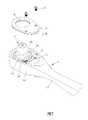
請參考圖1至7,其顯示本發明之第一較佳實施例,本發明之扳手包括一本體1及一蓋板4。Please refer to FIGS. 1 to 7 , which show the first preferred embodiment of the present invention. The wrench of the present invention includes a
該本體1包括一頭部11及一握柄12,該頭部11設有一容置槽13,該容置槽13內設有一驅動件2及一制動件3,該制動件3抵頂於該驅動件2且該驅動件2可相對該頭部11轉動,於本實施例中該扳手為棘輪扳手,該驅動件2具有棘輪,於其它實施例中亦可為扭力扳手或其它種類之扳手。The
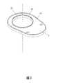
該蓋板4蓋設於該容置槽13,包括一穿孔41,該本體1與該蓋板4其中一者一體設有一第一墊圈42及一第二墊圈43,該第一墊圈42與該第二墊圈43夾抵於該本體1與該蓋板4之間,於本實施例中該蓋板4抵頂於該容置槽13之一側一體設有該第一墊圈42及該第二墊圈43。藉此,當該扳手在進行組裝時,由於該蓋板4一體設有該第一墊圈42及該第二墊圈43,因此可避免蓋板4蓋設於該容置槽13的過程中該第一墊圈42與該第二墊圈43相對該蓋板4移動,因此可使該第一墊圈42與該第二墊圈43有效地密封住該頭部11與該蓋板4之間的間隙,避免外界之沙塵進入該容置槽13內,因此可使本發明之板手具有較好的耐用度,因此本發明於組裝時較方便。於本實施例中該蓋板4藉由二鎖固件15鎖固於該頭部11,於其它實施例中該蓋板亦可直接以卡扣或緊配合之方式固定於該頭部。The
具體而言,該第一墊圈42及該第二墊圈43以轉射成型之方式一體設於該蓋板4,該第一墊圈42環繞於該穿孔41之孔緣,該第二墊圈43環繞於該蓋板4之外周緣,舉例說明,於本實施例中該蓋板4為金屬材質(亦可為硬質塑膠),藉由轉設成型之製造方式可直接將塑膠材質或橡膠材質之該第一墊圈42及該第二墊圈43一體成型於該蓋板4,即可避免在該蓋板4蓋設組接於該本體1的過程中該第一墊圈42及該第二墊圈43相對該蓋板4滑動,透過轉射成型技術,該第一墊圈42及該第二墊圈43可設計為任何形狀,並可依據不同工具之結構需要,設計特殊形狀的墊圈,或可為專屬形狀,並用在工具內部指定位置成形,藉此增加產品多樣化設計。Specifically, the
詳細的說,該第一墊圈42夾抵於該驅動件2與該蓋板4之間,該本體1包括一環壁14,該環壁14圍構出該容置槽13,該第二墊圈43夾抵於該環壁14與該蓋板4之間,於其它實施例中該地一墊圈42與該第二墊圈43亦可相互置換設置位置。Specifically, the
進一步的說,該驅動件2包括相連接之一轉動部21及一驅動部22,該驅動部22穿設於該穿孔41,該轉動部21朝向該蓋板4之一側設有一第一環凹槽23,該第一墊圈42抵頂於該第一環凹槽23內。Further, the
本發明另提供一種扳手之製程,其係用於製造如上所述的扳手,包括以下步驟:備一包括一頭部11及一握柄12之本體1,將該頭部11之一側開設出一容置槽13,並將一驅動件2可轉動地組裝於該容置槽13,以及將一制動件3組裝於該容置槽13並使該制動件3抵頂於該驅動件2;備一蓋板4,將該蓋板4開設一穿孔41,該本體1與該蓋板4其中一者以轉射成型之方式一體成型出一第一墊圈42及一第二墊圈43;將該蓋板4蓋設於該頭部11之容置槽13,以使該第一墊圈42與該第二墊圈43夾抵於該本體1與該蓋板4之間,於本實施例中係於該蓋板4之一側以轉射成型之方式一體成型出該第一墊圈42及該第二墊圈43。The present invention further provides a manufacturing process of a wrench, which is used to manufacture the wrench as described above, including the following steps: preparing a
藉由上述之製程,即可製造出一體設有該第一墊圈42及該第二墊圈43之蓋板4,該扳手在組裝過程中即可避免蓋板4之該第一墊圈42與該第二墊圈43相對該蓋板4移動,故可使該第一墊圈42與該第二墊圈43有效地密封住該頭部11與該蓋板4之間的間隙,避免外界之沙塵進入該容置槽13內,因此可使本發明之板手具有較好的耐用度,藉由上述實施例更可證明,本發明之製程可將專屬形狀的墊圈,運用在各個手工具零件的指定位置,或者搭配手工具內部結構的配置需求,成型特殊墊圈造型,不僅強化密封強度,更能創造多樣式手工具設計型態。Through the above process, the
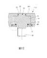
詳細的說,於本實施例中另備一第一模具51及一第二模具52,該第一模具51及該第二模具52壓抵於該蓋板4,並將胚料(如融熔狀橡膠或塑料)注入於該第一模具51及該第二模具52之間以轉射成型出該第一墊圈42及該第二墊圈43於該蓋板4之一側。藉由該第一模具51及該第二模具52之模穴之形狀可使該第一墊圈42及該第二墊圈43以特定形狀成型於該蓋板4,該第一墊圈42及該第二墊圈43在未受到該蓋板4及該本體1之夾迫時係維持特定形狀,待受到該蓋板4及該本體1之夾迫時方變形,因此具有較佳地密封效果,且在成型出第一墊圈42及該第二墊圈43前可配合該蓋板4及該本體1之形狀而改變,以適用於不同規格之蓋板4及該本體1。相較於習知注膠方式[係在膠體為液態時注入且被封蓋與扳手本體壓抵並冷卻,而導致無法有效控制膠體冷卻後之形狀,如此同樣會使密封效果不佳],本發明之藉由該第一模具51及該第二模具52之模穴之形狀可使該第一墊圈42及該第二墊圈43以特定形狀成型於該蓋板4具有較好地密封性,且可成型於指定位置,以提供產品更多樣化的設計。In detail, in this embodiment, a
請參考圖8至9,於本發明之第二實施例中,該第一環凹槽23鄰近於該驅動部22,該第一環凹槽23之外周壁朝向該蓋板4之一端設有一倒角24,第一墊圈42A一體設有一延伸段431,該延伸段431伸入該倒角24與該蓋板4之間之缺口,以具有更好地密封效果,避免外界之沙塵進入至該缺口進入。Referring to FIGS. 8 to 9 , in the second embodiment of the present invention, the first
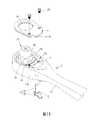
請參考圖10,於本發明之第三實施例中,該第一墊圈42及該第二墊圈43不一體成型於該蓋板4,該本體1一體成型設有該第一墊圈42及該第二墊圈43,於本實施例中係以轉射成型之方式一體成型於該本體1之環壁14及該第一環凹槽23,同樣地可使該第一墊圈42與該第二墊圈43有效地密封住該頭部11與該蓋板4之間的間隙。Referring to FIG. 10 , in the third embodiment of the present invention, the
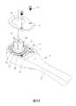
請參考圖11及12,於本發明之第四實施例中,該控制件6包括一切換件61及一撥鈕62,該切換件61可轉動地插設於該頭部11A,該撥鈕62橫向地延伸於該切換件61遠離該頭部11A之一端,本實施例中該扳手為棘輪扳手,藉由撥動該撥鈕62控制該切換件61轉動以調整該棘輪扳手為順時針空轉或逆時針空轉,該切換件61之外周壁以轉射成型之方式一體成型出一第三墊圈71,該第三墊圈71夾抵於該切換件61與該頭部11A之間,以避免外界之沙塵進入該頭部11A內。11 and 12, in the fourth embodiment of the present invention, the
另外,驅動件2A之該轉動部21遠離該驅動部22之一端凸設有一凸柱25,該頭部11A設有一頂板111,該凸柱25可轉動地插設於該頂板111,該凸柱25之外周壁以轉射成型之方式一體成型出一第四墊圈72,該第四墊圈72夾抵於該凸柱25與該頂板111之間,以避免外界之沙塵進入該頭部11A內。In addition, a protruding
綜上,本發明之扳手及該扳手之製程,當該扳手在進行組裝時,由於該蓋板一體設有該第一墊圈及該第二墊圈,因此可避免蓋板蓋設於該容置槽的過程中該第一墊圈與該第二墊圈相對該蓋板移動,因此可使該第一墊圈與該第二墊圈有效地密封住該頭部與該蓋板之間的間隙,避免外界之沙塵進入該容置槽內,因此可使本發明之板手具有較好的耐用度,且第一墊圈及第二墊圈可維持於特定形狀以提高密封效果及成型於指定位置,以提供產品更多樣化的設計。In conclusion, in the wrench and the manufacturing process of the wrench of the present invention, when the wrench is being assembled, since the cover plate is integrally provided with the first washer and the second washer, the cover plate can be prevented from being covered in the accommodating groove During the process, the first gasket and the second gasket move relative to the cover plate, so that the first gasket and the second gasket can effectively seal the gap between the head and the cover plate to avoid external sand Dust can enter the accommodating groove, so the wrench of the present invention can have better durability, and the first gasket and the second gasket can be maintained in a specific shape to improve the sealing effect and be formed in a designated position to provide better product quality. Diverse designs.
1:本體 11, 11A:頭部 111:頂板 12:握柄 13:容置槽 14:環壁 15:鎖固件 2, 2A:驅動件 21:轉動部 22:驅動部 23:第一環凹槽 24:倒角 25:凸柱 3:制動件 4:蓋板 41:穿孔 42, 42A:第一墊圈 43:第二墊圈 431:延伸段 51:第一模具 52:第二模具 6:控制件 61:切換件 62:撥鈕 71:第三墊圈 72:第四墊圈1:
圖1為本發明第一較佳實施例之示意圖。 圖2為本發明第一較佳實施例之分解圖。 圖3為本發明第一較佳實施例之局部立體圖。 圖4為本發明第一較佳實施例之側面剖視圖。 圖5為圖4之局部放大圖。 圖6及圖7為本發明第一較佳實施例之封蓋製程示意圖。 圖8為本發明第二較佳實施例之側面剖視圖。 圖9為圖8之局部放大圖。 圖10為本發明第三較佳實施例之分解圖。 圖11為本發明第四較佳實施例之分解圖。 圖12為本發明第三較佳實施例之側面剖視圖。FIG. 1 is a schematic diagram of a first preferred embodiment of the present invention. FIG. 2 is an exploded view of the first preferred embodiment of the present invention. 3 is a partial perspective view of the first preferred embodiment of the present invention. 4 is a side sectional view of the first preferred embodiment of the present invention. FIG. 5 is a partial enlarged view of FIG. 4 . 6 and 7 are schematic diagrams of a capping process according to the first preferred embodiment of the present invention. 8 is a side sectional view of the second preferred embodiment of the present invention. FIG. 9 is a partial enlarged view of FIG. 8 . FIG. 10 is an exploded view of the third preferred embodiment of the present invention. FIG. 11 is an exploded view of the fourth preferred embodiment of the present invention. 12 is a side sectional view of the third preferred embodiment of the present invention.
1:本體1: Ontology
11:頭部11: Head
12:握柄12: Grip
13:容置槽13: accommodating slot
14:環壁14: Ring Wall
15:鎖固件15: Lock firmware
2:驅動件2: Driver
21:轉動部21: Rotary part
22:驅動部22: Drive Department
23:第一環凹槽23: The first ring groove
3:制動件3: Brakes
4:蓋板4: Cover
41:穿孔41: Perforation
43:第二墊圈43: Second washer
Claims (10)
Translated fromChinesePriority Applications (3)
| Application Number | Priority Date | Filing Date | Title |
|---|---|---|---|
| TW110111900ATWI767640B (en) | 2021-03-31 | 2021-03-31 | A wrench and a manufacturing method for the same |
| DE102022100692.1ADE102022100692B4 (en) | 2021-03-31 | 2022-01-13 | Wrench and manufacturing process of this wrench |
| US17/585,918US11787019B2 (en) | 2021-03-31 | 2022-01-27 | Wrench and method for manufacturing the same |
Applications Claiming Priority (1)
| Application Number | Priority Date | Filing Date | Title |
|---|---|---|---|
| TW110111900ATWI767640B (en) | 2021-03-31 | 2021-03-31 | A wrench and a manufacturing method for the same |
Publications (2)
| Publication Number | Publication Date |
|---|---|
| TWI767640Btrue TWI767640B (en) | 2022-06-11 |
| TW202239536A TW202239536A (en) | 2022-10-16 |
Family
ID=83103826
Family Applications (1)
| Application Number | Title | Priority Date | Filing Date |
|---|---|---|---|
| TW110111900ATWI767640B (en) | 2021-03-31 | 2021-03-31 | A wrench and a manufacturing method for the same |
Country Status (3)
| Country | Link |
|---|---|
| US (1) | US11787019B2 (en) |
| DE (1) | DE102022100692B4 (en) |
| TW (1) | TWI767640B (en) |
Families Citing this family (2)
| Publication number | Priority date | Publication date | Assignee | Title |
|---|---|---|---|---|
| TWI799085B (en)* | 2022-01-14 | 2023-04-11 | 優鋼機械股份有限公司 | Anti-vibration ratchet wrench |
| TWI854863B (en)* | 2023-10-17 | 2024-09-01 | 暘陞精密科技有限公司 | Hand tool drive head structure |
Citations (13)
| Publication number | Priority date | Publication date | Assignee | Title |
|---|---|---|---|---|
| US4347767A (en)* | 1981-01-06 | 1982-09-07 | Gentiluomo Joseph A | Ratcheting device |
| TW404310U (en)* | 1999-07-22 | 2000-09-01 | Jeng Jin Shuen | Magnetic socket structure improvement |
| TWM377293U (en)* | 2009-12-07 | 2010-04-01 | jia-hui Peng | Electric ratchet wrench with dual-torque output |
| TWI345512B (en)* | 2009-01-23 | 2011-07-21 | ||
| TW201311401A (en)* | 2011-09-01 | 2013-03-16 | American Grease Stick Co | Wrench ratchet mechanisms and wrenches |
| TWM477348U (en)* | 2014-01-14 | 2014-05-01 | William Tools Co Ltd | Structure of gourd head ratchet wrench |
| US9038505B2 (en)* | 2013-07-28 | 2015-05-26 | Ya-Lan He | Wrench |
| TWM510820U (en)* | 2015-06-08 | 2015-10-21 | Chia-Ke Hung | Ratchet wrench with dustproof function |
| CN106881677A (en)* | 2015-12-15 | 2017-06-23 | 艾沛克斯工具(香港)有限公司 | Ratchet spanner with dustproof construction |
| CN107614203A (en)* | 2015-03-16 | 2018-01-19 | 凯文·戴恩 | reversible wrench |
| US20180036869A1 (en)* | 2016-08-02 | 2018-02-08 | Chien-Chuan Kao | High torque ratchet wrench |
| US20190118350A1 (en)* | 2017-10-25 | 2019-04-25 | Aficial Co., Ltd. | Ratchet wrench |
| TWI708660B (en)* | 2019-08-29 | 2020-11-01 | 特典工具股份有限公司 | Ratchet wrench |
Family Cites Families (11)
| Publication number | Priority date | Publication date | Assignee | Title |
|---|---|---|---|---|
| US4934220A (en) | 1989-04-03 | 1990-06-19 | Snap-On Tools Corporation | Sealed reversible ratchet wrench |
| US6109141A (en) | 1999-03-12 | 2000-08-29 | Snap-On Tools Company | Biasing structure for ratchet wrench pawl |
| US6125722A (en)* | 1999-03-18 | 2000-10-03 | Snap-On Tools Company | Ratchet wrench with sealed reversing lever |
| US6918323B2 (en)* | 2002-11-01 | 2005-07-19 | Easco Hand Tools Inc. | Reversible ratcheting tool with improved pawl |
| EP1836027A2 (en)* | 2004-12-30 | 2007-09-26 | Ted C. Crawford | Ratchet wrench with socket quick release mechanism |
| US7353735B2 (en)* | 2005-06-02 | 2008-04-08 | The Stanley Works | Ratchet wrench |
| TW201034801A (en)* | 2009-03-17 | 2010-10-01 | Hou-Fei Hu | Dustproof ratchet wrench |
| US8297152B2 (en)* | 2009-11-06 | 2012-10-30 | Bobby Hu | Ratchet wrench |
| US8806986B2 (en)* | 2011-01-28 | 2014-08-19 | Yi-Fu Chen | Ratchet wrench with a bushing |
| EP2910357A1 (en)* | 2014-02-20 | 2015-08-26 | Basf Se | Method for producing a composite part |
| US10807217B2 (en)* | 2017-06-14 | 2020-10-20 | Snap-On Incorporated | Ratchet gear reinforcing ring |
- 2021
- 2021-03-31TWTW110111900Apatent/TWI767640B/enactive
- 2022
- 2022-01-13DEDE102022100692.1Apatent/DE102022100692B4/enactiveActive
- 2022-01-27USUS17/585,918patent/US11787019B2/enactiveActive
Patent Citations (13)
| Publication number | Priority date | Publication date | Assignee | Title |
|---|---|---|---|---|
| US4347767A (en)* | 1981-01-06 | 1982-09-07 | Gentiluomo Joseph A | Ratcheting device |
| TW404310U (en)* | 1999-07-22 | 2000-09-01 | Jeng Jin Shuen | Magnetic socket structure improvement |
| TWI345512B (en)* | 2009-01-23 | 2011-07-21 | ||
| TWM377293U (en)* | 2009-12-07 | 2010-04-01 | jia-hui Peng | Electric ratchet wrench with dual-torque output |
| TW201311401A (en)* | 2011-09-01 | 2013-03-16 | American Grease Stick Co | Wrench ratchet mechanisms and wrenches |
| US9038505B2 (en)* | 2013-07-28 | 2015-05-26 | Ya-Lan He | Wrench |
| TWM477348U (en)* | 2014-01-14 | 2014-05-01 | William Tools Co Ltd | Structure of gourd head ratchet wrench |
| CN107614203A (en)* | 2015-03-16 | 2018-01-19 | 凯文·戴恩 | reversible wrench |
| TWM510820U (en)* | 2015-06-08 | 2015-10-21 | Chia-Ke Hung | Ratchet wrench with dustproof function |
| CN106881677A (en)* | 2015-12-15 | 2017-06-23 | 艾沛克斯工具(香港)有限公司 | Ratchet spanner with dustproof construction |
| US20180036869A1 (en)* | 2016-08-02 | 2018-02-08 | Chien-Chuan Kao | High torque ratchet wrench |
| US20190118350A1 (en)* | 2017-10-25 | 2019-04-25 | Aficial Co., Ltd. | Ratchet wrench |
| TWI708660B (en)* | 2019-08-29 | 2020-11-01 | 特典工具股份有限公司 | Ratchet wrench |
Also Published As
| Publication number | Publication date |
|---|---|
| TW202239536A (en) | 2022-10-16 |
| US11787019B2 (en) | 2023-10-17 |
| US20220314405A1 (en) | 2022-10-06 |
| DE102022100692B4 (en) | 2024-07-04 |
| DE102022100692A1 (en) | 2022-10-06 |
Similar Documents
| Publication | Publication Date | Title |
|---|---|---|
| TWI767640B (en) | A wrench and a manufacturing method for the same | |
| TWI573673B (en) | Hand tool head assembly and housing device | |
| US20220025977A1 (en) | Ball valve | |
| WO2016147922A1 (en) | Clip | |
| TWM614460U (en) | wrench | |
| JP4174800B2 (en) | Solenoid valve, its mounting and fixing method, and component mounting fixture for mounting and fixing solenoid valve, sensor, potentiometer, flow sensor and other accessory parts | |
| US20180036869A1 (en) | High torque ratchet wrench | |
| JP2003254439A (en) | Sealing device | |
| CN220747917U (en) | Theft-proof tool type lock core | |
| JPH07122342A (en) | Bulb socket | |
| JP5042590B2 (en) | container | |
| TW202402468A (en) | Pawl mechanism for ratchet tool and ratchet tool | |
| CN101284556B (en) | Plastic chain box for two-wheel motorcycle | |
| KR101067015B1 (en) | Die casting mold | |
| JP2002347454A (en) | Tank cap | |
| JP5304768B2 (en) | Sealing handle with retightening mechanism | |
| US20250135608A1 (en) | Ratchet wrench | |
| CN216588149U (en) | A passive hoist lock cylinder | |
| CN114132623B (en) | Antitheft storage box | |
| JPH0546613Y2 (en) | ||
| JPH0637239Y2 (en) | Cover gasket | |
| CN208579009U (en) | A kind of motor valve body mechanism | |
| JPH0231707Y2 (en) | ||
| JPH0653866U (en) | Push-on type open / close cock for fluid | |
| WO2023178782A1 (en) | Anti-counterfeiting cover |