TWI767396B - Breathing assistance apparatus for delivering a flow of gas - Google Patents
Breathing assistance apparatus for delivering a flow of gasDownload PDFInfo
- Publication number
- TWI767396B TWI767396BTW109138422ATW109138422ATWI767396BTW I767396 BTWI767396 BTW I767396BTW 109138422 ATW109138422 ATW 109138422ATW 109138422 ATW109138422 ATW 109138422ATW I767396 BTWI767396 BTW I767396B
- Authority
- TW
- Taiwan
- Prior art keywords
- elbow
- removable
- configurations
- housing
- airflow
- Prior art date
Links
- 230000029058respiratory gaseous exchangeEffects0.000titleclaimsdescription51
- 239000007788liquidSubstances0.000claimsdescription345
- 238000010168coupling processMethods0.000claimsdescription48
- 230000008878couplingEffects0.000claimsdescription47
- 238000005859coupling reactionMethods0.000claimsdescription47
- 238000004891communicationMethods0.000claimsdescription46
- 230000000295complement effectEffects0.000claimsdescription37
- 238000010438heat treatmentMethods0.000claimsdescription33
- 230000008595infiltrationEffects0.000claimsdescription9
- 238000001764infiltrationMethods0.000claimsdescription9
- 230000035515penetrationEffects0.000claimsdescription8
- 230000001681protective effectEffects0.000claimsdescription7
- 239000004020conductorSubstances0.000claimsdescription5
- 238000005538encapsulationMethods0.000claims2
- 239000007789gasSubstances0.000description347
- 230000014759maintenance of locationEffects0.000description109
- 238000002560therapeutic procedureMethods0.000description93
- 210000002105tongueAnatomy0.000description78
- 230000033001locomotionEffects0.000description70
- QVGXLLKOCUKJST-UHFFFAOYSA-Natomic oxygenChemical compound[O]QVGXLLKOCUKJST-UHFFFAOYSA-N0.000description62
- 239000001301oxygenSubstances0.000description62
- 229910052760oxygenInorganic materials0.000description62
- 238000003780insertionMethods0.000description48
- 230000037431insertionEffects0.000description48
- 239000003570airSubstances0.000description44
- 239000012530fluidSubstances0.000description33
- 230000008901benefitEffects0.000description30
- 239000000463materialSubstances0.000description27
- 239000004033plasticSubstances0.000description21
- 229920003023plasticPolymers0.000description21
- 238000007789sealingMethods0.000description20
- 238000002955isolationMethods0.000description17
- 238000004659sterilization and disinfectionMethods0.000description17
- 230000002829reductive effectEffects0.000description15
- 230000001954sterilising effectEffects0.000description13
- 230000002093peripheral effectEffects0.000description11
- 238000004519manufacturing processMethods0.000description10
- 238000000034methodMethods0.000description10
- XLYOFNOQVPJJNP-UHFFFAOYSA-NwaterSubstancesOXLYOFNOQVPJJNP-UHFFFAOYSA-N0.000description10
- 238000011144upstream manufacturingMethods0.000description9
- 230000007704transitionEffects0.000description8
- 238000000429assemblyMethods0.000description7
- 239000000203mixtureSubstances0.000description7
- 230000008569processEffects0.000description7
- 230000006835compressionEffects0.000description6
- 238000007906compressionMethods0.000description6
- 230000000694effectsEffects0.000description6
- 239000012080ambient airSubstances0.000description5
- 235000019589hardnessNutrition0.000description5
- 230000001965increasing effectEffects0.000description5
- 230000000241respiratory effectEffects0.000description5
- 230000000284resting effectEffects0.000description5
- 125000006850spacer groupChemical group0.000description5
- 239000000853adhesiveSubstances0.000description4
- 230000001070adhesive effectEffects0.000description4
- 230000008859changeEffects0.000description4
- 238000004140cleaningMethods0.000description4
- 230000006378damageEffects0.000description4
- 239000013013elastic materialSubstances0.000description4
- 239000006260foamSubstances0.000description4
- 230000006870functionEffects0.000description4
- 238000002347injectionMethods0.000description4
- 239000007924injectionSubstances0.000description4
- 238000001746injection mouldingMethods0.000description4
- 230000007246mechanismEffects0.000description4
- 238000012986modificationMethods0.000description4
- 230000004048modificationEffects0.000description4
- 230000009471actionEffects0.000description3
- 238000005452bendingMethods0.000description3
- 230000009286beneficial effectEffects0.000description3
- 239000003638chemical reducing agentSubstances0.000description3
- 230000005484gravityEffects0.000description3
- 238000000465mouldingMethods0.000description3
- 230000036961partial effectEffects0.000description3
- 239000004417polycarbonateSubstances0.000description3
- 229920000515polycarbonatePolymers0.000description3
- 150000003071polychlorinated biphenylsChemical class0.000description3
- 238000011176poolingMethods0.000description3
- 230000003014reinforcing effectEffects0.000description3
- 230000000717retained effectEffects0.000description3
- IJGRMHOSHXDMSA-UHFFFAOYSA-NAtomic nitrogenChemical compoundN#NIJGRMHOSHXDMSA-UHFFFAOYSA-N0.000description2
- CURLTUGMZLYLDI-UHFFFAOYSA-NCarbon dioxideChemical compoundO=C=OCURLTUGMZLYLDI-UHFFFAOYSA-N0.000description2
- MWUXSHHQAYIFBG-UHFFFAOYSA-NNitric oxideChemical compoundO=[N]MWUXSHHQAYIFBG-UHFFFAOYSA-N0.000description2
- WYTGDNHDOZPMIW-RCBQFDQVSA-NalstonineNatural productsC1=CC2=C3C=CC=CC3=NC2=C2N1C[C@H]1[C@H](C)OC=C(C(=O)OC)[C@H]1C2WYTGDNHDOZPMIW-RCBQFDQVSA-N0.000description2
- 230000000712assemblyEffects0.000description2
- 230000005540biological transmissionEffects0.000description2
- 238000001816coolingMethods0.000description2
- 238000010586diagramMethods0.000description2
- 238000004880explosionMethods0.000description2
- 230000003434inspiratory effectEffects0.000description2
- 238000005259measurementMethods0.000description2
- 239000002245particleSubstances0.000description2
- 229920001296polysiloxanePolymers0.000description2
- 238000003825pressingMethods0.000description2
- 230000002787reinforcementEffects0.000description2
- 238000003860storageMethods0.000description2
- 230000008093supporting effectEffects0.000description2
- 229920000178Acrylic resinPolymers0.000description1
- 239000004925Acrylic resinSubstances0.000description1
- 241000894006BacteriaSpecies0.000description1
- 206010061688BarotraumaDiseases0.000description1
- BVKZGUZCCUSVTD-UHFFFAOYSA-LCarbonateChemical compound[O-]C([O-])=OBVKZGUZCCUSVTD-UHFFFAOYSA-L0.000description1
- 208000006545Chronic Obstructive Pulmonary DiseaseDiseases0.000description1
- 229920002943EPDM rubberPolymers0.000description1
- HIZCTWCPHWUPFU-UHFFFAOYSA-NGlycerol tribenzoateChemical compoundC=1C=CC=CC=1C(=O)OCC(OC(=O)C=1C=CC=CC=1)COC(=O)C1=CC=CC=C1HIZCTWCPHWUPFU-UHFFFAOYSA-N0.000description1
- 230000005355Hall effectEffects0.000description1
- 229920000459Nitrile rubberPolymers0.000description1
- XUIMIQQOPSSXEZ-UHFFFAOYSA-NSiliconChemical compound[Si]XUIMIQQOPSSXEZ-UHFFFAOYSA-N0.000description1
- 241000700605VirusesSpecies0.000description1
- 244000052616bacterial pathogenSpecies0.000description1
- 230000015572biosynthetic processEffects0.000description1
- 239000008280bloodSubstances0.000description1
- 210000004369bloodAnatomy0.000description1
- 238000009529body temperature measurementMethods0.000description1
- 239000003990capacitorSubstances0.000description1
- 229910002092carbon dioxideInorganic materials0.000description1
- 239000001569carbon dioxideSubstances0.000description1
- 238000006243chemical reactionMethods0.000description1
- 239000011248coating agentSubstances0.000description1
- 238000000576coating methodMethods0.000description1
- 238000010276constructionMethods0.000description1
- 230000001419dependent effectEffects0.000description1
- 230000008021depositionEffects0.000description1
- 238000009792diffusion processMethods0.000description1
- 208000037265diseases, disorders, signs and symptomsDiseases0.000description1
- 208000035475disorderDiseases0.000description1
- 238000006073displacement reactionMethods0.000description1
- 238000001035dryingMethods0.000description1
- 239000000428dustSubstances0.000description1
- 230000002708enhancing effectEffects0.000description1
- 239000000835fiberSubstances0.000description1
- 239000000945fillerSubstances0.000description1
- 238000011049fillingMethods0.000description1
- 238000011010flushing procedureMethods0.000description1
- GWUAFYNDGVNXRS-UHFFFAOYSA-Nhelium;molecular oxygenChemical compound[He].O=OGWUAFYNDGVNXRS-UHFFFAOYSA-N0.000description1
- 230000001976improved effectEffects0.000description1
- 230000001939inductive effectEffects0.000description1
- 238000001802infusionMethods0.000description1
- 230000003993interactionEffects0.000description1
- 238000005304joiningMethods0.000description1
- 230000000670limiting effectEffects0.000description1
- 239000000314lubricantSubstances0.000description1
- 210000004072lungAnatomy0.000description1
- 238000012423maintenanceMethods0.000description1
- 206010025482malaiseDiseases0.000description1
- 230000007257malfunctionEffects0.000description1
- 238000002156mixingMethods0.000description1
- 239000003607modifierSubstances0.000description1
- 239000002991molded plasticSubstances0.000description1
- 210000001989nasopharynxAnatomy0.000description1
- 229910052757nitrogenInorganic materials0.000description1
- 230000000474nursing effectEffects0.000description1
- 210000000056organAnatomy0.000description1
- 238000006213oxygenation reactionMethods0.000description1
- 230000037361pathwayEffects0.000description1
- 230000008447perceptionEffects0.000description1
- 239000002985plastic filmSubstances0.000description1
- 229920001343polytetrafluoroethylenePolymers0.000description1
- 239000004810polytetrafluoroethyleneSubstances0.000description1
- 229920005749polyurethane resinPolymers0.000description1
- 238000004382pottingMethods0.000description1
- 230000001737promoting effectEffects0.000description1
- 210000002345respiratory systemAnatomy0.000description1
- 230000004044responseEffects0.000description1
- 230000002441reversible effectEffects0.000description1
- 238000000926separation methodMethods0.000description1
- 230000035939shockEffects0.000description1
- 229910052710siliconInorganic materials0.000description1
- 239000010703siliconSubstances0.000description1
- 229910000679solderInorganic materials0.000description1
- 239000013589supplementSubstances0.000description1
- 238000012360testing methodMethods0.000description1
- 230000000451tissue damageEffects0.000description1
- 231100000827tissue damageToxicity0.000description1
- 238000012546transferMethods0.000description1
- 238000013022ventingMethods0.000description1
- 230000000007visual effectEffects0.000description1
Images


Classifications
- A—HUMAN NECESSITIES
- A61—MEDICAL OR VETERINARY SCIENCE; HYGIENE
- A61M—DEVICES FOR INTRODUCING MEDIA INTO, OR ONTO, THE BODY; DEVICES FOR TRANSDUCING BODY MEDIA OR FOR TAKING MEDIA FROM THE BODY; DEVICES FOR PRODUCING OR ENDING SLEEP OR STUPOR
- A61M16/00—Devices for influencing the respiratory system of patients by gas treatment, e.g. ventilators; Tracheal tubes
- A61M16/10—Preparation of respiratory gases or vapours
- A61M16/14—Preparation of respiratory gases or vapours by mixing different fluids, one of them being in a liquid phase
- A61M16/16—Devices to humidify the respiration air
- A—HUMAN NECESSITIES
- A61—MEDICAL OR VETERINARY SCIENCE; HYGIENE
- A61M—DEVICES FOR INTRODUCING MEDIA INTO, OR ONTO, THE BODY; DEVICES FOR TRANSDUCING BODY MEDIA OR FOR TAKING MEDIA FROM THE BODY; DEVICES FOR PRODUCING OR ENDING SLEEP OR STUPOR
- A61M16/00—Devices for influencing the respiratory system of patients by gas treatment, e.g. ventilators; Tracheal tubes
- A61M16/0003—Accessories therefor, e.g. sensors, vibrators, negative pressure
- A—HUMAN NECESSITIES
- A61—MEDICAL OR VETERINARY SCIENCE; HYGIENE
- A61M—DEVICES FOR INTRODUCING MEDIA INTO, OR ONTO, THE BODY; DEVICES FOR TRANSDUCING BODY MEDIA OR FOR TAKING MEDIA FROM THE BODY; DEVICES FOR PRODUCING OR ENDING SLEEP OR STUPOR
- A61M16/00—Devices for influencing the respiratory system of patients by gas treatment, e.g. ventilators; Tracheal tubes
- A61M16/0057—Pumps therefor
- A61M16/0066—Blowers or centrifugal pumps
- A61M16/0069—Blowers or centrifugal pumps the speed thereof being controlled by respiratory parameters, e.g. by inhalation
- A—HUMAN NECESSITIES
- A61—MEDICAL OR VETERINARY SCIENCE; HYGIENE
- A61M—DEVICES FOR INTRODUCING MEDIA INTO, OR ONTO, THE BODY; DEVICES FOR TRANSDUCING BODY MEDIA OR FOR TAKING MEDIA FROM THE BODY; DEVICES FOR PRODUCING OR ENDING SLEEP OR STUPOR
- A61M16/00—Devices for influencing the respiratory system of patients by gas treatment, e.g. ventilators; Tracheal tubes
- A61M16/0087—Environmental safety or protection means, e.g. preventing explosion
- A—HUMAN NECESSITIES
- A61—MEDICAL OR VETERINARY SCIENCE; HYGIENE
- A61M—DEVICES FOR INTRODUCING MEDIA INTO, OR ONTO, THE BODY; DEVICES FOR TRANSDUCING BODY MEDIA OR FOR TAKING MEDIA FROM THE BODY; DEVICES FOR PRODUCING OR ENDING SLEEP OR STUPOR
- A61M16/00—Devices for influencing the respiratory system of patients by gas treatment, e.g. ventilators; Tracheal tubes
- A61M16/021—Devices for influencing the respiratory system of patients by gas treatment, e.g. ventilators; Tracheal tubes operated by electrical means
- A61M16/022—Control means therefor
- A61M16/024—Control means therefor including calculation means, e.g. using a processor
- A—HUMAN NECESSITIES
- A61—MEDICAL OR VETERINARY SCIENCE; HYGIENE
- A61M—DEVICES FOR INTRODUCING MEDIA INTO, OR ONTO, THE BODY; DEVICES FOR TRANSDUCING BODY MEDIA OR FOR TAKING MEDIA FROM THE BODY; DEVICES FOR PRODUCING OR ENDING SLEEP OR STUPOR
- A61M16/00—Devices for influencing the respiratory system of patients by gas treatment, e.g. ventilators; Tracheal tubes
- A61M16/06—Respiratory or anaesthetic masks
- A61M16/0666—Nasal cannulas or tubing
- A61M16/0672—Nasal cannula assemblies for oxygen therapy
- A—HUMAN NECESSITIES
- A61—MEDICAL OR VETERINARY SCIENCE; HYGIENE
- A61M—DEVICES FOR INTRODUCING MEDIA INTO, OR ONTO, THE BODY; DEVICES FOR TRANSDUCING BODY MEDIA OR FOR TAKING MEDIA FROM THE BODY; DEVICES FOR PRODUCING OR ENDING SLEEP OR STUPOR
- A61M16/00—Devices for influencing the respiratory system of patients by gas treatment, e.g. ventilators; Tracheal tubes
- A61M16/08—Bellows; Connecting tubes ; Water traps; Patient circuits
- A61M16/0816—Joints or connectors
- A—HUMAN NECESSITIES
- A61—MEDICAL OR VETERINARY SCIENCE; HYGIENE
- A61M—DEVICES FOR INTRODUCING MEDIA INTO, OR ONTO, THE BODY; DEVICES FOR TRANSDUCING BODY MEDIA OR FOR TAKING MEDIA FROM THE BODY; DEVICES FOR PRODUCING OR ENDING SLEEP OR STUPOR
- A61M16/00—Devices for influencing the respiratory system of patients by gas treatment, e.g. ventilators; Tracheal tubes
- A61M16/10—Preparation of respiratory gases or vapours
- A61M16/1075—Preparation of respiratory gases or vapours by influencing the temperature
- A61M16/109—Preparation of respiratory gases or vapours by influencing the temperature the humidifying liquid or the beneficial agent
- A—HUMAN NECESSITIES
- A61—MEDICAL OR VETERINARY SCIENCE; HYGIENE
- A61M—DEVICES FOR INTRODUCING MEDIA INTO, OR ONTO, THE BODY; DEVICES FOR TRANSDUCING BODY MEDIA OR FOR TAKING MEDIA FROM THE BODY; DEVICES FOR PRODUCING OR ENDING SLEEP OR STUPOR
- A61M16/00—Devices for influencing the respiratory system of patients by gas treatment, e.g. ventilators; Tracheal tubes
- A61M16/10—Preparation of respiratory gases or vapours
- A61M16/1075—Preparation of respiratory gases or vapours by influencing the temperature
- A61M16/1095—Preparation of respiratory gases or vapours by influencing the temperature in the connecting tubes
- A—HUMAN NECESSITIES
- A61—MEDICAL OR VETERINARY SCIENCE; HYGIENE
- A61M—DEVICES FOR INTRODUCING MEDIA INTO, OR ONTO, THE BODY; DEVICES FOR TRANSDUCING BODY MEDIA OR FOR TAKING MEDIA FROM THE BODY; DEVICES FOR PRODUCING OR ENDING SLEEP OR STUPOR
- A61M16/00—Devices for influencing the respiratory system of patients by gas treatment, e.g. ventilators; Tracheal tubes
- A61M16/10—Preparation of respiratory gases or vapours
- A61M16/14—Preparation of respiratory gases or vapours by mixing different fluids, one of them being in a liquid phase
- A61M16/16—Devices to humidify the respiration air
- A61M16/161—Devices to humidify the respiration air with means for measuring the humidity
- A—HUMAN NECESSITIES
- A61—MEDICAL OR VETERINARY SCIENCE; HYGIENE
- A61M—DEVICES FOR INTRODUCING MEDIA INTO, OR ONTO, THE BODY; DEVICES FOR TRANSDUCING BODY MEDIA OR FOR TAKING MEDIA FROM THE BODY; DEVICES FOR PRODUCING OR ENDING SLEEP OR STUPOR
- A61M16/00—Devices for influencing the respiratory system of patients by gas treatment, e.g. ventilators; Tracheal tubes
- A61M16/08—Bellows; Connecting tubes ; Water traps; Patient circuits
- A61M16/0808—Condensation traps
- A—HUMAN NECESSITIES
- A61—MEDICAL OR VETERINARY SCIENCE; HYGIENE
- A61M—DEVICES FOR INTRODUCING MEDIA INTO, OR ONTO, THE BODY; DEVICES FOR TRANSDUCING BODY MEDIA OR FOR TAKING MEDIA FROM THE BODY; DEVICES FOR PRODUCING OR ENDING SLEEP OR STUPOR
- A61M16/00—Devices for influencing the respiratory system of patients by gas treatment, e.g. ventilators; Tracheal tubes
- A61M16/08—Bellows; Connecting tubes ; Water traps; Patient circuits
- A61M16/0875—Connecting tubes
- A—HUMAN NECESSITIES
- A61—MEDICAL OR VETERINARY SCIENCE; HYGIENE
- A61M—DEVICES FOR INTRODUCING MEDIA INTO, OR ONTO, THE BODY; DEVICES FOR TRANSDUCING BODY MEDIA OR FOR TAKING MEDIA FROM THE BODY; DEVICES FOR PRODUCING OR ENDING SLEEP OR STUPOR
- A61M16/00—Devices for influencing the respiratory system of patients by gas treatment, e.g. ventilators; Tracheal tubes
- A61M16/10—Preparation of respiratory gases or vapours
- A61M16/1005—Preparation of respiratory gases or vapours with O2 features or with parameter measurement
- A—HUMAN NECESSITIES
- A61—MEDICAL OR VETERINARY SCIENCE; HYGIENE
- A61M—DEVICES FOR INTRODUCING MEDIA INTO, OR ONTO, THE BODY; DEVICES FOR TRANSDUCING BODY MEDIA OR FOR TAKING MEDIA FROM THE BODY; DEVICES FOR PRODUCING OR ENDING SLEEP OR STUPOR
- A61M16/00—Devices for influencing the respiratory system of patients by gas treatment, e.g. ventilators; Tracheal tubes
- A61M16/0003—Accessories therefor, e.g. sensors, vibrators, negative pressure
- A61M2016/0027—Accessories therefor, e.g. sensors, vibrators, negative pressure pressure meter
- A—HUMAN NECESSITIES
- A61—MEDICAL OR VETERINARY SCIENCE; HYGIENE
- A61M—DEVICES FOR INTRODUCING MEDIA INTO, OR ONTO, THE BODY; DEVICES FOR TRANSDUCING BODY MEDIA OR FOR TAKING MEDIA FROM THE BODY; DEVICES FOR PRODUCING OR ENDING SLEEP OR STUPOR
- A61M16/00—Devices for influencing the respiratory system of patients by gas treatment, e.g. ventilators; Tracheal tubes
- A61M16/0003—Accessories therefor, e.g. sensors, vibrators, negative pressure
- A61M2016/003—Accessories therefor, e.g. sensors, vibrators, negative pressure with a flowmeter
- A61M2016/0033—Accessories therefor, e.g. sensors, vibrators, negative pressure with a flowmeter electrical
- A61M2016/0039—Accessories therefor, e.g. sensors, vibrators, negative pressure with a flowmeter electrical in the inspiratory circuit
- A—HUMAN NECESSITIES
- A61—MEDICAL OR VETERINARY SCIENCE; HYGIENE
- A61M—DEVICES FOR INTRODUCING MEDIA INTO, OR ONTO, THE BODY; DEVICES FOR TRANSDUCING BODY MEDIA OR FOR TAKING MEDIA FROM THE BODY; DEVICES FOR PRODUCING OR ENDING SLEEP OR STUPOR
- A61M16/00—Devices for influencing the respiratory system of patients by gas treatment, e.g. ventilators; Tracheal tubes
- A61M16/10—Preparation of respiratory gases or vapours
- A61M16/1005—Preparation of respiratory gases or vapours with O2 features or with parameter measurement
- A61M2016/102—Measuring a parameter of the content of the delivered gas
- A—HUMAN NECESSITIES
- A61—MEDICAL OR VETERINARY SCIENCE; HYGIENE
- A61M—DEVICES FOR INTRODUCING MEDIA INTO, OR ONTO, THE BODY; DEVICES FOR TRANSDUCING BODY MEDIA OR FOR TAKING MEDIA FROM THE BODY; DEVICES FOR PRODUCING OR ENDING SLEEP OR STUPOR
- A61M39/00—Tubes, tube connectors, tube couplings, valves, access sites or the like, specially adapted for medical use
- A61M39/10—Tube connectors; Tube couplings
- A61M2039/1022—Tube connectors; Tube couplings additionally providing electrical connection
- A—HUMAN NECESSITIES
- A61—MEDICAL OR VETERINARY SCIENCE; HYGIENE
- A61M—DEVICES FOR INTRODUCING MEDIA INTO, OR ONTO, THE BODY; DEVICES FOR TRANSDUCING BODY MEDIA OR FOR TAKING MEDIA FROM THE BODY; DEVICES FOR PRODUCING OR ENDING SLEEP OR STUPOR
- A61M2205/00—General characteristics of the apparatus
- A61M2205/33—Controlling, regulating or measuring
- A61M2205/3368—Temperature
- A—HUMAN NECESSITIES
- A61—MEDICAL OR VETERINARY SCIENCE; HYGIENE
- A61M—DEVICES FOR INTRODUCING MEDIA INTO, OR ONTO, THE BODY; DEVICES FOR TRANSDUCING BODY MEDIA OR FOR TAKING MEDIA FROM THE BODY; DEVICES FOR PRODUCING OR ENDING SLEEP OR STUPOR
- A61M2205/00—General characteristics of the apparatus
- A61M2205/35—Communication
- A61M2205/3546—Range
- A61M2205/3569—Range sublocal, e.g. between console and disposable
- A—HUMAN NECESSITIES
- A61—MEDICAL OR VETERINARY SCIENCE; HYGIENE
- A61M—DEVICES FOR INTRODUCING MEDIA INTO, OR ONTO, THE BODY; DEVICES FOR TRANSDUCING BODY MEDIA OR FOR TAKING MEDIA FROM THE BODY; DEVICES FOR PRODUCING OR ENDING SLEEP OR STUPOR
- A61M2205/00—General characteristics of the apparatus
- A61M2205/35—Communication
- A61M2205/3576—Communication with non implanted data transmission devices, e.g. using external transmitter or receiver
- A61M2205/3592—Communication with non implanted data transmission devices, e.g. using external transmitter or receiver using telemetric means, e.g. radio or optical transmission
- A—HUMAN NECESSITIES
- A61—MEDICAL OR VETERINARY SCIENCE; HYGIENE
- A61M—DEVICES FOR INTRODUCING MEDIA INTO, OR ONTO, THE BODY; DEVICES FOR TRANSDUCING BODY MEDIA OR FOR TAKING MEDIA FROM THE BODY; DEVICES FOR PRODUCING OR ENDING SLEEP OR STUPOR
- A61M2205/00—General characteristics of the apparatus
- A61M2205/36—General characteristics of the apparatus related to heating or cooling
- A61M2205/3653—General characteristics of the apparatus related to heating or cooling by Joule effect, i.e. electric resistance
- A—HUMAN NECESSITIES
- A61—MEDICAL OR VETERINARY SCIENCE; HYGIENE
- A61M—DEVICES FOR INTRODUCING MEDIA INTO, OR ONTO, THE BODY; DEVICES FOR TRANSDUCING BODY MEDIA OR FOR TAKING MEDIA FROM THE BODY; DEVICES FOR PRODUCING OR ENDING SLEEP OR STUPOR
- A61M2205/00—General characteristics of the apparatus
- A61M2205/42—Reducing noise
Landscapes
- Health & Medical Sciences (AREA)
- Emergency Medicine (AREA)
- Pulmonology (AREA)
- Life Sciences & Earth Sciences (AREA)
- Engineering & Computer Science (AREA)
- General Health & Medical Sciences (AREA)
- Heart & Thoracic Surgery (AREA)
- Hematology (AREA)
- Biomedical Technology (AREA)
- Animal Behavior & Ethology (AREA)
- Anesthesiology (AREA)
- Public Health (AREA)
- Veterinary Medicine (AREA)
- Otolaryngology (AREA)
- Biodiversity & Conservation Biology (AREA)
- Ecology (AREA)
- Environmental & Geological Engineering (AREA)
- Environmental Sciences (AREA)
- Infusion, Injection, And Reservoir Apparatuses (AREA)
- Respiratory Apparatuses And Protective Means (AREA)
- Measuring Volume Flow (AREA)
- External Artificial Organs (AREA)
- Structures Of Non-Positive Displacement Pumps (AREA)
Abstract
Description
Translated fromChinese本揭露涉及用於向患者遞送氣體的流量治療設備。The present disclosure relates to flow therapy devices for delivering gas to a patient.
呼吸輔助設備在不同環境(諸如醫院、醫療設施、家庭護理或家庭環境)中用於向使用者或患者遞送氣流。Respiratory assist devices are used in different settings, such as hospitals, medical facilities, home care or home settings, to deliver airflow to a user or patient.
申請人已經識別出如果一些氣體(例如像高濃度氧氣)同呼吸輔助設備中的電氣部件和/或電子部件發生接觸的話,則具有潛在火災或爆炸風險。Applicants have identified that some gases, such as high concentrations of oxygen for example, present a potential fire or explosion risk if they come into contact with electrical and/or electronic components in breathing aids.
申請人還已經識別出將液體腔室插入和/或保持在呼吸輔助設備的腔室底座中和/或從中移除具有潛在困難,尤其是對於移動性有限的使用者來說。可能要求完全或正確插入和/或保持,以便確保液體腔室與形成氣流路徑的部分的其他部件之間的令人滿意的密封。Applicants have also identified potential difficulties in inserting and/or retaining and/or removing a fluid chamber in and/or from a chamber base of a breathing assist device, especially for users with limited mobility. Full or correct insertion and/or retention may be required in order to ensure a satisfactory seal between the liquid chamber and other components forming part of the airflow path.
申請人還已經識別出當部件被固定在呼吸輔助設備的殼體中時保持該等部件清潔和/或無菌具有潛在困難。Applicants have also identified potential difficulties in keeping components clean and/or sterile when secured within the housing of a respiratory assist device.
因此,將希望提供使氣流與電氣部件和/或電子部件隔離的用於遞送氣流之設備。Accordingly, it would be desirable to provide a device for delivering airflow that isolates the airflow from electrical and/or electronic components.
另外地或可替代地,將希望提供用於遞送氣流之設備,該設備具有一個或多個特徵,該一個或多個特徵輔助將液體腔室插入和/或保持在腔室底座中和/或從中移除。Additionally or alternatively, it would be desirable to provide a device for delivering gas flow having one or more features that assist in inserting and/or retaining a liquid chamber at the bottom of the chamberseated and/or removed from it.
另外地或可替代地,將希望提供用於遞送氣流之設備,該設備具有一個或多個可移除部件,該一個或多個可移除部件輔助該設備的使用、運行或配置。Additionally or alternatively, it would be desirable to provide a device for delivering airflow having one or more removable components that assist in the use, operation or configuration of the device.
所揭露實施方式中的一個或多個的目的係提供用於遞送氣流之設備,該設備具有一個或多個特徵,該一個或多個特徵輔助該設備的使用、運行或配置,或提高該設備的安全性,或將至少為大眾或醫學專業人士提供有用的選擇。It is an object of one or more of the disclosed embodiments to provide a device for delivering airflow having one or more features that assist in the use, operation or configuration of the device, or enhance the device safety, or will at least provide a useful option for the general public or medical professionals.
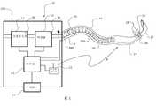
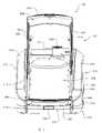
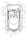
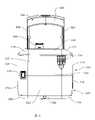
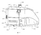
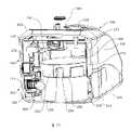
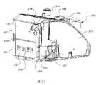
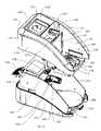
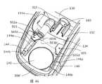
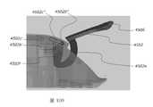
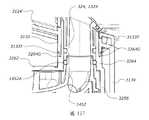
因此,根據在此揭露的實施方式中的至少一個的某些特徵、方面及優點,揭露了用於遞送氣流之設備,該設備包括:殼體,該殼體具有:用於電機和/或感測器模組的凹陷,用於氣流的出口端口,以及用於氣流的可移除彎管;以及增濕器,該增濕器具有:加熱器,腔室底座,該腔室底座用於接收液體腔室,以及桿件和/或棘爪,該桿件和/或棘爪用於輔助將該液體腔室插入和/或保持在該腔室底座中和/或從中移除。Accordingly, in accordance with certain features, aspects and advantages of at least one of the embodiments disclosed herein, an apparatus for delivering airflow is disclosed, the apparatus comprising: a housing having: a motor and/or sensor for a recess of the detector module, an outlet port for air flow, and a removable elbow for air flow; and a humidifier having: a heater, a chamber base for receiving A liquid chamber, and rods and/or detents for assisting in the insertion and/or retention of the liquid chamber in and/or removal from the chamber seat.
在一些構型中,該設備包括用於接收在該腔室底座中的液體腔室,該液體腔室包括可連接到該出口端口上的入口端口以及可連接到該可移除彎管上的出口端口。在一些構型中,該等端口中的至少一個包括一個或多個撓性指桿,該一個或多個撓性指桿被構造成提供該端口與其可連接到的端口之間強制接合。In some configurations, the device includes a liquid chamber for receipt in the chamber base, the liquid chamber including an inlet port connectable to the outlet port and a port connectable to the removable elbow egress port. In some configurations, at least one of the ports includes one or more flexible fingers configured to provide forcing between the port and a port to which it can be connectedengage.
在一些構型中,該設備包括使用者介面。In some configurations, the device includes a user interface.
在一些構型中,該腔室底座形成於該殼體之中。In some configurations, the chamber base is formed in the housing.
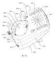
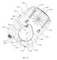
另外地,根據在此揭露的實施方式中的至少一個的某些特徵、方面及優點,揭露了用於遞送氣流之設備,該設備包括:具有凹陷的殼體,以及用於氣流的出口端口,其中,除了從該凹陷到該殼體的該出口端口的氣流通道之外,該凹陷係由基本上連續的、氣體不可滲透的且未中斷的至少一個壁限定。Additionally, in accordance with certain features, aspects, and advantages of at least one of the embodiments disclosed herein, an apparatus for delivering airflow is disclosed, the apparatus comprising: a housing having a recess, and an outlet port for airflow, wherein the recess is defined by at least one wall that is substantially continuous, gas impermeable and uninterrupted, except for the passage of gas flow from the recess to the outlet port of the housing.
在一些構型中,該凹陷包括位於該殼體的外壁中的凹陷開口,其中該凹陷從該凹陷開口延伸到該殼體之中。在一些構型中,該凹陷開口位於該殼體的底部之中。可替代地,該凹陷開口可以位於該殼體的不同部分中,諸如該殼體的側部、前部或頂部。在一些構型中,該凹陷開口位於該殼體的頂部之中。In some configurations, the recess includes a recess opening in the outer wall of the housing, wherein the recess extends from the recess opening into the housing. In some configurations, the recessed opening is located in the bottom of the housing. Alternatively, the recessed opening may be located in a different part of the housing, such as the side, front or top of the housing. In some configurations, the recessed opening is located in the top of the housing.
在一些構型中,該凹陷用於接收電機和/或感測器模組。In some configurations, the recess is used to receive a motor and/or sensor module.
在一些構型中,該設備包括定位在該凹陷中的電機和/或感測器模組。In some configurations, the device includes a motor and/or sensor module positioned in the recess.
在一些構型中,該設備被構造成使得氣體經由該凹陷進入該殼體並且經由該出口端口離開該殼體。在一些構型中,該氣體由從它們的進口到該殼體的氣體通道遞送到該出口端口。在一些構型中,該氣體通道係由該電機和/或感測器模組提供。In some configurations, the apparatus is configured such that gas enters the housing via the recess and exits the housing via the outlet port. In some configurations, the gas is delivered to the outlet port by gas passages from their inlet to the housing. In some configurations, the gas channel is provided by the motor and/or sensor module.
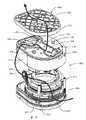
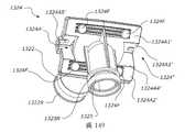
在一些構型中,該電機和/或感測器模組包括組裝在一起以便形成子組件殼體的基部、感測層以及覆蓋層。在一些構型中,該子組件殼體具有與該凹陷的形狀互補的形狀。In some configurations, the motor and/or sensor module includes a base, a sensing layer, and a cover layer that are assembled together to form a subassembly housing. In some configurations, the subassembly housing has a shape complementary to the shape of the recess.
在一些構型中,該電機和/或感測器模組包括具有葉輪的電機,該電機被安排成將氣體遞送到該殼體的該出口端口。在一些構型中,該電機被定位在該子組件的該基部上。In some configurations, the motor and/or sensor module includes a motor with an impeller arranged to deliver gas to the outlet port of the housing. In some configurations, the motor is positioned on the base of the subassembly.
在一些構型中,該基部被構造成當該子組件被定位在該凹陷中時封閉該凹陷開口。In some configurations, the base is configured to close the recess opening when the subassembly is positioned in the recess.
在一些構型中,該子組件係由緊固件、夾具或快速釋放安排維持在該凹陷中的適當位置之中。In some configurations, the subassembly is held in place in the recess by fasteners, clamps or quick release arrangements.
在一些構型中,該感測層包括具有一個或多個感測器的氣流路徑。在一些構型中,該氣流路徑被安排成將氣體遞送到該殼體的該出口端口。在一些構型中,該氣體係或包含氧氣。在一些構型中,該氣體包含氧氣和周圍空氣的共混物。In some configurations, the sensing layer includes an airflow path with one or more sensors. In some configurations, the gas flow path is arranged to deliver gas to the outlet port of the housing. In some configurations, the gas system may contain oxygen. In some configurations, the gas comprises a blend of oxygen and ambient air.
在一些構型中,該氣流路徑包括細長氣流部分。In some configurations, the airflow path includes an elongated airflow portion.
在一些構型中,該氣流路徑具有切向進口部分,該切向進口部分被定位在該細長氣流部分的進口端處或與該進口端鄰近。In some configurations, the airflow path has a tangential inlet portion positioned at or adjacent an inlet end of the elongated airflow portion.
在一些構型中,該電機和/或感測器模組包括具有蜿蜒安排的氣流路徑。In some configurations, the motor and/or sensor module includes an airflow path having a serpentine arrangement.
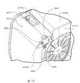
在一些構型中,該殼體包括電氣部件和/或電子部件,並且其中該凹陷被構造成使該等電氣部件和/或電子部件與穿過或來自該電機和/或感測器模組的氣流隔離。在一些構型中,該氣流通道係由氣流通道管提供,並且其中該氣流通道管延伸穿過與該殼體的一部分整體形成的外管。In some configurations, the housing includes electrical and/or electronic components, and wherein the recess is configured to connect the electrical and/or electronic components to pass through or from the motor and/or sensor module airflow isolation. In some configurations, the airflow channel is provided by an airflow channel tube, and wherein the airflow channel tube extends through an outer tube integrally formed with a portion of the housing.
在一些構型中,該設備被構造成使得如果該電機和/或感測器模組的該等密封件中的任一個中出現洩漏,氧氣將洩漏到大氣而不是該等電氣部件和/或電子部件。In some configurations, the apparatus is configured such that if a leak occurs in any of the seals of the motor and/or sensor module, oxygen will leak to the atmosphere instead of the electrical components and/or electronic components.
在一些構型中,密封件設置在該電機和/或感測器模組的部分與該凹陷的壁之間,以便將該模組密封到該殼體上。在一些構型中,該密封件包括軟密封件,諸如O形環。在一些構型中,該密封件設置在該電機和/或感測器模組的基部與該凹陷的該壁之間。在一些構型中,該基部支撐具有葉輪的電機。In some configurations, a seal is disposed between the portion of the motor and/or sensor module and the wall of the recess to seal the module to the housing. In some configurations, the seal includes a soft seal, such as an O-ring. In some configurations, the seal is disposed between the base of the motor and/or sensor module and the wall of the recess. In some configurations, the base supports a motor with an impeller.
在一些構型中,該電機和/或感測器模組係從該凹陷可移除的。在一些替代構型中,該電機和/或感測器模組可以不是從該凹陷可移除的。In some configurations, the motor and/or sensor module is removable from the recess. In some alternative configurations, the motor and/or sensor module may not be removable from the recess.
在一些構型中,該電機和/或感測器模組包括具有葉輪和氣體出口端口的電機,並且該氣體出口端口由撓性套箍聯接到鄰近部件的入口端口上。在一些構型中,該電機和/或感測器模組包括被構造成支撐該套箍的套箍支撐構件。在一些構型中,該套箍支撐構件包括豎立套箍支撐構件,該豎立套箍支撐構件具有向內凹的形狀並且被構造成接收並支撐該套箍之周邊。在一些構型中,該套箍的氣體出口端口端包括停靠在該套箍支撐構件的上端上的擴大的直徑。In some configurations, the motor and/or sensor module includes a motor having an impeller and a gas outlet port, and the gas outlet port is coupled by a flexible ferrule to an inlet port of an adjacent component. In some configurations, the motor and/or sensor module includes a ferrule support member configured to support the ferrule. In some configurations, the ferrule support member includes an upstanding ferrule support member having an inwardly concave shape and configured to receive and support a perimeter of the ferrule. In some configurations, the gas outlet port end of the ferrule includes an enlarged diameter resting on the upper end of the ferrule support member.
在一些構型中,是氧氣或包含氧氣的氣體流動穿過該氣流通道和/或該出口端口。在一些構型中,該氣體係與該殼體中的電氣部件和/或電子部件隔離的。在一些構型中,該氣體包含氧氣和周圍空氣的共混物。In some configurations, it is the flow of oxygen or a gas comprising oxygen through the gas flow channel and/or the outlet port. In some configurations, the gas system is isolated from electrical and/or electronic components in the housing. In some configurations, the gas comprises a blend of oxygen and ambient air.
另外地,根據在此揭露的實施方式中的至少一個的某些特徵、方面及優點,揭露了供在該設備中使用的電機和/或感測器模組,該電機和/或感測器模組具有以上列舉的特徵。Additionally, in accordance with certain features, aspects and advantages of at least one of the embodiments disclosed herein, a motor and/or sensor module for use in the apparatus is disclosed, the motor and/or sensor The modules have the features listed above.
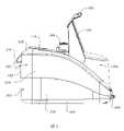
另外地,根據在此揭露的實施方式中的至少一個的某些特徵、方面及優點,揭露了用於遞送氣流之設備,該設備包括:增濕器,該增濕器具有:加熱器,腔室底座,該腔室底座用於接收液體腔室,以及桿件,該桿件用於輔助將該液體腔室插入和/或保持在該腔室底座中和/或從在該腔室底座中移除。Additionally, in accordance with certain features, aspects, and advantages of at least one of the embodiments disclosed herein, an apparatus for delivering airflow is disclosed, the apparatus comprising: a humidifier having: a heater, a chamber a chamber base for receiving the liquid chamber, andA rod for assisting in the insertion and/or retention of the liquid chamber in and/or removal from the chamber base.
在一些構型中,該桿件被構造用於輔助該液體腔室的插入、保持、移除中的一項。在一些構型中,該桿件被構造用於輔助該液體腔室的插入、保持、移除中的兩項。在一些構型中,該桿件被構造用於輔助該液體腔室的插入、保持、移除這所有三項。In some configurations, the rod is configured to assist in one of insertion, retention, and removal of the liquid chamber. In some configurations, the rod is configured to assist in both of insertion, retention, and removal of the liquid chamber. In some configurations, the rod is configured to assist in all three of insertion, retention, and removal of the liquid chamber.
不同質性可以被構造用於輔助將該液體腔室插入、保持在該腔室底座中、或從在該腔室底座中移除中的一項、兩項或全部。Inhomogeneity may be configured to assist in one, both, or both of insertion of the liquid chamber, retention in the chamber base, or removal from the chamber base.
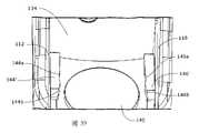
在一些構型中,該腔室底座包括相對的引導特徵以便輔助將該液體腔室引導到該腔室底座中的適當位置之中。在一些構型中,該等相對的引導特徵包括相對的導軌,該等導軌被安排成與液體腔室上的向外定向的環形凸緣相互作用。In some configurations, the chamber base includes opposing guiding features to assist in guiding the liquid chamber into position in the chamber base. In some configurations, the opposing guide features include opposing rails arranged to interact with outwardly oriented annular flanges on the liquid chamber.
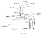
在一些構型中,該桿件被構造成使得當該桿件處於第一位置中時,液體腔室可以被插入到該腔室底座中或從在該腔室底座中移除;並且被構造成使得當該桿件處於第二位置中時,該桿件抑制或阻止將液體腔室從該腔室底座移除。In some configurations, the lever is configured such that when the lever is in the first position, the liquid chamber can be inserted into or removed from the chamber base; and is configured Such that when the lever is in the second position, the lever inhibits or prevents removal of the liquid chamber from the chamber base.
在一些構型中,該桿件包括至少一個液體腔室接合特徵,以便當該桿件朝向該第二位置被移動時,與該液體腔室的部分接合並且驅動該液體腔室來接合在該腔室底座之中。在一些構型中,該設備包括兩個液體腔室接合特徵,其中該等液體腔室接合特徵包括向內定向的突起。In some configurations, the lever includes at least one liquid chamber engagement feature to engage with a portion of the liquid chamber and actuate the liquid chamber to engage in the second position when the lever is moved toward the second position in the base of the chamber. In some configurations, the device includes two liquid chamber engaging features, wherein the liquid chamber engaging features include inwardly directed protrusions.
在一些構型中,該設備包括強制接合特徵以便將該手柄保持在該第二位置之中。In some configurations, the device includes a positive engagement feature to maintain the handle in the second position.
在一些構型中,該桿件包括手柄部分以便使得當該桿件處於提起位置中時,該設備能夠被搬運。In some configurations, the lever includes a handle portion such that when the lever is raisedWhen in position, the device can be transported.
在一些構型中,該桿件被樞轉地連接到該設備的殼體上。在一些構型中,該桿件的僅一側被樞轉地連接到該殼體上。In some configurations, the lever is pivotally connected to the housing of the device. In some configurations, only one side of the lever is pivotally connected to the housing.
在一些構型中,該桿件被樞轉地且平移地連接到該設備的該殼體上。在一些構型中,該設備包括桿件保持器,該桿件保持器被固定到該殼體的部分上,其中該桿件保持器和該殼體的該部分一起提供該桿件相對於該殼體的樞轉且平移的移動。In some configurations, the lever is pivotally and translationally connected to the housing of the device. In some configurations, the apparatus includes a rod holder secured to a portion of the housing, wherein the rod holder and the portion of the housing together provide the rod relative to the housing Pivoting and translational movement of the housing.
在一些構型中,該桿件被構造成相對於該殼體以變化的移動半徑移動。In some configurations, the rod is configured to move with a varying radius of movement relative to the housing.
在一些構型中,該桿件包括被構造成沿著第一樞軸腔移動的第一樞軸,並且該桿件包括被構造成沿著第二樞軸腔移動的第二樞軸。In some configurations, the lever includes a first pivot configured to move along the first pivot cavity, and the lever includes a second pivot configured to move along the second pivot cavity.
在一些構型中,該第一樞軸腔在相對於該殼體的基本上上下取向上取向。在一些構型中,該第一樞軸腔係基本上筆直的。In some configurations, the first pivot cavity is oriented in a substantially up-down orientation relative to the housing. In some configurations, the first pivot cavity is substantially straight.
在一些構型中,該第二樞軸腔在該設備的基本上前後方向上取向。在一些構型中,該第二樞軸腔係弧形的。In some configurations, the second pivot cavity is oriented in a substantially front-to-rear direction of the device. In some configurations, the second pivot cavity is arcuate.
在一些構型中,該設備包括接合特徵,以便將該第二樞軸保持在該第二樞軸腔的後端處或與該後端鄰近,從而保持該桿件處於提起位置之中。In some configurations, the apparatus includes an engagement feature to retain the second pivot at or adjacent the rear end of the second pivot cavity to retain the lever in the raised position.
在一些構型中,該桿件被構造用於輔助將該液體腔室從該腔室底座移除。In some configurations, the rod is configured to assist in removing the liquid chamber from the chamber base.
另外地,根據在此揭露的實施方式中的至少一個的某些特徵、方面及優點,揭露了用於遞送氣流之設備,該設備包括:增濕器,該增濕器具有:加熱器,以及用於液體腔室的腔室底座;其中該設備包括至少一個棘爪,該至少一個棘爪用於輔助該液體腔室將插入和/或保持在該腔室底座之中。Additionally, in accordance with certain features, aspects, and advantages of at least one of the embodiments disclosed herein, an apparatus for delivering an airflow is disclosed, the apparatus comprising: a humidifier having: a heater, andA chamber seat for a liquid chamber; wherein the apparatus includes at least one pawl for assisting in the insertion and/or retention of the liquid chamber within the chamber seat.
在一些構型中,該設備包括僅一個棘爪。在一些構型中,該設備包括兩個或更多個棘爪。In some configurations, the device includes only one pawl. In some configurations, the device includes two or more pawls.
在一些構型中,該腔室底座包括相對的引導特徵以便輔助將該液體腔室引導到該腔室底座中的適當位置之中。In some configurations, the chamber base includes opposing guiding features to assist in guiding the liquid chamber into position in the chamber base.
在一些構型中,棘爪鄰近該等引導特徵中的一個設置。在一些構型中,兩個棘爪鄰近對應引導特徵設置。In some configurations, the pawl is positioned adjacent one of the guide features. In some configurations, two pawls are disposed adjacent to corresponding guide features.
在一些構型中,棘爪設置該等引導特徵中的一個上。在一些構型中,兩個棘爪設置在對應引導特徵上。In some configurations, the pawl is disposed on one of the guide features. In some configurations, two pawls are provided on corresponding guide features.
在一些構型中,該引導特徵包括相對的導軌,該等導軌被安排成與液體腔室上的向外定向的環形凸緣相互作用,並且其中棘爪包括位於該等導軌中的一者或兩者中的擴大的凹陷。在一些構型中,該等導軌中的一者或兩者包括向內定向的凸脊。在一些構型中,向內定向的凸脊具有足以在該液體腔室被插入該等導軌之間和/或從該等導軌移除時變形的彈力。In some configurations, the guide feature includes opposing rails arranged to interact with outwardly directed annular flanges on the liquid chamber, and wherein the pawl includes on one of the rails or Enlarged depressions in both. In some configurations, one or both of the rails include inwardly oriented ridges. In some configurations, the inwardly directed ridges have sufficient spring force to deform when the liquid chamber is inserted between and/or removed from the rails.
在一些構型中,該等引導特徵中的一者或兩者包括突起,其中該液體腔室包括凹陷以便接收突起。In some configurations, one or both of the guide features include protrusions, wherein the liquid chamber includes recesses to receive the protrusions.
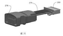
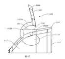
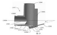
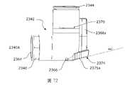
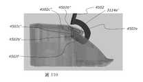
另外地,根據在此揭露的實施方式中的至少一個的某些特徵、方面及優點,揭露了用於遞送氣流之設備,該設備包括:殼體,以及可移除氣流管,該可移除氣流管用於氣流的限定氣流通道,以及可移除保持蓋,該可移除保持蓋被構造成使得在該可移除保持蓋從該殼體移除的情況下,該可移除氣流管可以從該殼體移除,並且在該可移除保持蓋連接到該殼體上的情況下,該可移除氣流管不能從該殼體移除。Additionally, in accordance with certain features, aspects, and advantages of at least one of the embodiments disclosed herein, an apparatus for delivering airflow is disclosed, the apparatus comprising: a housing, and a removable airflow duct, the removable an airflow duct for defining airflow passages for airflow, and a removable retention cover configured so that when the removable retention cover is removed from the housingWith removal, the removable airflow tube can be removed from the housing, and with the removable retention cover attached to the housing, the removable airflow tube cannot be removed from the housing remove.
在一些構型中,該殼體包括用於接收該可移除氣流管的保持器,並且其中該可移除保持蓋被構造成使得在該可移除保持蓋從該保持器移除的情況下,該可移除氣流管可以從該殼體移除,並且在該可移除保持蓋連接到該殼體上的情況下,該可移除氣流管不能從該保持器移除。In some configurations, the housing includes a retainer for receiving the removable airflow tube, and wherein the removable retention cover is configured such that when the removable retention cover is removed from the retainer In this case, the removable airflow tube is removable from the housing and cannot be removed from the holder with the removable retention cover attached to the housing.
在一些構型中,需要兩個離散的動作來將該可移除氣流管從該保持器移除。在一些構型中,該可移除保持蓋係藉由在第一方向移動該可移除蓋件而從該殼體可移除的,其中該可移除氣流管係藉由在第二方向上移動該可移除氣流管而從該保持器可移除的,對於該移動的至少部分,該第二方向基本上橫向於該第一方向。在一些構型中,該可移除氣流管包括氣體端口,該氣體端口用於與液體腔室上的出口端口聯接,該液體腔室被安排成被接收在該殼體的腔室底座中,並且該第二方向對應於將該液體腔室從該腔室底座移除的方向。In some configurations, two discrete actions are required to remove the removable gas flow tube from the holder. In some configurations, the removable retention cover is removable from the housing by moving the removable cover in a first direction, wherein the removable airflow duct is removed from the housing by moving the removable cover in a second direction Moving the removable airflow tube up to be removable from the holder, for at least part of the movement, the second direction is substantially transverse to the first direction. In some configurations, the removable gas flow tube includes a gas port for coupling with an outlet port on a liquid chamber arranged to be received in a chamber seat of the housing, And the second direction corresponds to the direction in which the liquid chamber is removed from the chamber base.
在一些構型中,該可移除氣流管包括電連接器,該電連接器被聯接到該可移除氣流管中的一個或多個感測器和/或電源連接器上。在一些構型中,該電連接器包括從該氣流管的一部分凸出的陽連接器部分,其中該殼體包括互補陰連接器,該互補陰連接器用於在該氣流管被連接到該殼體上時接收該陽連接器。在一些構型中,該殼體包括陽連接器部分,並且該可移除氣流管包括互補陰連接器,該互補陰連接器用於在該氣流管被連接到該殼體上時接收該陽連接器。In some configurations, the removable airflow tube includes an electrical connector coupled to one or more sensors and/or power connectors in the removable airflow tube. In some configurations, the electrical connector includes a male connector portion protruding from a portion of the airflow tube, wherein the housing includes a complementary female connector for connecting the airflow tube to the housing receive the male connector when on the body. In some configurations, the housing includes a male connector portion and the removable airflow tube includes a complementary female connector for receiving the male connection when the airflow tube is connected to the housing device.
在一些構型中,該可移除氣流管包括具有軸線的端口,並且該電連接器被取向成處於相對於該軸線在約-15度與約+30度之間、在一些構型中相對於該軸線在約0度與約+30度之間、在一些構型中相對於該軸線在約0度與約+15度之間的角度,並且在一些構型中處於相對於該軸線為約+15度的角度。在一些構型中,該電連接器被安排成在使用中被取向成處於非水平角度。在一些構型中,該電連接器被取向成處於相對於該軸線非平行且非共軸的角度。在一些構型中,該電連接器被取向成處於相對於該軸線在約-5度與約-15度之間、或相對於該軸線在約+5度與約+30度之間的角度。在一些構型中,該電連接器被取向處於相對於該軸線在約+5度與約+30度之間、在一些構型中相對於該軸線在約+5度與約+15度之間的角度,並且在一些構型中處於相對於該軸線為約+15度的角度。In some configurations, the removable airflow tube includes a port having an axis, and the electrical connector is oriented between about -15 degrees and about +30 degrees relative to the axis, opposite in some configurations between about 0 degrees and about +30 degrees relative to the axis, and in some configurations between about 0 degrees and about +15 degrees relative to the axisdegrees, and in some configurations at an angle of about +15 degrees relative to this axis. In some configurations, the electrical connector is arranged to be oriented in use at a non-horizontal angle. In some configurations, the electrical connector is oriented at a non-parallel and non-coaxial angle relative to the axis. In some configurations, the electrical connector is oriented at an angle of between about -5 degrees and about -15 degrees relative to the axis, or between about +5 degrees and about +30 degrees relative to the axis . In some configurations, the electrical connector is oriented between about +5 degrees and about +30 degrees relative to the axis, in some configurations between about +5 degrees and about +15 degrees relative to the axis angle between, and in some configurations at an angle of about +15 degrees relative to this axis.
在一些構型中,該可移除氣流管的該電連接器被聯接到一個或多個溫度感測器上,以便確定流動穿過該氣流管的氣體的溫度。In some configurations, the electrical connector of the removable gas flow tube is coupled to one or more temperature sensors to determine the temperature of gas flowing through the gas flow tube.
在一些構型中,該可移除氣流管的該電連接器被聯接到該可移除氣流管中的電源連接器上,該電源連接器用於聯接到患者呼吸導管的加熱線上並向其供電,該可移除氣流管被構造成當患者呼吸導管被連接到該可移除氣流管上時,在單個動作中提供到該患者導管的氣動和電氣連接。In some configurations, the electrical connector of the removable airflow tube is coupled to a power connector in the removable airflow tube for coupling to and powering a heating wire of a patient breathing catheter , the removable airflow tube is configured to provide pneumatic and electrical connections to the patient conduit in a single action when the patient breathing conduit is connected to the removable airflow tube.
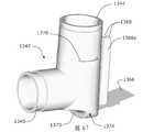
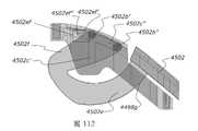
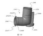
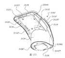
在一些構型中,該可移除氣流管包括可移除彎管。In some configurations, the removable airflow tube includes a removable elbow.
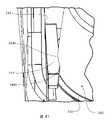
另外地,根據在此揭露的實施方式中的至少一個的某些特徵、方面及優點,揭露了用於遞送氣流之設備,該設備包括:殼體,該殼體包括上底盤和下底盤,氣流通道,該氣流通道在該殼體中被限定在該上底盤與該下底盤之間,位於該殼體中的電氣部件,以及位於該殼體中的連續的、未中斷的壁,該壁被適配成使該電氣部件與該氣流通道氣動隔離。Additionally, in accordance with certain features, aspects, and advantages of at least one of the embodiments disclosed herein, an apparatus for delivering airflow is disclosed, the apparatus comprising: a housing including an upper chassis and a lower chassis, the airflow a channel defined in the housing between the upper chassis and the lower chassis, electrical components located in the housing, and a continuous, uninterrupted wall located in the housing, the wall being Adapted to pneumatically isolate the electrical component from the airflow channel.
在一些構型中,是氧氣或包含氧氣的氣體流動穿過該氣流通道。在一些構型中,該氣體係與該電氣部件隔離的。在一些構型中,該氣體包含氧氣和周圍空氣的共混物。In some configurations, oxygen or a gas containing oxygen flows through the gas flow channel. In some configurations, the gas system is isolated from the electrical components. In some configurations, the gas contains oxygenand ambient air.
在一些構型中,該設備包括具有葉輪的電機以便將氣體遞送穿過該氣流通道,其中該電機係與該電氣部件氣動隔離的。在一些構型中,該壁,單獨地抑或與一個或多個另外的連續的未中斷的壁相結合,限定與該電氣部件氣動隔離的凹陷,其中該電機被定位在該凹陷之中。In some configurations, the apparatus includes a motor having an impeller for delivering gas through the gas flow channel, wherein the motor is pneumatically isolated from the electrical components. In some configurations, the wall, alone or in combination with one or more additional continuous uninterrupted walls, defines a recess that is pneumatically isolated from the electrical component in which the motor is positioned.
在一些構型中,該電機係從該凹陷可移除的。In some configurations, the motor is removable from the recess.
在一些構型中,在該電機葉輪的上游壓力較低並且在該電機葉輪的下游壓力較高,並且該電機包括被定位在該電機葉輪的上游、位於該低壓力區域中的電氣連接。In some configurations, the pressure is lower upstream of the motor wheel and higher downstream of the motor wheel, and the motor includes an electrical connection positioned upstream of the motor wheel in the low pressure region.
在一些構型中,該電氣部件包括印刷電路板。In some configurations, the electrical component includes a printed circuit board.
另外地,根據在此揭露的實施方式中的至少一個的某些特徵、方面及優點,揭露了用於遞送氣流之設備,該設備包括:殼體和桿件,其中該桿件的僅一側被可動地連接到該殼體上。Additionally, in accordance with certain features, aspects, and advantages of at least one of the embodiments disclosed herein, an apparatus for delivering airflow is disclosed, the apparatus comprising: a housing and a rod, wherein only one side of the rod is is movably connected to the housing.
在一些構型中,該設備包括加熱器以及用於接收液體腔室的腔室底座。In some configurations, the apparatus includes a heater and a chamber base for receiving the liquid chamber.
在一些構型中,當該桿件處於提起位置中時,液體管可以被饋送穿過位於該桿件與該殼體之間的空間。In some configurations, a liquid tube may be fed through the space between the rod and the housing when the rod is in the raised position.
在一些構型中,該桿件的所述一側被樞轉地連接到該殼體上。In some configurations, the side of the lever is pivotally connected to the housing.
在一些構型中,當該桿件處於閉合位置中時,該桿件包圍該腔室底座的一部分。In some configurations, the lever surrounds a portion of the chamber base when the lever is in the closed position.
在一些構型中,該桿件的所述一側被樞轉地且平移地連接到該殼體上。In some configurations, the one side of the lever is pivotally and translationally connected to the housing.
在一些構型中,當該桿件處於閉合位置中時,該桿件的一部分充分地凸出到該腔室底座的底板上方,從而阻止液體腔室從該腔室底座被移除。In some configurations, when the lever is in the closed position, a portion of the lever fillsPartially protrudes above the bottom plate of the chamber base, preventing the liquid chamber from being removed from the chamber base.
在一些構型中,該桿件的所述一側被樞轉地且平移地連接到該殼體上。In some configurations, the one side of the lever is pivotally and translationally connected to the housing.
在一些構型中,該設備包括桿件保持器,該桿件保持器被固定到該殼體的部分上,其中該桿件保持器和該殼體的該部分一起提供該桿件相對於該殼體的樞轉且平移的移動。In some configurations, the apparatus includes a rod holder secured to a portion of the housing, wherein the rod holder and the portion of the housing together provide the rod relative to the housing Pivoting and translational movement of the housing.
在一些構型中,該桿件被構造成相對於該殼體以變化的移動半徑移動。In some configurations, the rod is configured to move with a varying radius of movement relative to the housing.
在一些構型中,該桿件包括被構造成沿著第一樞軸腔移動的第一樞軸,並且其中該桿件包括被構造成沿著第二樞軸腔移動的第二樞軸。In some configurations, the lever includes a first pivot configured to move along the first pivot cavity, and wherein the lever includes a second pivot configured to move along the second pivot cavity.
在一些構型中,該第一樞軸腔在相對於該殼體的基本上上下取向上取向。在一些構型中,該第一樞軸腔係基本上筆直的。In some configurations, the first pivot cavity is oriented in a substantially up-down orientation relative to the housing. In some configurations, the first pivot cavity is substantially straight.
在一些構型中,該第二樞軸腔在該設備的基本上前後方向上取向。在一些構型中,該第二樞軸腔係弧形的。In some configurations, the second pivot cavity is oriented in a substantially front-to-rear direction of the device. In some configurations, the second pivot cavity is arcuate.
在一些構型中,該設備包括接合特徵,以便將該第二樞軸保持在該第二樞軸腔的後端處或與該後端鄰近,從而保持該桿件處於提起位置之中。In some configurations, the apparatus includes an engagement feature to retain the second pivot at or adjacent the rear end of the second pivot cavity to retain the lever in the raised position.
在一些構型中,該桿件包括位於該桿件的所述一側上的臂,其中該臂被樞轉地、或樞轉地且平移地連接到該殼體上。在一些構型中,該桿件包括連接到該臂上的橫樑。In some configurations, the lever includes an arm on the side of the lever, wherein the arm is pivotally, or pivotally and translationally connected to the housing. In some configurations, the rod includes a beam attached to the arm.
在一些構型中,當該桿件處於提起位置中時,在該桿件的與該臂相反的一側上,在該殼體與該橫樑之間存在空間。In some configurations, there is a space between the housing and the beam on the side of the rod opposite the arm when the rod is in the raised position.
在一些構型中,該桿件的終端端部被安排成當該桿件處於完全提起位置中時,總體上被定位在該設備的質心上方。In some configurations, the terminal end of the rod is arranged to be positioned generally above the center of mass of the device when the rod is in the fully raised position.
在一些構型中,該桿件包括用於將液體管引導到液體腔室的一個或多個特徵。In some configurations, the rod includes one or more features for directing the liquid tube to the liquid chamber.
在一些構型中,該桿件被構造用於輔助將該液體腔室插入和/或保持在該腔室底座中和/或從在該腔室底座中移除。In some configurations, the rod is configured to assist in inserting and/or retaining and/or removing the liquid chamber in the chamber base.
在一些構型中,該桿件係氣體注塑模製的。In some configurations, the rod is gas injection molded.
在一些構型中,該桿件包括外部密封件。In some configurations, the rod includes an outer seal.
在一些構型中,在該桿件從完全降低位置到完全提起位置的整個移動過程中,該桿件的面抵靠在該殼體的面上。In some configurations, the face of the rod rests against the face of the housing throughout movement of the rod from the fully lowered position to the fully raised position.
在一些構型中,該桿件和/或殼體包括一個或多個磁體以便將該桿件保持在完全降低位置和/或完全提起位置之中。In some configurations, the rod and/or housing includes one or more magnets to maintain the rod in the fully lowered and/or fully raised position.
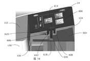
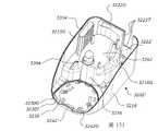
另外地,根據在此揭露的實施方式中的至少一個的某些特徵、方面及優點,揭露了用於遞送氣流之設備,該設備包括:殼體,該殼體具有位於該殼體的外壁中的凹陷,以及連接器安排,該連接器安排被定位在該凹陷中,其中該連接器安排包括一個或多個端口,並且其中該一個或多個端口處於相對於豎直軸線在0度與90度之間的非水平且非豎直的角度。Additionally, in accordance with certain features, aspects, and advantages of at least one of the embodiments disclosed herein, an apparatus for delivering an airflow is disclosed, the apparatus comprising: a housing having a device located in an outer wall of the housing the recess, and a connector arrangement in which the connector arrangement is positioned, wherein the connector arrangement includes one or more ports, and wherein the one or more ports are at 0 degrees and 90 degrees relative to the vertical axis A non-horizontal and non-vertical angle between degrees.
也就是說,該一個或多個端口至少部分地面向下,這樣使得插頭到連接器中的插入角度係至少部分地向上。That is, the one or more ports are at least partially facing downwards such that the angle of insertion of the plug into the connector is at least partially upwards.
在一些構型中,該一個或多個端口處於相對於該豎直軸線在約5度與約30度之間的角度。在一些構型中,該一個或多個端口處於相對於該豎直軸線在約10度與約20度之間的角度。在一些構型中,該一個或多個端口處於相對於該豎直軸線為約15度的角度。In some configurations, the one or more ports are at an angle of between about 5 degrees and about 30 degrees relative to the vertical axis. In some configurations, the one or more ports are at an angle of between about 10 degrees and about 20 degrees relative to the vertical axis. In some configurations, the one or more ports are at an angle of about 15 degrees relative to the vertical axis.
在一些構型中,該等凹陷的壁係相對於該豎直方向以該一個或多個端口的插入角度傾斜的。In some configurations, the walls of the recesses are aligned with the one or moreThe insertion angle of each port is inclined.
在一些構型中,一個或多個端口包括通訊連接端口。在一些構型中,一個或多個端口包括USB端口。In some configurations, the one or more ports include communication connection ports. In some configurations, the one or more ports include USB ports.
在一些構型中,唇緣設置在這個或每個端口上以便降低水滲入到端口中的可能性。In some configurations, a lip is provided on the or each port to reduce the likelihood of water seeping into the port.
在一些構型中,該設備包括沿著該凹陷的上邊緣的尖銳邊緣或液體偏轉器,以便促進液體從該尖銳邊緣/液體偏轉器滴落而不是流進該凹陷之中。In some configurations, the device includes a sharp edge or liquid deflector along the upper edge of the recess to facilitate liquid dripping from the sharp edge/liquid deflector rather than flowing into the recess.
另外地,根據在此揭露的實施方式中的至少一個的某些特徵、方面及優點,揭露了用於遞送氣流之設備,該設備包括:殼體;以及用於氣流的可移除氣流管,其中該可移除氣流管包括具有軸線的端口以及電連接器,該電連接器用於在該氣流管被連接到該殼體上時聯接到互補連接器上,其中該電連接器被取向成處於相對於該軸線在約-15度與約+30度之間的角度。Additionally, in accordance with certain features, aspects, and advantages of at least one of the embodiments disclosed herein, an apparatus for delivering airflow is disclosed, the apparatus comprising: a housing; and a removable airflow tube for airflow, wherein the removable airflow tube includes a port having an axis and an electrical connector for coupling to a complementary connector when the airflow tube is connected to the housing, wherein the electrical connector is oriented in a An angle between about -15 degrees and about +30 degrees relative to the axis.
在一些構型中,該電連接器被取向處於相對於該軸線在約0度與約+30度之間、在一些構型中相對於該軸線在約0度與約+15度之間的角度,並且在一些構型中處於相對於該軸線為約+15度的角度。In some configurations, the electrical connector is oriented between about 0 degrees and about +30 degrees relative to the axis, in some configurations between about 0 degrees and about +15 degrees relative to the axis angle, and in some configurations at an angle of about +15 degrees relative to this axis.
在一些構型中,該電連接器被安排成在使用中被取向成處於非水平角度。In some configurations, the electrical connector is arranged to be oriented in use at a non-horizontal angle.
在一些構型中,該電連接器被取向成處於相對於該軸線非平行且非共軸的角度。在一些構型中,該電連接器被取向成處於相對於該軸線在約-5度與約-15度之間、或相對於該軸線在約+5度與約+30度之間的角度。在一些構型中,該電連接器被取向處於相對於該軸線在約+5度與約+30度之間、在一些構型中相對於該軸線在約+5度與約+15度之間的角度,並且在一些構型中處於相對於該軸線為約+15度的角度。In some configurations, the electrical connector is oriented at a non-parallel and non-coaxial angle relative to the axis. In some configurations, the electrical connector is oriented at an angle of between about -5 degrees and about -15 degrees relative to the axis, or between about +5 degrees and about +30 degrees relative to the axis . In some configurations, the electrical connector is oriented between about +5 degrees and about +30 degrees relative to the axis, in some configurationsis at an angle of between about +5 degrees and about +15 degrees relative to the axis in some configurations, and in some configurations is at an angle of about +15 degrees relative to the axis.
在一些構型中,該可移除氣流管包括可移除彎管。In some configurations, the removable airflow tube includes a removable elbow.
另外地,根據在此揭露的實施方式中的至少一個的某些特徵、方面及優點,揭露了用於遞送氣流之設備,該設備包括:殼體;以及用於氣流的可移除氣流管,其中該可移除氣流管包括電連接器,該電連接器用於在該氣流管被連接到該殼體上時聯接到互補連接器上,其中該可移除氣流管的本體被包覆模製到該電連接器上。Additionally, in accordance with certain features, aspects, and advantages of at least one of the embodiments disclosed herein, an apparatus for delivering airflow is disclosed, the apparatus comprising: a housing; and a removable airflow tube for airflow, wherein the removable airflow tube includes an electrical connector for coupling to a complementary connector when the airflow tube is connected to the housing, wherein the body of the removable airflow tube is overmolded to the electrical connector.
在一些構型中,該可移除氣流管包括被嵌入在該包覆模製氣流管本體的部分中的電源連接器。在一些構型中,該電源連接器包括向上凸出的插腳連接器,該插腳連接器用於聯接到患者呼吸導管中的加熱線上並向其供電。在一些構型中,該等插腳連接器基本上平行於該彎管的氣體出口端口的縱軸延伸。In some configurations, the removable airflow tube includes a power connector embedded in a portion of the overmolded airflow tube body. In some configurations, the power connector includes an upwardly projecting pin connector for coupling to and powering a heating wire in the patient breathing conduit. In some configurations, the pin connectors extend substantially parallel to the longitudinal axis of the gas outlet port of the elbow.
在一些構型中,該電連接器包括PCB電連接器。In some configurations, the electrical connector includes a PCB electrical connector.
在一些構型中,該可移除氣流管包括可移除彎管。In some configurations, the removable airflow tube includes a removable elbow.
另外地,根據在此揭露的實施方式中的至少一個的某些特徵、方面及優點,揭露了用於遞送氣流之設備,該設備包括:殼體;以及用於氣流的可移除氣流管,其中該可移除氣流管限定氣流通道並且包括內部凹池區域,該內部凹池區域與該氣流通道連通以便允許淤積液體。Additionally, in accordance with certain features, aspects, and advantages of at least one of the embodiments disclosed herein, an apparatus for delivering airflow is disclosed, the apparatus comprising: a housing; and a removable airflow tube for airflow, Wherein the removable gas flow tube defines a gas flow passage and includes an internal sump region in communication with the gas flow passage to allow pooling of liquid.
在一些構型中,該凹池區域係由該氣流通道中的擴大的區域提供。In some configurations, the recessed area is provided by an enlarged area in the airflow channel.
在一些構型中,該擴大的區域係該氣流通道的水平部分中的凹陷。In some configurations, the enlarged area is a depression in the horizontal portion of the airflow channel.
在一些構型中,該氣流管包括鄰近該凹池區域定位的溫度感測器,溫度感測器被安排成確定代表該氣流通道和/或氣體特性的溫度。In some configurations, the gas flow tube includes a temperature sensor positioned adjacent the well region,A temperature sensor is arranged to determine a temperature representative of the gas flow channel and/or gas characteristic.
在一些構型中,溫度感測器用於估計該氣體的濕度。In some configurations, a temperature sensor is used to estimate the humidity of the gas.
在一些構型中,該可移除氣流管包括可移除彎管。在一些構型中,該凹池區域設置在該彎管的第一端口和第二端口的交匯處。In some configurations, the removable airflow tube includes a removable elbow. In some configurations, the recessed area is provided at the intersection of the first port and the second port of the elbow.
另外地,根據在此揭露的實施方式中的至少一個的某些特徵、方面及優點,揭露了用於遞送氣流之設備,該設備包括:殼體;以及可移除氣流管,該可移除氣流管限定用於氣流的氣流通道,其中該可移除氣流管包括PCB電連接器,該PCB電連接器用於在該氣流管被連接到該殼體上時聯接到互補連接器上。Additionally, in accordance with certain features, aspects, and advantages of at least one of the embodiments disclosed herein, an apparatus for delivering airflow is disclosed, the apparatus comprising: a housing; and a removable airflow duct, the removable airflow The airflow duct defines an airflow channel for airflow, wherein the removable airflow duct includes a PCB electrical connector for coupling to a complementary connector when the airflow duct is connected to the housing.
在一些構型中,該可移除氣流管的第一端包括用於與液體腔室上的出口氣體端口聯接的氣體端口。在一些構型中,該可移除氣流管的第二端被構造用於連接到患者呼吸導管上。In some configurations, the first end of the removable gas flow tube includes a gas port for coupling with an outlet gas port on the liquid chamber. In some configurations, the second end of the removable airflow tube is configured for connection to a patient breathing conduit.
在一些構型中,該PCB電連接器部分在一個端部處包括多個連接器部分以用於與陰連接器中的互補導體接合。可替代地,在一些構型中,該可移除氣流管包括陰連接器,該陰連接器用於接收互補陽連接器。In some configurations, the PCB electrical connector portion includes a plurality of connector portions at one end for engagement with complementary conductors in the female connector. Alternatively, in some configurations, the removable airflow tube includes a female connector for receiving a complementary male connector.
在一些構型中,該可移除氣流管包括一個或多個電連接器,該一個或多個電連接器用於聯接到患者呼吸導管中的加熱線上並向其供電。在一些構型中,該電連接器與該PCB電連接器的連接器部分電通信。In some configurations, the removable airflow tube includes one or more electrical connectors for coupling to and powering a heating wire in the patient breathing conduit. In some configurations, the electrical connector is in electrical communication with a connector portion of the PCB electrical connector.
在一些構型中,該PCB電連接器包括表面安裝的溫度感測器。溫度感測器可以是例如熱電偶、數位溫度感測器、或熱敏電阻。在一些構型中,溫度感測器與該PCB電連接器的連接器部分電通信。在一些構型中,溫度感測器被嵌入在該氣流管的本體之中。In some configurations, the PCB electrical connector includes a surface mount temperature sensor. The temperature sensor may be, for example, a thermocouple, a digital temperature sensor, or a thermistor. In some configurations, the temperature sensor is in electrical communication with the connector portion of the PCB electrical connector. In some configurations, the temperature sensor is embedded in the body of the airflow tube.
在一些構型中,該可移除氣流管包括被構造成提供功能性的裝置,該功能性包括識別、校準功能性、或資訊捕獲中的一項或多項。在一些構型中,該裝置被構造成提供資訊,包括以下各項中的一項或多項:跟蹤資料、可移除氣流管已經使用了多久、首次使用可移除氣流管的時間、確定可移除氣流管年齡(例如,基於製造日期)、可移除氣流管已經被使用的次數、確定並記錄可移除氣流管的連接/斷開連接、確定消毒是否已經發生、可移除氣流管已經被消毒的次數、自最後一次消毒以來的使用時間、可移除氣流管應當被消毒的時間、功率電平、唯一ID、校準、可移除氣流管應當被更換的時間。在一些構型中,該可移除氣流管可以具有存儲在該裝置中的指定使用壽命,例如像從製造開始長達5年。在一些構型中,該可移除氣流管可以具有存儲在該裝置中的在該可移除氣流管應當被更換之前的指定最大消毒循環數目。例如,該最大消毒循環數目可以是持續指定周數的每週指定消毒循環數目。例如,對於具有為一年的最大使用壽命的可移除氣流管,最大消毒循環數目可以是52個循環;每週循環一次,持續一年。作為另一個實例,對於具有為5年的最大使用壽命的可移除氣流管,最大消毒循環數目可以是260個循環;每週循環一次,持續五年。In some configurations, the removable airflow tube includes a device configured to provide functionality including one or more of identification, calibration functionality, or information capture. In some configurations, the device is configured to provide information including one or more of the following: tracking data, how long the removable airflow tube has been used, the time the removable airflow tube was first used, the determination of available airflow Removal airflow tube age (eg, based on date of manufacture), number of times the removable airflow tube has been used, determining and recording removable airflow tube connection/disconnection, determining if sterilization has occurred, removable airflow tube Number of times it has been sterilized, time of use since last sterilization, when the removable airflow tube should be sterilized, power level, unique ID, calibration, when the removable airflow tube should be replaced. In some configurations, the removable airflow tube may have a specified useful life stored in the device, such as, for example, up to 5 years from manufacture. In some configurations, the removable airflow tube may have a specified maximum number of sterilization cycles stored in the device before the removable airflow tube should be replaced. For example, the maximum number of sterilization cycles may be a specified number of sterilization cycles per week for a specified number of weeks. For example, for a removable airflow tube with a maximum useful life of one year, the maximum number of sterilization cycles may be 52 cycles; one cycle per week for one year. As another example, for a removable airflow tube with a maximum useful life of 5 years, the maximum number of disinfection cycles may be 260 cycles; one cycle per week for five years.
在一些構型中,該裝置包括微處理器、記憶體、或具有集成記憶體的微處理器中的一個或多個。在一些構型中,該裝置係EEPROM。在一些構型中,該裝置可以是快閃記憶體記憶體或一些其他類型的記憶體。在一些構型中,該裝置可以被配置成存儲功能性資料,或可以被配置成經由該等連接器部分或經由適合的無線傳輸協議(例如像WI-FI、藍牙或GSM)向該設備的控制器傳達功能性資料。In some configurations, the device includes one or more of a microprocessor, memory, or a microprocessor with integrated memory. In some configurations, the device is an EEPROM. In some configurations, the device may be flash memory or some other type of memory. In some configurations, the apparatus may be configured to store functional data, or may be configured to transmit data to the device via the connector portions or via a suitable wireless transmission protocol such as, for example, WI-FI, Bluetooth or GSM. The controller communicates functional data.
在一些構型中,該可移除氣流管的端口包括T形密封件或L形密封件。在一些構型中,該可移除氣流管的端口包括O形環。In some configurations, the port of the removable airflow tube includes a T-seal or an L-seal. In some configurations, the port of the removable airflow tube includes an O-ring.
在一些構型中,該可移除氣流管的電子器件被密封以防液體和/或氣體滲入。在一些構型中,該電子係藉由例如灌注來進行密封。In some configurations, the electronics of the removable gas flow tube are sealed from liquid and/or gas infiltration. In some configurations, the electronics are sealed by, for example, infusion.
在一些構型中,該可移除氣流管包括可移除彎管。在一些構型中,溫度感測器被定位成鄰近該彎管的第一端口和第二端口的交匯處。In some configurations, the removable airflow tube includes a removable elbow. In some configurations, the temperature sensor is positioned adjacent to the intersection of the first port and the second port of the elbow.
另外地,根據在此揭露的實施方式中的至少一個的某些特徵、方面及優點,揭露了用於遞送氣流之設備,該設備包括:電機和/或感測器模組,該模組包括具有葉輪和氣體出口端口的電機、以及出口氣流路徑和感測層,該感測層具有感測和氣流路徑,該感測和氣流路徑包括用於從該氣體出口端口接收氣體的氣流入口端口以及氣流出口端口;其中從該氣體出口端口到該氣流路徑和感測層氣流出口端口的壓降係數係在約5mPa(L min-1)-2與約50mPa(L min-1)-2之間。Additionally, in accordance with certain features, aspects, and advantages of at least one of the embodiments disclosed herein, an apparatus for delivering airflow is disclosed, the apparatus comprising: a motor and/or a sensor module, the module comprising a motor having an impeller and a gas outlet port, and an outlet gas flow path and a sensing layer, the sensing layer having a sensing and gas flow path including a gas flow inlet port for receiving gas from the gas outlet port and a gas flow outlet port; wherein the coefficient of pressure drop from the gas outlet port to the gas flow path and the sensing layer gas flow outlet port is between about 5 mPa(L min-1 )-2 and about 50 mPa(L min-1 )-2 .
在一些構型中,該壓降係數係在約10mPa(L min-1)-2與約20mPa(L min-1)-2之間。在一些構型中,該壓降係數係約15mPa(L min-1)-2。In some configurations, the pressure drop coefficient is between about 10 mPa(L min-1 )-2 and about 20 mPa(L min-1 )-2 . In some configurations, the pressure drop coefficient is about 15 mPa(L min-1 )-2 .
在一些構型中,該氣體出口端口係由撓性套箍來聯接到該氣流入口端口上。在一些構型中,該電機和/或感測器模組包括被構造成支撐該套箍的套箍支撐構件。在一些構型中,該套箍支撐構件包括豎立套箍支撐構件,該豎立套箍支撐構件具有向內凹的形狀並且被構造成接收並支撐該套箍之周邊。在一些構型中,該套箍的氣體出口端口端包括停靠在該套箍支撐構件的上端上的擴大的直徑。In some configurations, the gas outlet port is coupled to the gas flow inlet port by a flexible ferrule. In some configurations, the motor and/or sensor module includes a ferrule support member configured to support the ferrule. In some configurations, the ferrule support member includes an upstanding ferrule support member having an inwardly concave shape and configured to receive and support a perimeter of the ferrule. In some configurations, the gas outlet port end of the ferrule includes an enlarged diameter resting on the upper end of the ferrule support member.
在一些構型中,該電機和/或感測器模組係從該凹陷可移除的。在一些替代構型中,該電機和/或感測器模組可以不是從該凹陷可移除的。In some configurations, the motor and/or sensor module is removable from the recess. In some alternative configurations, the motor and/or sensor module may not be removable from the recess.
另外地,根據在此揭露的實施方式中的至少一個的某些特徵、方面及優點,揭露了供在該設備中使用的電機和/或感測器模組,該電機和/或感測器模組具有以上列舉的特徵。Additionally, in accordance with certain features, aspects and advantages of at least one of the embodiments disclosed herein, a motor and/or sensor module is disclosed for use in the device, the motor and/or sensor moduleThe device module has the features listed above.
另外地,根據在此揭露的實施方式中的至少一個的某些特徵、方面及優點,揭露了用於遞送氣流之設備,該設備包括:護罩,該護罩用於接收電氣部件,該護罩被構造成至少部分地環繞並保護該電氣部件,該護罩被構造成支撐該電氣部件但使得該電氣部件能夠在至少一個尺寸上在該護罩中移動。Additionally, in accordance with certain features, aspects, and advantages of at least one of the embodiments disclosed herein, an apparatus for delivering airflow is disclosed, the apparatus comprising: a shroud for receiving electrical components, the shroud A shroud is configured to at least partially surround and protect the electrical component, the shroud is configured to support the electrical component but enable the electrical component to move within the shroud in at least one dimension.
在一些構型中,該護罩被構造成使得該電氣部件能夠在一個尺寸上移動。在一些構型中,該護罩被構造成使得該電氣部件能夠在第一基本上水平的尺寸上或在第二基本上水平的尺寸上移動。In some configurations, the shroud is configured to enable the electrical component to move in one dimension. In some configurations, the shroud is configured such that the electrical component is movable in a first substantially horizontal dimension or in a second substantially horizontal dimension.
在一些構型中,該護罩被構造成使得該電氣部件能夠在兩個尺寸上移動。在一些構型中,該護罩被構造成使得該電氣部件能夠在第一基本上水平的尺寸上以及在第二基本上水平的尺寸上移動。In some configurations, the shroud is configured such that the electrical component can move in two dimensions. In some configurations, the shroud is configured such that the electrical component is movable in a first substantially horizontal dimension and in a second substantially horizontal dimension.
在一些構型中,該護罩被構造成使得該電氣部件能夠在三個尺寸上移動。在一些構型中,該護罩被構造成使得該電氣部件能夠在第一基本上水平的尺寸上、在第二基本上水平的尺寸上、以及在基本上豎直的尺寸上移動。In some configurations, the shroud is configured such that the electrical component can move in three dimensions. In some configurations, the shroud is configured such that the electrical component is movable in a first substantially horizontal dimension, in a second substantially horizontal dimension, and in a substantially vertical dimension.
在一些構型中,該護罩被構造成允許該電氣部件在至少一個尺寸上進行有限移動,該有限移動足以適應部件中的公差未對準。In some configurations, the shroud is configured to allow limited movement of the electrical component in at least one dimension sufficient to accommodate tolerance misalignments in the component.
在一些構型中,該電氣部件係電連接器。In some configurations, the electrical component is an electrical connector.
在一些構型中,該護罩設置在用於遞送氣流之設備之中。在一些構型中,該護罩設置在電機和/或感測器模組之中。In some configurations, the shroud is disposed within a device for delivering airflow. In some configurations, the shield is disposed within the motor and/or sensor module.
另外地,根據在此揭露的實施方式中的至少一個的某些特徵、方面及優點,揭露了用於遞送氣流之設備,該設備包括:殼體,該殼體中的加熱器,該殼體中的腔室底座,該腔室底座用於接收液體腔室,以及桿件,該桿件被可動地連接到該殼體上,其中當該桿件處於閉合位置中時,該桿件包圍該腔室底座的一部分。Additionally, in accordance with certain features, aspects, and advantages of at least one of the embodiments disclosed herein, an apparatus for delivering airflow is disclosed, the apparatus comprising: a housing,a heater in the housing, a chamber base in the housing for receiving a liquid chamber, and a rod movably connected to the housing, wherein when the rod is In the closed position, the rod surrounds a portion of the chamber base.
在一些構型中,當該桿件處於閉合位置中時,該桿件的一部分充分地凸出到該腔室底座的底板上方,從而阻止液體腔室從該腔室底座被移除。In some configurations, when the lever is in the closed position, a portion of the lever protrudes sufficiently above the floor of the chamber base to prevent the liquid chamber from being removed from the chamber base.
在一些構型中,該桿件的僅一側被可動地連接到該殼體上。In some configurations, only one side of the rod is movably connected to the housing.
在一些構型中,該桿件被樞轉地連接到該殼體上。In some configurations, the lever is pivotally connected to the housing.
另外地,根據在此揭露的實施方式中的至少一個的某些特徵、方面及優點,揭露了用於遞送氣流之設備,該設備包括:用於氣流的氣流管,該氣流管被構造成聯接到來自流量發生器的氣流出口上,其中到該氣流出口上的聯接係在允許氣體排出到大氣但是與電氣部件由連續的、未中斷的壁氣動隔離的外管內。Additionally, in accordance with certain features, aspects, and advantages of at least one of the embodiments disclosed herein, an apparatus for delivering an air flow is disclosed, the apparatus comprising: an air flow tube for the air flow, the air flow tube being configured to couple To a gas flow outlet from a flow generator where the coupling to the gas flow outlet is tied within an outer tube that allows gas to vent to atmosphere but is pneumatically isolated from electrical components by a continuous, uninterrupted wall.
在一些構型中,該流量發生器包括具有葉輪的電機,其中該電機與該電氣部件由連續的未中斷的壁氣動隔離。In some configurations, the flow generator includes a motor having an impeller, wherein the motor is pneumatically isolated from the electrical components by a continuous uninterrupted wall.
在一些構型中,該壁,單獨地抑或與一個或多個另外的連續的未中斷的壁相結合,限定與該電氣部件氣動隔離的凹陷,並且其中該電機被定位在該凹陷之中。In some configurations, the wall, alone or in combination with one or more additional continuous uninterrupted walls, defines a recess that is pneumatically isolated from the electrical component, and wherein the motor is positioned in the recess.
在一些構型中,在該電機葉輪的上游壓力較低並且在該電機葉輪的下游壓力較高,並且其中該電機包括被定位在該電機葉輪的上游、位於該低壓力區域中的電氣連接。In some configurations, the pressure is lower upstream of the motor impeller and higher downstream of the motor impeller, and wherein the motor includes an electrical connection positioned upstream of the motor impeller in the low pressure region.
在一些構型中,在該導管中該氣流管與氣流出口之間的連接包括位於該氣流管、該氣流出口和/或該外管之間的至少一個密封件。在一些構型中,該至少一個密封件允許該氣流出口在該外管中側向移動。該密封件可以包括例如位於該氣流出口與該氣流管之間的面密封件。在一些構型中,該至少一個密封允許該氣流出口在該外管中進行側向和軸向移動兩者。該密封件可以包括例如波紋管密封件。因此,取決於構型,密封件可以包括例如O形環、T形密封件、L形密封件、面密封件、或泡沫。In some configurations, the connection between the gas flow tube and the gas flow outlet in the conduit includes at least one seal between the gas flow tube, the gas flow outlet and/or the outer tube. In some configurations,The at least one seal allows the airflow outlet to move laterally in the outer tube. The seal may comprise, for example, a face seal between the airflow outlet and the airflow duct. In some configurations, the at least one seal allows both lateral and axial movement of the airflow outlet within the outer tube. The seal may comprise, for example, a bellows seal. Thus, depending on the configuration, the seals may include, for example, O-rings, T-seals, L-seals, face seals, or foam.
另外地,根據在此揭露的實施方式中的至少一個的某些特徵、方面及優點,揭露了用於遞送氣流之設備,該設備包括:包括上底盤和下底盤的殼體,以及位於該上底盤與該下底盤之間的基本上連續的榫槽安排。Additionally, in accordance with certain features, aspects, and advantages of at least one of the embodiments disclosed herein, an apparatus for delivering airflow is disclosed, the apparatus comprising: a housing including an upper chassis and a lower chassis, and a housing on the upper chassis A substantially continuous tongue and groove arrangement between the chassis and the lower chassis.
在一些構型中,該上底盤包括左側壁和右側壁,並且該下底盤包括左側壁和右側壁,並且榫槽安排設置在該上底盤和該下底盤的該等左側壁與右側壁之間。In some configurations, the upper chassis includes left and right side walls, and the lower chassis includes left and right walls, and the tongue and groove arrangement is provided between the left and right side walls of the upper and lower chassis .
在一些構型中,該設備包括用於接收液體腔室的腔室底座,並且榫槽安排圍繞該腔室底座的基本上整個周邊而設置在該上底盤與該下底盤之間。In some configurations, the apparatus includes a chamber base for receiving a liquid chamber, and a tongue and groove arrangement is provided between the upper and lower chassis around substantially the entire perimeter of the chamber base.
在一些構型中,該設備包括具有斜切邊緣的至少一個榫槽。在一些構型中,該設備包括在榫舌的部分與凹槽的部分之間具有空間的至少一個榫槽安排。In some configurations, the device includes at least one tongue and groove having a chamfered edge. In some configurations, the apparatus includes at least one tongue and groove arrangement with a space between the tongue portion and the groove portion.
另外地,根據在此揭露的實施方式中的至少一個的某些特徵、方面及優點,揭露了用於遞送氣流之設備,該設備包括:殼體,安裝件,該安裝件用於將該設備安裝到支架或支柱上,以及凸出,該凸出被構造成導致該設備在被安裝到該支架或支柱上時朝向該支架或支柱斜靠。Additionally, in accordance with certain features, aspects, and advantages of at least one of the embodiments disclosed herein, an apparatus for delivering airflow is disclosed, the apparatus comprising: a housing, a mount for the apparatus Mounted to a bracket or strut, and a projection configured to cause the device to face the strut when mounted to the bracket or strutRack or stanchion reclining.
在一些構型中,該安裝件包括榫舌,並且該凸出設置在該榫舌上。In some configurations, the mount includes a tongue, and the protrusion is provided on the tongue.
在一些構型中,該凸起被構造成導致該設備以適合的角度(例如像1-15°、或1-10°、或1-7°、或1-5°、或1-2°)向內朝向該支架斜靠。In some configurations, the protrusion is configured to cause the device to rotate at a suitable angle (eg, like 1-15°, or 1-10°, or 1-7°, or 1-5°, or 1-2° ) leans inward toward the bracket.
另外地,根據在此揭露的實施方式中的至少一個的某些特徵、方面及優點,揭露了用於遞送氣流之設備,該設備包括:殼體,以及安裝件,該安裝件用於將該設備安裝到支架或支柱上,其中該安裝件與該殼體的部分整體形成。Additionally, in accordance with certain features, aspects, and advantages of at least one of the embodiments disclosed herein, an apparatus for delivering airflow is disclosed, the apparatus comprising: a housing, and a mount for the The device is mounted to a bracket or stanchion, wherein the mount is integrally formed with part of the housing.
另外地,根據在此揭露的實施方式中的至少一個的某些特徵、方面及優點,揭露了用於遞送氣流之設備,該設備包括:殼體,以及氣流管,該氣流管限定用於氣流的氣流通道,其中該氣流管包括T形密封件或L形密封件以便輔助將該氣流管的端口密封到另一個部件上。Additionally, in accordance with certain features, aspects, and advantages of at least one of the embodiments disclosed herein, an apparatus for delivering airflow is disclosed, the apparatus comprising: a housing, and an airflow duct defined for airflow A gas flow channel wherein the gas flow tube includes a T-seal or an L-shaped seal to assist in sealing the port of the gas flow tube to another component.
另外地,根據在此揭露的實施方式中的至少一個的某些特徵、方面及優點,揭露了用於遞送氣流之設備,該設備包括:殼體,該殼體中的凹陷,該凹陷用於接收電機和/或感測器模組,以及部件,該部件用於向該設備提供功能性並且可固定到該殼體上,其中該部件包括保持特徵,該保持特徵被安排成在該電機和/或感測器模組的基部之下延伸,以便將該電機和/或感測器模組維持在該殼體中的該凹陷中的適當位置之中。Additionally, in accordance with certain features, aspects, and advantages of at least one of the embodiments disclosed herein, an apparatus for delivering airflow is disclosed, the apparatus comprising: a housing, a recess in the housing, the recess for receiving motor and/or sensor modules, and components for providing functionality to the device and affixable to the housing, wherein the components include retention features arranged to be between the motor and The base of the sensor module extends below to maintain the motor and/or sensor module in place in the recess in the housing.
在一些構型中,該部件包括可固定到該殼體上的電池。在一些構型中,該電池包括基部凸緣或其他凸出特徵,該基部凸緣或其他凸出特徵被安排成在該電機和/或感測器模組的基部之下延伸。在一些構型中,該部件包括不同功能部件。In some configurations, the component includes a battery affixable to the housing. In some configurations, the battery includes a base flange or other raised feature that is arrangedto extend below the base of the motor and/or sensor module. In some configurations, the components include different functional components.
另外地,根據在此揭露的實施方式中的至少一個的某些特徵、方面及優點,揭露了用於遞送氣流之設備,該設備包括:殼體,電連接器,該電連接器包括位於該殼體中的接收插座,該接收插座被安排成藉由在第一方向上移動電源線的插頭來接收該插頭,該電連接器包括保持器以便藉由在第二方向移動該保持器來維持該插頭與該插座接合,該第二方向基本上橫向於該第一方向。Additionally, in accordance with certain features, aspects, and advantages of at least one of the embodiments disclosed herein, an apparatus for delivering airflow is disclosed, the apparatus comprising: a housing, an electrical connector, the electrical connector comprising: a receiving socket in the housing, the receiving socket being arranged to receive the plug of the power cord by moving the plug in a first direction, the electrical connector including a retainer to be maintained by moving the retainer in a second direction The plug is engaged with the socket, the second direction is substantially transverse to the first direction.
在一些構型中,該第二方向垂直於該第一方向。在一些構型中,該第一方向係豎直的並且該第二方向係水平的。In some configurations, the second direction is perpendicular to the first direction. In some configurations, the first direction is vertical and the second direction is horizontal.
來自一個或多個實施方式的特徵可以與來自一個或多個其他實施方式的特徵相組合。另外地,在患者的呼吸支持過程中可以一起使用多於一個實施方式。Features from one or more embodiments may be combined with features from one or more other embodiments. Additionally, more than one embodiment may be used together during respiratory support of a patient.
本說明書中使用的術語“包括(comprising)”意為“至少部分地由......組成”。當解釋本說明書中的含有術語“包括(comprising)”的每條陳述時,也可能存在除該術語之後的那個或那些特徵以外的特徵。以相同的方式來解釋相關的術語,諸如“包括(comprise和comprises)”。The term "comprising" as used in this specification means "consisting, at least in part, of." When interpreting each statement in this specification containing the term "comprising", there may also be features other than the one or those following the term. Related terms such as "comprise and comprises" are to be interpreted in the same manner.
應當理解,替代實施方式可以包括本說明書中所展示、描述或提及的部分、元件或特徵中的兩個或更多個的任何或所有組合。It is to be understood that alternative embodiments may include any or all combinations of two or more of the parts, elements or features shown, described or referred to in this specification.
本發明還可以從廣義上說在於在本申請的說明書中單獨地或共同地提及或指示的部分、元件和特徵,以及任意兩個或更多個所述部分、元件或特徵的任何或所有組合。The invention may also be broadly defined in the parts, elements and features referred to or indicated in the specification of this application, individually or collectively, and any or all of any two or more of said parts, elements or features combination.
對於本發明所涉及的領域的技術人員來說,在結構方面的許多變化以及本發明的極不相同的實施方式和應用將提示他們不脫離如在所附申請專利範圍中所定義的本發明的範圍。在此的揭露和說明完全是說明性的,並不是旨在以任何意義進行限制。當在此提到具有本發明所涉及的領域中的已知等價物的特定整數時,此類已知等價物被認為也結合在此,就如同個別地列出一樣。To those skilled in the art to which this invention pertains, many variations in construction and widely differing embodiments and applications of this invention will suggest themselves without departing from the scope of this invention as defined in the appended claims. scope. The disclosures and descriptions herein are purely illustrative and are not intended to be limiting in any sense. When reference is made herein to specific integers having known equivalents in the art to which this invention pertains, such known equivalents are considered to be incorporated herein as if individually listed.
3a,3b,20,25:感測器3a, 3b, 20, 25: Sensors
3c:感測器,加熱線3c: Sensor, heating wire
10,10',3010’:流量治療設備10, 10', 3010': Flow Therapy Equipment
11:流量發生器11: Flow generator
12:增濕器12: Humidifier
13:控制器13: Controller
14:I/O介面,介面模組14: I/O interface, interface module
15:發送器,接收器15: Transmitter, Receiver
16,7002:呼吸導管16,7002: Breathing catheters
16a:感測器16a: Sensor
17:患者介面,套管17: Patient Interface, Cannula
18:鼻叉管18: nose fork tube
19:歧管19: Manifold
100:主殼體;殼體100: main shell; shell
102,102',202,202’,3102',3202',3202”:底盤102, 102', 202, 202', 3102', 3202', 3202": Chassis
106:周邊壁安排106: Perimeter Wall Arrangement
108,108',3108':腔室底座108, 108', 3108': Chamber base
110,210:左側外壁110, 210: Left outer wall
112,112':左側內壁112,112': Left inner wall
112a’,126,138,153,154,155,242',243’,250,433,453,434,454,1322R,1324R,1325R,1433,1453,1434,1454,1457,2340R,2342T2,3102r,3125b,3138,3242',3250,3366h,3702,3707a,3804,3812,4156a,4276a’,4506’,4506”,5156a,7004,7018:凹陷112a',126,138,153,154,155,242',243',250,433,453,434,454,1322R,1324R,1325R,1433,1453,1434,1454,1457,2340R,2342T2,3102r,3125b,3138,3242',3250,3366h,3702,3707a,3804, 3812, 4156a, 4276a', 4506', 4506", 5156a, 7004, 7018: Sag
114,114',120,120',128,214,220,228,3114’,3120':互連壁114, 114', 120, 120', 128, 214, 220, 228, 3114', 3120': Interconnecting walls
114a,120a,132',4498e’:凸耳114a, 120a, 132', 4498e': lugs
116,216:右側外壁116,216: Right outer wall
118,118':右側內壁118,118': Right inner wall
122,222,3110’,3116,3122,3122’,3210’,3222’:後外壁122, 222, 3110', 3116, 3122, 3122', 3210', 3222': Rear outer wall
124:表面,上壁124: Surface, Upper Wall
124’,3124’:表面124', 3124': Surface
130,134,152,1373:壁部分130, 134, 152, 1373: Wall Sections
132:壁部分,凸耳132: Wall section, lugs
133:下延伸管,導管133: Lower extension tube, catheter
136,3136:底板136,3136: Bottom plate
140:加熱板140: Heating plate
142,242:唇緣142,242: lip
144,146,144’,146’,3144,3146,3125a’:導軌144, 146, 144', 146', 3144, 3146, 3125a': Rails
144a,146a:棘爪,凹陷144a, 146a: pawl, depression
144b,146b,2163a,3102p:凸脊144b, 146b, 2163a, 3102p: Ridges
150,4150a:保持蓋,蓋件150, 4150a: Retaining cover, cover piece
150',503a,505a:平臺150', 503a, 505a: Platform
151,4151:頂板部分151, 4151: Top Plate Section
151',446:上部部分151', 446: Upper part
151a':前部邊緣151a': Front edge
156,170:保持特徵156,170: Keep Features
160,2160,3276b,3276b’,4498:保持器160, 2160, 3276b, 3276b', 4498: Retainer
161,1340a,2161:基壁161, 1340a, 2161: basal wall
162,4152,G1SW,G2SW1,G2SW2,T1SW:側壁162, 4152, G1SW, G2SW1, G2SW2, T1SW: Sidewall
163,310,310',2163,3222a’,3276a’,4276a”:凸緣163, 310, 310', 2163, 3222a', 3276a', 4276a": flange
230,3230v:底壁230, 3230v: Bottom wall
232:格柵232: Grille
234,1422C,1441F:狹槽234, 1422C, 1441F: Slots
243,510,512,2411P:突起243, 510, 512, 2411P: Protrusions
251:開口251: Opening
252,312:周邊壁252,312: Perimeter Wall
254,260,2164:後部部分254, 260, 2164: rear section
256:前部部分256: Front Section
258,4502ef’:臺階258,4502ef': steps
262,3262:頂板262, 3262: Top Plate
264:通道管,氣流管264: channel tube, airflow tube
272:線路板272: circuit board
274,3274:連接器安排274, 3274: Connector Arrangements
276,366,2456EC,3276,7020:電連接器276, 366, 2456EC, 3276, 7020: Electrical connectors
278:陰電連接器278: Female electrical connector
278a:保護罩278a: Protective cover
279:纜線279: Cable
280,368,3366c’,3366c”,7006,7010:連接器280, 368, 3366c', 3366c", 7006, 7010: Connectors
300,300':液體腔室300,300': Liquid chamber
302:外殼體;本體302: outer shell; body
304:擋板304: Baffle
306,308,322,340,344,352,358’,360,404,452,1322,1325,1340,1344,1406,1409A,1430,1409C,1452,2340,2344,3274a,3340:端口306,308,322,340,344,352,358’,360,404,452,1322,1325,1340,1344,1406,1409A,1430,1409C,1452,2340,2344,3274a,3340: Port
320:歧管安排320: Manifold Arrangement
324,342,1324,3342:彎管324, 342, 1324, 3342: Elbow
324A,1452A,1403C,2342T”:密封件324A, 1452A, 1403C, 2342T": Seals
324a,4156c,4502ef:接合特徵324a, 4156c, 4502ef: Engagement features
324B,1452B:肩部324B, 1452B: Shoulder
325,426:下部部分325, 426: Lower part
350:入口安排350: Entrance arrangement
354:過濾器354: Filter
354’:過濾箱354’: Filter Box
356,4150:蓋件356,4150: Covers
356’:入口356’: Entrance
358:氧氣管358: Oxygen Tube
362:氧氣閥362: Oxygen valve
364,1364:氣流通道364, 1364: Airflow channel
365,1403D,1422B,2342T,2342T4,3274b,3810:肋條365, 1403D, 1422B, 2342T, 2342T4, 3274b, 3810: Ribs
367:熱敏電阻,溫度感測器367: thermistor, temperature sensor
370:凹部370: Recess
372:保持特徵,指狀物372: Keep Features, Fingers
372a:窄的部分372a: Narrow part
372b,1405A,6006:頭部372b, 1405A, 6006: Head
400,1400,2400:電機,感測器模組,子組件400, 1400, 2400: Motors, sensor modules, sub-assemblies
402:電機,葉輪單元402: Motor, impeller unit
403,1403,2403,4276a,G1B,G2B:基部403, 1403, 2403, 4276a, G1B, G2B: basal
408,422,442,1408,1409B,1422,1442,4502f,6002:本體408, 422, 442, 1408, 1409B, 1422, 1442, 4502f, 6002: Ontology
412:隔振結構412: Vibration isolation structure
406:氣體出口406: Gas outlet
420,1420:感測層420, 1420: Sensing layer
425:安裝腿425: Mounting Legs
428,448,1428,1448:氣流部分428, 448, 1428, 1448: Airflow Section
430,450:切向進口部分430,450: Tangential inlet section
438:定位特徵,凸出438: Locate feature, protruding
458:定位特徵,凹陷458: Locate features, depressions
440,1440,2440:覆蓋層440, 1440, 2440: Overlay
456:感測印刷電路板456: Sensing PCBs
500,500’,1500,4500:手柄,桿件500, 500’, 1500, 4500: handles, rods
502,502’,504,504’:臂502, 502', 504, 504': arm
502a,504a,1403E,1422A,1427A,1442A,1425A,2366g,2440A1,2440A2,3102A1,3102A2,3276d,3800,3354A,3366g”,3722c,3809,4498b,4498f’,4498f”,6004:孔口449
502b,504b,1502b,4502b’,4502b”:樞軸突起502b, 504b, 1502b, 4502b', 4502b": pivot protrusion
502c,504c,1502c,4502c’,4502c”:樞軸腔502c, 504c, 1502c, 4502c’, 4502c”: Pivot cavity
503,505,616:推塊503, 505, 616: Push Block
503b,503c,505b,505c:接合構件503b, 503c, 505b, 505c: Joining members
503b',503c',505b',505c':接合表面503b', 503c', 505b', 505c': Bonding surfaces
503d,505d,T1E:邊緣503d, 505d, T1E: Edge
506,506’,1506,4506:手柄部分,橫樑506, 506', 1506, 4506: handle part, beam
507:凹陷,孔口507: depression, orifice
600:顯示器600: Display
602a,602b,602c:標記602a, 602b, 602c: Marks
604:電路板,PCB604: Circuit Board, PCB
606:腔606: Cavity
608,610:圓柱形壁部分608, 610: Cylindrical wall sections
612:環形壁612: Ring Wall
614:按鈕614: Button
618:開關618: switch
1322A,1340A,2340A:縱軸1322A, 1340A, 2340A: Vertical axis
1324’,1324”:本體部件1324', 1324": body parts
1324A,1324A’:介面部分1324A, 1324A': Interface part
1324A1,1324A1’,1324A2,1324A2’,1324A3,1324A3’,1324A4,1324A5,1324A5’:區段1324A1, 1324A1', 1324A2, 1324A2', 1324A3, 1324A3', 1324A4, 1324A5, 1324A5': Sections
1324F:緊固件1324F: Fasteners
1326:止回閥1326: Check Valve
1342,2342,2342’,2342”:氣流管,彎管1342, 2342, 2342’, 2342”: Airflow pipes, elbows
1366,2366,3366:PCB連接器1366, 2366, 3366: PCB Connectors
1366a,2366a,3366a,3366a”,3366a''':塑膠板1366a, 2366a, 3366a, 3366a", 3366a''': plastic sheet
1366b,2366b,3366b,3366b’,3366b''':線1366b, 2366b, 3366b, 3366b', 3366b''': line
1366c,2366c:插腳,連接器1366c, 2366c: pins, connectors
1366d,2366d,3366d,3366d’,3366d''':熱敏電阻1366d, 2366d, 3366d, 3366d', 3366d''': thermistor
1366e,2366e:聯接件1366e, 2366e: Couplings
1366g:孔1366g: hole
1368,2368:插腳連接器1368, 2368: Pin Connector
1368a:連接器部分,煙囪部分1368a: Connector part, chimney part
1368b:基部部分,下部部分1368b: base part, lower part
1371:凹池區域1371: Recessed Pool Area
1372:過渡區域1372: Transition Area
1374,2374,3374:支撐部分1374, 2374, 3374: Support part
1375:外邊緣,下壁部分1375: Outer edge, lower wall part
1402:電機,鼓風機1402: Motors, Blowers
1403A:區域,凹形部分1403A: Area, Concave Section
1403B:周邊1403B: Peripheral
1405:固定特徵,夾具1405: Fixing Features, Fixtures
1407,1427:壁構件1407, 1427: Wall members
1407A:套箍支撐構件1407A: Ferrule Support Member
1409:聯接管,套箍1409: Coupling tube, ferrule
1411,3700:安裝件1411, 3700: Mounting pieces
1411A:接合板1411A: Splice Plate
1412:定位銷1412: Locating pin
1423,1443,3134G,3136G,3210G,3216G,3222G,3222G’,3230G,3242G,3264G,3274G,3274G’,G1,G2:凹槽1423, 1443, 3134G, 3136G, 3210G, 3216G, 3222G, 3222G’, 3230G, 3242G, 3264G, 3274G, 3274G’, G1, G2: Groove
1423A,1443A:(軟)密封件,O形環1423A, 1443A: (soft) seals, O-rings
1423B,1441A,1441B,1443B,3125a,4152a,4156b,5156b:凸出1423B, 1441A, 1441B, 1443B, 3125a, 4152a, 4156b, 5156b: Protruding
1425:固定特徵,接收器構件1425: Fixed feature, receiver member
1426:氣流路徑,下部部分1426: Airflow Path, Lower Section
1428A,1448A:中間部分1428A, 1448A: middle part
1441C:護罩1441C: Shield
1441D:長尺寸1441D: long size
1441E:短尺寸1441E: Short size
1441G:彈性支撐1441G: Elastic support
1446:氣流路徑,上部部分1446: Airflow Path, Upper Section
1456:感測印刷電路板,PCB1456: Sensing Printed Circuit Boards, PCBs
1456A:凸出,電子部件的部分1456A: Protrusions, parts of electronic components
1457A,1502e:弧形部分1457A, 1502e: Arc section
1502,4502:左側臂1502,4502: Left arm
1502d,4502d:樞軸臂1502d, 4502d: Pivot Arm
1502f:線性部分1502f: Linear Section
1504,4504:右側構件1504, 4504: Right side member
2102:上底盤,載具2102: Upper chassis, vehicle
2130,2162,3124b’,3124b”,3134,3134’,3274d,5152:壁2130, 2162, 3124b', 3124b", 3134, 3134', 3274d, 5152: Wall
2364:流動通道2364: Flow channel
2366f:裝置2366f: Device
2373,4498g:前壁2373,4498g: front wall
2375:外邊緣2375: outer edge
2368a:煙囪部分2368a: Chimney Section
2340RS:內肩2340RS: inner shoulder
2342T,2342T’:T形密封件2342T, 2342T’: T-seal
2342T1:基部,本體2342T1: base, body
2342T3:密封凸出,肋條2342T3: Seal protrusion, rib
2342T5:小絨球末端,頭部2342T5: small pom-pom end, head
2342T1”:基部厚度2342T1": Base Thickness
2342T4’:T形截面,肋條厚度2342T4’: T-section, rib thickness
2342T5’:小絨球末端直徑2342T5': Small pom-pom end diameter
2402:電機,鼓風機單元2402: Motor, blower unit
2403A,3340c,4502ef”:區域2403A, 3340c, 4502ef": area
2403R:箭頭2403R: Arrow
2403R1,2403R2:凹陷,切口2403R1, 2403R2: recessed, cutout
2403S:機械止動器2403S: Mechanical Stop
2407:豎立立柱2407: Erection Column
2456:電路板2456: Circuit Board
3102:載具3102: Vehicle
3110T,3122T,3116T,3133T,3136T,3142’,3142T,3222T,3222aT,3230T,3230T’,3704,T1,T2:榫舌3110T, 3122T, 3116T, 3133T, 3136T, 3142’, 3142T, 3222T, 3222aT, 3230T, 3230T’, 3704, T1, T2: Tongue
3112':左內側壁3112': Left Medial Wall
3114a’,4498a:上邊緣3114a', 4498a: upper edge
3118':右內側壁3118': Right inner side wall
3120”:間隔件構件3120": Spacer Member
3124a’,3124a”,4498c:排出槽道3124a’, 3124a”, 4498c: drain channel
3124c,3124d:壁安排3124c, 3124d: Wall Arrangements
3133:外延伸管,導管3133: Outer Extension Tube, Catheter
3142,3242’:前唇緣3142, 3242': front lip
3144a:前沿部分3144a: Frontier Section
3216’:後外壁,側壁3216’: Rear outer wall, side wall
3222:後壁部分3222: Rear Wall Section
3222a:電池3222a: Battery
3256:壁3256: Wall
3264:通道管3264: Channel Tube
3274c:插頭3274c: Plug
3274e:水平邊緣3274e: Horizontal edge
3276a:插座3276a: Socket
3276c:進口端3276c: Inlet side
3276c’:豎立構件,突起3276c’: Erecting member, protuberance
3276e:支腳3276e: Feet
3276f:凸出翼3276f: Projecting Wings
3277:插頭,電源線3277: Plug, Power Cord
3277a:縮頸部分3277a: Necked part
3354:過濾器殼體3354: Filter Housing
3366be''':導電部分3366be''': Conductive part
3366c:連接器,插腳3366c: connectors, pins
3374a:傾斜邊緣3374a: Sloped edge
3701:支架,支柱3701: Brackets, Pillars
3706,3707c:凸起3706, 3707c: Raised
3707:c形夾3707: c-clamp
3707b:接合區域3707b: Splice area
3722,3722’:PCB,套環組件3722, 3722’: PCB, ferrule assembly
3722a:PCB3722a:PCB
3722b:套環3722b: Collar
3802:彎曲腔3802: Bend Cavity
3806:豎立構件3806: Erecting member
3808,3814:槽道3808, 3814: Channel
4150b,5150a:保持蓋4150b, 5150a: Hold cover
4153:凹陷,孔口4153: depression, orifice
4156b’,5156b’:倒鉤4156b', 5156b': barb
4276:電源線束引導件4276: Power Harness Guide
4276b:支撐臂4276b: Support Arm
4276b’:固持器4276b’: Retainer
4276b”,4276tp:通道4276b", 4276tp: channel
4276d:定位器/聯接器4276d: Positioner/Coupler
4276p’:線性4276p': Linear
4276p”:弧形4276p": Arc
4498d’:基部,槽道4498d': base, channel
4498d”,4498e”:底側4498d", 4498e": Bottom side
4502e:前部弧形4502e: Front Arc
4506:端部4506: End
6000:栓系件6000: Tethers
7000:呼吸導管安排7000: Breathing Catheter Arrangements
7012:外殼體7012: Outer shell
7014:內部部分7014: Internal Section
7016:管7016: Tube
D1,D2:深度D1, D2: depth
H1,H2:高度H1,H2: height
G2C:斜邊,斜切表面G2C: Beveled edge, chamfered surface
AP,LP:路徑AP,LP: Path
P1,P2,P3:移動階段P1,P2,P3: Move Phase
T2SW:齒T2SW: Tooth
TEP:曲線TEP: Curve
根據在此參考以下附圖的詳細說明,熟習該項技術者將明白具體實施方式及其修改,其中:圖1示出了呈流量治療設備形式的呼吸輔助設備之圖解形式。Embodiments and modifications thereof will be apparent to those skilled in the art from the detailed description herein with reference to the following drawings, in which: Figure 1 shows a diagrammatic form of a respiratory assist device in the form of a flow therapy device.
圖2係具有在適當位置中的增濕器腔室和提起的手柄/桿件的流量治療設備之前視圖。Figure 2 is a front view of the flow therapy device with the humidifier chamber in position and the handle/lever lifted.
圖3係對應於圖2之頂視圖。FIG. 3 is a top view corresponding to FIG. 2 .
圖4係對應於圖2之右側視圖。FIG. 4 is a right side view corresponding to FIG. 2 .
圖5係對應於圖2之左側視圖。FIG. 5 is a left side view corresponding to FIG. 2 .
圖6係對應於圖2之後視圖。FIG. 6 is a rear view corresponding to FIG. 2 .
圖7係對應於圖2之左前方透視圖。FIG. 7 is a left front perspective view corresponding to FIG. 2 .
圖8係對應於圖2之右前方透視圖。FIG. 8 is a right front perspective view corresponding to FIG. 2 .
圖9係對應於圖2之底視圖。FIG. 9 is a bottom view corresponding to FIG. 2 .
圖10示出了流量治療設備的空氣和氧氣入口安排的第一構型。Figure 10 shows a first configuration of the air and oxygen inlet arrangement of the flow therapy device.
圖11示出了流量治療設備的空氣和氧氣入口安排的第二構型。Figure 11 shows a second configuration of the air and oxygen inlet arrangement of the flow therapy device.
圖12係示出圖11的空氣和氧氣入口安排的其他細節之橫截面視圖。FIG. 12 is a cross-sectional view showing additional details of the air and oxygen inlet arrangement of FIG. 11 .
圖13係示出圖11的空氣和氧氣入口安排的其他細節之另一個橫截面視圖。Figure 13 is another cross section showing additional details of the air and oxygen inlet arrangement of Figure 11face view.
圖14係示出圖11的空氣和氧氣入口安排的其他細節之縱截面視圖。FIG. 14 is a longitudinal cross-sectional view showing additional details of the air and oxygen inlet arrangement of FIG. 11 .
圖15係流量治療設備的主殼體的上底盤部件和下底盤部件之分解圖。Figure 15 is an exploded view of the upper and lower chassis components of the main housing of the flow therapy device.
圖16係主殼體的下底盤的左前側透視圖,示出了用於接收電機和/或感測器模組子組件的殼體。16 is a left front perspective view of the lower chassis of the main housing showing the housing for receiving the motor and/or sensor module sub-assemblies.
圖17a係流量治療設備的主殼體的第一底側透視圖,示出了位於殼體內部的用於電機和/或感測器模組子組件的凹陷。17a is a first bottom perspective view of the main housing of the flow therapy device showing the recesses for the motor and/or sensor module sub-assemblies located inside the housing.
圖17b係流量治療設備的主殼體的第二底側透視圖,示出了用於電機和/或感測器模組子組件的凹陷。Figure 17b is a second bottom side perspective view of the main housing of the flow therapy device showing the recesses for the motor and/or sensor module sub-assemblies.
圖18係後分解透視圖,其藉由箭頭示意地示出穿過流量治療設備的氣流路徑。Figure 18 is a rear exploded perspective view schematically showing the airflow path through the flow therapy device by arrows.
圖19係電機和/或感測器子組件、主殼體的底側以及流量治療設備的固定彎管之透視圖。19 is a perspective view of the motor and/or sensor subassembly, the bottom side of the main housing, and the fixed elbow of the flow therapy device.
圖20係電機和/或感測器子組件的部件之分解透視圖,其藉由箭頭示意地示出穿過子組件的氣流路徑。Figure 20 is an exploded perspective view of the components of the motor and/or sensor subassembly schematically showing the airflow path through the subassembly by arrows.
圖21係電機和/或感測器子組件的蓋件和感測PCB的底側視圖,其示出了感測器的位置。21 is a bottom side view of the cover and sense PCB of the motor and/or sensor subassembly showing the location of the sensors.
圖22a係鄰近流量治療設備的後邊緣剖切的該設備的後透視圖,其示出了主殼體的提供用於接收電機和/或感測器子組件的凹陷的部分的安排。Figure 22a is a rear perspective view of the flow therapy device, cut adjacent the rear edge of the device, showing the arrangement of the portion of the main housing that provides a recess for receiving the motor and/or sensor subassembly.
圖22b係類似於圖22a但更靠近該設備的前部剖切之視圖。Figure 22b is a front cutaway view similar to Figure 22a but closer to the device.
圖22c係類似於圖22b但更靠近該設備的前部剖切之視圖。Figure 22c is a front cutaway view similar to Figure 22b but closer to the device.
圖22d係類似於圖22c但更靠近該設備的前部剖切之視圖。Figure 22d is a front cutaway view similar to Figure 22c but closer to the device.
圖22e係類似於圖22d但更靠近該設備的前部剖切之視圖。Figure 22e is a front cutaway view similar to Figure 22d but closer to the device.
圖22f係類似於圖22e但更靠近該設備的前部剖切之視圖。Figure 22f is a front cutaway view similar to Figure 22e but closer to the device.
圖23係供在流量治療設備中使用的液體腔室的左前側透視圖。23 is a left front perspective view of a fluid chamber for use in a flow therapy device.
圖24係流量治療設備的一些部件的左前側透視圖。Figure 24 is a left front perspective view of some components of the flow therapy device.
圖25係類似於圖24之視圖,但其中從主殼體移除了可移除彎管保持蓋。Figure 25 is a view similar to Figure 24 but with the removable elbow retention cover removed from the main housing.
圖26a係圖25的可移除彎管保持蓋之頂側透視圖。26a is a top side perspective view of the removable elbow retention cover of FIG. 25. FIG.
圖26b係圖25的可移除彎管保持蓋的底側側透視圖。Figure 26b is a bottom side perspective view of the removable elbow retention cover of Figure 25 .
圖27係可移除彎管在附接到主殼體上時之頂側透視圖。Figure 27 is a top side perspective view of the removable elbow when attached to the main housing.
圖28係可移除彎管之透視圖。Figure 28 is a perspective view of a removable elbow.
圖29係可移除彎管的截面視圖,其示出了電氣部件和氣流路徑。29 is a cross-sectional view of a removable elbow showing electrical components and airflow paths.
圖30係示出與主殼體的電連接器斷開連接的可移除彎管之分解圖。30 is an exploded view showing the removable elbow disconnected from the electrical connector of the main housing.
圖31示出了供在主殼體中使用的示例性電連接器。Figure 31 shows an exemplary electrical connector for use in the main housing.
圖32係示出圖30和31的電連接器的連接器保護罩之分解圖。FIG. 32 is an exploded view showing the connector boot of the electrical connector of FIGS. 30 and 31. FIG.
圖33係流量治療設備之前透視圖,其示出了用於接收增濕器腔室的第一構型增濕器底座,其中手柄/桿件處於提起位置之中。33 is a front perspective view of the flow therapy device showing the humidifier base in the first configuration for receiving the humidifier chamber with the handle/lever in a raised position.
圖34係類似於圖33之視圖,但其中增濕器腔室部分地位於增濕器底座中並且由導軌定位。Figure 34 is a view similar to Figure 33, but with the humidifier chamber partially located in the humidifier base and positioned by the rails.
圖35係類似於圖34之視圖,其中手柄/桿件部分地降低以將增濕器腔室進一步移動成接合在增濕器底座之中。Figure 35 is a view similar to Figure 34 with the handle/lever partially lowered to move the humidifier chamber further into engagement in the humidifier base.
圖36係類似於圖35之視圖,其中手柄/桿件進一步降低。Figure 36 is a view similar to Figure 35 with the handle/lever further lowered.
圖37係類似於圖36之視圖,其中手柄/桿件幾乎完全降低。Figure 37 is a view similar to Figure 36 with the handle/lever almost fully lowered.
圖38係類似於圖37之視圖,其中手柄/桿件完全降低並與保持特徵接合。Figure 38 is a view similar to Figure 37 with the handle/lever fully lowered and engaged with the retention feature.
圖39係流量治療設備之頂側前透視圖,其示出了用於接收增濕器腔室的第二構型增濕器底座,該第二構型增濕器底座具有帶有用於將腔室定位在增濕器底座中的棘爪的替代構型的導軌,並且其中手柄/桿件被構造用於輔助將液體腔室從腔室底座移除。39 is a top side front perspective view of the flow therapy device showing a second configuration humidifier base for receiving a humidifier chamber, the second configuration humidifier base having a A guide rail for an alternate configuration of the pawl where the chamber is positioned in the humidifier base, and wherein the handle/lever is configured to assist in removing the liquid chamber from the chamber base.
圖40係左側導軌和棘爪之頂側前透視圖。Figure 40 is a top side front perspective view of the left rail and pawl.
圖41係右側導軌和棘爪之頂側前透視圖。Figure 41 is a top side front perspective view of the right rail and pawl.
圖42係用於接合處於降低或閉合位置的手柄/桿件的保持特徵之頂側透視圖。42 is a top side perspective view of a retention feature for engaging the handle/lever in a lowered or closed position.
圖43係圖39至42的設備的左側之頂側前透視圖,其示出了與棘爪接合的增濕器腔室。43 is a top side front perspective view of the left side of the apparatus of FIGS. 39-42 showing the humidifier chamber engaged with the pawl.
圖44係圖39至43的設備之頂側前透視圖,其示出了處於提起位置的替代構型手柄/桿件。Figure 44 is a top side front perspective view of the apparatus of Figures 39-43 showing an alternate configuration handle/bar in a raised position.
圖45係圖44的設備之頂側前透視圖,其示出了處於降低或閉合位置的手柄/桿件。Figure 45 is a top side front perspective view of the device of Figure 44 showing the handle/lever in a lowered or closed position.
圖46係圖44的設備的左側之頂側前透視圖,其示出了手柄/桿件的細節。Figure 46 is a left top side front perspective view of the device of Figure 44 showing details of the handle/lever.
圖47係圖44的設備的左側之頂側前透視圖,其示出了手柄/桿件的示例性樞軸細節。Figure 47 is a left top side front perspective view of the device of Figure 44 showing exemplary pivot details of the handle/lever.
圖48係示出手柄/桿件樞軸的細節之頂側前透視圖。Figure 48 is a top side front perspective view showing details of the handle/lever pivot.
圖49係圖44的設備的左側之頂側前透視圖,其中手柄/桿件處於提起位置之中。Fig. 49 is a top side front perspective view of the left side of the apparatus of Fig. 44 with the handle/lever in the raised positionin the starting position.
圖50係圖44的設備之頂側前透視圖,其示出了定位在增濕器底座中的腔室,並且其中手柄/桿件處於提起位置之中。Figure 50 is a top front perspective view of the device of Figure 44 showing the chamber positioned in the humidifier base and with the handle/lever in a raised position.
圖51示出了定位在圖44的設備中的導軌下面的腔室。FIG. 51 shows the chamber positioned under the rails in the apparatus of FIG. 44 .
圖52係圖44的設備之頂側前透視圖,其中腔室定位在導軌下面,並且手柄/桿件處於完全降低或閉合位置之中。Figure 52 is a top side front perspective view of the apparatus of Figure 44 with the chamber positioned below the rails and the handle/lever in a fully lowered or closed position.
圖53係以上任一附圖的流量治療設備的使用者介面顯示器之視圖。53 is a view of a user interface display of the flow therapy device of any of the preceding figures.
圖54係圖53的使用者介面顯示器之縱截面視圖,其示出了按鈕構型。54 is a longitudinal cross-sectional view of the user interface display of FIG. 53 showing a button configuration.
圖55係流量治療設備之頂側前透視圖,其示出了替代構型手柄/桿件,其中手柄/桿件處於降低或閉合位置之中。Figure 55 is a top front perspective view of the flow therapy device showing an alternate configuration handle/lever in which the handle/lever is in a lowered or closed position.
圖56係對應於圖55之視圖,但其中手柄/桿件處於部分提起位置之中。Figure 56 is a view corresponding to Figure 55 but with the handle/lever in a partially raised position.
圖57係對應於圖55之視圖,但其中手柄處於完全提起或打開位置中,並且其中液體腔室定位在腔室底座之中。Figure 57 is the view corresponding to Figure 55 but with the handle in the fully raised or open position and with the liquid chamber positioned in the chamber base.
圖58係流量治療設備之右側視圖,但其中手柄/桿件處於部分提起位置中,並且其中液體腔室定位在腔室底座之中。Figure 58 is a right side view of the flow therapy device but with the handle/lever in a partially raised position and with the liquid chamber positioned in the chamber base.
圖59係對應於圖55之視圖,但其中液體腔室定位在腔室底座之中。Figure 59 is a view corresponding to Figure 55 but with the liquid chamber positioned in the chamber base.
圖60係圖55至59的流量治療設備的縱向剖視圖,其示出了當手柄/桿件處於降低或閉合位置中時手柄/桿件到主殼體的樞轉安裝。60 is a longitudinal cross-sectional view of the flow therapy device of FIGS. 55-59 showing the pivotal mounting of the handle/lever to the main housing when the handle/lever is in a lowered or closed position.
圖61係對應於圖60之視圖,但其中手柄/桿件處於部分提起位置之中。Figure 61 is a view corresponding to Figure 60, but with the handle/lever in a partially raised position.
圖62係對應於圖60之視圖,但其中手柄/桿件處於完全提起或打開位置之中。Figure 62 is a view corresponding to Figure 60 but with the handle/lever in the fully raised or open position.
圖63係透視剖視圖,其中手柄/桿件處於圖61的位置之中。Figure 63 is a perspective cutaway view with the handle/lever in the position of Figure 61 .
圖64係對應於圖63之視圖,但其中手柄/桿件處於圖62的完全提起或打開位置之中。Figure 64 is a view corresponding to Figure 63 but with the handle/lever in the fully raised or open position of Figure 62.
圖65係供在圖19-21或圖78-101的電機和/或感測器模組子組件中使用的電機之視圖。65 is a view of a motor for use in the motor and/or sensor module subassembly of FIGS. 19-21 or 78-101.
圖66係供在流量治療設備中使用的替代可移除彎管的側透視圖,該彎管被示出為係從主殼體移除的。66 is a side perspective view of an alternative removable elbow for use in a flow therapy device, shown removed from the main housing.
圖67係圖66的可移除彎管的前/側透視圖。67 is a front/side perspective view of the removable elbow of FIG. 66 .
圖68係圖66的可移除彎管之底側後透視圖。FIG. 68 is a bottom rear perspective view of the removable elbow of FIG. 66 .
圖69係圖66的可移除彎管之局部剖視圖。FIG. 69 is a partial cross-sectional view of the removable elbow of FIG. 66 .
圖70係圖66的可移除彎管的PCB電連接器之頂側透視圖。70 is a top side perspective view of the PCB electrical connector of FIG. 66 with a removable elbow.
圖71係圖70的PCB電連接器之頂側平面圖。FIG. 71 is a top plan view of the PCB electrical connector of FIG. 70. FIG.
圖72係供在流量治療設備中使用的另一個替代可移除彎管的側透視圖,該彎管被示出為係從主殼體移除的。72 is a side perspective view of another alternative removable elbow for use in a flow therapy device, shown removed from the main housing.
圖73係圖72的可移除彎管之底側後透視圖。FIG. 73 is a rear perspective view of the bottom side of the removable elbow of FIG. 72 .
圖74係圖72的可移除彎管的前/側透視圖。74 is a front/side perspective view of the removable elbow of FIG. 72 .
圖75係圖72的可移除彎管的PCB電連接器之頂側平面圖。75 is a top plan view of the PCB electrical connector of FIG. 72 with a removable elbow.
圖76係用於顯示和使用者使用者介面模組的載具的局部頂側前透視圖,該載具係流量治療設備之一的主殼體的部分、具有被構造用於接收圖66或72的可移除彎管的彎管接收器。76 is a partial top side front perspective view of a carrier for display and user interface modules, the carrier being a portion of the main housing of one of the flow therapy devices, having a configuration configured to receive FIG. 66 or 72's elbow receiver for removable elbows.
圖77係圖76的載具和彎管接收器之頂側前透視圖。FIG. 77 is a top side front perspective view of the carrier and elbow receiver of FIG. 76 .
圖78係供在流量治療設備中使用的電機和/或感測器子組件之透視圖。78 is a perspective view of a motor and/or sensor subassembly for use in a flow therapy device.
圖79係圖78的電機和/或感測器子組件的基部之透視圖。79 is a perspective view of the base of the motor and/or sensor subassembly of FIG. 78. FIG.
圖80係圖79的電機和/或感測器子組件的基部的另一個透視圖。80 is another perspective view of the base of the motor and/or sensor subassembly of FIG. 79. FIG.
圖81係與電機/鼓風機單元組裝的圖79和80的基部之頂側透視圖。Figure 81 is a top side perspective view of the base of Figures 79 and 80 assembled with the motor/blower unit.
圖82係圖81的基部和電機/鼓風機單元的另一個頂側透視圖。82 is another top side perspective view of the base and motor/blower unit of FIG. 81 .
圖83係圖78的電機和/或感測器子組件的基部之底視圖。83 is a bottom view of the base of the motor and/or sensor subassembly of FIG. 78. FIG.
圖84係圖78的電機和/或感測器子組件之透視圖,其中未示出覆蓋層的部分,並且示出了聯接管或套箍。Fig. 84 is a perspective view of the motor and/or sensor subassembly of Fig. 78, with portions of the overlay not shown, and with coupling tubes or ferrules shown.
圖85係圖78的電機和/或感測器子組件的中節之透視圖,並且從覆蓋層示意地示出了氣流路徑的上部部分。85 is a perspective view of the middle section of the motor and/or sensor subassembly of FIG. 78 and schematically shows the upper portion of the airflow path from the overlay.
圖86係圖85的中節的部分之頂視圖。FIG. 86 is a top view of a portion of the middle section of FIG. 85. FIG.
圖87係圖86的該等部分之頂側透視圖。FIG. 87 is a top perspective view of the portions of FIG. 86. FIG.
圖88係圖78的電機和/或感測器子組件的出口氣流路徑和感測層(其形成氣流路徑的下部部分)之頂側透視圖。88 is a top side perspective view of the outlet airflow path and sensing layer of the motor and/or sensor subassembly of FIG. 78, which form the lower portion of the airflow path.
圖89係圖78的電機和/或感測器子組件的覆蓋層(其形成氣流路徑的上部部分)的底側透視圖。89 is a bottom perspective view of the cover layer of the motor and/or sensor subassembly of FIG. 78 (which forms the upper portion of the airflow path).
圖90係PCB處於適當地方的圖78的電機和/或感測器子組件的中節的頂側後透視圖,並且示意地示出了從覆蓋層看的氣流路徑的上部部分。90 is a top side rear perspective view of the mid-section of the motor and/or sensor subassembly of FIG. 78 with the PCB in place and schematically showing the upper portion of the airflow path as seen from the overlay.
圖91係無處於適當地方的PCB的圖78的電機和/或感測器子組件的中節的頂側後透視圖。91 is a top side rear perspective view of the middle section of the motor and/or sensor subassembly of FIG. 78 without the PCB in place.
圖92係圖78的電機和/或感測器子組件的出口氣流路徑和感測層的底側透視圖。92 is a bottom side perspective view of the outlet airflow path and sensing layer of the motor and/or sensor subassembly of FIG. 78 .
圖93係圖78的電機和感測器子組件的覆蓋層之頂視圖。93 is a top view of the overlay of the motor and sensor subassembly of FIG. 78. FIG.
圖94係圖92的覆蓋層之頂側透視圖。FIG. 94 is a top side perspective view of the cover layer of FIG. 92. FIG.
圖95係圖93的覆蓋層的底側視圖。FIG. 95 is a bottom side view of the cover layer of FIG. 93 .
圖96係圖78的電機和/或感測器子組件的氣體出口端口與圖1的流量治療設備的殼體的部分之間的密封安排之示意圖。96 is a schematic diagram of a sealing arrangement between the gas outlet port of the motor and/or sensor subassembly of FIG. 78 and a portion of the housing of the flow therapy device of FIG. 1 .
圖97示出了穿過圖78的電機和/或感測器子組件的氣流路徑。FIG. 97 shows airflow paths through the motor and/or sensor subassembly of FIG. 78 .
圖98係圖78的電機和/或感測器子組件的另一個頂側透視圖。98 is another top side perspective view of the motor and/or sensor subassembly of FIG. 78. FIG.
圖99係用於圖78的電機和/或感測器子組件的PCB的密封安排之示意圖。99 is a schematic diagram of a sealing arrangement for the PCB of the motor and/or sensor subassembly of FIG. 78. FIG.
圖100係圖78的電機和/或感測器子組件的PCB之頂側透視圖。100 is a top side perspective view of the PCB of the motor and/or sensor subassembly of FIG. 78. FIG.
圖101係流量治療設備之頂側前透視圖,其示出了替代構型手柄/桿件,其中手柄/桿件處於降低或閉合位置之中。Figure 101 is a top front perspective view of the flow therapy device showing an alternate configuration handle/lever in which the handle/lever is in a lowered or closed position.
圖102係圖101的設備的一些部件之分解頂側前透視圖。FIG. 102 is an exploded top front perspective view of some components of the apparatus of FIG. 101 .
圖103係圖101的設備的一些部件之分解底側透視圖。103 is an exploded bottom side perspective view of some components of the apparatus of FIG. 101. FIG.
圖104係圖101的設備的一些部件之分解頂側透視圖。FIG. 104 is an exploded top side perspective view of some components of the apparatus of FIG. 101 .
圖105係圖101的設備的手柄/桿件安排的一些部件之左側視圖。FIG. 105 is a left side view of some components of the handle/lever arrangement of the device of FIG. 101 .
圖106係類似於圖105之左側視圖,但示出了手柄/桿件的樞軸的移動路徑。Figure 106 is a left side view similar to Figure 105, but showing the path of movement of the pivot of the handle/lever.
圖107係示出圖101的設備的手柄/桿件之頂側透視圖。FIG. 107 is a top side perspective view showing the handle/lever of the device of FIG. 101 .
圖108係圖101的設備的部分之左側視圖,其中手柄/桿件處於基本上降低或閉合位置之中。Figure 108 is a left side view of a portion of the apparatus of Figure 101 with the handle/lever in a substantially lowered or closed position.
圖109係對應於圖108之視圖,其中手柄/桿件處於部分提起位置之中。Figure 109 is a view corresponding to Figure 108 with the handle/lever in a partially raised position.
圖110係對應於圖108之視圖,其中手柄/桿件處於進一步提起位置之中。Figure 110 corresponds to the view of Figure 108 with the handle/lever in a further raised position.
圖111係對應於圖108之視圖,其中手柄/桿件處於完全提起位置之中。Figure 111 corresponds to the view of Figure 108 with the handle/lever in the fully raised position.
圖112係圖101的手柄/桿件安排的部分的細節視圖,示出了用於手柄/桿件安排的前樞軸的樞軸腔中的步進特徵的細節。112 is a detail view of a portion of the handle/lever arrangement of FIG. 101 showing details of a stepper feature in the pivot cavity of the front pivot for the handle/lever arrangement.
圖113係示出圖101的設備的手柄/桿件安排的終端端部的移動路徑之繪圖。FIG. 113 is a drawing showing the travel path of the terminal end of the handle/lever arrangement of the device of FIG. 101 .
圖114係示出圖106和108至112的樞軸腔的替代構型第二樞軸腔之視圖。114 is a view showing a second pivot cavity of an alternate configuration of the pivot cavity of FIGS. 106 and 108-112.
圖115係示出圖101的設備的手柄/桿件安排的細節的左側截面視圖,其中手柄/桿件處於部分提起位置之中。115 is a left cross-sectional view showing details of the handle/bar arrangement of the apparatus of FIG. 101 with the handle/bar in a partially raised position.
圖116係對應於圖115之視圖,其中手柄/桿件處於完全提起位置之中。Figure 116 corresponds to the view of Figure 115 with the handle/lever in the fully raised position.
圖117係圖101的設備的頂側左前方透視圖,其示出了處於部分提起位置中的手柄/桿件。Figure 117 is a top left front perspective view of the device of Figure 101 showing the handle/bar in a partially raised position.
圖118係示出圖101的設備的殼體、彎管安排和可移除保持蓋之頂側前透視圖。118 is a top side front perspective view showing the housing, elbow arrangement and removable retention cover of the apparatus of FIG. 101 .
圖119係示出圖118的可移除保持蓋的細節之底側前視圖。FIG. 119 is a bottom side front view showing details of the removable retention cover of FIG. 118 .
圖120係示出圖101的設備的殼體和替代可移除保持蓋的頂側右前方透視圖,其中保持蓋係從殼體移除的。120 is a top side front right perspective view showing the housing of the device of FIG. 101 and an alternate removable retention cover with the retention cover removed from the housing.
圖121係類似於圖120之視圖,但示出了與殼體接合的保持蓋。Figure 121 is a view similar to Figure 120, but showing the retaining cap engaged with the housing.
圖122係圖101的設備的電連接器安排之頂側透視圖。122 is a top side perspective view of the electrical connector arrangement of the device of FIG. 101. FIG.
圖123係圖122的電連接器安排的另一個頂側透視圖。123 is another top perspective view of the electrical connector arrangement of FIG. 122. FIG.
圖124係圖122的電連接器安排之底透視圖。124 is a bottom perspective view of the electrical connector arrangement of FIG. 122. FIG.
圖125係圖122的電連接器安排之頂側透視圖,其示出了將電源線聯接到插座的步驟。Figure 125 is a top side perspective view of the electrical connector arrangement of Figure 122 showing the steps of coupling a power cord to a receptacle.
圖126係圖101的設備的內部的部分之透視圖,其示出了電源線束引導件。Figure 126 is a perspective view of a portion of the interior of the apparatus of Figure 101 showing the power harness guide.
圖127係圖126的電源線束引導件之透視圖。FIG. 127 is a perspective view of the power harness guide of FIG. 126 .
圖128係從圖127的相反側看的電源線束引導件之透視圖。FIG. 128 is a perspective view of the power supply harness guide viewed from the opposite side of FIG. 127 .
圖129係圖101的設備的殼體接收電源線的區域的底部後透視圖。129 is a bottom rear perspective view of the area of the housing of the device of FIG. 101 that receives the power cord.
圖130係從殼體的內部看之頂側前透視圖,其示出了殼體的與圖129的區域相對應的區域。FIG. 130 is a top side front perspective view from the interior of the housing showing an area of the housing that corresponds to the area of FIG. 129 .
圖131係穿過圖101的設備的USB連接器安排之側視剖視圖。131 is a side cross-sectional view through the USB connector arrangement of the device of FIG. 101 .
圖132係圖101的設備的後透視圖,其示出了電池組和圖131的USB連接器安排。132 is a rear perspective view of the device of FIG. 101 showing the battery pack and the USB connector arrangement of FIG. 131 .
圖133係圖101的設備的側透視圖,其示出了將該設備安裝到支柱或支架上的整體式安裝件。Figure 133 is a side perspective view of the device of Figure 101 showing the one-piece mount for mounting the device to a post or bracket.
圖134係安裝到支柱或支架的圖101的設備之示意側透視圖。Figure 134 is a schematic side perspective view of the apparatus of Figure 101 mounted to a post or stand.
圖135係圖101的設備的PCB電連接器之透視圖,其中連接器具有包覆模製套環。135 is a perspective view of the PCB electrical connector of the device of FIG. 101 with the connector having an overmolded collar.
圖136係圖101的設備的下底盤之頂側前透視圖,其示出了圖135的PCB電連接器的示例性放置。136 is a top side front perspective view of the lower chassis of the device of FIG. 101 showing an exemplary placement of the PCB electrical connectors of FIG. 135 .
圖137係圖72的可移除彎管的側視圖,其中T形密封件在彎管上處於適當地方。Figure 137 is a side view of the removable elbow of Figure 72 with the T-seal in place on the elbow.
圖138係圖137所示的T形密封件不在彎管上處於適當地方時之剖視圖。Figure 138 is a cross-sectional view of the T-seal shown in Figure 137 when it is not in place on the elbow.
圖139係圖137和138的T形密封件的部分的示意剖視圖,其示出了示例性尺寸。139 is a schematic cross-sectional view of a portion of the T-seal of FIGS. 137 and 138 showing exemplary dimensions.
圖140係供在流量治療設備中使用的替代構型可移除彎管和替代構型T形密封件之透視圖。140 is a perspective view of an alternate configuration removable elbow and alternate configuration T-seal for use in a flow therapy device.
圖141係圖140的可移除彎管和T形密封件之透視剖視圖。141 is a perspective cross-sectional view of the removable elbow and T-seal of FIG. 140 .
圖142係供在流量治療設備中使用的替代構型可移除彎管以及與L形密封件相似的適配T形密封件之透視圖。Figure 142 is a perspective view of an alternative configuration removable elbow and matching T-seal similar to the L-seal for use in a flow therapy device.
圖143係圖142的可移除彎管和密封件之透視剖視圖。143 is a perspective cross-sectional view of the removable elbow and seal of FIG. 142. FIG.
圖144示出了可移除彎管聯接到液體腔室的出口端口上的入口端口,示出了機械平衡物特徵。Figure 144 shows the inlet port of the removable elbow coupled to the outlet port of the liquid chamber, showing the mechanical counterweight feature.
圖145係圖101的流量治療設備的下底盤的替代構型在電連接器所處於的區域中之底側後透視圖。145 is an underside rear perspective view of an alternate configuration of the lower chassis of the flow therapy device of FIG. 101 in the area where the electrical connectors are located.
圖146係圖145的電連接器的保持器之底側透視圖。146 is a bottom perspective view of the retainer of the electrical connector of FIG. 145. FIG.
圖147係圖146的保持器之頂側視圖。FIG. 147 is a top side view of the retainer of FIG. 146 .
圖148係在供流量治療設備中使用的替代構型入口彎管的前側頂側透視圖。148 is a front top side perspective view of an alternative configuration inlet elbow for use in a flow therapy device.
圖149係圖148的入口彎管之底側後透視圖。FIG. 149 is a bottom rear perspective view of the inlet elbow of FIG. 148 .
圖150係圖148和149的入口彎管之前透視圖,其示出了單向閥。Figure 150 is a front perspective view of the inlet elbow of Figures 148 and 149 showing the one-way valve.
圖151係圖101的流量治療設備的替代下底盤之頂側前透視圖,其示出了榫舌和/或凹槽特徵。Figure 151 is a top side front perspective view of the alternative lower chassis of the flow therapy device of Figure 101 showing the tongue and/or groove features.
圖152係圖151的下底盤的另一個頂側前透視圖,其示出了榫舌和/或凹槽特徵。Figure 152 is another top side front perspective view of the lower chassis of Figure 151 showing the tongue and/ or groove features.
圖153係圖101的流量治療設備的替代上底盤的頂側後透視圖,其示出了榫舌和/或凹槽特徵。153 is a top side rear perspective view of an alternative upper chassis of the flow therapy device of FIG. 101 showing the tongue and/or groove features.
圖154係圖153的上底盤之頂側前透視圖,其示出了榫舌和/或凹槽特徵。Figure 154 is a top side front perspective view of the upper chassis of Figure 153 showing the tongue and/or groove features.
圖155係具有圖151至154的上底盤和下底盤的圖101的流量治療設備的局部側剖視圖,其示出了榫槽安排的位置。155 is a partial side cross-sectional view of the flow therapy device of FIG. 101 with the upper and lower chassis of FIGS. 151-154 showing the location of the tongue and groove arrangement.
圖156係示出電池區域中的榫槽安排的細節D156之視圖。Figure 156 is a view showing detail D156 of the tongue and groove arrangement in the battery area.
圖157係示出榫槽安排的細節D157之視圖。Figure 157 is a view showing detail D157 of the tongue and groove arrangement.
圖158係示出榫槽安排的細節D158之視圖。Figure 158 is a view showing detail D158 of the tongue and groove arrangement.
圖159係示出榫槽安排的細節D159之視圖。Figure 159 is a view showing detail D159 of the tongue and groove arrangement.
圖160係通信連接器安排區域中的榫槽安排的細節D160之視圖。Figure 160 is a view of detail D160 of the tongue and groove arrangement in the communication connector arrangement area.
圖161係供在流量治療設備中使用的一種構型的榫槽安排之示意圖。Figure 161 is a schematic illustration of a tongue and groove arrangement of one configuration for use in a flow therapy device.
圖162係供在流量治療設備中使用的另一種構型的榫槽安排之示意圖。Figure 162 is a schematic illustration of another configuration of tongue and groove arrangement for use in a flow therapy device.
圖163係圖101的設備之後視圖,其示出了在設備的後部上處於適當地方的較大電池。Figure 163 is a rear view of the device of Figure 101 showing the larger battery in place on the rear of the device.
圖164係具有圖163所示的電池的設備之底側後透視圖,其示出了電池的基部凸緣與電機和/或感測器模組之間的重疊。164 is a bottom rear perspective view of the device with the battery shown in FIG. 163 showing the overlap between the base flange of the battery and the motor and/or sensor module.
圖165係供在流量治療設備中使用的替代可移除彎管之側透視圖。165 is a side perspective view of an alternative removable elbow for use in a flow therapy device.
圖166係圖165的可移除彎管之底側視圖。FIG. 166 is a bottom side view of the removable elbow of FIG. 165 .
圖167係圖166的可移除彎管的PCB電連接器之頂側透視圖。167 is a top side perspective view of the PCB electrical connector of FIG. 166 with a removable elbow.
圖168係圖167的PCB電連接器之平面圖。FIG. 168 is a plan view of the PCB electrical connector of FIG. 167 .
圖169係圖165的可移除彎管的部分透明之頂側透視圖,其示出了PCB電連接器的一些細節。Figure 169 is a partially transparent top side perspective view of the removable elbow of Figure 165 showing some details of the PCB electrical connector.
圖170係圖165的可移除彎管的部分透明之頂側透視圖,其示出了PCB電連接器的替代細節。Figure 170 is a partially transparent top side perspective view of the removable elbow of Figure 165 showing an alternate detail of the PCB electrical connector.
圖171係圖165的可移除彎管的部分透明之頂側透視圖,其示出了PCB電連接器的替代細節。Figure 171 is a partially transparent top side perspective view of the removable elbow of Figure 165 showing an alternate detail of the PCB electrical connector.
圖172係圖165的可移除彎管的部分透明之頂側透視圖,其示出了PCB電連接器的替代細節。Figure 172 is a partially transparent top side perspective view of the removable elbow of Figure 165 showing an alternate detail of the PCB electrical connector.
圖173係用於顯示和使用者介面模組的載具之頂側透視圖,該載具係流量治療設備之一的主殼體的部分。Figure 173 is a top side perspective view of a carrier for a display and user interface module that is part of the main housing of one of the flow therapy devices.
圖174係圖173的載具的底側透視圖。FIG. 174 is a bottom perspective view of the carrier of FIG. 173 .
圖175係用於與圖173和174的載具一起使用的可移除保持蓋的底側透視圖。175 is an underside perspective view of a removable retention cover for use with the carrier of FIGS. 173 and 174 .
圖176係用於將圖175的可移除保持蓋聯接到圖173和174的載具上的撓性栓系件之透視圖Figure 176 is a perspective view of a flexible tether for coupling the removable retention cover of Figure 175 to the carrier of Figures 173 and 174
圖177係供在流量治療設備中使用的電機和/或感測器子組件之透視圖。177 is a perspective view of a motor and/or sensor subassembly for use in a flow therapy device.
圖178係電機和/或感測器子組件的基部之頂側透視圖。178 is a top side perspective view of the base of the motor and/or sensor subassembly.
圖179係電機和/或感測器子組件的基部和中節之頂側透視圖。179 is a top side perspective view of the base and midsection of the motor and/or sensor subassembly.
圖180係電機和/或感測器子組件的中節的底側。Figure 180 is the bottom side of the midsection of the motor and/or sensor subassembly.
圖181係電機和/或感測器子組件的中節之透視圖。Figure 181 is a perspective view of the middle section of the motor and/or sensor subassembly.
圖182係電機和/或感測器子組件的覆蓋層之頂側透視圖。Figure 182 is a top side perspective view of the overlay of the motor and/or sensor subassembly.
圖183係電機和/或感測器子組件的一些部件的局部分解圖。183 is a partially exploded view of some components of the motor and/or sensor subassembly.
圖184係利用T形密封件或L形密封件的患者呼吸導管安排之透視圖。Figure 184 is a perspective view of a patient breathing tube arrangement utilizing either a T-seal or an L-seal.
圖185示出了圖184的患者呼吸導管安排的連接器的內部部分。FIG. 185 shows the interior portion of the connector of the patient breathing catheter arrangement of FIG. 184 .
圖186係圖184和185的患者呼吸導管安排的連接器的部分透明之視圖。Figure 186 is a partially transparent view of the connector of the patient breathing catheter arrangement of Figures 184 and 185.
圖1示出流量治療設備10。總體上而言,設備10包括主殼體100,該主殼體容納呈電機/葉輪安排形式的流量發生器11、視情況增濕器12、控制器13以及使用者I/O介面14(包括例如,顯示和輸入裝置,諸如按鈕、觸控式螢幕等)。控制器13被配置或程式設計成控制該設備的部件,包括:操作流量發生器11以產生氣流(氣流)以供遞送給患者;操作增濕器12(如果存在的話)以增濕和/或加熱所產生氣流;從使用者介面14接收用於對設備10進行重新配置和/或使用者限定的操作的使用者輸入;以及向使用者輸出資訊(例如在顯示器上)。使用者可以是患者、保健專業人士、或對使用該設備感興趣的任何其他人。FIG. 1 shows a
患者呼吸導管16被聯接到流量治療設備10的殼體100中的氣流出口344上,並且被聯接到具有歧管19和鼻叉管18的患者介面17(諸如鼻套管)上。另外地或可替代地,患者呼吸導管16可以被聯接到面罩上。另外地或可替代地,患者呼吸導管可以被聯接到鼻枕鼻罩、和/或鼻罩、和/或氣管造口術介面、或任何其他適合類型的患者介面上。可以被增濕的由流量治療設備10產生的氣流經由患者呼吸導管16通過套管17被遞送給患者。患者呼吸導管16可以具有加熱線16a以便加熱穿過到達患者的氣流。加熱線16a受控制器13的控制。患者呼吸導管16和/或患者介面17可以被認為是流量治療設備10的部分,或可替代地在流量治療設備的週邊。流量治療設備10、呼吸導管16以及患者介面17一起形成流量治療系統。
流量治療呼吸設備10的一般操作將是熟習該項技術者已知的,並且無需在此進行詳細描述。然而,總體上而言,控制器13控制流量發生器11來產生具有所希望流速的氣流;控制一個或多個閥來控制空氣和氧氣或其他替代氣體的混合;並且控制增濕器12(如果存在的話)來將氣流增濕和/或將氣流加熱到適當水平。氣流通過患者呼吸導管16和套管17被引出到達患者。控制器13還可以控制增濕器12中的加熱元件和/或患者呼吸導管16中的加熱元件16a來將氣體加熱到所希望的溫度,從而實現所希望水平的患者治療和/或舒適度。控制器13可以被程式設計有或可以確定適合的目標氣流溫度。The general operation of flow
操作感測器3a、3b、3c、20、25(諸如流量、溫度、濕度和/或壓力感測器)可以被放置在流量治療設備10和/或患者呼吸導管16和/或套管17中的不同位置之中。來自感測器的輸出可以由控制器13接收,以便輔助該控制器以提供最佳治療的方式操作流量治療設備10。在一些構型中,提供最佳治療包括滿足患者的吸氣需求。設備10可以具有發送器和/或接收器15以使得控制器13能夠從感測器接收8信號和/或控制流量治療設備10的不同部件,包括但不限於流量發生器11、增濕器12和加熱線16a、或與流量治療設備10相關聯的附件或週邊設備。另外地或可替代地,發送器和/或接收器15可以向遠端伺服器遞送資料或實現設備10的遠端控制。
流量治療設備10可以是任何適合類型的設備,但在一些構型中,可以向患者遞送(例如空氣、氧氣、其他氣體混合物、或其一些組合的)高氣流或高流量治療以便輔助呼吸和/或治療呼吸障礙。在一些構型中,該氣體係或包含氧氣。在一些構型中,該氣體包含氧氣和周圍空氣的共混物。本揭露所使用的“高流量治療”可以是指以大於或等於約10升每分鐘(10LPM)的流速向患者遞送氣體。在一些構型中,“高流量治療”可以是指以以下流速向患者遞送氣體:約10LPM與約100LPM之間、或約15LPM與約95LPM之間、或約20LPM與約90LPM之間、或約25LPM與約85LPM之間、或約30LPM與約80LPM之間、或約35LPM與約75LPM之間、或約40LPM與約70LPM之間、或約45LPM與約65LPM之間、或約50LPM與約60LPM之間。所遞送氣體可以包含一定百分比的氧氣。在一些構型中,所遞送氣體中的氧氣的百分比可以是在約20%與約100%之間、或約30%與約100%之間、或約40%與約100%之間、或約50%與約100%之間、或約60%與約100%之間、或約70%與約100%之間、或約80%與約100%之間、或約90%與約100%之間、或約100%、或100%。
已經發現高流量治療在滿足或超過患者的吸氣需求、增強患者的氧合和/或減少呼吸功方面是有效的。另外地,高流量治療可以在鼻咽中產生沖洗效果,這樣使得上呼吸道的解剖死腔由高的流入氣流沖洗。這形成了可供用於每次呼吸的新鮮氣體的儲器,同時最小化對二氧化碳、氮等的再呼吸。High flow therapy has been found to be effective in meeting or exceeding the patient's inspiratory needs, enhancing the patient's oxygenation, and/or reducing the work of breathing. Additionally, high flow therapy can produce a flushing effect in the nasopharynx such that the anatomical dead space of the upper airway is flushed by the high inflow airflow. This creates a reservoir of fresh gas available for each breath, while minimising rebreathing of carbon dioxide, nitrogen, etc.
患者介面可以是非密封介面以便防止氣壓傷(例如,由於相對於大氣的壓力差而對肺或呼吸系統的其他器官造成的組織損傷)。患者介面可以是具有歧管和鼻叉管的鼻套管、和/或面罩、和/或鼻枕鼻罩、和/或鼻罩、和/或氣管造口術介面、或任何其他適合類型的患者介面。The patient interface may be a non-sealed interface in order to prevent barotrauma (eg, tissue damage to the lungs or other organs of the respiratory system due to pressure differentials relative to the atmosphere). The patient interface may be a nasal cannula with a manifold and prongs, and/or a face mask, and/or a nasal pillow, a nasal mask, and/or a nasal mask, and/or a tracheostomy interface, or any other suitable type patient interface.
如圖2至54所示並且如以下所描述,流量治療設備10具有不同特徵以便輔助設備10的運行、使用和/或配置。As shown in FIGS. 2 to 54 and described below, the
如圖2至18所示,流量治療設備10包括主殼體100。主殼體100具有主殼體上底盤102和主殼體下底盤202。As shown in FIGS. 2 to 18 , the
主殼體上底盤102具有周邊壁安排106。周邊壁安排限定用於接收可移除液體腔室300的增濕器或液體腔室底座108。可移除液體腔室300容納用於增濕將向患者遞送的氣體的適合的液體,諸如水。The main housing
在所示形式中,主殼體上底盤102的周邊壁安排106包括:基本上豎直的左側外壁110,該左側外壁在主殼體100的前後方向上取向;基本上豎直的左側內壁112,該左側內壁在主殼體100的前後方向上取向;以及互連壁114,該互連壁在左側外壁110的上端與內壁112的上端之間延伸並且互連該等上端。主殼體上底盤102進一步包括:基本上豎直的右側外壁116,該右側外壁在主殼體100的前後方向上取向;基本上豎直的右側內壁118,該右側內壁在主殼體100的前後方向上取向;以及互連壁120,該互連壁在右側外壁116的上端與內壁118的上端之間延伸並且互連該等上端。該等互連壁114、120朝向主殼體100的對應外邊緣傾斜,但可以可替代地是基本上水平的或向內傾斜。In the form shown, the
主殼體上底盤102進一步包括基本上豎直的後外壁122。主殼體上底盤102的上部部分包括向前傾斜的表面124。表面124具有用於接收在圖53和54中更詳細示出的顯示和使用者介面模組14的凹陷126。互連壁128在後外壁122的上端與表面124的後邊緣之間延伸並且互連該上端和該後邊緣。The main housing
基本上豎直的壁部分130從表面124的前端向下延伸。基本上水平的壁部分132從壁部分130的下端向前延伸以形成凸耳。基本上豎直的壁部分134從壁部分132的前端向下延伸並且終止於液體腔室底座108的基本上水平的底板部分136。左側內壁112、右側內壁118、壁部分134以及底板部分136一起限定液體腔室底座108。液體腔室底座108的底板部分136具有凹陷138以便接收用於加熱液體腔室300中的液體以供在增濕過程中使用的加熱器安排,諸如加熱板140或其他適合的加熱元件。A substantially
液體腔室底座108的底板部分136在未到達左側內壁112的前邊緣和右側內壁118的前邊緣處終止以形成向下延伸的唇緣142。唇緣142形成用於接收的桿件500的手柄部分506的凹陷的部分以供在輔助將液體腔室300插入中使用,如下文將進一步描述的。液體腔室底座108進一步包括呈左側水平延伸的導軌144和右側水平延伸的導軌146的形式的相對的引導特徵,它們從對應的左側內壁112和右側內壁118朝向底座108的中心延伸以便輔助將液體腔室300引導到底座108中的適當位置中,如下文將詳細描述的。The
主殼體下底盤202係藉由適合的緊固件抑或整合附接特徵(例如像夾具)可附接到上底盤102上的。主殼體下底盤202包括:基本上豎直的左側外壁210,該左側外壁在主殼體100的前後方向上取向並且與上底盤102的左側外壁110相連;以及基本上豎直的右側外壁216,該右側外壁在主殼體100的前後方向上取向並且與上底盤102的右側外壁116相連。主殼體下底盤202進一步包括基本上豎直的後外壁222,該後外壁與上底盤102的後外壁122相連。The main housing
殼體下底盤202具有唇緣242,該唇緣與殼體上底盤102的唇緣142相連並且還形成用於接收桿件500的手柄部分506的凹陷的部分。下唇緣242包括向前定向的突起243,該突起充當用於桿件500的手柄部分506的保持器。The
殼體下底盤202的底側包括底壁230。對應互連壁214、220、228在基本上豎直的壁210、216、222與底壁230之間延伸並且互連該等壁和該底壁。底壁230包括具有多個孔口的格柵232以便使得能夠在從液體腔室300洩漏(例如,由於溢出)的情況下排出液體。底壁230另外地包括細長的前後取向的狹槽234。狹槽234另外地使得能夠在從液體腔室300洩漏的情況下排出液體,從而使液體不進入電子殼體。在所展示構型中,加熱板140並不是由底壁230的外部部分支撐,並且因此,狹槽234相對於格柵232的孔口可以是寬的且細長的,以便最大化液體的排出。The bottom side of the housing
如圖17a至22f所示,下底盤202具有用於接收在圖19至21中示出並且下文將進一步詳細描述的可移除電機和/或感測器模組400的電機凹陷250。凹陷開口251在底壁230中鄰近其後邊緣設置,以便接收在圖19和21以及圖22b至22f中示出並且下文將進一步詳細描述的可移除電機和/或感測器模組400。連續的、氣體不可滲透的、未中斷的周邊壁252與下底盤202的底壁230整體形成,並且從開口251的周邊向上延伸。周邊壁252的後部部分254具有第一高度,並且周邊壁252的前部部分256具有第二高度,該第二高度大於該第一高度。周邊壁252的後部部分254終止於基本上水平的臺階258,該臺階又終止於周邊壁252的上輔助後部部分260。周邊壁252的前部部分256和上輔助後部部分260終止於頂板(ceiling)262處。除了氣流通道,壁和頂板262全都是連續的、氣體不可滲透的且未中斷的。如從圖22f可以更清楚地看出,形成氣流通道的管264與頂板262整體形成,其中該頂板環繞管264並且從該管向外延伸。因此,除了氣流通道,整個電機凹陷250係氣體不可滲透的且未中斷的。As shown in Figures 17a-22f, the
如圖22f所示,形成氣流通道的管264向上延伸穿過與殼體上底盤102的凸耳132整體形成的外向下延伸管或導管133。管264延伸得至少與凸耳132一樣遠,並且可以延伸到其中它比凸耳132高的點。軟密封件諸如O形環密封件(未示出)被定位在氣流通道管264的外側與外向下延伸管133的內側之間,以便在組裝時在該等部件之間提供密封。在其他構型中,氣流通道管264和向下延伸管133可以被構造成經由干涉或壓配合安排而配合在一起,同時仍在組裝時在該等部件之間提供密封。設想到氣流通道管264與向下延伸管133之間的再其他構型,包括但不限於彈簧扣式(latch/catch-style)配件和卡口式配件。管264終止於下文將進一步詳細描述的蓋件150下面。As shown in Figure 22f, the
該構型係這樣以使得如果有任何氣體從電機或經由任何密封遵循電機的氣流路徑洩漏,那麼氣體將排放到大氣中而不是滲入到主殼體容納如下文所描述的控制板和其他電氣部件的內部之中。殼體中的電氣部件和電子線路板(electronics board)與氣流路徑氣動隔離。氣體洩漏到主殼體100容納電子線路板和其他電氣部件的部分中的唯一可能將是殼體100或另一個物理部件中存在物理裂縫的情況。電機和/或感測器模組400的電機中在葉輪上游的壓力可以低於主殼體100容納電氣/電子部件的部分中的壓力,這也輔助任何氣體洩漏排放到大氣。The configuration is such that if any gas leaks from the motor or follows the motor's airflow path via any seals, the gas will vent to the atmosphere rather than seep into the main housing housing the control board and other electrical components as described below within the interior. The electrical components and electronics board in the housing are pneumatically isolated from the airflow path. The only possibility of gas leaking into the portion of the
氣流在其移動穿過系統時由於氣體湍流的形成並且由於摩擦(例如,在氣體沿著限定氣體通道的壁經過時)而將存在壓降。There will be a pressure drop in the gas flow as it moves through the system due to the formation of gas turbulence and due to friction (eg, as the gas passes along the walls defining the gas channel).
如果限定電機和/或感測器模組400的殼體中存在故障(例如,裂縫),該故障處的洩漏(到大氣)將大大降低下游氣體(例如,在主殼體100容納電氣/電子部件的部分中)的壓力,如果在下游遇到另外的故障,這降低了洩漏到電氣/電子部件的可能性或嚴重性。If there is a fault (eg, a crack) in the housing that defines the motor and/or
在電機和/或感測器模組400中,電機葉輪之前/上游的壓力較低,並且電機葉輪之後/下游的壓力較高。將在電機葉輪的上游、在低壓力區域中為電機提供電氣連接。如果殼體在靠近電氣連接的部分中存在故障,空氣將被抽吸到低壓力側之中。In the motor and/or
在替代構型中,包括項252、254、256、258、260、264的電機凹陷可以與下底盤202分開地形成。包括凹陷的電機組件可以是可插入到凹陷開口251中的且可附接到下底盤202上的。在將電機組件和凹陷插入到下底盤202中時,氣流通道管264將延伸穿過向下延伸管133並且由軟密封件密封。In alternative configurations, the motor
在所示形式中,凹陷250包括位於殼體的底壁中的凹陷開口。可替代地,該凹陷開口可以位於該殼體的不同部分中,諸如該殼體的側部、前部或頂部。In the form shown, the
所希望的構型提供腔室,該腔室被成形成接收如下文參考圖19和20所描述的可移除電機和/或感測器模組400。凹陷250的內壁(包括但不限於周邊壁252的部分)可以設置有引導件和/或安裝特徵,以便輔助將模組400定位和/或附接在凹陷250之中。可移除電機和/或感測器模組400係流量發生器,並且包括起到鼓風機的作用的具有葉輪的電機402,以便經由液體腔室300將氣體遞送到患者介面17。應當理解,腔室的形狀可以根據電機/感測器模組400的形狀改變。然而,腔室將設置有連續的、氣體不可滲透的且未中斷的壁和頂板,以便使氣流與主殼體100中的電氣部件和電子部件隔離。The desired configuration provides a cavity shaped to receive a removable motor and/or
參考圖23,可移除液體腔室300包括限定儲液器的外殼體302、與儲液器流體連通的液體腔室氣體入口端口306、以及與儲液器流體連通的液體腔室氣體出口端口308。擋板304設置在儲液器內部以便限定穿過液體腔室300的氣流動路徑。液體腔室300的下邊緣包括向外定向的環形凸緣310,該環形凸緣與腔室底座108中的導軌144、146相互作用以用於將液體腔室300定位並保持在腔室底座108之中。凸緣310從液體腔室300的周邊壁312的基部向外延伸。液體腔室300的底壁係導熱的並且被適配用於停靠在加熱板140上,以便加熱液體腔室300中的液體。23, the removable
設備10包括用於將液體腔室300流體聯接到設備10上的連接歧管安排320。液體腔室300可以藉由進行線性滑入運動而流體聯接到設備10上,該線性滑入運動在液體腔室300進入腔室底座108中的向後方向上,即從殼體100的前部處的位置朝向殼體100的後部的方向上。連接歧管安排320包括歧管氣體出口端口322,該歧管氣體出口端口經由固定L形狀的彎管324與來自電機/葉輪單元402的氣流通道流體連通。如圖22f所示,彎管324的形成該彎管的氣流入口端口的下部部分325向下延伸到氣流通道管264的內部中,較佳的是延伸到低於氣流通道管264的下端的位置。軟密封件諸如O形環密封件設置在下部部分325的外側與氣流通道管264的內側之間,以便在該等部件之間進行密封。
連接歧管安排320進一步包括具體實施在可移除彎管342中的歧管氣體入口端口340(增濕氣體返回)。可移除彎管342係L形狀的並且進一步包括患者出口端口344,該患者出口端口用於聯接到患者呼吸導管16上以便將氣體遞送到患者介面17。歧管氣體出口端口322、歧管氣體入口端口340以及患者出口端口344各自包括軟密封件諸如O形環密封件(未示出),以便在設備10、液體腔室300以及患者呼吸導管16之間提供密封的氣體通路。The connecting
液體腔室氣體入口端口306與連接歧管氣體出口端口322互補,並且液體腔室氣體出口端口308與連接歧管氣體入口端口340互補。該等端口的軸線較佳的是平行,以便使得能夠藉由線性移動來將液體腔室300插入到腔室底座108之中。Liquid chamber
設備10具有與電機402流體連通的空氣和氧氣(或替代輔助氣體)入口,以便使得電機402能夠向液體腔室300並由此向患者遞送空氣、氧氣、或其適合的混合物。在一些構型中,氣體包含氧氣和周圍空氣的共混物。如圖10所示,設備10可以具有混合空氣/氧氣(或替代輔助氣體)入口安排350。這種安排包括通向殼體100中的混合空氣/氧氣端口352、過濾器354以及蓋件356,該蓋件具有與氧氣源流體連通的側向延伸的氧氣管358。端口352與電機402流體聯接。例如,端口352可以經由端口352與電機和/或感測器模組400中的入口孔口或端口(該入口孔口或端口又將通向電機)之間的氣流通道而與電機和/或感測器模組400聯接。這種安排可以具有專利申請US 2014/0345615中所描述的類型,並且該說明書的內容以其全文藉由引用結合在此。
可替代地,設備10可以具有圖11至14所示的安排來使得電機402能夠向液體腔室300並由此向患者遞送空氣、氧氣(或替代輔助氣體)或其適合的混合物。這種安排包括位於殼體100的下底盤202的後壁222中的空氣入口356’。空氣入口356’包括具有適合的格柵安排的孔口和/或狹槽的剛性板。消音泡沫可以鄰近該板設置在該板的內側上。空氣過濾箱354’鄰近空氣入口356’被定位在主殼體100的內部,並且包括空氣出口端口360以便經由電機和/或感測器模組400中的空氣入口端口404向電機402遞送過濾的空氣。空氣過濾箱354’可以包括被構造成從氣流中移除顆粒(例如灰塵)和/或病菌(例如病毒或細菌)的過濾器。軟密封件諸如O形環密封件將設置在空氣出口端口360與空氣入口端口404之間,以便在該等部件之間進行密封。設備10包括鄰近殼體100的一側被定位在殼體後端處的分開的氧氣入口端358’,氧氣端口358’用於接收來自氧氣源諸如管輸氧氣儲槽或源的氧氣。氧氣入口端口358’與比例氧氣閥362流體連通。氧氣閥362合適地將是電磁閥,該電磁閥能夠控制添加到向液體腔室300遞送的氣流的氧氣的量。應當瞭解,在替代構型中,氧氣端口358’和比例氧氣閥362可以與其他輔助氣體一起使用來控制其他輔助氣體到氣流的添加。其他輔助氣體可以包括對於氣體治療有用的許多氣體中的任何的一種或多種,包括但不限於氦氧混合氣和一氧化氮。Alternatively, the
如圖13至16以及22b至22f所示,殼體下底盤202載有適合的電子線路板272,諸如印刷電路板。電子線路板鄰近殼體下底盤202的對應外側壁210、216被定位。電子線路板272容納適合的電氣或電子部件或與其電通信,諸如但不限於微處理器、電容器、電阻器、二極體、運算放大器、比較器以及開關。可以使用感測器。電子線路板272的部件(諸如但不限於一個或多個微處理器)充當該設備的控制器13。As shown in Figures 13 to 16 and 22b to 22f, the housing
電子線路板272中的一者或兩者與設備10的電氣部件(包括顯示單元和使用者介面14、電機402、氧氣閥362以及加熱板140)電通信,以便操作電機402來提供所希望流速的氣體,操作增濕器12來將氣流增濕並加熱到適當的水平,並且向氣流供應適當量的氧氣(或在替代構型中,適當量的替代輔助氣體)。One or both of the
電子線路板272與從殼體上底盤102的後壁122凸出的連接器安排274電通信。連接器安排274可以被聯接到護理警報器、脈搏血氧儀端口和/或其他適合的附件上。電子線路板272還與設置在殼體上底盤102的後壁122中的電連接器276電通信,以便向設備10的部件提供幹線功率或電池功率。電子線路板272還與用於可移除彎管342的電連接器278電通信,下文將更詳細地描述這樣做的目的。The
如以上所提及,操作感測器(諸如流量、溫度、濕度和/或壓力感測器)可以被放置在流量治療設備10和/或患者呼吸導管16和/或套管17中的不同位置之中。電子線路板272將與該等感測器電通信。來自感測器的輸出可以由控制器13接收,以便輔助控制器13以提供最佳治療(包括滿足呼吸需求)的方式操作流量治療設備10。As mentioned above, operational sensors (such as flow, temperature, humidity and/or pressure sensors) may be placed at various locations in the
如以上所概括,電子線路板272和其他電氣部件和電子部件與氣流路徑氣動隔離,從而降低或避免否則在沒有隔離的情況下可能發生的任何火災或爆炸風險。As outlined above, the
現在將更詳細地描述裝置的不同方面。Different aspects of the device will now be described in more detail.
圖19至22f更加詳細地示出了可移除電機和/或感測器模組或子組件400。如以上所討論,下底盤202包括用於接收電機和/或感測器模組400的凹陷250。Figures 19-22f illustrate the removable motor and/or sensor module or
在圖19至21所示的形式中,電機和/或感測器模組400包括堆疊安排的三個主要部件:子組件400的基部403(電機402定位在其上)、定位在基部403上方的出口氣流路徑和感測層420以及覆蓋層440。基部403、感測層420和覆蓋層440組裝在一起以形成子組件殼體,該子組件殼體具有與凹陷250的形狀互補的形狀,這樣使得子組件400可以被接收在凹陷250之中。基部403被構造成在子組件400被定位在凹陷250中時封閉凹陷開口251。子組件400可以用任何適合的方式(例如像利用緊固件、夾具或快速釋放安排)來維持在該凹陷中的適當位置之中。In the form shown in Figures 19 to 21, the motor and/or
感測層包括具有一個或多個感測器的氣流路徑,該氣流路徑被安排成將氣體遞送到殼體的出口端口。The sensing layer includes a gas flow path having one or more sensors arranged to deliver gas to the outlet port of the housing.
電機402具有本體408,該本體限定容納葉輪的葉輪腔室。電機402可以是任何適合的氣體鼓風機電機,並且可以是例如在公開PCT說明書WO2013/009193中描述的並且在例如圖65中示出的類型的電機和葉輪組件。該說明書的內容以其全文藉由引用結合在此。The
多個隔振結構412圍繞本體408的周邊被定位在間隔開的位置之中。隔振結構412被構造成吸收在操作過程中由葉輪或電機402的其他部件的移動所造成的振動。吸收振動可以減輕電機402在子組件殼體內的顫動,這進而可以降低由電機402發出的雜訊。吸收振動還可以緩解子組件400的不同部件上的材料疲勞。隔振結構412可以由矽樹脂材料構建。在其他構型中,可以使用其他彈性材料,包括但不限於丙烯酸樹脂和聚胺甲酸酯樹脂。在所示形式中,隔振結構412包括直立塑膠立柱,該等立柱具有定位在該等立柱之上的彈性圓柱形套筒。該等隔振結構被安裝到本體408上並且被接收在位於基部和感測器層中的凹陷之中。可替代地,這種安排可以顛倒過來。在另一個替代方案中,安裝立柱可以設置在基部和感測器層上,其中該等立柱在彈性套筒中抵靠彼此配對或彼此連接。在其他構型中,隔振結構412可以呈不同的形式。例如,在替代構型中,隔振結構412可以包括位於本體408上的一個或多個包覆模製特徵。在再其他替代構型中,隔振結構412可以包括附著到本體408的一側或多側上的一個或多個彈簧、彈性結構(例如,螺紋接頭、突起、塊、片材等)或泡沫結構(例如,封裝物、圍繞本體408的周邊的“環”狀配件等)。在再其他構型中,基部403和/或感測層420的內壁可以包括振動隔離本體408的隔振結構。A plurality of
氣體出口406與堆疊在電機的頂部上的出口氣流路徑和感測層420的氣體入口流體連通。這個層420包括具有多個安裝腿425的本體422,該多個安裝腿可以插入到基部403的多個安裝狹槽(未示出)中,以便將本體422固定到基部403上。在其他構型中,可以使用其他結構或安排來將本體422固定到基部403上,包括但不限於緊固件、夾具或快速釋放安排。在一種構型中,本體422限定氣流路徑,該氣流路徑聯接氣體出口406與氣流路徑和感測層420的氣體入口。可以使用替代構型諸如但不限於聯接管來聯接氣體出口406與該氣體入口。The
本體422限定感測和氣流路徑的下部部分426。覆蓋層440具有本體442,該本體限定感測和氣流路徑的上部部分446,其中下部部分426和上部部分446的形狀基本上彼此相對應。The
如圖20和21所示,氣流路徑包括線性細長氣流部分428、448。入口與氣流路徑的切向進口部分430、450流體連通,切向進口部分被定位在氣流路徑的線性細長部分428、448的進口端處或與該進口端鄰近。凹陷433、453以及434、454可以設置在氣流路徑的線性細長部分的相反端部處。As shown in FIGS. 20 and 21 , the airflow path includes linear
氣流出口端口452豎直延伸穿過覆蓋層440的本體442,並且被定位在氣流路徑的線性細長部分428、448的相反出口端處或與該相反出口端鄰近。如例如圖22d和22e所示,氣體出口端口452與電機凹陷250的上部部分流體連通,該上部部分又與氣流通道流體連通。同樣,由於凹陷250的壁252和頂板262構型,所以如果有氣體從電機/感測器模組400洩漏,那麼該氣體將被排放到大氣而不是進入主殼體100容納大量電子器件和控制設備的部分。凹陷250可以包括如圖17b所示的從頂板262向下突起的間隔件(諸如凸耳),以便在氣體出口端口452與該凹陷的頂板262之間維持適合的間隔以用於氣流。The
從圖20可以看出:至少氣流路徑穿過並離開電機和/或感測模組400的部分具有曲折或蜿蜒構型。例如,氣流行進穿過細長部分428、448的方向總體上與氣流從氣體出口端口452穿過彎管324行進到達氣流通道的進口的方向完全不同。It can be seen from Figure 20 that at least the portion of the airflow path through and out of the motor and/or
如圖21所示,覆蓋層440包括感測印刷電路板(PCB)456。覆蓋層440還可以包括位於氣流路徑的細長部分428、448中的一個或多個溫度感測器,諸如熱敏電阻。一個感測器將測量氣體溫度,而另一個則可以充當冗餘溫度感測器。可替代地,該等熱敏電阻中的一個可以用作參考流量感測器(例如,經由用作恒溫熱敏電阻),並且測量溫度可以用於確定氣體穿過氣流路徑的部分428、448的流速。該一個或多個溫度感測器可以被定位在感測PCB456的面向氣流的部分上。感測PCB456可以另外地包括其他感測器,包括但不限於壓力感測器、濕度感測器以及露點感測器。As shown in FIG. 21 , the
電子線路板272中的一者或兩者將與該等感測器電通信或聯接,以便處理從該等感測器接收的資訊並且基於從該等感測器接收的資訊來操作設備10。One or both of the
感測層420和覆蓋層440包括互補定位特徵438、458,以便將層相對於彼此正確地定位。在所示形式中,該等定位特徵包括凸出438和互補凹陷458;然而,可以提供其他特徵。基部403、感測層420和覆蓋層440(以及視情況電機402)可以使用延伸穿過子組件400的部件的孔口的緊固件(例如,螺絲)來緊固在一起。可替代地,可以使用不同的緊固安排。例如,層403、420、440可以被黏附或熔合在一起。
覆蓋層440具有位於其上表面上的柵格安排的豎直壁,以便在水從固定彎管324洩漏的情況下最小化水的滲入。柵格安排因此可以幫助防止可能已經進入子組件400(由於例如,位於腔室底座108中的裝滿的液體腔室300的意外傾斜)的水進入氣流出端口452並破壞子組件400的電氣部件。在替代構型中,覆蓋層440的上表面可以限定盆槽,該盆槽具有低於氣流出端口452的上部部分的底壁以便接收水。The
在替代構型中,電機/葉輪單元可以遠離設備10設置。在該構型中,被接收在凹陷250中的模組可以僅包括氣流路徑和不同的感測器,以便向固定彎管324並因此向液體腔室300遞送氣體。在替代構型中,被接收在凹陷250中的模組可以僅包括電機和氣流路徑,但不包括感測器。In an alternative configuration, the motor/impeller unit may be located remotely from the
在另一個替代構型中,電機和/或感測器模組400可以不是從凹陷250可移除的,而替代地可以是永久地安裝在其中的。在該構型中,將仍提供氣體與電氣/電子部件隔離的益處。In another alternative configuration, the motor and/or
可移除電機和/或感測器模組允許對模組進行清潔和/或在存在任何毛病的情況下進行更換。可移除模組允許獲得更緊湊的流動路徑和距離減小的流動路徑。因為流不需要行進那麼遠,這降低了流阻力。Removable motor and/or sensor modules allow the modules to be cleaned and/or replaced in the event of any malfunction. Removable modules allow for more compact flow paths and reduced distance flow paths. This reduces flow resistance because the flow does not need to travel that far.
流動路徑係緊湊的,並且具有減少的轉彎/急轉彎,這減少了流分離並且降低了流阻力。The flow path is compact and has reduced turns/sharp turns, which reduces flow separation and reduces flow resistance.
電機和流動路徑的安排由於壁安排而提供了另一個層隔離。The arrangement of motors and flow paths provides another layer of isolation due to the wall arrangement.
具有模組化電機和/或感測器模組使得能夠在需要進行清潔和/或維修的情況下拆開模組的不同部分。Having a modular motor and/or sensor module enables different parts of the module to be disassembled in case cleaning and/or maintenance is required.
在電機和/或感測器模組中有利地不存在洩漏路徑。雖然電機和/或感測器模組可能是潛在的洩漏點,但該區域中的洩漏將導致氧氣排放到大氣或排放到液體腔室之中。There are advantageously no leak paths in the motor and/or sensor module. While the motor and/or sensor modules could be potential leak points, a leak in this area would result in the venting of oxygen to the atmosphere or into the liquid chamber.
如以上所討論,設備10包括呈可移除彎管342形式的可移除氣流管,該可移除氣流管用於從液體腔室300接收增濕氣體並且藉由患者呼吸導管16將該增濕氣體朝向患者介面17引導。現在將參考圖24至32描述彎管342及相關特徵。具有可移除管的益處在於與潛在冷凝物相接觸的部分係可移除的,以便用於清潔、消毒和/或滅菌。As discussed above, the
可移除彎管342係基本上L形狀的並且具有歧管氣體入口端口340(增濕氣體返回)和患者出口端口344,該患者出口端口用於聯接到患者呼吸導管16上以便將氣體遞送到患者介面17。如圖29所示,彎管342包括從入口端口340穿過彎管延伸到出口端口344的氣流通道364。The
上底盤102包括從壁130向前延伸的彎管保持器160。保持器160包括基壁161和兩個間隔開的直立側壁162。向內定向的凸緣163從側壁162的上端朝向彼此延伸,其中凸緣163之間的間隔大得足以使得患者出口端口344能夠在其間向上延伸。如圖28、30和32所示,彎管342的本體包括從其相反側橫向向外延伸的細長肋條365。肋條365和凸緣163有利地都是基本上水平取向的。肋條365和凸緣163的大小和構型被設定成使得可以藉由在水平方向上向後移動彎管342來使彎管342與彎管保持器160接合。然而,一旦彎管342與彎管保持器160接合,它就僅能夠藉由在水平方向上向前移動彎管342來移除。彎管342不能被向上提起以便與彎管保持器160脫離接合,因為肋條365和凸緣163將阻止這種移動。The
殼體上底盤102包括如圖25-26b所示的可移除保持蓋150。在可移除保持蓋150從上底盤102移除的情況下,可以從彎管保持器160移除彎管342。在可移除保持蓋150連接到上底盤102上的情況下,不能以從彎管保持器160移除彎管342。The housing
保持蓋150的橫截面係總體上L形狀的,並且具有上頂板部分151以及從該上頂板部分的前邊緣向下延伸的基本上豎直的壁部分152。頂板部分151包括用於接收可移除彎管342的患者出口端口344的凹陷153。壁部分152包括兩個凹陷154、155:一個用於接收歧管氣體出口端口322,並且一個用於接收歧管氣體入口端口340(增濕氣體返回)。The
保持蓋150被構造成使得它僅能夠藉由在至少部分地基本上橫向於彎管342的移除和插入方向的方向上對其進行移動來從殼體100的上底盤102移除。為此,保持蓋150的相反側包括保持特徵156,該等保持特徵與從上底盤102的內壁112、118向內延伸的互補保持特徵170合作。在所示形式中,蓋件150中的保持特徵156包括基本上豎直延伸的細長凹陷,而上底盤102的保持特徵170包括基本上豎直延伸的細長板條。可替代地,該構型可以顛倒過來,這樣使得蓋件150包括板條而上底盤102包括凹陷。可替代地,該等部件之一可以具有多個凸出而不是板條。較佳的是,板條和凹陷係漸縮的,這樣使得凹陷和板條的上端比它們的下端窄,以便提供蓋件150和上底盤102的強制接合。The retaining
如果蓋件150在殼體100中處於適當位置中並且彎管342在彎管保持器160中處於適當位置中,因為保持蓋150與上底盤102之間的保持特徵156、170之間的接合,嘗試向前拉動彎管342將失敗。必須相對於殼體100將蓋件150向上提起以使得保持特徵156、170擺脫彼此,此時,蓋件150可以被移除並且使彎管342可以與彎管保持器160脫離接合。在清潔可移除彎管342之後,可以使彎管342與彎管保持器160重新接合,蓋件150可以相對於殼體100被向下移動以便與殼體100重新接合並且將彎管342保持在殼體100中的適當位置之中。If
這種構型具有益處的移除在於將彎管342從殼體100移除要求進行兩個離散的動作:在將蓋件150從殼體100釋放的第一方向上移動蓋件,之後是在橫向於第一方向的第二方向上移動彎管342,以便將彎管342從彎管保持器160移除。其結果係,使用者不太可能意外地使彎管342斷開連接,但該安排使得能夠容易地移除和重新連接彎管342而無需使用緊固件或大的力,這對於移動性有限的使用者來說尤其有益。這種安排在液體腔室300與主殼體100(以及端口)連接和斷開連接的方向對應於彎管342和殼體100連接和斷開連接的方向的情況下也是有益的。所描述安排將在將液體腔室300從腔室底座108移除時防止可移除彎管342的意外地移。A beneficial removal of this configuration is that removing
應當理解,雖然保持蓋150的移動方向被示出為與彎管342的移動方向正交或垂直,在兩個移動之間存在較小相對角度的情況下也可以實現同樣的結果,其前提係對於移動的至少部分來說,該等移動至少基本上橫向於彼此。另外地,應當理解,保持蓋150的第一移動方向並不一定需要是豎直的。例如,保持蓋150可以是藉由在側向或側邊方向上對其進行移動而從主殼體100可移除的且可重新連接到其上的。It should be understood that while the direction of movement of the
電連接器366在與氣體入口端口340的方向相反的方向上從彎管342的後部部分凸出。電連接器366合適地是印刷電路板,該印刷電路板形成陽連接器部分,該陽連接器部分從彎管向外突起並且被適配成被接收在位於上底盤102中的陰電連接器278之中。為了避免彎管342中空間約束的困難並且為了電氣安全以防止過電流,電連接器366有利地是陽連接器部分。可替代地,電連接器366可以是或可以包括陰連接器以便接收互補陽連接器。電連接器366被構造成與設置在殼體上底盤102的後壁122中的電連接器276電連通,以便與電連接器276從相同源接收幹線功率或電池功率。在替代構型中,電連接器366可以連接到單獨的幹線功率源或電池功率源上。An
連接器366被聯接到一個或多個溫度感測器上,以便確定流動穿過氣體入口端口340的氣體的溫度。在一種構型中,溫度感測器可以包括聯接到電連接器366上的熱敏電阻367。在替代構型中,可移除彎管342的至少部分可以是對紅外波長透明的材料(例如像透明碳酸酯),並且溫度感測器367可以包括紅外溫度感測器。這可以使得電線數量減少並且提供更準確的感測。在一些替代構型中,如果可移除彎管342的部分具有對紅外波長透明的材料,紅外溫度感測器367可以替代地被定位在彎管342的壁內的別處,或可以被定位在殼體100接近彎管342的部分內。在替代構型中,替代熱敏電阻,可以使用數位溫度感測器。
在一種構型中,電連接器366還被聯接到電源連接器(包括插腳連接器或感應電源連接器)368上,以便聯接到患者呼吸導管中的加熱線3c上並且向其供電。連接器368係呈煙囪部分的形式。連接器368鄰近氣流出口344向上延伸並且被定位在保持蓋150的頂部上方,並且被構造成使得當患者呼吸導管16被氣動聯接到氣流出口上時,加熱線3c在同一單個運動中電聯接到連接器368上。In one configuration, the
彎管包括位於氣流出口344的部分上的凹部370,以用於與位於連接到熱的患者介面管16上的滑動鎖定套環上的互補突起接合。The elbow includes a
電連接器366經由陰電連接器278和纜線279而被電聯接到電子線路板272中的一者或兩者上,該纜線可拆卸連接器280連接到電子線路板中的一個上。這使得電子線路板272能夠向可移除彎管342中的感測器和電連接器366供電,並且接收並處理來自該等感測器的資料。The
可以提供連接器保護罩278a(圖32)並將其緊固到陰連接器278上,以便最小化使連接器的插腳彎折的可能性,防止使用者的手指觸摸連接器278的帶電部分,並且輔助將陰連接器維持在適當位置之中。A
可移除彎管342包括位於氣體入口端口340上或與其鄰近的保持特徵372,以便與液體腔室氣體出口端口308強制接合。氣體出口端口可以具有被適配成接受保持特徵372或與其對接的特徵(未示出),例如像唇緣和/或O形環密封件。在所示形式中,保持特徵372包括位於入口端口340鄰近用於接收O形環密封件的凹陷的部分上的多個彈性指狀物。該等彈性指狀物圍繞入口端口340的周邊被定位在離散位置處。在所示構型中,圍繞入口端口340的周邊存在四個彈性指狀物,該等指狀物之間具有均勻的角度間隔。可替代地,可以存在以任何適合的角度間隔定位的兩個或更多個彈性指狀物。
該等彈性指狀物各自包括朝向氣體入口端口340的外端定位的相對窄的部分372a,以及定位成離氣體入口端口340的外端更遠的擴大的頭部部分372b。從圖28可以看出:至少擴大的頭部372b橫向向外凸出超過氣體入口端口340鄰近該等指狀物的部分。液體腔室氣體出口端口308具有圓柱形區域,該圓柱形區域具有比氣體入口端口340鄰近該等指狀物的部分的外徑稍大的內徑。當氣體入口端口340被插入到液體腔室氣體出口端口308中時,O形環密封件將初始地抵靠氣體出口端口308的內側進行密封。在進一步插入時,指狀物372將抵靠氣體出口端口308的內側向內變形,直到它們越過該內部中的唇緣為止,此時,指狀物372向外移動以便抵靠唇緣強制接合並且最小化液體腔室300意外移除的可能性。當有待從設備10移除液體腔室300時,將需要用足以強迫指狀物372向內以擺脫唇緣的力來向外移動腔室300。The resilient fingers each include a relatively
指狀物372可以提供相當大的阻力以抵抗液體腔室300向內或向外移動。在一些構型中,移動腔室300以進入或脫離與殼體100的接可以是藉由使用者直接推動液體腔室300完全手動的。在替代構型中,設備10可以設置有如下文所描述的手柄/桿件安排,以便輔助使液體腔室300與殼體100接合和/或脫離接合。The
在所示形式中,歧管氣體出口端口322也被示出為具有彈性指狀物372。彈性指狀物372與液體腔室氣體入口端口306的接合和操作將與以上所描述的相同。在一些構型中,歧管氣體出口端口322和歧管氣體入口端口340將都具有彈性指狀物。在其他構型中,該等端口中的僅一個可以具有彈性指狀物,因為這可能足以最小化液體腔室300的意外脫離接合的可能性。In the form shown, the manifold
在替代構型中,殼體上的端口322、340可以大於液體腔室300上的端口306、308,這樣使得端口306、308被接收在端口322、340內。將同樣提供軟密封件諸如O形環密封件以便在該等端口之間進行密封。在該構型中,如果提供了該等彈性指狀物,它們可以設置在端口306、308中的一者或兩者上。可替代地,該等彈性指狀物可以設置在較大端口中的一者或兩者上,並且被向內定向以便與較小端口的外表面相互作用。設備10可以具有該等替代方案的任意組合。In alternative configurations, the
在替代構型中,替代該等彈性指狀物,可以提供卡扣配合特徵、卡口連接件或其他特徵。In alternative configurations, snap fit features, bayonet connections, or other features may be provided in place of the resilient fingers.
取決於該設備的構型,氣流管不是呈彎管的形式,而是可以具有任何其他適合的構型。例如,氣流管可以是基本上線性的或非線性的構型,其中歧管氣體入口端口340和患者出口端口344位於該管的端部處。入口端口和出口端口將典型地與彼此偏離。氣流管插入到保持器160中和從中移除的方向(例如,向前和向後)將與如上所述的保持蓋150的移動方向成一定角度。保持器160可以按需根據氣流管的構型來修改。Depending on the configuration of the device, the gas flow tube is not in the form of an elbow, but may have any other suitable configuration. For example, the gas flow tube may be of a substantially linear or non-linear configuration, with manifold
現在將參考圖33至52更詳細地描述液體腔室底座108和手柄/桿件安排。The
如所討論的,液體腔室底座108包括相對的左側導軌144和右側導軌146,該等導軌從對應的左側內壁112和右側內壁118朝向底座108的中心延伸。導軌144、146輔助將液體腔室300引導到底座108中的適當位置之中。導軌144、146平行於液體腔室300的底板136和/或加熱板140的上表面,以便使得液體腔室300的凸緣310能夠在其間滑動。圖34至38示出了將液體腔室300插入到底座108之中。As discussed, the
主殼體100包括手柄/桿件500,該手柄/桿件用於輔助將該液體腔室300插入和/或保持在該腔室底座108中和/或從中移除。不同質性可以被構造用於輔助將液體腔室300插入、保持在腔室底座108中和/或從中移除中的一項、兩項或全部。下文參考圖44至52描述了一種示例性構型。The
手柄/桿件500被樞轉地附接到主殼體100上,並且是從例如圖33所示的第一、提起或打開位置可移動到例如圖38所示的第二、降低或閉合位置的。手柄/桿件具有:左側臂502,該左側臂被樞轉地附接到上底盤102的左內側壁112上;右側臂504,該右側臂被樞轉地附接到上底盤102的右內側壁118上;以及橫樑手柄部分506,該橫樑手柄部分互連左側臂502和右側臂504的自由端並且形成用於由使用者的手指抓持的接合區域。當手柄500處於提起位置中時,橫樑506可以充當用於設備10的搬運手柄。液體腔室300可以在手柄/桿件500被提起時被插入到腔室底座108中或從中移除。當手柄/桿件500處於降低位置中時,該手柄/桿件抑制或阻止將液體腔室300從腔室底座108移除。因為當手柄/桿件處於閉合或完全降低位置中時該桿件包圍腔室底座的一部分,所以當該手柄/桿件處於完全提起位置中時,在該手柄/桿件的橫樑與該設備的殼體之間形成大空間,包括位於腔室底座的前部處且圍繞液體腔室的大開口,從而因使用者的手指可以容易地插在殼體壁與液體腔室之間而允許容易地將液體腔室插入到腔室底座和從中移除。The handle/
下文參考圖44至51描述了手柄/桿件500的示例性樞軸安排。樞軸安排使得手柄/桿件500能夠樞轉移動但阻止手柄/桿件平移移動。Exemplary pivot arrangements for handle/
手柄/桿件500的左側臂502和右側臂504包括呈向內定向的突起510、512的形式的液體腔室接合特徵。臂502、504之間的間隔足以使得液體腔室300的本體302在凸緣310上方的最寬部分能夠被接收在其間。然而,突起510、512之間的間隔並不足以使得液體腔室300的本體302的最寬部分能夠被接收在其間。The
在一些構型中,突起510、512的邊緣可能是斜切的、彎曲的或傾斜的,這樣使得它們可以更容易沿著腔室300騎行並推動該腔室。In some configurations, the edges of the
在一些構型中,突起510、512可以是由軟(或至少比手柄500軟)彈性材料或部件形成(例如,作為包覆模製層)或包括該軟彈性材料或部件,以便防止在手柄500被太用力地閉合在腔室300上的情況下可能發生的對腔室300的損壞。In some configurations, the
為了將液體腔室300插入在腔室底座108中,手柄/桿件500初始地處於如圖33所示的提起位置之中。將液體腔室300部分地插入到底座108中,其中該液體腔室的底表面停靠在加熱板140上並且其凸緣310定位在導軌144、146下面,如圖34所示。腔室300將在殼體中被手動向後移動足以使端口322、340、306、308至少部分地接合的量。例如,端口322、340、306、308之間的O形環密封件可以接合,但彈性指狀物372可能未接合。To insert the
然後可以將手柄/桿件500向下朝向其降低位置樞轉,如圖35所示。在這個中間位置中,突起510、512已經與液體腔室300的殼體302的最寬部分接合。進一步向下移動手柄/桿件500藉由圖36、37和38所示的位置漸進地向後驅動液體腔室300以與設備10的端口322、340接合,直到彈性指狀物372(如果存在的話)與液體腔室300中的端口306、308中的唇緣接合為止。The handle/
在圖38所示的手柄/桿件500的閉合或完全降低位置中,橫樑506被定位在係位於上底盤部份和下底盤部份的前部處、且在唇緣142、242前方的凹陷中,並且包圍腔室底座的一部分。下底盤202的向前定向的突起243被定位在橫樑中的互補凹陷507中,並且充當強制接合特徵以便將手柄/桿件500強制接合在降低位置之中。在手柄/桿件500處於降低位置中的情況下,橫樑506的一部分充分地凸出到腔室底座108的底板上方以及液體腔室的凸緣310上方,使得它防止液體腔室300被向前滑動並從液體腔室底座108移除。導軌144、146防止液體腔室300從液體腔室底座108被豎直提起並移除。In the closed or fully lowered position of the handle/
手柄/桿件的橫樑506係彈性的,這樣使得它可以充分地撓曲以便使得突起243能夠被插入到凹陷或孔口507中或從中移除。The handle/
為了將液體腔室300從腔室底座108移除,將圖33至38所示的步驟顛倒過來。當手柄/桿件500被提起足夠的量時,突起510、512將擺脫液體腔室300,這樣使得液體腔室300可以被向前滑動,直到凸緣310擺脫導軌144、146並且端口322、340、306、308斷開連接為止。然後可以將液體腔室300從殼體100移除。To remove the
在手柄/桿件500的替代構型中,不是具有突起510、512,而是可以提供單個突起或其他液體腔室接合特徵。在另一個替代構型中,橫樑506的部分可以被構造成抵靠液體腔室300推壓並且充當液體腔室接合特徵。In alternate configurations of handle/
在替代構型中,橫樑506的大小可能不足以在處於提起位置中時充當用於該設備的搬運手柄。In an alternative configuration, the
手柄/桿件500可以是氣體注塑模製的,這樣使得它具有平滑的外表面以便輔助對手柄/桿件進行清潔。手柄/桿件可以包括外部密封件以便在手柄/桿件與殼體之間進行密封。手柄與殼體之間的密封件可以是在手柄保持器內、位於手柄在提起/降低時移出和移進的孔口(在圖117的項4498的區域中)周圍。密封件可以用於在手柄與上底盤之間進行密封。The handle/
圖39至43示出了輔助將液體腔室300插入和/或保持在腔室底座108中的替代導軌構型。在這種構型中,導軌144’、146’包括棘爪144a、146a。棘爪144a、146a包括擴大的凹陷,該等凹陷典型地具有基本上對應於液體腔室300的本體302的最大尺寸的大小和構型。棘爪144a、146a在位置上對應於液體腔室300在腔室底座108中的完全插入位置以及端口322、340、306、308的完全接合位置。FIGS. 39 to 43 illustrate alternate rail configurations to assist in inserting and/or retaining the
每個導軌144’、146’的被定位在棘爪144a、146a與腔室底座108的前部之間的部分144b、146b形成向內定向的凸脊,其中該等凸脊在其間具有比液體腔室300的本體302的最大尺寸小的間隔。至少導軌144’、146’的凸脊144b、146b具有足夠的彈性,使得當液體腔室300被插入導軌144’、146’之間(其中該液體腔室的凸緣310位於導軌144’、146’下面)時,凸脊144b、146b向外變形或撓曲(相對於主殼體100),直到腔室300在導軌144'、146'之間被完全接合棘爪144a、146a中為止,此後,凸脊144b、146b向內往回撓曲。可替代地或另外地,液體腔室300可以是稍有彈性的,並且可以變形以便越過凸脊144b、146b,並且一旦液體腔室被完全接合在棘爪144a、146a中,就可以“砰地”回到其原始形狀。類似地,當腔室300從棘爪144a、146a被移除時,凸脊144b、146b向外變形或撓曲,和/或液體腔室300向內變形。該等導軌,並且具體地是棘爪144a、146a和凸脊144b、146b,向使用者提供觸覺回饋,以便使得使用者能夠容易地確定液體腔室300何時被完全接合在腔室底座108之中。在端口上,除了彈性指狀物,還可以提供棘爪144a、146a和凸脊144b、146b,或該等棘爪和凸脊可以作為該等彈性指狀物的替代物來提供。The
加熱板140係彈性安裝的;例如,位於偏置裝置諸如彈簧上。彈性安裝使得一旦腔室被插入在腔室底座中,加熱板就能夠向下移動以便將液體腔室容納在腔室底座中,同時維持加熱板140與液體腔室的基部之間的良好接觸。The
手柄/桿件安排結合導軌將液體腔室定位並保持在正確位置之中。該等導軌還使得液體腔室能夠被轉向或旋轉以便使其端口與主殼體中的端口對準。The handle/lever arrangement, in conjunction with the rails, locates and holds the liquid chamber in the correct position. The rails also enable the liquid chamber to be turned or rotated to align its ports with the ports in the main housing.
導軌144’、146’的後部部分可以具有如圖所示的凸脊,以便允許將液體腔室300精確地定位在腔室底座108之中。然而,不是該等導軌限定液體腔室300在腔室底座108中的最靠後位置,而是可以替代地藉由端口322、340、306、308的接合或藉由接合液體腔室300的部分與殼體100的部分的接合(例如,凸緣310的後部部分與殼體100的壁134的接合),來限定液體腔室300在腔室底座108中的最靠後位置。The rear portions of the rails 144', 146' may have ridges as shown to allow precise positioning of the
該等棘爪不是具有位於該等導軌上的凹陷,而是可以用不同的方式來構造。例如,該等導軌可以包括突起,同時液體腔室具有凹陷以便當液體腔室被完全接合在腔室底座中時接收該等突起。Rather than having recesses on the rails, the pawls can be configured in different ways. For example, the rails may include protrusions, with the liquid chamber having recesses to receive the protrusions when the liquid chamber is fully engaged in the chamber seat.
在替代構型中,該等棘爪可以鄰近該等導軌設置,而不是整合到該等導軌之中。例如,該等突起或凹陷可以設置在主殼體的腔室底座108鄰近該等導軌(例如,位於該等導軌的上方或下方)的部分中,同時液體腔室被構造成當被插入到腔室底座108中時與該等棘爪接合。該等棘爪將與液體腔室插入到腔室底座中或從中移除的方向對準,以便實現該接合。例如,如果液體腔室被安排成被豎直插入到腔室底座中,該等棘爪將相應地被構造。In alternative configurations, the pawls may be positioned adjacent to the rails rather than being integrated into the rails. For example, the protrusions or depressions may be provided in the portion of the
在替代構型中,可以僅提供單個棘爪。例如,僅一個導軌可以具有凹陷和凸脊。可替代地,僅一個導軌可以具有用於被接收在液體腔室上的凹陷中的凸出。可替代地,可以鄰近該等導軌中的僅一個提供單個棘爪。In alternative configurations, only a single pawl may be provided. For example, only one rail may have depressions and ridges. Alternatively, only one of the rails may have protrusions for being received in recesses on the liquid chamber. Alternatively, a single pawl may be provided adjacent only one of the rails.
這種構型與上述構型的不同之處還在於不是在下底盤202的前部上提供突起243,而是在主殼體中提供凹陷243’。手柄/桿件500’的橫樑506’可以設置有鉤子或凸出(未示出)以便接合在凹陷243’之中。This configuration is also different from the above-described configuration in that instead of providing the
這種構型的不同之處還在於手柄/桿件500'的左側臂502’和右側臂504’包括孔口502a、504a,該等孔口用於將液體管從上方引導到液體腔室300中,以便使得液體腔室300能夠按需被重新裝滿和/或放空。孔口502a、504a設置在下文描述的推塊503、505中的凸台中,但可以設置在手柄/桿件500’上的別處。This configuration also differs in that the
手柄/桿件500'還輔助使液體腔室300與腔室底座108脫離接合。手柄/桿件500’包括左側推塊503和右側推塊505以便輔助該脫離接合。左側推塊503被連接到左側臂502’上並從其向內延伸,並且右側推塊505被連接到右側臂504’上並從其向內延伸,這樣使得推塊503、505朝向彼此延伸。如圖45所示,推塊503、505被定位在側臂502’、504’上,這樣使得當手柄/桿件500'處於其降低或閉合位置中時,推塊503、505鄰近豎直壁部分134被定位在腔室底座108的後部處。The handle/
推塊503、505各自包括平臺部分503a、505a,當手柄/桿件500'處於降低或閉合位置中時,平臺部分係基本上水平的。每個推塊503、505還包括至少一個接合構件503b、503c、505b、505c,該至少一個接合構件被安排成當手柄/桿件500'從降低或閉合位置被提起時,抵靠液體腔室300接合並且將液體腔室300推出與導軌144’、146’的棘爪144a、146a的接合。如圖45所示,當手柄/桿件500’處於降低或閉合位置中時,接合構件503b、503c、505b、505c從平臺部分503a、505a豎直向下延伸。The push blocks 503, 505 each include a
在一些構型中,接合構件503b、503c、505b、505c的邊緣可能是斜切的、彎曲的或傾斜的,這樣使得它們可以更容易沿著液體腔室騎行並推壓該液體腔室。In some configurations, the edges of the
在一些構型中,接合構件503b、503c、505b、505c可以是由軟(或至少比手柄500'軟)彈性材料或部件形成(例如,作為包覆模製層)或包括該軟彈性材料或部件,以便防止在手柄被太用力地移動的情況下可能發生的對液體腔室300的損壞。In some configurations,
朝向液體腔室300的中心定位的每個內接合構件503b、505b具有與朝向殼體100的側壁112、118定位的外接合構件503c、505c的前/後深度D2相比較短的深度D1(圖49)。朝向液體腔室300的中心定位的每個內接合構件503b、505b具有與朝向殼體100的側壁112、118定位的外接合構件503c、505c的高度H2相比較小的高度H1(圖49)。每個接合構件503b、503c、505b、505c具有用於在手柄/桿件500’被提起時抵靠液體腔室300接合的弧形接合表面503b'、503c'、505b'、505c'。內接合表面503b'、505b'與對應的外接合表面503c'、505c'相比具有更陡峭的、更豎直的角度以及更大的曲率半徑。Each
當手柄/桿件500'從降低/閉合位置被提起時,外接合構件503c、505c被安排成抵靠液體腔室300的凸緣310接合,並且內接合構件503b、505b被安排成抵靠液體腔室300的殼體302接合。這將會將液體腔室300推出與導軌凹陷144a、146a的接合,並且客服導軌凸脊144b、146b的力,以便使得使用者能夠容易地將液體腔室300從腔室底座108移除。接合構件503b、503c、505b、505c的形狀、並且具體地是曲率係這樣以使得當手柄/桿件500’從其提起/打開位置被降低以便將液體腔室300插入到腔室底座108中時,它們將不干擾液體腔室300到腔室底座108中的插入。When the handle/lever 500' is lifted from the lowered/closed position, the
每個推塊平臺的前部內邊緣503d、505d被設置為弧形表面,該弧形表面具有至少總體上對應於液體腔室300的殼體302的曲率。當手柄/桿件500’處於降低/閉合位置中時,邊緣503d、505d充當用於液體腔室300的後部止動器。The front
在所示形式中,每個推塊503、505具有兩個接合構件503b、503c、505b、505c;然而,可以在每個推塊上僅提供單個接合構件。手柄/桿件500'可以僅具有單個推塊,但兩個間隔開的推塊將使液體腔室300更均勻地與導軌144'、146'脫離接合。In the form shown, each
在這種構型中,不存在向內定向的突起以強迫液體腔室300來完全接合在腔室底座108中,但可以提供該等突起或其他液體腔室接合特徵中的一者或兩者。可替代地,如以上針對先前構型所討論的,這個手柄/桿件500’不是具有向內定向的突起,而是可以在其橫樑506’上具有驅動液體腔室300來接合在腔室底座108中的特徵。In this configuration, there are no inwardly directed protrusions to force the
類似地,這個手柄500’可以設置有輔助使液體腔室300與棘爪144a、146a脫離接合的特徵。Similarly, this handle 500' may be provided with features to assist in disengaging the
應當理解,棘爪144a、146a可以可替代地用於具有早前構型的手柄/桿件500的構型。It should be understood that the pawls 144a, 146a may alternatively be used in the configuration of the handle/
圖45-48示出了手柄500’的樞軸安排,該樞軸安排也可以用於手柄500。每個側臂502’、504’的後部部分包括向內定向的樞軸突起502b、504b,該等樞軸突起被接收在凸耳132中的對應樞軸腔502c、504c之中。臂502’、504’側向地被捕獲在凸耳132與對應內側壁112、118之間,這樣使得樞軸不能側向移動但臂502’、504’可以圍繞水平樞轉軸線樞轉。凸耳114a、120a從互連壁114、120向內延伸以便阻止該等樞軸被豎直提起。45-48 illustrate pivot arrangements for handle 500', which may also be used for
圖53和54示出了設備10的顯示和使用者介面模組14。模組14包括觸控式螢幕顯示器600,該觸控式螢幕顯示器向設備10的使用者提供關於設備10的狀態、正提供的治療的狀態、患者的狀態和/或與設備10相關聯的附件或週邊設備的狀態的資訊。顯示器600可以包括一個或多個標記602a、602b、602c,該一個或多個標記各自提供關於治療的對應方面的資訊;例如,氣體溫度、氧氣濃度、氣流速、血氧濃度(SpO2)以及心率。也可以提供其他標記。該等標記還可以充當觸控式螢幕“按鈕”,其中按壓該等標記之一使得使用者能夠改變治療、設備10、和/或與設備10相關聯的附件或週邊設備的一個方面的設置,這然後引起控制器13將設備10或附件或週邊設備調整到該新的設置。53 and 54 illustrate the display and
觸控式螢幕600可以與介面印刷電路板604電通信,該介面印刷電路板進而與電子線路板272中的一者或兩者電通信。The
介面14還可以具有一個或多個物理按鈕,以便使得使用者能夠給設備10加電或停電、或改變設置。上壁124有利地以例如相對於水平線成10度的角度朝向設備10的前部傾斜。這使得易於從設備10的前部使用該介面。
上壁124的一部分限定整體形成的腔606,該腔包括外圓柱形部分608、內圓柱形部分610以及環形壁612,該環形壁在兩個圓柱形壁部分608、610的底邊緣之間延伸並且互連該等底邊緣。圓柱形部分608、610的軸向方向對應於注塑模製工具的打開/閉合方向,以便使得能夠注塑模製出部件。A portion of the
撓性按鈕614鄰近外圓柱形壁部分608的頂部被定位,並且與上壁124基本上對齊。按鈕614的底側包括細長推塊616,該細長推塊延伸穿過內圓柱形壁部分610並且與PCB 604上的微型開關618相互作用。外圓柱形壁部分608、環形壁612以及內圓柱形壁部分610形成連續的、未中斷的、液體不可滲透的構型,該構型充當儲液器以便捕獲可能在撓性按鈕614周圍進入按鈕安排的任何液體,並且防止液體達到下伏的PCB 604。The
介面14可以包括具有這種構型的一個、兩個或更多個按鈕。可替代地,介面14可以僅是觸控式螢幕控制的,並且不具有按鈕。
圖55至64示出了替代構型流量治療設備10',其示出了替代構型手柄/桿件1500。流量治療設備10’將具有關於以上的不同質性所描述的特徵和功能性,但為了簡單起見,這裡不再重複該等特徵。對於所示特徵,對於大多數部件,類似數值藉由加上一撇(')來指示類似部分,而對於手柄/桿件,類似數值藉由加上1500來指示類似部分。FIGS. 55-64 illustrate an alternate configuration
這種構型與上述構型的不同之處在於手柄/桿件1500係單一側構型。也就是說,僅手柄/桿件1500的一側被樞轉地連接到流量治療設備10’的主殼體上,而手柄/桿件1500的另一側則並未樞轉地連接到主殼體上。在所示形式中,手柄/桿件1500的左側被樞轉地連接到主殼體上。然而,在替代構型中,僅右側可以被樞轉地連接到主殼體上。This configuration differs from those described above in that the handle/
手柄/桿件1500和主殼體係由以上描述的那些修改而來,以便提供該安裝。The handle/
手柄/桿件具有左側臂1502,該左側臂被樞轉地附接到上底盤102'的左內側壁112'上。左側臂1502被構造成當手柄1500處於圖55的降低或閉合位置時,與互連壁114'基本上平齊。手柄/桿件進一步包括右側構件1504而不是右側臂,該右側構件比左側臂1502短並且未樞轉地附接到上底盤102'的右內側壁118'上。右側構件1504被構造成當手柄1500處於圖55的降低或閉合位置時,與互連壁120'基本上平齊。主殼體設置有凹陷以便使得左側臂1502和右側構件1504能夠與該等互連壁基本上平齊。由於右側構件1504較短,右側互連壁120'與左側互連壁114'相比朝向設備10’的前部延伸得更遠。The handle/lever has a
橫樑手柄部分1506互連左側臂1502的前部端部和右側構件1504的前部端部並且形成用於由使用者的手指抓持的接合區域。當手柄1500處於如例如圖57所示的提起位置中時,橫樑1506可以充當用於設備10’的搬運手柄。液體腔室300'可以在手柄/桿件1500被提起時被插入到腔室底座108'中或從中移除。當手柄/桿件1500處於降低位置中時,該手柄/桿件抑制或阻止將液體腔室300'從腔室底座108'移除。The
手柄/桿件1500可以終止於橫樑1506的右側處,而不是具有右側構件1504。然而,具有向後定向的構件1504係較佳的,因為這降低了設備10’在其被搬運時掉落的可能性。Rather than having the
在圖55所示的手柄/桿件1500的閉合或完全降低位置中,橫樑1506被定位在位於主殼體的前部處的凹陷242'中並且包圍腔室底座的一部分。儘管附圖中並未示出接縫,主殼體可以被形成為具有上底盤部分102'和下底盤部分202',並且凹陷242'將在適當底盤部分中形成。手柄/桿件1500和/或凹陷242'可以具有強制接合特徵(諸如以上描述的那些之一),以便將手柄/桿件1500強制接合在降低或閉合位置中。在手柄/桿件1500處於降低或閉合位置中的情況下,橫樑1506的一部分充分地凸出到腔室底座108'的底板上方以及液體腔室300’的凸緣310'上方,使得它防止液體腔室300’被向前滑動並從液體腔室底座108'移除。儘管這種構型中未示出,液體腔室108'將包括導軌,以便當手柄/桿件1500處於降低或閉合位置中時,阻止液體腔室300'從液體腔室底座108'被豎直提起並移除。因為當手柄/桿件處於閉合或完全降低位置中時該桿件包圍腔室底座的一部分,所以當該手柄/桿件處於完全提起位置中時,在該手柄/桿件的橫樑與該設備的殼體之間形成大空間,包括位於腔室底座的前部處且圍繞液體腔室的大開口,從而因使用者的手指可以容易地插在殼體壁與液體腔室之間而允許容易地將液體腔室插入到腔室底座和從中移除。In the closed or fully lowered position of the handle/
圖55、56以及60-64示出了手柄/桿件1500的樞軸安排的細節。左側臂1502的後部部分連接到樞軸臂1502d上。樞軸臂包括前部弧形部分1502e,當手柄處於降低或閉合位置中時,該前部弧形部分從左側臂1502向下且向後延伸。該前部弧形部分1502e的後部部分連接到線性部分1502f上,當手柄處於降低或閉合位置中時,該線性部分從該後部部分向上且向前延伸。線性部分1502f的上端聯接到被接收在一個或多個樞軸腔1502c中的向內和/或向外定向的樞軸突起1502b上,該一個或多個樞軸腔位於殼體的對應於凸耳132'的部分中和/或位於左內側壁112'之中。臂1502側向地被捕獲在凸耳132'與內側壁112'之間,這樣使得樞軸突起1502b不能側向移動但臂1502可以圍繞水平樞轉軸線樞轉。55, 56 and 60-64 show details of the pivot arrangement of the handle/
如圖56、61和62所示,左內側壁112'設置有成形凹陷112a'以便接收樞軸臂1502d。凹陷112a’使得樞軸臂1502d能夠貫穿其從圖60所示的位置到圖62所示的位置的運動範圍行進,而不顯著地侵佔液體腔室底座108'中的空間。As shown in Figures 56, 61 and 62, the left inner side wall 112' is provided with a shaped
主殼體的上前部部分包括平臺150'。平臺150’還可以包括孔口並且可以是可移除的,以便充當如針對以上構型所描述的用於可移除彎管的可移除保持蓋。平臺的上部部分151'形成向前傾斜的表面124'的很大的延續部分,並且從該表面124’向前且向下延伸。上部部分151’的前部邊緣151a'以比上部部分151’的剩餘部分更水平或向上的取向延伸。The upper front portion of the main housing includes a platform 150'. Platform 150' may also include an aperture and may be removable to serve as a removable retention cap for a removable elbow as described for the configuration above. The
這種構型適合於與從撓性液體袋進行填充的液體腔室300'一起使用。雖然醫院和醫療設施總體上將具有用於支撐液體袋的袋支架,但在家庭環境中,人們典型地並不具有適合的袋支架。這種構型使得液體袋能夠停靠在主殼體的頂部上,並且具體地是停靠在平臺150'上。前部邊緣151a'將降低袋向前滑離殼體的可能性。單側手柄/桿件1500將使得手柄/桿件1500能夠被提起和降低,同時使得當手柄/桿件1500處於提起位置中時,液體袋和/或將液體從液體袋遞送到液體腔室300'的液體管能夠被饋送穿過手柄/桿件1500的右側構件1504與主殼體之間的空間。不需要提供長管。This configuration is suitable for use with a fluid chamber 300' that is filled from a flexible fluid bag. While hospitals and medical facilities in general will have bag holders for supporting fluid bags, in the home environment people typically do not have suitable bag holders. This configuration allows the fluid bag to rest on the main housingon top of, and in particular, platform 150'. The
手柄/桿件1500可以包括一個或多個特徵,諸如如例如圖52所示的孔口502a、504a,以用於將液體管從上方引導到液體腔室之中。管將被聯接到液體腔室上。該液體腔室可以包括控制液體從管進入該液體腔室中的流動的浮閥。The handle/
如圖57至59所示,前部邊緣151a'較佳的是還形成凹陷,該凹陷用於當液體腔室300'完全接合在液體腔室底座108'中時接收該液體腔室的後上邊緣。As shown in Figures 57-59, the
手柄/桿件1500將設置有一個或多個特徵,以便輔助將液體腔室300’插入、保持在腔室底座108’中和/或從中移除。該等特徵可以是關於以上構型所描述的該等特徵中的任何一個或多個。The handle/
藉由提供輔助將液體腔室插入和/或保持在腔室底座中和/或從中移除的手柄/桿件,使用者可以輕易地確保液體腔室被完全插入在腔室底座中,同時仍能夠在希望時容易地將液體腔室從腔室底座移除。這對於移動性有限的使用者係特別有利的。類似地,藉由提供用於輔助將液體腔室插入和/或保持在腔室底座中的棘爪,使用者可以輕易地確保液體腔室被完全插入在腔室底座之中。可能要求完全或正確插入和/或保持,以便確保液體腔室與形成氣流路徑的部分的其他部件之間的令人滿意的密封。By providing a handle/lever to assist in inserting and/or retaining and/or removing the liquid chamber in the chamber base, the user can easily ensure that the liquid chamber is fully inserted into the chamber base while still The liquid chamber can be easily removed from the chamber base when desired. This is particularly advantageous for users with limited mobility. Similarly, by providing a detent to assist in inserting and/or retaining the liquid chamber in the chamber seat, the user can easily ensure that the liquid chamber is fully inserted into the chamber seat. Full or correct insertion and/or retention may be required in order to ensure a satisfactory seal between the liquid chamber and other components forming part of the airflow path.
圖66至71以及72至75對應地示出了可以用於在此描述的流量治療設備中的兩種替代氣流管或彎管1342和2342。除非下文進行了描述,否則氣流管或彎管1342和2342具有以上關於可移除彎管342描述的特徵和功能性,並且類似參考數值藉由每個參考數值對應地加上1000和2000來指示類似部分。Figures 66 to 71 and 72 to 75, respectively, show flow therapy that may be used in the manner described hereinTwo alternative airflow pipes or
圖66至71的可移除彎管1342在氣流通道中、在基本上L形狀的兩個臂的交匯處(即,在歧管氣體入口端口1340(增濕氣體返回)的氣流通道和患者出口端口1344的氣流通道的交匯處)設置有內部凹池區域1371。如圖69所示,凹池區域1371係由氣流通道中的擴大的區域提供。該凹池區域被定位成豎直地低於歧管氣體入口端口的鄰近基壁部分1340a,這樣使得液體可以淤積在凹池區域1371中一直到鄰近基壁部分1340a的深度。凹池區域1371允許液體淤積以便幫助PCB連接器1366上的熱敏電阻1366d(下文描述)確定代表氣流通道1364/氣體特性的溫度。這可以輔助確定穿過彎管1342的氣體的濕球溫度。The
可移除彎管的本體設置有弧形過渡區域1372,該弧形過渡區域向下並且在背離鄰近基壁部分1340a的方向上以相對淺的角度延伸。弧形過渡區域1372形成凹池區域1371的前部部分。過渡區域1372的最靠後部分終止於壁部分1373的上端,該壁部分向下且向後以第二相對陡峭的角度延伸。壁部分1373形成本體的支撐部分1374的前壁。支撐部分1374的上內部部分形成凹池區域1371的後部部分,該後部部分從該凹池區域與過渡區域1372的交匯處向上且向後延伸。The body of the removable elbow is provided with an
支撐部分1374的下傾斜外邊緣1375從前壁1373的基部向上且向後延伸。該彎管的支撐部分1374用於兩種目的。第一係提供PCB電連接器1366到可移除彎管1342的安裝體,如下文所描述。第二係提供支撐表面,以便在將可移除彎管插入到該設備的主殼體的適當位置的過程中輔助將PCB連接器1366對準。The lower sloped
如從圖69可以最清楚地看出,下傾斜外邊緣1375被取向成處於相對於歧管氣體入口端口1340的縱軸1340A非平行且非共軸的角度α。該角度可以是在相對於縱軸1340A的約-15度(向下)與約+30度(向上)之間。在一種形式中,該角度係在相對於縱軸1340A向上的約0度與約30度之間。有利地,上限係30度,因為使得PCB電連接器1366太過斜傾可能致使彎管提供穿過該彎管的所不希望的淺的流動路徑並且妨礙提供有用的淤積區域。在一種形式中,該角度係在相對於縱軸1340A向上的約0度與約15度之間。在一種形式中,該角度係相對於縱軸1340A向上的約15度。在該等範圍內,該角度可以是相對於縱軸非平行且非共軸的,並且可以被取向成相對於縱軸1340A處於至少+/-5度。在替代形式中,該角度可以與縱軸1340A平行或共軸。PCB電連接器1366被安裝在支撐部分1374上,以便是與下傾斜外邊緣1375共線的或平行的。因此,PCB連接器有利地還向上且向後以相對於縱軸1340A在約-15度與約+30度之間、在一種形式中在約0度與約+30度之間、在一種形式中在約0度與約+15度之間的角度延伸,並且在一種形式中以約+15度延伸。同樣,在該等範圍內,該角度可以是非零的,並且例如相對於縱軸可以是至少+/-5度。該電連接器部分的基部部分1368b可以與下壁部分1375對齊。在這種變體中可以看出,PCB電連接器與彎管本體的交匯處與圖29所示的變體中相比更低。As can be seen most clearly from FIG. 69 , the lower sloped
圖76和77示出了可以與可移除彎管1342或2342結合用於以上所描述的流量治療設備中的主殼體的替代構型上主底盤/顯示和使用者介面載具2102。除非下文進行了描述,否則特徵和功能性將與針對流量治療設備所描述的相同,並且類似參考數值藉由每個參考數值加上2000來指示類似部分。Figures 76 and 77 illustrate an alternative configuration upper main chassis/display and
上底盤/載具2102包括從壁2130向前延伸的彎管保持器2160。保持器2160包括基壁2161和兩個間隔開的直立側壁2162。向內定向的凸緣2163從側壁2162的上端朝向彼此延伸,其中凸緣2163之間的間隔大得足以使得患者出口端口1344能夠在其間向上延伸。直立凸脊2163a係由位於每個凸緣2163的內邊緣處的基本上豎直的壁部分形成。凸緣2163和凸脊2163a係弧形的,以便形成嘴部來接收患者出口端口1344。該直立凸脊被安排成當可移除彎管被接收在保持器2160中時,與患者出口端口1344的周邊緊密接觸。該保持器的後部部分2164具有比患者出口端口1344尺寸小的尺寸,並且被提供用於使得本體的電源連接器部分1368a能夠從中向上凸出。The upper chassis/
壁2162、凸緣2163以及凸脊2163a形成保護罩區域,該保護罩區域在可移除彎管1342、2342被插入到該彎管保持器中時基本上匹配該可移除彎管的形狀。該保護罩區域輔助將彎管固持在適當地方,並且幫助減少液體到彎管或PCB連接器的滲入,並且封裝PCB連接器。凸脊2163a進一步輔助將液體引導遠離PCB連接器與連接器278之間的連接處。
為了將彎管插入到保持器2160中,彎管被取向成使得支撐部分的下壁部分1375停靠在保持器的基壁2161上。彎管被向後移動,這樣使得患者出口端口1344被定位在該等凸緣之間,並且連接器1366被插入以便延伸穿過保持器中的狹槽,這樣使得它可以被插入到在上底盤中定位在保持器2160的後部處的陰連接器278之中。保持器被取向成處於對應於PCB連接器的角度α的角度,這樣使得PCB連接器與基壁2161平行。歧管氣體入口端口1340相對於PCB連接器的取向允許與液體腔室進行水平連接。因此,PCB連接器可以被直接插入到保持器2160中,而無需斜傾或調整該彎管來實現該插入。在替代構型中,PCB連接器和彎管保持器2160可以被取向成處於不同角度,諸如以上關於彎管所描述的那些。To insert the elbow into the
藉由使得PCB連接器在使用中處於非水平角度,可能滲入到主殼體中的任何液體將從連接器排走。可移除保持蓋150將同樣用於輔助將可移除彎管維持在殼體中的適當位置中,並且蓋件的操作以及彎管和液體腔室的相互作用將如上所述。保護罩提供型面比圖30所示的變體低的保持器2160,其中保護罩的大小被設定成僅僅接收彎管1342的容納PCB連接器的下部部分,而不是整個高度的歧管氣體入口端口。By having the PCB connector in use at a non-horizontal angle, any liquid that may have penetrated into the main housing will drain away from the connector. The
在這種構型中,與圖24的設備中相比,端口1344被定位成更靠近液體腔室,這意味著與圖24的設備中相比,呼吸導管16將更少地阻擋使用者顯示和使用者介面模組。因此,該彎管的長度比圖28的彎管短。In this configuration, the
圖70和71示出了可移除彎管1342的PCB電連接器1366的細節。連接器1366包括塑膠板1366a,該塑膠板具有嵌入在其中的多條導電跡線1366b。多個導電連接器部分或插腳1366c設置在PCB的一個端部處,該端端係從彎管凸出的端部。該等跡線被構造成與陰連接器278中的互補導體接合,以便提供PCB連接器到該設備的其他部件的電氣聯接和/或通信聯接。連接器部分1366c和跡線1366b可以全部設置在PCB連接器的一側上,或一些可以設置在PCB連接器的相反側上以便降低電短路的風險。70 and 71 show details of the PCB
在圖71所示的形式中,導電連接器部分1366c中的四個與熱敏電阻1366d電通信,該等熱敏電阻被定位在PCB連接器的相反端部處或與該相反端部鄰近並且嵌入在彎管本體之中。剩餘的兩個連接器部分1366c與聯接件1366e電通信,該等聯接件接收兩個基本上剛性的向上凸出的插腳連接器1368的基部,該等插腳連接器用於聯接到患者呼吸導管中的加熱線3c上並向其供電。如圖70所示,插腳連接器1368可以是剛性構件,該剛性構件從PCB的頂部以非垂直角度延伸,該非垂直角度對應於PCB連接器相對於縱軸1340A的角度α(圖69)。該等插腳連接器可以相對於PCB連接器係任何適合的角度,包括垂直。該等插腳連接器有利地基本上平行於患者出口端口1344的縱軸延伸。In the form shown in Figure 71, four of the
兩個熱敏電阻1366d被表面安裝在PCB連接器的前部處,並且嵌入在可移除彎管的本體之中。它們近似地被定位在圖69所示的位置1366d中、非常接近於淤積區域1371。藉由將它們定位成靠近淤積區域,它們可以提供更具代表性的氣體測量。替代熱敏電阻,可以使用數位溫度感測器。Two
PCB連接器可以用任何適合的方式來安裝到彎管本體之中。在一個實例中,當在PCB連接器使用表面安裝的熱敏電阻1366d時,為了簡化製造,可以使用單次噴射包覆模製來在PCB連接器上製造彎管。單次噴射包覆模製還可以將細長插腳連接器1368包裹在煙囪部分1368a之中。PCB中的孔1366g可以允許包覆模製材料流動穿過PCB,從而減小或防止PCB連接器否則可能由於模製壓力而發生的偏轉。彎管本體位於PCB連接器之下的電連接器部分下面的下部部分1368b起作用來覆蓋插腳連接器的基部處的焊接點。The PCB connector may be mounted into the elbow body in any suitable manner. In one example, when a
淤積區域和周遭彎管本體的形狀被構造成從熱敏電阻周圍移除盡可能多的質量,以便改進它們的性能。淤積區域還可以藉由阻止氣體緊緊地“附著”到內壁來輔助氣流穿過可移除彎管。The shape of the pooled area and surrounding elbow body is configured to remove as much mass as possible from around the thermistors in order to improve their performance. The fouling zone can also assist in gas flow through the removable elbow by preventing the gas from "sticking" tightly to the inner wall.
可移除彎管1342將設置有適合的密封件。例如,可以在歧管氣體入口端口1340上提供T形密封件以便在該端口與液體腔室氣體出口端口308之間進行密封,並且可以在患者出口端口1344上提供O形環密封件。The
類似於以上描述的彎管1342,可移除彎管2342在基本上L形狀的兩個臂的交匯處(即,基本上在歧管氣體入口端口1340和患者出口端口1344的交匯處)的基部處設置有從彎管本體總體上向後延伸的支撐部分2374。該支撐部分包括具有前壁2373以及從該前壁向後延伸的下傾斜外邊緣2375的本體部分。該本體部分的形狀和構型被設定成接收PCB電連接器2366。Similar to the
下傾斜外邊緣2375從前壁2373的基部向上且向後延伸。該彎管的支撐部分2374用於兩種目的。第一係提供用於PCB電連接器2366到可移除彎管2342的安裝體和支撐件,如下文所描述。第二係提供支撐表面,以便在將可移除彎管插入到該設備的主殼體的適當位置的過程中輔助將PCB連接器對準。The lower sloped
支撐部分2374提供在PCB連接器周圍提供另外的塑膠以便封裝PCB連接器。當彎管2342被連接到保持器2160上時,支撐部分2374與保護罩的底側相互作用,以便減小或阻止彎管的豎直移動以及圍繞縱軸2340A的旋轉。The
如從圖72可以最清楚地看出,下傾斜外邊緣2375被取向成處於相對於歧管氣體入口端口2340的縱軸2340A非平行且非共軸的角度α。該角度可以是在相對於縱軸2340A的約-15度(向下)與約+30度(向上)之間。在一種形式中,該角度係在相對於縱軸2340A向上的約0度與約30度之間。有利地,上限係30度,因為使得PCB電連接器2366太過斜傾可能致使彎管提供穿過該彎管的所不希望的淺的流動路徑並且妨礙提供有用的淤積區域。在一種形式中,該角度係在相對於縱軸2340A向上的約0度與約15度之間。在一種形式中,該角度係相對於縱軸2340A向上的約15度。在該等範圍內,該角度可以是相對於縱軸非平行且非共軸的,並且可以被取向成相對於縱軸2340A處於至少+/-5度。在替代形式中,該角度可以與縱軸2340A平行或共軸。PCB電連接器2366被安裝在支撐部分2374上,以便是與下傾斜外邊緣2375平行的。因此,PCB連接器有利地還向上且向後以相對於縱軸2340A在約-15度與約+30度之間、在一種形式中在約0度與約+30度之間、在一種形式中在約0度與約+15度之間的角度延伸,並且在一種形式中以約+15度延伸。同樣,在該等範圍內,該角度可以是非零的,並且例如相對於縱軸可以是至少+/-5度。As can be seen most clearly from FIG. 72 , the lower sloped
這使得可移除彎管2342能夠以與以上針對彎管1342所描述相同的方式被插入到圖76和77的上主底盤的彎管保持器2160之中。This enables the
圖72至75的可移除彎管2342被示出為不具有內部凹池區域,然而可以如針對圖66至71的彎管所概括地提供凹池區域。在一種構型中,可以在不改變該彎管的外部的形狀的情況下,將凹池區域設置在彎管2342內部。藉由不包括凹池區域,該彎管中的內表面可以是更平滑的(並且被構造成如例如圖29所示)。這還使得更均勻的壁厚度成為可能,更均勻的壁厚度可以強化該彎管。The
圖75示出了可移除彎管2342的PCB電連接器2366的細節。連接器2366包括塑膠板2366a,該塑膠板具有多條嵌入的導電跡線2366b。多個導電連接器部分或插腳2366c設置在PCB的一個端部處,該端部係在使用中從彎管凸出的端部。該等連接器部分被構造成與陰連接器278中的互補導體接合,以便提供PCB到該裝置的其他部件的電氣聯接和/或通信聯接。在所示形式中,連接器部分2366c中的一些與熱敏電阻2366d電通信,該等熱敏電阻被定位在PCB連接器的相反端部處或與該相反端部鄰近並且嵌入在彎管本體之中。每個熱敏電阻具有從連接器部分2366c延伸到熱敏電阻的兩條跡線,其中延伸到熱敏電阻的這兩條跡線被定位在PCB的相反側上,以便降低該等跡線之間電短路的風險。兩個連接器部分2366c與聯接件2366e電通信,該等聯接件接收兩個向上凸出的基本上剛性的插腳連接器2368的基部,該等插腳連接器用於聯接到患者呼吸導管中的加熱線3c上並向其供電。同樣,該等跡線可以設置在PCB的相反側上以便降低電短路的風險。該等插腳連接器的構型和角度將如圖70所示來設定。另外的連接器部分2366c可以用於向其他部件供電或提供通信聯接。75 shows details of the PCB
該等跡線中的兩條被聯接到被配置成提供功能性的裝置2366f上,該功能性可以包括例如識別、校準功能性、以及資訊捕獲(諸如使用持續時間、功率電平和消毒)中的一項或多項。例如,裝置2366f可以被配置成存儲和/或傳達可移除氣流管/彎管的使用/使用期資訊。示例性資訊可以包括以下各項中的一項或多項:跟蹤資料、可移除氣流管/彎管已經使用了多久、首次使用可移除氣流管/彎管的時間、確定可移除氣流管/彎管年齡(例如,基於製造日期)、可移除氣流管/彎管已經被使用的次數、確定並記錄可移除氣流管/彎管的連接/斷開連接、確定消毒是否已經發生、可移除氣流管/彎管已經被消毒的次數、自最後一次消毒以來的使用時間、可移除氣流管/彎管應當被消毒的時間、功率電平、唯一ID、校準、可移除氣流管/彎管應當被更換的時間。該彎管可以具有存儲在裝置2366f中的指定使用壽命,諸如從製造開始長達5年,或具有較短的時間段,例如像1年的壽命。在一些構型中,可移除氣流管/彎管可以具有存儲在裝置2366f中的在可移除氣流管/彎管應當被更換之前的指定最大消毒循環數目。例如,該最大消毒循環數目可以是持續指定周數的每週指定消毒循環數目。例如,對於具有為一年的最大使用壽命的可移除氣流管/彎管,最大消毒循環數目可以是52個循環;每週循環一次,持續一年。作為另一個實例,對於具有為5年的最大使用壽命的可移除氣流管/彎管,最大消毒循環數目可以是260個循環;每週循環一次,持續五年。Two of the traces are coupled to a
裝置2366f可以包括例如微處理器、記憶體、或具有集成記憶體的微處理器中的一個或多個。在一種形式中,裝置2366f係EEPROM。在一些構型中,裝置2366f可以是快閃記憶體記憶體或一些其他類型的記憶體。裝置2366f可以被配置成存儲功能性資料,或可以被配置成經由連接器部分2366c或經由適合的無線傳輸協議(例如像WI-FI、藍牙或GSM)向該設備的控制器13傳達功能性資料。
可移除彎管的電子器件可以藉由灌注來密封以免液體或氣體滲入。The electronics of the removable elbow can be sealed against liquid or gas penetration by potting.
PCB電連接器可以設置有一個或多個孔口2366g,以便輔助將PCB連接器安裝到彎管本體上和/或減少液體到PCB的滲入。在所示形式中,PCB設置有兩組孔口;在PCB的窄端附近、鄰近熱敏電阻2366d的一個相對大的孔口,以及定位成更靠近PCB具有連接器2366c的更寬端部的五個更小的孔口。還有兩個更小孔口被定位在該更大孔口與該等更小孔口之間。然而,這種構型可以改變。The PCB electrical connector may be provided with one or
兩個熱敏電阻2366d被表面安裝在PCB連接器的前部處,並且嵌入在可移除彎管的本體之中。它們近似地被定位在圖72所示的位置2366d中,與氣流動通道2364緊密相鄰。覆蓋該等熱敏電阻的塑膠可以是變薄,以便增強溫度測量,這可以使彎管的內曲率從所示內部曲率稍微改變。Two
PCB連接器2366可以用任何適合的方式來安裝到彎管本體之中。在一個實例中,當在PCB連接器使用表面安裝的熱敏電阻2366d時,為了簡化製造,可以使用單次噴射包覆模製來在PCB連接器上製造彎管。單次噴射包覆模製還可以將細長插腳連接器2368包裹在煙囪部分2368a之中。PCB中的孔可以允許包覆模製材料流動穿過PCB,從而減小或防止PCB否則可能由於模製壓力而發生的偏轉。The
替代熱敏電阻,可以使用數位溫度感測器。Instead of thermistors, digital temperature sensors can be used.
支撐部分2374為PCB提供保護。連同視情況的密封件(如果希望或要求的話),該支撐部分可以藉由塞住PCB連接器與主控制板之間的連接處而用於減少液體到PCB的滲入。支撐部分2374說明填充當PCB被聯接到彎管保持器上時接收PCB的狹槽。因此,如果液體將要滴落/噴濺到聯接區域中,該支撐部分鄰接環繞狹槽的保持器塑膠,並且降低液體可能到達內部的PCB連接器的可能性。如果不存在支撐部分,當PCB和保持器聯接時液體將有更高的機會可以藉由PCB與保持器狹槽之間的間隙進入。The
這還有助於保持水遠離彎管保持器內的電連接器和/或控制板。This also helps keep water away from electrical connectors and/or control boards within the elbow holder.
密封件可以圍繞PCB連接器/支撐部分在插入時壓靠在彎管保持器狹槽上的部分被定位在支撐部分2374的另外的塑膠上,或被定位在狹槽內的電連接器周圍,以便有助於在PCB連接器與保持器的連接器之間進行密封。The seal can be positioned on the additional plastic of the
可以使用密封的組合。Sealed combinations can be used.
與PCB連接器在使用中的非水平角度相結合,該等特徵有助於將液體從PCB連接器排走。塑膠環繞PCB的側部和上部部分,這樣使得在PCB與彎管之間不存在其中液體可以滲入的連結處。支撐部分2374還為部分2368a的基部處的薄壁區段提供保護,並且該支撐部分的塑膠封裝PCB連接器。它還提供平坦的基部,以便在將PCB連接器插入到彎管保持器中的過程中輔助對準。Combined with the non-horizontal angle of the PCB connector in use, these features help drain liquids away from the PCB connector. The plastic surrounds the side and upper parts of the PCB so that there is no junction between the PCB and the elbow where liquid can penetrate. The
PCB連接器可以是電漿處理的或塗布有敷形塗層(conformal coating),以便有助於PCB與包覆模製彎管之間的結合。The PCB connector may be plasma treated or coated with a conformal coating to facilitate bonding between the PCB and the overmolded elbow.
可移除彎管2342將設置有適合的密封件。例如,可以在歧管氣體入口端口2340上提供T形密封件以便在該端口與液體腔室氣體出口端口308之間進行密封,並且可以在患者出口端口2344上提供O形環密封件或其他密封件。T形密封件可以提供更易於製造的對稱密封件。T形密封件可以在插入和移除兩個方向上在寬範圍的高度(其中密封件由插入/移除部分接觸)內偏轉,這使得T形密封件比O形環密封件更加通用。The
圖137示出了在可移除彎管2342的歧管氣體入口端口2340上處於適當地方的示例性T形密封件2342T。T形密封件2342T被接收在鄰近歧管氣體入口端口2340的外端的環形凹陷2340R中。如圖138所示,T形密封件具有相對寬的環形基部或本體2342T1,該環形基部或本體的大小和構型被設定成被接收在彎管2342的環形凹陷之中。本體2342T1限定凹陷2342T2,凹陷2342T2配合在彎管2342的環形凹陷中的環形本體部分上。本體2342T1的徑向厚度的大小可以被設定成比凹陷的徑向厚度稍薄。137 shows an exemplary T-
環形密封凸出2342T3從本體2342T1徑向向外凸出,並且超過歧管氣體入口端口2340的周邊,以便抵靠液體腔室氣體出口端口308的內表面進行密封。環形密封凸出2342T3包括從本體徑向向外延伸的相對窄的彈性環形肋條2342T4,並且包括具有球根橫截面形狀的更寬的小絨球末端或環形頭部2342T5,以便抵靠液體腔室氣體出口端口308的內表面提供密封。An annular seal protrusion 2342T3 protrudes radially outward from the body 2342T1 and beyond the manifoldThe perimeter of the
小絨球末端2342T5提供平滑/連續的密封表面,並且有利地減少密封件在它改變其被偏轉的方向時的卡死(jamming)或折疊。小絨球末端還對由於回路中的氣體壓力而發生的吹開(blow-over)提供抵抗力。如果製造後的小絨球末端上存在任何溢料,此溢料對有效密封的影響將會減小,因為當T形密封件被偏轉時,溢料位置將不在液體腔室氣體出口端口308的接觸表面上。T形密封件可以在軸向方向上模製,這樣使得溢料將不影響密封。小絨球末端2342T5可以具有非黏性表面面層,以便防止該小絨球末端黏結到它所密封抵靠的表面上。The pom-pom ends 2342T5 provide a smooth/continuous sealing surface and advantageously reduce jamming or folding of the seal as it changes the direction it is deflected. The pom-pom ends also provide resistance to blow-over due to gas pressure in the circuit. If there is any flash on the end of the pom after manufacture, the effect of this flash on the effective seal will be reduced because when the T-seal is deflected, the flash location will not be in the liquid chamber
以下參考圖139概述了用於在可移除彎管的歧管氣體入口端口2340上使用的T形密封件2342T的所挑選示例性尺寸和參數,已經發現該等尺寸和參數改進液體腔室與可移除彎管之間的定位和密封。示例性尺寸和參數係針對所描述的具體實施方式來選擇的,但可以針對不同實施方式、應用和/或材料使用尺寸和參數的不同值或組合。Selected exemplary dimensions and parameters of the T-
基部寬度2342T1’:2.3mm-6mm,例如6mm-總體上較佳的是,針對具體應用使基部寬度最大化以便使密封件基部抬起最小化。可以針對密封件的穩定性來優化基部的寬度。基部寬度將被挑選成厚得足以防止基部在使用中晃動或抬起,這可能危及密封。Base width 2342T1': 2.3mm-6mm, eg 6mm - it is generally preferred to maximize the base width for a particular application in order to minimize seal base lift. The width of the base can be optimized for the stability of the seal. The base width will be chosen to be thick enough to prevent the base from wobbling or lifting in use, which could compromise the seal.
基部厚度2342T1”:0.5mm-0.9mm,例如0.9mm-被挑選成在使基部抬起最小化與允許有T形密封件在組裝時偏轉進入的空間之間進行平衡。過大的基部厚度可能導致在組裝時基部2342T1與小絨球末端2342T5之間的壓縮配合。如果基部太厚,T的偏轉可能受限並且致使與基部進行壓縮密封而不是偏轉密封。這可能致使形狀隨時間推移而保持是變形的,而這可能導致進行密封的力增大並且可能隨時間推移而導致故障。厚的基部將允許更大的T偏轉,因為基部在T被偏轉時不太可能晃動或抬起。Base Thickness 2342T1": 0.5mm-0.9mm, eg 0.9mm - chosen to balance minimising base lift and allowing space for the T-seal to deflect into when assembled. Excessive base thickness may result in Compression fit between base 2342T1 and pom-pom end 2342T5 during assemblycombine. If the base is too thick, the deflection of the T may be limited and result in a compression seal with the base rather than a deflection seal. This may cause the shape to remain deformed over time, which may result in increased force to seal and possibly failure over time. A thick base will allow for greater T deflection as the base is less likely to wobble or lift when the T is deflected.
拉伸性:例如10%-這種構型被挑選成允許T形密封件2342T拉伸到歧管氣體入口端口2340的凹陷2340R上。如果密封件被過度拉伸,它將具有增大的應力,這可能導致撕裂;並且密封件的高度可能減小,這可能導致密封問題。如果密封拉伸不足,它可能不能非常良好地固持到部分上。拉伸性取決於基部厚度,並且任何適合的範圍可以被挑選來優化密封件。Stretchability: eg 10% - this configuration is chosen to allow the T-
T形截面/環形肋條厚度2342T4’:0.35mm-0.7mm,例如0.7mm-具有相對薄的厚度降低了密封件的硬度並且幫助防止密封件基部抬起。T越厚,基部就需要越厚,以便防止基部在使用中抬起或晃動。可以使用其他材料並且將獲得不同的結果。T-section/annular rib thickness 2342T4': 0.35mm-0.7mm, eg 0.7mm - having a relatively thin thickness reduces the stiffness of the seal and helps prevent lift of the seal base. The thicker the T, the thicker the base needs to be in order to prevent the base from lifting or wobbling in use. Other materials can be used and different results will be obtained.
小絨球末端直徑2342T5’:0.6mm-0.9mm,例如0.9mm-這一尺寸被挑選成在仍提供可接受的使用者插入力的情況下的對“吹開”的最大抵抗力以及避免在組裝時抵靠密封件基部2342T1進行壓縮配合的組合。如果氣體可以強迫小絨球末端越過密封位置並且脫離與密封表面的接觸,可能發生吹開。這種“小絨球”幾何結構提供平滑的密封表面,並且減少密封件在它改變其被偏轉的方向時的卡死或折疊。Small pom-pom end diameter 2342T5': 0.6mm-0.9mm, eg 0.9mm - this size was chosen for maximum resistance to "blow open" while still providing acceptable user insertion force and to avoid A combination of compression fit against seal base 2342T1 when assembled. Blow-off can occur if the gas can force the end of the pom-pom past the sealing location and out of contact with the sealing surface. This "pompom" geometry provides a smooth sealing surface and reduces seizing or folding of the seal as it changes the direction in which it is deflected.
邵氏A硬度:例如60邵氏A-在O形環的測試中,發現該硬度提供“黏性”的並且致使密封件在插入時從其凹陷擠出的較軟材料與太塑性並且在組裝時容易撕裂的較硬材料之間的最好權衡。對於給定材料(矽樹脂),60邵氏A提供平滑的插入感覺。當與等效的70邵氏A級相比時,這種材料還具有更高的斷裂伸長率和抗撕裂性。非黏性表面面層將抑制密封件隨時間推移而黏結到液體腔室端口上。邵氏硬度對於材料挑選係特定的,因此應當理解,不同邵氏硬度將適合於不同的材料,例如像丁腈橡膠、PTFE、EPDM橡膠、碳氟化合物。取決於所希望的特性,不同的邵氏硬度也可以是適合的。Shore A Hardness: eg 60 Shore A - In testing of O-rings, this hardness was found to provide a softer material that was "tacky" and caused the seal to extrude from its depression upon insertion and was too plastic and was The best trade-off between harder materials that tear easily. For a given material (silicone), 60 Shore A provides a smooth insertion feel. This material also has a higher elongation at break when compared to an equivalent 70 Shore A gradeElongation and tear resistance. The non-stick surface finish will inhibit the seal from sticking to the liquid chamber port over time. Shore hardness is specific to material selection, so it should be understood that different Shore hardnesses will be suitable for different materials, such as nitrile rubber, PTFE, EPDM rubber, fluorocarbons, for example. Depending on the desired properties, different Shore hardnesses may also be suitable.
拉伸性、非黏性以及韌性係T形密封件所希望的材料特性。Tensile, non-stick, and toughness are desirable material properties for T-seals.
藉由將T形密封件的基部2342T1插入到可移除彎管2342的歧管氣體出口端口2340的凹陷2340R中,在使用過程中,氣流被阻止到達密封件之下並且將密封件的基部2342T1抬離彎管。由凹陷的任一端處的端壁提供的凸脊使液體腔室與可移除彎管組裝時密封件基部抬起或損壞的可能性最小化,從而幫助正確地定位密封件並防止密封件移動。密封件的T形狀提供對洩漏的良好抵抗力。By inserting the base 2342T1 of the T-seal into the
T形密封件2342T可以是從彎管2342可移除的,以便使得能夠在要求時更換密封件。T-
在替代構型中,密封件可以被包覆模製到可移除彎管2342或其他適合的部件上。藉由將密封件包覆模製到部件上,為改變以上所討論尺寸提供了更大餘地。例如,可以大大地減小基部寬度2342T1’。T形密封件可以不再在可移除彎管2342中的凹陷2340R內靜止,這意味著密封可以在不要求將彎管的歧管氣體入口端口2340推動到液體腔室氣體出口端口308中那麼遠的情況下,在更靠近歧管氣體出口端口2340的外端處發生;和/或密封件的基部2342T1將不會在插入/移除過程中或由於密封件下面的流動而被抬起。In alternative configurations, the seal may be overmolded onto the
圖140和141示出了在修改的可移除彎管2342’的氣體入口端口2340上處於適當位置中的替代構型T形密封件2342T’。除非下文進行了描述,特徵和功能性如上所述,並且類似參考數值指示類似部分。Figures 140 and 141 show an alternate configuration T-
這種構型的不同之處在於T形密封件2342T’具有非對稱形狀,基部2342T1的一側比基部2342T1的另一側窄。在所示構型中,基部2342T1在密封件鄰近入口端口2340的外端的一側上的寬度比基部2342T1在密封件被定位成離入口端口的外端更遠的一側上的寬度短。在其他方面,該等尺寸和參數可以與以上所述的相同。當凹陷2340R設置在入口端口中時,該凹陷是單側凹陷。該凹陷通向入口端口2340的外端,並且凹陷2340R的內邊緣形成抵靠T形密封件2342T’的邊緣的肩部。將T形密封件包覆模製到入口端口2340上意味著:在將出口端口2340插入到液體腔室氣體出口端口308中或從中移除時,T形密封件2342T’的基部2342T1不會遠離入口端口2340抬起。可替代地,凹陷2340R可以不設置在入口端口中,並且T形密封件可以被直接包覆模製到該端口的外部上。This configuration differs in that the T-
圖142和143示出了在修改的可移除彎管2342”的氣體入口端口2340上處於適當位置中的替代構型密封件2342T”。除非下文進行了描述,特徵和功能性如上所述,並且類似參考數值指示類似部分。Figures 142 and 143 show an
這個密封件2342T”係與L形密封件相似並且具有總體上L形狀構型的適配T形密封件,其中密封件的環形基部2342T1僅從徑向延伸的環形肋條2342T3的一側延伸。在所示構型中,基部2342T1僅在遠離入口端口2340的邊緣的方向上從肋條2342T3延伸。在這種構型的情況下,密封可以恰好在入口端口2340的外邊緣處發生。在其他方面,該等尺寸和參數可以與以上所述的相同。當凹陷2340R設置在入口端口中時,該凹陷係單側凹陷。該凹陷通向入口端口2340的邊緣,並且凹陷2340R的內邊緣形成抵靠T形密封件2342T”的邊緣的肩部。將密封件2342T”包覆模製到入口端口2340上意味著:在將出口端口2340插入到液體腔室氣體出口端口308中或從中移除時,密封件2342T”的基部2342T1不會遠離入口端口2340抬起。可替代地,凹陷2340R可以不設置在入口端口中,並且T形密封件可以被直接包覆模製到該端口的外部上。This
液體腔室氣體出口端口308和/或氣體入口端口2340可以設置有一個或多個對準特徵,以便限制這兩個端口之間的偏心度並因此減小密封件上的載荷。圖144示出了其中對準特徵包括位於氣體入口端口2340中的機械平衡物的一個實例。在所示形式中,機械平衡物係由密封凹陷2340R的內肩2340RS提供,該內肩起作用來在插入過程中對該等端口進行定位和對準,這樣使得密封件僅必須密封該等端口,而不是對準該等端口或適應來自該等端口的顯著載荷。機械平衡物可以被定位在密封件的密封表面的前面抑或後面,並且可以具有任何適合的形式。The liquid chamber
利用撓性T形密封件或L形密封件在不要求高的力來使液體腔室與可移除彎管聯接的情況下提供了良好的密封。有效密封可以隨時間他推移得到維持,其他類型的密封件諸如O形環密封件可能隨時間推移而蠕變或減弱密封並且要求壓縮配合。Utilizing a flexible T-seal or L-seal provides a good seal without requiring high forces to couple the liquid chamber with the removable elbow. An effective seal can be maintained over time, other types of seals such as O-ring seals can creep or weaken the seal over time and require a compression fit.
取決於該設備的構型,氣流管1342、2342、2342’、2342”不是呈彎管的形式,而是可以具有任何其他適合的構型。例如,氣流管可以是基本上線性的或非線性的構型,其中歧管氣體入口端口和患者出口端口位於該管的端部處。入口端口和出口端口將典型地與彼此偏離。將氣流管插入到保持器中和從中移除的方向(例如,向前和向後)可以與縱軸1340A、2340A成一定角度,這樣使得該彎管可以在聯接到液體腔室上所希望的取向下形成連接。保持器可以按需根據氣流管的構型來修改。Depending on the configuration of the device, the
圖78至100示出了可以在在此描述的流量治療設備中用作流量發生器的替代構型可移除電機和/或感測器模組或子組件1400。除非下文進行了描述,否則該子組件具有關於圖16至22f的子組件描述的特徵和功能性,並且類似參考數值藉由每個參考數值加上1000來指示類似部分。78-100 illustrate an alternative configuration removable motor and/or sensor module or
如以上所討論,電機和/或感測器模組或子組件1400已經被設計為單獨的且密封的部件。任何破裂的密封件將致使氣體(諸如氧氣)洩漏到大氣而不是洩漏到該設備的電子器件之中。模組1400被稍微偏心地定位在該設備中,這樣使得該模組配合過濾器和氧氣歧管;並且該模組被定位成靠近該設備的空氣/氧氣入口安排350。模組1400被構造成係可更換的,因此如果感測器發生故障,可以更換整個模組。該模組可以僅容納與感測相關的電子器件。As discussed above, the motor and/or sensor modules or
電機和/或感測器模組1400包括堆疊安排的三個主要部件:子組件1400的基部1403(形成鼓風機的具有葉輪的電機1402定位在該基部上)、定位在基部1403上方的出口氣流路徑和感測層1420、以及覆蓋層1440。覆蓋層1440以及出口氣流路徑和感測層1420在使用中將典型地組裝在一起以便形成感測層。氣體基本上如以上參考圖16至22f所描述地移動穿過模組1400。在鼓風機1402與出口氣流路徑和感測層1420之間形成的開口提供通向該模組中的氣體入口,並且使得能夠測量流入氣體的溫度。The motor and/or
基部1403包括用於接收氣體鼓風機電機1402的區域1403A。區域1403A可以是凹形的。凹形區域的直徑被選擇成與電機1402的本體1408的底側的形狀相對應。區域1403A將氣流引導到鼓風機。與凹形區域的形狀相結合,位於基部1403的底側上的肋條給予該區域硬度並且降低雜訊。在替代構型中,區域1403A可以是不同的形狀,例如非凹形狀。The
如圖79所示,基部1403包括多個撓性安裝件1411。該等撓性安裝件充當隔振結構。接合板1411A由電機/鼓風機本體1408的上殼體保持並且提供狹槽,該等安裝件可以滑動到凹槽之中。可以提供任何適合的數目的撓性安裝件1411。該等安裝件的上端被接收在出口氣流路徑和感測層1420的本體1422中的互補接收部分(諸如杯窩)之中。As shown in FIG. 79 , the
如圖78-82、84、85以及88所示,基部1403以及出口氣流路徑和感測層1420的本體1422設置有互補的固定特徵1405、1425以便將本體1422固定到基部1403上。基部1403包括圍繞該基部的周邊定位在間隔開的位置處的多個豎立夾具1405。該等夾具的上端包括頭部1405A,該等頭部係朝向它們的上端漸縮的。該等頭部設置有凹陷或切口以便在塑膠中提供基本上一致的橫截面面積,從而使得塑膠能夠快速冷卻。78-82, 84, 85, and 88, the
本體1422包括圍繞該本體的周邊位於間隔開的位置處的相應多個接收器構件1425。該等接收器構件包括朝向它們的下端的孔口1425A,該等孔口1425A的大小和構型被設定成接收該等夾具的漸縮頭部1405A。本體1422可以藉由以下方式來固定到基部1403上:將該本體和該基部朝向彼此移動,這樣夾具頭部1405A被接收在孔口1425A之中。該本體可以藉由以下方式來與該基部分開:橫向移動頭部1405A、這樣使得它們擺脫孔口1425A,然後將該本體移動遠離該基部。The
夾具1405和接收器構件1425可以被定位在基部1403的外邊緣和本體1422的外邊緣處或被定位成靠近外邊緣。合適地將存在至少兩個夾具和接收器構件,但可以存在三個或更多個夾具和接收器構件。在所示形式中,夾具1405被定位在基部1403的相反側上,並且接收器構件1425被定位在本體1422的相反側上。該等夾具可以可替代地是本體1422的部分並且該等接收器構件係基部1403的部分,或可以存在被安裝在基部1403和本體1422中的夾具和接收器構件的組合。
夾具1405和接收器構件1425被構造成強得足以使得可移除電機和/或感測器模組或子組件1400能夠作為單件從殼體移除,但不需要在組裝時承載負荷。該等夾具和接收器構件可以被用作固定該基部和該本體的僅有方法,或它們可以與其他緊固件(諸如螺絲等)結合使用。可替代地,可以使用不同的固定方法。The
基部1403和本體1422包括多個豎直延伸的壁構件1407、1427。該等壁構件彼此互補,並且當基部1403被固定到本體1422上時,下壁構件1407的上端與上壁構件1427的下端接合,以便防止本體1422相對於基部1403搖晃。將存在圍繞該本體和該基部位於間隔開的位置處的至少兩個壁構件,但可以存在三個或更多個壁構件。該等壁構件可以設置在該等夾具的任一側上以便幫助該等夾具更穩固地接合,從而提供不太可能搖晃的更穩定的組件。該等壁構件的長度和/或形狀可以改變。孔口1427A被定位在該等壁構件之一中或被定位在該等壁構件中的兩個之間,以便接收用於確定流入氣體的溫度的溫度感測器。可替代地,溫度感測器可以被定位在別處。
基部1403和/或本體1422還包括多個定位銷1412,以便在聯接過程中將基部和本體引導到一起。合適地將存在至少兩個定位銷1412,以便提供旋轉且豎直的定位,但可以存在三個或更多個銷釘1412。The
基部1403的周邊1403B設置有接收軟密封件(諸如O形環密封件)1403C的凹陷。密封件1403C抵靠該設備的殼體密封模組1400並且防止夾帶可能繞過過濾器的大氣。具體地,密封件1403C在基部1403與該設備殼體的凹陷250的周邊壁之間進行密封。密封件1403C還在模組1400與該設備的殼體之間提供必須克服以便將模組1400從該殼體移除的力。The
如圖83所示,基部1403的底側係扇形的,並且設置有多個增強肋條1403D,以便提供結構強度和穩定性。該等肋條被示出為處於徑向安排,但可以是處於任何適合的構型。周邊1403B的一個邊緣(圖83所示的下邊緣)係基本上線性的,以便適應該設備中的氧氣入口歧管的形狀。周邊邊緣的多側可以是漸縮的,以便輔助工具加工。孔口1403E設置在基部1403的凸出部分中,以便使得能夠使用緊固件(例如像螺絲)來將模組1400緊固到該設備的殼體上。As shown in Figure 83, the bottom side of the
一旦氣體經由入口區域進入模組1400,該等氣體就移動到鼓風機入口,該鼓風機入口在基部1403的凹形部分1403A中定位在鼓風機1402下面。進入該模組的氣體可以起作用來冷卻電機。氣體然後移動穿過鼓風機1402並經由鼓風機氣體出口端口1406離開。離開鼓風機氣體出口端口1406的氣體進入聯接管或套箍1409,該聯接管或套箍將鼓風機氣體出口端口1406聯接到出口氣流路徑和感測層1420的氣體入口端口1430上。該套箍具有聯接到鼓風機出口端口1406上的氣體入口端口1409A,向上引導氣體遠離氣體入口端口1409A的弧形本體部分1409B,以及將氣體遞送到出口氣流路徑和感測層1420的氣體入口端口1430的氣體出口端口1409C。該套箍的弧形本體部分引導氣體經過從鼓風機出口端口1406到氣體入口端口1430的約90度的角變化,但是跨越短的水平距離,同時最小化壓降。在一種構型中,鼓風機出口端口1406與氣流路徑1426,1446的中部之間的最大壓降係2.5cm H2O的最大值。Once the gases enter the
應當理解,取決於所要求的構型,該套箍可以被構造成引導氣體經過不同的角度。套箍1409的入口1409A和出口端口1409C將使用適合的密封安排(例如,軟密封件,諸如O形環密封件)來密封到鼓風機出口端口1406和氣體入口端口1430上。It will be appreciated that the cuff may be configured to direct gas through different angles depending on the desired configuration. The
套箍1409被構造成使穿過該套箍的氣體的壓降最小化並且在嚴格空間約束下使鼓風機振動與單元的外殼隔離。該套箍係由軟撓性材料製成並且具有充當隔膜並用作隔振器的局限性區域。套箍的一些區域可以減薄,以便提供隔離,從而防止任何振動被傳輸到結構部分或使其最小化。這可以藉由將較薄區段模製到該套箍中來實現。另外地或可替代地,可以在該套箍中提供可伸縮管以便輔助使振動與單元的外殼隔離,同時允許模組1400在殼體中進行更多移動。The
基部1403包括位於該基部的周邊處或附近的向上凸出的豎立套箍支撐構件1407A。套箍支撐構件1407A具有從頂側平面視圖觀看時向內凹的形狀,並且被構造成接收並支撐套箍1409的周邊。如例如圖82所示,該套箍的氣體出口端口1409C端包括停靠在套箍支撐構件1407A的上端上的擴大的直徑。套箍支撐構件1407A將撓性套箍1409固持在所希望的位置中,並且幫助防止該套箍在加壓流下自入口1430被吹掉。該套箍的中部的撓性可以比該套箍的任一端都大。該套箍可以是由低壓縮變形材料製造,該低壓縮變形材料降低蠕變並允許該套箍的頸部在端口之上拉伸並拉伸到該端口上並將其牢固地固持在適當地方。該套箍可以設置有一個或多個抓取接片以便有助於組裝過程。抓取接片可以設置在該套箍的任何適合的區域上。然而,抓取接片將總體上被定位成使得不妨礙/干擾其中空氣和/或氧氣或其他氣體進入電機和/或感測器模組1400的區域中的氣流。在一個實例中,抓取接片可以被定位在該套箍的上邊緣附近。在另一個實例中,抓取接片可以被定位在該套箍上的別處。The
作為抓取接片的替代方案,該套箍的邊緣可以是斜切的,以便輔助將套箍放置成處於適當地方。As an alternative to grabbing tabs, the edges of the ferrule may be chamfered to aid in placing the ferrule in place.
氣流路徑和感測層1420包括具有一個或多個感測器的氣流路徑,該氣流路徑被安排成將氣體遞送到殼體的出口端口。Gas flow path and
氣流路徑和感測層1420的本體1422限定感測和氣流路徑的的下部部分1426。覆蓋層1440具有本體1442,該本體限定感測和氣流路徑的上部部分1446,其中下部部分1426和上部部分1446的形狀基本上彼此相對應。因此,雖然圖84和85示意地示出了該感測和氣流路徑的上部部分1446,但該上部部分將僅在覆蓋層1440被聯接到本體1442上時才存在,如從圖93至95所示的覆蓋層將清楚看到的。The
如圖88和89所示,該感測和氣流路徑包括弧形細長氣流部分1428、1448。凹陷1433、1453、1434、1454可以鄰近該感測和氣流路徑的弧形細長部分的相反端部設置。As shown in Figures 88 and 89, the sensing and airflow path includes arcuate
在所示形式中,弧形細長氣流部分1428、1448係彎曲的。在所示形式中,該弧形細長氣流部分具有約85mm的長度。在所示形式中,該氣流路徑的端部的弧度比中部大(即,具有更小的半徑),該中部仍是弧形的但是更加線性的。該氣流路徑係彎曲的,以便使氣體在它們沿該氣流路徑行進時的壓降最小化,可是引導該等氣體穿過該模組,這要求該等氣體進行若干次急轉。彎曲說明使該等氣體移動穿過該模組時的急轉彎流暢。該等氣體在它們離開套箍1409之後不久/離開該套箍時進入該弧形氣流路徑。In the form shown, the arcuate
該氣流路徑的中間部分1428A、1448A與該等中間部分的任一端上的部分相比具有更小的直徑。因此,該氣流路徑稍微向內漸縮、之後再變寬,以便使穿過該流動路徑的流加速。The
氣流出口端口1452豎直延伸穿過覆蓋層1440的本體1442,並且被定位在弧形細長氣流部分1428、1448的與進口端口1430相反的端部處或與該端部鄰近。The
該感測和氣流路徑具有彎曲的形狀。氣流在入口端口1430處進入,沿著彎曲的感測和氣流路徑流動,並且在出口端口1452處從該感測和氣流路徑的相反側離開。在一些構型中,該進口和該出口可以被定位在豎直相反的方向上,並且氣流可以在豎直向上方向上進入該路徑,然後繞彎到水平方向,並且然後再次繞彎到豎直向上方向上。在一些構型中,該感測和氣流路徑並不具有急轉彎。在一些構型中,該感測和氣流路徑具有帶有較直中段的彎曲端部。在一些構型中,該感測和氣流路徑在該流動路徑的整個長度上維持一致的橫截面形狀。在一些構型中,該感測和氣流路徑從該感測和氣流路徑的第一端稍微向內漸縮,並且朝向該感測和氣流路徑的第二端而再次變寬,這可以使流加速。在一些構型中,該感測和氣流路徑的表面襯有表面改性劑/潤滑劑,以便減小該感測和氣流路徑內的摩擦。彎曲的流動路徑形狀可以減小氣流的壓降。可以使用數種不同的流動路徑構型。The sensing and airflow paths have curved shapes. Airflow enters at
該感測和氣流路徑1426,1446在弧形細長氣流部分1428、1448的相反端部之間(在凹陷1433、1453、1434、1454的最近靠近部分之間)具有在約10mm與約1000mm之間、在約40mm與約200mm之間、在約50mm與約150mm之間、在約70mm與約120mm之間、在約80mm與100mm之間、或在上述任何值之間、或約95mm的總距離。The sensing and
該感測和氣流路徑1426,1446可以具有大於約2mm並小於約100mm、在約5mm與約50mm之間、在約10與約30mm之間、在約15與約25mm之間、在上述任何值之間、或約16mm的直徑。減小該流動路徑的直徑會在高流量下使氣體速度增加到超過有用速度並且會導致壓降。增大該流動路徑的直徑會佔據該系統中的更多空間。因此,可以根據以上描述的範圍獲得最佳平衡。等效範圍可以與具有不同流型的裝置一起使用。The sensing and
狹槽1422C設置在本體1422中,以便將電線從鼓風機1402傳到感測印刷電路板(PCB)1456。PCB的至少部分與穿過氣流路徑和感測層1420的氣流路徑重疊。PCB 1456被夾置氣流路徑感測層1420與覆蓋層1440之間。溫度感測器將被定位在PCB位於該氣流路徑內/與之重疊的部分上。如圖100所示,PCB 1456包括具有弧形部分1457A的凹陷1457,該弧形部分係與弧形細長氣流部分1428、1448的外邊緣的曲率互補的形狀。PCB的凸出部分1456A承載PCB的電子器件,並且被構造成被定位在該流動路徑外部。A
如圖88和89所示,層1420的本體1422的上側設置有凹槽1423,該凹槽用於接收軟密封件(諸如O形環)1423A以便抵靠PCB 1456的底側進行密封。覆蓋層1440的本體1442的下側設置有凹槽1443,該凹槽用於接收軟密封件(諸如O形環)1443A以便抵靠PCB 1456的上側進行密封。凹槽1423、1443有利地設置有向內定向的凸出1423B、1443B(在圖99中更清楚地示出),以便輔助將O形環密封件維持在該等凹槽中的適當位置之中。88 and 89, the upper side of the
軟密封件1423A、1443A密封該模組的高壓力區域,因為穿過該氣流路徑的氣體已經由鼓風機加壓。密封件1423A、1443A防止氣體逸出並朝向該設備的電子器件移動。該等軟密封件可以可替代地被共模製到本體1422和1442上,其中軟層被共模製到該等本體上。
如圖92所示,本體1422的下表面設置有呈任何適合的構型的多個加強肋條1422B,以便減少翹曲。As shown in Figure 92, the lower surface of the
如以上關於該等構型所討論的,該設備的電子器件被定位在殼體的低壓力區域,從而產生曲折路徑,這降低了液體或氧氣滲入到該等電子器件的可能性。PCB包括該等電子部件的部分1456A被定位在O形環“外部”。PCB 1456包括感測器的部分位於該流動路徑內部,並且藉由O形環1423A、1443A緊緊壓靠在PCB 1456上來與外部密封隔離。因此,可以至少基本上防止液體或氧氣滲入。As discussed above with respect to these configurations, the electronics of the device are positioned in low pressure regions of the housing, creating a tortuous path that reduces the likelihood of liquid or oxygen infiltration into the electronics. The
覆蓋層1440可以使用緊固件(諸如螺絲)來聯接到氣流路徑和感測層1420上。該等緊固件將兩個部分夾在一起,從而提供壓縮力來使軟密封件1423A、1443A抵靠PCB板1456進行密封。可以提供任何適合的數目的孔口1422A、1442A(圖88和89)以用於接收螺絲。可以在螺絲的底側上使用墊片。為了使在螺絲周圍洩漏到低壓力區域(這可能影響性能)的機會最小化,可以向凸台添加凸脊,一旦被插入,螺絲的頭部就將坐置在該凸臺上。可替代地,一旦螺絲已經被插入,就可以使用黏合劑或填充劑來密封任何可能的開口。可替代地,覆蓋層1440可以包括夾具或黏合特徵,以便當施加力時與氣流路徑和感測層1420聯接,從而在該等層之間進行密封。
如圖93和94所示,覆蓋層1440的上表面設置有呈任何適合的構型的多個加強肋條1442B,以便減少翹曲。覆蓋層1440設置有凸出部分1441A,該凸出部分1441A覆蓋PCB的凸出部分1456A,以便保護PCB的電子器件。覆蓋層1440還具有凸出部分1441B以便覆蓋並保護到PCB的電氣連接。As shown in Figures 93 and 94, the upper surface of the
覆蓋層1440設置有位於凸出部分1441A上的護罩1441C,用於接收PCB 1456的電氣部件諸如邊緣卡/連接器。邊緣卡/連接器可以直接連接到PCB 1456或可以由電線連接。邊緣卡/連接器可以用於將鼓風機電機電聯接到主設備的電子器件上。該護罩在圖93-95中最清楚地示出並且被構造成至少部分地環繞並保護電氣部件,該護罩可以被構造成支撐電氣部件但使得電氣部件能夠在至少一個尺寸上在該護罩中移動。在所示形式中,護罩1441C的上部部分係開放的。
護罩1441C包括具有長尺寸1441D和短尺寸1441E的細長本體。狹槽1441F設置在該本體的每個端部附近,以便接收邊緣卡/PCB的端部。該本體的側部由支撐邊緣卡連接器的相反面的兩個彈性支撐1441G提供。
在一些構型中,護罩1441C被構造成使得邊緣卡/連接器能夠在一個尺寸上移動。例如,護罩1441C可以被構造成使得邊緣卡/連接器由於彈性支撐1441G而能夠橫向(在該護罩的短尺寸1441E上)移動;或可以被構造成使得邊緣卡/連接器能夠在該護罩的長尺寸1441D上移動,如果邊緣卡/連接器的長度比狹槽1441F的端部之間的距離短的話。PCB/邊緣卡可以可替代地是與該等狹槽之間的長距離1441D相同的長度,並且因此移動自由度更小。In some configurations, the
在一些構型中,護罩1441C被構造成使得電氣部件能夠在兩個尺寸上移動。例如,該護罩可以被構造成使得邊緣卡/連接器由於彈性支撐1441G而能夠橫向(在該護罩的短尺寸1441E上)移動;並且可以被構造成使得邊緣卡/連接器能夠在該護罩的長尺寸1441D上移動,如果邊緣卡/連接器的長度比狹槽1441F的端部之間的距離短的話。PCB/邊緣卡可以可替代地是與該等狹槽之間的長距離1441D相同的長度,並且因此移動自由度更小。In some configurations, the
在本申請中,該護罩並不允許邊緣卡/連接器豎直移動。在替代構型中,護罩1441C被構造成使得電氣部件能夠在三個尺寸上移動。例如,該護罩可以被構造成使得邊緣卡/連接器由於彈性支撐1441G而能夠橫向(在該護罩的短尺寸1441E上)移動;可以被構造成使得邊緣卡/連接器能夠在該護罩的長尺寸1441D上移動,如果邊緣卡/連接器的長度比狹槽1441F的端部之間的距離短的話;並且可以被構造成使得邊緣卡/連接器能夠豎直移動。PCB/邊緣卡可以可替代地是與該等狹槽之間的長距離1441D相同的長度,並且因此移動自由度更小。In this application, the shield does not allow vertical movement of the edge card/connector. In an alternate configuration, the
該護罩可以被構造成允許邊緣卡/連接器在至少一個尺寸上進行有限移動,該有限移動足以適應部件中的公差未對準。The shroud may be configured to allow limited movement of the edge card/connector in at least one dimension sufficient to accommodate tolerance misalignments in the components.
一旦氣體已經穿過氣流路徑和感測層1420,它們就經由與氣流入口彎管324聯接的氣流出口端口1452離開模組1400。軟密封件(諸如O形環密封件)1452A可以被提供用於密封模組1400的氣流出口端口1452。如圖96所示,軟密封件1452A抵靠殼體的外向下延伸管或導管133的內壁、或殼體的另一個部分進行密封。軟密封件(諸如O形環密封件)324A可以被提供用於在彎管324與殼體的向下延伸管133的內壁、或殼體的另一個部分之間進行密封。該等軟密封件起作用來保持模組1400係密封的,並且降低加壓氣流進該設備的殼體中的可能性。該等軟密封件可以設置在氣流出口端口1452和氣流入口彎管324中的環形凹槽之中。可替代地,該等部件中的一者或兩者可以設置有向外定向的肩部,以便為該等軟密封件提供停靠表面。例如,密封件1452A可以停靠在氣流出口端口1452上的肩部1452B的頂部上,並且軟密封件324A可以停靠在氣流入口彎管324上的肩部324B之下,如圖96所示。Once the gases have passed through the gas flow path and
在另一個構型中,可以提供不同類型的密封來在氣流出口端口1452、氣流入口彎管324和/或外延伸管/殼體133之間進行密封。例如,不是使用O形環,而是可以使用面密封件、泡沫或波紋管密封件,該等密封件將允許該等部件在橫向於穿過該等部件的氣流方向的方向上進行一些相對移動,而不破壞密封件。實現該移動的密封件在模組1400在下底盤中處於適當地方時將不會過度約束該模組,而是將在氣流出口端口1452的上表面與入口彎管324的底表面之間實現密封,同時實現模組1400的氣流出口端口1452與入口彎管324之間的一些側向移動。如果使用波紋管密封件來在氣流出口端口1452與入口彎管324之間進行密封,該波紋管密封件將實現模組1400的氣流出口端口1452與入口彎管324之間的一些側向移動和一些軸向移動兩種移動。In another configuration, different types of seals may be provided to seal between the
氣流出口端口1452與氣流入口彎管324之間的連接在電機和/或感測器模組1400的外部形成,這樣使得由於此連接所發生的任何洩漏將被引導到該設備的殼體外部。因為下底盤向上延伸到入口彎管324周圍,並且被形成為包括限定凹陷250和氣流管264的壁和頂板的單個整體式部分,所以在洩漏的情況下,氣體將沿循具有最小阻力的路徑,氣體在洩漏區域的外部聚集並經由入口彎管324的外部離開到大氣。氣體將流進殼體並經由曲折路徑到達該設備的電子器件係極不可能的。The connection between the
模組1400的PCB和其他部件可以設置有不同圖中所示的凸凹部或凹陷,以便輔助安裝該等部件或提供用於其他鄰近部件的凸凹部。The PCB and other components of the
一旦氣體已經進入該模組,氣體穿過模組1400的總體上流動由圖97中的箭頭表示。如果假設壓降具有形式P=kQ2,其中Q為流量、單位為L min-1,P為壓力、單位為Pa,並且k為壓降係數,那麼從鼓風機出口端口1406到該模組的氣流出口端口1452的壓降係數將是在約5mPa(L min-1)-2與約50mPa(L min-1)-2之間,在一種構型中,在約10mPa(L min-1)-2與約20mPa(L min-1)-2之間,並且在一種構型中,為約15mPa(L min-1)-2。等效地,在100L min-1下,壓降將是在約50Pa與約500Pa之間,在一種構型中,在約100Pa與約200Pa之間,並且在另一種構型中,為約150Pa。通向該模組/鼓風機的入口可以增加小的壓降,但該小的降低可以是可忽略的。Once the gas has entered the module, the general flow of gas through the
應當理解,模組1400可以具有以上針對模組400描述的任何替代構型。It should be understood that
圖101至179會出了替代構型流量治療設備3010’的特徵。流量治療設備3010’可以具有在此關於其他構型所描述的任何特徵和/或功能性,但為了簡單起見,這裡不再重複該等特徵。總體上,類似數值藉由每個參考數值加上3000來用於指示圖2至54或55至64的構型的類似部分。類似地,這種替代構型設備3010’的特徵和/或功能性可以用於在此描述的其他設備。Figures 101 to 179 illustrate features of an alternative configuration flow therapy device 3010'. The flow therapy device 3010' may have any of the features and/or functionality described herein with respect to other configurations, but for the sake of brevity, such features are not repeated here. Generally, like numbers are used to indicate like parts of the configurations of FIGS. 2-54 or 55-64 by adding 3000 to each reference number. Similarly, the features and/or functionality of this alternative configuration device 3010' may be used with other devices described herein.
圖101至117示出了流量治療設備3010'的手柄安排的細節,其中該手柄安排具有替代構型手柄/桿件4500。對於該等附圖中所示的特徵,類似數值藉由每個參考數值加上3000來指示圖55至64的類似部分。Figures 101 to 117 show details of the handle arrangement of the flow therapy device 3010', wherein the handle arrangement has an alternate configuration handle/
類似於圖55至64的構型,手柄/桿件4500係單一側構型。也就是說,僅手柄/桿件4500的一側被可動地連接到流量治療設備3010’的主殼體上,而手柄/桿件4500的另一側則並未樞轉地連接到主殼體上。在所示形式中,手柄/桿件4500的左側相對於主殼體被樞轉地連接。然而,在替代構型中,僅右側可以被樞轉地連接到主殼體上。這種構型與圖55至64的構型的不同之處在於該手柄被樞轉地且平移地連接到主殼體上,這樣使得該手柄在相對於主殼體具有變化半徑的路徑上移動。手柄/桿件4500和主殼體係由以上描述的那些修改而來,以便提供樞轉且平移的連接。Similar to the configuration of Figures 55-64, the handle/
手柄/桿件4500具有左側臂4502,該左側臂相對於上底盤3102'的左內側壁3112'被樞轉地且平移地附接。左側臂4502被構造成當手柄4500處於圖101的降低或閉合位置時,與互連壁3114'基本上平齊。手柄/桿件進一步包括右側構件4504而不是右側臂,該右側構件比左側臂4502短並且未樞轉地附接到上底盤3102'的右內側壁3118'上。右側構件4504被構造成當手柄4500處於圖101的降低或閉合位置時,與互連壁3120'基本上平齊。主殼體設置有凹陷以便使得左側臂4502和右側構件4504能夠與該等互連壁基本上平齊。在所示形式中,左側構件4502比右側構件4504長,因此間隔件構件3120”被安裝到上底盤3102’上並且坐置成當手柄4500處於降低或閉合位置中時與互連壁3120’和右側構件4504基本上平齊。間隔件構件3120”可以攜帶具有表示該裝置和/或其使用者的資訊的標籤或其他標記。The handle/
該手柄的終端部分具有橫樑手柄部分4506,該橫樑手柄部分互連左側臂4502的前部端部和右側構件4504的前部端部並且形成用於由使用者的手指抓持的接合區域。當手柄4500處於如例如圖111所示的提起位置中時,橫樑4506可以充當用於設備3010’的搬運手柄。在所示構型的情況下,當手柄處於完全提起位置中時,橫樑4506被定位成總體上位於該設備(包括液體腔室)的重心上方並且總體上與該重心對準。在一種構型中,橫樑4506可以被定位成基本上位於該設備的重心的正上方並且基本上與該重心對準。在例如圖55中所示的液體腔室300'可以在手柄/桿件4500被提起時被插入到腔室底座3108'中或從中移除。當手柄/桿件4500處於降低位置中時,該手柄/桿件抑制或阻止將液體腔室300'從腔室底座3108'移除。The terminal portion of the handle has a
手柄/桿件4500可以終止於橫樑4506的右側處,而不是具有右側構件4504。然而,具有向後定向的構件4504係較佳的,因為這降低了設備3010’在其被搬運時掉落的可能性。Rather than having a
在圖101所示的手柄/桿件4500的閉合或完全降低位置中,橫樑4506被定位在位於主殼體的前部處的凹陷3242'中並且包圍腔室底座的一部分。主殼體可以被形成為具有上底盤部分3102'和下底盤部分3202',並且凹陷3242'將在適當底盤部分中形成。在所示形式中,兩個底盤部分具有相應的凹陷。手柄/桿件4500和/或凹陷3242'可以具有強制接合特徵(諸如以上描述的那些之一),以便將手柄/桿件4500強制接合在降低或閉合位置中。在手柄/桿件4500處於降低或閉合位置中的情況下,橫樑4506的一部分充分地凸出到腔室底座3108'的底板上方以及液體腔室300’的凸緣310'上方,使得它防止液體腔室300’被向前滑動並從液體腔室底座3108'移除。液體腔室底座3108'包括導軌3144、3146以便當手柄/桿件4500處於降低或閉合位置中時,阻止液體腔室300'從液體腔室底座3108'被豎直提起並移除。In the closed or fully lowered position of the handle/
導軌3144、3146可以具有彎曲的形狀和/或向上傾斜的前沿部分3144a(圖102),以便輔助使液體腔室300’易於進入液體腔室底座3108’之中。可替代地或另外地,導軌3144、3146可以被取向成不與腔室底座3108’的基部平行,並因此不與加熱板平行。具體地,該等導軌可以被取向成使得該等導軌的長度的大部分被取向成使得該大部分的前部被定位成與該大部分的後部相比離液體腔室3108’的基部更遠。也就是說,該大部分的前部比該大部分的後部高,以便當液體腔室被插入到腔室底座3108’中時,引導液體腔室300’的基部以與加熱板更緊密地接合。這可以替代或補充該等導軌的向上傾斜的前沿部分3144a。因為該等導軌在將液體腔室300’插入到液體腔室底座3108’中時引導使用者,該等導軌有助於該設備的可用性。The
圖102至114示出了手柄/桿件4500的樞軸安排的細節。左側臂4502的後部部分連接到樞軸臂4502d上。樞軸臂4502d包括前部弧形部分4502e,當手柄處於降低或閉合位置中時,該前部弧形部分從左側臂4502向下且向後延伸。該前部弧形部分4502e的後部部分連接到本體部分4502f上,當手柄處於降低或閉合位置中時,該線性部分從該後部部分向上且向前延伸。本體部分4502f具有漸縮構型,其中該本體部分的基部係相對小的並且該本體部分的上終端部分係相對大的。本體部分4502f係相對大的,以便提供另外的質量來幫助使手柄穩定在提起位置中並且減小手柄在該位置中的左右移動。102 to 114 show details of the pivot arrangement of the handle/
樞軸臂4502d的大部分與本體部分4502f之間設置有間隔。本體部分4502f的上端包括兩個樞軸突起:後部的、向外定向的、第一樞軸突起4502b’和前部的、向內定向的、樞軸突起4502b”。A space is provided between the majority of the
後樞軸突起4502b’被接收在第一樞軸腔4502c’之中。第一樞軸腔4502c’包括狹槽或槽道,並且是基本上豎直延伸的樞軸腔。該第一樞軸腔係總體上筆直的,這樣使得當在降低位置與提起位置之間移動手柄時,後樞軸突起4502b’沿循基本上線性的路徑LP。後樞軸突起4502b’被構造成被保持在第一樞軸腔4502c’中,但基本上沿該樞軸腔的長度自由移動。The
前樞軸突起4502b”被接收在第二樞軸腔4502c”之中。該第二樞軸腔包括狹槽或槽道,並且是基本上在該設備的前後方向上延伸的相對水平的樞軸腔。第二樞軸腔4502c”係總體上弧形的,這樣使得當在降低位置與提起位置之間移動手柄時,前樞軸突起4502b”沿循基本上弧形的路徑AP。在所示形式中,第二樞軸腔4502c”基本上沿循左側互連壁3114’的曲率,並且具有相對於該樞軸腔上方的位置具有凸曲率。前樞軸突起4502b”被構造成被保持在第二樞軸腔4502c”中,但基本上沿該樞軸腔的長度自由移動。The
在圖106所示的形式中,第一樞軸腔4502c’的上端被定位在比在側視圖中其中兩個樞軸腔重疊(由圖106中的X表示)的第二樞軸腔4502c”的相應部分高的高度處。由X表示的位置被稱為原點。In the form shown in Figure 106, the upper end of the
後樞軸突起4502b’和前樞軸突起4502b”可以包括銷釘,該等銷釘被接收在手柄的本體部分4502f的相應孔口之中。可替代地,該等樞軸突起可以與本體部分4502f整體形成。The
該設備包括在圖102、103和104中最清楚地示出的手柄保持器4498。該手柄保持器包括基本上中空的本體,該本體具有在形狀上基本上對應於互連壁3114’的底側的上邊緣4498a。然而,手柄保持器4498比互連壁3114’的前邊緣向前凸出得更遠,這樣使得手柄保持器4498中的孔口4498b被定位在互連壁3114’的前方。孔口4498的形狀基本上對應於樞軸臂的前部弧形部分4502e的形狀。孔口4498b的大小被設定成使得僅稍大於樞軸臂的前部弧形部分4502e的大小,這樣使得當手柄被提起時,沒有空間供外物進入該孔口之中。手柄4500相對於該孔口4498b的定位在圖115、116和117中示出。The device includes a
手柄保持器4498包括基壁,該基壁通向延伸沿殼體的側部延伸的液體排出槽道4498c。液體排出槽道4498c可以與主殼體的基部中的腔連通(如圖115和116所示),這樣使得進入手柄機構的任何液體可以通過液體排出槽道4498c排出並通過主殼體的基部離開。該手柄保持器提供基於擴散的機構來移除液體/氣體。另外地,該等底盤部分中用於接收手柄保持器/手柄的該等孔係小的且獨立的並且與氣體源間隔開,以便降低氣體洩漏到該設備的外殼中的可能性。孔口不必被沖切到該等底盤部分的壁中以用於接收該等手柄樞軸。The
手柄保持器4498在該手柄保持器的區域中在上底盤3102’與下底盤3202’之間進行密封。在替代構型中,手柄保持器4498可以抵靠上底盤3102’和/或手柄4500進行密封,以便阻止液體/氣體進入該外殼或該手柄保持器。例如,可以提供面密封件、旋繞路徑密封件、和/或榫槽安排。The
如圖104所示,手柄保持器4498的左側壁的內部部分包括形成第一樞軸腔4502c’的基部4498d’的槽道。如圖103所示,上底盤部分3102’的外壁部分的底側4498d”形成第一樞軸腔4502c’的上邊緣。As shown in Figure 104, the interior portion of the left side wall of the
如圖104所示,該手柄保持器的右側壁的內部部分包括形成第二樞軸腔4502c”的基部的凸耳4498e’。如圖103所示,上底盤部分3102’的內壁部分的底側4498e”形成第二樞軸腔4502c”的上邊緣。As shown in Figure 104, the inner portion of the right side wall of the handle holder includes
為了將手柄4500安裝到該設備上,將手柄4500定位在手柄保持器4498中,這樣使得第二樞軸突起4502b”被定位在凸耳4498e’上並且這樣使得第一樞軸突起4502b’被定位在槽道4498d’之中。然後可以移動該手柄和該手柄保持器以與上底盤部分3102’接合,這樣使得該手柄保持器中的孔口4498f’與上底盤部分3102’中的孔口4498f”對準,並且使用緊固件(諸如螺絲等)來將該等部件緊固在一起。因此,當手柄保持器4498被固定到該上底盤部分上時,該手柄保持器變成該設備的主殼體的部分。To mount
樞軸突起4502b’、4502b”和手柄4500的移動可以分割成若干階段。該等階段在圖108至112中示出,並且在圖113中圖解地表示出。參考圖113,該手柄的終端端部4506相對於該設備殼體的移動路徑由曲線TEP示出。該路徑具有該手柄的該終端端部從完全降低位置到完全提起位置的變化的移動半徑。在所示形式中,該路徑時總體上橢圓形的;也就是說,該路徑沿循橢圓形的一部分的形狀。在所示形式中,該路徑對應於稍微超過橢圓形的四分之一。徑向線表示從一個到另一個階段的過渡點,或指示一個階段相對於該手柄的端部的位置的起點和終點。The movement of the pivot protrusions 4502b', 4502b" and the
圖108示出了已經移動遠離完全降低位置時的手柄。在這個第一移動階段P1過程中,第二樞軸突起4502b”保持位於第二樞軸腔4502c”的前部終端端部處。第一樞軸突起4502b’被致使向下朝向原點X平移。這迫使該手柄的端部4506遠離降低/閉合位置向前且向上。因為第一樞軸突起4502b’初始地被定位在原點X上方,手柄4500的終端端部的初始移動係從該殼體出來並遠離該殼體,這樣使得該手柄在任一端處都不與該殼體碰撞。Figure 108 shows the handle when it has moved away from the fully lowered position. During this first movement phase P1, the
圖109示出了已經進一步移動遠離閉合位置時的手柄。在這個第二移動階段P2過程中,第一樞軸突起4502b’已經在第一樞軸腔4502c’中相對於該殼體朝向第一樞軸腔4502c’的下終端端部進一步向下平移。第二樞軸突起4502b”已經開始沿著第二樞軸腔4502c”向後平移。這導致該手柄的終端端部4506相對於該殼體的相對陡峭的向上且向後的移動。Figure 109 shows the handle when it has moved further away from the closed position. During this second movement phase P2, the
圖110示出了已經進一步移動遠離閉合位置時的手柄。在這個第三移動階段P3過程中,第一樞軸突起4502b'已經達到第一樞軸腔4502c'的下終端端部。第二樞軸突起4502b”已經在第二樞軸腔4502c”中進一步向後平移以便經過原點X。這導致該手柄的終端端部4506相對於該殼體的相對平坦的向上且向後的移動。Figure 110 shows the handle when it has moved further away from the closed position. During this third movement phase P3, the
如圖111所示,在第三移動階段P3過程中,在經過原點X之後,第二樞軸突起4502b”就已經達位於第二樞軸腔4502c”的後端處或與該後端鄰近的接合特徵4502ef。接合特徵4502ef的目的係將第二樞軸突起4502b”保持在在位於第二樞軸腔4502c”的後端處或與該後端鄰近的位置之中。As shown in FIG. 111, during the third movement phase P3, after passing through the origin X, the
圖112更詳細地示出了接合特徵4502ef。在所示形式中,該接合特徵包括位於第二樞軸腔4502c”的基部中的臺階4502ef’,之後是深度減小的區域4502ef”。當手柄4500到達其完全提起位置時,第二樞軸突起4502b”移動到臺階4502ef’之上並與深度減小的區域4502ef”接合。雖然該第二樞軸突起可以在第二樞軸腔4502c”的大部分長度上基本上自由移動,第二樞軸突起4502b”緊緊配合在深度減小的區域4502ef”之中。這種安排將該手柄偏置到完全提起位置中,其中使用者可以搬運該設備,而無需害怕該手柄從該完全提起位置移動。當使用者已經結束運送該設備時,可以在該設備的向前方向上向該手柄施加力,以便將第二樞軸突起4502b”從深度減小的區域4502ef”中移出。Figure 112 shows engagement feature 4502ef in greater detail. In the form shown, the engagement feature includes a step 4502ef' in the base of the
以上描述了一個示例性接合特徵4502ef,並且可以使用其他特徵。例如,可以提供彈簧載入的保持器以便將該手柄接合在完全提起位置之中。另外地或可替代地,該手柄可以設置有致動器、諸如使用者可致動按鈕,以便使得使用者能夠迫使該第一樞軸突起遠離該接合特徵和/或釋放彈簧載入的保持器。作為另一個實例,除了抑或替代將該手柄保持在完全提起位置中,可以使用接合特徵(諸如所描述的那些中的任何接合特徵)來將該手柄保持在完全降低位置之中。One exemplary engagement feature 4502ef is described above, and other features may be used. For example, a spring loaded retainer may be provided to engage the handle in the fully raised position. Additionally or alternatively, the handle may be provided with an actuator, such as a user-actuable button, to enable the user to force the first pivot protrusion away from the engagement feature and/or release the spring-loaded retainer. As another example, in addition to or instead of maintaining the handle in the fully raised position, engagement features, such as any of those described, may be used to maintain the handle in the fully lowered position.
手柄4500被設計成使得當該手柄處於完全提起位置並且被用於搬運設備3010’時,該手柄總體上被定位在該設備(包括容納液體的液體腔室)的重心上方。這減少了該設備在該設備被搬運時的搖擺,從而使該設備更易於搬運並且降低液體將從該液體腔室進入該設備的可能性。該設備可以被構造成使得提起的手柄位於或總體上位於裝滿的液體腔室被插入的情況下的質心上方。該設備在具有裝滿的液體腔室的情況下最重,並且即在液體最可能回溢到該設備中時最重。可替代地,該設備可以被構造成使得提起的手柄位於或總體上位於該設備在部分裝滿的液體腔室(例如像半滿的液體腔室)被插入的情況下的質心上方。The
根據完全提起手柄係位於該設備的質心的正上方還是靠近該位置,該設備的基部在該設備被搬運時可以基本上平坦地坐落,或可替代地,在該設備被搬運時可以稍微傾斜。由使用者提供以用於抓住該設備的力並不顯著偏離質心。這也意味著液體腔室300’中的液體保持係基本上水平的,從而降低液體流動到氣流路徑中的風險。手柄4500的總體上橢圓形的移動路徑使得該手柄能夠從完全降低位置移動到總體上位於質心上方並且總體上與該質心對準的完全提起位置。另外地,該移動路徑係這樣以使得至少在該手柄的半提起位置(圖117)與完全提起位置(圖116)之間,在該手柄與該殼體的上部部分之間存在基本上一致的間隔,以便使該手柄與該殼體之間的夾點最少化。Depending on whether the full lift handle is directly above or near the center of mass of the device, the base of the device may sit substantially flat when the device is being handled, or alternatively, may be slightly inclined when the device is being handled . The force provided by the user for grasping the device does not deviate significantly from the center of mass. This also means that the liquid in the liquid chamber 300' remains substantially horizontal, reducing the risk of liquid flowing into the gas flow path. The generally elliptical travel path of the
該手柄被設計成使得當該手柄處於完全降低位置或處於完全提起位置中時,樞軸突起4502b’、4502b”並不承載該設備負荷。當該手柄處於完全降低位置中時,該負荷由該手柄保持器的前壁4498g承載,該前壁抵靠該手柄的前部弧形部分4502e的下邊緣接合。當該手柄處於完全提起位置中時,該負荷由互連壁3114’的上邊緣3114a’承載,該上邊緣抵靠該手柄的前部弧形部分4502e的相反邊緣接合。另外地或可替代地,當該手柄處於完全提起位置中,該負荷可以由互連壁3114’的底側承載,該底側與該手柄的本體部分4502f的上表面接觸,該上表面在圖116中被示出為接觸互連壁3114’的底側。該手柄安排被構造成承載全部設備負荷,包括容納液體的液體腔室300’。該手柄可以包括蜂巢或肋條特徵或纖維加固件以便強化並加強該手柄。該手柄可以由適合的硬且強的材料製成。例如,該材料可以是塑膠材料,諸如聚碳酸酯。The handle is designed so that when the handle is in the fully lowered position or in the fully raised position, the
當該手柄處於完全提起位置中時,第二樞軸突起4502b”位於第二樞軸腔4502c”的上後端處。該手柄由於第二樞軸腔4502c”的角度而被固持在該位置之中。當該手柄處於完全提起位置中時,第二樞軸突起4502b”將嘗試向上移動,並且第二樞軸腔4502c”的頂壁將與該設備的底盤相互作用。為了將該手柄移動到降低位置,水平且向下移動該手柄以便將該手柄從其完全提起位置釋放。When the handle is in the fully raised position, the
這個所要求的移動由深度減小的區域4502ef”的形狀和位置來突出。可替代地,可以不提供該深度減小的區域。作為另一個替代方案,所要求的移動可以藉由以下方式來突出:使部分4502ef”相對於第二樞軸腔4502c”的鄰近部分進一步升高,這樣使得部分4502ef”的上壁和下壁被定位成高於該第二樞軸腔的鄰近部分的對應上壁和下壁。圖114示出了這種構型。不是提供臺階,而是部分4502ef’在後部部分4502ef”與第二樞軸腔4502c”的鄰近部分之間形成坡道。儘管圖114並未示出第一樞軸腔4502c’,應當瞭解,將提供該第一樞軸腔。This required movement is highlighted by the shape and location of the region of reduced depth 4502ef". Alternatively, the region of reduced depth may not be provided. As another alternative, the required movement may be achieved by Protrusion: Raise the portion 4502ef" further relative to the adjacent portion of the
在所示形式中,第一樞軸突起4502b’和第一樞軸腔4502c’朝向該設備的外部部分被定位,並且第二樞軸突起4502b”和第二樞軸腔4502c”朝向該設備的中心被定位。在替代構型中,該等側可以顛倒過來。藉由在該手柄的相反側上具有該等樞軸突起和樞軸,該手柄機構在手柄4500的移動過程中不太可能受到約束,尤其是在第一樞軸腔4502c’與第二樞軸腔4502c”的相交處(鄰近臺階4502ef’處)。可替代地,樞軸突起4502b’、4502b”和樞軸腔4502c’、4502c”可以設置在該裝置的一側上(朝向中心抑或朝向外側),在第一樞軸腔與第二樞軸腔之間的相交處提供更倒圓的邊緣以便降低受約束的可能性。In the form shown, the
在手柄4500從完全降低位置到完全提起位置的整個移動過程中,該手柄的表面抵靠在手柄保持器4498的表面上,以便支撐該手柄並阻止它擺動。例如,在整個這個移動過程中,該手柄的本體部分4502f的左側面可以抵靠在該手柄保持器的左側壁上。可替代地,在整個這個移動過程中,該手柄的4502e、4502f的右側面可以抵靠在該手柄保持器的右側壁上。抵靠在彼此上的該等表面係承重的並且在該手柄的整個移動過程中保持是承重的。Throughout the movement of the
本體部分4502e和弧形部分4502f係寬的,以便應付該單一側手柄的彎矩。該手柄的基部(在樞軸突起4502b’、4502b”之間並且延伸超過該等樞軸突起)的長度可以被製成盡可能地長,以便減小該手柄的擺動。The
如圖101所示,當該手柄4500處於完全降低位置中時,該手柄與該殼體的上部部分平齊。也就是說,基本上連續的表面在該殼體的上底盤3102’(包括手柄4500)的上側、前部和後部周圍形成。As shown in Figure 101, when the
當向手柄4500施加向上/向下的力以便將該手柄從完全提起位置降低時,該力經由該手柄被施加到手柄保持器4498而不是被直接施加到上底盤或下底盤。該力並不是由該等樞軸腔中的該等樞軸突起承載。When an upward/downward force is applied to the
在一些構型中,該主殼體和/或手柄4500可以設置有一個或多個磁體以便將該手柄保持在完全降低和/或完全提起位置中。例如,該手柄可以包括磁體並且該殼體可以包括磁體或被磁體吸引的導電部件,或反之亦然。圖103示出了手柄4500的底側中位於橫樑4506上或附近的凹陷4506’,並且圖104示出了該殼體的上底盤部分3102’中的相應凹陷4506”。每個凹陷可以包括適合的磁體或導電部件。該設備可以包括一個或多個感測器(諸如霍爾效應感測器)以便確定該手柄係處於降低位置中還是處於提起位置之中。In some configurations, the main housing and/or handle 4500 may be provided with one or more magnets to maintain the handle in a fully lowered and/or fully raised position. For example, the handle may include a magnet and the housing may include a magnet or a conductive member attracted by the magnet, or vice versa. Figure 103 shows a recess 4506' in the bottom side of the
該等磁體可以提供該手柄接合在完全提起和/或降低位置中的觸覺和/或聽覺指示。當使用磁體時,通向該腔室的液體供應管如同在機械閂鎖(在具有該機械閂鎖的情況下,液體供應管可能潛在地被捕獲在該手柄與該主殼體之間,並且水流被切斷和/或該管受損)的情況下可能存在的受到壓縮並使液體流動停止的可能性較小。磁體還具有與機械接合特徵相比減輕的磨損的益處。The magnets may provide a tactile and/or audible indication that the handle is engaged in the fully raised and/or lowered position. When a magnet is used, the liquid supply tube to the chamber acts as if on a mechanical latch (with the mechanical latch, the liquid supply tube could potentially be caught between the handle and the main housingin between, and the flow is cut off and/or the tube is damaged) there may be less chance of being compressed and stopping the flow of liquid. The magnets also have the benefit of reduced wear compared to mechanical engagement features.
單一側手柄/桿件4500使得當手柄/桿件4500處於提起位置中時,將液體袋連接到液體腔室300'的管能夠被饋送穿過手柄/桿件4500的右側構件4504與主殼體之間的空間。The single sided handle/
替代樞軸腔4502c’、4502c”被設置在該殼體的上底盤部分與手柄保持器4498之間,該等樞軸腔可以替代地被設置在上底盤部分3102’中或該殼體的上底盤部分3102’與下底盤部分3202’之間,並且不使用手柄保持器4498。Instead of
該主殼體的上部部分包括向前傾斜的表面3124’。表面3124’被構造用於接收顯示和使用者介面模組14。如圖101、102和104所示,表面3124’具有在該設備的前/後方向上延伸的細長排出槽道3124a”、3124a”。該等槽道設置在對應豎立壁3124b’、3124b”的外部。壁3124b’、3124b”在它們的後端處由後橫向豎立壁安排3124c連接,並且在它們的前端處由前橫向豎立壁安排3124d連接。該前橫向豎立壁安排3124d具有對應於壁3134’的曲率的弧形形狀。豎立壁3124b’、3124b”、3124c、3124d形成連續的壁,並且被構造成使得落到該設備的頂部上的任何液體朝向腔室底座3108’的基部排出並通過孔口離開該設備的基部,而不是進入該設備具有氣流路徑或電氣部件或電子部件的區域之中。可以在顯示器14與表面3124’之間提供黏合劑以便最小化液體滲入。The upper portion of the main housing includes a forwardly sloping surface 3124'. Surface 3124' is configured to receive display and
這種構型還適合於與從撓性液體袋進行填充的液體腔室300'一起使用,如關於圖55至64的構型所討論。This configuration is also suitable for use with a fluid chamber 300' that is filled from a flexible fluid bag, as discussed with respect to the configurations of Figures 55-64.
手柄/桿件4500可以包括一個或多個特徵,諸如如例如圖52所示的孔口502a、504a,以用於將液體管從上方引導到液體腔室之中。管將被聯接到液體腔室上。該液體腔室可以包括控制液體從管進入該液體腔室中的流動的浮閥。The handle/
手柄/桿件4500將設置有一個或多個特徵,以便輔助將液體腔室300’插入、保持在腔室底座3108’中和/或從中移除。該等特徵可以是關於以上構型所描述的該等特徵中的任何一個或多個。The handle/
藉由提供輔助將液體腔室插入和/或保持在腔室底座中和/或從中移除的手柄/桿件4500,使用者可以輕易地確保液體腔室300’被完全插入在腔室底座3108’中,同時仍能夠在希望時容易地將液體腔室從腔室底座移除。這對於移動性有限的使用者係特別有利的。該手柄/桿件還避免使用單獨的指套。該腔室底座可以具有棘爪以便輔助將液體腔室插入和/或保持在該腔室底座中,諸如以上關於其他構型所描述的那些。該等細節將使得使用者能夠輕易地確保該液體腔室被完全插入在該腔室底座之中。可能要求完全或正確插入和/或保持,以便確保液體腔室與形成氣流路徑的部分的其他部件之間的令人滿意的密封。因為當手柄/桿件處於閉合或完全降低位置中時該桿件包圍腔室底座的一部分,所以當該手柄/桿件處於完全提起位置中時,在該手柄/桿件的橫樑與該設備的殼體之間形成大空間,包括位於腔室底座的前部處且圍繞液體腔室的大開口,從而因使用者的手指可以容易地插在殼體壁與液體腔室之間而允許容易地將液體腔室插入到腔室底座和從中移除。By providing a handle/
手柄/桿件4500可以被構造成使得當該手柄/桿件處於提起位置中時,液體腔室300’可以被插入到腔室底座3108’之中。當該手柄/桿件4500處於降低位置中時,該手柄/桿件將充當腔室保護罩,以便既阻止液體腔室300’從腔室底座3108’移除又阻止使用者觸碰該液體腔室的基部中的加熱板。The handle/
液體腔室300’從腔室底座3108’移除係兩步驟程式。首先,使用者將手柄4500提起到完全提起位置。第二,使用者將液體腔室300’從腔室底座3108’移除。該等步驟中的每一個都可以用單手完成,並且執行該等步驟中的每一個所要求的力係低的。這使得該設備尤其適合於由身體不適的使用者在家裡使用。The removal of the liquid chamber 300' from the chamber base 3108' is a two step procedure. First, the user lifts the
圖118至119示出了用於保持可移除氣流管或彎管1342在該設備中處於適當地方的替代構型可移除保持蓋4150a。該設備具有圖66至77的可移除氣流管或彎管構型,但可以具有任何其他適合的構型,例如像圖25至33的構型。Figures 118-119 illustrate an alternative configuration
類似於圖25至26b的構型,在可移除保持蓋4150a從上底盤3102’移除的情況下,可以從彎管保持器2160移除彎管1342。在可移除保持蓋4150a連接到上底盤3102’上的情況下,不能以從彎管保持器2160移除彎管1342。Similar to the configuration of Figures 25-26b, the
保持蓋4150a包括具有彎曲構型的上頂板部分4151以及兩個基本上豎直的側壁部分4152。頂板部分4151包括用於接收可移除彎管1342的患者出口端口的凹陷4153。
保持蓋4150a被構造成使得它僅能夠藉由在橫向於彎管1342的移除和插入方向的方向上對其進行移動來從殼體的上底盤3102’移除。為此,每個側壁部分包括位於其基部處的至少一個引導凹陷4156a。在所示形式中,每個側壁部分4152的基部處都設置有兩個間隔開的引導凹陷4156a。該等引導凹陷被示出為係正方形或矩形的,但可以是任何適合的形狀。上底盤3102’的向前傾斜的表面3124’包括大小和構型被設定成與該等引導凹陷4156a接合的互補引導凸出3125a。The
可移除保持蓋4150a的每個側壁部分還具有定位在該等引導凹陷4156a之間的引導凸出4156b。上底盤3102’的向前傾斜的表面3124’包括大小和構型被設定成與該等引導凸出4156b接合的互補引導凹陷3125b。該可移除保持蓋的該等引導凸出4156b具有擴大的部分或倒鉤4156b’,當該可移除保持蓋與該裝置的殼體接合時,該擴大的部分或倒鉤接合在該等引導凹陷3125b的唇緣之下,以便提供該等部件的強制接合。Each sidewall portion of the
該等引導凹陷和引導凸出的構型係這樣以使得可移除保持蓋4150a僅藉由該可移除保持蓋相對於主底盤的基本上豎直的移動才能與上底盤3102’接合和脫離接合,該基本上豎直的移動橫向於將可移除彎管1342插入到彎管保持器2160和從中移除的方向。可替代地,該保持蓋可以被構造成藉由側向方向上的移動來與上底盤接合和脫離接合,該側向方向上的移動橫向於將該可移除彎管插入到該彎管保持器和從中移除的方向。The configuration of the guide recesses and guide protrusions is such that the
氣流入口彎管324的上部部分設置有接合特徵324a,該接合特徵與可移除保持蓋4150a的底側上的互補接合特徵4156c接合,以便輔助將該可移除保持蓋定位在該上底盤上的適當位置之中。在所示形式中,接合特徵324a包括交叉形的凸出,並且接合特徵4156c包括互補的交叉形的凹陷。然而,可以使用任何適合的形狀。The upper portion of the
如果保持蓋4150a在上底盤3102’中處於適當位置中並且彎管1342在彎管保持器2160中處於適當位置中,因為蓋件4150與上底盤3102’之間的接合,嘗試向前拉動彎管1342將失敗。可移除彎管1342和彎管保持器2160與相關電氣接收器之間的電氣連接也將提供可移除彎管與該殼體之間的一些結構聯接。If retaining
撓性栓系件(未示出)(諸如矽線)可以將保持蓋4150a聯接到該殼體上,以便最小化該保持蓋丟失的可能性。A flexible tether (not shown), such as a silicon wire, can couple the
在替代構型中,該可移除保持蓋可以被安排成在與可移除氣流管或彎管1342插入到彎管保持器2160中和從中移除基本上相同的平面中在上底盤部分上滑動。圖120和121示出了具有這種構型的一個替代可移除保持蓋4150b。該設備可以具有圖66至77的可移除彎管1342構型,但可以具有任何其他適合的構型,例如像圖25至33的構型。In an alternative configuration, the removable retention cover may be arranged on the upper chassis portion in substantially the same plane as the removable airflow tube or
保持蓋4150b包括具有彎曲構型的上頂板部分4151以及兩個基本上豎直的側壁部分4152。頂板部分4151包括用於接收可移除彎管1342的患者出口端口的凹陷4153。
在這種構型中,上底盤3102’包括基本上在該設備的前後方向上延伸的呈槽道形式的細長引導凹陷3125a’。保持蓋4150b的該等側壁部分4152具有呈細長軌道形式的互補凸出4152a,該等互補凸出從該等側壁部分4152向外凸出並且大小和構型被設定成與該等引導凹陷3125a’可滑動地接合。在另一種構型中,該等凹陷可以設置在該等側壁部分4152中,並且該等軌道可以設置在上底盤3102’之中。可替代地,該等軌道和凹陷可以設置在別處。例如,該等軌道可以設置在向前傾斜的表面3124’的基部上,並且凹陷可以設置在該等側壁部分4152上,或反之亦然。手柄/桿件4500(圖120和121中未示出)稍微漸縮,這樣使得當該手柄/桿件4500處於提起位置中時,保持蓋4150b可以被插入/移除。In this configuration, the upper chassis 3102' includes an elongated guide recess 3125a' in the form of a channel extending substantially in the front-to-rear direction of the device. The
為了將可移除彎管1342和保持蓋4150b插入到該殼體中,可以穿過保持蓋4150b中的孔口4153插入該彎管。然後可以將彎管1342和蓋件4150b作為一個單元滑動到該主殼體中,這樣使得彎管1342被接收在彎管保持器2160中並且保持蓋4150b與導軌3125a’接合。這允許更容易藉由單一自由度的移動將彎管和保持蓋組裝到殼體之中。To insert the
如以上所討論,彎管1342的PCB連接器1366可以被取向成相對於該可移除彎管的歧管氣體入口端口1340的縱軸1340A處於適合的非平行且非共軸的角度。該等導軌3125a’和該PCB連接器1366將位於基本上相同的平面上,這樣使得保持蓋4150b和彎管1342可以在一個移動中一起被插入。該等導軌3125a’和該PCB連接器可以起作用來引導該保持蓋和該彎管接合成功接合。As discussed above, the
彎管1342和保持蓋4150b到該殼體中的插入角度與腔室300’到腔室底座3108’中的插入角度之間的差異意味著:將腔室300’從腔室底座3108’移除將不致使彎管1342或保持蓋4150b從上底盤上被移除。The difference between the angle of insertion of
保持蓋4150b和/或可移除彎管1342可以具有一個或多個特徵以便輔助保持可移除彎管1342與該保持蓋接合。特徵可以輔助使保持蓋4150b和彎管1342與彼此對準,因此它們得以正確地對準以便插入到該設備之中。特徵可以包括例如突起和/或凹陷、或保持蓋4150b與彎管1342之間的干涉配合。The
手柄/桿件4500可以包括以下特徵,特徵在該手柄處於完全降低位置中時,阻止可移除保持蓋4150a、4150b從該設備殼體移除,但在該手柄處於完全提起位置中時,則使得保持蓋4150a、4150b能夠從該設備殼體移除。可替代地,在一些構型中,保持蓋4150a、4150b可以在該手柄4500處於任何位置中時被插入或從該設備殼體移除。The handle/
可移除保持蓋4150a、4150b被示出為在它們的前端處係基本上開放的。任一保持蓋4150a、4150b的後端可以被安排成提供在該設備顯示器的上方間隔開的向後定向的露出區域。開放的前端和/或露出區域可以用作另外的手柄來輔助搬運設備3010’。The removable retention covers 4150a, 4150b are shown substantially open at their front ends. The rear end of either
圖122至125示出了設備3010’的主殼體的下底盤3202’的底部後拐角中的電連接器3276。電連接器3276被安排成向設備3010’的該等部件(諸如電子線路板272和其他電氣部件)提供幹線功率或電池功率。Figures 122-125 show
電連接器3276包括接收插座3276a,該插座被安排成接收電源線的插頭3277。該電連接器的接收插座3276a和其他部件在該主殼體中被取向成使得電源線可以在與該設備的基部(即,與水平移動)共面或平行的平面中被插入到電連接器3276之中。The
電連接器3276包括保持器3276b以便維持電源線3277與插座3276a接合。如圖125所示,保持器3276b包括總體上U形的本體以便接收電源線的插頭3277的底側。該保持器的進口端3276c包括至少一個豎立構件3276c’,該至少一個豎立構件形成突起以便與該電源線的插頭中的凹陷接合。在所示形式中,該保持器包括一對豎立構件,它們的構型和大小被設定成接收該電源線的插頭的縮頸部分3277a。一旦電源線的插頭3277被插入到插座3276a中並且保持器3276與該插頭接合,如果該電源線被拉動的話,突起3276c’就將藉由抵靠鄰近該電源線的縮頸區域3277a的變寬表面接合而阻止該電源線的插頭從該插座移除。The
緊固件孔口3276d設置在保持器3276a的基部中,以便使得該保持器能夠用適合的緊固件(諸如螺絲)來附接到下底盤部分3202’之中。
安裝支腳3276e從該保持器的底部延伸以便最小化在支撐表面上滑動的可能性。Mounting
保持器3276b包括至少一個凸出翼3276f,並且在所示形式中,具有兩個凸出翼。該等凸出翼橫向於電源線的插頭3277到電連接器3276中的插入方向延伸。該等翼3276f與該下底盤中的互補凹陷相互作用以便阻止保持器3276b水平移動。
為了將該電源線插入到該設備中,在水平插入方向(圖125的方向1)上將電源線的插頭3277插入到電連接器3276中。一旦該電源線的插頭被插入到插座3276a中,就在插入方向2上將保持器3276b豎直地插入到下底盤部分3202’的基部之中。該保持器的該等翼3276f接合在該下底盤的該等凹陷中,並且該保持器的該等凸出與該電源線的縮頸部分3277a接合,這樣使得該電源線不能從該電連接器被移除。然後使用緊固件將該保持器緊固到該下底盤上。為了將該電源線從該電連接器移除,該過程需要顛倒過來。To insert the power cord into the device, the
水平進入電連接器使得它更易於將電源線保持在該設備中並且在被插入時更易於隱藏電源插頭的大部分。水平進入還將電線定位成離幹線入口更近,並且使得電連接器能夠在該設備中僅佔據小的空間。The horizontal access to the electrical connector makes it easier to keep the power cord in the device and to hide most of the power plug when it is plugged in. Horizontal entry also positions wires away from mains entrycloser, and enables the electrical connector to occupy only a small space in the device.
不是在水平取向上,而是可以在相對於該設備的主殼體非水平且非豎直的傾斜取向上使用所描述的電連接器3276特徵。傾斜取向可以降低液體滲入的可能性,並且可以導致該電源線較少地該設備凸出,這在該設備有待被安裝在支柱上時具有益處。該電源線可以具有用與以上描述的那些類似的保持特徵保持在適當位置中的彎插頭。Rather than being in a horizontal orientation, the described
除了以上描述的電源線保持器3276b,設備3010’可以具有圖126至130所示的電源線束引導件4276。電源線束引導件4276將合適地由塑膠材料製成,並且用於定位連接到接收插座3276a的內部部分上的電線或電源線束。In addition to the
電源線束引導件4276包括倒置的總體上C形的基部部分4276a,該基部部分限定接收該接收插座3276a的本體的凹陷4276a’。基部部分4276a具有一對向內定向的凸緣4276a”,當該接收插座3276a被定位在基部部分4276a中時,這一對凸緣接收插座3276a。支撐臂4276b從基部部分4276a延伸並且具有總體上L形的橫截面。支撐臂4276b具有鄰近該基部部分的總體上線性的部分4276p’以及遠離該基部部分的總體上弧形的部分4276p”。多個固持器4276b’沿著支撐臂4276b設置以便接收並固持電線或纜線。儘管示出了兩個固持器,可以提供任何適合數目的固持器。The
通道4276b”被定位在支撐臂4276b遠離基部部分4276a的一部分中,並且使得電線或纜線能夠被引出支撐臂4276b並且被連接到該設備有待供電的一部分(諸如PCB 272)上。該臂鄰近該通道的部分4276tp係漸縮的,以便提供平滑的表面以用於將電線或纜線引出該支撐臂。
定位器/聯接器4276d被定位在支撐臂4276b的與該基部部分相反的端部處,以便將電源線束引導件4276定位並聯接到PCB 272上。總體上線性的部分4276p’被取向成在使用中與PCB 272的平面基本上平行。A positioner/
電源線束引導件4276將來自接收插座3276a的電線或纜線聯接到PCB 272上,以便控制該等電線或纜線的位置,並且因為PCB 272組件可以在一個移動中被插入到主殼體中而允許容易地組裝該設備。The
圖129和130示出了下底盤3202’在電連接器3276所位於的區域中的細節。下底盤3202’限定孔口3800,電源線插頭3277可以穿過該孔口被插入到接收插座3276a之中。外部基部部分設置有彎曲腔3802以便接收電源線插頭3277。橫向凹陷3804設置在腔3802的任一側上以便接收保持器3276b的凸出翼3276f。該等凹陷具有帶螺紋的孔口以便接收緊固件。Figures 129 and 130 show details of the lower chassis 3202' in the area where the
如圖130所示,下底盤設置有豎立構件3806,該豎立構件具有位於其任一端處的槽道3808。該豎立構件具有比接收插座3276a的高度稍大的高度。該等槽道與接收插座3276a上的前凸緣3276a’互補,因此接收插座3276a可以從上方被插入到豎立構件3806之中。基部肋條3810被提供用於在接收插座3276a的前凸緣後面接合,以便阻止液體到達接收插座3276a的下面。凹陷3812設置在肋條3810的任一側上,這樣使得液體將從前凸緣3276a’的底部滴落,而不是在該凸緣之下芯吸到該設備的主殼體之中。槽道3814在下底盤中設置在彎曲腔3802與孔口3800之間,以便阻止液體從腔3802跨接到接收插座3276a。As shown in Figure 130, the lower chassis is provided with
圖146和147示出了供在電連接器3276中使用的替代保持器3276b’。除非下文進行了描述,特徵和功能性如上所述,並且類似參考數值指示類似部分。保持器3276b’的形狀已經被修改成與下底盤的殼體的形狀相對應。保持器3276b’具有兩個緊固件孔口3276d;該保持器的任一側上有一個孔口。這提供了穿過該保持器更對稱的荷載;然而,可以可替代地提供單個孔口。146 and 147 illustrate an alternative retainer 3276b' for use in
圖145示出了下底盤3202”的替代構型的其中電連接器3276所位於的區域。除非下文進行了描述,特徵和功能性如以上參考圖129和130所描述,並且類似參考數值指示類似部分。腔3802的形狀被設定成接收電源線插頭並接收保持器3276b’。排出孔口3809在保持器3276b’的內側穿過下底盤3202”的基部設置。當該電源線插頭被插入到該電連接器中時,該排出孔口被定位在該電源線插頭下面。排出孔口3809被構造成使得液體能夠從下底盤排出到該殼體的外部,如果任何液體進入該下底盤中的話。該孔口在壁中形成中斷以便幫助阻止水從該外殼的內部尋跡到達外部,或反之亦然。Figure 145 shows an alternate configuration of the
圖131和132示出了下底盤3202’的後壁的上部部分中的通信連接器安排3274的細節。連接器安排3274與電子線路板272電通信。Figures 131 and 132 show details of the
在所示形式中,連接器安排3274包括三個USB端口。雖然示出了三個端口,可以使用任何適合的數目的端口。端口可以是不同類型的通訊連接端口。In the form shown, the
端口可以相對於該設備的豎直軸線被定位成處於任何適合的角度。插頭到該連接器中的插入角度可以是在相對於該豎直軸線的0度與90度之間。該角度可以是非水平的,以便減低所插入插頭被撞擊的可能性,並且可以是非水平且非豎直的,以便降低液體滲入的可能性;即,端口可以至少部分地面向下,這樣使得插頭到連接器中的插入角度係至少部分地向上。傾斜USB連接的另一個益處在於PCB可以是較大的。在所示構型中,插頭以垂直於PCB的角度插入到連接器中,並且因此PCB可以更好地使用殼體內的空間,如果該構型係傾斜的。在一種形式中,端口可以處於相對於該豎直軸線在約5度與約30度之間的角度。在一種形式中,端口可以處於相對於該豎直軸線在約10度與約20度之間的角度。在一種形式中,該角度相對於該設備的豎直軸線為約15度,以便允許USB插頭在插入到端口中時是處於相對於PCB 272為90度的角度。如圖132所示,下底盤部分可以具有凹陷,該凹陷具有壁3274d,該壁相對於豎直方向以插頭到連接器中的插入角度傾斜,以便一旦該插頭被插入就為其提供支撐。唇緣可以設置在每個端口上以便降低水滲入到端口中的可能性。The ports may be positioned at any suitable angle relative to the vertical axis of the device. The insertion angle of the plug into the connector may be between 0 and 90 degrees relative to the vertical axis. The angle may be non-horizontal to reduce the likelihood of an inserted plug being struck, and may be non-horizontal and non-vertical to reduce the likelihood of liquid infiltration; that is, the port may be at least partially ground down so that the plug to the The insertion angle in the connector is at least partially upward. Another benefit of tilting the USB connection is that the PCB can be larger. In the configuration shown, the plug is inserted into the connector at an angle perpendicular to the PCB, and thus the PCB can make better use of the space within the housing if the configuration were inclined. In one form, the port may be at an angle of between about 5 degrees and about 30 degrees relative to the vertical axis. In one form, the port may be at an angle of between about 10 degrees and about 20 degrees relative to the vertical axis. In one form, the angle is about 15 degrees relative to the vertical axis of the device to allow the USB plug to be at an angle of 90 degrees relative to the
如圖131所示,連接器安排3274的每個連接器較佳的是具有斜切的引入肋條3274b,該等導入肋條被定位在USB端口3274a的進口的上方和下方,以便輔助將USB插頭3274c插入到端口3274a之中。該等引入肋條3274b可以被定位在USB端口的上方和下方、和/或任一側上。As shown in Figure 131, each connector of the
通信連接器安排3274的凹陷的上外水平邊緣3274e可以包括尖銳邊緣或液體偏轉器,以便藉由促進液體從該尖銳邊緣或液體偏轉器滴落而不是流進該凹陷中,來最小化液體滲出到該連接器安排的該等連接器中的可能性。例如,該尖銳邊緣可以由向內定向的壁部分提供,該壁部分朝向該等連接器或在其下方延伸並且以尖銳角度(例如像正交角度)與下底盤的後壁部分3222相交。可替代地,可以藉由以下方式來提供液體偏轉器:使後壁部分3222向下延伸超過該等連接器,或提供懸掛在該等連接器上以便使液體偏轉遠離該等連接器的百葉片或坡道。The recessed upper outer
如圖132所示,設備3010’可以具有電池3222a以便在存在電源中斷時向該設備提供功率。該電池可以是可更換的。As shown in Figure 132, the device 3010' may have a
在所示形式中,該電池被聯接到該設備的背壁的外部上。這提供大的表面面積以便冷卻該電池並且減少從該電池進入該設備的熱量的量。另外地,這種構型降低了加熱由該設備的部件產生的熱量對該電池的影響,尤其是當該電池被充電時。在替代構型中,該電池可以安裝在主殼體的內部。In the form shown, the battery is coupled to the exterior of the back wall of the device. This provides a large surface area for cooling the battery and reduces the amount of heat entering the device from the battery. Additionally, this configuration reduces the effect of heating heat generated by components of the device on the battery, especially when the battery is being charged. In an alternative configuration, the battery may be mounted inside the main housing.
該背壁可以包括凹陷和/或電連接器以便與電池接線柱連接,電連接器與PCB 272電通信。可以在電氣連接周圍提供壁壁以便減少這個區域中的液體滲入。The back wall may include recesses and/or electrical connectors for connection with the battery posts, the electrical connectors being in electrical communication with the
如圖133和134所示,設備3010’可以具有用於將該設備安裝到支架或支柱3701上的安裝件3700。這使得該設備能夠在升高的位置中使用,從而不佔據床頭櫃上的平放貯存空間。As shown in Figures 133 and 134, the device 3010' This enables the device to be used in a raised position, so as not to occupy the flat storage space on the bedside table.
安裝件3700可以是與該設備的主殼體的部分整體形成的。在所示形式中,安裝件3700係與該殼體的下底盤3202’的左側壁3210’整體形成的。該安裝件可以替代地是與該殼體的任何其他壁(諸如後壁、右側壁、或其他壁)整體形成的。
該設備的側部包括凹陷3702。向下凸出的榫舌3704具有與該壁整體形成的上端,並且被定位在該凹陷之中。榫舌3704的自由的下端設置有凸出凸起3706。該凸起與該榫舌的剩餘部分相比向外凸出更大的距離。The sides of the device include recesses 3702. A downwardly projecting
當該設備使用安裝件3700來安裝到支架上時,凸起3706導致該設備朝向支架斜靠,如圖134示意地示出。在不具有該凸起的情況下,使用者可以察覺到該設備遠離支架傾斜(由於該設備的基部朝向支架向內搖擺),並且擔心該設備未被牢固地固持。因此,凸起3706將該設備定位成使得它向內朝向支架斜靠,這樣使得使用者不大可能擔心該支架與該設備之間的聯接。When the device is mounted to the stand using the
不論是否存在該凸起,安裝體3700將足以使得設備3010’被牢固地固持且具有在可能的使用情況(例如,使用者斜靠在該設備上、該設備受到意外撞擊)下固持該設備的合理的緩衝強度。該凸起解決了視覺外觀和使用者對該情況的察覺。Regardless of the presence or absence of the protrusion, the
凸起3706可以被構造成導致單元設備以任何適合的角度向內朝向支架3701斜靠。例如,角度θ1可以是近似1-15°、或近似1-10°、或近似1-7°、或近似1-5°、或近似1-2°。因此θ2
該設備的主殼體可以由將允許安裝3700整體形成的任何適合的材料形成。例如,該外殼可以由聚碳酸酯形成。The main housing of the device may be formed of any suitable material that will allow the mounting 3700 to be integrally formed. For example, the housing may be formed of polycarbonate.
與另外的、旋進的零件相比,整體式安裝件3700具有更大的衝擊強度。安裝件3700的增強也可以藉由例如改變壁厚、加肋、或改變內部幾何結構來完成。The one-
該設備可以由c形夾3707(諸如圖102至104以及圖117所示的c形夾)安裝到支柱或支架上。c形夾3707具有弧形凹陷3707a,該弧形凹陷被構造成卡扣配合到適合的支柱或支架3701上。該c形夾的一側包括接合區域3707b,該接合區域具有被構造成接收榫舌3704的兩個向內定向的凸緣。該榫舌的底部上的凸起3706可以與接合區域3707b的基部處的凸起3707c接合。圖102和104示出了該等特徵。The device may be mounted to a post or stand by a c-
為了將該設備安裝到支柱或支架3701,將會藉由將該支柱或支架插入到弧形凹陷3707a中來在適合的高度處將c形夾3707固定到該支柱或支架上。然後藉由將榫舌3704插入到該c形夾的接合區域3707b中、直到凸起3706、3707c接合為止,來將設備3010’安裝到c形夾3707上並因此安裝到支柱或支架3701上。c形夾3707可以具有兩個接合區域3707b,以便使得兩個設備3010’能夠由一個c形夾支撐。設備3010’可以相對於c形夾3707被豎直地提起以便使它們從c形夾和支架或支柱脫離接合。To mount the device to a post or
可替代地,整體式安裝件3707可以與任何互補結構聯接,這樣使得設備3010’可以被安裝到任何適合的支撐件(例如像壁、架子或支柱)上。Alternatively, the
圖135和136示出了可以在設備3010’中使用的電氣連接安排3722。電氣連接將在PCB與該設備的部件之間發生。Figures 135 and 136 illustrate an
為了形成每個電氣連接,提供了PCB 3722a。然後將由適合的塑膠材料製成的總體上環形的套環3722b包覆模製到PCB 3722a上。如圖135所示,PCB將設置有適合的孔口3722c以便使得套環材料能夠在包覆模製工藝過程中流動穿過PCB,從而在套環3722b與PCB 3722a之間提供強連接。To make each electrical connection, a
然後將套環3722b和PCB 3722a組件包覆模製到主殼體的部分上,例如包覆模製到主殼體的壁或底板上,以便PCB 3722a與該設備的主殼體之間形成結構連接和密封。The
該套環可以是由任何適合的塑膠材料形成。在一個實例中,該套環係由聚碳酸酯形成。所形成的套環係基本上剛性的,這意味著不同於潛在地可能由使用者推動的軟索環,PCB 3722a將需要從套環3722b被摳出以便從該殼體移除。與可能被撕裂或受損的軟索環相比,該套環將提供更好的密封。The collar may be formed of any suitable plastic material. In one example, the collar system is formed from polycarbonate. The resulting collar is substantially rigid, meaning that unlike a soft grommet that could potentially be pushed by a user, the
PCB 3722可以是電漿處理的,以便有助於包覆模製的套環3722b與PCB 3722a之間的結合。這還可以輔助進行密封以防氧氣洩漏到該殼體收容電氣部件和/或電子部件的區域之中。The
PCB 3722a的暴露部分將被聯接到適合的電連接器上。The exposed portions of
圖136示出了PCB和套環組件3722、3722’在該設備的下底盤3202’中的兩個示例性位置。替代位置係可能的。Figure 136 shows two exemplary positions of the PCB and
圖148至150示出了用於將氣體從電機和/或感測器模組1400的出口端口1452遞送到位於流量治療設備中的液體腔室的液體腔室氣體入口端口306的替代構型氣流入口彎管1324。除非下文進行了描述,氣流入口彎管1324具有以上針對彎管324描述的特徵和功能性,類似數值藉由每個數值加上1000來指示類似部分。Figures 148-150 illustrate alternate configuration gas flows for delivering gas from the
入口彎管1324包括第一本體部件1324’和第二本體部件1324”。該第一本體部件和該第二本體部件係注塑模製的塑膠部件。該第一本體部件包括形成歧管氣體出口端口1322的管以及第一介面部分1324A。The
第一介面部分1324A設置在歧管氣體出口端口1322的基部處並且包括臺階式安排,該臺階式安排包括被取向成相對於該氣流出口端口的縱軸1322A處於任何適合的角度(例如像在30度與60度之間、或45度)的上傾斜區段1324A1和下傾斜區段1324A2。該第一介面部分還包括從該上傾斜區段的基部向前延伸的區段1324A3、從該下傾斜區段的頂部向上延伸的區段1324A4、以及位於區段1324A3、1324A4之間的傾斜過渡區段1324A5。The
第二本體部件1324”包括位於氣流入口端口1325的上端處的第二介面部分1324A’。第二介面部分包括臺階式安排,該臺階式安排包括被取向成相對於該氣流出口端口的縱軸1322A處於任何適合的角度(例如像在30度與60度之間、或45度)的上傾斜區段1324A1’和下傾斜區段1324A2’。該第二介面部分還包括從該上傾斜區段的基部向前延伸的區段1324A3’、從該下傾斜區段的頂部向上延伸的區段1324A4’、以及位於區段1324A3’、1324A4’之間的傾斜過渡區段1324A5’。該第一介面部分和該第二介面部分係互補的,這樣使得它們可以配對在一起。適合的軟密封件(諸如O形環密封件)將設置在該第一介面部分與該第二介面部分之間。該第一介面部分和該第二介面部分可以由夾具或適合的緊固件1324F(例如像螺絲)來緊固在一起。The
第一介面部分1324A和第二介面部分1324A’包括凹陷1324R以便接收緊固件或定位該設備的主殼體上的突起,從而阻止入口彎管1324相對於該殼體旋轉和/或阻止該彎管從該殼體被拉出。入口彎管1324可以被構造成安裝到該殼體的上底盤和/或下底盤上。可替代地,入口彎管1324可以被構造成安裝到向前傾斜的表面124、124’、3124’和/或該設備的顯示器載具上。The
單向閥1326被安裝在彎管1324的內部,位於歧管氣體出口端口1322管與氣流入口端口1325管之間的交匯處或與該交匯處鄰近。在所示形式中,止回閥1326包括板,該板被可動地安裝在該彎管中以便使得氣體能夠在從入口端口1325到出口端口1322的方向上流動,但不能在反向上流動。該止回閥可以在沒有氣流的情況下被偏置成處於閉合位置中,或可以被構造成如果氣體嘗試在出口部分1322到入口端口1325的方向上流動的話則在壓力下閉合。該閥被構造成阻止液體藉由該彎管往回流動並流進該殼體之中。
出口端口1322設置有凹陷1322R以便接收如在此描述的T形密封件或L形密封件,並且入口端口1325設置有凹陷1325R以便接收適合的軟密封件(諸如O形環)。The
入口彎管1324的更平滑的外部形狀將有可能使得它比入口彎管324更易於清潔。The smoother outer shape of
圖101的設備有利地在該設備的部件之間具有榫槽安排,以便減少水和氧氣到該單元中的滲入。如圖151至160所示,該設備有利地在下底盤3202’的後外壁3222’頂部與上底盤3102’的後外壁3122’的底部之間、下底盤的左側外壁3210’的頂部與上底盤的左側外壁3110’的底部之間、下底盤的右側外壁3216’的頂部與上底盤的右側外壁3116的底部之間、以及下底盤的前唇緣3242’的頂部與上底盤的前唇緣3142的底部之間具有榫槽安排。The apparatus of Figure 101 advantageously has a tongue and groove arrangement between the components of the apparatus in order to reduce the infiltration of water and oxygen into the unit. 151 to 160, the apparatus is advantageously between the top of the rear
該等榫槽安排在上底盤部分3102’和下底盤部分3202’的周邊周圍提供基本上連續的防液體/氣流的聯接。在所示形式中,下底盤3202’設置有凹槽3210G、3222G、3216G、3242G,並且上底盤3102’設置有被構造成當該上底盤部分和該下底盤部分組裝在一起時至少部分被接收在對應凹槽中的互補榫舌3110T、3122T、3116T、3142T。連續的聯接有利地沿著該等底盤部分的前部、側部、以及後部的至少大部分延伸,如圖所示,包括該等表面之間的任何拐角周圍。有利地,還在通信聯接部分3274周圍提供了榫槽安排,如以下將參考圖160所描述。The tongue and groove arrangement provides a substantially continuous liquid/airflow resistant coupling around the perimeter of the upper and
圖156示出了下底盤3202’的後外壁3222’的頂部與上底盤3102’的後外壁3122’的底部之間的榫槽安排的細節。後外壁3222’的頂部設置有凹槽3222G,並且後外壁3122’的底部設置有大小和構型被設定成被接收在凹槽中的榫舌3122T。上底盤3102’的後外壁3122’的底部還可以設置有凹槽3222G’以便接收電池的榫舌3222aT,從而將該電池安裝到該殼體上。Figure 156 shows details of the tongue and groove arrangement between the top of the rear
下底盤3202’的側壁3210’、3216’的頂部也設置有凹槽3210G、3216G,並且上底盤3102’的側壁3110、3116的底部設置有大小和構型被設定成被接收在該等凹槽中的榫舌3110T、3116T。The tops of the
如圖159所示,下底盤的前唇緣3242’的頂部設置有凹槽3242G,並且上底盤的前唇緣3142’設置有大小和構型被設定成被接收在凹槽3242G中的榫舌3142T。As shown in Figure 159, the top of the
上底盤3102’位於腔室底座的底板部分3136(其限定凹陷3138以便接收加熱器安排)的前部中的部分包括向下取向的橫向延伸的凹槽3136G,並且下底盤3202’的底壁3230包括大小和構型被設定成被接收在凹槽3136G中的向上延伸的榫舌3230T。The portion of the upper chassis 3102' in the front of the
該加熱器安排接收區域的側部和後部也包括榫槽安排。如圖151至154所示,上底盤3102’包括在該加熱器安排接收區域的側部和後部周圍延伸的向下延伸的榫舌3136T。榫舌3136T的端部與凹槽3136G的端部相匯合。下底盤3202’包括在該加熱器安排接收區域的側部和後部周圍延伸的向上取向的凹槽3230G。凹槽3230G的端部與榫舌3230T的端部相匯合。因此,在腔室底座的基本上整合周邊周圍存在連續的榫槽安排。The sides and rear of the heater arrangement receiving area also include tongue and groove arrangements. As shown in Figures 151-154, the upper chassis 3102' includes downwardly extending
圖158示出了上底盤部分與下底盤部分之間在該加熱器安排接收區域的後部處的榫槽安排的替代構型。在這種構型中,下底盤部分包括向上延伸的榫舌3230T’,並且上底盤部分包括位於壁3134的基部中的向下取向的凹槽3134G,其中榫舌3230T’的大小和構型被設定成被接收在凹槽3134G之中。Figure 158 shows an alternative configuration of the tongue and groove arrangement between the upper and lower chassis portions at the rear of the heater arrangement receiving area. In this configuration, the lower chassis portion includes an upwardly extending
在一種構型中,在該殼體的後部部分中,上底盤部分和下底盤部分可以具有向下凸出的榫舌和向上凸出的凹槽,並且在該殼體的前部部分(例如,在圖117中,從近似其中手柄機構與上底盤連結的區域開始)中,該構型可以顛倒過來。In one configuration, the upper and lower chassis portions may have downwardly projecting tongues and upwardly projecting grooves in the rear portion of the housing, and in the front portion of the housing (eg, , in Figure 117, starting from approximately the area where the handle mechanism is joined to the upper chassis), the configuration can be reversed.
圖151、152和160示出了通信聯接部分3274與上底盤部分和下底盤部分之間的榫槽安排的細節。上底盤的後外壁部分3122的底部設置有向下延伸的榫舌3122T,並且通信聯接部分3274的外壁的頂部包括大小和構型被設定成接收榫舌3122T的向上取向的凹槽3274G。下底盤的後外壁部分3222的頂部設置有向上延伸的榫舌3222T,並且通信聯接部分3274的外壁的底部包括大小和構型被設定成接收榫舌3222T的向下取向的凹槽3274G’。兩個表面(例如T2B和G2B)被構造成相匯合,以便將上底盤和下底盤密封在一起。可替代地或除此之外,其他表面可以被構造成相匯合。凹槽3274G’的內壁有利地比該凹槽的外壁短,以便使得該通信聯接部分能夠在該下底盤上卡扣配合到位。該榫槽安排較佳的是延伸在通信聯接部分3274的整個周邊周圍延伸。例如,下底盤部分可以包括大小和構型被設定成被接收在凹槽3274G’中的榫舌3222T,該凹槽沿著通信聯接部分3274的基部延伸並一直延伸到側部。Figures 151, 152 and 160 show details of the tongue and groove arrangement between the
如圖157所示,還在上底盤3102’的外延伸管或導管3133與下底盤3202’的氣流通道管3264之間提供了榫槽安排。氣流通道管3264的外壁部分包括向上取向的環形凹槽3264G,該環形凹槽與氣流通道管3264的上端間隔開、並且被定位成靠近電機和/或感測器子組件凹陷3250的頂板3262。上底盤的延伸管3133的底邊緣包括大小和構型被設定成被接收在凹槽3264G中的向下延伸的環形榫舌3133T。從圖157可以看出:氣流通道管3264穿過延伸管3133向上至少延伸到該延伸管的上邊緣,並且在所示形式中,延伸超過該延伸管的上邊緣並且超過傾斜表面3124’。As shown in Figure 157, a tongue and groove arrangement is also provided between the outer extension tubes or
因為氣流通道管3264穿過延伸管3133向上延伸並延伸到入口彎管324、1324周圍,並且被形成為包括限定凹陷3250的壁3256和頂板3262的單個連續的未中斷的整體式部分,所以在洩漏的情況下,氣體將沿循具有最小阻力的路徑,氣體在洩漏區域的外部聚集並經由入口彎管324、1324的外部離開到大氣。氣體將流進殼體並經由曲折路徑到達該設備的電子器件係極不可能的。Because the
還在下底盤3202’中的過濾器殼體3354的上邊緣與上底盤3102’中的相應孔口3354A之間提供了榫槽安排。該榫槽安排可以在過濾器殼體3354和孔口3354A的整個周邊周圍延伸,以便防止氣體從該過濾器殼體的內部洩漏到該過濾器殼體的外部並進入該設備的主殼體之中。過濾器殼體3354以及孔口3354A周圍的壁中的一個將具有凹槽,而該過濾器殼體以及該孔口周圍的壁中的另一個具有大小和構型被設定成被接收在該凹槽中的榫舌。A tongue and groove arrangement is also provided between the upper edge of the
該等榫槽安排中的任何一個或多個可以具有圖161所示的構型,其中凹槽G1具有基部G1B和基本上平行的側壁G1SW,並且榫舌T1具有末端或邊緣T1E和基本上平行的側壁T1SW。可替代地或另外地,該等榫槽安排中的任何一個或多個可以具有圖162所示的構型,其中凹槽G2具有基部G2B、從該基部正交延伸的第一側壁G2SW1、以及第二側壁G2SW2,該第二側壁初始地從該基部正交延伸並且然後終止於斜邊G2C或傾斜表面。該斜邊幫助使任何液體顆粒陷入G2C/G2SW1與T2SW之間。可替代地,傾斜表面或斜邊G2C可以一直延伸到基部G2B。傾斜表面或斜邊G2C被構造成,連同齒T2SW的對應側壁,最小化或防止液體芯吸越過該傾斜表面或斜邊。凹槽G2將典型地被取向成使得斜切表面G2C被定位在凹槽的對應於該設備的應當保持液體遠離的部分的一側上。例如,至少下底盤3202’的側壁3210’、3216’上的凹槽3210G、3216G可以在它們的內邊緣上具有斜切表面G2C,以便防止液體芯吸到該等側壁的內側。該等凹槽的非斜切外側壁G2SW1將允許進入榫槽的任何水分在朝向該設備的外部的向外方向上芯吸。Any one or more of these tongue and groove arrangements may have the configuration shown in FIG. 161 , wherein groove G1 has a base G1B and substantially parallel side walls G1SW, and tongue T1 has an end or edge T1E and substantially parallel sidewall of T1SW. Alternatively or additionally, any one or more of these tongue and groove arrangements may have the configuration shown in FIG. 162, wherein groove G2 has a base G2B, a first side wall G2SW1 extending orthogonally from the base, and A second sidewall G2SW2 that initially extends orthogonally from the base and then terminates in a beveled edge G2C or sloped surface. The bevel helps trap any liquid particles between G2C/G2SW1 and T2SW. Alternatively, the inclined surface or bevel G2C can extend all the way to the baseG2B. The sloped surface or bevel G2C is configured, along with the corresponding sidewalls of the teeth T2SW, to minimize or prevent liquid wicking across the sloped surface or bevel. The groove G2 will typically be oriented such that the chamfered surface G2C is positioned on the side of the groove corresponding to the portion of the device that should keep liquid away. For example, at least the
可替代地或另外地,可以在榫舌T1、T2的至少一個表面與凹槽G1、G2的對應表面之間提供擴大的空間以便減少或防止芯吸。Alternatively or additionally, an enlarged space may be provided between at least one surface of the tongue Tl, T2 and the corresponding surface of the groove Gl, G2 in order to reduce or prevent wicking.
榫舌T1、T2和凹槽G1、G2可以具有圖161和162所示的取向。The tongues T1 , T2 and the grooves G1 , G2 may have the orientation shown in FIGS. 161 and 162 .
所描述並示出的構型和取向僅是實例,並且可以在該設備中使用該等榫槽安排和/或該等榫槽安排的取向的任何適合的組合。The configurations and orientations described and shown are examples only, and any suitable combination of the tongue and groove arrangements and/or orientations of the tongue and groove arrangements may be used in the apparatus.
該設備的主殼體包括小數目的部分。包括向前傾斜的表面3124’以及圍繞腔室底座的大部分的彎曲壁部分3134的上底盤3102’被整體形成為單件(例如,藉由注塑模製),這將該腔室底座與上底盤部分在壁部分3134的後面的內部密封隔離,並且降低液體/氣體從該腔室底座滲入到壁部分3134後面的區域中的可能性。類似地,包括限定用於接收電機和/或感測器模組的凹陷3250以及氣流通道管3264的壁和頂板的下底盤3202’被整體形成為連續的未中斷的單件(例如,藉由注塑模製),這將凹陷3250的內部與下底盤的上區域密封隔離,並且降低氣體從凹陷3250滲入到下底盤的上區域中並滲入到主殼體的在上底盤與下底盤之間形成的部分中的可能性。The main housing of the device includes a small number of parts. The upper chassis 3102', including the forwardly sloping surface 3124' and the
在所示形式中,上底盤3102’和下底盤3202’可以使用小數目的緊固件來緊固在一起。該等緊固件可以是螺絲、或任何其他適合的緊固件。該等緊固件僅僅起作用來將上底盤部分和下底盤部分聯接在一起。上底盤部分和下底盤部分之間的榫槽密封件的性質係這樣以使得該等緊固件無需在上底盤部分與下底盤部分之間提供連續的壓縮來提供充分的密封,這係在使用軟密封件的情況下將要求的。在替代構型中,上底盤部分和下底盤部分可以使用夾具或一些其他適合的安排來聯接在一起。In the form shown, the upper chassis 3102' and the
圖163和164示出了聯接到該設備的背壁的外部上的修改的電池3222a,如參考圖156所討論。該電池藉由給該設備供電來向該設備提供功能性。圖163和164所示的電池比圖132所示的電池大,並且具有更高的容量。另外地,這個電池3222a的不同之處在於該電池在該電池的基部處具有保持特徵,該保持特徵被構造成與電機和/或感測器模組400、1400的部分重疊,以便將電機和/或感測器模組400、1400在該殼體的凹陷3250中的適當位置之中。FIGS. 163 and 164 show a modified
在所示形式中,該電池的該保持特徵包括基部凸緣3222a’,該基部凸緣在下底盤3202’的底壁3230的部分之下延伸並接觸該部分。基部凸緣3222a’的大小和構型被設定成還在電機和/或感測器模組1400的基部1403的部分之下延伸並接觸該部分。當電機和/或感測器模組1400被定位凹陷3250中並且電池3222a被固定到該設備的殼體上時,該電機和/或感測器模組由於基部凸緣3222a’與該電機和/或感測器模組之間的重疊而不能從該凹陷被移除。In the form shown, the retention feature of the battery includes a
為了將電池3222a組裝到該殼體上,將電機和/或感測器模組1400插入在凹陷3250之中。可以穿過該電機和/或感測器模組的基部1403上的接片中的孔口1403E將緊固件插入,以便將該模組緊固到下底盤3202’上。藉由將榫舌3222aT插入到凹槽3222G’中來將電池3222a的上端聯接到下底盤部分上,如以上參考圖156所描述。然後可以使該電池的下部部分向前斜傾,這樣使得基部凸緣3222a’與電機和/或感測器模組的基部1403接觸並重疊。然後穿過該基部凸緣中的孔口3222a”將緊固件插入,以便將基部凸緣3222a’緊固到下底盤3202’上。該過程可以顛倒過來,以便將電池3222a和電機和/或感測器模組1400從該殼體移除。To assemble the
該保持特徵不是作為沿電池3222a的整個寬度延伸的基部凸緣3222a’,而是可以具有任何其他適合的形式。例如,該電池可以具有可以與電機和/或感測器模組1400的基部1403重疊以便將該電機和/或感測器模組保持在該殼體中的凹陷3250中的適當位置中的單個較短凸緣、多個較短凸緣、或一個或多個其他凸出。這類保持特徵可以結合在更小電池中,諸如例如圖132所示的電池。作為另一個替代方案,基部凸緣3222a’或其他保持特徵可以設置在向該設備提供功能性的不同的可移除部件中,其中當該可移除部件被固定到該殼體上時,該可移除功能部件的保持特徵與電機和/或感測器模組1400的部分重疊並接觸,以便將該電機和/或感測器模組保持該殼體的凹陷3250中的適當位置中。應當理解,電池或其他功能部件不僅僅起作用來將模組1400緊固到該殼體上,而且另外地向該設備提供其他功能性。Rather than being a base flange 3222a' extending along the entire width of the
該等附圖所示的通信連接器安排3274與圖131和132所示的通信連接器安排的不同之處在於它由於該電池的增大的大小而僅包括兩個USB端口。然而,雖然示出了兩個端口,可以使用任何適合的數目的端口。端口可以是不同類型的通訊連接端口。The
圖165和166示出了供在流量治療設備中使用的替代可移除彎管3342,該彎管具有圖167和168所示的PCB連接器3366。除非下文進行了描述,該彎管將具有與圖74的可移除彎管相同的特徵和功能性,並且PCB連接器將具有與圖75相同的特徵和功能性。類似參考數值藉由每個數值加上1000來指示類似部分。Figures 165 and 166 show an alternative
與圖75的PCB連接器2366相比,圖167和168的PCB連接器3366具有變短的導電連接器部分或插腳3366c。一對相反的凹陷3366h設置在PCB連接器3366的側部中、鄰近連接器部分3366c的內端。在所示形式中,該等凹陷3366h係三角形切口,但它們可以具有任何適合的形狀。Compared to the
該彎管的塑膠支撐部分3374具有傾斜邊緣3374a,以便顧及在PCB連接器3366上的凹陷3366h。The
該可移除彎管的水平分支(對應於歧管氣體入口端口3340)的內端處的基部在彎管中的彎折之前具有向上彎曲的區域3340c以便輔助工具加工。The base at the inner end of the horizontal branch of the removable elbow (corresponding to the manifold gas inlet port 3340) has an upwardly
PCB電連接器可以被修改成使得熱敏電阻3366d或其他溫度感測器較少地受患者呼吸導管加熱線、導電跡線3366b和塑膠板3366a、以及周圍溫度的影響。這減小了溫度感測器壁效應或幹效應,從而使得該等溫度感測器能夠更準確地測量氣體溫度。The PCB electrical connector can be modified so that the
例如,如圖170所示,將熱敏電阻3366d’或其他溫度感測器連接到連接器部分3366c’上的導電跡線3366b’中的至少一條的橫截面和長度,與圖169所示的橫截面和長度相比,可以具有減小的橫截面和/或增加的長度。例如,跡線3366b’中的一條或多條沿著其從對應連接器部分3366c’到對應熱敏電阻3366d’的長度的至少部分可以具有曲折路徑。跡線可以具有蜿蜒構型、如圖169所示的臺階式或雉堞狀構型、或任何其他適合的構型以便提供跡線的另外長度。For example, as shown in FIG. 170, the cross-section and length of at least one of the
作為另一個實例,如圖171所示,塑膠板3366a”的部分的形狀可以被製成迴旋狀的。該迴旋狀構型可以由該板中的一個或多個孔口3366g”提供。在所示形式中,該板具有兩個孔口3366g”;靠近該彎管的兩個分支之間的交匯處的大孔口,以及靠近PCB的連接器部分3366c”的更小孔口。該構型可以改變。這使得能夠利用塑膠包覆模製件與塑膠板3366a”之間的連結處的熱阻,來幫助阻止患者導管加熱線影響熱敏電阻測量並減小幹效應。As another example, as shown in Figure 171, portions of the
作為另一個實例,如圖172所示,導電跡線3366b'''中的至少一條可以設置有一個或多個擴大的導電部分3366be''',該一個或多個擴大的導電部分具有相對大的面積並且位於熱敏電阻3366d'''或其他溫度感測器附近。擴大的導電部分3366be'''可以由該跡線的變寬部分、聯接到該跡線上的分離導電材料件、或任何適合的構型提供。在所示形式中,PCB電連接器3366具有基本上矩形或正方形的一個擴大的導電部分,但可以提供任何適合的數目和/或形狀的導電部分。擴大的導電部分3366be'''增加了該等熱敏電阻的區域中的從包覆模製塑膠到板3366a'''的熱傳遞並且減小了幹效應。As another example, as shown in Figure 172, at least one of the
參考圖170-172描述並示出的特徵可以單獨地或以任何適合的組合的方式使用。The features described and illustrated with reference to Figures 170-172 may be used individually or in any suitable combination.
圖173示出了用於流量治療設備中的顯示和使用者介面模組的載具3102。除非下文進行了描述,否則特徵和功能性與圖76和77的載具2102相同,並且類似參考數值藉由每個數值加上1000來指示類似部分。載具3102被構造用於與圖175的可移除保持蓋5150a一起使用。除非下文進行了描述,否則該可移除保持蓋的特徵和功能性與圖118和119的蓋件4150a相同,並且類似參考數值藉由每個數值加上1000來指示類似部分。Figure 173 shows a
可移除保持蓋5150a的每個側壁5152具有引導凹陷5156a,該引導凹陷由位於該凹陷的任一端處的向上/向下取向的引導凸出5156b限定。載具3102的每一側具有大小和構型被設定成配合在該蓋件的凹陷5156a中的凸出凸脊3102p。凸出凸脊3102p的任一端終止於引導凹陷3102r,該引導凹陷的大小和構型被設定成接收該等蓋件引導凸出5156b中的對應一個。Each
可移除保持蓋5150a的每個側壁5152具有帶有擴大的部分或倒鉤5156b’的至少一個向下取向的榫舌,當該可移除保持蓋與載具3102接合時,該擴大的部分或倒鉤接合在載具3102的對應凸出凸脊3102p之下,以便提供該等部件的強制接合。狹槽設置在每個榫舌的任一側上,以便使得當該可移除保持蓋與載具3102接合或從其上移除時,該等榫舌能夠撓曲以供該等倒鉤5156b’越過該載具的凸出凸脊3102p。雖然兩個榫舌被示出為位於蓋件5150a的任一側壁上,該蓋件可以可替代地具有一個或多於兩個榫舌。Each
在替代構型中,載具3102可以具有榫舌和倒鉤,並且蓋件5150a可以具有凸脊。在另一種替代構型中,可移除彎管和/或保持蓋5150a可以具有強制接合特徵以便向該蓋件提供另外的限制。In an alternate configuration,
載具3102包括多個第一孔口3102A1,以便使得能夠藉由使用緊固件(諸如螺絲等)將顯示和使用者介面模組14安裝到載具3102上。載具3102具有多個第二孔口3102A2,以便使得能夠藉由使用緊固件(諸如螺絲等)將載具3102安裝到上底盤3102’上。The
可移除保持蓋5150a由圖176所示的撓性栓系件6000聯接到載具3102上,並因此被聯接到主殼體上。該栓系件包括細長本體6002、位於或朝向該栓系件的第一端的孔口6004以及位於或朝向該栓系件的第二端的擴大的頭部6006。栓系件6000係藉由穿過可移除保持蓋5150a中的狹槽(未示出)將擴大的頭部6006插入來聯接到該可移除保持蓋上。該擴大的頭部抑制該栓系件從該可移除保持蓋移除。栓系件6000係藉由以下方式來聯接到載具3102上:將該栓系件的第一端插入在載具3102與上底盤3102’之間、以便使該栓系件的孔口6004與對應孔口3102A2對準,並且由用於將載具3102緊固到上底盤3102’上的緊固件來維持在適當位置之中。該栓系件可以由適合的彈性且耐用的材料(例如像TPU)製造。The
圖177至183示出了可以在流量治療設備中用作流量發生器的替代構型可移除電機和/或感測器模組或子組件2400。除非下文進行了描述,否則該子組件具有關於圖78至95的子組件描述的特徵和功能性,並且類似參考數值藉由每個參考數值加上1000來指示類似部分。子組件僅含有對圖78至95的子組件的較少修改。Figures 177 to 183 illustrate alternatives that can be used as flow generators in flow therapy devicesThe configuration may remove the motor and/or sensor module or
參考圖177,該電機和/或感測器模組的基部2403包括位於基部2403的端部處的第一凹陷或切口2403R1,該第一凹陷或切口用於接收圖164所示的電池3222a的基部凸緣3222a’。凸緣3222a’延伸到凹陷2403R1中以便將該電機和/或感測器模組固持在該設備的下底盤3202’中的適當位置之中。第二凹陷或切口2403R2設置在基部2403的側部處,以便使得當另一個可移除部件被固定到該下底盤上時,能夠使用該另一個可移除部件的凸緣來將該電機和/或感測器模組固持在該設備的下底盤3202’的適當位置之中。被示出為位於該等凹陷2403R1、2403R2之間的突起可以是不存在的。Referring to Figure 177, the
基部2403不是具有帶有孔口1427A的部件1407,而是具有豎立立柱2407。Rather than having a
參考圖178,基部2403在用於接收電機/鼓風機單元2402的區域2403A中設置有多個機械止動器2403S。該等機械止動器2403S圍繞該區域在角度上間隔開,並且被安排成阻止電機/鼓風機單元2402從其安裝件脫落。在所示形式中,該等機械止動器包括豎立構件。然而,它們可以是任何適合的形式。該等豎立構件的大小被設定成使得它們坐落成與電機/鼓風機外殼保持距離,以便允許該外殼進行少量移動。例如,該等豎立構件的大小可以設定成坐落成與該鼓風機外殼保持約3mm的距離。178, the
該基部可以具有三個或更多個機械止動器,並且在所示形式中,提供了六個機械止動器。該等機械止動器可以設置在由徑向箭頭2403R表示的徑向區域中的別處;然而,它們越向外定位,就存在越多止動器,該電機/鼓風機單元就能夠進行越少搖晃。層2420的底側也可以包括機械止動器2420S,如圖180所示,以便作用於該電機/鼓風機單元的頂部。The base may have three or more mechanical stops, and in the form shown, six mechanical stops are provided. The mechanical stops may be provided at the diameter indicated by
突起2411P比圖78至95的構型中所示的那些長,以便在該設備掉落或被碰擊的情況下更牢固地固持該等電機/鼓風機安裝件。
參考圖179,電連接器2456EC連接到感測印刷電路板2456上,以便將該感測PCB電氣聯接到其他電氣部件上。參考圖182,覆蓋層2440設置有孔口2440A1、2440A2。孔口2440A1、2440A2在電子或感測部件與該流量模組之間促成餘隙。Referring to Figure 179, electrical connectors 2456EC are connected to the sensing printed
在此描述的該等設備將有利地具有可移除且可更換的部件,包括:氧氣閥組件、電機和/或感測器模組、過濾器、包括顯示和介面PCB的螢幕載具模組、可移除氣流管或彎管、保持器蓋件、電源線和保持器部分以及PCB。該可移除氣流管或彎管和/或該氣流入口管和/或彎管上的T形密封件可以是可移除的。可替代地,該等密封件可以被固定到該等管和/或彎管上,其中該等部件係作為一個物件可移除的/可更換的。上底盤部分和下底盤部分以及其他殼體部分也可以是可更換的。The devices described herein will advantageously have removable and replaceable components including: oxygen valve assemblies, motor and/or sensor modules, filters, screen carrier modules including display and interface PCBs , Removable airflow tube or elbow, retainer cover, power cord and retainer section and PCB. The removable gas flow tube or elbow and/or the T-seal on the gas flow inlet tube and/or elbow may be removable. Alternatively, the seals may be secured to the tubes and/or elbows, wherein the components are removable/replaceable as one item. The upper and lower chassis parts and other housing parts may also be replaceable.
在此描述的該等設備的可移除氣流管或彎管以及氣流入口管或彎管上可以使用T形密封件或L形密封件,以便與流體腔室聯接。與O形環或軟聯接器相比,T形密封件或L形密封件使得將該流體腔室插入的插入力減小。T形密封件或L形密封件的反作用力由其肋條的寬度確定。較軟的材料減小該力。該液體腔室將抵靠該T形密封件或L形密封件的彎折分支進行密封。使用T形密封件或L形密封件使得該腔室的移除比插入稍難,但這比使用O形環或軟聯接器的情況更易於移除。T-seals or L-seals may be used on removable gas flow tubes or elbows and gas flow inlet tubes or elbows of the devices described herein for coupling with fluid chambers. Compared to O-rings or soft couplings, T-seals or L-seals allow for a reduced insertion force to insert the fluid chamber. The reaction force of a T-seal or L-seal is determined by the width of its ribs. Softer materials reduce this force. The liquid chamber will seal against the bent branch of the T-seal or L-seal. The use of a T-seal or L-seal makes removal of this chamber slightly more difficult than insertion, but it is easier to remove than with O-rings or soft couplings.
在以上描述的設備的替代設備中可以提供圖137至141的T形密封件2342T、2342T’或圖142和143的L形密封件2342T”。圖184至186示出了結合這種T形密封件2342T的患者呼吸導管安排7000。患者呼吸導管安排7000包括患者呼吸導管7002。沿著患者呼吸導管7002的周邊的螺旋狀凹陷7004具有加熱線以便加熱穿過該呼吸導管的氣流。患者呼吸導管7002的一個端部被聯接到連接器7006上。連接器7006被安排成被聯接到患者介面上,該患者介面可例如像具有歧管和鼻叉管的鼻套管、和/或面罩、和/或鼻枕鼻罩、和/或鼻罩、和/或氣管造口術介面。The T-
患者呼吸導管7002的相反端部被聯接到用於聯接到另一個設備上的連接器7010上,該另一個設備例如像流量治療設備的氣流出口端口、或增濕設備的出口。連接器7010包括外殼體部分7012以及至少部分地被接收在該外殼體部分中的內部部分7014。The opposite end of the
該內部部分在圖185中詳細示出並且包括漸縮管7016,該漸縮管被接收在患者呼吸導管7002的端部中以便將氣體遞送到該患者呼吸導管。朝向漸縮管7016的外端的外表面包括用於接收T形密封件2342T或L形密封件的凹陷7018。可替代地,T形密封件或L形密封件可以被包覆模製到漸縮管7016上。該內部部分還包括電連接器7020以便向加熱線提供功率和/或在該患者呼吸導管安排將連接到的患者介面與設備之間實現連通。The inner portion is shown in detail in Figure 185 and includes a
患者呼吸導管安排7000的連接器7010可以藉由以下方式來連接到另一個設備(諸如流量治療設備、或增濕設備的出口)上:將管7016的外部部分插入到該流量治療設備的氣流出口端口、或增濕設備的出口之中。The
內管7016與流量治療設備或增濕設備的出口形成氣動連接。內管7016可以被插入到流量治療設備或增濕設備的出口中或可以接合在該出口周圍,以便形成氣動途徑。電連接器7020與定位位於該流量治療設備或增濕設備的出口上或附近或周圍的相應電連接器連接。在一個實例中,連接器7010連接到作為該流量治療設備或增濕設備的部分的增濕腔室的出口上。The
T形密封件2342T或L形密封件將抵靠該氣流出口端口的內側進行密封,並且電連接器7020將連接到該設備的互補電連接器上。T形密封件2342T或L形密封件可以具有以上參考圖137至144所描述的參數、尺寸和/或修改。該T形密封件或L形密封件提供優於O形環型元件的改進的密封。另外,由於該T形密封件或L形密封件更容易沿著軸線撓曲/彎折,T形密封件或L形密封件還使得將該連接器接合到該增濕設備的出口上的力減小。該T形密封件或L形密封件響應於由使用者對其施加的力而偏轉、從而將該連接器連接到流量治療設備或增濕設備的出口上,與沿著所有面進行壓縮相比,這使得將該連接器配合到該出口上對於使用者來說更容易。The T-
儘管已經根據某些實施方式對本揭露進行了描述,但是對於熟習該項技術者來說顯而易見的是,其他實施方式也在本揭露的範圍之內。因此,在不偏離本揭露的精神和範圍的情況下,可以做出不同改變和修改。例如,可以根據需要重新定位不同的部件。來自任何所描述實施方式的特徵可以與彼此組合,和/或設備可以包括以上所描述實施方式的該等特徵中的一個、多個、或全部。此外,該等特徵、方面以及優點中不是所有都是實踐本揭露所必要的。因此,本揭露的範圍旨在只由以下申請專利範圍來限定。While the present disclosure has been described in terms of certain embodiments, it will be apparent to those skilled in the art that other embodiments are within the scope of the present disclosure. Accordingly, various changes and modifications may be made without departing from the spirit and scope of the present disclosure. For example, different components can be repositioned as needed. Features from any of the described embodiments may be combined with each other, and/or an apparatus may include one, more, or all of the features of the above-described embodiments. Furthermore, not all of these features, aspects, and advantages are necessary to practice the present disclosure. Accordingly, the scope of the present disclosure is intended to be limited only by the following claims.
所描述的不同質性僅係示例性構型。例如,雖然電機和/或感測器子組件凹陷被描述為位於主殼體的底側中,但它可以可替代地是位於殼體的後部、側部、前部或頂部之中。在這種變型的情況下,空氣和/或氧氣入口也可以根據要求來定位。The inhomogeneities described are merely exemplary configurations. For example, although the motor and/or sensor subassembly recess is described as being located in the bottom side of the main housing, it may alternatively be located in the rear, side, front, or top of the housing. In the case of this variant, the air and/or oxygen inlets can also be positioned as required.
作為另一個實例,構型可以是這樣以使得從殼體的側部、後部或頂部將該液體腔室插入到腔室底座中或從其中移除,而不是液體腔室和腔室底座被構造成使得從殼體的前部將該液體腔室插入到腔室底座中或從其中移除。As another example, the configuration may be such that the liquid chamber is inserted into or removed from the chamber base from the side, rear or top of the housing, rather than the liquid chamber and the chamber base being configured The liquid chamber is inserted into or removed from the chamber base from the front of the housing.
該等特徵係參考能夠向患者或使用者遞送加熱且增濕的氣體遞的流量治療設備進行描述。該設備可以適用於治療慢性阻塞性肺病(COPD)。該設備可以被構造成以高流速將氣體遞送到患者介面(高流量治療)。These features are described with reference to a flow therapy device capable of delivering a heated and humidified gas delivery to a patient or user. The device may be suitable for treating chronic obstructive pulmonary disease (COPD). The device may be configured to deliver gas to the patient interface at high flow rates (high flow therapy).
可替代地,該等特徵中的一個、一些或全部可以設置在用於不同目的的設備之中。該設備可以是高流量治療設備,或可以是低流量治療設備。例如,該等特徵可以設置在用於提供連續氣道正壓通氣(CPAP)的設備,該設備可以在低流速下遞送氣體(增濕或其他的)。Alternatively, one, some or all of these features may be provided in a device for a different purpose. The device may be a high flow therapy device, or it may be a low flow therapy device. For example, such features may be provided in a device for providing continuous positive airway pressure (CPAP) that can deliver gas (humidified or otherwise) at low flow rates.
該等特徵中的一個或一些可以可替代地設置在不需要增濕器並且因此不需要液體腔室300或腔室底座108特徵的設備之中。例如,應當理解,使電機和氣流動路徑與電氣部件和電子部件隔離的構型在其他類型的氣體遞送設備中具有廣泛應用。One or some of these features may alternatively be provided in a device that does not require a humidifier and thus does not require the
“流量治療設備”語言旨在涵蓋所有此類變型。The language "Flow Therapy Device" is intended to cover all such variants.
對本說明書中任何先前技術的提及不是並且不應當認為是承認該先前技術形成世界上任何國家致力於其的領域中公共常識的部分或任何形式的建議。Reference to any prior art in this specification is not and should not be taken as an admission that such prior art forms part of the common general knowledge or any form of suggestion in the field to which any country in the world is committed.
在在此使用對方向性術語諸如“上”、“下”、“向前”、“向後”、“水平”、“豎直”等的提及的地方,該等術語係指該設備處於典型的使用中位置,並且用於示出和/或描述相對方向或取向。Where references to directional terms such as "upper", "lower", "forward", "rearward", "horizontal", "vertical" etc. are used herein, such terms refer to in use position and used to show and/or describe relative directions or orientations.
由上述討論,將可理解本發明可以多種實施例形式體現,包含但不限於下列:From the above discussion, it will be appreciated that the present invention may be embodied in various embodiments, including but not limited to the following:
實施例1:一種用於遞送氣流之設備,包括:殼體,該殼體具有凹陷,以及用於氣流的出口端口,其中,除了從該凹陷到該殼體的該出口端口的氣流通道之外,該凹陷係由基本上連續的、氣體不可滲透的且未中斷的至少一個壁限定。Embodiment 1: An apparatus for delivering airflow, comprising: a housing having a recess, and an outlet port for airflow, wherein in addition to an airflow channel from the recess to the outlet port of the housing , the depression is defined by at least one wall that is substantially continuous, gas impermeable and uninterrupted.
實施例2:如實施例第1項所述之設備,其中該凹陷包括位於該殼體的外壁中的凹陷開口,並且其中該凹陷從該凹陷開口延伸到該殼體之中。Embodiment 2: The apparatus of
實施例3:如實施例第2項所述之設備,其中該凹陷開口位於該殼體的底部之中。Embodiment 3: The apparatus of
實施例4:如實施例第2項所述之設備,其中該凹陷開口位於該殼體的頂部之中。Embodiment 4: The apparatus of
實施例5:如實施例第1項至第4項中任一項所述之設備,包括定位在該凹陷中的電機和/或感測器模組。Embodiment 5: The apparatus of any one of
實施例6:如實施例第5項所述之設備,其中該電機和/或感測器模組包括組裝在一起以便形成子組件殼體的基部、感測層以及覆蓋層。Embodiment 6: The apparatus of Embodiment 5, wherein the motor and/or sensor module includes a base, a sensing layer, and a cover layer assembled together to form a subassembly housing.
實施例7:如實施例第6項所述之設備,其中該子組件殼體具有與該凹陷的形狀互補的形狀。Embodiment 7: The apparatus of Embodiment 6, wherein the subassembly housing has a shape complementary to the shape of the recess.
實施例8:如實施例第6項或第7項所述之設備,其中該電機和/或感測器模組包括具有葉輪的電機,該電機被安排成將氣體遞送到該殼體的該出口端口。Embodiment 8: The apparatus of embodiment item 6 or item 7, wherein the motor and/or sensor module comprises a motor having an impeller arranged to deliver gas to the housing of the housing egress port.
實施例9:如實施例第8項所述之設備,其中該電機被定位在該子組件的該基部上。Embodiment 9: The apparatus of
實施例10:如實施例第6項至第9項中任一項所述之設備,其中該基部被構造成當該子組件被定位在該凹陷中時封閉該凹陷開口。Embodiment 10: The apparatus of any one of Embodiments 6 to 9, wherein theThe base is configured to close the recess opening when the subassembly is positioned in the recess.
實施例11:如實施例第6項至第10項中任一項所述之設備,其中該子組件係由緊固件、夾具或快速釋放安排維持在該凹陷中的適當位置之中。Embodiment 11: The apparatus of any of Embodiments 6-10, wherein the subassembly is held in place in the recess by a fastener, clamp, or quick release arrangement.
實施例12:如實施例第6項至第11項中任一項所述之設備,其中該感測層包括具有一個或多個感測器的氣流路徑。Embodiment 12: The apparatus of any of Embodiments 6 to 11, wherein the sensing layer includes an airflow path having one or more sensors.
實施例13:如實施例第12項所述之設備,其中該氣流路徑被安排成將氣體遞送到該殼體的該出口端口。Embodiment 13: The apparatus of
實施例14:如實施例第5項至第13項任一項所述之設備,其中該電機和/或感測器模組包括具有蜿蜒安排的氣流路徑。Embodiment 14: The apparatus of any one of Embodiments 5 to 13, wherein the motor and/or sensor module includes an airflow path having a serpentine arrangement.
實施例15:如實施例第5項至第14項中任一項所述之設備,其中該殼體包括電氣部件和/或電子部件,並且其中該凹陷被構造成使該等電氣部件和/或電子部件與穿過或來自該電機和/或感測器模組的氣流隔離。Embodiment 15: The apparatus of any of embodiments 5 to 14, wherein the housing includes electrical components and/or electronic components, and wherein the recess is configured to allow the electrical components and/or electronic components Or electronic components are isolated from airflow through or from the motor and/or sensor module.
實施例16:如實施例第5項至第15項中任一項所述之設備,其中該氣流通道係由氣流通道管提供,並且其中該氣流通道管延伸穿過與該殼體的一部分整體形成的外管。Embodiment 16: The apparatus of any one of Embodiments 5 to 15, wherein the airflow channel is provided by an airflow channel tube, and wherein the airflow channel tube extends through and is integral with a portion of the housing formed outer tube.
實施例17:如實施例第5項至第16項中任一項所述之設備,其中該電機和/或感測器模組係從該凹陷可移除的。Embodiment 17: The apparatus of any of Embodiments 5-16, wherein the motor and/or sensor module is removable from the recess.
實施例18:如實施例第1項至第16項中任一項所述之設備,其中是氧氣或包含氧氣的氣體流動穿過該氣流通道和/或該出口端口。Embodiment 18: The apparatus of any of
實施例19:如實施例第18項所述之設備,其中該氣體係與該殼體中的電氣部件和/或電子部件隔離的。Embodiment 19: The apparatus of
實施例20:一種用於遞送氣流之設備,包括:殼體和桿件,其中該桿件的僅一側被可動地連接到該殼體上。Embodiment 20: An apparatus for delivering airflow, comprising: a housing and a rod, wherein only one side of the rod is movably connected to the housing.
實施例21:如實施例第20項所述之設備,包括加熱器以及用於接收液體腔室的腔室底座。Embodiment 21: The apparatus of
實施例22:如實施例第21項所述之設備,其中當該桿件處於提起位置中時,液體管能夠被饋送穿過位於該桿件與該殼體之間的空間。Embodiment 22: The apparatus of Embodiment 21, wherein when the rod is in the raised position, a liquid tube can be fed through the space between the rod and the housing.
實施例23:如實施例第21項或第22項所述之設備,其中該桿件的所述一側被樞轉地連接到該殼體上。Embodiment 23: The apparatus of Embodiment 21 or 22, wherein the side of the lever is pivotally connected to the housing.
實施例24:如實施例第21項至第23項中任一項所述之設備,其中當該桿件處於閉合位置中時,該桿件包圍該腔室底座的一部分。Embodiment 24: The apparatus of any of Embodiments 21-23, wherein the rod surrounds a portion of the chamber base when the rod is in the closed position.
實施例25:如實施例第20項至第24項中任一項所述之設備,其中該桿件的所述一側被樞轉地且平移地連接到該殼體上。Embodiment 25: The apparatus of any one of
實施例26:如實施例第25項所述之設備,包括桿件保持器,該桿件保持器被固定到該殼體的部分上,其中該桿件保持器和該殼體的該部分一起提供該桿件相對於該殼體的樞轉且平移的移動。Embodiment 26: The apparatus of
實施例27:如實施例第25項或第26項所述之設備,其中該桿件被構造成相對於該殼體以變化的移動半徑移動。Embodiment 27: The apparatus of
實施例28:如實施例第25項至第28項中任一項所述之設備,其中該桿件包括被構造成沿著第一樞軸腔移動的第一樞軸,並且其中該桿件包括被構造成沿著第二樞軸腔移動的第二樞軸。Embodiment 28: The apparatus of any one of
實施例29:如實施例第28項所述之設備,其中該第一樞軸腔在相對於該殼體的基本上上下取向上取向;和/或其中該第一樞軸腔係基本上筆直的;和/或其中該第二樞軸腔在該設備的基本上前後方向上取向;和/或其中該第二樞軸腔係弧形的。Embodiment 29: The apparatus of embodiment 28, wherein the first pivot cavity is oriented in a substantially up-down orientation relative to the housing; and/or wherein the first pivot cavity is substantially straight and/or wherein the second pivot cavity is oriented in a substantially front-to-rear direction of the device; and/or wherein the second pivot cavity is arcuate.
實施例30:如實施例第28項或第29項所述之設備,包括接合特徵,以便將該第二樞軸保持在該第二樞軸腔的後端處或與該後端鄰近,從而保持該桿件處於提起位置之中。Embodiment 30: The device of embodiment 28 or 29, comprising an engagement feature,in order to retain the second pivot at or adjacent the rear end of the second pivot cavity, thereby maintaining the lever in the raised position.
實施例31:如實施例第20項至第30項中任一項所述之設備,其中該桿件包括位於該桿件的所述一側上的臂,其中該臂被樞轉地、或樞轉地且平移地連接到該殼體上。Embodiment 31: The apparatus of any one of
實施例32:如實施例第31項所述之設備,其中該桿件包括連接到該臂上的橫樑。Embodiment 32: The apparatus of Embodiment 31, wherein the rod includes a beam attached to the arm.
實施例33:如實施例第31項或第32項所述之設備,其中當該桿件處於提起位置中時,在該桿件的與該臂相反的一側上,在該殼體與該橫樑之間存在空間。Embodiment 33: The apparatus of embodiment 31 or 32, wherein when the rod is in the raised position, on the side of the rod opposite the arm, between the housing and the There is space between the beams.
實施例34:如實施例第20項至第33項中任一項所述之設備,其中該桿件的終端端部被安排成當該桿件處於完全提起位置中時,總體上被定位在該設備的質心上方。Embodiment 34: The apparatus of any one of
實施例35:如實施例第20項至第34項中任一項所述之設備,其中該桿件包括用於將液體管引導到液體腔室的一個或多個特徵。Embodiment 35: The apparatus of any one of
實施例36:如實施例第21項所述或當從屬於實施例第21項時的實施例第22-35項中任一項所述之設備,其中該桿件被構造用於輔助將該液體腔室插入和/或保持在該腔室底座中和/或從該腔室底座中移除。Embodiment 36: The apparatus of Embodiment 21 or any of Embodiments 22-35 when dependent on Embodiment 21, wherein the rod is configured to assist in the Liquid chambers are inserted and/or retained in and/or removed from the chamber base.
實施例37:如實施例第20項至第36項中任一項所述之設備,其中該桿件係氣體注塑模製的;和/或其中該桿件包括外部密封件。Embodiment 37: The apparatus of any of
實施例38:如實施例第20項至第37項中任一項所述之設備,其中在該桿件從完全降低位置到完全提起位置的整個移動過程中,該桿件的面抵靠在該殼體的面上。Embodiment 38: The apparatus of any one of
實施例39:如實施例第20項至第38項中任一項所述之設備,其中該桿件和/或殼體包括一個或多個磁體以便將該桿件保持在完全降低位置和/或完全提起位置之中。Embodiment 39: The apparatus of any one of
實施例40:一種用於遞送氣流之設備,包括:殼體,該殼體具有位於該殼體的外壁中的凹陷,以及連接器安排,該連接器安排被定位在該凹陷中,其中該連接器安排包括一個或多個端口,並且其中該一個或多個端口處於相對於豎直軸線在0度與90度之間的非水平且非豎直的角度。Embodiment 40: An apparatus for delivering airflow, comprising: a housing having a recess in an outer wall of the housing, and a connector arrangement positioned in the recess, wherein the connection The device arrangement includes one or more ports, and wherein the one or more ports are at a non-horizontal and non-vertical angle between 0 and 90 degrees relative to the vertical axis.
實施例41:如實施例第40項所述之設備,其中該一個或多個端口處於相對於該豎直軸線在約5度與約30度之間的角度;或其中該一個或多個端口處於相對於該豎直軸線在約10度與約20度之間的角度;或其中該一個或多個端口處於相對於該豎直軸線為約15度的角度。Embodiment 41: The apparatus of embodiment item 40, wherein the one or more ports are at an angle between about 5 degrees and about 30 degrees relative to the vertical axis; or wherein the one or more ports at an angle of between about 10 degrees and about 20 degrees relative to the vertical axis; or wherein the one or more ports are at an angle of about 15 degrees relative to the vertical axis.
實施例42:如實施例第40項或第41項所述之設備,其中該等凹陷的壁係相對於該豎直方向以該一個或多個端口的插入角度傾斜。Embodiment 42: The apparatus of Embodiment 40 or 41, wherein the walls of the recesses are inclined relative to the vertical at the insertion angle of the one or more ports.
實施例43:如實施例第40項至第42項中任一項所述之設備,其中一個或多個端口包括通訊連接端口。Embodiment 43: The apparatus of any one of Embodiments 40 to 42, wherein the one or more ports comprise communication connection ports.
實施例44:如實施例第43項所述之設備,其中一個或多個端口包括USB端口。Embodiment 44: The apparatus of Embodiment 43, wherein the one or more ports comprise USB ports.
實施例45:如實施例第40項至第44項中任一項所述之設備,其中唇緣設置在這個或每個端口上。Embodiment 45: The apparatus of any of Embodiments 40 to 44, wherein a lip is provided on the or each port.
實施例46:如實施例第40項至第45項中任一項所述之設備,包括沿著該凹陷的上邊緣的尖銳邊緣或液體偏轉器。Embodiment 46: The apparatus of any one of Embodiments 40 to 45, comprising a sharp edge or liquid deflector along the upper edge of the recess.
實施例47:一種用於遞送氣流之設備,包括:殼體,該殼體包括上底盤和下底盤,氣流通道,該氣流通道在該殼體中被限定在該上底盤與該下底盤之間,位於該殼體中的電氣部件,以及位於該殼體中的連續的、未中斷的壁,該壁被適配成使該電氣部件與該氣流通道氣動隔離。Embodiment 47: A device for delivering airflow, comprising:a housing that includes an upper chassis and a lower chassis, an air flow channel defined in the housing between the upper chassis and the lower chassis, electrical components located in the housing, and the housing A continuous, uninterrupted wall in the body adapted to pneumatically isolate the electrical component from the airflow channel.
實施例48:如實施例第47項所述之設備,其中是氧氣或包含氧氣的氣體流動穿過該氣流通道。Embodiment 48: The apparatus of Embodiment 47, wherein oxygen or a gas comprising oxygen flows through the gas flow channel.
實施例49:如實施例第48項所述之設備,其中該氣體係與該電氣部件隔離的。Embodiment 49: The apparatus of Embodiment 48, wherein the gas system is isolated from the electrical components.
實施例50:如實施例第47項至第49項中任一項所述之設備,包括具有葉輪的電機以便將氣體遞送穿過該氣流通道,其中該電機係與該電氣部件氣動隔離的。Embodiment 50: The apparatus of any of Embodiments 47-49, comprising a motor having an impeller for delivering gas through the gas flow channel, wherein the motor is pneumatically isolated from the electrical components.
實施例51:如實施例第50項所述之設備,其中該壁,單獨地抑或與一個或多個另外的連續的未中斷的壁相結合,限定與該電氣部件氣動隔離的凹陷,並且其中該電機被定位在該凹陷之中。Embodiment 51: The apparatus of embodiment 50, wherein the wall, alone or in combination with one or more additional continuous uninterrupted walls, defines a recess that is pneumatically isolated from the electrical component, and wherein The motor is positioned in the recess.
實施例52:如實施例第51項所述之設備,其中該電機係從該凹陷可移除的。Embodiment 52: The apparatus of Embodiment 51, wherein the motor is removable from the recess.
實施例53:如實施例第50項至第52項中任一項所述之設備,其中在該電機葉輪的上游壓力較低並且在該電機葉輪的下游壓力較高,並且其中該電機包括被定位在該電機葉輪的上游、位於該低壓力區域中的電氣連接。Embodiment 53: The apparatus of any one of Embodiments 50 to 52, wherein the pressure is lower upstream of the motor impeller and higher downstream of the motor impeller, and wherein the motor comprises a An electrical connection located upstream of the motor impeller in the low pressure region.
實施例54:如實施例第50項至第53項中任一項所述之設備,其中該電氣部件包括印刷電路板。Embodiment 54: The apparatus of any of Embodiments 50-53, wherein the electrical component comprises a printed circuit board.
3202':底盤3202': Chassis
3210G,3216G,3222G,3230G,3242G:凹槽3210G, 3216G, 3222G, 3230G, 3242G: Groove
3216’:後外壁,側壁3216’: Rear outer wall, side wall
3222’:後外壁3222’: Rear outer wall
3222T,3230T:榫舌3222T, 3230T: Tongue
3230:底壁3230: Bottom Wall
3242':凹陷3242': Sag
3256:壁3256: Wall
3262:頂板3262: Top Plate
3264:通道管3264: Channel Tube
3354:過濾器殼體3354: Filter Housing
Claims (15)
Translated fromChineseApplications Claiming Priority (6)
| Application Number | Priority Date | Filing Date | Title |
|---|---|---|---|
| US201562183889P | 2015-06-24 | 2015-06-24 | |
| US62/183,889 | 2015-06-24 | ||
| US201562264220P | 2015-12-07 | 2015-12-07 | |
| US62/264,220 | 2015-12-07 | ||
| US201662340910P | 2016-05-24 | 2016-05-24 | |
| US62/340,910 | 2016-05-24 |
Publications (2)
| Publication Number | Publication Date |
|---|---|
| TW202131963A TW202131963A (en) | 2021-09-01 |
| TWI767396Btrue TWI767396B (en) | 2022-06-11 |
Family
ID=57584805
Family Applications (4)
| Application Number | Title | Priority Date | Filing Date |
|---|---|---|---|
| TW112128200ATW202345927A (en) | 2015-06-24 | 2016-06-24 | Breathing assistance apparatus for delivering a flow of gas |
| TW111121262ATWI810964B (en) | 2015-06-24 | 2016-06-24 | Breathing assistance apparatus for delivering a flow of gas |
| TW105119993ATWI711471B (en) | 2015-06-24 | 2016-06-24 | Breathing assistance apparatus for delivering a flow of gas |
| TW109138422ATWI767396B (en) | 2015-06-24 | 2016-06-24 | Breathing assistance apparatus for delivering a flow of gas |
Family Applications Before (3)
| Application Number | Title | Priority Date | Filing Date |
|---|---|---|---|
| TW112128200ATW202345927A (en) | 2015-06-24 | 2016-06-24 | Breathing assistance apparatus for delivering a flow of gas |
| TW111121262ATWI810964B (en) | 2015-06-24 | 2016-06-24 | Breathing assistance apparatus for delivering a flow of gas |
| TW105119993ATWI711471B (en) | 2015-06-24 | 2016-06-24 | Breathing assistance apparatus for delivering a flow of gas |
Country Status (12)
| Country | Link |
|---|---|
| US (2) | US11278700B2 (en) |
| EP (3) | EP4596016A3 (en) |
| JP (4) | JP6882993B2 (en) |
| CN (12) | CN119746225A (en) |
| AU (3) | AU2016281890B2 (en) |
| CA (4) | CA2988239A1 (en) |
| ES (1) | ES2863591T3 (en) |
| GB (5) | GB2598223B (en) |
| NZ (1) | NZ737589A (en) |
| SG (1) | SG10201912795UA (en) |
| TW (4) | TW202345927A (en) |
| WO (1) | WO2016207838A1 (en) |
Families Citing this family (32)
| Publication number | Priority date | Publication date | Assignee | Title |
|---|---|---|---|---|
| AU2016364628B2 (en)* | 2015-12-02 | 2022-06-23 | Fisher & Paykel Healthcare Limited | Flow path sensing for flow therapy apparatus |
| US11400247B2 (en) | 2016-12-22 | 2022-08-02 | Fisher & Paykel Healthcare Limited | Breathing assistance apparatus |
| USD894369S1 (en)* | 2016-12-22 | 2020-08-25 | Fisher & Paykel Healthcare Limited | Breathing assistance apparatus |
| CN112512615A (en)* | 2018-05-09 | 2021-03-16 | 斐雪派克医疗保健有限公司 | Medical component having thermoplastic molded article bonded to substrate |
| DE102018208826A1 (en)* | 2018-06-05 | 2019-12-05 | Inficon Gmbh | Connecting device for connecting a gas sensor |
| CA3112362A1 (en)* | 2018-09-14 | 2020-03-19 | Thorasys Thoracic Medical Systems Inc. | Self-use oscillometry device |
| US12433518B2 (en) | 2018-09-21 | 2025-10-07 | Actuated Medical, Inc. | Lancing device with ejector |
| US11806143B2 (en)* | 2018-09-21 | 2023-11-07 | Actuated Medical, Inc. | Lancing device having anesthetic feature |
| EP4623979A2 (en) | 2018-10-26 | 2025-10-01 | BMC Medical Co., Ltd. | Humidification assembly |
| US12268816B2 (en) | 2018-11-05 | 2025-04-08 | Fisher & Paykel Healthcare Limited | Breathing assistance apparatus |
| EP3877028A4 (en) | 2018-11-05 | 2022-08-10 | Fisher & Paykel Healthcare Limited | Breathing assistance apparatus and/or components thereof |
| WO2020096468A1 (en)* | 2018-11-09 | 2020-05-14 | Fisher & Paykel Healthcare Limited | Humidification apparatus |
| DK3890815T5 (en)* | 2018-12-03 | 2025-06-16 | Mallinckrodt Pharmaceuticals Ireland Ltd | GAS SENSOR MODULE |
| CN116637264A (en)* | 2019-04-17 | 2023-08-25 | 瑞思迈私人有限公司 | CPAP system |
| US11839720B2 (en) | 2019-04-17 | 2023-12-12 | ResMed Pty Ltd | Humidification interface arrangements |
| US11537282B1 (en) | 2019-05-20 | 2022-12-27 | ResMed Pty Ltd | Pressure control in PAP systems |
| WO2020251376A1 (en)* | 2019-06-14 | 2020-12-17 | Fisher & Paykel Healthcare Limited | An apparatus for delivering a gas stream |
| FR3098122B1 (en)* | 2019-07-05 | 2021-06-04 | Air Liquide Medical Systems | Internal chamber medical ventilator including a motorized micro-blower and gas circuits |
| CN217067329U (en)* | 2019-07-08 | 2022-07-29 | 费雪派克医疗保健有限公司 | Medical tube assembly |
| WO2021010027A1 (en)* | 2019-07-12 | 2021-01-21 | 株式会社村田製作所 | Cpap device |
| CN215822042U (en) | 2019-08-23 | 2022-02-15 | 费雪派克医疗保健有限公司 | Humidifier liquid chamber and humidifier liquid chamber manifold |
| JP2022547229A (en) | 2019-09-09 | 2022-11-10 | フィッシャー アンド ペイケル ヘルスケア リミテッド | respiratory therapy systems and devices |
| GB2628495B (en) | 2019-11-04 | 2024-12-11 | Fisher & Paykel Healthcare Ltd | Breathing assistance apparatuses and/or components thereof and/or uses thereof |
| DE102019134830A1 (en)* | 2019-12-17 | 2021-06-17 | Hamilton Medical Ag | Portable ventilator powered by mains and power storage |
| AU2021221440A1 (en) | 2020-12-28 | 2022-07-14 | Fisher & Paykel Healthcare Limited | Display unit for a breathing assistance apparatus |
| AU2021218107A1 (en)* | 2021-02-26 | 2022-09-15 | Fisher & Paykel Healthcare Limited | Respiratory or surgical humidifier and components thereof |
| CN219110484U (en) | 2021-03-10 | 2023-06-02 | 费雪派克医疗保健有限公司 | Patient Interface Components |
| AU2022235156A1 (en) | 2021-03-12 | 2023-09-07 | Fisher & Paykel Healthcare Limited | A respiratory apparatus and control methods |
| US20230109918A1 (en)* | 2021-10-07 | 2023-04-13 | Masimo Corporation | Interface Component for a Flow Therapy Device |
| TWI817729B (en)* | 2022-01-04 | 2023-10-01 | 仁寶電腦工業股份有限公司 | Ventilator |
| GB2617147B (en)* | 2022-03-30 | 2024-10-16 | Univ Hospital Southampton Nhs Foundation Trust | Gas conservation apparatus |
| US20240375027A1 (en)* | 2023-05-11 | 2024-11-14 | Pitco Frialator, Inc. | Tiltable filter canister |
Citations (4)
| Publication number | Priority date | Publication date | Assignee | Title |
|---|---|---|---|---|
| CN101325979A (en)* | 2005-12-15 | 2008-12-17 | 菲舍尔和佩克尔保健有限公司 | breathing aids |
| CN101583395A (en)* | 2006-11-06 | 2009-11-18 | 菲舍尔和佩克尔保健有限公司 | Integrated humidification chamber and lid |
| WO2013151447A1 (en)* | 2012-04-05 | 2013-10-10 | Fisher & Paykel Healthcare Limited | Respiratory assistance apparatus |
| WO2015038013A1 (en)* | 2013-09-13 | 2015-03-19 | Fisher And Paykel Healthcare Limited | Connections for humidifcation system |
Family Cites Families (220)
| Publication number | Priority date | Publication date | Assignee | Title |
|---|---|---|---|---|
| US3745991A (en) | 1971-02-22 | 1973-07-17 | Champion Spark Plug Co | Environmental contamination control device |
| US4028444A (en) | 1974-03-25 | 1977-06-07 | Chemetron Corporation | Humidifier and automatic control system therefor |
| DE2843756C3 (en) | 1978-10-06 | 1988-05-26 | Klarhorst, Günter, 4800 Bielefeld | Device for generating an aerosol |
| US4602653A (en) | 1984-11-01 | 1986-07-29 | Bear Medical Systems, Inc. | Electronically-controlled gas blending system |
| US5080093A (en) | 1987-07-08 | 1992-01-14 | Vortran Medical Technology, Inc. | Intermittant signal actuated nebulizer |
| US4889116A (en) | 1987-11-17 | 1989-12-26 | Phospho Energetics, Inc. | Adaptive control of neonatal fractional inspired oxygen |
| CA1289037C (en) | 1987-12-03 | 1991-09-17 | Allan Beacham | Medical breathing apparatus |
| US5165397A (en) | 1988-12-15 | 1992-11-24 | Arp Leon J | Method and apparatus for demand oxygen system monitoring and control |
| US5014338A (en) | 1988-12-21 | 1991-05-07 | Glucksman Dov Z | Portable air humidifier |
| DE4020522A1 (en) | 1990-06-28 | 1992-01-09 | Fresenius Ag | Medical equipment system with identification of one-time use articles - uses electrical resistors with values specifying types and sizes |
| FR2677437B1 (en) | 1991-06-05 | 1993-09-03 | Seb Sa | PORTABLE APPARATUS FOR BLOWING HUMIDIFIED AND REFRESHED AIR. |
| JPH0729631A (en)* | 1993-07-12 | 1995-01-31 | Sumitomo Wiring Syst Ltd | Drainage structure around connector for charging electric vehicle |
| US5476019A (en)* | 1994-03-07 | 1995-12-19 | Sram Corporation | Rotatable handgrip actuating system |
| US5551419A (en) | 1994-12-15 | 1996-09-03 | Devilbiss Health Care, Inc. | Control for CPAP apparatus |
| US5564415A (en) | 1995-06-07 | 1996-10-15 | Lifecare International, Inc. | Humidifier for a ventilator |
| US5676133A (en)* | 1995-06-14 | 1997-10-14 | Apotheus Laboratories, Inc. | Expiratory scavenging method and apparatus and oxygen control system for post anesthesia care patients |
| US5579762A (en)* | 1995-08-01 | 1996-12-03 | Lee; Cindy | Endotracheal device to facilitate joining an endotracheal tube to an adaptor connected to a suction or gas source |
| EP0788805A3 (en) | 1996-02-06 | 1998-05-13 | DeVilbiss Health Care, Inc. | Control for CPAP apparatus |
| US5701883A (en) | 1996-09-03 | 1997-12-30 | Respironics, Inc. | Oxygen mixing in a blower-based ventilator |
| US5878743A (en) | 1996-09-23 | 1999-03-09 | Respironics, Inc. | Pressure sensitive flow control valve |
| AUPO742297A0 (en)* | 1997-06-18 | 1997-07-10 | Resmed Limited | An apparatus for supplying breathable gas |
| JP2001516623A (en) | 1997-09-19 | 2001-10-02 | レスピロニックス・インコーポレイテッド | Medical respirator |
| AUPP015097A0 (en)* | 1997-11-03 | 1997-11-27 | Resmed Limited | A mounting body |
| US6126610A (en)* | 1997-11-03 | 2000-10-03 | Novametrix Medical Systems, Inc. | Pneumatic connector with encoding |
| KR200176608Y1 (en)* | 1998-01-15 | 2000-05-01 | 토마스 이. 데이비스 | Shaft cover structure of air conditioner fan motor |
| AUPP240198A0 (en) | 1998-03-17 | 1998-04-09 | Resmed Limited | An apparatus for supplying breathable gas |
| JPH11308734A (en)* | 1998-04-22 | 1999-11-05 | Sumitomo Wiring Syst Ltd | Electric connection box |
| EP1115448A4 (en) | 1998-09-23 | 2002-05-08 | Univ Johns Hopkins | Emergency life support system |
| US6269811B1 (en)* | 1998-11-13 | 2001-08-07 | Respironics, Inc. | Pressure support system with a primary and a secondary gas flow and a method of using same |
| JP3060967U (en) | 1999-01-21 | 1999-09-14 | 株式会社リボール | Antifungal building materials |
| AU2506300A (en) | 1999-02-04 | 2000-08-25 | Versamed Medical Systems Ltd. | Computer-controlled portable ventilator |
| US6401713B1 (en) | 1999-05-05 | 2002-06-11 | Respironics, Inc. | Apparatus and method of providing continuous positive airway pressure |
| US6257235B1 (en) | 1999-05-28 | 2001-07-10 | Kimberly-Clark Worldwide, Inc. | Face mask with fan attachment |
| WO2000078380A1 (en) | 1999-06-23 | 2000-12-28 | Graham Cameron Grant | Respiration assistor |
| US6435180B1 (en) | 1999-07-01 | 2002-08-20 | J&M Distributors Limited | Method and apparatus for delivering humidified air to a face mask |
| EP2308539B1 (en) | 1999-08-05 | 2016-04-20 | ResMed R&D Germany GmbH | Device for supplying respiratory gas, humidifying device, respiratory gas tube, and connecting device therefor |
| US7225809B1 (en) | 1999-11-01 | 2007-06-05 | Ric Investments, Llc | Method and apparatus for monitoring and controlling a medical device |
| EP1586345A1 (en)* | 1999-12-10 | 2005-10-19 | Vapotherm, Inc. | Apparatus and method for respiratory tract therapy |
| US7314046B2 (en) | 1999-12-10 | 2008-01-01 | Vapotherm, Inc. | Apparatus and method for respiratory tract therapy |
| US6918389B2 (en)* | 2000-03-21 | 2005-07-19 | Fisher & Paykel Healthcare Limited | Breathing assistance apparatus |
| US7111624B2 (en)* | 2000-03-21 | 2006-09-26 | Fisher & Paykel Healthcare Limited | Apparatus for delivering humidified gases |
| US20020022973A1 (en) | 2000-03-24 | 2002-02-21 | Jianguo Sun | Medical information management system and patient interface appliance |
| JP2002012084A (en)* | 2000-07-03 | 2002-01-15 | Nifco Inc | Cover body opening/closing support mechanism |
| JP4594498B2 (en)* | 2000-07-17 | 2010-12-08 | 帝人株式会社 | Breathing gas supply device |
| US6546930B1 (en) | 2000-09-29 | 2003-04-15 | Mallinckrodt Inc. | Bi-level flow generator with manual standard leak adjustment |
| US6581595B1 (en) | 2000-11-14 | 2003-06-24 | Sensormedics Corporation | Positive airway pressure device with indirect calorimetry system |
| DE10121401B4 (en)* | 2001-05-02 | 2017-03-09 | Volkswagen Ag | Swivel device for a flap |
| CA2458191A1 (en)* | 2001-09-07 | 2003-03-20 | Corning Cable Systems S.A. | Flange of a splice protection sleeve and ring for a flange of a splice protection sleeve |
| US6910483B2 (en) | 2001-12-10 | 2005-06-28 | Resmed Limited | Double-ended blower and volutes therefor |
| US8517012B2 (en) | 2001-12-10 | 2013-08-27 | Resmed Limited | Multiple stage blowers and volutes therefor |
| US6661140B2 (en)* | 2001-12-11 | 2003-12-09 | Black & Decker Inc. | Brushless motor having housing enabling alignment of stator and sensor |
| US6953354B2 (en)* | 2002-06-05 | 2005-10-11 | Fisher & Paykel Healthcare Limited | Connector for breathing conduits |
| US20030236450A1 (en) | 2002-06-24 | 2003-12-25 | Kocinski Richard J. | System for remotely monitoring and controlling CPAP apparatus |
| CN2552842Y (en)* | 2002-06-24 | 2003-05-28 | 台湾扣具工业股份有限公司 | Container opening and closing structure |
| JP3821064B2 (en)* | 2002-07-01 | 2006-09-13 | 株式会社デンソー | Piping joint structure and manufacturing method thereof |
| EP1542757B1 (en)* | 2002-09-17 | 2020-01-15 | Fisher & Paykel Healthcare Limited | Apparatus for delivering humidified gases |
| DE10310462B4 (en) | 2003-03-11 | 2017-01-05 | Löwenstein Medical Technology S.A. | Apparatus for ventilation |
| US7975688B1 (en) | 2003-03-14 | 2011-07-12 | Ric Investments, Llc | Vibration reducing blower assembly mounting |
| US6910481B2 (en) | 2003-03-28 | 2005-06-28 | Ric Investments, Inc. | Pressure support compliance monitoring system |
| SE0301226D0 (en) | 2003-04-28 | 2003-04-28 | Siemens Elema Ab | Acoustic Determination of Moisture Content of a Gas Mixture |
| WO2004108198A1 (en) | 2003-06-10 | 2004-12-16 | Resmed Limited | Multiple stage blower and enclosure therefor |
| AU2003903139A0 (en) | 2003-06-20 | 2003-07-03 | Resmed Limited | Breathable gas apparatus with humidifier |
| JP4865545B2 (en) | 2003-06-20 | 2012-02-01 | レスメド・リミテッド | Breathable gas supply device with humidifier |
| FR2856930B1 (en) | 2003-07-04 | 2007-09-07 | Saime Sarl | MODULAR TURBINE BREATHING AIDING DEVICE. |
| FR2858236B1 (en) | 2003-07-29 | 2006-04-28 | Airox | DEVICE AND METHOD FOR SUPPLYING RESPIRATORY GAS IN PRESSURE OR VOLUME |
| ES2592262T3 (en) | 2003-08-04 | 2016-11-29 | Carefusion 203, Inc. | Portable respirator system |
| CN2664708Y (en)* | 2003-09-11 | 2004-12-22 | 北京三方杰科技有限公司 | Gas mask air-supply equipment |
| EP1675639A4 (en) | 2003-09-25 | 2009-12-02 | Resmed Ltd | Ventilator mask and system |
| US7152597B2 (en)* | 2003-09-25 | 2006-12-26 | Datex-Ohmeda, Inc. | Breathing circuit adapter |
| JP4293897B2 (en)* | 2003-12-19 | 2009-07-08 | 株式会社ニフコ | Lid opening and closing device |
| GB0402206D0 (en)* | 2004-02-02 | 2004-03-03 | Eaton Corp | Method and structure for retaining a tube |
| JP4315835B2 (en)* | 2004-02-20 | 2009-08-19 | 東芝キヤリア株式会社 | Air conditioner outdoor unit |
| EP4049703B1 (en) | 2004-08-20 | 2023-09-27 | Fisher & Paykel Healthcare Limited | Apparatus for measuring properties of gases supplied to a patient |
| US7413173B2 (en) | 2004-09-10 | 2008-08-19 | Ric Investments, Llc | Molded water chamber base plate for use in a humidifier and ventilator assembly |
| EP1824542A1 (en)* | 2004-10-26 | 2007-08-29 | Map-Medizintechnologie GmbH | Apparatus for administering a breathable gas, and components thereof |
| DE102005000819B4 (en) | 2005-01-05 | 2016-04-14 | Resmed R&D Germany Gmbh | Apparatus for administering a breathable gas at a pressure level above ambient pressure |
| US7428902B2 (en)* | 2004-12-15 | 2008-09-30 | Newport Medical Instruments, Inc. | Humidifier system for artificial respiration |
| US20060231097A1 (en) | 2005-04-02 | 2006-10-19 | Dougherty Timothy R | Apparatus for CPAP therapy |
| US8496001B2 (en) | 2005-06-08 | 2013-07-30 | Dräger Medical GmbH | Process and device for the automatic identification of breathing tubes |
| PL3434332T3 (en) | 2005-07-01 | 2024-05-06 | Fisher & Paykel Healthcare Limited | A breathing assistance apparatus with a manifold to add auxiliary gases to ambient gases |
| DE102006034028B4 (en)* | 2005-08-01 | 2025-07-10 | Löwenstein Medical Technology S.A. | Ventilation device |
| CN102133447B (en) | 2005-08-15 | 2015-01-07 | 瑞思迈有限公司 | Humidifier and/or flow generator for CPAP device |
| WO2007019627A1 (en)* | 2005-08-15 | 2007-02-22 | Resmed Ltd | Compliant coupling or adaptor |
| US8739780B2 (en) | 2005-08-15 | 2014-06-03 | Resmed Limited | Low cost CPAP flow generator and humidifier assembly |
| BRPI0614931A2 (en)* | 2005-08-23 | 2011-04-26 | Aerogen Inc | part t and part t with self-sealing valve |
| US7677246B2 (en)* | 2005-09-23 | 2010-03-16 | Ric Investments, Llc | Modular pressure support system |
| US8701662B2 (en) | 2005-09-27 | 2014-04-22 | Ric Investments, Llc | Humidifier with back-flow prevention valve |
| EP3045196B1 (en)* | 2005-10-28 | 2018-12-12 | ResMed Motor Technologies Inc | Single or multiple stage blower and nested volute(s) and/or impeller(s) therefor |
| US7509957B2 (en) | 2006-02-21 | 2009-03-31 | Viasys Manufacturing, Inc. | Hardware configuration for pressure driver |
| US8427020B2 (en)* | 2006-04-20 | 2013-04-23 | Carefusion 212, Llc | Blower assembly with integral injection molded suspension mount |
| EP3667093B1 (en)* | 2006-05-24 | 2025-08-13 | ResMed Motor Technologies Inc | Compact low noise efficient blower for cpap devices |
| DE102007026565A1 (en) | 2006-06-09 | 2007-12-27 | ResMed Ltd., Bella Vista | Accessory devices for portable positive airway device and method of use thereof |
| WO2007149446A2 (en) | 2006-06-16 | 2007-12-27 | Aeiomed, Inc. | Modular positive airway pressure therapy apparatus and methods |
| US20080060647A1 (en) | 2006-09-12 | 2008-03-13 | Invacare Corporation | System and method for delivering a breathing gas |
| EP2079505B1 (en)* | 2006-11-08 | 2020-07-15 | ResMed Pty Ltd | Conduit for use in a respiratory apparatus |
| CN101541367B (en)* | 2006-11-08 | 2014-02-26 | 雷斯梅德有限公司 | Catheters used in breathing apparatus |
| JP4906499B2 (en)* | 2006-12-27 | 2012-03-28 | 株式会社東郷製作所 | connector |
| US7976572B2 (en)* | 2007-02-09 | 2011-07-12 | Arizant Healthcare Inc. | Forced air warming unit |
| US8915247B2 (en) | 2007-02-20 | 2014-12-23 | Resmed Paris | Gas supply unit for a respiratory system |
| US7789194B2 (en)* | 2007-04-20 | 2010-09-07 | Cardinal Health 212, Inc. | Acoustic attenuation chamber |
| AU2008202487B2 (en)* | 2007-06-05 | 2013-07-04 | Resmed Motor Technologies Inc. | Blower with Bearing Tube |
| DE102007033404B3 (en) | 2007-07-18 | 2008-06-12 | Dräger Medical AG & Co. KG | Supply device for respiratory gas has a respiratory gas module with inlet and outlet channels as well as valves, a blower module and a plug-in coupling device |
| US20090065007A1 (en)* | 2007-09-06 | 2009-03-12 | Wilkinson William R | Oxygen concentrator apparatus and method |
| US8063343B2 (en)* | 2007-10-29 | 2011-11-22 | Smiths Medical Asd, Inc. | Heated breathing circuit detection |
| US8128298B2 (en)* | 2007-12-05 | 2012-03-06 | International Business Machines Corporation | Hinge with sliding pivot transfer |
| US7703652B2 (en)* | 2007-12-20 | 2010-04-27 | Acco Brands Usa Llc | Paper tool construction |
| US8137082B2 (en) | 2007-12-20 | 2012-03-20 | G-G Distribution And Development Co., Inc. | Air blower assembly |
| US20090241953A1 (en) | 2008-03-31 | 2009-10-01 | Nellcor Puritan Bennett Llc | Ventilator with piston-cylinder and buffer volume |
| CN201265716Y (en)* | 2008-05-28 | 2009-07-01 | 马鞍山宏力橡胶制品有限公司 | Antiskid sealing ring |
| EP2337604B1 (en)* | 2008-09-17 | 2018-01-24 | ResMed Limited | Humidification of respiratory gases |
| US20110168026A1 (en)* | 2008-10-03 | 2011-07-14 | Nestec S.A. | User friendly interface for a beverage machine |
| JP5657546B2 (en)* | 2008-10-17 | 2015-01-21 | コーニンクレッカ フィリップス エヌ ヴェ | Input airflow assembly in a ventilator |
| BRPI0914035A2 (en) | 2008-10-17 | 2015-11-03 | Koninkl Philips Electronics Nv | ventilator and method for ventilating a patient using a ventilator |
| US8453640B2 (en) | 2008-11-12 | 2013-06-04 | Resmed Limited | Positive airway pressure device |
| CN201359166Y (en)* | 2009-03-11 | 2009-12-09 | 辽宁华鑫市政建设工程有限公司 | T type packing washer |
| US8931481B2 (en) | 2009-06-04 | 2015-01-13 | Redmed Limited | Flow generator chassis assembly with suspension seal |
| CN201478584U (en)* | 2009-06-16 | 2010-05-19 | 沈利江 | Water-proofing power socket |
| US8776790B2 (en)* | 2009-07-16 | 2014-07-15 | Covidien Lp | Wireless, gas flow-powered sensor system for a breathing assistance system |
| CN201431615Y (en)* | 2009-07-20 | 2010-03-31 | 韩雪海 | Oxygen-laden traditional Chinese medicine fumigating instrument |
| CN201487194U (en)* | 2009-07-20 | 2010-05-26 | 青岛开世密封工业有限公司 | T-shaped sealing ring for pump valve |
| AU2010206053B2 (en) | 2009-07-31 | 2014-08-07 | ResMed Pty Ltd | Wire Heated Tube with Temperature Control System, Tube Type Detection, and Active Over Temperature Protection for Humidifier for Respiratory Apparatus |
| NZ613721A (en)* | 2009-08-28 | 2015-02-27 | Resmed Ltd | Pap system |
| WO2011056080A1 (en)* | 2009-10-09 | 2011-05-12 | Fisher & Paykel Healthcare Limited | Breathing assistance apparatus |
| US20120298099A1 (en)* | 2009-10-20 | 2012-11-29 | Deshum Medical, Llc | Docking system for a cpap machine |
| EP2317150B1 (en) | 2009-10-29 | 2019-12-18 | ResMed Pty Ltd | Patient ventilation device and components thereof |
| KR101347464B1 (en)* | 2009-12-14 | 2014-01-02 | 파나소닉 주식회사 | Plug and receptacle |
| CN102107037A (en)* | 2009-12-28 | 2011-06-29 | 周常安 | Air delivery system |
| US8123569B2 (en)* | 2010-02-08 | 2012-02-28 | Hon Hai Precision Ind. Co., Ltd. | Waterproof audio jack connector |
| US9572951B2 (en)* | 2010-04-27 | 2017-02-21 | Fisher & Paykel Healthcare Limited | Apparatus for supplying gases to a patient |
| US9295801B2 (en)* | 2010-05-25 | 2016-03-29 | Fisher & Paykel Healthcare Limited | Breathing tube |
| CN102441213B (en)* | 2010-10-09 | 2015-08-19 | 深圳迈瑞生物医疗电子股份有限公司 | Oxygen cell holder assembly, oxygen cell assembly and anesthetic machine |
| US20140102449A1 (en)* | 2010-10-20 | 2014-04-17 | Deshum Medical, Llc | Mounting unit for a blower device and system for interchanging a blower device between various mounting units |
| WO2012113027A1 (en)* | 2011-02-25 | 2012-08-30 | Resmed Motor Technologies Inc. | Blower and pap system |
| US9849258B2 (en) | 2011-04-05 | 2017-12-26 | Resmed Limited | Respiratory breathing apparatus |
| FR2973846B1 (en)* | 2011-04-11 | 2013-05-24 | Airfan | APPARATUS FOR REGULATED DELIVERY OF GAS, ESPECIALLY RESPIRATORY ASSISTANCE APPARATUS |
| CN202118247U (en)* | 2011-06-08 | 2012-01-18 | 际华三五一七橡胶制品有限公司 | Tearing-resistant sealing ring with soft layer and hard layer |
| US10137264B2 (en) | 2011-07-13 | 2018-11-27 | Fisher & Paykel Healthcare Limited | Respiratory assistance apparatus |
| EP4169560B1 (en) | 2011-07-13 | 2025-09-17 | Fisher & Paykel Healthcare Limited | Bearing mount for a compressor or blower for providing respiratory assistance |
| NZ711507A (en) | 2011-08-05 | 2017-03-31 | Resmed Motor Technologies Inc | Blower |
| EP2557666B1 (en)* | 2011-08-10 | 2020-05-20 | LG Innotek Co., Ltd. | EPS motor |
| US20130055887A1 (en)* | 2011-09-02 | 2013-03-07 | Allied Healthcare Products Inc. | Multiple valve head compressor apparatus |
| US9302066B2 (en) | 2011-09-12 | 2016-04-05 | Resmed Limited | Modularized respiratory treatment apparatus |
| US9649459B2 (en)* | 2011-09-26 | 2017-05-16 | Resmed Paris Sas | Ventilator apparatus and method |
| CN202284816U (en)* | 2011-10-26 | 2012-06-27 | 美的集团有限公司 | Protection structure of display panel of induction cooker |
| KR101418225B1 (en)* | 2011-11-18 | 2014-07-09 | 신덴겐코교 가부시키가이샤 | Charging apparatus |
| US9283334B2 (en)* | 2011-11-23 | 2016-03-15 | Northgate Technologies Inc. | System for identifying the presence and correctness of a medical device accessory |
| CN104023779B (en)* | 2011-12-27 | 2017-03-01 | 皇家飞利浦有限公司 | Endotracheal tube elbow connector |
| CN119345556A (en) | 2012-03-06 | 2025-01-24 | 瑞思迈发动机及马达技术股份有限公司 | Traffic Generator |
| EP2825236B1 (en) | 2012-03-15 | 2019-12-25 | ResMed Pty Ltd | Heating apparatus |
| EP3738638A1 (en) | 2012-03-15 | 2020-11-18 | Fisher & Paykel Healthcare Limited | Respiratory gas humidification system |
| CN202538114U (en)* | 2012-03-23 | 2012-11-21 | 北京怡和嘉业医疗科技有限公司 | Gas conveying pipe connecting device for breathing auxiliary device and breathing auxiliary device |
| CN202585851U (en)* | 2012-03-27 | 2012-12-05 | 欧品电子(昆山)有限公司 | Electric connector |
| CN108114355A (en) | 2012-04-13 | 2018-06-05 | 瑞思迈有限公司 | For the apparatus and method of ventilation therapy |
| CN102695392B (en)* | 2012-04-27 | 2015-03-25 | 台达电子工业股份有限公司 | Waterproof controller for automobile steering system |
| GB2575894A (en)* | 2012-04-27 | 2020-01-29 | Fisher & Paykel Healthcare Ltd | Usability features for respiratory humidification system |
| EP2844325B1 (en) | 2012-04-30 | 2019-11-27 | ResMed Pty Ltd | Apparatus for oral flow therapy |
| EP3744377B1 (en)* | 2012-05-02 | 2025-09-17 | Fisher & Paykel Healthcare Limited | Respiratory humidifier communication systems |
| CN107308530A (en) | 2012-05-02 | 2017-11-03 | 瑞思迈有限公司 | The equipment adjusted for pressure therapy |
| EP2849643B1 (en) | 2012-05-14 | 2021-11-17 | ResMed Motor Technologies Inc | Control of pressure for breathing comfort |
| US9272114B2 (en)* | 2012-06-18 | 2016-03-01 | Flexible Technologies, Inc. | Heated CPAP hose and fitting |
| US9669172B2 (en) | 2012-07-05 | 2017-06-06 | Resmed Limited | Discreet respiratory therapy system |
| CA3130843A1 (en)* | 2012-08-08 | 2014-02-13 | Fisher & Paykel Healthcare Limited | Breathing tube assemblies with adjustable elbow |
| CN203724574U (en)* | 2012-09-18 | 2014-07-23 | 蒋准飞 | Portable air conditioner and air purifier integrated machine |
| CN107647868B (en) | 2012-09-19 | 2021-05-11 | 瑞思迈传感器技术有限公司 | System and method for determining sleep stages |
| CA2885362C (en)* | 2012-09-25 | 2022-12-06 | Fisher & Paykel Healthcare Limited | Lid construction for breathing apparatus |
| NZ630754A (en) | 2012-11-16 | 2016-12-23 | Resmed Ltd | Positioning and stabilising structure for a patient interface system |
| CN102989736B (en)* | 2012-11-26 | 2015-03-18 | 北京七星华创电子股份有限公司 | Air exhaust device |
| GB2527210B (en)* | 2012-12-04 | 2020-02-05 | Fisher & Paykel Healthcare Ltd | A Breathing Tube and Method of Manufacturing a Breathing Tube |
| US8863561B2 (en) | 2012-12-31 | 2014-10-21 | Adam Orlov | Door stop with security lock |
| CN203040683U (en)* | 2013-01-07 | 2013-07-10 | 卓尔悦(常州)电子科技有限公司 | Atomizer and electronic aerosolization device |
| TWM461186U (en)* | 2013-02-22 | 2013-09-01 | Kinsun Ind Inc | Network connector dustproof cover structure |
| EP2968811B1 (en)* | 2013-03-13 | 2018-05-09 | Teleflex Medical Incorporated | Multi-lumen breathing circuit including a flexible printed circuit board assembly |
| US10149954B2 (en) | 2013-03-14 | 2018-12-11 | Resmed Limited | Device for providing breathable gas |
| WO2014145812A1 (en) | 2013-03-15 | 2014-09-18 | Human Design Medical, Llc | Portable positive airway pressure apparatus and method for attenuating the noise emitted therefrom |
| WO2014145869A1 (en)* | 2013-03-15 | 2014-09-18 | Human Design Medical, Llc | Systems and methods for providing low-noise positive airway pressure |
| WO2014145912A1 (en) | 2013-03-15 | 2014-09-18 | Human Design Medical, Llc | Systems and methods for providing positive airway pressure in a tube-like structure |
| CN203248546U (en)* | 2013-05-02 | 2013-10-23 | 浙江中烟工业有限责任公司 | Safety shield for L-shaped or F-shaped external spherical self-aligning bearing seat |
| CN203169777U (en)* | 2013-05-06 | 2013-09-04 | 沈增贵 | Breathing machine preventing liquid from flowing back |
| US10286175B2 (en) | 2013-05-17 | 2019-05-14 | Resmed Paris Sas | Flow diffuser and sound cone |
| WO2014201513A1 (en) | 2013-06-17 | 2014-12-24 | Resmed Limited | High flow steam respiratory treatment apparatus |
| WO2014205513A1 (en)* | 2013-06-25 | 2014-12-31 | Resmed Limited | Outlet connection assembly and method of making the same |
| US20150007815A1 (en) | 2013-06-28 | 2015-01-08 | Carefusion 303, Inc. | Ventilator system |
| US9795757B2 (en) | 2013-06-28 | 2017-10-24 | Vyaire Medical Capital Llc | Fluid inlet adapter |
| US9746359B2 (en) | 2013-06-28 | 2017-08-29 | Vyaire Medical Capital Llc | Flow sensor |
| US9707369B2 (en) | 2013-06-28 | 2017-07-18 | Vyaire Medical Capital Llc | Modular flow cassette |
| US9962514B2 (en) | 2013-06-28 | 2018-05-08 | Vyaire Medical Capital Llc | Ventilator flow valve |
| CN110960772A (en) | 2013-07-01 | 2020-04-07 | 瑞思迈私人有限公司 | Motor drive systems for breathing apparatus |
| EP3992985B1 (en) | 2013-10-04 | 2023-09-13 | ResMed Inc. | System and method for patient data processing during diagnosis and therapy |
| NZ717147A (en) | 2013-10-21 | 2017-08-25 | Resmed Ltd | Methods of detecting a quantity of water in a humidifier |
| US11318275B2 (en) | 2013-10-30 | 2022-05-03 | ResMed Pty Ltd | Control for pressure of a patient interface |
| US20150122685A1 (en) | 2013-11-07 | 2015-05-07 | Resmed Limited | Packaging system for patient interface system |
| CN103566435B (en)* | 2013-11-14 | 2015-05-13 | 迈得医疗工业设备股份有限公司 | Process of assembling medical filter |
| CN104688137B (en)* | 2013-12-05 | 2017-07-28 | 江苏美的清洁电器股份有限公司 | For the dust collect plant of dust catcher and the dust catcher with it |
| US9744321B2 (en)* | 2013-12-16 | 2017-08-29 | General Electric Company | System and method of detecting integrity of breathing systems for safe and optimal delivery |
| CN104716482A (en)* | 2013-12-16 | 2015-06-17 | 马传周 | Multifunctional socket |
| EP4166176B1 (en) | 2013-12-17 | 2025-08-06 | ResMed Pty Ltd | Apparatus for use in treating a respiratory disorder |
| CN106029147B (en)* | 2013-12-20 | 2020-01-21 | 费雪派克医疗保健有限公司 | Humidification system connection |
| NZ630750A (en) | 2014-02-13 | 2016-03-31 | Resmed Ltd | Diagnosis and treatment of respiratory disorders |
| NZ630749A (en) | 2014-02-13 | 2016-03-31 | Resmed Ltd | Real-time detection of periodic breathing |
| JP6599881B2 (en) | 2014-03-05 | 2019-10-30 | レスメド・プロプライエタリー・リミテッド | Method and apparatus for the treatment of respiratory diseases |
| US10369310B2 (en) | 2014-03-05 | 2019-08-06 | ResMed Pty Ltd | Method and apparatus for treatment of respiratory disorders |
| CN111265754B (en)* | 2014-03-17 | 2023-06-06 | 费雪派克医疗保健有限公司 | Medical tube for respiratory system |
| US10232137B2 (en) | 2014-05-22 | 2019-03-19 | Resmed Limited | Patient interface |
| NZ750402A (en) | 2014-06-10 | 2020-08-28 | ResMed Pty Ltd | Method and apparatus for treatment of respiratory disorders |
| NZ714595A (en) | 2014-06-19 | 2017-06-30 | Resmed Ltd | Patient interface for respiratory therapy |
| US20170361045A1 (en) | 2014-06-27 | 2017-12-21 | Resmed Limited | Auto-fit mask |
| JP2017524100A (en) | 2014-06-27 | 2017-08-24 | バイエア メディカル キャピタル エルエルシー | Ventilator system |
| WO2015200878A1 (en) | 2014-06-27 | 2015-12-30 | Carefusion 303, Inc. | Ventilator flow valve |
| CA2951144A1 (en) | 2014-06-27 | 2015-12-30 | Kingston Respiratory Capital Llc. | Fluid inlet adapter |
| CN106714885B (en) | 2014-07-02 | 2019-12-03 | 瑞思迈私人有限公司 | Customized patient interface and method of making the same |
| NZ630757A (en) | 2014-08-01 | 2016-03-31 | Resmed Ltd | Self-optimising respiratory therapy system |
| CN203971109U (en)* | 2014-08-12 | 2014-12-03 | 陈蓓 | Be used for the treatment of the continuous positive pressure venti lation therapy apparatus of sleep apnea syndrome |
| TW201612845A (en) | 2014-08-28 | 2016-04-01 | Resmed Ltd | Method, system and apparatus for diagnosis, monitoring and treatment of respiratory disorders |
| CN104208790A (en)* | 2014-09-22 | 2014-12-17 | 周玉梅 | Air box connecting device of air anaesthesia machine |
| CN104269290A (en)* | 2014-09-28 | 2015-01-07 | 广东格兰仕微波炉电器制造有限公司 | Water retaining structure of household appliance switch bracket |
| CN204193249U (en)* | 2014-10-28 | 2015-03-11 | 庄立 | Breathing mask |
| CN204304094U (en)* | 2014-12-24 | 2015-04-29 | 东莞讯滔电子有限公司 | Electric connector |
| NZ773777A (en) | 2015-07-07 | 2023-12-22 | ResMed Pty Ltd | Respiratory pressure therapy device |
| EP3334485B1 (en) | 2015-08-14 | 2024-03-06 | ResMed Pty Ltd | Monitoring respiratory pressure therapy |
| AU2016364628B2 (en)* | 2015-12-02 | 2022-06-23 | Fisher & Paykel Healthcare Limited | Flow path sensing for flow therapy apparatus |
- 2016
- 2016-06-24NZNZ737589Apatent/NZ737589A/enunknown
- 2016-06-24CNCN202411959315.9Apatent/CN119746225A/enactivePending
- 2016-06-24GBGB2113855.7Apatent/GB2598223B/enactiveActive
- 2016-06-24USUS15/739,096patent/US11278700B2/enactiveActive
- 2016-06-24GBGB2200564.9Apatent/GB2600579B/enactiveActive
- 2016-06-24CNCN202111230551.3Apatent/CN114177445B/enactiveActive
- 2016-06-24CNCN202111225810.3Apatent/CN114306841A/enactivePending
- 2016-06-24TWTW112128200Apatent/TW202345927A/enunknown
- 2016-06-24TWTW111121262Apatent/TWI810964B/enactive
- 2016-06-24CACA2988239Apatent/CA2988239A1/enactivePending
- 2016-06-24TWTW105119993Apatent/TWI711471B/enactive
- 2016-06-24JPJP2017565970Apatent/JP6882993B2/enactiveActive
- 2016-06-24CNCN202111230644.6Apatent/CN114272479B/enactiveActive
- 2016-06-24GBGB1800906.8Apatent/GB2557475B/enactiveActive
- 2016-06-24CACA3217352Apatent/CA3217352A1/enactivePending
- 2016-06-24GBGB2113283.2Apatent/GB2598220B/enactiveActive
- 2016-06-24CNCN202111238165.9Apatent/CN114306842B/enactiveActive
- 2016-06-24CACA3216977Apatent/CA3216977A1/enactivePending
- 2016-06-24GBGB2113418.4Apatent/GB2598221B/enactiveActive
- 2016-06-24AUAU2016281890Apatent/AU2016281890B2/enactiveActive
- 2016-06-24CNCN202111238146.6Apatent/CN114288499B/enactiveActive
- 2016-06-24SGSG10201912795UApatent/SG10201912795UA/enunknown
- 2016-06-24CNCN202111225870.5Apatent/CN114177444A/enactivePending
- 2016-06-24CNCN202311315011.4Apatent/CN117339068A/enactivePending
- 2016-06-24CNCN202111225809.0Apatent/CN114146272A/enactivePending
- 2016-06-24ESES16813828Tpatent/ES2863591T3/enactiveActive
- 2016-06-24CNCN202111230547.7Apatent/CN114159667B/enactiveActive
- 2016-06-24CNCN202111238187.5Apatent/CN114306843B/enactiveActive
- 2016-06-24CNCN201680036660.2Apatent/CN107847698B/enactiveActive
- 2016-06-24EPEP25183975.9Apatent/EP4596016A3/enactivePending
- 2016-06-24EPEP16813828.7Apatent/EP3313487B1/enactiveActive
- 2016-06-24TWTW109138422Apatent/TWI767396B/enactive
- 2016-06-24WOPCT/IB2016/053761patent/WO2016207838A1/ennot_activeCeased
- 2016-06-24EPEP21150128.3Apatent/EP3851148B1/enactiveActive
- 2016-06-24CACA3216858Apatent/CA3216858A1/enactivePending
- 2021
- 2021-05-07JPJP2021078964Apatent/JP7189269B2/enactiveActive
- 2021-10-08USUS17/450,424patent/US20220062578A1/enactivePending
- 2021-10-22AUAU2021254643Apatent/AU2021254643B2/enactiveActive
- 2022
- 2022-12-01JPJP2022192732Apatent/JP7568701B2/enactiveActive
- 2024
- 2024-04-11AUAU2024202342Apatent/AU2024202342A1/enactivePending
- 2024-10-03JPJP2024174279Apatent/JP2025013346A/enactivePending
Patent Citations (4)
| Publication number | Priority date | Publication date | Assignee | Title |
|---|---|---|---|---|
| CN101325979A (en)* | 2005-12-15 | 2008-12-17 | 菲舍尔和佩克尔保健有限公司 | breathing aids |
| CN101583395A (en)* | 2006-11-06 | 2009-11-18 | 菲舍尔和佩克尔保健有限公司 | Integrated humidification chamber and lid |
| WO2013151447A1 (en)* | 2012-04-05 | 2013-10-10 | Fisher & Paykel Healthcare Limited | Respiratory assistance apparatus |
| WO2015038013A1 (en)* | 2013-09-13 | 2015-03-19 | Fisher And Paykel Healthcare Limited | Connections for humidifcation system |
Also Published As
Similar Documents
| Publication | Publication Date | Title |
|---|---|---|
| TWI767396B (en) | Breathing assistance apparatus for delivering a flow of gas |