TWI766620B - Sprinkler with adjustable flow of mixed liquid and clean water - Google Patents
Sprinkler with adjustable flow of mixed liquid and clean waterDownload PDFInfo
- Publication number
- TWI766620B TWI766620BTW110109556ATW110109556ATWI766620BTW I766620 BTWI766620 BTW I766620BTW 110109556 ATW110109556 ATW 110109556ATW 110109556 ATW110109556 ATW 110109556ATW I766620 BTWI766620 BTW I766620B
- Authority
- TW
- Taiwan
- Prior art keywords
- channel
- clean water
- liquid
- sprinkler
- mixed liquid
- Prior art date
Links
Images


Classifications
- B—PERFORMING OPERATIONS; TRANSPORTING
- B05—SPRAYING OR ATOMISING IN GENERAL; APPLYING FLUENT MATERIALS TO SURFACES, IN GENERAL
- B05B—SPRAYING APPARATUS; ATOMISING APPARATUS; NOZZLES
- B05B12/00—Arrangements for controlling delivery; Arrangements for controlling the spray area
- B05B12/002—Manually-actuated controlling means, e.g. push buttons, levers or triggers
- B—PERFORMING OPERATIONS; TRANSPORTING
- B05—SPRAYING OR ATOMISING IN GENERAL; APPLYING FLUENT MATERIALS TO SURFACES, IN GENERAL
- B05B—SPRAYING APPARATUS; ATOMISING APPARATUS; NOZZLES
- B05B7/00—Spraying apparatus for discharge of liquids or other fluent materials from two or more sources, e.g. of liquid and air, of powder and gas
- B05B7/24—Spraying apparatus for discharge of liquids or other fluent materials from two or more sources, e.g. of liquid and air, of powder and gas with means, e.g. a container, for supplying liquid or other fluent material to a discharge device
- B05B7/2402—Apparatus to be carried on or by a person, e.g. by hand; Apparatus comprising containers fixed to the discharge device
- B05B7/244—Apparatus to be carried on or by a person, e.g. by hand; Apparatus comprising containers fixed to the discharge device using carrying liquid for feeding, e.g. by suction, pressure or dissolution, a carried liquid from the container to the nozzle
- B05B7/2443—Apparatus to be carried on or by a person, e.g. by hand; Apparatus comprising containers fixed to the discharge device using carrying liquid for feeding, e.g. by suction, pressure or dissolution, a carried liquid from the container to the nozzle the carried liquid and the main stream of carrying liquid being brought together downstream of the container before discharge
- B—PERFORMING OPERATIONS; TRANSPORTING
- B05—SPRAYING OR ATOMISING IN GENERAL; APPLYING FLUENT MATERIALS TO SURFACES, IN GENERAL
- B05B—SPRAYING APPARATUS; ATOMISING APPARATUS; NOZZLES
- B05B7/00—Spraying apparatus for discharge of liquids or other fluent materials from two or more sources, e.g. of liquid and air, of powder and gas
- B05B7/02—Spray pistols; Apparatus for discharge
- B05B7/12—Spray pistols; Apparatus for discharge designed to control volume of flow, e.g. with adjustable passages
- B05B7/1209—Spray pistols; Apparatus for discharge designed to control volume of flow, e.g. with adjustable passages the controlling means for each liquid or other fluent material being manual and interdependent
- B—PERFORMING OPERATIONS; TRANSPORTING
- B05—SPRAYING OR ATOMISING IN GENERAL; APPLYING FLUENT MATERIALS TO SURFACES, IN GENERAL
- B05B—SPRAYING APPARATUS; ATOMISING APPARATUS; NOZZLES
- B05B12/00—Arrangements for controlling delivery; Arrangements for controlling the spray area
- B05B12/14—Arrangements for controlling delivery; Arrangements for controlling the spray area for supplying a selected one of a plurality of liquids or other fluent materials or several in selected proportions to a spray apparatus, e.g. to a single spray outlet
- B05B12/1418—Arrangements for controlling delivery; Arrangements for controlling the spray area for supplying a selected one of a plurality of liquids or other fluent materials or several in selected proportions to a spray apparatus, e.g. to a single spray outlet for supplying several liquids or other fluent materials in selected proportions to a single spray outlet
- B—PERFORMING OPERATIONS; TRANSPORTING
- B05—SPRAYING OR ATOMISING IN GENERAL; APPLYING FLUENT MATERIALS TO SURFACES, IN GENERAL
- B05B—SPRAYING APPARATUS; ATOMISING APPARATUS; NOZZLES
- B05B7/00—Spraying apparatus for discharge of liquids or other fluent materials from two or more sources, e.g. of liquid and air, of powder and gas
- B05B7/02—Spray pistols; Apparatus for discharge
- B05B7/04—Spray pistols; Apparatus for discharge with arrangements for mixing liquids or other fluent materials before discharge
- B05B7/0408—Spray pistols; Apparatus for discharge with arrangements for mixing liquids or other fluent materials before discharge with arrangements for mixing two or more liquids
- B—PERFORMING OPERATIONS; TRANSPORTING
- B05—SPRAYING OR ATOMISING IN GENERAL; APPLYING FLUENT MATERIALS TO SURFACES, IN GENERAL
- B05B—SPRAYING APPARATUS; ATOMISING APPARATUS; NOZZLES
- B05B7/00—Spraying apparatus for discharge of liquids or other fluent materials from two or more sources, e.g. of liquid and air, of powder and gas
- B05B7/02—Spray pistols; Apparatus for discharge
- B05B7/04—Spray pistols; Apparatus for discharge with arrangements for mixing liquids or other fluent materials before discharge
- B05B7/0416—Spray pistols; Apparatus for discharge with arrangements for mixing liquids or other fluent materials before discharge with arrangements for mixing one gas and one liquid
- B05B7/0425—Spray pistols; Apparatus for discharge with arrangements for mixing liquids or other fluent materials before discharge with arrangements for mixing one gas and one liquid without any source of compressed gas, e.g. the air being sucked by the pressurised liquid
- B—PERFORMING OPERATIONS; TRANSPORTING
- B05—SPRAYING OR ATOMISING IN GENERAL; APPLYING FLUENT MATERIALS TO SURFACES, IN GENERAL
- B05B—SPRAYING APPARATUS; ATOMISING APPARATUS; NOZZLES
- B05B7/00—Spraying apparatus for discharge of liquids or other fluent materials from two or more sources, e.g. of liquid and air, of powder and gas
- B05B7/02—Spray pistols; Apparatus for discharge
- B05B7/12—Spray pistols; Apparatus for discharge designed to control volume of flow, e.g. with adjustable passages
- B—PERFORMING OPERATIONS; TRANSPORTING
- B05—SPRAYING OR ATOMISING IN GENERAL; APPLYING FLUENT MATERIALS TO SURFACES, IN GENERAL
- B05B—SPRAYING APPARATUS; ATOMISING APPARATUS; NOZZLES
- B05B1/00—Nozzles, spray heads or other outlets, with or without auxiliary devices such as valves, heating means
- B05B1/14—Nozzles, spray heads or other outlets, with or without auxiliary devices such as valves, heating means with multiple outlet openings; with strainers in or outside the outlet opening
- B05B1/16—Nozzles, spray heads or other outlets, with or without auxiliary devices such as valves, heating means with multiple outlet openings; with strainers in or outside the outlet opening having selectively- effective outlets
- B05B1/1627—Nozzles, spray heads or other outlets, with or without auxiliary devices such as valves, heating means with multiple outlet openings; with strainers in or outside the outlet opening having selectively- effective outlets with a selecting mechanism comprising a gate valve, a sliding valve or a cock
- B05B1/1636—Nozzles, spray heads or other outlets, with or without auxiliary devices such as valves, heating means with multiple outlet openings; with strainers in or outside the outlet opening having selectively- effective outlets with a selecting mechanism comprising a gate valve, a sliding valve or a cock by relative rotative movement of the valve elements
- B05B1/1645—Nozzles, spray heads or other outlets, with or without auxiliary devices such as valves, heating means with multiple outlet openings; with strainers in or outside the outlet opening having selectively- effective outlets with a selecting mechanism comprising a gate valve, a sliding valve or a cock by relative rotative movement of the valve elements the outlets being rotated during selection
- B05B1/1654—Nozzles, spray heads or other outlets, with or without auxiliary devices such as valves, heating means with multiple outlet openings; with strainers in or outside the outlet opening having selectively- effective outlets with a selecting mechanism comprising a gate valve, a sliding valve or a cock by relative rotative movement of the valve elements the outlets being rotated during selection about an axis parallel to the liquid passage in the stationary valve element
Landscapes
- Nozzles (AREA)
- Fertilizing (AREA)
- Catching Or Destruction (AREA)
- Bathtubs, Showers, And Their Attachments (AREA)
Abstract
Translated fromChineseDescription
Translated fromChinese本發明涉及調整混合液體和清水流量的噴灑器,更具體地涉及一種用於虹吸濃縮液體與清水混合並可以調整液體的流量大小並成為泡沫狀噴灑到待處理的表面上的噴灑器,噴灑器還可選擇僅用清水噴灑沖洗。The present invention relates to a sprayer for adjusting the flow rate of mixed liquid and clean water, and more particularly to a sprayer for siphoning concentrated liquid to mix with clean water, which can adjust the flow rate of the liquid and spray it into a foam on the surface to be treated. There is also the option of rinsing with water only.
在美國專利5595345與5200641中公開了用於將液體混合併分配到水的載液中的噴灑器,所述液體是指清潔液,這些噴灑器裝置通常一端組接花園軟管的軟管的入口和另一端是附接一容器中,而該液體是被置入於該容器中,通常通過噴灑器的噴嘴口噴灑清水或混合該被稀釋的液體與空氣形成泡沫噴灑而出,在將水與液體混合為稀釋清潔液的過程是在該容器中進行,因此每次噴灑進行時,清水是逐漸進入容器內,這導致該液體在該容器中是會逐漸被清水所稀釋,這種現有噴灑器的另一個缺點是該引入空氣進入的結構是外露的,該外露的空氣入口可能被異物阻塞而影響泡沫體的生成,而且產品視覺上也不美觀。In US Pat. Nos. 5,595,345 and 5,200,641 sprinklers are disclosed for mixing and distributing a liquid, referred to as a cleaning liquid, into a carrier liquid of water, these sprinkler devices typically have one end attached to the inlet of the hose of a garden hose And the other end is attached to a container, and the liquid is placed in the container, usually by spraying clean water through the nozzle mouth of the sprayer or mixing the diluted liquid with air to form foam and spraying out, after mixing the water with the air. The process of mixing the liquid into the diluted cleaning liquid is carried out in the container, so each time the spray is carried out, the clean water gradually enters the container, which causes the liquid to be gradually diluted by the clean water in the container. This existing sprayer Another disadvantage is that the structure through which the air is introduced is exposed, the exposed air inlet may be blocked by foreign matter and affect foam formation, and the product is not visually pleasing.
本發明提供了一種調整混合液體和清水流量的噴灑器,用於將液體與清水混合稀釋並成為泡沫或者混合液體,所述液體為液體肥料或液體農藥或者是清潔液等非清水的液體,主要是以調節液體噴出的濃度與流量為目的。The invention provides a sprayer for adjusting the flow rate of mixed liquid and clear water, which is used for mixing and diluting the liquid with clear water to form foam or mixed liquid. is to adjust the concentration of the liquid sprayed andtraffic for the purpose.
噴灑器包括一操作部,該操作部具有第一端和第二端與第一分配通道,該第一端為提供組接於一軟管,該軟管可附接到一水龍頭將水供應到噴灑器;以及,該第二端組接於一殼體,該殼體組接一容器,該容器為供裝填液體,並提供傳輸液體到殼體;以及,該殼體設有一調整部與分流室與多個通道,該分流室包括一第一分流口與第二分流口,該多個通道連通該分流室,該多個通道包括第一分配通道與第二分配通道;以及,該調整部設有一坡道與組接一選擇件,該選擇件對應該分流室的第一分流口或第二分流口,並提供選擇封閉該第一分流口或第二分流口;該第一分流口連接該第一分配通道與第二分配通道,該第二分流口連通該第三分配通道;以及,該殼體具有液體儲存室,位於液體儲存室處設有連通該容器的虹吸通道,於該虹吸通道設有浮動的一閥件,該閥件控制開啟虹吸通道或關閉虹吸通道,藉此控制該容器輸送的液體進入液體儲存室的流量大小與關閉液體進入,並且該閥件一端係對應該調整部的坡道,藉由該坡道對應閥件以控制閥件的縱向位移位置;以及,該殼體一端組接噴灑部,該噴灑部設有一清水通道與一混合通道,該清水通道連通該第二分配通道,該混合通道連通第三分配通道;以及,該噴灑部設有一噴灑頭,該噴灑頭設有多個花式的清水噴口與噴出泡沫的混合液噴口;以及,轉動調整部以選擇泡沫出噴灑部,從而通過操作部將水引入因此產生負壓而形成虹吸效應吸引液體經輸送管往上達到虹吸通道處,該液體經由閥件開啟虹吸通道口被引流到液體儲存室再與經由第二分流口流出的清水混合為稀釋液,最後該稀釋的液體於混合通道進入的空氣混合以形成泡沫液體,進而導引到混合液噴口噴出泡沫;以及,轉動調整部以選擇清水出噴灑部,藉由該選擇件對應該第一分流口,並且封閉第二分流口,則操作部將水引入通過第一分配通道到分流室並進入該第一分流口,並且繼續導引往第二分配通道並持續到達清水通道由噴灑頭噴出清水;以及,該噴灑頭由手動轉動噴灑頭以選擇一清水噴口對應該清水通道,則可以噴灑出不同的噴灑模式,例如噴灑出單柱水花或者是放射狀水花等噴灑模式。The sprinkler includes an operating portion having a first end and a second end and a first distribution channel, the first end providing for assembly with a hose attachable to a faucet to supply water to sprinkler; and, the second end is assembled with a casing, the casing is assembled with a container, the container is for filling the liquid, and provides the transmission liquid to the casing; and, the casing is provided with an adjustment part and a shunt a chamber and a plurality of channels, the shunt chamber includes a first shunt port and a second shunt port, the plurality of channels communicate with the shunt chamber, the plurality of channels include a first distribution channel and a second distribution channel; and the adjustment part A ramp is provided and a selector is assembled, the selector corresponds to the first or second split port of the split chamber, and provides the option to close the first split port or the second split port; the first split port is connected to The first distribution channel and the second distribution channel, the second distribution port communicates with the third distribution channel; and the housing has a liquid storage chamber, and a siphon channel connected to the container is located at the liquid storage chamber, and the siphon The channel is provided with a floating valve, the valve controls the opening or closing of the siphon channel, thereby controlling the flow rate of the liquid delivered by the container into the liquid storage chamber and closing the liquid entry, and one end of the valve should be adjusted accordingly. A ramp of the upper part, the longitudinal displacement position of the valve element is controlled by the ramp corresponding to the valve element; The second distribution channel, the mixing channel is connected to the third distribution channel; and, the spraying part is provided with a spraying head, and the spraying head is provided with a plurality of fancy clean water nozzles and mixed liquid nozzles for spraying foam; Select the foam spraying part, so that the water is introduced through the operating part, thus generating a negative pressure to form a siphon effect. The liquid is drawn up through the conveying pipe to the siphon channel, and the liquid is drained to the liquid storage chamber through the valve opening of the siphon channel opening and then reconnected with the liquid storage chamber. The clean water flowing out through the second split port is mixed into a diluent, and finally the diluted liquid is mixed with the air entering the mixing channel to form a foam liquid, which is then guided to the mixing channel.The liquid mixing nozzle sprays foam; and, rotating the adjustment part to select the clean water out of the spray part, by the selection part corresponding to the first branch opening and closing the second branch opening, the operation part will introduce water through the first distribution channel to the branch flow into the first distribution port, and continue to lead to the second distribution channel and continue to reach the clean water channel to spray clean water from the sprinkler head; Different spray patterns can be sprayed, such as single-column spray or radial spray.
1:操作部1: Operation Department
1a:進水通道1a: water inlet channel
2:殼體2: Shell
3:調整部3: Adjustment Department
3a:泡沫指示標誌3a: Foam indicator
3b:水標誌3b: Water sign
3c:停止標誌3c: stop sign
4:噴灑部4: Spray part
A:分流室A: Shunt Room
2a:第一分配通道2a: The first distribution channel
2b:第二分配通道2b: Second distribution channel
2c:第三分配通道2c: Third distribution channel
2d:混合通道2d: mix channel
2e:清水通道2e: Clear water channel
21:檯面21: Countertops
22:液體儲存室22: Liquid storage room
22a:閥件22a: Valves
22b:彈簧22b: Spring
22a1:頂端22a1: Top
22a2:底端22a2: Bottom end
23:空氣通道23: Air channel
23a:第一氣孔23a: first stomata
23b:第二氣孔23b: second stomata
24:第一分流口24: The first shunt
25:第二分流口25: Second shunt port
25a:管道25a: Pipes
29:傳送通道29: Transmission channel
31:轉盤31: Turntable
311:組裝孔311: Assembly hole
312:第一邊部312: First side
32:坡道32: Ramps
32a:第一端32a: first end
32b:第二端32b: second end
32c:第三端32c: third end
33:鎖孔33: Keyhole
34:環槽34: Ring groove
36:選擇件36: Select Pieces
361柱部361 pillar
362:軸部362: Shaft
363:第二邊部363: Second side
37:閥孔37: Valve hole
38:滑片38: Slider
381:穿孔381: Perforation
41:噴灑頭41: sprinkler head
41a:清水噴口41a: Clean water spout
42:後蓋42: Back cover
46:混合液噴口46: Mixture spout
47:組接嘴47: Group mouthpiece
44:第一部位44:
45:置入孔45: Insertion hole
43:入氣孔43: air inlet
5:容器5: Container
51:液體輸送管51: Liquid delivery pipe
52:虹吸通道52: Siphon channel
以下概述性的名詞描述本發明的情況下,參考圖式現在將被作為多個伴隨性的圖式,該等圖式不需要按照比例繪製,其中:In describing the invention in the following general terms, reference will now be made to the accompanying drawings, which are not necessarily drawn to scale, wherein:
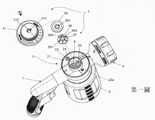
第一圖本發明組合與部分分解圖The first figure is the combination and partial exploded view of the present invention
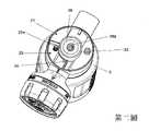
第二圖本發明部分組合圖The second figure is a partial combination diagram of the present invention
第三圖本發明轉盤立體圖The third figure is a perspective view of the turntable of the present invention
第四圖本發明組合與另一部分分解圖The fourth figure is the combination of the present invention and another part of the exploded view
第五圖本發明後蓋後視圖The fifth figure is the rear view of the rear cover of the present invention
第六圖本發明轉盤將Soap標誌對應定位標誌位置上視實施圖The sixth figure is the top view implementation view of the Soap mark corresponding to the positioning mark position on the turntable of the present invention
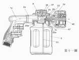
第七圖本發明部分剖視實施圖Figure 7 is a partial cross-sectional view of the implementation of the present invention
第八圖本發明部分另一剖視實施圖Figure 8: Another sectional view of the present invention part
第九圖本發明之閥件對應調整部之坡道的第一端的剖視實施圖Fig. 9 is a cross-sectional implementation view of the first end of the ramp corresponding to the adjusting portion of the valve member of the present invention
第十圖本發明揭示分流室與液體儲存室上視圖Figure 10 The present invention discloses the top view of the shunt chamber and the liquid storage chamber
第十一圖本發明剖視組合實施圖The eleventh figure is a cross-sectional combined implementation diagram of the present invention
第十二圖本發明上剖視實施圖The twelfth figure is the top cross-sectional implementation view of the present invention
第十三圖本發明部分放大剖視實施圖The thirteenth figure is a partial enlarged cross-sectional implementation view of the present invention
第十四圖本發明噴灑部放大剖視實施圖FIG. 14 is an enlarged cross-sectional view of the spraying portion of the present invention.
第十五圖本發明之閥件對應調整部之坡道的第二端的剖視實施圖Figure 15 is a cross-sectional implementation view of the valve element corresponding to the second end of the ramp of the adjusting portion of the present invention
第十六圖本發明轉盤將Water標誌對應定位標誌位置上視實施圖。Figure 16 is a top-view implementation view of the turntable of the present invention corresponding to the location of the Water mark.
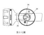
第十七圖本發明部份仰視剖視.實施圖Figure 17. Partial bottom section view of the present invention. Implementation drawing
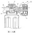
第十八圖本發明清水出水狀態實施圖The eighteenth figure is the implementation diagram of the state of clean water in the present invention
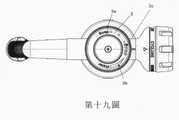
第十九圖本發明轉盤將Stop標誌對應定位標誌位置上視實施圖Figure 19 is a top view implementation view of the turntable of the present invention corresponding to the position of the stop mark
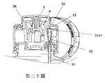
第二十圖發明之閥件對應坡道的鎖孔之剖視實施圖。Figure 20 is a cross-sectional implementation view of the valve element corresponding to the lock hole of the ramp of the invention.
為了充分瞭解本發明,以下將列舉較佳實例並配合附圖式作詳細說明,茲再配合本發明較佳實施例之圖式進一步說明如後,以期能使熟悉本發明相關技術之人士,得依本說明書之陳述據以實施,且其並非用以限定本發明之技術範圍。根據本發明,提供了一種可混合液體和調整濃度與流量與多種噴灑模式的一噴灑器,該噴灑器係可附接到一軟管的自由端,例如花園軟管,該軟管一端組接於一水龍頭,藉此該軟管提供傳送清水到噴灑器。In order to fully understand the present invention, preferred examples will be listed below and described in detail with the accompanying drawings, and further descriptions will be given in conjunction with the drawings of the preferred embodiments of the present invention. It is implemented according to the statement of this specification, and it does not limit the technical scope of the present invention. According to the present invention, there is provided a sprinkler that can mix liquids and adjust concentration and flow rates and multiple spray patterns, the sprinkler being attachable to the free end of a hose, such as a garden hose, which is assembled at one end at a faucet, whereby the hose provides delivery of clean water to the sprinkler.
以及,該噴灑器可以噴灑清水或混合液體與調整濃度與流量的轉換模式。And, the sprinkler can spray clean water or mixed liquid and adjust the concentration and flow conversion mode.
請參閱第一到第十一圖所示,該噴灑器結合一容器5,該容器5用於裝填液體並且設有一液體輸送管51,該液體輸送管51連結該噴灑器,所述液體可為濃縮的清潔液;以及,該容器5中的液體被噴灑器虹吸並到達噴灑器與清水進行混合稀釋形成泡沫噴出。Please refer to the first to eleventh figures, the sprinkler is combined with a
本發明噴灑器包括一操作部1、一殼體2、一調整部3與一噴灑部4;The sprinkler of the present invention includes an
該操作部1一端組接該軟管,其設有進水通道1a;One end of the
該殼體2具有一第一組接端與延伸的第二組接端與分流室A及多個分配通道及一檯面21,該第一組接端組裝於操作部1;以及,該分流室則被選擇對應連通該多個分配通道;The
以及,該殼體2之分流室A包括一第一分流口24與一第二分流口25,該第一分流口24與第二分流口25端面分別套設有一止水環;以及,該多個分配通道包括:第一分配通道2a及第二分配通道2b及第三分配通道2c,該分流室A是形成在第一分流口24與第二分流口25上端面位置的空間,該第一分流口24是連通該第一分配通道2a與該第二分配通道2b;以及;該第二分流口25設有延伸形成的一管道25a,該管道25a連通該第三分配通道2c;以及,該操作部1的進水通道1a連接該第一分配通道2a;And, the shunt chamber A of the
該檯面21一側設有一液體儲存室22,該液體儲存室22上端面具有封閉面以保持液體儲存室22成為液體暫存空間,其中液體儲存室22一端設有一虹吸通道52,其另一端設有一傳送通道29,該傳送通道29亦連通該第三分配通道2c;以及,該虹吸通道52組設一閥件22a,該閥件22a套設一彈簧22b,藉此該閥件22a可以在虹吸通道52中進行軸向上下位移與復位,其中該閥件22a具有頂端22a1與底端22a2;以及,該虹吸通道52連通該容器5的液體輸送管51,該虹吸通道52提供濃縮液傳輸到液體儲存室22,並由閥件22a來控制開啟虹吸通道52的出口大小,藉此控制該虹吸通道52內的液體進入液體儲存室22的流量大小與關閉該液體的輸送,該濃縮液到達液體儲存室22後再經傳送通道29傳輸到該第三分配通道2c;One side of the table 21 is provided with a
以及,該調整部3組接於殼體2,該調整部3組裝元件包括一轉盤31與一滑片38與一選擇件36,該轉盤31具有一組裝孔311,該組裝孔311一側具有一第一邊部312,該滑片38具有一穿孔381,該選擇件36徑邊一端設有一閥孔37,又該選擇件36中心延伸形成一柱部361,該柱部361往上端延伸形成一軸部362,該軸部362徑圓一邊具有一第二邊部363;該調整部3配置選擇件36使其能夠用手動旋轉以分流室A為軸心繞其軸線自由旋轉;And, the adjusting
該選擇件36置入該分流室A,並且該閥孔37可以對應選擇封閉該第一分流口24或第二分流口25;以及,該滑片38之穿孔381對合組套於該選擇件36之軸部362並抵靠於該柱部361之上端面,然後該滑片38緊密結合於該分流室A之端邊,藉此該選擇件36被限制於該分流室A位置處不會脫離,其中該軸部362是凸伸出於該滑片38,並且軸部362之第二邊部363對合轉盤31之組裝孔311的第一邊部312後置入後由一螺絲鎖合,藉此轉盤31可以在該檯面21上進行軸轉並同時軸轉動選擇件36;The
請參閱第三圖與第九圖與第十五圖所示,該調整部3的轉盤31設有一坡道32,該坡道32具有第一端32a與延伸的第二端32b及延伸的第三端32c,該第一端32a到第二端32b為逐漸升高的延伸坡面,且位於該第二端32b處設有一鎖孔33;以及,該第二端32b到第三端32c之間為延伸的等高;以及,該閥件22a頂端22a1對應頂抵於該坡道32,藉由該坡道32對應閥件22a以控制閥件22a的縱向上下位移位置;請參閱第三圖與第七圖及第八圖,在該坡道32對應一端設有環槽34;以及,該殼體2具有一空氣通道23,該空氣通道23的頂面設有一第一氣孔23a與底面設有一第二氣孔23b與,該第一氣孔23a連通該檯面21,該第二氣孔23b連通該容器5,且該第一氣孔23a套設一油封環,該油封環的面是頂抵於該轉盤31的環槽34處;Please refer to the third figure, the ninth figure and the fifteenth figure, the
請參閱第四圖與第五圖與第十八圖所示,該噴灑部4,其係包括一噴灑頭41與一後蓋42緊密結合組裝形成,該後蓋42緊密結合組接於殼體2之第二組接端;以及,該噴灑部4具有一混合通道2d與一清水通道2e,該混合通道2d延伸連接第三分配通道2c,該清水通道2e連接第二分配通道2b;以及,噴灑頭41設有多個清水噴口41a與一混合液噴口46,藉由手動轉動噴灑部4以選擇其中一清水噴口對應該清水通道2e,則可以噴灑出不同的噴灑模式,例如噴灑出單柱水花或者是放射狀水花等噴灑模式;以及,於實施例中該清水通道2e是形成於該後蓋42並可對應該噴灑頭41的任一清水噴口41a,但於本發明中不限制室設置於後蓋42,定義是該清水通道2e是對應噴灑部4被選擇的其中一清水噴口41a,且是接收由第一分流口24引流到該第二分配通道2b的清水;以及如第四圖與第五圖所示,該後蓋42具有一第一部位44,該第一部位44具有對應該噴灑頭41的混合液噴口46組套的置入孔45與多個入氣孔43,該入氣孔43是設置於接近該置入孔45周邊外圍,該置入孔45組設一組接嘴47,該組接嘴47是對應該混合液噴口46,且組接嘴47與混合液噴口46均設有對應的管道,該管道是分別供應稀釋液與泡沫液輸出。Please refer to Figure 4, Figure 5 and Figure 18, the
繼續請參閱第六圖到第十四圖為本發明噴出泡沫的實施圖,首先請參閱第六圖,轉動該調整部3之轉盤31使其(Soap)泡沫指示標誌3a對應定位標誌的位置處,該選擇件36之閥孔37對應該第二分流口25,並且封閉第一分流口24;繼續,轉盤31的環槽34是對應於第一氣孔23a,從而通過操作部1將水引入通過第一分配通道2a到該第二分流口25並因此產生負壓,藉此空氣由第一氣孔23a進入空氣通道23並由第二氣孔23b進入容器5內,該容器5內因空氣壓力而將液體經由液體輸送管51往虹吸通道52輸送,而形成虹吸效應將液體經液體輸送管51往上達到閥件22a處,此時如第九圖所示,該坡道32之第一端32a對應於該閥件22a的頂端22a1,閥件22a被彈簧22b往上頂起而使得閥件22a底端22a2開啟虹吸通道52,參閱第十一圖到第十四圖所示,該第二分流口25流出清水引流進入再由管道25a流入第三分配通道2c,同時液體進入液體儲存室22的由傳送通道29進入到達於第三分配通道2c處與由管道25a進入的清水混合為稀釋液,最後該稀釋的液體到達混合通道2d處時與由該入氣孔43進入的空氣經水流衝擊於混合通道2d處形成泡沫液體,最後從混合液噴口46噴出泡沫。Continue to refer to Figures 6 to 14 for the implementation of foam spraying according to the present invention. First, please refer to Figure 6. Turn the
因此,儘管描述了混合稀釋液體與空氣形成泡沫是在混合通道2d形成泡沫,但是該噴霧器的混合泡沫特定特徵,亦是可以在殼體2的多個分配通道之其中一個分配通道中完成,如該混合通道2d可為第三分配通道2c延伸到混合液噴口46的通道;該清水通道2e係可為第二分配通道2b延伸到清水噴口的通道。Therefore, although it is described that the foam is formed by mixing the dilution liquid and air to form the foam in the mixing
繼續,請參閱第六圖與第九圖及第十五圖,調整泡沫液濃度的實施例為,選擇轉動轉盤31使其(Soap)泡沫指示標誌3a中大到小指示標誌對應定位標誌,該坡道32之第一端32a到第二端32b是逐漸升高的延伸坡道,如第九圖所示該坡道32對應壓抵該閥件22a的頂端22a1時閥件22a是可被逐漸被往下壓,進而使得閥件22a底端22a2可以逐漸壓縮虹吸通道52出口大小,藉此以控制所述液體進入液體儲存室22流量由大到少,該閥件22a頂端22a1頂抵於該坡道32的第一端32a位置,則虹吸通道52出口開啟最大,因此液體大量進入液體儲存室22,再經液體儲存室22由傳送通道29進入到達於第三分配通道2c處同時與由管道25a進入的清水混合則產生較濃的稀釋液,最後該稀釋的液體到達混合通道2d處時與由該入氣孔43進入的空氣經水流衝擊混合形成濃泡沫液體,最後從混合液噴口46噴出較濃泡沫液;另一實施調整濃度如第十五圖所示,該閥件22a頂端22a1頂抵於該坡道32的第二端32b位置,則虹吸通道52出口開啟最小,因此液體少量進入液體儲存室22,再經液體儲存室22由傳送通道29進入到達於第三分配通道2c處同時與由管道25a進入的清水混合則產生較淡的稀釋液,最後該稀釋的液體到達混合通道2d處時與由該入氣孔43進入的空氣經水流衝擊混合形成淡泡沫液體,最後從混合液噴口46噴出較淡泡沫液。Continue, please refer to the sixth figure, the ninth figure and the fifteenth figure. An example of adjusting the concentration of the foam liquid is to select and rotate the
如上所述通過這種佈置,轉動轉盤31可以選擇濃縮液被虹吸進入液體儲存室22內的流量大小,進以控制調整噴灑泡沫的濃度模式。As described above, through this arrangement, rotating the
本發明調整僅噴出清水的模式請參閱第十六圖與第十七圖及第十八圖所示,轉動調整部3的轉盤31將(Water)水標誌對應定位標誌的位置處,此時該閥件22a是對應抵於該坡道32的第二端32b到第三端32c之間,所以該閥件22a是被下壓進而將該虹吸通道52出口封閉,同時該選擇件36之閥孔37對應該第一分流口24,並且封閉第二分流口25,通過操作部1將清水引入通過第一分配通道2a到分流室A,清水再由進入第一分流口24並導引到第二分配通道2b,繼續到達清水通道2e最後經由噴灑頭41被選擇的清水噴口41a噴出清水模式。Please refer to Figure 16, Figure 17 and Figure 18 for adjusting the mode in which only clean water is sprayed in the present invention. As shown in Figure 16, Figure 17 and Figure 18, rotate the
又,本發明停止泡沫噴灑模式實施例,如第十九圖與第二十圖所示,轉動調整部3的轉盤31將(stop)停止標誌3c對應定位標誌的位置處,該選擇件36同時封閉該第一分流口24與第二分流口25,轉盤31的坡道32之第二端32b之鎖孔33對應該閥件22a的頂端22a1嵌入,同時閥件22a是被往下壓而使得閥件22a底端22a2關閉虹吸通道52出口。In addition, the embodiment of the present invention to stop the foam spraying mode, such as the nineteenth and the twentiethAs shown in the figure, the
簡述本發明的特徵結構與噴灑流道過程是,該噴灑部4組接於該殼體2,其設有清水通道2e與混合通道2d,該分流部A可被選擇連通該清水通道2e或混合通道2d;以及,該噴灑頭41是可被手動轉動;以及,該多個清水噴口41a係環繞該混合液噴口46配置,且手動轉動該噴灑頭41以選擇其中之一清水噴口41a對應該清水通道2e;以及,該混合液噴口46係對應該混合通道2d;以及,藉由手動轉動該調整部3對應分流部A,以選擇將清水流向被選擇的其中一清水噴口41a以噴灑出不同的清水噴灑模式;以及,手動轉動該調整部3對應分流部A以選擇將清水與液體輸入該混合通道2d,則混合形成混合液體由該混合液噴口46噴灑出混合液模式。Briefly describe the characteristic structure of the present invention and the process of spraying the flow channel, the spraying
綜上所述本發明優選地於具有以下多種不同的操作模式:In summary, the present invention preferably has the following various operating modes:
模式1:清水經分流室A進入第一分流口24,僅供應噴灑清水沖洗模式,其由被選擇的其中之一清水噴口41a噴出清水。Mode 1: Clear water enters the
模式2:清水經分流室A由第二分流口25與選定由容器5中抽吸的液體於殼體2的通道中與清水混合,該混合液到達噴灑部4混合外部空氣形成泡沫液,供應噴灑出泡沫沖洗模式,其由混合液噴口46噴出泡沫。Mode 2: The clean water is mixed with the clean water in the channel of the
模式3:選擇轉盤31以調整流量大小,藉由該轉盤31的坡道32設計,可以提供無段式調整閥件22a開啟虹吸通道52的出口流量大小,藉此液體供應進入殼體2之液體儲存室22的流量大小可以被調整,所以液體供應的流量大小與清水混合,進以控制液體與清水的混合濃度,而產生的泡沫濃度就可以調整。Mode 3: Select the
模式4:的供應噴灑出泡沫濃度或清水的流量大小沖洗模式。Mode 4: The flushing mode of supply spraying out the foam concentration or the flow size of clean water.
模式5:選定停止,關閉第一分流口24與第二分流口25,則為關閉無法噴灑模式。Mode 5: Select stop and close the
如上所述,本發明的優點在模式3中的調整液體濃度噴灑模式,由於可以選擇虹吸濃縮液體的流量大小,因此濃縮液體與清水混合的稀釋濃度是可以被選擇的。As mentioned above, the advantage of the present invention lies in the adjustment of the liquid concentration spraying mode in
這裡已經描述和示出了噴霧器組件的實施例,儘管已經描述了本發明的特定實施例,但是並不意圖將本發明限制於此,在本發明中的混合液形成泡沫為實施的範例並非限制本發明的使用實施範圍,因為意圖是本發明的範圍應在本領域所允許的範圍之內,並且說明書也應被同樣地閱讀。Embodiments of the nebulizer assembly have been described and illustrated herein, and although specific embodiments of the invention have been described, it is not intended to limit the invention thereto, and the foaming of the mixture in the invention is not a limitation The scope of the use of the present invention is intended to be within the scope of the present invention as permitted in the art, and the specification should be read as such.
1:操作部1: Operation Department
2:殼體2: Shell
3:調整部3: Adjustment Department
4:噴灑部4: Spray part
A:分流室A: Shunt Room
21:檯面21: Countertops
22a:閥件22a: Valves
23:空氣通道23: Air channel
24:第一分流口24: The first shunt
25:第二分流口25: Second shunt port
31:轉盤31: Turntable
311:組裝孔311: Assembly hole
312:第一邊部312: First side
36:選擇件36: Select Pieces
361柱部361 pillar
362:軸部362: Shaft
363:第二邊部363: Second side
37:閥孔37: Valve hole
38:滑片38: Slider
381:穿孔381: Perforation
5:容器5: Container
Claims (12)
Translated fromChinesePriority Applications (9)
| Application Number | Priority Date | Filing Date | Title |
|---|---|---|---|
| TW110109556ATWI766620B (en) | 2021-03-17 | 2021-03-17 | Sprinkler with adjustable flow of mixed liquid and clean water |
| AU2021202772AAU2021202772A1 (en) | 2021-03-17 | 2021-05-03 | Sprayer Able to Adjust Flow of Mixed Solution and Clear Water |
| GB2106567.7AGB2596638B (en) | 2021-03-17 | 2021-05-07 | Sprayer able to adjust flow of mixed solution and clear water |
| PL21173132.8TPL4059613T3 (en) | 2021-03-17 | 2021-05-10 | SPRAYER WITH THE POSSIBILITY OF ADJUSTING THE FLOW OF MIXED SOLUTION AND CLEAN WATER |
| EP21173132.8AEP4059613B1 (en) | 2021-03-17 | 2021-05-10 | Sprayer able to adjust flow of mixed solution and clear water |
| CA3118310ACA3118310C (en) | 2021-03-17 | 2021-05-13 | Sprayer able to adjust flow of mixed solution and clear water |
| JP2021083007AJP7339681B2 (en) | 2021-03-17 | 2021-05-17 | Sprinkler that can adjust the flow rate of mixed liquid and purified water |
| US17/344,908US11607697B2 (en) | 2021-03-17 | 2021-06-10 | Sprayer able to adjust flow of mixed solution and water |
| AU2023202789AAU2023202789B2 (en) | 2021-03-17 | 2023-05-04 | Sprayer Able to Adjust Flow of Mixed Solution and Clear Water |
Applications Claiming Priority (1)
| Application Number | Priority Date | Filing Date | Title |
|---|---|---|---|
| TW110109556ATWI766620B (en) | 2021-03-17 | 2021-03-17 | Sprinkler with adjustable flow of mixed liquid and clean water |
Publications (2)
| Publication Number | Publication Date |
|---|---|
| TWI766620Btrue TWI766620B (en) | 2022-06-01 |
| TW202237276A TW202237276A (en) | 2022-10-01 |
Family
ID=75904762
Family Applications (1)
| Application Number | Title | Priority Date | Filing Date |
|---|---|---|---|
| TW110109556ATWI766620B (en) | 2021-03-17 | 2021-03-17 | Sprinkler with adjustable flow of mixed liquid and clean water |
Country Status (8)
| Country | Link |
|---|---|
| US (1) | US11607697B2 (en) |
| EP (1) | EP4059613B1 (en) |
| JP (1) | JP7339681B2 (en) |
| AU (2) | AU2021202772A1 (en) |
| CA (1) | CA3118310C (en) |
| GB (1) | GB2596638B (en) |
| PL (1) | PL4059613T3 (en) |
| TW (1) | TWI766620B (en) |
Families Citing this family (1)
| Publication number | Priority date | Publication date | Assignee | Title |
|---|---|---|---|---|
| CN114586522B (en)* | 2022-04-07 | 2023-05-26 | 钱江源-百山祖国家公园龙泉保护中心 | Backpack type bamboo stump pesticide spraying machine and pesticide spraying method thereof |
Citations (3)
| Publication number | Priority date | Publication date | Assignee | Title |
|---|---|---|---|---|
| CN102209593A (en)* | 2008-09-09 | 2011-10-05 | 水源集团公司 | sprayer |
| TWM549660U (en)* | 2017-07-06 | 2017-10-01 | Zhyi Int Ltd | Water gun structure allowing detergent blending |
| US20200290064A1 (en)* | 2019-03-14 | 2020-09-17 | Hangzhou Weirran Machinery Co., Ltd | Multi-mode high-pressure foam lance |
Family Cites Families (69)
| Publication number | Priority date | Publication date | Assignee | Title |
|---|---|---|---|---|
| FR1182266A (en)* | 1957-04-15 | 1959-06-24 | Automatic valve with emulsion pump | |
| US3254844A (en) | 1964-03-11 | 1966-06-07 | Internat Patent Res Corp | Aspiration spray device |
| GB1482149A (en)* | 1973-10-19 | 1977-08-03 | Acme General Corp | Spray apparatus |
| US3940069A (en) | 1974-09-30 | 1976-02-24 | Meiko, Incorporated | Spray apparatus |
| FR2296472A1 (en)* | 1975-01-03 | 1976-07-30 | Sablons Fonderie Et Ateliers | DEVICE FOR MIXING AND SPRAYING LIQUID PRODUCTS |
| US4369921A (en)* | 1980-12-12 | 1983-01-25 | Acme Burgess, Inc. | Hose-end sprayer |
| US4475689A (en)* | 1982-12-09 | 1984-10-09 | R. M. Smith, Inc. | Variable dilution ratio hose-end sprayer |
| US4708292A (en) | 1985-06-05 | 1987-11-24 | Olin Corporation | Foam dispensing gun with improved mixing chamber |
| US4736891A (en)* | 1986-07-28 | 1988-04-12 | Hunter-Melnor, Inc. | Aspiration-type sprayer |
| US5213265A (en)* | 1991-03-18 | 1993-05-25 | Hayes Products L.P. | Single valve aspiration type sprayer |
| US5445288A (en) | 1994-04-05 | 1995-08-29 | Sprintvest Corporation Nv | Liquid dispenser for dispensing foam |
| US5595345A (en) | 1995-05-26 | 1997-01-21 | Armor All Products Corporation | Double barrel sprayer for selective spraying of water or diluted product and use thereof |
| US5755384A (en) | 1995-08-01 | 1998-05-26 | Contico International, Inc. | Dispenser with selectable discharge nozzle |
| US5881955A (en) | 1997-04-17 | 1999-03-16 | Monsanto Company | Spraying device |
| JP2990351B2 (en)* | 1997-12-27 | 1999-12-13 | 正治 三宅 | Sprinkler tap for chemical dilution |
| US6425534B2 (en)* | 1998-11-05 | 2002-07-30 | Green Garden Products Company | Spraying apparatus having a sealing member with apertures |
| US6283385B1 (en)* | 1999-01-22 | 2001-09-04 | Griffin Llc | Method and apparatus for dispensing multiple-component flowable substances |
| US6578776B1 (en) | 2000-04-03 | 2003-06-17 | Hayes Products, Llc. | Single valve ready to use hose end sprayer |
| US6869028B2 (en)* | 2000-06-14 | 2005-03-22 | The Procter & Gamble Company | Spraying device |
| US6726123B2 (en)* | 2002-01-04 | 2004-04-27 | Yuan Mei Corp. | Operating/controlling structure of detergent-mixable sprinkling gun |
| US6772966B2 (en)* | 2002-04-10 | 2004-08-10 | Continental Afa Dispensing Company | Adjustable hose end sprayer nozzle |
| US7494073B2 (en) | 2003-03-25 | 2009-02-24 | Alexander Pivovarov | Cleaning of submerged surfaces by discharge of pressurized cavitating fluids |
| US7721977B2 (en) | 2003-04-09 | 2010-05-25 | Diversified Dynamics Corporation | Vibration reduction pad for hand-held paint spray guns |
| US7004356B1 (en) | 2003-07-28 | 2006-02-28 | Joseph S. Kanfer | Foam producing pump with anti-drip feature |
| US7118049B2 (en)* | 2003-10-30 | 2006-10-10 | Meadwestvaco Corporation | Hose-end sprayer assembly |
| US6966503B1 (en) | 2004-01-09 | 2005-11-22 | Shin Tai Spurt Water Of The Garden Tools Co., Ltd. | Sprinkler provided with a built-in mechanism for dispensing detergent |
| US7350722B2 (en) | 2004-02-11 | 2008-04-01 | Meadwestvaco Calmar, Inc. | Single valve ready to use sprayer |
| US7229030B2 (en) | 2004-02-13 | 2007-06-12 | Hayes Products, Llc. | Single valve ready to use hose end sprayer |
| US8201755B2 (en) | 2004-02-20 | 2012-06-19 | Meadwestvaco Calmar, Inc. | Single valve ready to use sprayer |
| US7631819B2 (en) | 2004-02-27 | 2009-12-15 | Meadwestvaco Calmar, Inc. | Longitudinal valve ready to use hose end sprayer |
| US20050211280A1 (en) | 2004-03-25 | 2005-09-29 | David Liu | Multifunction vehicular surface cleaning system |
| US7407117B2 (en) | 2004-10-28 | 2008-08-05 | Meadwestvaco Calmar, Inc. | Liquid sprayer assembly |
| US8608091B2 (en) | 2005-03-18 | 2013-12-17 | 3M Innovative Properties Company | Dispensing gun assembly for mixing and dispensing plural component foam |
| CA2504989C (en) | 2005-04-22 | 2013-03-12 | Gotohti.Com Inc. | Stepped pump foam dispenser |
| US7237728B1 (en) | 2005-05-19 | 2007-07-03 | Rodney Laible | Hand-held dispenser |
| US7124962B1 (en) | 2005-05-24 | 2006-10-24 | S.C. Johnson & Son, Inc. | Sprayer for cleaning exterior surfaces |
| US7753288B2 (en)* | 2005-11-08 | 2010-07-13 | Maclean-Blevins Mark T | System for failsafe controlled dispensing of liquid material |
| US7866626B1 (en)* | 2006-03-01 | 2011-01-11 | Mark Maclean-Blevins | Hydraulically controlled in-line valve apparatus |
| US7661604B1 (en)* | 2006-03-16 | 2010-02-16 | Maclean-Blevins Mark T | System and method for controlled dosing and dispensing of liquid material |
| US7445167B1 (en)* | 2007-01-10 | 2008-11-04 | Shin Tai Spurt Water Of The Garden Tools Co., Ltd. | Spraying gun for washing car |
| US20080296398A1 (en)* | 2007-01-11 | 2008-12-04 | Ralph Hickman | Systems and methods for spraying water and mixtures of water and other materials |
| WO2008130352A1 (en)* | 2007-04-24 | 2008-10-30 | Rodney Laible | Hand-held dispenser |
| US8499981B2 (en) | 2008-02-08 | 2013-08-06 | Gojo Industries, Inc. | Bifurcated stem foam pump |
| ES2357734T3 (en) | 2008-05-29 | 2011-04-29 | Gojo Industries, Inc. | TRUMP OPERATED FOAM PUMP. |
| EP2373428B1 (en) | 2008-12-23 | 2018-08-15 | OMS Investments, Inc. | Sprayer |
| US20140076996A1 (en) | 2010-10-08 | 2014-03-20 | Tyco Fire & Security Gmbh | Spray gun and portable mist-generating apparatus |
| USD670982S1 (en) | 2011-03-01 | 2012-11-20 | Smg Brands, Inc. | Applicator |
| USD650046S1 (en) | 2011-03-01 | 2011-12-06 | Smg Brands, Inc. | Sprayer |
| US20120223161A1 (en) | 2011-03-01 | 2012-09-06 | Smg Brands, Inc. | Ready-to-use hose end sprayer |
| US20120223160A1 (en) | 2011-03-01 | 2012-09-06 | Smg Brands, Inc. | Applicator with collapsible wand |
| US8814005B2 (en) | 2012-04-27 | 2014-08-26 | Pibed Limited | Foam dispenser |
| US8726939B2 (en)* | 2012-05-07 | 2014-05-20 | Rl Innovations, Llc | Hand-held dispenser |
| CN103056054B (en)* | 2013-01-29 | 2015-07-22 | 厦门建霖工业有限公司 | Multifunctional distributor |
| USD708301S1 (en) | 2013-03-15 | 2014-07-01 | Oms Investments, Inc. | Liquid sprayer |
| US9630767B2 (en) | 2013-05-14 | 2017-04-25 | Icp Adhesives And Sealants, Inc. | Temperature indicating foam gun nozzles and hoses |
| US9950302B1 (en) | 2014-01-13 | 2018-04-24 | Crossford International, Llc | Stand-alone chemical dispenser |
| US9663927B2 (en)* | 2014-06-26 | 2017-05-30 | Yuan-Mei Corp. | Faucet diverter |
| US9561516B2 (en) | 2014-07-28 | 2017-02-07 | Westly S. Decker | Liquid sprayer for plants |
| USD742998S1 (en) | 2014-08-11 | 2015-11-10 | Hopkins Manufacturing Corporation | Sprayer |
| US10173230B2 (en) | 2014-09-11 | 2019-01-08 | Mtm Hydro S.R.L. | Foam generating device for a high-pressure water gun |
| US10486176B2 (en)* | 2015-07-02 | 2019-11-26 | Silgan Dispensing Systems Corporation | Dosing dispensers and methods for using the same |
| CN107921452B (en) | 2015-09-02 | 2020-07-03 | 罗门哈斯公司 | Cleanout adapter and method for foam gun dispensers |
| EP3352905B1 (en)* | 2015-09-21 | 2022-12-07 | S.C. Johnson & Son, Inc. | System for mixing and dispensing |
| CN106423614B (en)* | 2016-07-21 | 2022-07-12 | 苏州力奇研发有限公司 | Adjustable foam generating sprayer |
| US20180043379A1 (en) | 2016-08-09 | 2018-02-15 | Icp Adhesives And Sealants, Inc. | Re-Orientable Spray Foam Gun Nozzles |
| US20180085766A1 (en) | 2016-09-27 | 2018-03-29 | Icp Adhesives And Sealants, Inc. | Foam Dispensing Gun with Third Stream |
| US10582830B2 (en) | 2017-10-06 | 2020-03-10 | Rita Fasson | Handheld retractable cleaning sprayer |
| CN214257726U (en)* | 2020-12-18 | 2021-09-24 | 余姚市中裕灌溉设备有限公司 | Spraying device and spraying system with same |
| TWI754565B (en)* | 2021-03-17 | 2022-02-01 | 源美股份有限公司 | Sprinkler for spraying mixed liquid and clean water |
- 2021
- 2021-03-17TWTW110109556Apatent/TWI766620B/enactive
- 2021-05-03AUAU2021202772Apatent/AU2021202772A1/ennot_activeAbandoned
- 2021-05-07GBGB2106567.7Apatent/GB2596638B/enactiveActive
- 2021-05-10EPEP21173132.8Apatent/EP4059613B1/enactiveActive
- 2021-05-10PLPL21173132.8Tpatent/PL4059613T3/enunknown
- 2021-05-13CACA3118310Apatent/CA3118310C/enactiveActive
- 2021-05-17JPJP2021083007Apatent/JP7339681B2/enactiveActive
- 2021-06-10USUS17/344,908patent/US11607697B2/enactiveActive
- 2023
- 2023-05-04AUAU2023202789Apatent/AU2023202789B2/enactiveActive
Patent Citations (3)
| Publication number | Priority date | Publication date | Assignee | Title |
|---|---|---|---|---|
| CN102209593A (en)* | 2008-09-09 | 2011-10-05 | 水源集团公司 | sprayer |
| TWM549660U (en)* | 2017-07-06 | 2017-10-01 | Zhyi Int Ltd | Water gun structure allowing detergent blending |
| US20200290064A1 (en)* | 2019-03-14 | 2020-09-17 | Hangzhou Weirran Machinery Co., Ltd | Multi-mode high-pressure foam lance |
Also Published As
| Publication number | Publication date |
|---|---|
| EP4059613A1 (en) | 2022-09-21 |
| AU2023202789A1 (en) | 2023-05-25 |
| CA3118310A1 (en) | 2022-09-17 |
| GB2596638A (en) | 2022-01-05 |
| JP2022145389A (en) | 2022-10-04 |
| CA3118310C (en) | 2023-09-12 |
| TW202237276A (en) | 2022-10-01 |
| US11607697B2 (en) | 2023-03-21 |
| EP4059613B1 (en) | 2023-09-27 |
| AU2023202789B2 (en) | 2025-05-01 |
| AU2021202772A1 (en) | 2022-10-06 |
| JP7339681B2 (en) | 2023-09-06 |
| PL4059613T3 (en) | 2024-03-11 |
| GB2596638B (en) | 2022-09-28 |
| US20220297144A1 (en) | 2022-09-22 |
Similar Documents
| Publication | Publication Date | Title |
|---|---|---|
| TWI754565B (en) | Sprinkler for spraying mixed liquid and clean water | |
| US5850973A (en) | Double barrel sprayer for selective spraying of water or diluted product and use thereof | |
| US7407117B2 (en) | Liquid sprayer assembly | |
| JP3542609B2 (en) | Improved spray device | |
| US20210276856A1 (en) | Coupler for Use in a Closed Transfer System | |
| US20080197214A1 (en) | Variable water flow and dilution chemical dispenser | |
| WO1996037261A9 (en) | Double barrel sprayer | |
| US5058220A (en) | Jet nozzle apparatus | |
| US12023704B2 (en) | Wet/dry hose end sprayer | |
| TWI766620B (en) | Sprinkler with adjustable flow of mixed liquid and clean water | |
| US20050178858A1 (en) | Liquid spraying pistol with variable jet for gardening | |
| MXPA97008924A (en) | Double bar sprayer |