TWI765716B - Supporting hook structure for femoral surgery - Google Patents
Supporting hook structure for femoral surgeryDownload PDFInfo
- Publication number
- TWI765716B TWI765716BTW110118332ATW110118332ATWI765716BTW I765716 BTWI765716 BTW I765716BTW 110118332 ATW110118332 ATW 110118332ATW 110118332 ATW110118332 ATW 110118332ATW I765716 BTWI765716 BTW I765716B
- Authority
- TW
- Taiwan
- Prior art keywords
- hole
- groove
- femoral
- fixing
- sleeve
- Prior art date
Links
- 238000001356surgical procedureMethods0.000titleabstractdescription13
- 210000000689upper legAnatomy0.000claimsabstractdescription31
- 238000006073displacement reactionMethods0.000claimsdescription6
- 238000003780insertionMethods0.000claimsdescription2
- 230000037431insertionEffects0.000claimsdescription2
- 210000003205muscleAnatomy0.000abstractdescription11
- 238000000034methodMethods0.000description11
- 210000004872soft tissueAnatomy0.000description10
- 230000006378damageEffects0.000description9
- 230000008901benefitEffects0.000description6
- 230000008569processEffects0.000description5
- 238000010586diagramMethods0.000description4
- 210000001503jointAnatomy0.000description4
- 230000000451tissue damageEffects0.000description4
- 231100000827tissue damageToxicity0.000description4
- 208000027418Wounds and injuryDiseases0.000description3
- 238000011882arthroplastyMethods0.000description3
- 230000008859changeEffects0.000description3
- 210000000109fascia lataAnatomy0.000description3
- 210000001624hipAnatomy0.000description3
- 208000014674injuryDiseases0.000description3
- 230000007246mechanismEffects0.000description3
- 230000002980postoperative effectEffects0.000description3
- 230000000694effectsEffects0.000description2
- 210000004394hip jointAnatomy0.000description2
- 238000011084recoveryMethods0.000description2
- 230000004044responseEffects0.000description2
- 210000000588acetabulumAnatomy0.000description1
- 210000000988bone and boneAnatomy0.000description1
- 201000010099diseaseDiseases0.000description1
- 208000037265diseases, disorders, signs and symptomsDiseases0.000description1
- 210000000527greater trochanterAnatomy0.000description1
- 238000011540hip replacementMethods0.000description1
- 230000003902lesionEffects0.000description1
- 239000007769metal materialSubstances0.000description1
- 230000002035prolonged effectEffects0.000description1
- 210000003314quadriceps muscleAnatomy0.000description1
- 230000000717retained effectEffects0.000description1
- 230000001225therapeutic effectEffects0.000description1
- 210000001519tissueAnatomy0.000description1
- 238000011541total hip replacementMethods0.000description1
Images


Classifications
- A—HUMAN NECESSITIES
- A61—MEDICAL OR VETERINARY SCIENCE; HYGIENE
- A61B—DIAGNOSIS; SURGERY; IDENTIFICATION
- A61B17/00—Surgical instruments, devices or methods
- A61B17/02—Surgical instruments, devices or methods for holding wounds open, e.g. retractors; Tractors
- A61B17/025—Joint distractors
- A—HUMAN NECESSITIES
- A61—MEDICAL OR VETERINARY SCIENCE; HYGIENE
- A61B—DIAGNOSIS; SURGERY; IDENTIFICATION
- A61B90/00—Instruments, implements or accessories specially adapted for surgery or diagnosis and not covered by any of the groups A61B1/00 - A61B50/00, e.g. for luxation treatment or for protecting wound edges
- A61B90/03—Automatic limiting or abutting means, e.g. for safety
- A—HUMAN NECESSITIES
- A61—MEDICAL OR VETERINARY SCIENCE; HYGIENE
- A61F—FILTERS IMPLANTABLE INTO BLOOD VESSELS; PROSTHESES; DEVICES PROVIDING PATENCY TO, OR PREVENTING COLLAPSING OF, TUBULAR STRUCTURES OF THE BODY, e.g. STENTS; ORTHOPAEDIC, NURSING OR CONTRACEPTIVE DEVICES; FOMENTATION; TREATMENT OR PROTECTION OF EYES OR EARS; BANDAGES, DRESSINGS OR ABSORBENT PADS; FIRST-AID KITS
- A61F2/00—Filters implantable into blood vessels; Prostheses, i.e. artificial substitutes or replacements for parts of the body; Appliances for connecting them with the body; Devices providing patency to, or preventing collapsing of, tubular structures of the body, e.g. stents
- A61F2/02—Prostheses implantable into the body
- A61F2/30—Joints
- A61F2/46—Special tools for implanting artificial joints
- A61F2/4603—Special tools for implanting artificial joints for insertion or extraction of endoprosthetic joints or of accessories thereof
- A61F2/4607—Special tools for implanting artificial joints for insertion or extraction of endoprosthetic joints or of accessories thereof of hip femoral endoprostheses
- A—HUMAN NECESSITIES
- A61—MEDICAL OR VETERINARY SCIENCE; HYGIENE
- A61B—DIAGNOSIS; SURGERY; IDENTIFICATION
- A61B17/00—Surgical instruments, devices or methods
- A61B2017/00367—Details of actuation of instruments, e.g. relations between pushing buttons, or the like, and activation of the tool, working tip, or the like
- A—HUMAN NECESSITIES
- A61—MEDICAL OR VETERINARY SCIENCE; HYGIENE
- A61B—DIAGNOSIS; SURGERY; IDENTIFICATION
- A61B17/00—Surgical instruments, devices or methods
- A61B17/02—Surgical instruments, devices or methods for holding wounds open, e.g. retractors; Tractors
- A61B17/025—Joint distractors
- A61B2017/0275—Joint distractors for the hip
- A—HUMAN NECESSITIES
- A61—MEDICAL OR VETERINARY SCIENCE; HYGIENE
- A61B—DIAGNOSIS; SURGERY; IDENTIFICATION
- A61B90/00—Instruments, implements or accessories specially adapted for surgery or diagnosis and not covered by any of the groups A61B1/00 - A61B50/00, e.g. for luxation treatment or for protecting wound edges
- A61B90/50—Supports for surgical instruments, e.g. articulated arms
- A61B90/57—Accessory clamps
- A61B2090/571—Accessory clamps for clamping a support arm to a bed or other supports
Landscapes
- Health & Medical Sciences (AREA)
- Life Sciences & Earth Sciences (AREA)
- Surgery (AREA)
- General Health & Medical Sciences (AREA)
- Public Health (AREA)
- Biomedical Technology (AREA)
- Heart & Thoracic Surgery (AREA)
- Veterinary Medicine (AREA)
- Engineering & Computer Science (AREA)
- Animal Behavior & Ethology (AREA)
- Molecular Biology (AREA)
- Nuclear Medicine, Radiotherapy & Molecular Imaging (AREA)
- Medical Informatics (AREA)
- Orthopedic Medicine & Surgery (AREA)
- Transplantation (AREA)
- Oral & Maxillofacial Surgery (AREA)
- Physical Education & Sports Medicine (AREA)
- Cardiology (AREA)
- Vascular Medicine (AREA)
- Pathology (AREA)
- Surgical Instruments (AREA)
- Prostheses (AREA)
Abstract
Description
Translated fromChinese本發明是關於外科手術之醫療器材技術領域,特別是關於一種用於股骨手術用股骨拉鈎結構。The present invention relates to the technical field of medical equipment for surgery, in particular to a femoral retractor structure for femoral surgery.
於現今,人工關節置換是一項重要的外科手術。人工關節的關節置換是指用生物相容性和機械性能良好的金屬材料製成的一種類似人體骨關節的替代體,利用手術方法將人工關節置換因為疾病侵蝕或外力損傷的關節,其目的是矯正病灶,清除疼痛,恢復關節的活動與本質的功能。人工關節置換術的治療效果經過近六十年的臨床實踐,已經得到充分的肯定和已經發展成為一種可靠的治療手段。Artificial joint replacement is an important surgical procedure today. Joint replacement of artificial joints refers to a kind of substitute body similar to human bone joints made of metal materials with good biocompatibility and mechanical properties. The purpose of using artificial joints to replace joints that are eroded by diseases or damaged by external forces is to use surgical methods. Correct the lesion, clear the pain, and restore the activity and essential function of the joint. After nearly 60 years of clinical practice, the therapeutic effect of artificial joint replacement has been fully affirmed and developed into a reliable treatment method.
傳統的方式是採用將工具前部尖端插入碗形的邊緣,醫生手持後端,用力撬開髖臼,露出股骨頭。但是這種撬開的方式,醫生著力不方便,而且前部尖端插入碗形的邊緣後可能產生滑移,導致髖關節或周圍組織造成傷害。The traditional method is to insert the front tip of the tool into the rim of the bowl, and the doctor holds the rear end and forcefully prys open the acetabulum to expose the femoral head. However, this method of prying is inconvenient for the doctor to focus on, and the front tip may slip when inserted into the edge of the bowl, causing injury to the hip joint or surrounding tissue.
現階段之直接前側入路髖關節置換手術(Direct Anterior Approach,DAA)是目前應用日益廣泛的微創全髖關節置換手術入路。與傳統手術相比,DAA入路下的全髖關節置換術是從闊筋膜張肌和股直肌間隙入路顯露髖關節,具有軟組織損傷小,術後恢復快,住院時間短等優點,早期療效明顯。目前已有多項大樣本研究數據表明DAA入路下的全髖關節置換術可顯著促進患者術後的加速康復。The current direct anterior approach hip replacement surgery (Direct Anterior Approach, DAA) is currently an increasingly widely used minimally invasive total hip replacement surgery approach. Compared with traditional surgery, total hip arthroplasty under the DAA approach is performed from the space between the tensor fascia lata and rectus femoris.The exposed hip joint has the advantages of less soft tissue damage, quick postoperative recovery, short hospital stay, etc., and the early curative effect is obvious. A number of large-sample studies have shown that total hip arthroplasty under the DAA approach can significantly promote postoperative accelerated recovery.
在DAA入路下的全髖關節置換的手術過程中,股骨近端的顯露是至關重要的一個步驟。目前的做法主要是將一個大轉子雙叉拉鈎置於股骨近端與後方肌肉之間,以闊筋膜張肌與皮膚等軟組織複合體為支點,通過撬動的方式,下壓雙叉拉鈎尾端,上抬股骨近端至傾斜15度左右。而目前醫院內部相相應的裝置,通過人力長時間拉抬需要很大的力量,非常困難,且並發症很多。The exposure of the proximal femur is a crucial step in the surgical procedure of total hip arthroplasty under the DAA approach. The current practice is to place a greater trochanter bifurcated retractor between the proximal end of the femur and the posterior muscle, with the soft tissue complex such as the tensor fascia lata and the skin as the fulcrum, and by prying, the bifurcated retractor is pressed down. Hook caudal end, raise the proximal femur to about 15 degrees of inclination. At present, the corresponding device in the hospital requires a lot of force to be pulled by manpower for a long time, which is very difficult and has many complications.
然而這種手術方式存在很大的弊端,在撬動的過程中,闊筋膜張肌會受到較大的力,一些老年患者因軟組織結構較為疏鬆,下壓雙叉拉鈎的過程中,容易出現肌肉撕裂、軟組織過度損傷等現象,因此非常不利於患者術後的康復和功能鍛煉。However, this surgical method has great drawbacks. In the process of prying, the tensor fascia lata will be subjected to a large force. Some elderly patients have loose soft tissue structure. During the process of pressing the bifurcated retractor, it is easy to Muscle tearing and excessive soft tissue damage occur, which is very unfavorable for postoperative rehabilitation and functional exercise of patients.
又,在置換手術中,主要是通過小切口開始進行,其涉及到軟組織的剝離,股骨頭的截取等。在手術過程中,拉鈎的為非常關鍵的手術工具。現有拉鈎為通常直角拉鈎,使用時需要與敲擊器配合使用。具體使用時,需要三隻手來進行,其中,一隻手用來控制拉鈎,另一隻手用來控制敲擊器,第三隻手用來敲擊,且拉鈎還需要配合抬起角度之股骨近端進行貼靠於股骨大轉子下方,使用起來非常繁瑣,致使手術時間變長了。In addition, in replacement surgery, it is mainly performed through a small incision, which involves peeling of soft tissue, cutting of the femoral head, and the like. During surgery, the retractor is a very critical surgical tool. The existing draw hook is usually a right-angle draw hook, which needs to be used in conjunction with a knocker. For specific use, three hands are required, of which one hand is used to control the retractor, the other hand is used to control the striker, and the third hand is used to strike, and the retractor also needs to match the lift angle of the femur near the femur. It is very cumbersome to use and the operation time is prolonged.
有鑑於前述中所存在的缺點,本發明之一目的在提高手術過程中拉鈎的易用度,使拉鈎可以快速地被貼靠於貼靠於股骨大轉子下方,達到支撐作用。本發明提供一種股骨拉鈎結構,用於手術中支撐人體內之股骨,其包括有:一套筒、一固定桿、一第一限位單元、一鈎體。In view of the above-mentioned shortcomings, one objective of the present invention is to improve the ease of use of the retractor during the operation, so that the retractor can be quickly pressed against the lower trochanter of the femur to achieve support. The present invention provides a femoral retractor structure, which is used for supporting the femur in the human body during surgery, which comprises: a sleeve, a fixing rod, a first limiting unit, and a hook body.
該固定桿之一端連接於該套筒上。One end of the fixing rod is connected to the sleeve.
該第一限位單元設置於該套筒上。The first limiting unit is arranged on the sleeve.
該鈎體包括有一鈎部、一連接部以及第二限位單元,該連接部之一端與該鈎部一端相接,該第二限位單元設於該連接部。The hook body includes a hook portion, a connecting portion and a second limiting unit, one end of the connecting portion is connected with one end of the hook portion, and the second limiting unit is arranged on the connecting portion.
其中,當該連接部之另一端連接該套筒時,該第一限位單元與該第二限位單元連接,使得該鈎體以該套筒之一軸心方向為旋轉軸進行一第一旋轉位移運動。Wherein, when the other end of the connecting portion is connected to the sleeve, the first limiting unit is connected with the second limiting unit, so that the hook body performs a first rotation with an axial direction of the sleeve as the rotation axis Rotational displacement movement.
進一步地,該第一限位單元為一限位凸塊,以及該第二限位單元包括有一溝槽以及一限位凹槽,該限位凹槽環設於該連接部之側面且鄰靠該鈎部,該溝槽設於該連接部之側面,該溝槽自該連接部之另一端延該軸心方向延伸且與該限位凹槽相連接,該連接部之另一端連接該套筒時,該限位凸塊延該溝槽移動至該限位凹槽,使得該鈎體以該軸心方向為旋轉軸進行該第一旋轉位移運動。Further, the first limiting unit is a limiting protrusion, and the second limiting unit includes a groove and a limiting groove, and the limiting groove is annularly arranged on the side surface of the connecting portion and abuts against the hook part, the groove is arranged on the side of the connecting part, the groove extends from the other end of the connecting part in the axial direction and is connected with the limiting groove, and the other end of the connecting part is connected to the sleeve When the cylinder is installed, the limiting protrusion moves to the limiting groove along the groove, so that the hook body performs the first rotational displacement movement with the axis direction as the rotation axis.
進一步地,該套筒包括有一第一通孔、一第二通孔以及一第三通孔,該第一通孔與該第二通孔分別位於該套筒之兩端面,該第三通孔位於該套筒之側面且鄰靠於該第一通孔,該第一通孔、該第二通孔以及該第三通孔相互導通,該限位凸塊設置於該第三通孔,且該限位凸塊突出於該第一通孔內壁。Further, the sleeve includes a first through hole, a second through hole and a third through hole, the first through hole and the second through hole are respectively located on the two end faces of the sleeve, the third through hole is located on the side of the sleeve and is adjacent to the first through hole, the first through hole, the second through hole and the third through hole are connected to each other, the limiting bump is arranged on the third through hole, and The limiting protrusion protrudes from the inner wall of the first through hole.
更進一步地,該股骨拉鈎結構更包括有一固定裝置,以及該鈎體更包括有一第一凹槽,該第一凹槽設置於該連接部之另一端,該固定裝置包括有一固定旋鈕以及一固定栓,該固定旋鈕具有一第二凹槽,該固定栓之一端連接於該第二凹槽,當該固定裝置以該固定栓自該軸心方向插入該第二通孔,且該固定栓之另一端位於該第一凹槽中,使該鈎體位於一擺動狀態。Further, the femoral retractor structure further includes a fixing device, and the hook body further includes a first groove, the first groove is arranged at the other end of the connecting portion, the fixing device includes a fixing knob and a A fixing bolt, the fixing knob has a second groove, one end of the fixing bolt is connected to the second groove, when the fixing device is inserted into the second through hole with the fixing bolt from the axis direction, and the fixing bolt The other end is located in the first groove, so that the hook body is in a swing state.
更進一步地,當該固定栓另一端位於該第一凹槽,遠離該第二通孔,且該固定旋鈕貼靠該套筒時,使該鈎體位於一固定狀態。Furthermore, when the other end of the fixing bolt is located in the first groove, away from the second through hole, and the fixing knob is abutted against the sleeve, the hook body is in a fixed state.
於一實施例中,該固定桿鄰靠於該第二通孔。In one embodiment, the fixing rod is adjacent to the second through hole.
進一步地,該第一通孔具有一第一直徑以及該第二通孔具有一第二直徑,該第一直徑大於該第二直徑。Further, the first through hole has a first diameter and the second through hole has a second diameter, and the first diameter is larger than the second diameter.
進一步地,該溝槽具有一第一寬度以及該限位凸塊具有一第二寬度,該第一寬度大於等於該第二寬度。Further, the groove has a first width and the limiting bump has a second width, and the first width is greater than or equal to the second width.
進一步地,該溝槽具有一第一深度以及該限位凹槽具有一第二深度,該第二深度大於等於該第一深度。Further, the groove has a first depth and the limiting groove has a second depth, and the second depth is greater than or equal to the first depth.
更進一步地,該限位凸塊相距該第一通孔內壁一距離,該距離小於等於該第一深度。Furthermore, the limiting protrusion is separated from the inner wall of the first through hole by a distance, and the distance is less than or equal to the first depth.
另外,於一實施例中,該固定桿之另一端具有一端部,該端部可插入於一活動基座之孔洞中,使得該股骨拉鈎結構支撐人體內之股骨。In addition, in one embodiment, the other end of the fixing rod has an end portion, and the end portion can be inserted into a hole of a movable base, so that the femoral retractor structure supports the femur in the human body.
進一步地,該固定桿更包括有一固定環,該固定環設置於該固定桿之外壁且鄰靠該端部,該固定環限制該固定桿插入該孔洞中之深度。Further, the fixing rod further includes a fixing ring, the fixing ring is disposed on the outer wall of the fixing rod and abuts against the end portion, and the fixing ring limits the depth of the fixing rod being inserted into the hole.
於另一實施例中,該鈎部具有一鈎身部及圓弧部,該鈎身部之兩端分別與該連接部以及圓弧部相接,該鈎身部與該軸心方向連接角度為30度到90度之間。In another embodiment, the hook portion has a hook body portion and a circular arc portion, two ends of the hook body portion are respectively connected with the connecting portion and the circular arc portion, and the hook body portion is connected with the axial direction at an angle. between 30 degrees and 90 degrees.
進一步地,該第一凹槽之內壁具有一第一螺紋,該固定栓之外表面具有一第二螺紋,藉由第一螺紋與該第二螺紋相互結合,使得該固定裝置與該鈎體進行連接。Further, the inner wall of the first groove has a first thread, the outer surface of the fixing bolt has a second thread, and the first thread and the second thread are combined with each other to make the fixing device and the hook body to connect.
更進一步地,該第二凹槽內壁具有一第三螺紋,藉由第二螺紋與該第三螺紋相互結合,使得該固定旋鈕與該固定栓進行連接。Furthermore, the inner wall of the second groove has a third thread, and the second thread and the third thread are combined with each other, so that the fixing knob is connected with the fixing bolt.
綜上所述,本發明的優勢為:To sum up, the advantages of the present invention are:
1.本發明之拉鈎無須區分為左側專用或右側專用,將該鈎部由一手術入路口進入大腿近端,由肌肉之間隙深入,藉由該鈎部能夠擺動,使得該鈎部轉承於近端股骨之下方貼靠,完成該股骨拉鈎結構對於該股骨的定位,無須遷就於拉鈎進行特定角度貼靠之流程,可避免傷害肌肉撕裂或是軟組織過度損傷等現象。1. The retractor of the present invention does not need to be divided into left-side special use or right-side special use. The hook part enters the proximal end of the thigh through a surgical entry port, and penetrates deep through the gap of the muscle. The hook part can swing by the hook part, so that the hook part can be rotated. Abutting under the proximal femur to complete the positioning of the femoral retractor structure to the femur, without the need to accommodate the process of attaching to the retractor at a specific angle, which can avoid injury to muscle tearing or excessive damage to soft tissue.
當實際操作過程中(例如,本發明股骨拉勾結構搭配抬升機構時),藉由該鈎部可活動的設計,可以即時(real-time)隨著操作位置的變化而立刻自我調節到最適當的角度,避免支撐從面接觸變成點接觸的不利狀況,而傷害肌肉撕裂或是軟組織過度損傷等現象。During the actual operation (for example, when the femoral hook structure of the present invention is equipped with a lifting mechanism), with the movable design of the hook, it can immediately adjust itself to the most appropriate position in real-time with the change of the operating position. Angle, to avoid the unfavorable situation that the support changes from surface contact to point contact, and damages the muscle tear or excessive soft tissue damage.
2.當定位完成後,藉由該固定裝置將該鈎體狀態進行固定,並將該固定桿插入活動基座之孔洞中,使得該股骨拉鈎結構支撐人體內之股骨,達到避免完成定位角度之拉鈎因為外力而發生偏移。進一步說的是,該固定裝置的好處是可以選擇固定或不固定,選擇固定是符合操作當下的需求且可以維持穩定;選擇不固定,可以及時反應受力狀況而使鈎部自我調節角度,藉由上述方式,讓醫生自行依照執行手術時之需求,進行選擇固定與否。2. After the positioning is completed, the hook body is fixed by the fixing device, and the fixing rod is inserted into the hole of the movable base, so that the femoral retractor structure supports the femur in the human body to avoid completing the positioning angle. The hook is deflected due to external force. Further, the advantage of the fixing device is that it can be fixed or not fixed, and the choice of fixing is in line with the current needs of the operation and can be maintained.Stable; if you choose not to be fixed, the hook can adjust the angle by itself in response to the force condition. By the above method, the doctor can choose whether to fix or not according to the needs of the operation.
1:股骨拉鈎結構1: Femoral retractor structure
2:套筒2: Sleeve
21:第一通孔21: first through hole
22:第二通孔22: Second through hole
23:第三通孔23: Third through hole
24:軸心方向24: Axis direction
3:鈎體3: hook body
31:鈎部31: Hook
311:鈎身部311: Hook body
312:圓弧部312: Arc part
32:連接部32: Connection part
33:第一凹槽33: First groove
331:第一螺紋331: First thread
34:溝槽34: Groove
35:限位凹槽35: Limit groove
4:第一限位單元4: The first limit unit
5:固定桿5: Fixed rod
51:端部51: End
52:固定環52: Fixed ring
6:固定裝置6: Fixtures
61:固定旋鈕61: Fixed knob
611:第二凹槽611: Second groove
612:第三螺紋612: Third thread
62:固定栓62: Fixed bolt
621:第二螺紋621: Second thread
7:活動基座7: Active base
8:第二限位單元8: The second limit unit
91:第一旋轉位移運動91: The first rotational displacement movement
D:距離D: distance
D1:第一直徑D1: first diameter
D2:第二直徑D2: Second diameter
W1:第一寬度W1: first width
W2:第二寬度W2: Second width
T1:第一深度T1: first depth
T2:第二深度T2: Second depth
θ:角度θ: angle
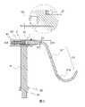
圖1係本發明股骨拉鈎結構之立體示意圖。FIG. 1 is a three-dimensional schematic diagram of the femoral retractor structure of the present invention.
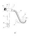
圖2係本發明股骨拉鈎結構之立體分解示意圖。FIG. 2 is a schematic exploded perspective view of the femoral retractor structure of the present invention.
圖3係本發明股骨拉鈎結構之剖面示意圖。3 is a schematic cross-sectional view of the femoral retractor structure of the present invention.
圖4係本發明鈎體為擺動狀態示意圖。FIG. 4 is a schematic diagram of the hook body of the present invention in a swinging state.
圖5係本發明鈎體為固定狀態示意圖。Figure 5 is a schematic diagram of the hook body of the present invention in a fixed state.
圖6係本發明股骨拉鈎結構之支撐股骨立體示意圖。FIG. 6 is a three-dimensional schematic diagram of the femur supported by the femoral retractor structure of the present invention.
為了使本申請的目的、技術方案及優點更加清楚明白,以下結合附圖及實施例,對本申請進行進一步詳細說明。應當理解,此處所描述的具體實施例僅僅用以解釋本申請,並不用於限定本申請。In order to make the purpose, technical solutions and advantages of the present application more clearly understood, the present application will be described in further detail below with reference to the accompanying drawings and embodiments. It should be understood that the specific embodiments described herein are only used to explain the present application, but not to limit the present application.
煩請參閱圖1至圖3,本發明提供一種股骨拉鈎結構1,用於手術中支撐人體內之股骨,其包括有一套筒2、一鈎體3、一第一限位單元4、一固定桿5以及一固定裝置6。Please refer to FIG. 1 to FIG. 3, the present invention provides a
該套筒2包括有一第一通孔21、一第二通孔22以及一第三通孔23,該第一通孔21與該第二通孔22分別位於該套筒2之兩端面,該第三通孔23位於該套筒2之側面且鄰靠於該第一通孔21,該第一通孔21、該第二通孔22以及該第三通孔23相互導通。The
於本較佳實施例中,該第一通孔21具有一第一直徑D1以及該第二通孔22具有一第二直徑D2,該第一直徑D1大於該第二直徑D2,可使得該鈎體3只能自該第一通孔21插入,以及該固定裝置6只能自該第二通孔22插入,防止使用者組合錯誤。In this preferred embodiment, the first through
該鈎體3包括有一鈎部31、一連接部32、第二限位單元8以及一第一凹槽33,於本較佳實施例中,該第二限位單元8包括有一溝槽34以及一限位凹槽35,該連接部32之一端與該鈎部31一端相接,該第一凹槽33設置於該連接部32之另一端,該溝槽34設於該連接部32之側面,該溝槽34自該連接部32之另一端延該套筒2之一軸心方向24延伸且與該限位凹槽35相連接,該溝槽34具有一第一寬度W1以及一第一深度T1,該限位凹槽35環設於該連接部32之側面且鄰靠該鈎部31,該限位凹槽35具有一第二深度T2。The
於本較佳實施例中,該鈎部31具有一鈎身部311及圓弧部312,該鈎身部311之兩端分別與該連接部32以及圓弧部311相接,該鈎身部311與該軸心方向24連接具有一角度θ為0度到90度之間,較佳者,該角度θ為介於30度到90度之間。In this preferred embodiment, the
該第一限位單元4設置於該第三通孔23中,該第一限位單元4具有一第二寬度W2且該第一限位單元4突出於該第一通孔21內壁一距離D。The first limiting
該固定桿5之一端連接於該套筒2之側面,該固定桿5鄰靠於該第二通孔22。One end of the fixing
該固定裝置6包括有一固定旋鈕61以及一固定栓62,該固定旋鈕61具有一第二凹槽611,該固定栓62之一端連接於該第二凹槽611。The fixing
上述中,於本較佳實施例,該第一寬度W1大於等於該第二寬度W2,以及該距離D小於等於該第一深度T1,可使得當該連接部32自該軸心方向24插入該第一通孔21時,該限位凸塊4延該溝槽34移動至該限位凹槽35。In the above, in this preferred embodiment, the first width W1 is greater than or equal to the second width W2, and the distance D is less than or equal to the first depth T1, so that when the connecting
另外,該第二深度T2大於等於該第一深度T1,可使該第一限位單元4移動至該限位凹槽35後,該鈎體3以該軸心方向24為旋轉軸進行一第一旋轉位移運動91。In addition, the second depth T2 is greater than or equal to the first depth T1, so that after the first limiting
當該固定裝置6以該固定栓62自該軸心方向24插入該第二通孔22,且該固定栓62之另一端位於該第一凹槽33中,使該鈎體3位於擺動狀態(如圖4所示);當該固定栓62另一端位於該第一凹槽33,遠離該第二通孔22,且該固定旋鈕61貼靠該套筒2時,使該鈎體3位於固定狀態(如圖5所示)。When the fixing
進一步說明的是,於擺動狀態時,該鈎體3能夠以該套筒2之軸心方向24為旋轉軸,進行順時針或逆時針的方向自由旋轉,該鈎體3可活動的設計,可以即時(real-time)隨著操作位置的變化而立刻自我調節到最適當的角度,避免支撐從面接觸變成點接觸的不利狀況,而傷害肌肉撕裂或是軟組織過度損傷等現象。It is further explained that, in the swing state, the
另外,該鈎體3無完全固定時,則可保留股骨拉鈎結構1對於在操作(將股骨抬起時)時,伴隨抬升機構進行調適功能,藉由將股骨進行抬升或下降時,該鈎體3根據抬升或下降,可藉由轉動達到自我調適功能。In addition, when the
當以該固定旋鈕61進行轉動,該固定栓62以該軸心方向24,自該第一凹槽33的開口深入該第一凹槽33,直到該固定旋鈕61貼靠於該套筒2,使得該固定裝置6固定於該第一凹槽33,進而讓該鈎體3位於固定位置,成為固定狀態。When the fixing
此外,於本較佳實施例中,該固定桿5之另一端具有一端部51,該端部51可插入於一活動基座7之孔洞中,使得該股骨拉鈎結構1支撐人體內之股骨。In addition, in this preferred embodiment, the other end of the fixing
也就是說,先將該鈎部31由手術入路口進入大腿近端,由肌肉之間隙深入,藉由該第一旋轉運動91使該鈎部31轉承於近端股骨之下方貼靠,完成對於該股骨的定位,藉由該固定旋鈕61移動至貼靠該第二通孔22位置時,將該鈎體3狀態進行固定,並將該端部51插入該活動基座7之孔洞中,使得該股骨拉鈎結構支撐人體內之股骨(如圖6所示)。That is to say, the
較佳者,該固定桿5更包括有一固定環52,該固定環52設置於該固定桿5之外壁且鄰靠該端部51,該固定環52限制該固定桿5插入該活動基座7之孔洞中的深度。Preferably, the fixing
又,於上述本較佳實施例中,該第一凹槽33之內壁具有一第一螺紋331,該固定栓62之外表面具有一第二螺紋621,藉由第一螺紋331與該第二螺紋621相互結合,使得該固定裝置6與該鈎體3進行連接,以及該第二凹槽611內壁具有一第三螺紋612,藉由第二螺紋621與該第三螺紋612相互結合,使得該固定旋鈕61與該固定栓62進行連接。In addition, in the above-mentioned preferred embodiment, the inner wall of the
綜上所述,本發明的優勢為:To sum up, the advantages of the present invention are:
1.本發明之拉鈎無須區分為左側專用或右側專用,將該鈎部由一手術入路口進入大腿近端,由肌肉之間隙深入,藉由該鈎部能夠擺動,使得該鈎部轉承於近端股骨之下方貼靠,完成該股骨拉鈎結構對於該股骨的定位,無須遷就於拉鈎進行特定角度貼靠之流程,可避免傷害肌肉撕裂或是軟組織過度損傷等現象。1. The retractor of the present invention does not need to be divided into left-side special use or right-side special use. The hook part enters the proximal end of the thigh through a surgical entry port, and penetrates deep through the gap of the muscle. The hook part can swing by the hook part, so that the hook part can be rotated. Abutting under the proximal femur to complete the positioning of the femoral retractor structure to the femur, without the need to accommodate the process of attaching to the retractor at a specific angle, which can avoid injury to muscle tearing or excessive damage to soft tissue.
也就是說,於實際操作過程中,例如,本發明股骨拉勾結構搭配抬升機構時,藉由該鈎部可活動的設計,可以即時(real-time)隨著操作位置的變化而立刻自我調節到最適當的角度,避免支撐從面接觸變成點接觸的不利狀況,而傷害肌肉撕裂或是軟組織過度損傷等現象。That is to say, in the actual operation process, for example, when the femoral hook structure of the present invention is matched with the lifting mechanism, the hook portion can be movable in real-time with the change of the operating position. To the most appropriate angle, to avoid the unfavorable situation that the support changes from surface contact to point contact, and damages muscle tearing or excessive soft tissue damage.
2.當定位完成後,藉由該固定裝置將該鈎體狀態進行固定,並將該固定桿插入活動基座之孔洞中,使得該股骨拉鈎結構支撐人體內之股骨,達到避免完成定位角度之拉鈎因為外力而發生偏移。2. After the positioning is completed, the hook body is fixed by the fixing device, and the fixing rod is inserted into the hole of the movable base, so that the femoral retractor structure supports the femur in the human body to avoid completing the positioning angle. The hook is deflected due to external force.
另外,該固定裝置的好處是可以選擇固定或不固定,選擇固定是符合操作當下的需求且可以維持穩定;選擇不固定,可以及時反應受力狀況而使鈎部擺動,自我調節角度。藉由上述,讓醫生可以自行依照執行手術時之需求,進行選擇固定與否。In addition, the advantage of the fixing device is that it can be fixed or unfixed. The choice of fixing is in line with the current needs of the operation and can maintain stability; the choice of unfixed can make the hook swing and self-adjust the angle in response to the stress condition in time. Through the above, the doctor can choose whether to fix or not according to the needs of the operation.
以上實施方式僅用以說明本發明的技術方案而非限制,儘管參照較佳實施方式對本發明進行了詳細說明,本領域的普通技術人員應當理解,可以對本發明的技術方案進行修改或等同替換,而不脫離本發明技術方案的精神及範圍。The above embodiments are only used to illustrate the technical solutions of the present invention and not to limit them. Although the present invention has been described in detail with reference to the preferred embodiments, those of ordinary skill in the art should understand that the technical solutions of the present invention can be modified or equivalently replaced. without departing from the spirit and scope of the technical solutions of the present invention.
1:股骨拉鈎結構1: Femoral retractor structure
2:套筒2: Sleeve
31:鈎部31: Hook
311:鈎身部311: Hook body
312:圓弧部312: Arc part
4:第一限位單元4: The first limit unit
5:固定桿5: Fixed rod
51:端部51: End
52:固定環52: Fixed ring
61:固定旋鈕61: Fixed knob
Claims (15)
Translated fromChinesePriority Applications (2)
| Application Number | Priority Date | Filing Date | Title |
|---|---|---|---|
| TW110118332ATWI765716B (en) | 2021-05-20 | 2021-05-20 | Supporting hook structure for femoral surgery |
| US17/402,721US11950771B2 (en) | 2021-05-20 | 2021-08-16 | Supporting hook structure for femoral surgery |
Applications Claiming Priority (1)
| Application Number | Priority Date | Filing Date | Title |
|---|---|---|---|
| TW110118332ATWI765716B (en) | 2021-05-20 | 2021-05-20 | Supporting hook structure for femoral surgery |
Publications (2)
| Publication Number | Publication Date |
|---|---|
| TWI765716Btrue TWI765716B (en) | 2022-05-21 |
| TW202245703A TW202245703A (en) | 2022-12-01 |
Family
ID=82594483
Family Applications (1)
| Application Number | Title | Priority Date | Filing Date |
|---|---|---|---|
| TW110118332ATWI765716B (en) | 2021-05-20 | 2021-05-20 | Supporting hook structure for femoral surgery |
Country Status (2)
| Country | Link |
|---|---|
| US (1) | US11950771B2 (en) |
| TW (1) | TWI765716B (en) |
Cited By (1)
| Publication number | Priority date | Publication date | Assignee | Title |
|---|---|---|---|---|
| TWI815499B (en)* | 2022-06-14 | 2023-09-11 | 聯合骨科器材股份有限公司 | Femoral retractor |
Families Citing this family (3)
| Publication number | Priority date | Publication date | Assignee | Title |
|---|---|---|---|---|
| US20240293113A1 (en)* | 2023-03-03 | 2024-09-05 | Foot Innovations, Llc | Retractor device |
| WO2025049391A1 (en)* | 2023-08-25 | 2025-03-06 | Hamilton Surgical Instruments LLC | Instrument holder |
| CN119097267A (en)* | 2024-10-28 | 2024-12-10 | 清华大学 | Laparoscopic telescopic device |
Citations (5)
| Publication number | Priority date | Publication date | Assignee | Title |
|---|---|---|---|---|
| CN102834073A (en)* | 2010-01-22 | 2012-12-19 | R·托马斯·哥罗兹 | Elastic knee implant and method |
| US8728088B2 (en)* | 2011-09-16 | 2014-05-20 | Smith & Nephew, Inc. | Flexible depth probe |
| TWI530271B (en)* | 2015-09-01 | 2016-04-21 | Support device for femoral head | |
| CN206587026U (en)* | 2016-08-23 | 2017-10-27 | 江苏奥康尼医疗科技发展有限公司 | A kind of near end of thighbone bone plate |
| US9826982B2 (en)* | 2007-03-13 | 2017-11-28 | Biomet Manufacturing, Llc | Distal femoral cutting guide |
Family Cites Families (26)
| Publication number | Priority date | Publication date | Assignee | Title |
|---|---|---|---|---|
| US569839A (en)* | 1896-10-20 | John t | ||
| US3749088A (en)* | 1971-06-23 | 1973-07-31 | W Kohlmann | Surgical retractor device |
| GB1409052A (en)* | 1971-09-24 | 1975-10-08 | Nat Res Dev | Surgical apparatus for bone manipulation |
| US4934352A (en)* | 1982-10-22 | 1990-06-19 | Sullivan Jr Eugene M | Surgical retractor handle construction |
| US4995875A (en)* | 1988-05-27 | 1991-02-26 | Cecil Coes | Femoral elevating tool |
| US5303694A (en)* | 1993-02-09 | 1994-04-19 | Mikhail Michael W E | Method for performing hip surgery and retractor for use therein |
| US5512038A (en)* | 1993-11-15 | 1996-04-30 | O'neal; Darrell D. | Spinal retractor apparatus having a curved blade |
| US5931777A (en)* | 1998-03-11 | 1999-08-03 | Sava; Gerard A. | Tissue retractor and method for use |
| US5882298A (en)* | 1998-08-05 | 1999-03-16 | Minnesota Scientific, Inc. | Retractor assembly with connecting pin and method for removably assembling |
| US5984865A (en)* | 1998-09-15 | 1999-11-16 | Thompson Surgical Instruments, Inc. | Surgical retractor having locking interchangeable blades |
| US6368271B1 (en)* | 2000-09-01 | 2002-04-09 | Minnesota Scientific, Inc. | Method for humerus retraction |
| DE60238997D1 (en)* | 2001-09-28 | 2011-03-03 | Stephen Ritland | CHROME OR HOOKS |
| US6860850B2 (en)* | 2001-10-05 | 2005-03-01 | Boss Instruments Ltd. | Retractor blade connector head |
| US7191683B2 (en)* | 2002-10-15 | 2007-03-20 | Boss Instruments, Ltd., Inc. | Swivel retractor blade assembly |
| EP1696789A1 (en)* | 2003-10-17 | 2006-09-06 | Minnesota Scientific, Inc. | Articulated retractor blade holder |
| US20080228191A1 (en)* | 2007-03-13 | 2008-09-18 | Howmedica Osteonics Corp. | Femoral elevator |
| US8257255B2 (en)* | 2009-02-24 | 2012-09-04 | Thompson Surgical Instruments, Inc. | Surgical retractor with locking blade |
| US8360971B2 (en)* | 2009-02-24 | 2013-01-29 | Thompson Surgical Instruments, Inc. | Surgical retractor angling device |
| US8808176B2 (en)* | 2012-02-02 | 2014-08-19 | Tedan Surgical Innovations, LLC. | Surgical process for anterior hip replacement |
| US9078635B2 (en)* | 2012-02-02 | 2015-07-14 | Tedan Surgical Innovations, Llc | Anterior hip replacement retractor assembly |
| US9848862B2 (en)* | 2015-04-03 | 2017-12-26 | Tedan Surgical Innovations, LLC. | Retractor blade assembly |
| US20170231612A1 (en)* | 2016-02-15 | 2017-08-17 | Zafer Termanini | Femoral elevator device |
| US10893855B2 (en)* | 2017-03-27 | 2021-01-19 | Thompson Surgical Instruments, Inc. | Retractor system and retractor with detachable handle |
| US11622829B2 (en)* | 2018-04-12 | 2023-04-11 | Mizuho Osi | Medical table and surgical drape for use in surgical procedures |
| US20210128132A1 (en)* | 2019-11-06 | 2021-05-06 | Mitchell Klement | Orthopedic Retractor For Hip Replacement |
| US20220096128A1 (en)* | 2020-09-25 | 2022-03-31 | Nuvasive, Inc. | Iliac crest displacement device and method |
- 2021
- 2021-05-20TWTW110118332Apatent/TWI765716B/enactive
- 2021-08-16USUS17/402,721patent/US11950771B2/enactiveActive
Patent Citations (5)
| Publication number | Priority date | Publication date | Assignee | Title |
|---|---|---|---|---|
| US9826982B2 (en)* | 2007-03-13 | 2017-11-28 | Biomet Manufacturing, Llc | Distal femoral cutting guide |
| CN102834073A (en)* | 2010-01-22 | 2012-12-19 | R·托马斯·哥罗兹 | Elastic knee implant and method |
| US8728088B2 (en)* | 2011-09-16 | 2014-05-20 | Smith & Nephew, Inc. | Flexible depth probe |
| TWI530271B (en)* | 2015-09-01 | 2016-04-21 | Support device for femoral head | |
| CN206587026U (en)* | 2016-08-23 | 2017-10-27 | 江苏奥康尼医疗科技发展有限公司 | A kind of near end of thighbone bone plate |
Cited By (1)
| Publication number | Priority date | Publication date | Assignee | Title |
|---|---|---|---|---|
| TWI815499B (en)* | 2022-06-14 | 2023-09-11 | 聯合骨科器材股份有限公司 | Femoral retractor |
Also Published As
| Publication number | Publication date |
|---|---|
| TW202245703A (en) | 2022-12-01 |
| US11950771B2 (en) | 2024-04-09 |
| US20220370060A1 (en) | 2022-11-24 |
Similar Documents
| Publication | Publication Date | Title |
|---|---|---|
| TWI765716B (en) | Supporting hook structure for femoral surgery | |
| US9750491B2 (en) | Instruments for use in femoroacetabular impingement procedures | |
| US5409489A (en) | Surgical instrument for cone-shaped sub-trochanteric rotational osteotomy | |
| JP5911474B2 (en) | Guide for drilling holes in irregularly shaped bodies | |
| JP6398129B2 (en) | Reduction forceps with double 90 ° deformation over two sides | |
| US20100191340A1 (en) | Articulating humeral Head Prosthesis | |
| JP6502458B2 (en) | Kit with multiple femoral prostheses | |
| JPH11267143A (en) | Reamer system for ellipsoidal acetabulum region | |
| JP4864893B2 (en) | Surgical support for the femur | |
| CN110538007A (en) | Elbow Prosthesis | |
| CN212089852U (en) | An acetabular treatment guide | |
| CN107080617A (en) | Posterior scleral shrinks operation special equipment bag | |
| CN111631766A (en) | A retractor fixation device in robot-assisted hip replacement surgery | |
| CN111956372B (en) | Eccentric femoral stem impactor | |
| TWI815499B (en) | Femoral retractor | |
| CN206499564U (en) | A kind of Multifunctional infant supracondylar fracture of humerus aids in external fixation device | |
| CN221712355U (en) | A hip replacement surgery actuator and an orthopedic robot | |
| CN221013431U (en) | External fixing support | |
| CN219700211U (en) | A wrist joint anti-dislocation artificial prosthesis | |
| CN218391247U (en) | Femoral intertrochanteric fracture restorer | |
| CN217447871U (en) | Acetabulum exposure device in hip joint replacement | |
| CN215839232U (en) | Special acetabulum exposing draw hook for anterior approach minimally invasive hip joint replacement | |
| CN209004158U (en) | A kind of hip-joint repositioning device | |
| CN215606166U (en) | Thighbone exposing auxiliary device | |
| CN215606167U (en) | Clamping type thighbone exposing auxiliary device |