TWI765297B - Method and apparatus for attaching and detaching magnetic bar covers for nucleic acid extraction - Google Patents
Method and apparatus for attaching and detaching magnetic bar covers for nucleic acid extractionDownload PDFInfo
- Publication number
- TWI765297B TWI765297BTW109123836ATW109123836ATWI765297BTW I765297 BTWI765297 BTW I765297BTW 109123836 ATW109123836 ATW 109123836ATW 109123836 ATW109123836 ATW 109123836ATW I765297 BTWI765297 BTW I765297B
- Authority
- TW
- Taiwan
- Prior art keywords
- plate
- magnetic rod
- sleeve
- transmission plate
- retracting
- Prior art date
Links
- 150000007523nucleic acidsChemical class0.000titleclaimsabstractdescription31
- 102000039446nucleic acidsHuman genes0.000titleclaimsabstractdescription31
- 108020004707nucleic acidsProteins0.000titleclaimsabstractdescription31
- 238000000605extractionMethods0.000titleclaimsabstractdescription30
- 238000000034methodMethods0.000titleclaimsabstractdescription19
- 230000005540biological transmissionEffects0.000claimsabstractdescription92
- 238000009434installationMethods0.000claimsdescription21
- 238000006073displacement reactionMethods0.000claimsdescription7
- 230000000630rising effectEffects0.000claimsdescription4
- 239000011324beadSubstances0.000description18
- 238000003756stirringMethods0.000description11
- 238000007886magnetic bead extractionMethods0.000description3
- 238000006243chemical reactionMethods0.000description2
- 239000000203mixtureSubstances0.000description2
- 238000001179sorption measurementMethods0.000description2
- 230000001174ascending effectEffects0.000description1
- 238000005119centrifugationMethods0.000description1
- 230000005347demagnetizationEffects0.000description1
- 238000001514detection methodMethods0.000description1
- 125000000524functional groupChemical group0.000description1
- 239000007788liquidSubstances0.000description1
- 239000000463materialSubstances0.000description1
- 238000001821nucleic acid purificationMethods0.000description1
- 239000002245particleSubstances0.000description1
- 238000000926separation methodMethods0.000description1
- 238000005406washingMethods0.000description1
Images


Landscapes
- Apparatus Associated With Microorganisms And Enzymes (AREA)
Abstract
Translated fromChineseDescription
Translated fromChinese本發明係關於一種核酸萃取磁棒套之安裝和脫離方法及設備,尤指一種適用於磁珠萃取法中安裝和脫離磁棒套之設備和方法。The present invention relates to a method and equipment for installing and removing a magnetic rod cover for nucleic acid extraction, especially a device and method suitable for installing and removing a magnetic rod cover in a magnetic bead extraction method.
核酸檢測之磁珠萃取法具有極高的變通性與實用性,又可達成自動化處理,更能夠節省操作時間以及人力的需求,且自動化處理的穩定度高,可避免人為處理的疏失或失誤,故逐漸成為核酸純化技術中的主流。進一步說明,所謂磁珠萃取法是利用帶有特殊官能基的微粒(以下稱作「磁珠」)以特異性之方式吸附檢體混合液中的核酸後,搭配使用磁性控制裝置(例如磁棒)提供磁力或磁場,用以吸引並帶動前述磁珠,以利進行反應、沖洗及提取等各階段萃取核酸流程。然而,如前所述,使用磁珠法來純化核酸的最大優點就是自動化,因磁珠在磁場條件下可以發生聚集或分散,從而可徹底擺脫離心等所需的手工操作流程。The magnetic bead extraction method for nucleic acid detection has high flexibility and practicability, and can achieve automatic processing, which can save operation time and manpower requirements, and the stability of automatic processing is high, which can avoid the negligence or mistakes of human processing. Therefore, it has gradually become the mainstream in nucleic acid purification technology. To further explain, the so-called magnetic bead extraction method is to use particles with special functional groups (hereinafter referred to as "magnetic beads") to adsorb nucleic acids in the sample mixture in a specific way, and then use a magnetic control device (such as a magnetic rod). ) provides a magnetic force or a magnetic field to attract and drive the aforementioned magnetic beads, so as to facilitate the nucleic acid extraction process at various stages such as reaction, washing and extraction. However, as mentioned earlier, the biggest advantage of using magnetic beads to purify nucleic acids is automation, as magnetic beads can aggregate or disperse in the presence of a magnetic field, eliminating the need for manual procedures such as centrifugation.
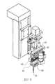
再者,於利用磁棒吸附提取磁珠的過程中,必須透過一磁棒套來隔離磁珠與磁棒,以便於後續流程中讓磁珠脫離磁棒,相關習知技術請一併參閱我國新型專利公告第M534751號「核酸萃取裝置」及圖1,圖1係習知磁棒套之安裝和脫離裝置,也援引自上開新型專利之第一圖。於該習知技術中,當欲使磁棒套(攪拌棒套91)脫離裝置時,安裝該等磁棒92之固定平台93下降並推壓導桿94,使連接於導桿94之退料板95隨之下降並下推攪拌棒套91,攪拌棒套91自轉軸96上卸下。Furthermore, in the process of using the magnetic rod to absorb and extract the magnetic beads, a magnetic rod sleeve must be used to isolate the magnetic beads and the magnetic rod, so that the magnetic beads can be separated from the magnetic rod in the subsequent process. New Patent Publication No. M534751 "Nucleic Acid Extraction Device" and Fig. 1, Fig. 1 shows the installation and disengagement device of the conventional magnetic rod sleeve, which is also quoted from the first figure of the above-mentioned new patent. In the prior art, when the magnetic rod cover (stirring rod cover 91 ) is to be disengaged from the device, the
然而,根據該先前技術所揭露的機構設計,當固定平台93去壓動導桿94而下降時,磁棒92仍然是隨著固定平台93一起下降;也就是說,磁棒92、固定平台93、導桿94以及退料板95等四者是同步下降,故當退料板95去向下推擠攪拌棒套91時,磁棒92也是同步向下移動。因此,即使退料板95可以將攪拌棒套91從轉軸96上卸下,但是一般來說磁棒92與磁棒套91是緊配合,故當磁棒92上升時,有很大的機率將使磁棒92又把攪拌棒套91帶上來而重新套上轉軸96,導致脫離失敗。However, according to the mechanism design disclosed in the prior art, when the
本發明之主要目的係在提供一種核酸萃取磁棒套之安裝和脫離方法及設備,俾能以簡單、可靠的機構,在不額外增加作動行程的情況下,可以確保磁棒套百分之百脫離設備本體。The main purpose of the present invention is to provide a method and equipment for installing and removing the nucleic acid extraction magnetic rod cover, so as to ensure that the magnetic rod cover can be 100% detached from the equipment body with a simple and reliable mechanism without additionally increasing the actuating stroke. .
為達成上述目的,本發明一種核酸萃取磁棒套之安裝和脫離方法及設備,其主要包括一傳動板、一磁棒座、一退套壓板以及一固定座;傳動板連接至於一驅動器,並受該驅動器驅動升降;磁棒座透過一第一離合構件耦接於傳動板,且磁棒座上設置有至少一磁棒;退套壓板係可選擇地透過一第二離合構件耦接於傳動板;固定座設置於磁棒座與退套壓板之間。其中,第一離合構件係常時地使磁棒座與傳動板連動,而當磁棒座受固定座之擋止時,第一離合構件係使磁棒座脫離傳動板連動;當磁棒座脫離傳動板連動後,第二離合構件係使退套壓板與傳動板連動,而當退套壓板受固定座之擋止時,退套壓板脫離傳動板連動。In order to achieve the above-mentioned purpose, a method and equipment for the installation and disengagement of a nucleic acid extraction magnetic rod sleeve of the present invention mainly include a transmission plate, a magnetic rod seat, a retracting pressure plate and a fixed seat; the transmission plate is connected to a driver, and Driven up and down by the driver; the magnet bar seat is coupled to the transmission plate through a first clutch member, and at least one magnet bar is arranged on the magnet bar seat; the retracting pressing plate is selectively coupled to the transmission plate through a second clutch member plate; the fixed seat is arranged between the magnetic rod seat and the sleeve retracting pressure plate. Wherein, the first clutch member keeps the magnet rod seat and the transmission plate in linkage, and when the magnet rod seat is stopped by the fixed seat, the first clutch member makes the magnet rod seat disengage from the transmission plate; when the magnet rod seat is disengaged After the transmission plate is interlocked, the second clutch member makes the sleeve retraction pressing plate interlock with the transmission plate, and when the retracting sleeve pressing plate is stopped by the fixed seat, the retracting sleeve pressing plate is disengaged from the transmission plate.
承上所述,本發明利用單一驅動源,亦即驅動器和傳動板之搭配,而在單一作動行程中,兩階段作動來分別完成吸附磁珠以及退套作業。進一步說明,第一階段即是透過傳動板帶動磁棒座,而使磁棒進入磁棒套,而開始吸附磁珠;而當欲退套時,亦即欲使磁棒套脫離設備時,也只是讓驅動板繼續作動,帶動退套壓板來壓退磁棒套。據此,本發明於退套作業時,退套壓板是單獨作業,而磁棒是固定不動,故可確保磁棒套可以百分之百完全脫離。Based on the above, the present invention utilizes a single driving source, that is, the combination of the driver and the transmission plate, and in a single action stroke, two stages of action are used to respectively complete the magnetic beads adsorption and sleeve retracting operations. It is further explained that the first stage is to drive the magnetic rod holder through the transmission plate, so that the magnetic rod enters the magnetic rod sleeve and starts to attract the magnetic beads; Just let the drive plate continue to act, and drive the sleeve withdrawal pressure plate to press the demagnetization rod sleeve. Accordingly, when the sleeve retracting operation of the present invention is performed, the sleeve retracting pressure plate is operated independently, and the magnetic rod is fixed, so that the magnetic rod sleeve can be 100% completely detached.
較佳的是,當傳動板帶動磁棒座下降,而磁棒座受固定座之擋止而停止下降時,第一離合構件可作動,使磁棒座脫離傳動板;又當傳動板繼續下降,且第二離合構件作動,而退套壓板受傳動板帶動下降;傳動板透過第二離合構件之作動而帶動退套壓板上升,直到當退套壓板受固定座之擋止而停止上升時,退套壓板脫離傳動板之連動;當傳動板繼續上升,而磁棒座受傳動板之帶動而上升。Preferably, when the transmission plate drives the magnetic rod holder to descend, and the magnetic rod holder is stopped by the fixed seat and stops descending, the first clutch member can be actuated to make the magnetic rod holder separate from the transmission plate; and when the transmission plate continues to descend. , and the second clutch member is actuated, and the retraction pressing plate is driven to descend by the transmission plate; the transmission plate drives the retracting pressing plate to rise through the actuation of the second clutch member, until the retracting pressing plate is stopped by the fixed seat and stops rising. The sleeve retracting plate is disconnected from the linkage of the transmission plate; when the transmission plate continues to rise, the magnetic rod seat is driven by the transmission plate to rise.
換言之,在下降行程中,本發明利用第一離合構件來使磁棒座脫離傳動板之帶動,並接續地利用第二離合構件來使退套壓板與傳動板構成連動;而在上升行程中,本發明利用第二離合構件來使退套壓板與傳動板構成帶動,直到受到固定座之擋止才脫離。In other words, in the descending stroke, the present invention uses the first clutch member to disengage the magnet rod seat from the driving of the transmission plate, and successively uses the second clutch member to form a linkage between the retracting pressure plate and the transmission plate; and in the ascending stroke, In the present invention, the second clutch member is used to drive the retracting pressing plate and the transmission plate until it is stopped by the fixed seat and then disengages.
為達成前述目的,本發明一種核酸萃取磁棒套之安裝和脫離方法,其包括以下步驟:首先,由一傳動板帶動一磁棒座作動並產生位移,使磁棒座上之至少一磁棒穿入至少一磁棒套後,磁棒座停止作動;接著,傳動板帶動一退套壓板作動並產生位移,使退套壓板促使至少一磁棒套脫離至少一磁棒;然後,傳動板接續地帶動退套壓板以及磁棒座復位。據此,本發明利用簡單、可靠機構設計,以兩段式作動來分別實現吸附磁珠以及退套作業,並可完全確保磁棒套不會再次復位,所造成的萃取失敗。In order to achieve the foregoing purpose, a method for installing and dismounting a nucleic acid extraction magnetic rod cover of the present invention includes the following steps: first, a drive plate drives a magnetic rod holder to move and generate displacement, so that at least one magnetic rod on the magnetic rod holder is displaced. After the at least one magnetic rod sleeve is penetrated, the magnetic rod seat stops moving; then, the transmission plate drives a sleeve retracting pressure plate to act and generate displacement, so that the sleeve retracting pressure plate pushes the at least one magnetic rod sleeve to separate from the at least one magnetic rod; then, the transmission plate continues The ground drives the sleeve retracting pressure plate and the magnetic rod seat to reset. Accordingly, the present invention utilizes a simple and reliable mechanism design, and realizes the adsorption of magnetic beads and the removal of the sleeve by two-stage operation, and can completely ensure that the magnetic rod sleeve will not be reset again, resulting in extraction failure.
本發明核酸萃取磁棒套之安裝和脫離方法及設備在本實施例中被詳細描述之前,要特別注意的是,以下的說明中,類似的元件將以相同的元件符號來表示。再者,本發明之圖式僅作為示意說明,其未必按比例繪製,且所有細節也未必全部呈現於圖式中。Before the detailed description of the method and equipment of the nucleic acid extraction magnetic rod sleeve of the present invention, it should be noted that in the following description, similar elements will be represented by the same element symbols. Furthermore, the drawings of the present invention are for illustrative purposes only, they are not necessarily drawn to scale, and not all of the details are shown in the drawings.
請同時參閱圖2及圖3,圖2係本發明核酸萃取磁棒套之安裝和脫離設備之立體圖,圖3係本發明核酸萃取磁棒套之安裝和脫離設備之分解圖。本實施例主要包括一驅動器2、一傳動板3、一磁棒座4、一固定座5以及一退套壓板6;其中,驅動器2安裝在一個機架上,該機架係由一安裝板21、四支撐導桿22以及固定座5所組成,四支撐導桿22架設於安裝板21和固定座5之間;而本實施例之驅動器2可為一步進馬達。Please refer to FIG. 2 and FIG. 3 at the same time, FIG. 2 is a perspective view of the installation and disengagement equipment of the nucleic acid extraction magnetic rod cover of the present invention, and FIG. 3 is an exploded view of the installation and disengagement equipment of the nucleic acid extraction magnetic rod cover of the present invention. This embodiment mainly includes a
再進一步說明,本實施例之傳動板3包括一中央螺孔32及四個導引軸套33,該四個導引軸套33分別套接於該四支撐導桿22上,並可藉由該支撐導桿22之導引升降滑移。另外,驅動器2連接一傳動螺桿23之一端,且傳動螺桿23之另一端樞接於固定座5,而傳動板3之中央螺孔32耦接於傳動螺桿23。換言之,當驅動器2驅動傳動螺桿23轉動時,傳動板3將可透過傳動螺桿23的帶動以及支撐導桿22的導引而產生升降位移。To further illustrate, the
另外,關於磁棒座4,其係類似「Ω」形狀的座體,且中央位置處開設一開孔40,而傳動螺桿23係穿過該開孔40,且磁棒座42的二側邊處則設置有多根磁棒41。再者,磁棒座4係透過第一離合構件31耦接至傳動板3,而本實施例之第一離合構件31包括二第一導引銷311及二第一彈簧312,且磁棒座4亦開設有二第一導引孔42。其中,第一導引銷311之一端係穿經磁棒座4之第一導引孔42並連接至傳動板3,而第一彈簧312係套設於第一導引銷311上,並介於第一導引銷311之另一端與磁棒座4之間。據此,第一離合構件31係隨著傳動板3升降的幅度來作動,其常時地使磁棒座4與傳動板3連動,並於特定狀態下予許磁棒座4脫離傳動板3之帶動。In addition, regarding the
再且,關於固定座5,其係設置於磁棒座4與退套壓板6之間,亦為傳動板3與退套壓板6之間;其中,固定座5係屬於前述機架之一部分,故本身並不會升降作動。另外,固定座5之下表面設置有多個磁棒套管52,而固定座5並開設有多個貫穿孔51,其貫穿固定座5之本體與磁棒套管52,並分別對應於多根磁棒41。需要說明的是,在本發明的其他實施例中,固定座5之本體內部設有傳動機構(圖中未示),其可搭配一馬達(圖中未示)來驅使磁棒套管52旋轉;而當磁棒套管52套接有磁棒套7時,磁棒套7的旋轉可做為攪拌裝置,用於攪拌磁珠混合液。Furthermore, with regard to the fixed
又,關於退套壓板6,其開設有多個通孔62,而分別對應於固定座5之磁棒套管52;且通孔62的孔徑略大於磁棒套管52的外徑,故可允許退套壓板6相對於固定座5產生升降位移,且磁棒套管52亦可於通孔62內轉動。再者,本實施例於退套壓板6與固定座5之間設有第二離合構件61,其包括四第二導引銷611及四第二彈簧612,且固定座5另外開設有四第二導引孔53。其中,第二導引銷611之一端係穿經固定座5之第二導引孔53並連接至退套壓板6之上表面,而第二彈簧612套設於第二導引銷611上,並介於第二導引銷611之另一端與固定座5之間。換言之,當傳動板3壓動第二導引銷611之頂端時,可隨即帶動退套壓板6升降。In addition, as for the
以下為本實施例之詳細運作說明,請先參閱圖4A及圖3,圖4A係本發明核酸萃取磁棒套之安裝和脫離設備於初始狀態之立體圖;在此狀態中,因磁棒41尚未插入磁棒套7,而磁棒套7可旋轉作為攪拌裝置來促進反應;亦即,馬達(圖中未示)驅動磁棒套管52旋轉,進而帶動磁棒套管52轉動攪拌。接著,當欲透過磁棒41吸取磁珠時,啟動驅動器2,進而透過傳動螺桿23驅動傳動板3開始下降。The following is a detailed operation description of this embodiment. Please refer to FIGS. 4A and 3 first. FIG. 4A is a three-dimensional view of the installation and disengagement equipment of the nucleic acid extraction magnetic rod sleeve of the present invention in the initial state; The
此時,透過第一離合構件31之第一彈簧312的彈簧張力而驅使磁棒座4同步下降,直到磁棒座4的下表面接觸固定座5的上表面時,亦即磁棒座4受固定座5之擋止時,即如圖4B所示。在此狀態時,磁棒41隨著磁棒座4下降而相對於固定座5之貫穿孔51及退套壓板6之通孔62產生軸向位移,並穿入磁棒套管52內。同樣地,當磁棒座4受固定座5之擋止時,磁棒41亦同步立即停止下降。然而,此時磁棒41的下端面也已經接觸磁棒套7的內底面,磁棒41並對混合液中磁珠形成磁吸力,來吸附磁珠。At this time, the
另一方面,當完成攪拌並完成磁珠移置的工作時,也就是欲退除磁棒套7時,傳動板3只要繼續下降,而此時因磁棒座4受固定座5之擋止而第一離合構件31開始作動,即第一導引銷311隨著傳動板3下降,而第一彈簧312則開始受到壓縮,藉而容許傳動板3脫離傳動板3而停止下降。然而,當傳動板3繼續下降後,傳動板3的下表面將接觸第二離合構件61,進而驅使第二離合構件61開始作動。On the other hand, when the stirring is completed and the magnetic bead displacement is completed, that is, when the
進言之,當傳動板3繼續下降而開始推壓第二離合構件61之第二導引銷611時,退套壓板6將隨著第二導引銷611下降,即如圖4C所示,該圖呈現退套壓板6剛開始啟動下降時,但退套壓板6的下表面尚未接觸磁棒套7,故磁棒套7仍然固定在磁棒套管52上。In other words, when the
接著,傳動板3又繼續驅動第二導引銷611下降時,而退套壓板6之下表面開始接觸磁棒套7,此時因為固定座5之磁棒套管52是固定不動,故退套壓板6在下降的過程中將會推擠套在磁棒套管52上的磁棒套7,以讓磁棒套7脫離磁棒套管52,即如圖4D所示,其係顯示磁棒套7完全脫離磁棒套管52時的情況。Then, when the
當退套完成,驅動器2啟動反轉,而傳動板3開始上升,此時因為第二離合構件61之第二彈簧612在下壓過程中壓縮蓄力,故當傳動板3上升取消下壓力時,第二彈簧612開始撐張進而帶動退套壓板6上升。另一方面,當退套壓板6上升至其上表面接觸固定座5之下表面時,此時退套壓板6受固定座5之擋止而停止上升,而第二離合構件61之第二導引銷611亦隨即脫離傳動板3。又,當傳動板3接續上升後,傳動板3之上表面接觸磁棒座4,進而帶動磁棒座4上升,直到復位至初始位置。When the unscrewing is completed, the
綜上所述,本發明利用簡單、可靠的機構配置,使用單一驅動器2,且在單一升降作動行程中可進行兩段式作業,即先讓磁棒41進入磁棒套7以吸附磁珠;並待移置磁珠後,接著即可進行退套作業,使磁棒套7脫離裝置。此外,於本發明之退套作業時,退套壓板6是單獨作業來推壓磁棒套7,而磁棒41與磁棒套管52都是固定不動,故可確保磁棒套41百分之百完全脫離,不會有無法脫離或受到磁棒41牽引而重新套上磁棒套41的情形發生。To sum up, the present invention utilizes a simple and reliable mechanism configuration, uses a
上述實施例僅係為了方便說明而舉例而已,本發明所主張之權利範圍自應以申請專利範圍所述為準,而非僅限於上述實施例。The above-mentioned embodiments are only examples for convenience of description, and the scope of the claims claimed in the present invention should be based on the scope of the patent application, rather than being limited to the above-mentioned embodiments.
2:驅動器3:傳動板4:磁棒座5:固定座6:退套壓板7:磁棒套21:安裝板22:支撐導桿23:傳動螺桿31:第一離合構件32:中央螺孔33:導引軸套40:開孔41:磁棒42:第一導引孔51:貫穿孔52:磁棒套管53:第二導引孔61:第二離合構件62:通孔311:第一導引銷312:第一彈簧611:第二導引銷612:第二彈簧2: Drive3: Transmission plate4: Magnetic Rod Holder5: Fixed seat6: Unsleeve pressure plate7: Magnetic rod cover21: Mounting plate22: Support guide rod23: Drive screw31: The first clutch member32: Central screw hole33: Guide bushing40: Opening41: Magnet42: The first pilot hole51: Through hole52: Magnetic rod casing53: Second guide hole61: Second clutch member62: Through hole311: First guide pin312: First Spring611: Second guide pin612: Second Spring
圖1係習知磁棒套之安裝和脫離裝置。圖2係本發明核酸萃取磁棒套之安裝和脫離設備之立體圖。圖3係本發明核酸萃取磁棒套之安裝和脫離設備之分解圖。圖4A係本發明核酸萃取磁棒套之安裝和脫離設備於初始狀態之立體圖。圖4B係本發明核酸萃取磁棒套之安裝和脫離設備於吸附磁珠狀態之立體圖。圖4C係本發明核酸萃取磁棒套之安裝和脫離設備於退套狀態之立體圖。圖4D係本發明核酸萃取磁棒套之安裝和脫離設備於完成退套時之立體圖。FIG. 1 shows a conventional installation and disengagement device of a magnet bar sleeve.Fig. 2 is a perspective view of the installation and disengagement equipment of the nucleic acid extraction magnetic rod sleeve of the present invention.Fig. 3 is an exploded view of the installation and disengagement equipment of the nucleic acid extraction magnetic rod cover of the present invention.FIG. 4A is a perspective view of the installation and disengagement equipment of the nucleic acid extraction magnetic rod sleeve of the present invention in an initial state.4B is a perspective view of the installation and disengagement equipment of the nucleic acid extraction magnetic rod sleeve of the present invention in the state of adsorbing magnetic beads.4C is a perspective view of the installation and disengagement equipment of the nucleic acid extraction magnetic rod sleeve of the present invention in a state of retracting the sleeve.FIG. 4D is a perspective view of the installation and disengagement equipment of the nucleic acid extraction magnetic rod cover of the present invention when the cover is completed.
2:驅動器2: Drive
3:傳動板3: Transmission plate
4:磁棒座4: Magnetic Rod Holder
5:固定座5: Fixed seat
6:退套壓板6: Unsleeve pressure plate
7:磁棒套7: Magnetic rod cover
21:安裝板21: Mounting plate
22:支撐導桿22: Support guide rod
23:傳動螺桿23: Drive screw
31:第一離合構件31: The first clutch member
33:導引軸套33: Guide bushing
41:磁棒41: Magnet
61:第二離合構件61: Second clutch member
Claims (10)
Translated fromChinesePriority Applications (1)
| Application Number | Priority Date | Filing Date | Title |
|---|---|---|---|
| TW109123836ATWI765297B (en) | 2020-07-15 | 2020-07-15 | Method and apparatus for attaching and detaching magnetic bar covers for nucleic acid extraction |
Applications Claiming Priority (1)
| Application Number | Priority Date | Filing Date | Title |
|---|---|---|---|
| TW109123836ATWI765297B (en) | 2020-07-15 | 2020-07-15 | Method and apparatus for attaching and detaching magnetic bar covers for nucleic acid extraction |
Publications (2)
| Publication Number | Publication Date |
|---|---|
| TW202204613A TW202204613A (en) | 2022-02-01 |
| TWI765297Btrue TWI765297B (en) | 2022-05-21 |
Family
ID=81323655
Family Applications (1)
| Application Number | Title | Priority Date | Filing Date |
|---|---|---|---|
| TW109123836ATWI765297B (en) | 2020-07-15 | 2020-07-15 | Method and apparatus for attaching and detaching magnetic bar covers for nucleic acid extraction |
Country Status (1)
| Country | Link |
|---|---|
| TW (1) | TWI765297B (en) |
Citations (5)
| Publication number | Priority date | Publication date | Assignee | Title |
|---|---|---|---|---|
| US20140087359A1 (en)* | 2012-09-21 | 2014-03-27 | California Institute Of Technology | Methods and devices for sample lysis |
| US20140186937A1 (en)* | 2002-04-08 | 2014-07-03 | Octane Biotech Inc. | Automated tissue engineering system |
| TWM534751U (en)* | 2016-07-12 | 2017-01-01 | 台灣圓點奈米技術股份有限公司 | Nucleic acid extractor |
| CN108291214A (en)* | 2015-09-23 | 2018-07-17 | 欧洲分子生物学实验室 | The Streptavidin of antiprotease |
| CN108424838A (en)* | 2018-05-02 | 2018-08-21 | 烟台德迈生物科技有限公司 | A kind of device extracting DNA quickly through transfer magnetic bead |
- 2020
- 2020-07-15TWTW109123836Apatent/TWI765297B/enactive
Patent Citations (5)
| Publication number | Priority date | Publication date | Assignee | Title |
|---|---|---|---|---|
| US20140186937A1 (en)* | 2002-04-08 | 2014-07-03 | Octane Biotech Inc. | Automated tissue engineering system |
| US20140087359A1 (en)* | 2012-09-21 | 2014-03-27 | California Institute Of Technology | Methods and devices for sample lysis |
| CN108291214A (en)* | 2015-09-23 | 2018-07-17 | 欧洲分子生物学实验室 | The Streptavidin of antiprotease |
| TWM534751U (en)* | 2016-07-12 | 2017-01-01 | 台灣圓點奈米技術股份有限公司 | Nucleic acid extractor |
| CN108424838A (en)* | 2018-05-02 | 2018-08-21 | 烟台德迈生物科技有限公司 | A kind of device extracting DNA quickly through transfer magnetic bead |
Also Published As
| Publication number | Publication date |
|---|---|
| TW202204613A (en) | 2022-02-01 |
Similar Documents
| Publication | Publication Date | Title |
|---|---|---|
| CN113943631A (en) | Installation and detachment method and equipment of nucleic acid extraction magnetic rod cover | |
| TWI765297B (en) | Method and apparatus for attaching and detaching magnetic bar covers for nucleic acid extraction | |
| CN214191651U (en) | Device for adsorbing and grabbing optical parts from viscous blue film | |
| CN110561095B (en) | A magnet disassembly and assembly mechanism and a magnet disassembly and assembly method | |
| CN213319884U (en) | Screen dismounting device | |
| CN219969324U (en) | Unmanned aerial vehicle wheel tear child device open | |
| CN111360885B (en) | License core positive copy separation module of self-service claim license making robot for driver license | |
| CN113526629A (en) | Sewage treatment plant with iron fillings adsorb recovery function | |
| CN2470104Y (en) | Composite sucker device for manufacturing honeycomb paper core board | |
| CN2938063Y (en) | Multi-column solid phase extraction device | |
| CN112440547A (en) | Sticker peeling device | |
| CN113172796B (en) | Suction pad and cover peeling machine | |
| CN113982506B (en) | A small repair sucker rod elevator of a rotary flange card core and its use method | |
| CN114799862B (en) | Automatic assembly device for coupling diaphragm | |
| TWI728799B (en) | Magnet split fixture | |
| CN112607684A (en) | Bottle plug dismounting device for recycling medical medicine bottles | |
| CN209556477U (en) | A kind of vehicle-carrying plate convenient for fixed vehicle | |
| CN113697488A (en) | Carousel formula integrated circuit chip handling device | |
| CN222655420U (en) | Fixed PCB product tool of accuse deep-processing | |
| CN219936894U (en) | A switch plate spring assembly machine | |
| CN216072980U (en) | Tire lifter | |
| CN114851787B (en) | Quick tire removing device for automobile tire | |
| CN222647922U (en) | Magnetic bar device for plasmid purification | |
| CN222777710U (en) | Catalyst recovery device | |
| CN218965558U (en) | Tire rubber perforating device |