TWI765268B - Back plate and method for fluidic assembly - Google Patents
Back plate and method for fluidic assemblyDownload PDFInfo
- Publication number
- TWI765268B TWI765268BTW109117560ATW109117560ATWI765268BTW I765268 BTWI765268 BTW I765268BTW 109117560 ATW109117560 ATW 109117560ATW 109117560 ATW109117560 ATW 109117560ATW I765268 BTWI765268 BTW I765268B
- Authority
- TW
- Taiwan
- Prior art keywords
- micro light
- emitting elements
- container
- grooves
- retaining wall
- Prior art date
Links
Images


Classifications
- H—ELECTRICITY
- H01—ELECTRIC ELEMENTS
- H01L—SEMICONDUCTOR DEVICES NOT COVERED BY CLASS H10
- H01L21/00—Processes or apparatus adapted for the manufacture or treatment of semiconductor or solid state devices or of parts thereof
- H01L21/67—Apparatus specially adapted for handling semiconductor or electric solid state devices during manufacture or treatment thereof; Apparatus specially adapted for handling wafers during manufacture or treatment of semiconductor or electric solid state devices or components ; Apparatus not specifically provided for elsewhere
- H01L21/67005—Apparatus not specifically provided for elsewhere
- H01L21/67011—Apparatus for manufacture or treatment
- H01L21/67144—Apparatus for mounting on conductive members, e.g. leadframes or conductors on insulating substrates
- H—ELECTRICITY
- H10—SEMICONDUCTOR DEVICES; ELECTRIC SOLID-STATE DEVICES NOT OTHERWISE PROVIDED FOR
- H10H—INORGANIC LIGHT-EMITTING SEMICONDUCTOR DEVICES HAVING POTENTIAL BARRIERS
- H10H20/00—Individual inorganic light-emitting semiconductor devices having potential barriers, e.g. light-emitting diodes [LED]
- H10H20/01—Manufacture or treatment
- H—ELECTRICITY
- H01—ELECTRIC ELEMENTS
- H01L—SEMICONDUCTOR DEVICES NOT COVERED BY CLASS H10
- H01L25/00—Assemblies consisting of a plurality of semiconductor or other solid state devices
- H01L25/03—Assemblies consisting of a plurality of semiconductor or other solid state devices all the devices being of a type provided for in a single subclass of subclasses H10B, H10D, H10F, H10H, H10K or H10N, e.g. assemblies of rectifier diodes
- H01L25/04—Assemblies consisting of a plurality of semiconductor or other solid state devices all the devices being of a type provided for in a single subclass of subclasses H10B, H10D, H10F, H10H, H10K or H10N, e.g. assemblies of rectifier diodes the devices not having separate containers
- H01L25/075—Assemblies consisting of a plurality of semiconductor or other solid state devices all the devices being of a type provided for in a single subclass of subclasses H10B, H10D, H10F, H10H, H10K or H10N, e.g. assemblies of rectifier diodes the devices not having separate containers the devices being of a type provided for in group H10H20/00
- H01L25/0753—Assemblies consisting of a plurality of semiconductor or other solid state devices all the devices being of a type provided for in a single subclass of subclasses H10B, H10D, H10F, H10H, H10K or H10N, e.g. assemblies of rectifier diodes the devices not having separate containers the devices being of a type provided for in group H10H20/00 the devices being arranged next to each other
- H—ELECTRICITY
- H10—SEMICONDUCTOR DEVICES; ELECTRIC SOLID-STATE DEVICES NOT OTHERWISE PROVIDED FOR
- H10H—INORGANIC LIGHT-EMITTING SEMICONDUCTOR DEVICES HAVING POTENTIAL BARRIERS
- H10H29/00—Integrated devices, or assemblies of multiple devices, comprising at least one light-emitting semiconductor element covered by group H10H20/00
- H10H29/10—Integrated devices comprising at least one light-emitting semiconductor component covered by group H10H20/00
- H10H29/14—Integrated devices comprising at least one light-emitting semiconductor component covered by group H10H20/00 comprising multiple light-emitting semiconductor components
- H10H29/142—Two-dimensional arrangements, e.g. asymmetric LED layout
- H—ELECTRICITY
- H01—ELECTRIC ELEMENTS
- H01L—SEMICONDUCTOR DEVICES NOT COVERED BY CLASS H10
- H01L2224/00—Indexing scheme for arrangements for connecting or disconnecting semiconductor or solid-state bodies and methods related thereto as covered by H01L24/00
- H01L2224/93—Batch processes
- H01L2224/95—Batch processes at chip-level, i.e. with connecting carried out on a plurality of singulated devices, i.e. on diced chips
- H01L2224/951—Supplying the plurality of semiconductor or solid-state bodies
- H01L2224/95101—Supplying the plurality of semiconductor or solid-state bodies in a liquid medium
- H—ELECTRICITY
- H01—ELECTRIC ELEMENTS
- H01L—SEMICONDUCTOR DEVICES NOT COVERED BY CLASS H10
- H01L25/00—Assemblies consisting of a plurality of semiconductor or other solid state devices
- H01L25/16—Assemblies consisting of a plurality of semiconductor or other solid state devices the devices being of types provided for in two or more different subclasses of H10B, H10D, H10F, H10H, H10K or H10N, e.g. forming hybrid circuits
- H01L25/167—Assemblies consisting of a plurality of semiconductor or other solid state devices the devices being of types provided for in two or more different subclasses of H10B, H10D, H10F, H10H, H10K or H10N, e.g. forming hybrid circuits comprising optoelectronic devices, e.g. LED, photodiodes
- H—ELECTRICITY
- H10—SEMICONDUCTOR DEVICES; ELECTRIC SOLID-STATE DEVICES NOT OTHERWISE PROVIDED FOR
- H10H—INORGANIC LIGHT-EMITTING SEMICONDUCTOR DEVICES HAVING POTENTIAL BARRIERS
- H10H20/00—Individual inorganic light-emitting semiconductor devices having potential barriers, e.g. light-emitting diodes [LED]
- H10H20/01—Manufacture or treatment
- H10H20/036—Manufacture or treatment of packages
- H10H20/0364—Manufacture or treatment of packages of interconnections
Landscapes
- Engineering & Computer Science (AREA)
- Power Engineering (AREA)
- Microelectronics & Electronic Packaging (AREA)
- Physics & Mathematics (AREA)
- Condensed Matter Physics & Semiconductors (AREA)
- General Physics & Mathematics (AREA)
- Computer Hardware Design (AREA)
- Manufacturing & Machinery (AREA)
- Electroluminescent Light Sources (AREA)
- Led Device Packages (AREA)
Abstract
Description
Translated fromChinese本發明涉及半導體組裝技術領域,尤其涉及一種背板及流體組裝的方法。The present invention relates to the technical field of semiconductor assembly, and in particular, to a backplane and a fluid assembly method.
流體組裝的方法為一種微小元件(如,發光二極管晶粒)的組裝方法。該方法藉由將一具有複數凹槽的基板置於具有微型發光元件的溶液中,利用液體的流動帶動微型發光元件移動,進而使微型發光元件掉落至背板的凹槽中。The method of fluid assembly is an assembly method of tiny components (eg, LED chips). In the method, a substrate with a plurality of grooves is placed in a solution with micro-light-emitting elements, and the flow of the liquid drives the micro-light-emitting elements to move, so that the micro-light-emitting elements fall into the grooves of the backplane.
然,習知的基板的結構及流體組裝基板的方法,存在微型發光元件掉入凹槽內的機率低、組裝時間久的問題。However, the conventional structure of the substrate and the method of fluidly assembling the substrate have the problems that the probability of the micro light-emitting element falling into the groove is low and the assembly time is long.
本發明一方面提供一種背板,用於流體組裝微型發光元件,所述背板包括:具有驅動電路的基板,所述基板的頂表面上具有用於容置所述微型發光元件的複數凹槽;以及複數擋牆,凸設於所述基板的頂表面上,每一個所述擋牆半圍繞在一個所述凹槽的周邊而形成一個開口,所述複數擋牆形成的開口方向一致。One aspect of the present invention provides a backplane for fluidly assembling micro light-emitting elements, the backplane comprising: a substrate having a driving circuit, and a top surface of the substrate has a plurality of grooves for accommodating the micro light-emitting elements ;as well asA plurality of retaining walls are protruded on the top surface of the base plate, each of the retaining walls half surrounds the periphery of one of the grooves to form an opening, and the openings formed by the plurality of retaining walls are in the same direction.
本發明另一方面還提供一種流體組裝的方法,其包括以下步驟:提供上述的背板;提供一容器,所述容器的內底面具有一傾斜角,將所述背板放置於所述內底面上,使所述複數擋牆形成的開口方向與所述傾斜角的開口方向一致;提供具有複數微型發光元件的懸浮液於所述容器內;以及向所述容器內滴加液滴,使所述微型發光元件被流體輸送至所述凹槽內,其中移動至所述凹槽處的微型發光元件被半圍繞其的擋牆攔住而落入所述凹槽內。Another aspect of the present invention also provides a method for fluid assembly, comprising the following steps: providing the above-mentioned backing plate; providing a container, the inner bottom surface of the container has an inclined angle, and placing the backing plate on the inner bottom surface the opening direction formed by the plurality of retaining walls is consistent with the opening direction of the inclination angle; providing a suspension having a plurality of micro light-emitting elements in the container; and dropping droplets into the container, so that the The micro-light-emitting element is transported into the groove by the fluid, wherein the micro-light-emitting element moved to the groove is stopped by the retaining wall half surrounding it and falls into the groove.
由於該背板的凹槽的周邊設置有擋牆,使得在流體組裝的過程中,微型發光元件能有效地被擋牆攔住而落入凹槽內,提高了微型發光元件掉入凹槽內的機率,降低了組裝時間。Since the periphery of the groove of the back plate is provided with a retaining wall, in the process of fluid assembly, the micro light-emitting element can be effectively blocked by the retaining wall and fall into the groove, which improves the safety of the micro light-emitting element falling into the groove. probability, reducing the assembly time.
10:背板10: Backplane
11:基板11: Substrate
11a:頂表面11a: Top surface
12:凹槽12: Groove
14:擋牆14: Retaining Wall
142:第一擋牆部142: The first retaining wall
144:第二擋牆部144: Second retaining wall
143:擋牆的開口143: Openings in retaining walls
θ 1:夾角θ 1: included angle
H1:擋牆的高度H1: Height of retaining wall
H2:微型發光元件的高度H2: height of the micro light-emitting element
20:背板組裝裝置20: Backplane assembly device
22:容器22: Container
22a:內底面22a: inner bottom surface
222:第一出口222: The first exit
224:第二出口224: Second Exit
h1:第一高度h1: first height
h2:第二高度h2: second height
24:支架24: Bracket
242:滾珠242: Ball
θ 2:傾斜角θ 2: Inclination angle
145:傾斜角的開口145: Opening of inclination angle
26:定量管26: quantitative tube
16:微型發光元件16: Miniature light-emitting element
18:懸浮液18: Suspension
40:液滴40: Droplets
圖1為本發明一實施例的背板的俯視示意圖。FIG. 1 is a schematic top view of a backplane according to an embodiment of the present invention.
圖2為圖1沿剖面線II-II剖開的示意圖。FIG. 2 is a schematic view taken along section line II-II of FIG. 1 .
圖3為本發明一實施例提供的流體組裝的方法的流程圖。FIG. 3 is a flowchart of a fluid assembly method according to an embodiment of the present invention.
圖4為本發明一實施例提供的流體組裝的方法之步驟S2的示意圖。FIG. 4 is a schematic diagram of step S2 of the fluid assembly method according to an embodiment of the present invention.
圖5為本發明一實施例提供的流體組裝的方法之步驟S4中,向容器內注入具有複數微型發光元件的懸浮液的示意圖。5 is a schematic diagram of injecting a suspension having a plurality of micro light-emitting elements into a container in step S4 of the fluid assembly method provided by an embodiment of the present invention.
圖6為本發明一實施例提供的流體組裝的方法之步驟S4中,剛落入基板的頂表面上的微型發光元件的分佈示意圖。FIG. 6 is a schematic diagram of the distribution of the micro light-emitting elements just dropped on the top surface of the substrate in step S4 of the fluid assembly method provided by an embodiment of the present invention.
圖7為本發明一實施例提供的流體組裝的方法之步驟S4中,晃動容器後,基板的頂表面上的微型發光元件的分佈示意圖。7 is a schematic diagram of the distribution of the micro light-emitting elements on the top surface of the substrate after shaking the container in step S4 of the fluid assembly method according to an embodiment of the present invention.
圖8為本發明一實施例提供的流體組裝的方法之步驟S5中,向容器內滴加液滴的示意圖。8 is a schematic diagram of dropping droplets into a container in step S5 of the fluid assembly method provided by an embodiment of the present invention.
圖9為本發明一實施例提供的流體組裝的方法之步驟S5中,容器內的微型發光元件的移動的示意圖。FIG. 9 is a schematic diagram of the movement of the micro light-emitting element in the container in step S5 of the fluid assembly method according to an embodiment of the present invention.
圖10為本發明一實施例提供的流體組裝的方法之步驟S5中,基板上的每一凹槽均被一微型發光元件佔據後的示意圖。FIG. 10 is a schematic diagram after each groove on the substrate is occupied by a micro light-emitting element in step S5 of the fluid assembly method provided by an embodiment of the present invention.
圖11為圖10中背板的俯視圖。FIG. 11 is a top view of the back plate of FIG. 10 .
圖12為本發明一實施例提供的流體組裝的方法之步驟S5中,容器內的液體被排除後的示意圖。FIG. 12 is a schematic diagram after the liquid in the container is removed in step S5 of the fluid assembly method provided by an embodiment of the present invention.
圖13為本發明一實施例提供的流體組裝的方法之步驟S5中,移除多餘的微型發光元件的示意圖。13 is a schematic diagram of removing redundant micro light-emitting elements in step S5 of the fluid assembly method according to an embodiment of the present invention.
圖14為本發明一實施例提供的流體組裝的方法之步驟S5中,背板流體組裝完成後的示意圖。FIG. 14 is a schematic diagram of the backplane after the fluid assembly is completed in step S5 of the fluid assembly method provided by an embodiment of the present invention.
圖15為圖14沿剖面線XV-XV剖開的示意圖。FIG. 15 is a schematic view taken along section line XV-XV of FIG. 14 .
圖1為本發明一實施例的背板10的俯視示意圖。圖2為圖1沿剖面線II-II剖開的示意圖。FIG. 1 is a schematic top view of a
請結合參閱圖1與圖2,背板10包括基板11以及間隔凸設於所述基板11的頂表面11a上的複數擋牆14。基板11的頂表面11a上具有用於容置微型發光元件16的複數凹槽12。每一個所述擋牆14半圍繞在一個所述凹槽12的周邊而形成一個開口143。複數所述擋牆14的開口143方向一致。Please refer to FIG. 1 and FIG. 2 , the
於一實施例中,該微型發光元件16可以為微型發光二極管(Light Emitting Diode,LED)晶粒。凹槽12的尺寸及外形與微型發光元件16的尺寸及外形相配合。所述複數擋牆14與所述複數凹槽12為一一對應的,且任意相鄰的二所述擋牆14之間的最短距離至少大於一個所述微型發光元件16的尺寸。In one embodiment, the micro
於一實施例中,所述擋牆14包括相連接的第一擋牆部142與第二擋牆部144。所述第一擋牆部142與所述第二擋牆部144緊鄰凹槽12並相交構成所述開口143。圖2中,第一擋牆部142與第二擋牆部144相交呈V字形。擋牆14的開口143方向為V字形的開口143方向。所述擋牆14的夾角θ 1為45度至120度。In one embodiment, the
於另一實施例中,所述擋牆14亦可以為半圍繞凹槽12的其他形狀,例如,弧形。第一擋牆部142與第二擋牆部144亦可以為其他形狀,不限於規則的直邊。In another embodiment, the
於一實施例中,沿所述基板11的厚度方向,所述擋牆14的高度H1(參圖15)大於其容納的所述微型發光元件16的高度H2(參圖15)的一半,以使在流體組裝的過程中,微型發光元件16能有效地被擋牆14攔住而落入凹槽12內。In one embodiment, along the thickness direction of the
於一實施例中,所述凹槽12呈圓柱狀。任意相鄰的二所述凹槽12之間的間距不小於所述凹槽12的直徑的兩倍。由於背板10的凹槽12一側設置有擋牆14,有利於在流體組裝過程中攔住微型發光元件16,提高入洞率(即,微型發光元件16進入凹槽12的機率)及組裝時間,可以彌補凹槽12之間的間距(如,相鄰的凹槽12之間的間距超過凹槽12直徑的兩倍時)對入洞率及組裝時間的影響。In one embodiment, the
於一實施例中,基板11包括依次層疊的基底(圖未示)、驅動電路(圖未示)以及絕緣層(圖未示)。絕緣層上定義有複數暴露出驅動電路的通孔(即,凹槽12)。微型發光元件16落入絕緣層上的通孔(即,凹槽12)後與驅動電路電性連接。驅動電路用於驅動微型發光元件16發光。In one embodiment, the
圖3為本發明一實施例提供的流體組裝的方法的流程圖。該方法用於在背板10上組裝微型發光元件16,其包括以下步驟。FIG. 3 is a flowchart of a fluid assembly method according to an embodiment of the present invention. The method for assembling the micro
S1:提供如圖1與圖2所示的背板10。S1: Provide the
S2:提供一具有傾斜的內底面22a的容器22。S2: Provide a
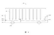
於一實施例中,步驟S2包括提供一背板組裝裝置20。如圖4所示,所述背板組裝裝置20包括支架24、位於支架24上的所述容器22以及位於容器22上方的間隔排列的複數定量管26。In one embodiment, step S2 includes providing a
如圖4所示,支架24的外底面具有複數滾珠242,使得容器22內的溶液可以被輕微晃動。定量管26位於容器22的正上方,以向容器22內提供液體或滴入液滴40以使容器22內的液體產生擾動。定量管26的管口的高度為可調節的。As shown in FIG. 4 , the outer bottom surface of the
容器22的內底面22a具有傾斜角θ 2。定義傾斜角θ 2朝向容器22的內底面22a高處的方向為傾斜角θ 2的開口方向145。於一實施例中,傾斜角θ 2小於5度。容器22的側壁具有第一出口222與第二出口224。第二出口224的高度與容器22的內底面22a齊平,第一出口222高於第二出口224。第一出口222與第二出口224用於定量或排出容器22內的液體。第一出口222與第二出口224之間的高度差定義為第一高度h1。The
S3:將所述背板10放置於所述內底面22a上,使所述複數擋牆14形成的開口143的方向與所述傾斜角θ 2的開口145的方向一致。S3: The
如圖4與圖5所示,由於容器22的內底面22a為傾斜的,使得所述背板10放置於所述容器22內後為傾斜的。其中,背板10放置於內底面22a上後,各擋牆14的開口143的方向朝向傾斜角θ 2的開口145的方向。As shown in FIGS. 4 and 5 , since the
於一實施例中,定量管26的排列間距及排列位置與基板11上的凹槽12與擋牆14的排列相配合。如圖5所示,每一個定量管26對應一個凹槽12,且每一個凹槽12的相對兩側分別設置有一個定量管26與一個擋牆14。In one embodiment, the arrangement spacing and arrangement position of the
S4:提供具有複數微型發光元件16的懸浮液18於所述容器22內。S4: Providing a
如圖5所示,利用定量管26向所述容器22內注入具有複數微型發光元件16的懸浮液18。由於每一個凹槽12對應設置有一個定量管26,使得基板11的頂表面11a上在每一個凹槽12的周圍具有複數微型發光元件16。另,由於定量管26位於每一個凹槽12的未被擋牆14圍繞的一側,使得每一所述凹槽12的未被所述擋牆14圍繞的周邊(即,擋牆14的開口143側)被注入所述懸浮液18。As shown in FIG. 5 , the
於一實施例中,先於所述容器22內注入第一高度h1的液體,若注入的液體高於第一高度h1,可藉由打開第一出口222,讓高於第一出口222的液體從第一出口222內流出,進而保持液面高度為第一高度h1,實現容器22內的液體的定量。其中,液體例如可以為醇類、酮類、鹵代烴類或水中的一種。In one embodiment, the liquid of the first height h1 is injected into the
當容器22內具有第一高度h1的液體後,利用定量管26取樣,輕輕的將具有複數微型發光元件16的懸浮液18滴入容器22內。When the
於一實施例中,步驟S4還包括將複數微型發光元件16均勻分散於溶劑內製備具有微型發光元件16的懸浮液18的步驟。其中,溶劑例如可以為醇類、酮類、鹵代烴類或水中的一種。In one embodiment, step S4 further includes the step of uniformly dispersing a plurality of micro-light-emitting
如圖6所示,剛落入基板11的頂表面11a上的微型發光元件16部分會聚集或重疊在一起。As shown in FIG. 6 , the portions of the micro
於一實施例中,步驟S4還包括利用支架24的滾珠242,晃動容器22,使容器22內的液體帶動微型發光元件16晃動,以將聚集或重疊的微型發光元件16分散開,然後靜置數分鐘,讓容器22內的液體靜止的步驟。In one embodiment, step S4 further includes using the
如圖7所示,各個微型發光元件16被晃動後,分散在凹槽12的周邊。任意相鄰的二擋牆14之間的最短距離至少大於一個微型發光元件16的尺寸。As shown in FIG. 7 , after each micro light-emitting
S5:向所述容器22內滴加液滴40,使所述微型發光元件16被流體輸送至所述背板10的凹槽12內。其中,移動至所述凹槽12處的微型發光元件16被半圍繞其的擋牆14攔住而落入所述凹槽12內。S5 : dropping
如圖8所示,調整定量管26的管口的高度,使定量管26的管口保持高出液面(亦即,高出第一出口222)。定義定量管26的管口高出液面(亦即,高出第一出口222)的高度為第二高度h2。然後,啟動定量管26,並調整液體的流量與流速,使液體在管口處形成液滴40,再以液滴40落至容器22內的液面形成流層,進而擾動位於基板11的頂表面11a上的微型發光元件16。As shown in FIG. 8, the height of the orifice of the
由於定量管26位於每一個凹槽12的未被擋牆14圍繞的一側,使得每一所述凹槽12的未被所述擋牆14圍繞的周邊(即,擋牆14的開口143側)被滴加所述液滴40。液滴40例如可以為醇類、酮類、鹵代烴類或水中的一種。Since the
如圖9所示,由於容器22的內底面22a為傾斜的,使得基板11放入其上後,基板11的相對兩端具有高度差,故容器22內的液體的流動產生方向性。即,容器22內的液體傾向於由基板11較高的一端向基板11較低的一端流動。而容器22內的液體的流動可帶動微型發光元件16流動,使得容器22內的微型發光元件16受流層的帶動以及高度差的影響,更傾向於向低於其的凹槽12的方向前進,進而提高了微型發光元件16進入凹槽12內的機率。另,由於液滴40的重力影響,增加了微型發光元件16的移動速率,進而降低了流體組裝的時間。As shown in FIG. 9 , since the
另,由於擋牆14可以有效地攔住到達凹槽12的槽口的微型發光元件16,使得微型發光元件16可以停留在凹槽12的槽口處而直接佔據凹槽12,進一步地增加了微型發光元件16進入凹槽12內的機率,降低了流體組裝的時間。In addition, since the retaining
於一實施例中,重複步驟S5,直至基板11上的每一凹槽12均被一微型發光元件16佔據。In one embodiment, step S5 is repeated until each
如圖10所示,部分微型發光元件16落入凹槽12,部分微型發光元件16仍停留在基板11的頂表面11a上。As shown in FIG. 10 , some of the micro
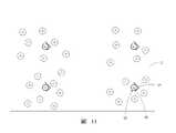
圖11為圖10中背板10的俯視圖。如圖11所示,每一凹槽12被落入其的一個微型發光元件16佔據。背板10上所有的凹槽12均被微型發光元件16佔據後,基板11的頂表面11a上仍有多餘的微型發光元件16。FIG. 11 is a top view of the
於一實施例中,所述流體組裝的方法還包括去除並收集多餘的微型發光元件16的步驟。In one embodiment, the method of fluid assembly further includes the step of removing and collecting excess micro light-emitting
如圖12所示,每一所述凹槽12被所述微型發光元件16佔據後,打開第二出口224,使容器22內的液體由第二出口224慢慢流出。As shown in FIG. 12 , after each of the
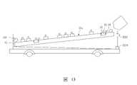
如圖13所示,將容器22內的液體排出後,將所述背板10向反方向傾斜(即,將背板10較低的一端提起)。利用液體沖洗所述基板11的頂表面11a,以移除多餘的微型發光元件16至一收集槽(圖未示)中。其中,凹槽12內的微型發光元件16由於擋牆14的保護不會被沖走。As shown in FIG. 13 , after the liquid in the
由於背板10的凹槽12的一側設置有擋牆14,容器22的內底面22a具有一傾斜角θ 2,使得液滴40的流動具有方向性,讓微型發光元件16朝向凹槽12的方向流動,提高了微型發光元件16的入洞率,同時增加了組裝良率,降低了組裝時間。另,該流體組裝的方法,可有效地收集基板11的頂表面11a上多餘的微型發光元件16,增加微型發光元件16的使用率。且擋牆14還可以在微型發光元件16回收過程中保護凹槽12內的微型發光元件16,進而降低在回收多餘微型發光元件16的過程中液體把凹槽12內的微型發光元件16沖刷出來的機率。Since the retaining
如圖14所示,背板10流體組裝完成後,每一凹槽12內具有一個微型發光元件16。於一實施例中,背板10組裝上微型發光元件16後,可作為顯示器使用。於另一實施例中,背板10組裝上微型發光元件16後,可作為液晶顯示裝置中的背光源使用。As shown in FIG. 14 , after the fluid assembly of the
圖15為圖14沿剖面線XV-XV剖開的示意圖。如圖15所示,微型發光元件16落入凹槽12後具有超出基板11的頂表面11a的部分。其中,沿基板11的厚度方向上,擋牆14的高度H1大於微型發光元件16的高度H2的一半,以使微型發光元件16在落入凹槽12過程中,有效地被擋牆14所攔住。FIG. 15 is a schematic view taken along section line XV-XV of FIG. 14 . As shown in FIG. 15 , the micro light-emitting
以上實施方式僅用以說明本發明的技術方案而非限制,儘管參照較佳實施方式對本發明進行了詳細說明,本領域的普通技術人員應當理解,可以對本發明的技術方案進行修改或等同替換,而不脫離本發明技術方案的精神及範圍。The above embodiments are only used to illustrate the technical solutions of the present invention and not to limit them. Although the present invention has been described in detail with reference to the preferred embodiments, those of ordinary skill in the art should understand that the technical solutions of the present invention can be modified or equivalently replaced. without departing from the spirit and scope of the technical solutions of the present invention.
11:基板11: Substrate
12:凹槽12: Groove
14:擋牆14: Retaining Wall
22:容器22: Container
16:微型發光元件16: Miniature light-emitting element
40:液滴40: Droplets
Claims (9)
Translated fromChineseApplications Claiming Priority (2)
| Application Number | Priority Date | Filing Date | Title |
|---|---|---|---|
| CN202010414603.1 | 2020-05-15 | ||
| CN202010414603.1ACN113675108B (en) | 2020-05-15 | 2020-05-15 | Backplane and fluid assembly method |
Publications (2)
| Publication Number | Publication Date |
|---|---|
| TW202145618A TW202145618A (en) | 2021-12-01 |
| TWI765268Btrue TWI765268B (en) | 2022-05-21 |
Family
ID=78511859
Family Applications (1)
| Application Number | Title | Priority Date | Filing Date |
|---|---|---|---|
| TW109117560ATWI765268B (en) | 2020-05-15 | 2020-05-26 | Back plate and method for fluidic assembly |
Country Status (3)
| Country | Link |
|---|---|
| US (2) | US11205738B2 (en) |
| CN (1) | CN113675108B (en) |
| TW (1) | TWI765268B (en) |
Families Citing this family (1)
| Publication number | Priority date | Publication date | Assignee | Title |
|---|---|---|---|---|
| US11764095B2 (en) | 2020-07-10 | 2023-09-19 | Samsung Electronics Co., Ltd. | Wet alignment method for micro-semiconductor chip and display transfer structure |
Citations (6)
| Publication number | Priority date | Publication date | Assignee | Title |
|---|---|---|---|---|
| US20160380158A1 (en)* | 2015-06-24 | 2016-12-29 | Sharp Laboratories Of America, Inc. | Light emitting device and fluidic manufacture thereof |
| US20170133558A1 (en)* | 2014-10-31 | 2017-05-11 | eLux Inc. | System and Method for the Fluidic Assembly of Emissive Displays |
| US20170372927A1 (en)* | 2016-06-23 | 2017-12-28 | Sharp Laboratories Of America, Inc. | Diodes offering asymmetric stability during fluidic assembly |
| TW201826491A (en)* | 2016-09-15 | 2018-07-16 | 美商伊樂視有限公司 | Display with surface mount light-emitting elements |
| US20180309023A1 (en)* | 2016-07-27 | 2018-10-25 | eLux Inc. | Substrate with Topological Features for Steering Fluidic Assembly LED Disks |
| CN110061106A (en)* | 2019-04-24 | 2019-07-26 | 京东方科技集团股份有限公司 | Chip, target base plate, manufacturing method, chip transfer method and display device |
Family Cites Families (6)
| Publication number | Priority date | Publication date | Assignee | Title |
|---|---|---|---|---|
| US6864570B2 (en)* | 1993-12-17 | 2005-03-08 | The Regents Of The University Of California | Method and apparatus for fabricating self-assembling microstructures |
| US7232704B2 (en)* | 2004-03-24 | 2007-06-19 | Matsushita Electric Industrial Co., Ltd. | Semiconductor device assembly method and semiconductor device assembly apparatus |
| US10543486B2 (en)* | 2014-10-31 | 2020-01-28 | eLux Inc. | Microperturbation assembly system and method |
| CN107833525B (en)* | 2016-09-15 | 2020-10-27 | 伊乐视有限公司 | Systems and Methods for Fluid Assembly of Light Emitting Displays |
| US10361337B2 (en)* | 2017-08-18 | 2019-07-23 | Intel Corporation | Micro light-emitting diode (LED) display and fluidic self-assembly of same |
| CN210063889U (en)* | 2019-04-26 | 2020-02-14 | 玮锋科技股份有限公司 | Packing winding tape with retaining wall structure |
- 2020
- 2020-05-15CNCN202010414603.1Apatent/CN113675108B/enactiveActive
- 2020-05-26TWTW109117560Apatent/TWI765268B/enactive
- 2020-06-29USUS16/916,011patent/US11205738B2/enactiveActive
- 2021
- 2021-11-15USUS17/526,333patent/US11569412B2/enactiveActive
Patent Citations (6)
| Publication number | Priority date | Publication date | Assignee | Title |
|---|---|---|---|---|
| US20170133558A1 (en)* | 2014-10-31 | 2017-05-11 | eLux Inc. | System and Method for the Fluidic Assembly of Emissive Displays |
| US20160380158A1 (en)* | 2015-06-24 | 2016-12-29 | Sharp Laboratories Of America, Inc. | Light emitting device and fluidic manufacture thereof |
| US20170372927A1 (en)* | 2016-06-23 | 2017-12-28 | Sharp Laboratories Of America, Inc. | Diodes offering asymmetric stability during fluidic assembly |
| US20180309023A1 (en)* | 2016-07-27 | 2018-10-25 | eLux Inc. | Substrate with Topological Features for Steering Fluidic Assembly LED Disks |
| TW201826491A (en)* | 2016-09-15 | 2018-07-16 | 美商伊樂視有限公司 | Display with surface mount light-emitting elements |
| CN110061106A (en)* | 2019-04-24 | 2019-07-26 | 京东方科技集团股份有限公司 | Chip, target base plate, manufacturing method, chip transfer method and display device |
Also Published As
| Publication number | Publication date |
|---|---|
| US11205738B2 (en) | 2021-12-21 |
| CN113675108B (en) | 2024-03-29 |
| US20210359153A1 (en) | 2021-11-18 |
| US20220077345A1 (en) | 2022-03-10 |
| US11569412B2 (en) | 2023-01-31 |
| CN113675108A (en) | 2021-11-19 |
| TW202145618A (en) | 2021-12-01 |
Similar Documents
| Publication | Publication Date | Title |
|---|---|---|
| US8216390B2 (en) | Cleaning and drying-preventing method, and cleaning and drying-preventing apparatus | |
| JP5536009B2 (en) | Substrate processing equipment | |
| TW202015122A (en) | Substrate treatment method and substrate treatment device | |
| TWI765268B (en) | Back plate and method for fluidic assembly | |
| CN102412134B (en) | Substrate processing device | |
| KR20120026628A (en) | Method for cleaning substrate | |
| KR101817212B1 (en) | Chemical nozzle and apparatus for treating substrate | |
| US20070227563A1 (en) | Cleaning apparatus and cleaning method | |
| CN102092955B (en) | Etching apparatus | |
| TWI226670B (en) | Method for arraying tiny particles through liquid, tiny particles arraying device, and semiconductor device | |
| CN100439991C (en) | Glass attachment structure for dispenser benches | |
| KR100384460B1 (en) | Apparatus for etching wafer back side | |
| CN110239221A (en) | An inkjet printing device | |
| JP5844104B2 (en) | Slit nozzle and substrate processing apparatus | |
| KR101884852B1 (en) | Chemical nozzle and apparatus for treating substrate | |
| KR102284414B1 (en) | Falling film defoamer | |
| JPH03266431A (en) | Cleaning device of substrate | |
| KR102724389B1 (en) | Bowl for Processing a Substrate and Processing Substrate Device Comprising It | |
| US20030079679A1 (en) | Spin coater | |
| KR102735906B1 (en) | Apparatus for treating substrate | |
| CN219393340U (en) | Cleaning and stripping device and cleaning and stripping system | |
| CN1042496C (en) | Liquid distributors for substance and/or heat exchange columns | |
| JPH06196466A (en) | Wafer cleaning device | |
| JP3247322B2 (en) | Cleaning equipment | |
| KR101391078B1 (en) | Apparatus for etching a glass substrate |