Movatterモバイル変換


[0]ホーム

URL:


TWI765197B - Head-mounted device and strap structure thereof - Google Patents

Head-mounted device and strap structure thereof
Download PDF

Info

Publication number
TWI765197B
TWI765197BTW108144809ATW108144809ATWI765197BTW I765197 BTWI765197 BTW I765197BTW 108144809 ATW108144809 ATW 108144809ATW 108144809 ATW108144809 ATW 108144809ATW I765197 BTWI765197 BTW I765197B
Authority
TW
Taiwan
Prior art keywords
strap
belt
driven gear
return spring
transmission member
Prior art date
Application number
TW108144809A
Other languages
Chinese (zh)
Other versions
TW202036093A (en
Inventor
林聖成
林瑞祥
Original Assignee
宏達國際電子股份有限公司
Priority date (The priority date is an assumption and is not a legal conclusion. Google has not performed a legal analysis and makes no representation as to the accuracy of the date listed.)
Filing date
Publication date
Application filed by 宏達國際電子股份有限公司filedCritical宏達國際電子股份有限公司
Priority to TW108144809ApriorityCriticalpatent/TWI765197B/en
Publication of TW202036093ApublicationCriticalpatent/TW202036093A/en
Application grantedgrantedCritical
Publication of TWI765197BpublicationCriticalpatent/TWI765197B/en

Links

Images

Landscapes

Abstract

A head-mounted device including a wearing part, a first strap, a second strap, an adjusting member, and a switching member. The first strap and the second strap are respectively connected to two opposite sides of the wearing part. A wearing space is defined by the first strap, the second strap, and the wearing part. A first part of the first strap and a second part of the second strap are overlapped with each other. The adjusting is adapted to be coupled to the first strap and the second strap, and configured to adjust an overlap degree of the first part and the second part, and then changes the wearing space. The switching member is disposed on the adjusting member and configured to switch the adjusting member to a coupling state or a decoupling state.

Description

Translated fromChinese
頭戴裝置及其束帶結構Head mounted device and its strap structure

本發明是有關於一種頭戴裝置,且特別是有關於一種可快速調整穿戴尺寸的頭戴裝置。The present invention relates to a head-mounted device, and in particular, to a head-mounted device that can quickly adjust the wearing size.

虛擬現實(Virtual Reality,VR)技術屬於新一代的顯示技術,主要結合電腦圖形系統和各種顯示及控制設備,進而產生出虛擬三維影像。虛擬三維影像主要是通過VR眼鏡來實現,而VR眼鏡通常會結合束帶而形成頭戴式顯示器(head-mounted display),以利於使用者穿戴。Virtual Reality (VR) technology belongs to a new generation of display technology, which mainly combines computer graphics systems and various display and control devices to generate virtual three-dimensional images. The virtual three-dimensional image is mainly realized by VR glasses, and the VR glasses are usually combined with a strap to form a head-mounted display (head-mounted display), which is convenient for users to wear.

一般而言,頭戴式顯示器的束帶需要約二十公分的可調整長度,以適用於不同使用者的頭型尺寸。當使用者配戴頭戴式顯示器後逐步收緊束帶,直到符合使用者的頭型尺寸。此外,當使用者欲脫下頭戴式顯示器時,則需解開束帶。若使用者需要微調束帶的鬆緊以及配戴位置時,此將導致冗長的調整時間。因而,如何提升頭戴式顯示器的調整效率,為當前重要的發展目標。Generally speaking, the strap of the head-mounted display needs to have an adjustable length of about 20 centimeters, so as to be suitable for the head size of different users. When the user wears the head-mounted display, gradually tighten the strap until it matches the size of the user's head. In addition, when the user wants to take off the head-mounted display, the strap needs to be unfastened. This will result in a lengthy adjustment time if the user needs to fine-tune the tension and the wearing position of the strap. Therefore, how to improve the adjustment efficiency of the head-mounted display is an important development goal at present.

本發明提供一種頭戴裝置及其束帶結構,可快速調整束帶的穿戴尺寸,以達到提升調整效率。The invention provides a head-mounted device and a strap structure thereof, which can quickly adjust the wearing size of the strap, so as to improve the adjustment efficiency.

本發明的頭戴裝置,包括配戴部、第一束帶、第二束帶、調節組件以及切換組件。第一束帶以及第二束帶分別連接在配戴部的相對兩側。第一束帶、第二束帶與配戴部定義穿戴空間,且第一束帶的第一部分與第二束帶的第二部分相互交疊。調節組件適於耦合第一束帶與第二束帶,用以調節第一部分與第二部分的交疊程度,進而改變穿戴空間。切換組件配置於調節組件,以切換調節組件為耦合狀態或脫鉤狀態,其中調節組件在耦合狀態下耦合於第一束帶以及第二束帶,以帶動第一束帶與第二束帶相對移動,且調節組件在脫鉤狀態下與第一束帶以及第二束帶脫鉤,使得第一束帶與第二束帶可相對於調節組件自由移動。The head-mounted device of the present invention includes a wearing part, a first strap, a second strap, an adjustment component and a switching component. The first strap and the second strap are respectively connected on opposite sides of the wearing part. The first belt, the second belt and the wearing part define a wearing space, and the first part of the first belt and the second part of the second belt overlap each other. The adjustment component is suitable for coupling the first strap and the second strap, so as to adjust the overlapping degree of the first part and the second part, thereby changing the wearing space. The switching component is arranged on the adjusting component to switch the adjusting component to a coupled state or a decoupling state, wherein the adjusting component is coupled to the first strap and the second strap in the coupled state to drive the first strap and the second strap to move relatively , and the adjusting assembly is disengaged from the first strap and the second strap in the unhooked state, so that the first strap and the second strap can move freely relative to the adjusting assembly.

本發明的束帶結構,包括第一束帶、第二束帶、調節組件以及切換組件。第一束帶的一第一部分與第二束帶的一第二部分相互交疊。調節組件適於耦合第一束帶與第二束帶,並用以調節第一部分與第二部分的交疊程度。切換組件配置於調節組件,以切換調節組件為耦合狀態或脫鉤狀態,其中調節組件在耦合狀態下耦合於第一束帶以及第二束帶,以帶動第一束帶與該第二束帶相對移動,且調節組件在脫鉤狀態下與第一束帶以及第二束帶脫鉤,使得第一束帶與第二束帶可相對於調節組件自由移動。The belt structure of the present invention includes a first belt, a second belt, an adjustment assembly and a switch assembly. A first portion of the first strap overlaps a second portion of the second strap. The adjusting assembly is adapted to couple the first strap and the second strap, and is used for adjusting the overlapping degree of the first part and the second part. The switch assembly is arranged on the adjustment assembly to switch the adjustment assembly to a coupled state or a decoupling state, wherein the adjustment assembly is coupled to the first strap and the second strap in the coupled state to drive the first strap to be opposite to the second strap moving, and the adjustment assembly is unhooked from the first strap and the second strap in the unhooked state, so that the first strap and the second strap can move freely relative to the adjustment assembly.

基於上述,本發明的頭戴裝置,透過調節組件逐步調節第一束帶與第二束帶的交疊程度,進而改變穿戴空間以配合使用者的頭型尺寸,此時調節組件為耦合狀態。此外,藉由切換組件可將調節組件從耦合狀態切換為脫鉤狀態。在脫鉤狀態下,調節組件與第一束帶以及第二束帶脫鉤,使得第一束帶與第二束帶可相對於調節組件自由移動,讓使用者可快速調整穿戴空間的尺寸,以達到提升調整效率。Based on the above, in the head-mounted device of the present invention, the overlapping degree of the first strap and the second strap is gradually adjusted through the adjustment assembly, thereby changing the wearing space to match the size of the user's head. At this time, the adjustment assembly is in a coupled state. In addition, the adjustment element can be switched from the coupled state to the decoupling state by means of the switching element. In the unhooked state, the adjustment assembly is disengaged from the first strap and the second strap, so that the first strap and the second strap can move freely relative to the adjustment assembly, so that the user can quickly adjust the size of the wearing space to achieve Improve adjustment efficiency.

為讓本發明的上述特徵和優點能更明顯易懂,下文特舉實施例,並配合所附圖式作詳細說明如下。In order to make the above-mentioned features and advantages of the present invention more obvious and easy to understand, the following embodiments are given and described in detail with the accompanying drawings as follows.

100、100A、100B:頭戴裝置100, 100A, 100B: Headset

110、110a、110b:配戴部110, 110a, 110b: Wearing part

120、120a、120b:顯示主體120, 120a, 120b: Display main body

130、130a、130b:第一束帶130, 130a, 130b: the first strap

131:第一部分131: Part One

132:第一齒條132: The first rack

140、140a、140b:第二束帶140, 140a, 140b: the second strap

141:第二部分141: Part Two

142:第二齒條142: Second rack

150、150a、150b:調節組件150, 150a, 150b: Adjustment components

151、151a、151b:從動齒輪151, 151a, 151b: driven gear

152:旋鈕152: Knob

153、153a、153b:傳動件153, 153a, 153b: Transmission parts

154:單向運動機構154: One-way movement mechanism

1541:棘輪1541: Ratchet

1542:棘爪1542: Pawl

155、155a、155b:殼體155, 155a, 155b: Housing

156、156a、156b:第一復位彈簧156, 156a, 156b: the first return spring

160、160a、160b:切換組件160, 160a, 160b: Switching Components

161、161a、161b:推頂件161, 161a, 161b: ejector

1611b:第二受力部1611b: The second force bearing part

162、162a:驅動件162, 162a: Driver

1621:第一受力部1621: The first force bearing part

163、163a:第二復位彈簧163, 163a: Second return spring

163b:第四復位彈簧163b: Fourth return spring

164:第三復位彈簧164: Third return spring

A:夾角A: Included angle

F:外力F: external force

S:穿戴空間S: Wearing space

AD:軸向AD: Axial

BS:斜面BS: Bevel

RD:徑向RD: Radial

E1、E2、E3、E4:彈力E1, E2, E3, E4: Elasticity

G1:第一開槽G1: The first slot

G2:第二開槽G2: Second slot

CW:順時針方向CW: Clockwise

CCW:逆時針方向CCW: counterclockwise

PH:定位孔PH: positioning hole

LH:限位孔LH: limit hole

IS:內側面IS: inner side

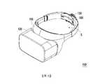
圖1A是依照本發明的一實施例的一種頭戴裝置的立體示意圖。FIG. 1A is a schematic perspective view of a head-mounted device according to an embodiment of the present invention.

圖1B是圖1A的頭戴裝置縮小穿戴空間的立體示意圖。FIG. 1B is a schematic perspective view of the head-mounted device of FIG. 1A in a reduced wearing space.

圖1C是圖1A的頭戴裝置的元件分解示意圖。FIG. 1C is an exploded schematic view of the headgear of FIG. 1A .

圖1D是圖1C的頭戴裝置的部分放大示意圖。FIG. 1D is a partially enlarged schematic view of the headgear of FIG. 1C .

圖1E是圖1C的頭戴裝置的另一角度的部分放大示意圖。1E is a partially enlarged schematic view of the headset of FIG. 1C from another angle.

圖2A是圖1A的調節組件與第一束帶、第二束帶的耦合狀態剖面示意圖。FIG. 2A is a schematic cross-sectional view of the coupling state of the adjustment assembly of FIG. 1A with the first strap and the second strap.

圖2B是圖1A的調節組件與第一束帶、第二束帶的脫鉤狀態剖面示意圖。FIG. 2B is a schematic cross-sectional view of the uncoupling state of the adjustment assembly of FIG. 1A from the first and second straps.

圖2C是圖1A的第一束帶與第二束帶的增加交疊程度示意圖。FIG. 2C is a schematic illustration of the increasing degree of overlap of the first strap and the second strap of FIG. 1A .

圖2D是圖1A的第一束帶與第二束帶的縮減交疊程度示意圖。FIG. 2D is a schematic diagram of a reduced degree of overlap of the first strap and the second strap of FIG. 1A .

圖3A是依照本發明的另一實施例的一種頭戴裝置的立體示意圖。3A is a schematic perspective view of a head-mounted device according to another embodiment of the present invention.

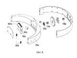
圖3B是圖3A的頭戴裝置的部分元件分解示意圖。FIG. 3B is a partially exploded schematic view of the headgear of FIG. 3A .

圖3C是圖3A的頭戴裝置的另一角度的部分元件分解示意圖。3C is a partially exploded schematic view of the headset of FIG. 3A from another angle.

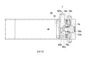
圖4A是圖3A的調節組件與第一束帶、第二束帶的耦合狀態剖面示意圖。FIG. 4A is a schematic cross-sectional view of the coupling state of the adjustment assembly of FIG. 3A with the first strap and the second strap.

圖4B是圖3A的調節組件與第一束帶、第二束帶的脫鉤狀態剖面示意圖。FIG. 4B is a schematic cross-sectional view of the uncoupling state of the adjustment assembly of FIG. 3A from the first strap and the second strap.

圖5A是依照本發明的再一實施例的一種頭戴裝置的立體示意圖。5A is a schematic perspective view of a head-mounted device according to yet another embodiment of the present invention.

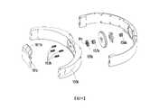
圖5B是圖5A的頭戴裝置的部分元件分解示意圖。FIG. 5B is a partially exploded schematic view of the headset of FIG. 5A .

圖5C是圖5A的頭戴裝置的另一角度的部分元件分解示意圖。FIG. 5C is a partially exploded schematic view of the headset of FIG. 5A from another angle.

圖6A是圖5A的調節組件與第一束帶、第二束帶的耦合狀態剖面示意圖。FIG. 6A is a schematic cross-sectional view of the coupling state of the adjustment assembly of FIG. 5A with the first strap and the second strap.

圖6B是圖5A的調節組件與第一束帶、第二束帶的脫鉤狀態剖面示意圖。FIG. 6B is a schematic cross-sectional view of the uncoupling state of the adjustment assembly of FIG. 5A from the first strap and the second strap.

圖1A是依照本發明的一實施例的一種頭戴裝置的立體示意圖。圖1B是圖1A的頭戴裝置縮小穿戴空間的立體示意圖。圖1C是圖1A的頭戴裝置的元件分解示意圖。圖1D是圖1C的頭戴裝置的部分放大示意圖。圖1E是圖1C的頭戴裝置的另一角度的部分放大示意圖。FIG. 1A is a schematic perspective view of a head-mounted device according to an embodiment of the present invention. FIG. 1B is a schematic perspective view of the head-mounted device of FIG. 1A in a reduced wearing space. FIG. 1C is an exploded schematic view of the headgear of FIG. 1A . FIG. 1D is a partially enlarged schematic view of the headgear of FIG. 1C . 1E is a partially enlarged schematic view of the headset of FIG. 1C from another angle.

請參考圖1A至圖1C,本實施例的頭戴裝置100,包括配戴部110、顯示主體120、第一束帶130、第二束帶140、調節組件150以及切換組件160。Referring to FIGS. 1A to 1C , the head mounteddevice 100 of this embodiment includes a wearingportion 110 , adisplay body 120 , afirst strap 130 , asecond strap 140 , anadjustment component 150 and aswitch component 160 .

配戴部110例如是塑膠、布料或其它類似的材質所製成。配戴部110內側配置有海綿或是其他材質製成的軟墊以適於接觸使用者的頭部。顯示主體120連接至配戴部110且用以輸出影像至使用者的雙眼。第一束帶130以及第二束帶140分別連接在配戴部110的相對兩側。在本實施例中,第一束帶130、第二束帶140與配戴部110例如是一體成型結構。其中,第一束帶130、第二束帶140與配戴部110定義穿戴空間S,且第一束帶130的第一部分131與第二束帶140的第二部分141相互交疊。The wearingpart 110 is made of, for example, plastic, cloth or other similar materials. The inner side of the wearingpart 110 is provided with a soft pad made of sponge or other materials so as to be suitable for contacting the user's head. The displaymain body 120 is connected to the wearingpart 110 and is used for outputting images to the eyes of the user. Thefirst strap 130 and thesecond strap 140 are respectively connected on opposite sides of the wearingpart 110 . In this embodiment, thefirst strap 130 , thesecond strap 140 and the wearingpart 110 are, for example, integrally formed structures. Thefirst strap 130 , thesecond strap 140 and the wearingportion 110 define the wearing space S, and thefirst portion 131 of thefirst strap 130 and thesecond portion 141 of thesecond strap 140 overlap each other.

圖2A是圖1A的調節組件與第一束帶、第二束帶的耦合狀態剖面示意圖。圖2B是圖1A的調節組件與第一束帶、第二束帶的脫鉤狀態剖面示意圖。圖2C是圖1A的第一束帶與第二束帶的交疊程度示意圖。FIG. 2A is a schematic cross-sectional view of the coupling state of the adjustment assembly of FIG. 1A with the first strap and the second strap. FIG. 2B is a schematic cross-sectional view of the uncoupling state of the adjustment assembly of FIG. 1A from the first and second straps. FIG. 2C is a schematic diagram of the degree of overlap of the first strap and the second strap of FIG. 1A .

請參考圖2A,調節組件150適於耦合第一束帶130與第二束帶140,用以調節第一部分131與第二部分141的交疊程度,進而改變穿戴空間S的尺寸。進一步而言,參考圖2A及圖2C,第一部分131與第二部分141的交疊程度減少代表穿戴空間S增加。反之,參考圖2B,第一部分131與第二部分141的交疊程度增加代表穿戴空間S縮小。Referring to FIG. 2A , the adjustingcomponent 150 is adapted to couple thefirst strap 130 and thesecond strap 140 to adjust the overlapping degree of thefirst part 131 and thesecond part 141 , thereby changing the size of the wearing space S. Further, referring to FIG. 2A and FIG. 2C , the decrease in the overlapping degree of thefirst part 131 and thesecond part 141 means that the wearing space S increases. On the contrary, referring to FIG. 2B , an increase in the degree of overlap between thefirst part 131 and thesecond part 141 means that the wearing space S is reduced.

請參考圖2A及圖2B,切換組件160配置於調節組件150,以切換調節組件150為耦合狀態或脫鉤狀態。其中調節組件150在耦合狀態下耦合於第一束帶130以及第二束帶140,以帶動第一束帶130與第二束帶140相對移動,用以增加或減少彼此之間的交疊程度。此外,調節組件150在脫鉤狀態下與第一束帶130以及第二束帶140脫鉤,因此調節組件150不再限制第一束帶130以及第二束帶140,使得第一束帶130與第二束帶140在外力的作用下,可相對於調節組件150自由移動,進而達到快速調整的功效。Please refer to FIG. 2A and FIG. 2B , the switchingelement 160 is disposed on the adjustingelement 150 to switch the adjustingelement 150 to a coupled state or a decoupling state. The adjustingcomponent 150 is coupled to thefirst strap 130 and thesecond strap 140 in a coupled state, so as to drive thefirst strap 130 and thesecond strap 140 to move relative to each other, so as to increase or decrease the degree of overlap between them. . In addition, theadjustment assembly 150 is disengaged from thefirst belt 130 and thesecond belt 140 in the unhooked state, so theadjustment assembly 150 no longer restricts thefirst belt 130 and thesecond belt 140, so that thefirst belt 130 and thesecond belt 140 are no longer restricted. Under the action of external force, the twostraps 140 can move freely relative to the adjustingassembly 150, thereby achieving the effect of rapid adjustment.

請配合參考圖1C及圖2C,於本實施例中,第一束帶130的第一部分131具有一第一開槽G1,第一開槽G1的一單一側形成有一第一齒條132。第二束帶140的第二部分141具有與第一開槽G1相互交疊的一第二開槽G2,第二開槽G2在相對於單一側的一對側形成有與第一齒條132平行的一第二齒條142。簡言之,第一齒條132與第二齒條142為上下平行設置。Please refer to FIG. 1C and FIG. 2C , in this embodiment, thefirst portion 131 of thefirst strap 130 has a first slot G1 , and afirst rack 132 is formed on a single side of the first slot G1 . Thesecond portion 141 of thesecond belt 140 has a second slot G2 overlapping with the first slot G1, and the second slot G2 is formed with thefirst rack 132 on a pair of sides opposite to the single side. Asecond rack 142 is parallel. In short, thefirst rack 132 and thesecond rack 142 are arranged in parallel up and down.

請配合參考圖1D及圖1E,調節組件150包括一從動齒輪151、一旋鈕152以及一傳動件153。從動齒輪151配置於第一開槽G1與第二開槽G2內並且嚙合於第一齒條132與第二齒條142,其中從動齒輪151用以帶動第一束帶130與第二束帶140相對移動以改變第一開槽G1與第二開槽G2的交疊程度。旋鈕152適於接受外力而產生轉動。傳動件153耦合從動齒輪151與旋鈕152,因此藉由轉動旋鈕152來帶動從動齒輪151旋轉。Please refer to FIG. 1D and FIG. 1E together, the adjustingassembly 150 includes a driventoothWheel 151 , aknob 152 and atransmission member 153 . The drivengear 151 is disposed in the first slot G1 and the second slot G2 and meshes with thefirst rack 132 and thesecond rack 142 , wherein the drivengear 151 is used to drive thefirst belt 130 and the second belt Thebelt 140 is moved relatively to change the degree of overlap of the first slot G1 and the second slot G2. Theknob 152 is adapted to be rotated by external force. Thetransmission member 153 is coupled to the drivengear 151 and theknob 152 , so the drivengear 151 is driven to rotate by rotating theknob 152 .

進一步而言,參考圖1B、圖2B及圖2C,當旋鈕152朝順時針方向CW旋轉時,藉由傳動件153帶動從動齒輪151朝順時針方向CW旋轉,並透過從動齒輪151連動第一齒條132與第二齒條142,使第一束帶130與第二束帶140分別朝第一方向D1與第二方向D2移動,以增加第一開槽G1與第二開槽G2的交疊程度,進而縮減穿戴空間S的尺寸(見圖1B)。1B , 2B and 2C , when theknob 152 rotates in the clockwise direction CW, the drivengear 151 is driven to rotate in the clockwise direction CW by thetransmission member 153 , and the drivengear 151 is linked with thefirst gear 151 . Arack 132 and asecond rack 142 move thefirst belt 130 and thesecond belt 140 toward the first direction D1 and the second direction D2 respectively, so as to increase the distance between the first slot G1 and the second slot G2 The degree of overlap, thereby reducing the size of the wearing space S (see FIG. 1B ).

參考圖1A、圖2A及圖2D,當旋鈕152朝逆時針方向CCW旋轉時,藉由傳動件153帶動從動齒輪151朝逆時針方向CCW旋轉,並透過從動齒輪151連動第一齒條132與第二齒條142,使第一束帶130與第二束帶140分別朝第二方向D2與第一方向D1移動,以減少第一開槽G1與第二開槽G2的交疊程度,進而增加穿戴空間S的尺寸(見圖1A)。Referring to FIGS. 1A , 2A and 2D, when theknob 152 rotates in the counterclockwise direction CCW, the drivengear 151 is driven to rotate in the counterclockwise direction CCW by thetransmission member 153 , and thefirst rack 132 is linked through the drivengear 151 With thesecond rack 142, thefirst belt 130 and thesecond belt 140 are moved toward the second direction D2 and the first direction D1 respectively, so as to reduce the degree of overlap between the first slot G1 and the second slot G2, Further, the size of the wearing space S is increased (see FIG. 1A ).

請參考圖1C至圖1E,調節組件150更包括單向運動機構154,耦合於旋鈕152,用以限制旋鈕152沿單一方向轉動,其中,單向運動機構154包括相耦合的棘輪1541與棘爪1542,分別配置於旋鈕152與一殼體155。棘爪1542用以限制棘輪1541以避免旋鈕152朝相反方向轉動。於本實施例中,單一方向例如是指順時針方向CW,故調節組件150適用於縮減穿戴空間S的尺寸。於其它實施例中,單一方向例如是指逆時針方向,而使調節組件適用於增加穿戴空間的尺寸。Please refer to FIGS. 1C to 1E , theadjustment assembly 150 further includes a one-way movement mechanism 154 coupled to theknob 152 to limit the rotation of theknob 152 in a single direction, wherein the one-way movement mechanism 154 includes a coupledratchet 1541 and apawl 1542, respectively disposed on theknob 152 and ahousing 155. Thepawl 1542 is used to limit theratchet 1541 to avoidFree knob 152 is turned in the opposite direction. In this embodiment, the single direction refers to, for example, the clockwise direction CW, so theadjustment component 150 is suitable for reducing the size of the wearing space S. In other embodiments, a single direction, for example, refers to a counterclockwise direction, so that the adjustment component is suitable for increasing the size of the wearing space.

請參考圖1D、圖1E以及圖2A,從動齒輪151包括一定位孔PH,而傳動件153的一端適於穿過定位孔PH而在定位孔PH的周向上卡掣於從動齒輪151。進一步而言,棘輪1541也包括一限位孔LH,傳動件153的另一端適於穿過限位孔LH而卡掣於棘輪1541。因此,棘輪1541適於透過傳動件153而帶動從動齒輪151。1D , FIG. 1E and FIG. 2A , the drivengear 151 includes a positioning hole PH, and one end of thetransmission member 153 is adapted to pass through the positioning hole PH and engage the drivengear 151 in the circumferential direction of the positioning hole PH. Further, theratchet wheel 1541 also includes a limiting hole LH, and the other end of thetransmission member 153 is adapted to pass through the limiting hole LH to be locked on theratchet wheel 1541 . Therefore, theratchet 1541 is suitable for driving the drivengear 151 through thetransmission member 153 .

參考圖2A及圖2B,切換組件160被設置為適於推動調節組件150的傳動件153沿定位孔PH的一軸向AD移動,以使傳動件153離開定位孔PH而脫離從動齒輪151。調節組件150更包括一第一復位彈簧156,連接傳動件153。第一復位彈簧156被設置為在其原始狀態下保持傳動件153卡掣於從動齒輪151。補充而言,第一復位彈簧156例如是壓縮彈簧,原始狀態下(即伸張狀態)推抵傳動件153穿入定位孔PH。2A and 2B , the switchingassembly 160 is adapted to push thetransmission member 153 of theadjustment assembly 150 to move along an axial direction AD of the positioning hole PH, so that thetransmission member 153 leaves the positioning hole PH and disengages from the drivengear 151 . Theadjustment assembly 150 further includes afirst return spring 156 connected to thetransmission member 153 . Thefirst return spring 156 is provided to keep thetransmission member 153 engaged with the drivengear 151 in its original state. In addition, thefirst return spring 156 is, for example, a compression spring, which pushes thetransmission member 153 into the positioning hole PH in an original state (ie, an extended state).

配合參考圖1D、圖1E、圖2A及圖2B,切換組件160包括一推頂件161、一驅動件162、一第二復位彈簧163以及第三復位彈簧164。Referring to FIG. 1D , FIG. 1E , FIG. 2A and FIG. 2B , the switchingassembly 160 includes an ejectingmember 161 , a drivingmember 162 , a second restoringspring 163 and a third restoringspring 164 .

推頂件161承靠於傳動件153,以推動傳動件153沿軸向AD移動。推頂件161被設置為適於沿定位孔PH的軸向AD移動。驅動件162承靠於推頂件161。驅動件162的第一受力部1621突出於殼體155外,驅動件162在第一受力部1621接受一外力F時驅動推頂件161移動,以推動傳動件153沿軸向AD移動。詳細而言,本實施例的驅動件162樞接於殼體155,而在接受外力F時相對於殼體155樞轉。The ejectingmember 161 is supported against thetransmission member 153 to push thetransmission member 153 to move along the axial direction AD. Theejector 161 is adapted to move along the axial direction AD of the positioning hole PH.The drivingmember 162 is supported against the ejectingmember 161 . The first force-receivingportion 1621 of the drivingmember 162 protrudes out of thehousing 155 . When the first force-receivingportion 1621 receives an external force F, the drivingmember 162 drives the ejectingmember 161 to move, so as to push thetransmission member 153 to move along the axial direction AD. In detail, the drivingmember 162 of this embodiment is pivotally connected to thecasing 155 , and pivots relative to thecasing 155 when receiving the external force F. As shown in FIG.

第二復位彈簧163例如是扭簧,連接驅動件162與殼體155,第二復位彈簧163被設置為在其原始狀態下使得傳動件153卡掣於從動齒輪151。第三復位彈簧164例如是壓縮彈簧,連接推頂件161。第三復位彈簧164被設置為在其原始狀態下使得傳動件153卡掣於從動齒輪151。簡言之,第二復位彈簧163在原始狀態下使驅動件162樞轉並相對遠離殼體155,同時,推頂件161受到第三復位彈簧164的推動而沿軸向AD朝外移動。最終,傳動件153受到第一復位彈簧156的推抵,而沿軸向AD復位並卡掣於從動齒輪151的定位孔PH。Thesecond return spring 163 is, for example, a torsion spring, which connects the drivingmember 162 and thehousing 155 . Thesecond return spring 163 is set to make thetransmission member 153 engage the drivengear 151 in its original state. Thethird return spring 164 is, for example, a compression spring, and is connected to theejector 161 . Thethird return spring 164 is provided to cause thetransmission member 153 to engage with the drivengear 151 in its original state. In short, thesecond return spring 163 pivots the drivingmember 162 relatively away from thehousing 155 in the original state, and at the same time, theejector 161 is pushed by thethird return spring 164 to move outward along the axial direction AD. Finally, thetransmission member 153 is pushed back by thefirst return spring 156 , and is reset in the axial direction AD and locked in the positioning hole PH of the drivengear 151 .

參考圖2B,當調節組件150切換為脫鉤狀態時,外力F施加於第一受力部1621並以驅動件162驅動推頂件161移動,使推頂件161推動傳動件153沿軸向AD移動,並造成傳動件153脫離於從動齒輪151的定位孔PH。因此,從動齒輪151不再受到傳動件153的限制,參考圖1A及圖1B,此時使用者適於直接拉動殼體155,以使第一束帶130與第二束帶140相對於調節組件150的殼體155自由移動,且經由從動齒輪151的旋轉以調節第一束帶130與第二束帶140的交疊程度,進而達到快速調整穿戴空間S之尺寸的功效。當調節組件150恢復耦合狀態時,只需解除外力F,並透過第一復位彈簧156、第二復位彈簧163以及第三復位彈簧164所釋放的彈力E1、E2、E3分別推動傳動件153、推頂件161以及驅動件162復歸原位(如圖2A圖所示)。Referring to FIG. 2B , when the adjustingassembly 150 is switched to the decoupling state, the external force F is applied to the first force-receivingportion 1621 and the drivingmember 162 drives the ejectingmember 161 to move, so that the ejectingmember 161 pushes thetransmission member 153 to move along the axial direction AD , and cause thetransmission member 153 to disengage from the positioning hole PH of the drivengear 151 . Therefore, the drivengear 151 is no longer restricted by thetransmission member 153. Referring to FIG. 1A and FIG. 1B, the user is suitable to directly pull thehousing 155 to adjust thefirst belt 130 and thesecond belt 140 relative to each other. Thehousing 155 of theassembly 150 is free to move, and through the rotation of the drivengear 151 to adjust the overlapping degree of thefirst strap 130 and thesecond strap 140 , so as to quickly adjust the wearing position.The effect of the size between S. When theadjustment assembly 150 returns to the coupled state, the external force F only needs to be released, and thetransmission members 153, E3 and E3 are respectively pushed through the elastic forces E1, E2 and E3 released by thefirst return spring 156, thesecond return spring 163 and thethird return spring 164. Thetop member 161 and the drivingmember 162 return to their original positions (as shown in FIG. 2A ).

在此必須說明的是,下述實施例沿用前述實施例的元件標號與部分內容,其中採用相同的標號來表示相同或近似的元件,並且省略了相同技術內容的說明。關於省略部分的說明可參考前述實施例,下述實施例不再重複贅述。It must be noted here that the following embodiments use the element numbers and part of the contents of the previous embodiments, wherein the same numbers are used to represent the same or similar elements, and the description of the same technical contents is omitted. For the description of the omitted part, reference may be made to the foregoing embodiments, and repeated descriptions in the following embodiments will not be repeated.

圖3A是依照本發明的另一實施例的一種頭戴裝置的立體示意圖。圖3B是圖3A的頭戴裝置的部分元件分解示意圖。圖3C是圖3A的頭戴裝置的另一角度的部分元件分解示意圖。圖4A是圖3A的調節組件與第一束帶、第二束帶的耦合狀態剖面示意圖。圖4B是圖3A的調節組件與第一束帶、第二束帶的脫鉤狀態剖面示意圖。3A is a schematic perspective view of a head-mounted device according to another embodiment of the present invention. FIG. 3B is a partially exploded schematic view of the headgear of FIG. 3A . 3C is a partially exploded schematic view of the headset of FIG. 3A from another angle. FIG. 4A is a schematic cross-sectional view of the coupling state of the adjustment assembly of FIG. 3A with the first strap and the second strap. FIG. 4B is a schematic cross-sectional view of the uncoupling state of the adjustment assembly of FIG. 3A from the first strap and the second strap.

請參考圖3A至圖3C、圖4A及圖4B,本實施例的頭戴裝置100A與圖1A的頭戴裝置100相近,包括配戴部110a、顯示主體120a、第一束帶130a、第二束帶140a、調節組件150a,而不同處在於,頭戴裝置100A的切換組件160a包括一推頂件161a、一驅動件162a以及至少一第二復位彈簧163a。Please refer to FIGS. 3A to 3C , 4A and 4B. The head mounteddevice 100A of this embodiment is similar to the head mounteddevice 100 of FIG. 1A , including a wearingportion 110a, a displaymain body 120a, afirst strap 130a, a second Thestrap 140a, theadjustment assembly 150a, and the difference is that the switchingassembly 160a of the head-mounteddevice 100A includes a pushingmember 161a, a drivingmember 162a and at least asecond return spring 163a.

推頂件161a承靠於傳動件153a,以推動傳動件153a沿軸向AD移動。推頂件161被設置為適於沿定位孔PH的軸向AD移動。驅動件162a滑設於殼體155a且垂直於軸向AD,而在接受外力F時驅動件162a相對於殼體155a產生沿徑向RD的移動。驅動件162a具有一斜面BS且斜面BS承靠於推頂件161a,其中斜面BS與軸向AD之間具有一非90度的夾角A。The ejectingmember 161a is supported against thetransmission member 153a to push thetransmission member 153a to move along the axial direction AD. Theejector 161 is adapted to move along the axial direction AD of the positioning hole PH. The drivingmember 162a is slidably arranged on thehousing 155a and is perpendicular to the axial direction AD, and isWhen the external force F is applied, the drivingmember 162a moves relative to thehousing 155a in the radial direction RD. The drivingmember 162a has an inclined surface BS and the inclined surface BS bears against the ejectingmember 161a, wherein there is an included angle A between the inclined surface BS and the axial direction AD which is not 90 degrees.

至少一第二復位彈簧163a包括有多個且例如是壓縮彈簧,連接驅動件162a與殼體155a,多個第二復位彈簧163a被設置為在其原始狀態下使得傳動件153a卡掣於從動齒輪151a。進一步而言,各第二復位彈簧163a的兩端沿徑向RD分別推抵驅動件162a與殼體155a,在原始狀態(即伸張狀態)下,使驅動件162a的第一受力部1621a朝上突出於殼體155a。At least onesecond return spring 163a includes a plurality of, for example, compression springs, connecting the drivingmember 162a and thehousing 155a, and the plurality of second returningsprings 163a are arranged to make thetransmission member 153a clamp the driven member in itsoriginal state gear 151a. Further, the two ends of eachsecond return spring 163a push against the drivingmember 162a and thehousing 155a respectively along the radial direction RD. It protrudes from thehousing 155a.

參考圖4A及圖4B,當調節組件150a切換為脫鉤狀態時,外力F施加於第一受力部1621a並以驅動件162a的斜面BS驅動推頂件161a移動,使推頂件161a推動傳動件153a沿軸向AD移動,並造成傳動件153a脫離於從動齒輪151a的定位孔PH。因此,從動齒輪151a不再受到傳動件153a的限制。當調節組件150a恢復耦合狀態時,只需解除外力F,並透過第一復位彈簧156a與第二復位彈簧163a所釋放的彈力E1、E2分別推動傳動件153a、推頂件161a與驅動件162a復歸原位。4A and 4B, when the adjustingassembly 150a is switched to the decoupling state, the external force F is applied to the first force-receivingportion 1621a and drives the ejectingmember 161a to move with the inclined plane BS of the drivingmember 162a, so that the ejectingmember 161a pushes thetransmission member 153a moves in the axial direction AD, and causes thetransmission member 153a to disengage from the positioning hole PH of the drivengear 151a. Therefore, the drivengear 151a is no longer restricted by thetransmission member 153a. When the adjustingassembly 150a returns to the coupled state, the external force F only needs to be released, and thetransmission member 153a, theejector member 161a and the drivingmember 162a are respectively pushed back by the elastic forces E1 and E2 released by thefirst return spring 156a and the second return spring 163a. in situ.

圖5A是依照本發明的再一實施例的一種頭戴裝置的立體示意圖。圖5B是圖5A的頭戴裝置的部分元件分解示意圖。圖5C是圖5A的頭戴裝置的另一角度的部分元件分解示意圖。圖6A是圖5A的調節組件與第一束帶、第二束帶的耦合狀態剖面示意圖。圖6B是圖5A的調節組件與第一束帶、第二束帶的脫鉤狀態剖面示意圖。5A is a schematic perspective view of a head-mounted device according to yet another embodiment of the present invention. FIG. 5B is a partially exploded schematic view of the headset of FIG. 5A . FIG. 5C is a partially exploded schematic view of the headset of FIG. 5A from another angle. FIG. 6A is a schematic cross-sectional view of the coupling state of the adjustment assembly of FIG. 5A with the first strap and the second strap. FIG. 6B is the uncoupling state of the adjustment assembly of FIG. 5A from the first and second strapsSchematic cross section.

請參考圖5A至圖5C、圖6A及圖6B,本實施例的頭戴裝置100B與圖1A的頭戴裝置100相近,包括配戴部110b、顯示主體120b、第一束帶130b、第二束帶140b以及調節組件150b。不同處在於,頭戴裝置100B的切換組件160b包括一推頂件161b以及至少一第四復位彈簧163b。Referring to FIGS. 5A to 5C , 6A and 6B, the head mounteddevice 100B of this embodiment is similar to the head mounteddevice 100 of FIG. 1A , including a wearingpart 110b, a displaymain body 120b, afirst strap 130b, asecond Strap 140b andadjustment assembly 150b. The difference is that the switching component 160b of the head-mounteddevice 100B includes a push-upmember 161b and at least afourth return spring 163b.

推頂件161b承靠於傳動件153b,以推動傳動件153b沿軸向AD移動。推頂件161b被設置為適於沿定位孔PH的軸向AD移動。推頂件161b的一第二受力部1611b突出於殼體155b外,推頂件161b在第二受力部1611b接受外力F時推動傳動件153b沿軸向移動AD。Theejector 161b is supported against thetransmission member 153b to push thetransmission member 153b to move along the axial direction AD. Theejector 161b is adapted to move along the axial direction AD of the positioning hole PH. A second force-receivingportion 1611b of the ejectingmember 161b protrudes out of thehousing 155b, and the ejectingmember 161b pushes thetransmission member 153b to move AD along the axial direction when the second force-receivingportion 1611b receives the external force F.

至少一第四復位彈簧163b包括有多個且例如是壓縮彈簧,多個第四復位彈簧163b沿軸向AD連接推頂件161b。各第四復位彈簧163b被設置為在其原始狀態下使得傳動件153b卡掣於從動齒輪151b。進一步而言,各第四復位彈簧163b的兩端沿軸向AD分別推抵推頂件161b與殼體155b的內側面IS,在原始狀態(即伸張狀態)下,使推頂件161b相對遠離殼體155b的內側面IS。At least onefourth return spring 163b includes a plurality of, for example, compression springs, and the plurality of fourth return springs 163b are connected to theejector 161b along the axial direction AD. Each of the fourth return springs 163b is provided so that thetransmission member 153b is engaged with the drivengear 151b in its original state. Further, both ends of eachfourth return spring 163b push against theejector 161b and the inner side IS of thehousing 155b along the axial direction AD, respectively, and in the original state (ie, the extended state), theejector 161b is relatively far away The inner surface IS of thecasing 155b.

參考圖6A及圖6B,當調節組件150a切換為脫鉤狀態時,外力F施加於第二受力部1611b並以推頂件161b驅動推頂件161b移動,使推頂件161b推動傳動件153b沿軸向AD移動,並造成傳動件153b脫離於從動齒輪151b的定位孔PH。因此,從動齒輪151b不再受到傳動件153b的限制。當調節組件150b恢復耦合狀態時,只需解除外力F,並透過多個第四復位彈簧163b與第一復位彈簧156b所釋放的彈力E4、E1分別推動推頂件161b與傳動件153b復歸原位。6A and 6B, when the adjustingassembly 150a is switched to the decoupling state, the external force F is applied to the second force-receivingportion 1611b and theejector 161b is driven to move by theejector 161b, so that theejector 161b pushes thetransmission member 153b along the The axial direction AD moves and causes thetransmission member 153b to disengage from the positioning hole PH of the drivengear 151b. Therefore, the drivengear 151b is no longer restricted by thetransmission member 153b. When theadjustment assembly 150b recovers the couplingIn the closed state, only the external force F needs to be released, and the ejectingmember 161b and thetransmission member 153b are respectively pushed back to their original positions by the elastic forces E4 and E1 released by the plurality of fourth return springs 163b and the first return springs 156b.

綜上所述,本發明的頭戴裝置,透過調節組件逐步調節第一束帶與第二束帶的交疊程度,進而改變穿戴空間以配合使用者的頭型尺寸,此時調節組件為耦合狀態。此外,藉由切換組件可將調節組件從耦合狀態切換為脫鉤狀態。在脫鉤狀態下,調節組件與第一束帶以及第二束帶脫鉤,使得第一束帶與第二束帶可相對於調節組件自由移動,讓使用者可快速調整穿戴空間的尺寸,以達到提升調整效率。To sum up, in the head-mounted device of the present invention, the degree of overlap between the first strap and the second strap is gradually adjusted through the adjustment component, thereby changing the wearing space to match the size of the user's head. At this time, the adjustment component is a coupling state. In addition, the adjustment element can be switched from the coupled state to the decoupling state by means of the switching element. In the unhooked state, the adjustment assembly is disengaged from the first strap and the second strap, so that the first strap and the second strap can move freely relative to the adjustment assembly, so that the user can quickly adjust the size of the wearing space to achieve Improve adjustment efficiency.

進一步而言,當調節組件從脫鉤狀態切換為耦合狀態時,只需解除所施加的外力,即可通過各個復位彈簧的彈力推抵,而使調節組件自動復歸原位,以達到提升調整效率。Further, when the adjustment assembly is switched from the uncoupling state to the coupling state, only the applied external force can be released, and the adjustment assembly can be automatically returned to its original position by the elastic force of each return spring, so as to improve the adjustment efficiency. .

雖然本發明已以實施例揭露如上,然其並非用以限定本發明,任何所屬技術領域中具有通常知識者,在不脫離本發明的精神和範圍內,當可作些許的更動與潤飾,故本發明的保護範圍當視後附的申請專利範圍所界定者為準。Although the present invention has been disclosed above by the embodiments, it is not intended to limit the present invention. Anyone with ordinary knowledge in the technical field can make some changes and modifications without departing from the spirit and scope of the present invention. Therefore, The protection scope of the present invention shall be determined by the scope of the appended patent application.

100:頭戴裝置100: Headset

110:配戴部110: Wearing Department

120:顯示主體120: Display subject

130:第一束帶130: First Girdle

140:第二束帶140: Second Girdle

150:調節組件150: Adjustment components

160:切換組件160: Toggle Components

S:穿戴空間S: Wearing space

Claims (30)

Translated fromChinese
一種頭戴裝置,包括:一配戴部;一第一束帶以及一第二束帶,分別連接在該配戴部的相對兩側,該第一束帶、該第二束帶與該配戴部定義一穿戴空間,且該第一束帶的一第一部分與該第二束帶的一第二部分相互交疊;一調節組件,適於耦合該第一束帶與該第二束帶,並用以調節該第一部分與該第二部分的一交疊程度,進而改變該穿戴空間;以及一切換組件,配置於該調節組件,以切換該調節組件為一耦合狀態或一脫鉤狀態,其中該調節組件在該耦合狀態下耦合於該第一束帶以及該第二束帶,以帶動該第一束帶與該第二束帶相對移動並逐步調節該第一束帶與該第二束帶的交疊程度,且該調節組件在該脫鉤狀態下與該第一束帶以及該第二束帶脫鉤,使得該第一束帶與該第二束帶可相對於該調節組件自由移動,其中該第一部分具有一第一開槽,該第一開槽的一單一側形成有一第一齒條,且該第二部分具有與該第一開槽相互交疊的一第二開槽,該第二開槽在相對於該單一側的一對側形成有與該第一齒條平行的一第二齒條,該調節組件包括:一從動齒輪,配置於該第一開槽與該第二開槽內並且嚙合於該第一齒條與該第二齒條,以帶動該第一束帶與該第二束帶相對移動;一旋鈕;以及一傳動件,適於耦合該從動齒輪與該旋鈕,以藉由轉動該旋鈕來帶動該從動齒輪旋轉,其中在該耦合狀態下,該傳動件耦合該從動齒輪,且在該脫鉤狀態下,該傳動件脫離該從動齒輪。A head-mounted device, comprising: a wearing part; a first strap and a second strap, respectively connected on opposite sides of the wearing part, the first strap, the second strap and the matching The wearing part defines a wearing space, and a first part of the first belt and a second part of the second belt overlap each other; an adjusting component is suitable for coupling the first belt and the second belt , and is used to adjust a degree of overlap between the first part and the second part, so as to change the wearing space; and a switch element, disposed in the adjustment element, to switch the adjustment element to a coupled state or a decoupling state, wherein The adjusting component is coupled to the first strap and the second strap in the coupled state, so as to drive the first strap and the second strap to move relative to each other and gradually adjust the first strap and the second strap the degree of overlap of the straps, and the adjustment assembly is unhooked from the first strap and the second strap in the unhooked state, so that the first strap and the second strap can move freely relative to the adjustment assembly, The first part has a first slot, a first rack is formed on a single side of the first slot, and the second part has a second slot overlapping with the first slot, the A second rack parallel to the first rack is formed on a pair of sides of the second slot relative to the single side, and the adjusting assembly includes: a driven gear disposed between the first slot and the first rack. The two slots are engaged with the first rack and the second rack, so as to drive the first belt and the second belt to move relatively;a knob; and a transmission member, suitable for coupling the driven gear and the knob, so as to drive the driven gear to rotate by rotating the knob, wherein in the coupling state, the transmission member is coupled to the driven gear, and In the uncoupling state, the transmission member is disengaged from the driven gear.如申請專利範圍第1項所述的頭戴裝置,其中該調節組件更包括一單向運動機構,耦合於該旋鈕,用以限制該旋鈕沿單一方向轉動。The head-mounted device of claim 1, wherein the adjustment component further includes a one-way movement mechanism coupled to the knob for restricting the knob from rotating in a single direction.如申請專利範圍第2項所述的頭戴裝置,其中該單向運動機構包括相耦合的一棘輪與一棘爪,分別配置於該旋鈕與一殼體。The head-mounted device as claimed in claim 2, wherein the one-way motion mechanism comprises a coupled ratchet and a pawl, which are respectively disposed on the knob and a housing.如申請專利範圍第1項所述的頭戴裝置,其中該從動齒輪包括一定位孔,而該傳動件適於穿過該定位孔而在該定位孔的一周向上卡掣於該從動齒輪。The headgear device according to claim 1, wherein the driven gear comprises a positioning hole, and the transmission member is adapted to pass through the positioning hole to engage the driven gear in a circumferential direction of the positioning hole .如申請專利範圍第4項所述的頭戴裝置,其中該切換組件被設置為適於推動該傳動件沿該定位孔的一軸向移動,以使該傳動件離開該定位孔而脫離該從動齒輪。The headgear device of claim 4, wherein the switching component is configured to push the transmission member to move along an axial direction of the positioning hole, so that the transmission member leaves the positioning hole and disengages from the slave moving gear.如申請專利範圍第5項所述的頭戴裝置,其中該調節組件更包括一第一復位彈簧,連接該傳動件,該第一復位彈簧被設置為在其原始狀態下保持該傳動件卡掣於該從動齒輪。The headgear device as claimed in claim 5, wherein the adjustment assembly further comprises a first return spring connected to the transmission member, and the first return spring is configured to keep the transmission member in its original state to be latched on the driven gear.如申請專利範圍第5項所述的頭戴裝置,其中該切換組件包括一推頂件,承靠於該傳動件,以推動該傳動件沿該軸向移動。The headgear device as claimed in claim 5, wherein the switching component comprises a pushing member, which is supported against the transmission member, so as to push the transmission member to move along the axial direction.如申請專利範圍第7項所述的頭戴裝置,其中該推頂件被設置為適於沿該定位孔的該軸向移動,且該切換組件更包括一驅動件,承靠於該推頂件,該驅動件的一第一受力部突出於一殼體外,該驅動件在該第一受力部接受一外力時驅動該推頂件移動。The head-mounted device as claimed in claim 7, wherein the ejector is configured to move along the axial direction of the positioning hole, and the switch assembly further includes a drive member that is supported against the ejector a first force-receiving part of the driving part protrudes out of a casing, and the driving part drives the ejecting part to move when the first force-receiving part receives an external force.如申請專利範圍第8項所述的頭戴裝置,其中該驅動件樞接於該殼體,而在接受該外力時相對於該殼體樞轉。The head-mounted device as claimed in claim 8, wherein the driving member is pivotally connected to the casing, and pivots relative to the casing when receiving the external force.如申請專利範圍第9項所述的頭戴裝置,其中該切換組件更包括一第二復位彈簧,連接該驅動件與該殼體,該第二復位彈簧被設置為在其原始狀態下使得該傳動件卡掣於該從動齒輪。The head-mounted device as claimed in claim 9, wherein the switch assembly further comprises a second return spring, connecting the driving member and the housing, the second return spring is set to make the The transmission element is clamped to the driven gear.申請專利範圍第8項所述的頭戴裝置,其中該驅動件滑設於該殼體,而在接受該外力時相對於該殼體移動,該驅動件具有一斜面,承靠於該推頂件。The headgear described in claim 8, wherein the driving member is slidably mounted on the housing, and moves relative to the housing when receiving the external force, the driving member has an inclined surface and is supported against the pusher pieces.如申請專利範圍第11項所述的頭戴裝置,其中該切換組件更包括一至少一第二復位彈簧,連接該驅動件與該殼體,該至少一第二復位彈簧被設置為在其原始狀態下使得該傳動件卡掣於該從動齒輪。The headgear device as claimed in claim 11, wherein the switch assembly further comprises at least one second return spring, connecting the driving member and the housing, the at least one second return spring is set at its original position In this state, the transmission element is clamped to the driven gear.如申請專利範圍第7項所述的頭戴裝置,其中該切換組件更包括一第三復位彈簧,連接該推頂件,該第三復位彈簧被設置為在其原始狀態下使得該傳動件卡掣於該從動齒輪。The headgear device as claimed in claim 7, wherein the switch assembly further comprises a third return spring connected to the ejector, and the third return spring is set to cause the transmission element to snap in its original state. to the driven gear.如申請專利範圍第7項所述的頭戴裝置,其中該推頂件的一第二受力部突出於一殼體外,該推頂件在該第二受力部接受一外力時推動該傳動件沿該軸向移動。The headgear device as claimed in claim 7, wherein a second force-receiving portion of the ejector protrudes out of a housing, and the ejector pushes the transmission when the second force-receiving portion receives an external force The piece moves along this axis.如申請專利範圍第14項所述的頭戴裝置,其中該切換組件更包括至少一第四復位彈簧,連接該推頂件,該至少一第四復位彈簧被設置為在其原始狀態下使得該傳動件卡掣於該從動齒輪。The headgear device of claim 14, wherein the switch assembly further comprises at least one fourth return spring connected to the ejector, the at least one fourth return spring is set to make the The transmission element is clamped to the driven gear.一種束帶結構,包括:一第一束帶以及一第二束帶,且該第一束帶的一第一部分與該第二束帶的一第二部分相互交疊;一調節組件,適於耦合該第一束帶與該第二束帶,並用以調節該第一部分與該第二部分的一交疊程度;以及一切換組件,配置於該調節組件,以切換該調節組件為一耦合狀態或一脫鉤狀態,其中該調節組件在該耦合狀態下耦合於該第一束帶以及該第二束帶,以帶動該第一束帶與該第二束帶相對移動並逐步調節該第一束帶與該第二束帶的交疊程度,且該調節組件在該脫鉤狀態下與該第一束帶以及該第二束帶脫鉤,使得該第一束帶與該第二束帶可相對於該調節組件自由移動,其中該第一部分具有一第一開槽,該第一開槽的一單一側形成有一第一齒條,且該第二部分具有與該第一開槽相互交疊的一第二開槽,該第二開槽在相對於該單一側的一對側形成有與該第一齒條平行的一第二齒條,該調節組件包括:一從動齒輪,配置於該第一開槽與該第二開槽內並且嚙合於該第一齒條與該第二齒條,以帶動該第一束帶與該第二束帶相對移動;一旋鈕;以及一傳動件,適於耦合該從動齒輪與該旋鈕,以藉由轉動該旋鈕來帶動該從動齒輪旋轉,其中在該耦合狀態下,該傳動件耦合該從動齒輪,且在該脫鉤狀態下,該傳動件脫離該從動齒輪。A belt structure, comprising: a first belt and a second belt, and a first part of the first belt and a second part of the second belt overlap each other; an adjustment component, suitable for coupling the first strap and the second strap for adjusting a degree of overlap between the first part and the second part; and a switching element configured on the adjusting element to switch the adjusting element to a coupled state or a decoupling state, wherein the adjusting component is coupled to the first strap and the second strap in the coupled state to drive the first strap and the second strap to move relative to each other and gradually adjust the first strap The degree of overlap between the belt and the second belt, and the adjustment component is disengaged from the first belt and the second belt in the unhooked state, so that the first belt and the second belt can be relative to each other The adjusting assembly is free to move, wherein the first part has a first slot, a single side of the first slot is formed with a first rack, and the second part has an overlapping with the first slot. a second slot, the second slot is formed with a second rack parallel to the first rack on a pair of sides relative to the single side, and the adjustment assembly includes: a driven gear disposed on the first rack a slot is in the second slot and is engaged with the first rack and the second rack, so as to drive the first belt and the second belt to move relatively;a knob; and a transmission member, suitable for coupling the driven gear and the knob, so as to drive the driven gear to rotate by rotating the knob, wherein in the coupling state, the transmission member is coupled to the driven gear, and In the uncoupling state, the transmission member is disengaged from the driven gear.如申請專利範圍第16項所述的束帶結構,其中該調節組件更包括一單向運動機構,耦合於該旋鈕,用以限制該旋鈕沿單一方向轉動。The belt structure as claimed in claim 16, wherein the adjustment assembly further comprises a one-way movement mechanism coupled to the knob for restricting the knob from rotating in a single direction.如申請專利範圍第17項所述的束帶結構,其中該單向運動機構包括相耦合的一棘輪與一棘爪,分別配置於該旋鈕與一殼體。The belt structure as claimed in claim 17, wherein the one-way motion mechanism comprises a coupled ratchet and a pawl, which are respectively disposed on the knob and a housing.如申請專利範圍第16項所述的束帶結構,其中該從動齒輪包括一定位孔,而該傳動件適於穿過該定位孔而在該定位孔的一周向上卡掣於該從動齒輪。The belt structure as claimed in claim 16, wherein the driven gear comprises a positioning hole, and the transmission member is adapted to pass through the positioning hole and engage the driven gear in a circumferential direction of the positioning hole .如申請專利範圍第19項所述的束帶結構,其中該切換組件被設置為適於推動該傳動件沿該定位孔的一軸向移動,以使該傳動件離開該定位孔而脫離該從動齒輪。The belt structure of claim 19, wherein the switching component is configured to push the transmission member to move in an axial direction of the positioning hole, so that the transmission member leaves the positioning hole and disengages from the slave moving gear.如申請專利範圍第20項所述的束帶結構,其中該調節組件更包括一第一復位彈簧,連接該傳動件,該第一復位彈簧被設置為在其原始狀態下保持該傳動件卡掣於該從動齒輪。The belt structure as claimed in claim 20, wherein the adjustment assembly further comprises a first return spring connected to the transmission member, and the first return spring is configured to keep the transmission member clamped in its original state on the driven gear.如申請專利範圍第20項所述的束帶結構,其中該切換組件包括一推頂件,承靠於該傳動件,以推動該傳動件沿該軸向移動。The belt structure as claimed in claim 20, wherein the switching component comprises a push-up member, which is supported against the transmission member, so as to push the transmission member to move along the axial direction.如申請專利範圍第22項所述的束帶結構,其中該推頂件被設置為適於沿該定位孔的該軸向移動,且該切換組件更包括一驅動件,承靠於該推頂件,該驅動件的一第一受力部突出於一殼體外,該驅動件在該第一受力部接受一外力時驅動該推頂件移動。The belt structure as claimed in claim 22, wherein the ejector is configured to be adapted to move along the axial direction of the positioning hole, and the switch assembly further comprises a drive member that is supported against the ejector a first force-receiving part of the driving part protrudes out of a casing, and the driving part drives the ejecting part to move when the first force-receiving part receives an external force.如申請專利範圍第23項所述的束帶結構,其中該驅動件樞接於該殼體,而在接受該外力時相對於該殼體樞轉。The belt structure as claimed in claim 23, wherein the driving member is pivotally connected to the casing, and pivots relative to the casing when receiving the external force.如申請專利範圍第24項所述的束帶結構,其中該切換組件更包括一第二復位彈簧,連接該驅動件與該殼體,該第二復位彈簧被設置為在其原始狀態下使得該傳動件卡掣於該從動齒輪。The belt structure of claim 24, wherein the switch assembly further comprises a second return spring connecting the driving member and the housing, and the second return spring is set to make the The transmission element is clamped to the driven gear.申請專利範圍第23項所述的束帶結構,其中該驅動件滑設於該殼體,而在接受該外力時相對於該殼體移動,該驅動件具有一斜面,承靠於該推頂件。The belt structure described in claim 23, wherein the driving member is slidably mounted on the casing, and moves relative to the casing when receiving the external force, the driving member has an inclined surface and is supported against the pusher pieces.如申請專利範圍第26項所述的束帶結構,其中該切換組件更包括一至少一第二復位彈簧,連接該驅動件與該殼體,該至少一第二復位彈簧被設置為在其原始狀態下使得該傳動件卡掣於該從動齒輪。The belt structure as claimed in claim 26, wherein the switch assembly further comprises at least one second return spring connecting the driving member and the housing, the at least one second return spring is set at its original In this state, the transmission element is clamped to the driven gear.如申請專利範圍第23項所述的束帶結構,其中該切換組件更包括一第三復位彈簧,連接該推頂件,該第三復位彈簧被設置為在其原始狀態下使得該傳動件卡掣於該從動齒輪。The belt structure as claimed in claim 23, wherein the switching assembly further comprises a third return spring connected to the ejector, and the third return spring is set to cause the transmission element to snap in its original state. to the driven gear.如申請專利範圍第23項所述的束帶結構,其中該推頂件的一第二受力部突出於一殼體外,該推頂件在該第二受力部接受一外力時推動該傳動件沿該軸向移動。The belt structure of claim 23, wherein a second force-receiving portion of the ejector member protrudes out of a housing, and the ejector member pushes the transmission when the second force-receiving portion receives an external force The piece moves along this axis.如申請專利範圍第29項所述的束帶結構,其中該切換組件更包括至少一第四復位彈簧,連接該推頂件,該至少一第四復位彈簧被設置為在其原始狀態下使得該傳動件卡掣於該從動齒輪。The belt structure as claimed in claim 29, wherein the switch assembly further comprises at least one fourth return spring connected to the ejector, and the at least one fourth return spring is set to make the The transmission element is clamped to the driven gear.
TW108144809A2019-03-292019-03-29Head-mounted device and strap structure thereofTWI765197B (en)

Priority Applications (1)

Application NumberPriority DateFiling DateTitle
TW108144809ATWI765197B (en)2019-03-292019-03-29Head-mounted device and strap structure thereof

Applications Claiming Priority (1)

Application NumberPriority DateFiling DateTitle
TW108144809ATWI765197B (en)2019-03-292019-03-29Head-mounted device and strap structure thereof

Publications (2)

Publication NumberPublication Date
TW202036093A TW202036093A (en)2020-10-01
TWI765197Btrue TWI765197B (en)2022-05-21

Family

ID=74091224

Family Applications (1)

Application NumberTitlePriority DateFiling Date
TW108144809ATWI765197B (en)2019-03-292019-03-29Head-mounted device and strap structure thereof

Country Status (1)

CountryLink
TW (1)TWI765197B (en)

Families Citing this family (2)

* Cited by examiner, † Cited by third party
Publication numberPriority datePublication dateAssigneeTitle
CN113566100B (en)*2021-07-262023-08-08歌尔科技有限公司Wearing equipment and intelligent device
CN116784573A (en)*2022-03-172023-09-22北京字跳网络技术有限公司 Strap adjustment devices for head-mounted electronic devices and head-mounted electronic devices

Citations (6)

* Cited by examiner, † Cited by third party
Publication numberPriority datePublication dateAssigneeTitle
CN202086771U (en)*2011-06-072011-12-28王立方Head massager
TW201643506A (en)*2015-06-152016-12-16三星電子股份有限公司Head mounted display apparatus
EP3119082A1 (en)*2014-03-142017-01-18Sony Interactive Entertainment Inc.Head-mounted display
CN106461942A (en)*2014-05-022017-02-22微软技术许可有限责任公司 Augmented Reality System Good Sight Adjustment Mechanism
CN107251547A (en)*2015-02-272017-10-13索尼互动娱乐股份有限公司 head mounted display
EP3396973A1 (en)*2016-05-142018-10-31Qingdao Goertek Technology Co., Ltd.Adjustable head-mounted structure

Patent Citations (6)

* Cited by examiner, † Cited by third party
Publication numberPriority datePublication dateAssigneeTitle
CN202086771U (en)*2011-06-072011-12-28王立方Head massager
EP3119082A1 (en)*2014-03-142017-01-18Sony Interactive Entertainment Inc.Head-mounted display
CN106461942A (en)*2014-05-022017-02-22微软技术许可有限责任公司 Augmented Reality System Good Sight Adjustment Mechanism
CN107251547A (en)*2015-02-272017-10-13索尼互动娱乐股份有限公司 head mounted display
TW201643506A (en)*2015-06-152016-12-16三星電子股份有限公司Head mounted display apparatus
EP3396973A1 (en)*2016-05-142018-10-31Qingdao Goertek Technology Co., Ltd.Adjustable head-mounted structure

Also Published As

Publication numberPublication date
TW202036093A (en)2020-10-01

Similar Documents

PublicationPublication DateTitle
US11163333B2 (en)Head-mounted display
CN108627980B (en)Head-mounted display device
US10251289B2 (en)Head-mounted display
TWI751343B (en)Head-mounted display
TWI765197B (en)Head-mounted device and strap structure thereof
JP2023541909A (en) Folding equipment and electronic equipment
TW201843559A (en) Head mounted display device
CN106019604B (en)Wear headband module and head-mounted display apparatus
TWI682195B (en)Head-mounted display
TWI608177B (en)Hinge module and assembling method
TWI482495B (en)Display having pivot constraint function
CN111751990A (en) head mounted display
TWM515653U (en)Head mounted display
US20230244269A1 (en)Head-mounted display device and wearable assembly
WO2022183728A1 (en)Head-mounted adjusting apparatus and head-mounted display device
JP2018019141A (en) Display device
TWI711314B (en)Headphone module and head mounted device
TWI784488B (en)Head-mounted display
TW202431834A (en)Head-mounted device
CN111965816B (en)Head-mounted display
TWI707222B (en)Head-mounted display
TWI695998B (en)Adjusting device
US10271123B2 (en)Wearable electronic device
TWI868421B (en)Head-mounted display device and wearable assembly
CN111901717B (en)Earphone module and head-mounted device

[8]ページ先頭

©2009-2025 Movatter.jp