TWI763526B - Method for dispensing an aqueous chemical species to a surface - Google Patents
Method for dispensing an aqueous chemical species to a surfaceDownload PDFInfo
- Publication number
- TWI763526B TWI763526BTW110120568ATW110120568ATWI763526BTW I763526 BTWI763526 BTW I763526BTW 110120568 ATW110120568 ATW 110120568ATW 110120568 ATW110120568 ATW 110120568ATW I763526 BTWI763526 BTW I763526B
- Authority
- TW
- Taiwan
- Prior art keywords
- reservoir
- porous diffusion
- diffusion layer
- fluid communication
- active
- Prior art date
Links
- 238000000034methodMethods0.000titleclaimsdescription9
- 239000013626chemical specieSubstances0.000title1
- 239000002243precursorSubstances0.000claimsabstractdescription15
- 238000009792diffusion processMethods0.000claimsdescription48
- 239000000758substrateSubstances0.000claimsdescription29
- 230000002209hydrophobic effectEffects0.000claimsdescription25
- 239000012530fluidSubstances0.000claimsdescription20
- 238000004891communicationMethods0.000claimsdescription17
- 239000000243solutionSubstances0.000claimsdescription14
- 239000000203mixtureSubstances0.000claimsdescription13
- XLYOFNOQVPJJNP-UHFFFAOYSA-NwaterSubstancesOXLYOFNOQVPJJNP-UHFFFAOYSA-N0.000claimsdescription12
- 239000000126substanceSubstances0.000claimsdescription9
- 239000007864aqueous solutionSubstances0.000claimsdescription7
- 125000006850spacer groupChemical group0.000claimsdescription5
- 239000003814drugSubstances0.000abstractdescription15
- 230000037317transdermal deliveryEffects0.000abstractdescription5
- 239000010410layerSubstances0.000description63
- 229940079593drugDrugs0.000description13
- 229910021420polycrystalline siliconInorganic materials0.000description9
- 239000011159matrix materialSubstances0.000description8
- 239000000463materialSubstances0.000description7
- 239000012071phaseSubstances0.000description6
- 229920005591polysiliconPolymers0.000description6
- 239000004480active ingredientSubstances0.000description5
- 238000004519manufacturing processMethods0.000description5
- 239000003921oilSubstances0.000description5
- -1poly(N-isopropylacrylamide)Polymers0.000description5
- 239000000853adhesiveSubstances0.000description4
- 230000001070adhesive effectEffects0.000description4
- 238000000576coating methodMethods0.000description4
- 229940088597hormoneDrugs0.000description4
- 239000005556hormoneSubstances0.000description4
- 238000009736wettingMethods0.000description4
- 239000011248coating agentSubstances0.000description3
- 239000002904solventSubstances0.000description3
- WQZGKKKJIJFFOK-GASJEMHNSA-NGlucoseNatural productsOC[C@H]1OC(O)[C@H](O)[C@@H](O)[C@@H]1OWQZGKKKJIJFFOK-GASJEMHNSA-N0.000description2
- 230000009471actionEffects0.000description2
- 238000003556assayMethods0.000description2
- 230000008901benefitEffects0.000description2
- 239000012620biological materialSubstances0.000description2
- 229920002678cellulosePolymers0.000description2
- 239000001913celluloseSubstances0.000description2
- 238000006243chemical reactionMethods0.000description2
- 238000012377drug deliveryMethods0.000description2
- 230000000694effectsEffects0.000description2
- 238000005516engineering processMethods0.000description2
- 239000000835fiberSubstances0.000description2
- 239000008103glucoseSubstances0.000description2
- 230000005661hydrophobic surfaceEffects0.000description2
- 238000002347injectionMethods0.000description2
- 239000007924injectionSubstances0.000description2
- NOESYZHRGYRDHS-UHFFFAOYSA-NinsulinChemical compoundN1C(=O)C(NC(=O)C(CCC(N)=O)NC(=O)C(CCC(O)=O)NC(=O)C(C(C)C)NC(=O)C(NC(=O)CN)C(C)CC)CSSCC(C(NC(CO)C(=O)NC(CC(C)C)C(=O)NC(CC=2C=CC(O)=CC=2)C(=O)NC(CCC(N)=O)C(=O)NC(CC(C)C)C(=O)NC(CCC(O)=O)C(=O)NC(CC(N)=O)C(=O)NC(CC=2C=CC(O)=CC=2)C(=O)NC(CSSCC(NC(=O)C(C(C)C)NC(=O)C(CC(C)C)NC(=O)C(CC=2C=CC(O)=CC=2)NC(=O)C(CC(C)C)NC(=O)C(C)NC(=O)C(CCC(O)=O)NC(=O)C(C(C)C)NC(=O)C(CC(C)C)NC(=O)C(CC=2NC=NC=2)NC(=O)C(CO)NC(=O)CNC2=O)C(=O)NCC(=O)NC(CCC(O)=O)C(=O)NC(CCCNC(N)=N)C(=O)NCC(=O)NC(CC=3C=CC=CC=3)C(=O)NC(CC=3C=CC=CC=3)C(=O)NC(CC=3C=CC(O)=CC=3)C(=O)NC(C(C)O)C(=O)N3C(CCC3)C(=O)NC(CCCCN)C(=O)NC(C)C(O)=O)C(=O)NC(CC(N)=O)C(O)=O)=O)NC(=O)C(C(C)CC)NC(=O)C(CO)NC(=O)C(C(C)O)NC(=O)C1CSSCC2NC(=O)C(CC(C)C)NC(=O)C(NC(=O)C(CCC(N)=O)NC(=O)C(CC(N)=O)NC(=O)C(NC(=O)C(N)CC=1C=CC=CC=1)C(C)C)CC1=CN=CN1NOESYZHRGYRDHS-UHFFFAOYSA-N0.000description2
- 108020004707nucleic acidsProteins0.000description2
- 102000039446nucleic acidsHuman genes0.000description2
- 150000007523nucleic acidsChemical class0.000description2
- 230000003204osmotic effectEffects0.000description2
- 229920003213poly(N-isopropyl acrylamide)Polymers0.000description2
- 229920001606poly(lactic acid-co-glycolic acid)Polymers0.000description2
- 102000004169proteins and genesHuman genes0.000description2
- 108090000623proteins and genesProteins0.000description2
- 238000012552reviewMethods0.000description2
- 230000001225therapeutic effectEffects0.000description2
- 229960005486vaccineDrugs0.000description2
- SNICXCGAKADSCV-JTQLQIEISA-N(-)-NicotineChemical compoundCN1CCC[C@H]1C1=CC=CN=C1SNICXCGAKADSCV-JTQLQIEISA-N0.000description1
- UCTWMZQNUQWSLP-VIFPVBQESA-N(R)-adrenalineChemical compoundCNC[C@H](O)C1=CC=C(O)C(O)=C1UCTWMZQNUQWSLP-VIFPVBQESA-N0.000description1
- 229930182837(R)-adrenalineNatural products0.000description1
- USSIQXCVUWKGNF-UHFFFAOYSA-N6-(dimethylamino)-4,4-diphenylheptan-3-oneChemical compoundC=1C=CC=CC=1C(CC(C)N(C)C)(C(=O)CC)C1=CC=CC=C1USSIQXCVUWKGNF-UHFFFAOYSA-N0.000description1
- NLHHRLWOUZZQLW-UHFFFAOYSA-NAcrylonitrileChemical compoundC=CC#NNLHHRLWOUZZQLW-UHFFFAOYSA-N0.000description1
- 229920000742CottonPolymers0.000description1
- 102000004877InsulinHuman genes0.000description1
- 108090001061InsulinProteins0.000description1
- 241001465754MetazoaSpecies0.000description1
- 239000004677NylonSubstances0.000description1
- 108091034117OligonucleotideProteins0.000description1
- 229940123257Opioid receptor antagonistDrugs0.000description1
- BRUQQQPBMZOVGD-XFKAJCMBSA-NOxycodoneChemical compoundO=C([C@@H]1O2)CC[C@@]3(O)[C@H]4CC5=CC=C(OC)C2=C5[C@@]13CCN4CBRUQQQPBMZOVGD-XFKAJCMBSA-N0.000description1
- 239000004698PolyethyleneSubstances0.000description1
- 229920002367PolyisobutenePolymers0.000description1
- 239000004743PolypropyleneSubstances0.000description1
- 239000004793PolystyreneSubstances0.000description1
- 239000004372Polyvinyl alcoholSubstances0.000description1
- 229920001328Polyvinylidene chloridePolymers0.000description1
- 150000001252acrylic acid derivativesChemical class0.000description1
- 230000003213activating effectEffects0.000description1
- 239000011149active materialSubstances0.000description1
- 239000013543active substanceSubstances0.000description1
- 239000002671adjuvantSubstances0.000description1
- 229910021417amorphous siliconInorganic materials0.000description1
- 230000003444anaesthetic effectEffects0.000description1
- 238000004458analytical methodMethods0.000description1
- 238000013459approachMethods0.000description1
- 239000008346aqueous phaseSubstances0.000description1
- 238000003491arrayMethods0.000description1
- 230000000975bioactive effectEffects0.000description1
- 239000008280bloodSubstances0.000description1
- 210000004369bloodAnatomy0.000description1
- 230000015556catabolic processEffects0.000description1
- 239000003153chemical reaction reagentSubstances0.000description1
- 238000002512chemotherapyMethods0.000description1
- 230000002860competitive effectEffects0.000description1
- 150000001875compoundsChemical class0.000description1
- 230000021615conjugationEffects0.000description1
- 238000006731degradation reactionMethods0.000description1
- 238000010586diagramMethods0.000description1
- 235000015872dietary supplementNutrition0.000description1
- XYYVYLMBEZUESM-UHFFFAOYSA-NdihydrocodeineNatural productsC1C(N(CCC234)C)C2C=CC(=O)C3OC2=C4C1=CC=C2OCXYYVYLMBEZUESM-UHFFFAOYSA-N0.000description1
- 230000005684electric fieldEffects0.000description1
- 230000005518electrochemistryEffects0.000description1
- 229960005139epinephrineDrugs0.000description1
- 210000003414extremityAnatomy0.000description1
- IVLVTNPOHDFFCJ-UHFFFAOYSA-Nfentanyl citrateChemical compoundOC(=O)CC(O)(C(O)=O)CC(O)=O.C=1C=CC=CC=1N(C(=O)CC)C(CC1)CCN1CCC1=CC=CC=C1IVLVTNPOHDFFCJ-UHFFFAOYSA-N0.000description1
- 229960004207fentanyl citrateDrugs0.000description1
- 238000009459flexible packagingMethods0.000description1
- 238000009472formulationMethods0.000description1
- 238000010438heat treatmentMethods0.000description1
- 229930195733hydrocarbonNatural products0.000description1
- 150000002430hydrocarbonsChemical class0.000description1
- LLPOLZWFYMWNKH-CMKMFDCUSA-NhydrocodoneChemical compoundC([C@H]1[C@H](N(CC[C@@]112)C)C3)CC(=O)[C@@H]1OC1=C2C3=CC=C1OCLLPOLZWFYMWNKH-CMKMFDCUSA-N0.000description1
- 229960000240hydrocodoneDrugs0.000description1
- OROGSEYTTFOCAN-UHFFFAOYSA-NhydrocodoneNatural productsC1C(N(CCC234)C)C2C=CC(O)C3OC2=C4C1=CC=C2OCOROGSEYTTFOCAN-UHFFFAOYSA-N0.000description1
- WVLOADHCBXTIJK-YNHQPCIGSA-NhydromorphoneChemical compoundO([C@H]1C(CC[C@H]23)=O)C4=C5[C@@]12CCN(C)[C@@H]3CC5=CC=C4OWVLOADHCBXTIJK-YNHQPCIGSA-N0.000description1
- 229960001410hydromorphoneDrugs0.000description1
- 230000001771impaired effectEffects0.000description1
- 238000001802infusionMethods0.000description1
- 229940125396insulinDrugs0.000description1
- 238000010253intravenous injectionMethods0.000description1
- 238000002032lab-on-a-chipMethods0.000description1
- 239000007788liquidSubstances0.000description1
- 239000004973liquid crystal related substanceSubstances0.000description1
- 230000007774longtermEffects0.000description1
- 238000012423maintenanceMethods0.000description1
- 150000002734metacrylic acid derivativesChemical class0.000description1
- 229960001797methadoneDrugs0.000description1
- 238000012986modificationMethods0.000description1
- 230000004048modificationEffects0.000description1
- 239000004081narcotic agentSubstances0.000description1
- 239000007922nasal spraySubstances0.000description1
- 229940097496nasal sprayDrugs0.000description1
- 229960002715nicotineDrugs0.000description1
- SNICXCGAKADSCV-UHFFFAOYSA-NnicotineNatural productsCN1CCCC1C1=CC=CN=C1SNICXCGAKADSCV-UHFFFAOYSA-N0.000description1
- 239000002417nutraceuticalSubstances0.000description1
- 235000021436nutraceutical agentNutrition0.000description1
- 229920001778nylonPolymers0.000description1
- 239000003401opiate antagonistSubstances0.000description1
- 229940005483opioid analgesicsDrugs0.000description1
- 229960002085oxycodoneDrugs0.000description1
- 239000002245particleSubstances0.000description1
- 230000035515penetrationEffects0.000description1
- 239000000825pharmaceutical preparationSubstances0.000description1
- 229940127557pharmaceutical productDrugs0.000description1
- 230000036470plasma concentrationEffects0.000description1
- 229920001083polybutenePolymers0.000description1
- 229920000515polycarbonatePolymers0.000description1
- 239000004417polycarbonateSubstances0.000description1
- 229920000728polyesterPolymers0.000description1
- 229920000573polyethylenePolymers0.000description1
- 229920001155polypropylenePolymers0.000description1
- 229920001296polysiloxanePolymers0.000description1
- 229920002223polystyrenePolymers0.000description1
- 229920002451polyvinyl alcoholPolymers0.000description1
- 239000004800polyvinyl chlorideSubstances0.000description1
- 229920000915polyvinyl chloridePolymers0.000description1
- 239000005033polyvinylidene chlorideSubstances0.000description1
- 239000011148porous materialSubstances0.000description1
- XOFYZVNMUHMLCC-ZPOLXVRWSA-NprednisoneChemical compoundO=C1C=C[C@]2(C)[C@H]3C(=O)C[C@](C)([C@@](CC4)(O)C(=O)CO)[C@@H]4[C@@H]3CCC2=C1XOFYZVNMUHMLCC-ZPOLXVRWSA-N0.000description1
- 229960004618prednisoneDrugs0.000description1
- 238000002360preparation methodMethods0.000description1
- 238000012545processingMethods0.000description1
- 229940002612prodrugDrugs0.000description1
- 239000000651prodrugSubstances0.000description1
- 239000000047productSubstances0.000description1
- 229920006395saturated elastomerPolymers0.000description1
- 239000002356single layerSubstances0.000description1
- 150000003431steroidsChemical class0.000description1
- 239000000021stimulantSubstances0.000description1
- 238000003860storageMethods0.000description1
- KKEYFWRCBNTPAC-UHFFFAOYSA-Lterephthalate(2-)Chemical compound[O-]C(=O)C1=CC=C(C([O-])=O)C=C1KKEYFWRCBNTPAC-UHFFFAOYSA-L0.000description1
- 229940124597therapeutic agentDrugs0.000description1
- 239000010409thin filmSubstances0.000description1
- LLPOLZWFYMWNKH-UHFFFAOYSA-Ntrans-dihydrocodeinoneNatural productsC1C(N(CCC234)C)C2CCC(=O)C3OC2=C4C1=CC=C2OCLLPOLZWFYMWNKH-UHFFFAOYSA-N0.000description1
- 238000013271transdermal drug deliveryMethods0.000description1
- 210000000707wristAnatomy0.000description1
Images


Classifications
- A—HUMAN NECESSITIES
- A61—MEDICAL OR VETERINARY SCIENCE; HYGIENE
- A61M—DEVICES FOR INTRODUCING MEDIA INTO, OR ONTO, THE BODY; DEVICES FOR TRANSDUCING BODY MEDIA OR FOR TAKING MEDIA FROM THE BODY; DEVICES FOR PRODUCING OR ENDING SLEEP OR STUPOR
- A61M37/00—Other apparatus for introducing media into the body; Percutany, i.e. introducing medicines into the body by diffusion through the skin
- A—HUMAN NECESSITIES
- A61—MEDICAL OR VETERINARY SCIENCE; HYGIENE
- A61M—DEVICES FOR INTRODUCING MEDIA INTO, OR ONTO, THE BODY; DEVICES FOR TRANSDUCING BODY MEDIA OR FOR TAKING MEDIA FROM THE BODY; DEVICES FOR PRODUCING OR ENDING SLEEP OR STUPOR
- A61M35/00—Devices for applying media, e.g. remedies, on the human body
- A61M35/10—Wearable devices, e.g. garments, glasses or masks
- A—HUMAN NECESSITIES
- A61—MEDICAL OR VETERINARY SCIENCE; HYGIENE
- A61K—PREPARATIONS FOR MEDICAL, DENTAL OR TOILETRY PURPOSES
- A61K31/00—Medicinal preparations containing organic active ingredients
- A61K31/70—Carbohydrates; Sugars; Derivatives thereof
- A61K31/7088—Compounds having three or more nucleosides or nucleotides
- A—HUMAN NECESSITIES
- A61—MEDICAL OR VETERINARY SCIENCE; HYGIENE
- A61K—PREPARATIONS FOR MEDICAL, DENTAL OR TOILETRY PURPOSES
- A61K39/00—Medicinal preparations containing antigens or antibodies
- A61K39/395—Antibodies; Immunoglobulins; Immune serum, e.g. antilymphocytic serum
- A—HUMAN NECESSITIES
- A61—MEDICAL OR VETERINARY SCIENCE; HYGIENE
- A61K—PREPARATIONS FOR MEDICAL, DENTAL OR TOILETRY PURPOSES
- A61K9/00—Medicinal preparations characterised by special physical form
- A61K9/0012—Galenical forms characterised by the site of application
- A61K9/0014—Skin, i.e. galenical aspects of topical compositions
- A—HUMAN NECESSITIES
- A61—MEDICAL OR VETERINARY SCIENCE; HYGIENE
- A61K—PREPARATIONS FOR MEDICAL, DENTAL OR TOILETRY PURPOSES
- A61K9/00—Medicinal preparations characterised by special physical form
- A61K9/0087—Galenical forms not covered by A61K9/02 - A61K9/7023
- A61K9/0097—Micromachined devices; Microelectromechanical systems [MEMS]; Devices obtained by lithographic treatment of silicon; Devices comprising chips
- A—HUMAN NECESSITIES
- A61—MEDICAL OR VETERINARY SCIENCE; HYGIENE
- A61K—PREPARATIONS FOR MEDICAL, DENTAL OR TOILETRY PURPOSES
- A61K9/00—Medicinal preparations characterised by special physical form
- A61K9/70—Web, sheet or filament bases ; Films; Fibres of the matrix type containing drug
- A61K9/7023—Transdermal patches and similar drug-containing composite devices, e.g. cataplasms
- A61K9/703—Transdermal patches and similar drug-containing composite devices, e.g. cataplasms characterised by shape or structure; Details concerning release liner or backing; Refillable patches; User-activated patches
- A—HUMAN NECESSITIES
- A61—MEDICAL OR VETERINARY SCIENCE; HYGIENE
- A61N—ELECTROTHERAPY; MAGNETOTHERAPY; RADIATION THERAPY; ULTRASOUND THERAPY
- A61N1/00—Electrotherapy; Circuits therefor
- A61N1/02—Details
- A61N1/04—Electrodes
- A61N1/0404—Electrodes for external use
- A61N1/0408—Use-related aspects
- A61N1/0428—Specially adapted for iontophoresis, e.g. AC, DC or including drug reservoirs
- A—HUMAN NECESSITIES
- A61—MEDICAL OR VETERINARY SCIENCE; HYGIENE
- A61N—ELECTROTHERAPY; MAGNETOTHERAPY; RADIATION THERAPY; ULTRASOUND THERAPY
- A61N1/00—Electrotherapy; Circuits therefor
- A61N1/18—Applying electric currents by contact electrodes
- A61N1/20—Applying electric currents by contact electrodes continuous direct currents
- A61N1/30—Apparatus for iontophoresis, i.e. transfer of media in ionic state by an electromotoric force into the body, or cataphoresis
- A61N1/303—Constructional details
- A—HUMAN NECESSITIES
- A61—MEDICAL OR VETERINARY SCIENCE; HYGIENE
- A61M—DEVICES FOR INTRODUCING MEDIA INTO, OR ONTO, THE BODY; DEVICES FOR TRANSDUCING BODY MEDIA OR FOR TAKING MEDIA FROM THE BODY; DEVICES FOR PRODUCING OR ENDING SLEEP OR STUPOR
- A61M37/00—Other apparatus for introducing media into the body; Percutany, i.e. introducing medicines into the body by diffusion through the skin
- A61M2037/0007—Other apparatus for introducing media into the body; Percutany, i.e. introducing medicines into the body by diffusion through the skin having means for enhancing the permeation of substances through the epidermis, e.g. using suction or depression, electric or magnetic fields, sound waves or chemical agents
- A—HUMAN NECESSITIES
- A61—MEDICAL OR VETERINARY SCIENCE; HYGIENE
- A61M—DEVICES FOR INTRODUCING MEDIA INTO, OR ONTO, THE BODY; DEVICES FOR TRANSDUCING BODY MEDIA OR FOR TAKING MEDIA FROM THE BODY; DEVICES FOR PRODUCING OR ENDING SLEEP OR STUPOR
- A61M2205/00—General characteristics of the apparatus
- A61M2205/02—General characteristics of the apparatus characterised by a particular materials
- A61M2205/0238—General characteristics of the apparatus characterised by a particular materials the material being a coating or protective layer
- A—HUMAN NECESSITIES
- A61—MEDICAL OR VETERINARY SCIENCE; HYGIENE
- A61M—DEVICES FOR INTRODUCING MEDIA INTO, OR ONTO, THE BODY; DEVICES FOR TRANSDUCING BODY MEDIA OR FOR TAKING MEDIA FROM THE BODY; DEVICES FOR PRODUCING OR ENDING SLEEP OR STUPOR
- A61M2205/00—General characteristics of the apparatus
- A61M2205/02—General characteristics of the apparatus characterised by a particular materials
- A61M2205/0244—Micromachined materials, e.g. made from silicon wafers, microelectromechanical systems [MEMS] or comprising nanotechnology
- A—HUMAN NECESSITIES
- A61—MEDICAL OR VETERINARY SCIENCE; HYGIENE
- A61M—DEVICES FOR INTRODUCING MEDIA INTO, OR ONTO, THE BODY; DEVICES FOR TRANSDUCING BODY MEDIA OR FOR TAKING MEDIA FROM THE BODY; DEVICES FOR PRODUCING OR ENDING SLEEP OR STUPOR
- A61M2205/00—General characteristics of the apparatus
- A61M2205/82—Internal energy supply devices
- A—HUMAN NECESSITIES
- A61—MEDICAL OR VETERINARY SCIENCE; HYGIENE
- A61N—ELECTROTHERAPY; MAGNETOTHERAPY; RADIATION THERAPY; ULTRASOUND THERAPY
- A61N1/00—Electrotherapy; Circuits therefor
- A61N1/02—Details
- A61N1/04—Electrodes
- A61N1/0404—Electrodes for external use
- A61N1/0408—Use-related aspects
- A61N1/0428—Specially adapted for iontophoresis, e.g. AC, DC or including drug reservoirs
- A61N1/0444—Membrane
Landscapes
- Health & Medical Sciences (AREA)
- Life Sciences & Earth Sciences (AREA)
- Engineering & Computer Science (AREA)
- Animal Behavior & Ethology (AREA)
- General Health & Medical Sciences (AREA)
- Public Health (AREA)
- Veterinary Medicine (AREA)
- Chemical & Material Sciences (AREA)
- Medicinal Chemistry (AREA)
- Pharmacology & Pharmacy (AREA)
- Epidemiology (AREA)
- Dermatology (AREA)
- Biomedical Technology (AREA)
- Bioinformatics & Cheminformatics (AREA)
- Anesthesiology (AREA)
- Hematology (AREA)
- Heart & Thoracic Surgery (AREA)
- Medical Informatics (AREA)
- Nuclear Medicine, Radiotherapy & Molecular Imaging (AREA)
- Radiology & Medical Imaging (AREA)
- Immunology (AREA)
- Mycology (AREA)
- Microbiology (AREA)
- Molecular Biology (AREA)
- Electrotherapy Devices (AREA)
- Medicinal Preparation (AREA)
- Media Introduction/Drainage Providing Device (AREA)
- Physical Or Chemical Processes And Apparatus (AREA)
- Infusion, Injection, And Reservoir Apparatuses (AREA)
Abstract
Description
Translated fromChinese本申請案主張2018年10月15日申請之共同申請中美國臨時專利申請案第62/745,718號的優先權。此中揭露之所有專利、公開案、及審理中申請案皆以參考方式完全併入本案中。This application claims priority to US Provisional Patent Application No. 62/745,718 in co-application filed on October 15, 2018. All patents, publications, and pending applications disclosed herein are fully incorporated herein by reference.
數位微流體裝置使用獨立之電極,在侷限環境中推動、分裂、及結合小滴,以提供「晶片實驗室」。數位微流體裝置另稱作介電濕潤、或「EWoD」,以使該方法與依靠電泳流及/或微型泵之競爭微流系統進一步區別。電濕潤技術之2012年評論由Wheeler在2012年分析化學年度評論(Annu. Rev. Anal. Chem) 5:413-40之「數位微流體」中提供,該評論係藉參考方式完全併入本案中。該技術容許以微量之樣本及試劑二者來實施樣本製備、測定、及合成化學。近年來,使用電濕潤在微流體胞元中操作受控制之小滴,已變得在商業上可行;及現在可從譬如Oxford Nanopore等大型生命科學公司取得新產品。Digital microfluidic devices use separate electrodes to push, split, and combine droplets in a confined environment to provide a "lab on a chip." Digital microfluidic devices are also known as dielectric wetting, or "EWoD," to further differentiate this approach from competing microfluidic systems that rely on electrophoretic flow and/or micropumps. 2012 Review of Electrowetting Technology provided by Wheeler in "Digital Microfluidics" in Annual Review of Analytical Chemistry (Annu. Rev. Anal. Chem) 2012 (Annu. Rev. Anal. Chem) 5:413-40, which is fully incorporated herein by reference . This technique allows sample preparation, assays, and synthetic chemistry to be performed with both trace amounts of samples and reagents. In recent years, the use of electrowetting to manipulate controlled droplets in microfluidic cells has become commercially viable; and new products are now available from large life science companies such as Oxford Nanopore.
大多數有關EWoD之文獻報告牽涉所謂「被動矩陣」裝置(亦稱「分段」裝置),其中十到二十個電極係藉一控制器直接驅動。儘管分段裝置容易製造,然電極之數量係受空間及驅動約束所限制。緣是,不可能在被動矩陣裝置中實施大量的平行測定、反應等。相較之下,「主動矩陣」裝置(亦稱主動矩陣EWoD、亦稱AM-EWoD)裝置可具有數千、數十萬、或甚至數百萬個可定址電極。此等電極典型地係藉薄膜電晶體(TFT)切換,且小滴運動可程式設定,以使AM-EWoD陣列可用作為通用裝置,容許大自由度來控制多重小滴及執行同步分析程序。Most literature reports on EWoD involve so-called "passive matrix" devices (also known as "segmented" devices) in which ten to twenty electrodes are directly driven by a controller. Although segmented devices are easy to fabricate, the number of electrodes is limited by space and actuation constraints. The edge is that it is not possible to implement a large number of parallel assays, reactions, etc. in a passive matrix device. In contrast, "active matrix" devices (also known as active matrix EWoD, also known as AM-EWoD) devices can have thousands, hundreds of thousands, or even millions of addressable electrodes. These electrodes are typically switched by thin film transistors (TFTs), and droplet motion can be programmed so that AM-EWoD arrays can be used as general-purpose devices, allowing large degrees of freedom to control multiple droplets and perform simultaneous analysis procedures.
由於對電場漏失之限制性要求,大多數先進AM-EWoD裝置係由多晶矽(polycrystalline silicon)所建構成(亦稱多矽(polysilicon)、亦稱多Si)。然而,多矽製造實質上較非晶矽製造(即用於液晶顯示器工業量產主動矩陣TFT中之型式者)昂貴。多矽製造程序因為有獨特之處理及製造步驟來搭配多矽作業,以致較昂貴。全世界為了由多矽製造出裝置所佈設之設施亦較少。然而,由於多矽之改良功能,夏普(Sharp)公司已能夠達成AM-EWoD裝置,其包含在單一主動矩陣上之推進、感測、及加熱能力。請參見譬如美國專利號第8,419,273、8,547,111、8,654,571、8,828,336、9,458,543號,其皆藉參考方式併入本案中。一複雜多Si AM-EWoD之範例顯示於圖1中。Due to the restrictive requirements for electric field leakage, most advanced AM-EWoD devices are constructed from polycrystalline silicon (also known as polysilicon, also known as poly-Si). However, polysilicon fabrication is substantially more expensive than amorphous silicon fabrication (ie, the type used in mass-produced active matrix TFTs in the liquid crystal display industry). Polysilicon manufacturing processes are more expensive because of the unique processing and fabrication steps to match with polysilicon operations. There are also fewer facilities in the world to manufacture devices from polysilicon. However, thanks to the improved capabilities of polysilicon, Sharp has been able to achieve AM-EWoD devices that include push, sense, and heating capabilities on a single active matrix. See, eg, US Patent Nos. 8,419,273, 8,547,111, 8,654,571, 8,828,336, 9,458,543, all of which are incorporated herein by reference. An example of a complex multi-Si AM-EWoD is shown in FIG. 1 .
生物活性材料之經皮輸送係已成功建立之技術。在直接易懂的具體實施例中,生物活性組分(典型地分子量低於大約1000之分子)係併入聚合基質或凝膠中,該聚合基質或凝膠設置成與病患之皮膚接觸。藉被動擴散而發生之分子滲透經常達數小時。藥物輸送係藉敷用貼片於皮膚上而起始。然而,在目前之技術水準中,難以調變從某一特殊貼片輸送活性成分之速率。Transdermal delivery of bioactive materials is an established technology. In a straightforward embodiment, the biologically active component (typically a molecule with a molecular weight below about 1000) is incorporated into a polymeric matrix or gel that is placed in contact with the patient's skin. Molecular penetration by passive diffusion often lasts for hours. Drug delivery is initiated by applying the patch to the skin. However, in the current state of the art, it is difficult to modulate the rate of active ingredient delivery from a particular patch.
本發明係藉提供一種低功率經皮輸送系統來滿足此需要,其中活性分子可藉一數位微流體平台裝載,且一經要求即釋放。此外,如以下所述者,本發明提供一種用於在不同時間從相同輸送系統輸送不同濃度之活送分子、及用於從相同貼片在相同或不同時間輸送多重藥物的系統。The present invention addresses this need by providing a low power transdermal delivery system in which active molecules can be loaded by a digital microfluidic platform and released on demand. Furthermore, as described below, the present invention provides a system for delivering different concentrations of activating molecules from the same delivery system at different times, and for delivering multiple drugs from the same patch at the same or different times.
本發明係藉容納活性物(即,藥物)於貯器中直到其被需要且接著將該活性分子移動到與皮膚接觸之多孔擴散層(譬如,藥物輸送凝膠)而作業。在一態樣中,本發明係一活性分子輸送系統,其包括第一基板、第二基板、間隔物、多孔擴散層、及控制器。該第一基板包含複數個驅動電極、覆蓋該複數個電極之介電層、及覆蓋該介電層之第一疏水層。該第二基板包含共同電極、及覆蓋該共同電極之第二疏水層。該間隔物分隔該第與第二基板,且在該第一與第二基板之間產生微流體區域。該多孔擴散層耦合(coupled)至與該第一疏水層對立之該第一基板的一側,且該第一基板包括通道,該通道在該疏水層與該多孔擴散層之間提供流體連通。該控制器操作性地耦合至該等驅動電極,且構造成在至少二個驅動電極之間提供電壓梯度。該多孔擴散層可由各種材料建構成,該等材料諸如丙烯酸酯、甲基丙烯酸酯、聚碳酸酯、聚乙烯醇、纖維素、聚(N-異丙基丙烯醯胺)(PNIPAAm)、聚(乳酸–共-甘醇酸)(PLGA)、聚二氯亞乙烯、丙烯腈、非結晶性尼龍、定向聚酯、對苯二甲酸酯、聚氯乙烯、聚乙烯、聚丁烯、聚丙烯、聚異丁烯、或聚苯乙烯。典型地,該貯器具有大於100奈升之體積,且該多孔擴散層具有介於1奈米到100奈米之間的平均孔尺寸。在某些具體實施例中,該裝置包含複數個通道。在某些具體實施例中,該通道包含蕊吸(wicking)材料,譬如毛細管或纖維。在某些具體實施例中,該多孔擴散層係以生物相容黏合劑而耦合至受試者。The present invention works by holding an active (ie, a drug) in a reservoir until it is needed and then moving the active molecule to a porous diffusion layer (eg, a drug delivery gel) in contact with the skin. In one aspect, the present invention is an active molecule delivery system that includes a first substrate, a second substrate, a spacer, a porous diffusion layer, and a controller. The first substrate includes a plurality of driving electrodes, a dielectric layer covering the plurality of electrodes, and a first hydrophobic layer covering the dielectric layer. The second substrate includes a common electrode and a second hydrophobic layer covering the common electrode. The spacer separates the first and second substrates and creates a microfluidic region between the first and second substrates. The porous diffusion layer is coupled to the side of the first substrate opposite the first hydrophobic layer, and the first substrate includes channels that provide fluid communication between the hydrophobic layer and the porous diffusion layer. The controller is operatively coupled to the drive electrodes and is configured to provide a voltage gradient between the at least two drive electrodes. The porous diffusion layer can be constructed of various materials such as acrylates, methacrylates, polycarbonates, polyvinyl alcohol, cellulose, poly(N-isopropylacrylamide) (PNIPAAm), poly( Lactic acid-co-glycolic acid) (PLGA), polyvinylidene chloride, acrylonitrile, amorphous nylon, oriented polyester, terephthalate, polyvinyl chloride, polyethylene, polybutene, polypropylene , polyisobutylene, or polystyrene. Typically, the reservoir has a volume greater than 100 nanoliters, and the porous diffusion layer has an average pore size between 1 nanometer and 100 nanometers. In certain embodiments, the device includes a plurality of channels. In certain embodiments, the channel comprises a wicking material, such as capillaries or fibers. In certain embodiments, the porous diffusion layer is coupled to the subject with a biocompatible adhesive.
典型地,該活性分子係藥品化合物;然而,本發明之系統可用於輸送荷爾蒙、保健營養品、蛋白質、核酸、抗體、或疫苗。本發明可包含複數個貯器,且該裝置可構造成在投送複數種組分前混合該等組分。例如,可能在相同裝置內具有不同貯器,內含不同混合物、或具有不同濃度之相似混合物。例如,該系統可包含第一貯器及第二貯器,該第一貯器內含第一活性分子混合物,該第二貯器內含第二活性分子混合物,或者系統可包含第一貯器及第二貯器,該第一貯器內含第一濃度下之活性分子,該第二貯器內含第二濃度下之相同分子。在其他具體實施例中,該系統可包含第一貯器及第二貯器,該第一貯器內含活性分子混合物,該第二貯器內含佐劑及/或皮膚滲透劑。熟於此技藝者將明白活性分子、製劑、及濃度之其他組合。Typically, the active molecule is a pharmaceutical compound; however, the system of the invention can be used to deliver hormones, nutraceuticals, proteins, nucleic acids, antibodies, or vaccines. The present invention may comprise a plurality of reservoirs, and the device may be configured to mix the components prior to delivery. For example, it is possible to have different reservoirs within the same device, containing different mixtures, or similar mixtures with different concentrations. For example, the system may include a first reservoir containing a first active molecule mixture and a second reservoir containing a second active molecular mixture, or the system may include a first reservoir and a second reservoir, the first reservoir containing the active molecule at a first concentration, the second reservoir containing the same molecule at a second concentration. In other embodiments, the system may comprise a first reservoir containing the active molecule mixture and a second reservoir containing an adjuvant and/or skin penetrant. Other combinations of active molecules, formulations, and concentrations will be apparent to those skilled in the art.
本發明附帶地包含一控制器,用於控制一活性分子輸送系統。該控制器包含一如上述者之活性分子輸送系統,亦即包含活性分子混合物,其分散於第一帶電相及帶相反電或未帶電且與該第一相不相溶之第二相中,或活性分子與帶電粒子之混合物中。該控制器亦包含開關,構造成中斷從電壓源到該活性分子輸送系統之電流。該開關可為機械開關或數位開關,且該控制器可包含用於控制該開關之處理器。在某些具體實施例中,該控制器將包含無線接收器及無線發射器,藉此容許該控制器與譬如智慧型手機、攜行電腦站、智慧型手錶、健身追蹤器等裝置介接。The present invention incidentally includes a controller for controlling an active molecule delivery system. The controller comprises an active molecule delivery system as described above, ie comprising a mixture of active molecules dispersed in a first charged phase and a second phase, oppositely charged or uncharged and immiscible with the first phase, or a mixture of active molecules and charged particles. The controller also includes a switch configured to interrupt current flow from the voltage source to the active molecule delivery system. The switch can be a mechanical switch or a digital switch, and the controller can include a processor for controlling the switch. In some embodiments, the controller will include a wireless receiver and a wireless transmitter, thereby allowing the controller to interface with devices such as smartphones, portable computer stations, smart watches, fitness trackers, and the like.
本發明之裝置可用於輸送活性分子至受試者之皮膚。例如,使用本發明之裝置,多孔擴散層可耦合至受試者之皮膚,包括活性分子之溶液可從驅動電極移動到在該疏水層與該多孔擴散層之間提供流體連通的第一通道,及活性分子被容許從該多孔擴散層通過而至該受試者之皮膚。在某些具體實施例中,該活性物容納於與該複數個驅動電極流體連通之第一貯器中,且該包括活性分子之溶液容納於該貯器中,直到該包括活送分子之溶液需要輸送。在某些具體實施例中,裝置具有二個分隔貯器及混合區,且活性分子被輸送至病患。該第一貯器包含第一前驅物溶液,該第二貯器包含第二前驅物溶液,以及該輸送功能包含將該第一前驅物分子與該第二前驅物分子混合以產生混合物、及將該混合物移動到在該疏水層與該多孔擴散層之間提供該流體連通的通道。The devices of the present invention can be used to deliver active molecules to the skin of a subject. For example, using the device of the present invention, a porous diffusion layer can be coupled to the skin of a subject, and a solution comprising active molecules can be moved from a drive electrode to a first channel that provides fluid communication between the hydrophobic layer and the porous diffusion layer, and active molecules are allowed to pass from the porous diffusion layer to the subject's skin. In certain embodiments, the active is contained in a first reservoir in fluid communication with the plurality of drive electrodes, and the solution comprising active molecules is held in the reservoir until the solution comprising active molecules Delivery is required. In certain embodiments, the device has two separate reservoirs and mixing regions, and the active molecule is delivered to the patient. The first reservoir contains a first precursor solution, the second reservoir contains a second precursor solution, and the delivery function includes mixing the first precursor molecules with the second precursor molecules to produce a mixture, and mixing The mixture moves to channels that provide the fluid communication between the hydrophobic layer and the porous diffusion layer.
本發明提供一種活性分子輸送系統,其中活性分子可一經要求即釋放、及/或各種不同之活性分子可從相同系統輸送、及/或不同濃度之活性分子可從相同系統輸送。本發明非常適合經皮輸送藥品至病患,然而本發明通常可用於輸送活性成分至動物。活性物輸送系統包含複數個貯器,其中該等貯器裝填用於輸送活性分子之介質。在某些具體實施例中,該介質包含活性分子,其分散於第一帶電相、以及帶相反電或未帶電且與該第一相不相溶之第二相中。The present invention provides an active molecule delivery system wherein active molecules can be released on demand, and/or various active molecules can be delivered from the same system, and/or different concentrations of active molecules can be delivered from the same system. The present invention is well suited for transdermal delivery of pharmaceutical products to patients, however, the present invention may generally be used to deliver active ingredients to animals. Active delivery systems comprise a plurality of reservoirs, wherein the reservoirs are filled with a medium for delivering the active molecule. In certain embodiments, the medium comprises active molecules dispersed in a first charged phase, and a second phase that is oppositely charged or uncharged and immiscible with the first phase.
一值得關注之經皮輸送的分子係那若松、一具競爭力之類鴉片受體拮抗劑,用於防止或降低類鴉片麻醉藥超劑量之影響。那若松當口服時不易吸收,且典型地藉注射或藉由鼻噴劑來投藥。可惜,藥物之效果在不到大約一小時後即減弱,而需要投給數個劑量,以保持長期之治療水準。然而,先前之成果已建議,使用面積大約40平方公分之經皮貼片,能夠在大約4到48小時期間保持有用之那若松血漿濃度。請參見譬如Panchagula, R.、Bokalial, R.、Sharma, P、及Khandavilli, S.,國際藥劑學期刊(International Journal of Pharmaceutics)第293卷(2005年)、第213至223頁。是以,初始注射劑量與較長效經皮輸注之結合,可提供保持治療濃度之那若松,且同時避免病患經受多次注射的可實行方式。A molecule of interest for transdermal delivery is narosone, a competitive opioid receptor antagonist used to prevent or reduce the effects of opioid anesthetic overdose. Narcosone is poorly absorbed when taken orally, and is typically administered by injection or by nasal spray. Unfortunately, the effect of the drug wears off in less than about an hour, and several doses need to be administered to maintain long-term therapeutic levels. However, previous work has suggested that the use of a transdermal patch with an area of about 40 cm2 can maintain useful nawakamatsu plasma concentrations for a period of about 4 to 48 hours. See, eg, Panchagula, R., Bokalial, R., Sharma, P, and Khandavilli, S., International Journal of Pharmaceutics, Vol. 293 (2005), pp. 213-223. Thus, the combination of an initial injectable dose with a longer-acting transdermal infusion may provide a viable means of maintaining therapeutic concentrations of narosone while avoiding the patient being subjected to multiple injections.
軍方及民間之急救人員、包含執法人員面臨在危險情況下曝露於高濃度類鴉片麻醉藥之下的可能性,在此情況下不可能得到傳統之醫療照顧。理想上,此等人員能夠自我投給初始推注之那若松(或類似藥物),且同時能夠觸發較長期之保持劑量釋放。在某些情況下,甚至可能需要遠端觸發藥物釋放,特別地當受侵襲個體獨立運作之能力已損傷時尤然。在此等情況下,最好使用預敷經皮貼片,此貼片係用於藥物無法以某些方式輸送之狀態下。觸發事件將釋放藥物,容許該藥物開始經由皮膚擴散。當然,輸送裝置並非以此等實施例為限,且可用於輸送譬如荷爾蒙、保健營養品、蛋白質、核酸、抗體、或疫苗。Military and civilian first responders, including law enforcement personnel, face the potential for exposure to high levels of opioid narcotics in dangerous situations where traditional medical care is not possible. Ideally, such persons would be able to self-administer an initial bolus of narosone (or a similar drug) and at the same time be able to trigger a longer-term maintenance dose release. In some cases, remote triggering of drug release may even be required, particularly when the ability of the affected individual to function independently has been impaired. In these cases, it is better to use a pre-applied transdermal patch, which is used in situations where the drug cannot be delivered in some way. The triggering event will release the drug, allowing the drug to begin diffusing through the skin. Of course, the delivery device is not limited to these embodiments, and can be used to deliver, for example, hormones, nutritional supplements, proteins, nucleic acids, antibodies, or vaccines.
本發明之裝置係藉使用介電濕潤(EWoD)來移動活性物之水小滴而運作。EWoD裝置之基本操作圖示於圖2之剖面圖像中。EWoD 200包含胞元,其裝填油202及至少一小水滴204。胞元間隙典型地在50到200微米之範圍中,但該間隙可較大。在如圖2中所顯示之基礎架構中,複數個驅動電極205設置於基板上,且單一頂部電極206設置於對立表面上。該胞元附帶地包含疏水塗層207以及介電層208,該疏水塗層207位在與該油層接觸之表面上,該介電層208介於驅動電極205與疏水塗層207之間(上方基板亦可包含介電層,但未在圖2中顯示)。疏水層)防止小滴濕潤表面。當無電壓差施加於相鄰電極之間時,小滴將保持球型,以使其與疏水表面(油及疏水層之接觸最小化。由於小滴並未濕潤表面,因此其較不可能污染表面,或與其他小滴交互作用,除非當該行為係所期望者。The device of the present invention operates by using dielectric wetting (EWoD) to move the water droplets of the active. The basic operation diagram of the EWoD device is shown in the cross-sectional image of FIG. 2 .
儘管可能具有用於介電及疏水功能二者之單一層,然而此類層典型地需要厚無機層(以防止針孔)而導致低介電常數,如此將需要超過100伏特來達到小滴運動。為達成低電壓致動,較佳者係具有薄無機層而達到高電容,且無針孔、藉薄有機疏水層覆蓋。藉此組合,可能具有電壓在+/-10到+/-50伏特範圍中之電濕潤操作,該範圍係在傳統TFT控制器可供應之範圍中。Although it is possible to have a single layer for both dielectric and hydrophobic functions, such layers typically require thick inorganic layers (to prevent pinholes) resulting in low dielectric constants, which would require over 100 volts to achieve droplet motion . To achieve low voltage actuation, it is preferable to have a thin inorganic layer to achieve high capacitance, and no pinholes, covered by a thin organic hydrophobic layer. With this combination, it is possible to have electrowetting operation with voltages in the range of +/- 10 to +/- 50 volts, which is in the range that conventional TFT controllers can supply.
當電壓差施加於相鄰電極之間時,某一電極上之電壓將吸引在介電至小滴介面處之小滴中的電性相反電荷,且小滴朝該電極移動,如圖2中所圖示者。可接受之小滴推進所需的電壓係根據介電及疏水層之特性而定。使用交流驅動,以藉各式電化學來減少小滴、介電質、及電極之降解。EWoD之操作頻率可在100赫到1百萬赫之範圍中,但當搭配具有有限操作速度之TFT使用時,1千赫之較低頻率、或更低者係屬較佳。When a voltage difference is applied between adjacent electrodes, the voltage on one electrode will attract the electrically opposite charges in the droplet at the dielectric-to-droplet interface, and the droplet moves towards that electrode, as in Figure 2 The person shown. The voltage required for acceptable droplet propelling depends on the properties of the dielectric and hydrophobic layers. AC drive is used to reduce droplet, dielectric, and electrode degradation by various electrochemistry. The operating frequency of the EWoD can be in the range of 100 Hz to 1 megahertz, but lower frequencies of 1 kHz, or less, are preferred when used with TFTs with limited operating speeds.
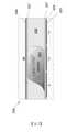
圖3係以剖面型式(未按比例)顯示本發明之活性分子輸送裝置300設置於皮膚380上時的操作原理。活性分子輸送裝置300建構於一個或更多個基板310/315上,此等基板可為撓性基板。共同電極340係藉間隔物330而與驅動電極345間隔。待輸送之活性分子(藥物)溶解於水滴320中,該水滴懸浮於不相容溶劑325(譬如,烴、聚矽氧、或氟化有機油)中。如以上討論者,施加適當電壓至共同電極340及驅動電極345上,可用於使水滴320沿側向朝通道360移動,該通道360耦合至多孔擴散層370(由左至右)。為促進水滴320之運動,疏水層335係設於共同電極340下方及驅動電極345上方。介電層350係介於疏水層335與驅動電極345中間。3 is a cross-sectional view (not to scale) showing the principle of operation of the active
本發明之裝置包含一個或更多個通道360(即,沿z方向之通道),其貫通或鄰接驅動電極345。當水滴320位在此通道360上方時,如圖4中所顯示者,該等活性分子可移動通過通道360而至多孔擴散層370,該多孔擴散層370係與輸送表面、譬如病患之皮膚380接觸。在該位置處,水滴320與接觸皮膚380之多孔擴散層370之間建立擴散接觸。典型地,通道360將包含有助於該溶劑與活性混合物從疏水表面335移動到多孔擴散層370之結構。例如,該通道可包含使親水材料透過毛細管作用而移動之材料,譬如滲透芯纖維、纖維素、或棉。此類材料可塗佈額外疏水塗層,以促進水溶液從電濕潤表面移動到多孔擴散層370。在某些具體實施例中,生物相容黏合劑(未顯示)可積層至該多孔擴散層。該生物相容黏合劑將容許活性分子通過,且同時保持該裝置在使用者上固定不動。合適之生物相容黏合劑可從3M(明尼亞波利斯,明尼蘇達州)取得。Devices of the present invention include one or more channels 360 (ie, channels in the z-direction) that pass through or adjoin drive
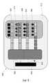
圖5顯示本發明之活性分子輸送裝置500的具體實施例之上視圖,猶如頂部電極及頂部基板已移除者。活性分子輸送裝置500包含基板515、驅動電極545、通道560、及多孔擴散層570。該活性分子輸送裝置500附帶地包含控制器543,該控制器藉走線547而耦合至驅動電極545。如圖5中所顯示者,含待輸送目標分子(藥物)之親水液體位於貯器590中、即該裝置中遠離與皮膚接觸之該多孔擴散層的區域中。Figure 5 shows a top view of an embodiment of an active
圖5中係由底部驅動電極進行到頂部驅動電極來圖示包含活性分子之溶液的輸送順序。起初,複數個小滴520從貯器590彈開,藉此決定將要輸送之劑量(濃度x體積x小滴數量)。小滴520前進,直到鄰近一個或更多個通道560,隨後使用圍繞通道560之輔助驅動電極548,以正交電濕潤將小滴520移動到通道560上方。基於通道560之滲透芯作用,小滴520將移動入且通過通道560,隨後輸送至下方之多孔擴散層570。緣是,該(等)貯器590中之活性成分可移動到該多孔擴散層中。The delivery sequence of the solution containing active molecules is illustrated in FIG. 5 from the bottom drive electrode to the top drive electrode. Initially, a plurality of
可能設想到眾多不同之驅動電極545關於通道560的配置。在圖6中所圖示之第二具體實施例中,電濕潤力係用於從貯器690抽出流體620,且直接將該流體轉運至通道660。裝置600包括基板615、驅動電極645、通道660、及多孔擴散層670。該裝置附帶地包含控制器643,該控制器藉走線647而耦合至驅動電極645。然而,圖6中無需正交運動。藉合適材料在驅動電極645與多孔擴散層670之間提供的毛細管力係從貯器690抽出流體620。儘管顯示流體620呈連續,然請了解到,該流體可如圖5中者以小滴輸送。如圖6中所顯示者,每一通道660各耦合至唯一貯器690。這容許每一貯器皆作用如單一劑,藉此降低系統之複雜度,譬如其中必須彈開及輸送特定劑量之特定體積的特定數量小滴。例如,裝置600可包含七個完全相同之貯器,且控制器643佈設成連續七日每天早上投給一貯器之內容物。另一選擇為,不同貯器690可各含不同濃度之相同活性物,使得受試者可接受第一較強劑量之活性物,且接著在該日中接受一個或更多個較低濃度之保持劑量。此類裝置特別地非常適合輸送荷爾蒙。Numerous different configurations of
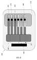
圖7中顯示本發明之另一具體實施例,其中裝置700包含基板715、驅動電極745、通道760、及多孔擴散層770。儘管未顯示控制器,然請了解到,需要控制器來協調該等驅動電極745之功能。圖7圖示出,可能在輸送活性分子之前,在「晶片上」進行反應。如圖7中所顯示者,第一貯器「A」791與第二貯器「B」792二者皆與混合區793流體連通。第一前驅物分子可內含於第一貯器791中之第一溶液內,且同時第二前驅物分子可內含於第二貯器792中之一第二溶液內。在投給活性物之前,該第一溶液與該第二溶液被帶至混合區793中,該等溶液被容許在該混合區中混合以產生目標活性物,該目標活性物接著依上述方法被輸送至多孔擴散層770。Another embodiment of the present invention is shown in FIG. 7 , wherein a
裝置700具有在輸送目標活性物至多孔擴散層770前混合前驅物之能力時,將有眾多優點。例如,該第一前驅物可為敏感性生物體物,譬如抗體或寡核苷酸,其必須在不適合經由該多孔擴散層來輸送之溶液中穩定化而加以儲存。緣是,當適於輸送該生物體時,將從第一貯器791轉運一數量之該生物體至混合區793,該生物體可在該混合區活化、潔淨、或作為目標,以進行輸送(譬如,透過與促進劑、標記物、或其他目標特定分子之接合作用(conjugation))。此類架構可大幅增加生物體之架儲期,且可容許病患避免必須至診所透過靜脈注射來輸送生物體。在其他選擇中,該第一與第二前驅物可為前驅藥,該等前驅藥相結合以產生類鴉片。使用本發明之裝置,由於僅具有該裝置及適當安全許可之使用者可結合該等前驅物來產生該類鴉片,因此可能防止非法之類鴉片投給。The
圖7之系統亦可適合於輸送所謂「雞尾酒式藥物」,該雞尾酒式藥物包含複數個可隨著時間而彼此去活化之活性分子,且典型地必須在譬如化學治療診所之診所中投給。圖7之系統亦可用於輸送譬如病患自己之細胞、抗體等。在此類具體實施例中,病患自己之生物材料可容納於第一貯器中,且當適於輸送治療物時,該病患自己之生物材料將移動到混合區中,以在輸送至該多孔擴散層前,在該混合區與另一活性成分結合。The system of Figure 7 is also suitable for the delivery of so-called "drug cocktails" comprising a plurality of active molecules that deactivate each other over time, and which typically must be administered in a clinic such as a chemotherapy clinic. The system of Figure 7 can also be used to deliver, for example, the patient's own cells, antibodies, and the like. In such embodiments, the patient's own biological material may be contained in the first reservoir, and when suitable for delivery of the therapeutic agent, the patient's own biological material will move into the mixing zone for delivery to the Before the porous diffusion layer, it is combined with another active ingredient in the mixing zone.
控制器543、643、743可包括電池及電子裝置,以符合起始電濕潤移動所需,及譬如為適當之電子裝置/天線等構件以與外界通訊。在較佳的配置中,不可能在未施加電氣訊號下,將含藥物之水滴轉運至通道。這將確保未活化之貼片可經受各式應力(機械、熱等)而不致釋放活性成分。The
在某一具體實施例中,本發明之裝置可用於輸送那若松(NARCAN™)。該裝置將從貯器輸送大約20到100毫克之藥物至該多孔擴散區。假設該貯器中之水中有50毫克/毫升之接近飽和濃度的活性物(譬如,那若松),則需輸送之滴的體積將大約為400到2000微升,這係在裝置之能力內。在其他具體實施例中,本發明之裝置可用於輸送類鴉片,譬如二氫嗎啡酮、氫可酮、酚太尼枸橡酸鹽、美沙酮、或羥考酮。本發明之裝置可用於輸送興奮劑,例如尼古丁、類固醇(譬如,強體松)、及荷爾蒙(譬如,腎上腺素)。In a specific embodiment, the device of the present invention may be used to deliver narokone (NARCAN™). The device will deliver approximately 20 to 100 mg of drug from the reservoir to the porous diffusion zone. Assuming a near-saturated concentration of 50 mg/ml of active (eg, narokatsu) in the water in the reservoir, the volume of droplets to be delivered would be approximately 400 to 2000 microliters, which is within the capabilities of the device. In other embodiments, the devices of the present invention can be used to deliver opioids, such as hydromorphone, hydrocodone, fentanyl citrate, methadone, or oxycodone. The devices of the present invention can be used to deliver stimulants such as nicotine, steroids (eg, prednisone), and hormones (eg, epinephrine).
在某些具體實施例中,本發明之裝置可製成撓性者,使得該裝置可在彎曲表面880上展開、及/或整合入撓性包裝中,以改良使用者舒適性及順應性。此類裝置800之一具體實施例顯示於圖8中,其中撓性驅動電極845耦合至一多孔擴散層870,且通道860提供撓性驅動電極845與多孔擴散層870之間的流體連通。如圖8中所顯示者,控制器843及貯器890可結合入同一外殼中。在具體實施例中,裝置800可呈腕套外型,其中裝置800可藉裝飾設計額外地擴大,以遮掩裝置800實際上係用於經皮輸送藥物。In certain embodiments, the devices of the present invention can be made flexible such that the device can be deployed over
活性分子輸送系統之先進具體實施例將包含電路,以容許藉譬如智慧型手機或智慧型手錶等次要裝置來無線控制該活性分子輸送系統。藉由此類改善,使用者可控制譬如待輸送之活性分子類型、及待輸送之量。使用在譬如智慧型手機或手錶上之應用軟體,可能以程式設定該裝置,以根據一天中的時間來改變活性分子之輸送量。在其他具體實施例中,該裝置可與譬如健身追蹤器或心律監視器等生物量測感測器操作性地耦合,如此該應用軟體可當譬如使用者之脈搏數超過一預設臨界時關閉配藥。其他具體實施例可將來自葡萄糖監視器之示值讀數耦合至該裝置,以當病患處於其期望血糖濃度範圍之外時,自動輸送胰島素。Advanced embodiments of the active molecule delivery system would include circuitry to allow wireless control of the active molecule delivery system by a secondary device such as a smartphone or smart watch. With such improvements, the user can control, for example, the type of active molecule to be delivered, and the amount to be delivered. Using an application such as a smartphone or watch, the device may be programmed to vary the delivery of active molecules depending on the time of day. In other embodiments, the device may be operatively coupled with a biometric sensor, such as a fitness tracker or heart rate monitor, such that the application may shut down when, for example, the user's pulse rate exceeds a predetermined threshold Dispensing. Other embodiments may couple readings from a glucose monitor to the device to automatically deliver insulin when the patient is outside of their desired blood glucose concentration range.
當期望時,可遠端啟動及/或控制本發明之裝置。例如,近場通訊(NFC)、藍芽、WIFI、或其他無線通訊功能可用於啟動裝置,且促使投劑。更,相同之無線通訊可用於監視該裝置之性能,譬如得知在不同驅動狀態下所有該(等)貯器之百分率及區域,這意謂醫療服務提供者或治療師將可取得所有使用數據,包含貼片何時活化及活性物之投給量。關於「可程式設定」特徵,由於每一貯器皆可獨立地變化,因此可藉在不同時間從不同貯器驅動不同濃度之活性物、或不同之活性物,而以程式設定該裝置之總釋放廓形(overall release profile)。此外,由於用來活化貼片之智慧型裝置亦可與遠端醫師通訊來共享數據,因此病患順應性亦良好。When desired, the device of the present invention can be remotely activated and/or controlled. For example, Near Field Communication (NFC), Bluetooth, WIFI, or other wireless communication functions can be used to activate the device and cause the dose to be administered. Furthermore, the same wireless communication can be used to monitor the performance of the device, such as to know the percentage and area of all the receptacle(s) under different actuation states, which means that all usage data will be available to a healthcare provider or therapist , including when the patch is activated and the dosage of the active substance. Regarding the "programmable" feature, since each reservoir can be changed independently, it is possible to program the total amount of the device by driving different concentrations of actives, or different actives, from different reservoirs at different times. The overall release profile. In addition, since the smart device used to activate the patch can also communicate with remote physicians to share data, patient compliance is also good.
熟於此技藝者將明白,可在上述之發明特定具體實施例中實施眾多變更及修飾,而不致脫離本發明之範圍。緣是,前述說明之全體應以例證而非限制性意義解釋。Those skilled in the art will appreciate that numerous changes and modifications can be made in the specific embodiments of the invention described above without departing from the scope of the invention. As a matter of fact, the entirety of the foregoing description should be interpreted in an illustrative rather than a restrictive sense.
200:介電濕潤202:油204:小水滴205:驅動電極206:頂部電極207:疏水塗層208:介電層300:活性分子輸送裝置310:基板315:基板320:水滴325:不相容溶劑330:間隔物335:疏水層340:共同電極345:驅動電極350:介電層360:通道370:多孔擴散層380:皮膚500:活性分子輸送裝置515:基板520:小滴543:控制器545:驅動電極547:走線548:輔助驅動電極560:通道570:多孔擴散層590:貯器600:裝置615:基板620:流體643:控制器645:驅動電極647:走線660:通道670:多孔擴散層690:貯器700:裝置715:基板745:驅動電極760:通道770:多孔擴散層791:第一貯器792:第二貯器793:混合區800:裝置843:控制器845:撓性驅動電極860:通道870:多孔擴散層880:彎曲表面890:貯器200: Dielectric Wetting202: Oil204: Small water droplets205: Drive Electrodes206: Top electrode207: Hydrophobic Coating208: Dielectric Layer300: Active Molecule Delivery Device310: Substrate315: Substrate320: water droplets325: Incompatible Solvents330: Spacer335: Hydrophobic layer340: Common Electrode345: Drive Electrode350: Dielectric Layer360: Channel370: Porous Diffusion Layer380: Skin500: Active Molecular Delivery Device515: Substrate520: Droplets543: Controller545: Drive Electrode547: Route548: Auxiliary drive electrode560: channel570: Porous Diffusion Layer590: Reservoir600: Device615: Substrate620: Fluid643: Controller645: Drive Electrode647: Route660: Channel670: Porous Diffusion Layer690: Reservoir700: Device715: Substrate745: Drive Electrode760: Channel770: Porous Diffusion Layer791: First receptacle792: Second receptacle793: Mixed Zone800: Device843: Controller845: Flexible Drive Electrode860: Channel870: Porous Diffusion Layer880: Curved Surface890: Receptacle
圖1顯示先前技藝EWoD裝置,其包含在相同主動矩陣上之推進及感測二者。Figure 1 shows a prior art EWoD device that includes both driving and sensing on the same active matrix.
圖2描繪出,藉由在相鄰電極上提供不同帶電狀態,而使水相小滴在相鄰電極之間運動。Figure 2 depicts the movement of aqueous phase droplets between adjacent electrodes by providing different charge states on adjacent electrodes.
圖3描繪出,當裝置處於「關閉」狀態、亦即活性物尚未裝入時之本發明的一剖面。Figure 3 depicts a cross-section of the present invention when the device is in the "off" state, ie when the active has not been loaded.
圖4描繪出,當裝置處於「啟動」狀態、亦即活性物已裝入時之本發明的一剖面。Figure 4 depicts a cross-section of the present invention when the device is in the "activated" state, ie when the actives are loaded.
圖5係包含活性材料的貯器、驅動電極、通道、及多孔擴散層之本發明裝置的平面視圖。圖5顯示逐步(下至上)分配包含活性分子之溶液、朝通道移動小滴、移動到通道、及分配小滴至多孔擴散層中。Figure 5 is a plan view of a device of the present invention comprising a reservoir of active material, drive electrodes, channels, and porous diffusion layers. Figure 5 shows stepwise (bottom to top) dispensing of a solution containing active molecules, moving droplets towards channels, moving into channels, and dispensing droplets into a porous diffusion layer.
圖6係圖示本發明裝置,其中每一通道耦合至僅單一個貯器。在某些具體實施例中,每一貯器內含不同濃度之活性分子,藉此容許動態地控制劑量。Figure 6 illustrates a device of the present invention wherein each channel is coupled to only a single reservoir. In certain embodiments, each reservoir contains a different concentration of active molecule, thereby allowing for dynamic control of dosage.
圖7係圖示本發明裝置,其中二個不同貯器耦合至混合區,藉此可使二組分「A」與「B」在輸送至多孔擴散層前混合。Figure 7 illustrates a device of the present invention wherein two different reservoirs are coupled to a mixing zone whereby the two components "A" and "B" can be mixed prior to delivery to the porous diffusion layer.
圖8係圖示本發明輸送裝置,其中驅動電極呈撓性,藉此容許輸送裝置纏繞於譬如臂或腿等肢體。Figure 8 illustrates a delivery device of the present invention wherein the drive electrodes are flexible, thereby allowing the delivery device to wrap around a limb such as an arm or leg.
700:裝置700: Device
715:基板715: Substrate
745:驅動電極745: Drive Electrode
760:通道760: Channel
770:多孔擴散層770: Porous Diffusion Layer
791:第一貯器791: First receptacle
792:第二貯器792: Second receptacle
793:混合區793: Mixed Zone
Claims (6)
Translated fromChineseApplications Claiming Priority (2)
| Application Number | Priority Date | Filing Date | Title |
|---|---|---|---|
| US201862745718P | 2018-10-15 | 2018-10-15 | |
| US62/745,718 | 2018-10-15 |
Publications (2)
| Publication Number | Publication Date |
|---|---|
| TW202135886A TW202135886A (en) | 2021-10-01 |
| TWI763526Btrue TWI763526B (en) | 2022-05-01 |
Family
ID=70159689
Family Applications (2)
| Application Number | Title | Priority Date | Filing Date |
|---|---|---|---|
| TW110120568ATWI763526B (en) | 2018-10-15 | 2019-10-15 | Method for dispensing an aqueous chemical species to a surface |
| TW108137032ATWI730448B (en) | 2018-10-15 | 2019-10-15 | Digital microfluidic delivery device |
Family Applications After (1)
| Application Number | Title | Priority Date | Filing Date |
|---|---|---|---|
| TW108137032ATWI730448B (en) | 2018-10-15 | 2019-10-15 | Digital microfluidic delivery device |
Country Status (7)
| Country | Link |
|---|---|
| US (2) | US11511096B2 (en) |
| EP (1) | EP3866903A4 (en) |
| JP (1) | JP7100206B2 (en) |
| KR (1) | KR102577837B1 (en) |
| CN (1) | CN112839700B (en) |
| TW (2) | TWI763526B (en) |
| WO (1) | WO2020081478A1 (en) |
Families Citing this family (10)
| Publication number | Priority date | Publication date | Assignee | Title |
|---|---|---|---|---|
| KR102737615B1 (en)* | 2019-03-11 | 2024-12-04 | 엘지이노텍 주식회사 | Ultrasonic wave mask and skin care device including the same |
| WO2021102134A1 (en) | 2019-11-20 | 2021-05-27 | E Ink Corporation | Spatially variable hydrophobic layers for digital microfluidics |
| US11554374B2 (en) | 2020-01-17 | 2023-01-17 | Nuclera Nucleics Ltd. | Spatially variable dielectric layers for digital microfluidics |
| US11946901B2 (en) | 2020-01-27 | 2024-04-02 | Nuclera Ltd | Method for degassing liquid droplets by electrical actuation at higher temperatures |
| CN115175764A (en) | 2020-02-18 | 2022-10-11 | 核酸有限公司 | Adaptive gate drive for high frequency AC drive of EWoD array |
| EP4106920A4 (en) | 2020-02-19 | 2024-03-20 | Nuclera Ltd | Latched transistor driving for high frequency ac driving of ewod arrays |
| WO2021222061A1 (en) | 2020-04-27 | 2021-11-04 | Nuclera Nucleics Ltd. | Segmented top plate for variable driving and short protection for digital microfluidics |
| CN114585441B (en)* | 2020-09-29 | 2024-01-23 | 京东方科技集团股份有限公司 | Microfluidic chip, library preparation chip and liquid drop control driving method |
| WO2022216283A1 (en)* | 2021-04-07 | 2022-10-13 | Hewlett-Packard Development Company, L.P. | Dielectric layer for microfluidic receptacle |
| WO2024064882A1 (en)* | 2022-09-23 | 2024-03-28 | Spotless Materials Inc. | Repellent coating formulation with low volatile organic compounds |
Citations (4)
| Publication number | Priority date | Publication date | Assignee | Title |
|---|---|---|---|---|
| WO2004077017A2 (en)* | 2003-02-21 | 2004-09-10 | West Virginia University Research Corporation | Apparatus and method for on-chip concentration using a microfluidic device with an integrated ultrafiltration membrane structure |
| WO2017075295A1 (en)* | 2015-10-27 | 2017-05-04 | Berkeley Lights, Inc. | Microfluidic electrowetting device apparatus having a covalently bound hydrophobic surface |
| TWM541866U (en)* | 2016-11-22 | 2017-05-21 | Chien-Chuan Chen | Soft membrane microelectrode device |
| WO2018175829A1 (en)* | 2017-03-24 | 2018-09-27 | E Ink California, Llc | Microcell delivery systems including charged or magnetic particles for regulating rate of administration of actives |
Family Cites Families (319)
| Publication number | Priority date | Publication date | Assignee | Title |
|---|---|---|---|---|
| US4708716A (en) | 1983-08-18 | 1987-11-24 | Drug Delivery Systems Inc. | Transdermal drug applicator |
| US4573995A (en) | 1984-10-09 | 1986-03-04 | Alza Corporation | Transdermal therapeutic systems for the administration of naloxone, naltrexone and nalbuphine |
| US5080646A (en)* | 1988-10-03 | 1992-01-14 | Alza Corporation | Membrane for electrotransport transdermal drug delivery |
| US5311337A (en) | 1992-09-23 | 1994-05-10 | Honeywell Inc. | Color mosaic matrix display having expanded or reduced hexagonal dot pattern |
| JP2572702B2 (en) | 1992-10-26 | 1997-01-16 | セイコーエプソン株式会社 | Display device |
| US7956841B2 (en) | 1995-07-20 | 2011-06-07 | E Ink Corporation | Stylus-based addressing structures for displays |
| US6639578B1 (en) | 1995-07-20 | 2003-10-28 | E Ink Corporation | Flexible displays |
| US7167155B1 (en) | 1995-07-20 | 2007-01-23 | E Ink Corporation | Color electrophoretic displays |
| US7352353B2 (en) | 1995-07-20 | 2008-04-01 | E Ink Corporation | Electrostatically addressable electrophoretic display |
| US7327511B2 (en) | 2004-03-23 | 2008-02-05 | E Ink Corporation | Light modulators |
| US6118426A (en) | 1995-07-20 | 2000-09-12 | E Ink Corporation | Transducers and indicators having printed displays |
| US6120588A (en) | 1996-07-19 | 2000-09-19 | E Ink Corporation | Electronically addressable microencapsulated ink and display thereof |
| US6710540B1 (en) | 1995-07-20 | 2004-03-23 | E Ink Corporation | Electrostatically-addressable electrophoretic display |
| US6664944B1 (en) | 1995-07-20 | 2003-12-16 | E-Ink Corporation | Rear electrode structures for electrophoretic displays |
| US7259744B2 (en) | 1995-07-20 | 2007-08-21 | E Ink Corporation | Dielectrophoretic displays |
| US8089453B2 (en) | 1995-07-20 | 2012-01-03 | E Ink Corporation | Stylus-based addressing structures for displays |
| US7106296B1 (en) | 1995-07-20 | 2006-09-12 | E Ink Corporation | Electronic book with multiple page displays |
| US7999787B2 (en) | 1995-07-20 | 2011-08-16 | E Ink Corporation | Methods for driving electrophoretic displays using dielectrophoretic forces |
| US7411719B2 (en) | 1995-07-20 | 2008-08-12 | E Ink Corporation | Electrophoretic medium and process for the production thereof |
| US8139050B2 (en) | 1995-07-20 | 2012-03-20 | E Ink Corporation | Addressing schemes for electronic displays |
| US7193625B2 (en) | 1999-04-30 | 2007-03-20 | E Ink Corporation | Methods for driving electro-optic displays, and apparatus for use therein |
| US7583251B2 (en) | 1995-07-20 | 2009-09-01 | E Ink Corporation | Dielectrophoretic displays |
| US6124851A (en) | 1995-07-20 | 2000-09-26 | E Ink Corporation | Electronic book with multiple page displays |
| DE69636960C5 (en) | 1996-07-19 | 2015-07-30 | E-Ink Corp. | Electronically addressable microencapsulated ink |
| US5930026A (en) | 1996-10-25 | 1999-07-27 | Massachusetts Institute Of Technology | Nonemissive displays and piezoelectric power supplies therefor |
| US6980196B1 (en) | 1997-03-18 | 2005-12-27 | Massachusetts Institute Of Technology | Printable electronic display |
| US7002728B2 (en) | 1997-08-28 | 2006-02-21 | E Ink Corporation | Electrophoretic particles, and processes for the production thereof |
| US6825829B1 (en) | 1997-08-28 | 2004-11-30 | E Ink Corporation | Adhesive backed displays |
| US6177921B1 (en) | 1997-08-28 | 2001-01-23 | E Ink Corporation | Printable electrode structures for displays |
| US6252564B1 (en) | 1997-08-28 | 2001-06-26 | E Ink Corporation | Tiled displays |
| US6232950B1 (en) | 1997-08-28 | 2001-05-15 | E Ink Corporation | Rear electrode structures for displays |
| US6445489B1 (en) | 1998-03-18 | 2002-09-03 | E Ink Corporation | Electrophoretic displays and systems for addressing such displays |
| US6704133B2 (en) | 1998-03-18 | 2004-03-09 | E-Ink Corporation | Electro-optic display overlays and systems for addressing such displays |
| US6753999B2 (en) | 1998-03-18 | 2004-06-22 | E Ink Corporation | Electrophoretic displays in portable devices and systems for addressing such displays |
| US6518949B2 (en) | 1998-04-10 | 2003-02-11 | E Ink Corporation | Electronic displays using organic-based field effect transistors |
| US7075502B1 (en) | 1998-04-10 | 2006-07-11 | E Ink Corporation | Full color reflective display with multichromatic sub-pixels |
| WO1999059101A2 (en) | 1998-05-12 | 1999-11-18 | E-Ink Corporation | Microencapsulated electrophoretic electrostatically-addressed media for drawing device applications |
| US6241921B1 (en) | 1998-05-15 | 2001-06-05 | Massachusetts Institute Of Technology | Heterogeneous display elements and methods for their fabrication |
| CA2333358A1 (en) | 1998-06-22 | 1999-12-29 | E Ink Corporation | Means of addressing microencapsulated display media |
| ATE228681T1 (en) | 1998-07-08 | 2002-12-15 | E Ink Corp | METHOD AND DEVICE FOR MEASURING THE STATE OF AN ELECTROPHORETIC DISPLAY DEVICE |
| US20030102858A1 (en) | 1998-07-08 | 2003-06-05 | E Ink Corporation | Method and apparatus for determining properties of an electrophoretic display |
| ATE215255T1 (en) | 1998-07-22 | 2002-04-15 | E Ink Corp | ELECTRONIC DISPLAY |
| USD485294S1 (en) | 1998-07-22 | 2004-01-13 | E Ink Corporation | Electrode structure for an electronic display |
| US7256766B2 (en) | 1998-08-27 | 2007-08-14 | E Ink Corporation | Electrophoretic display comprising optical biasing element |
| EP1118039B1 (en) | 1998-10-07 | 2003-02-05 | E Ink Corporation | Illumination system for nonemissive electronic displays |
| AU1811300A (en) | 1998-11-02 | 2000-05-22 | E-Ink Corporation | Broadcast system for display devices made of electronic ink |
| US20070285385A1 (en) | 1998-11-02 | 2007-12-13 | E Ink Corporation | Broadcast system for electronic ink signs |
| US6506438B2 (en) | 1998-12-15 | 2003-01-14 | E Ink Corporation | Method for printing of transistor arrays on plastic substrates |
| US6312304B1 (en) | 1998-12-15 | 2001-11-06 | E Ink Corporation | Assembly of microencapsulated electronic displays |
| WO2000036560A1 (en) | 1998-12-18 | 2000-06-22 | E Ink Corporation | Electronic ink display media for security and authentication |
| US6724519B1 (en) | 1998-12-21 | 2004-04-20 | E-Ink Corporation | Protective electrodes for electrophoretic displays |
| AU2591400A (en) | 1998-12-22 | 2000-07-12 | E-Ink Corporation | Method of manufacturing of a discrete electronic device |
| US6498114B1 (en) | 1999-04-09 | 2002-12-24 | E Ink Corporation | Method for forming a patterned semiconductor film |
| US6842657B1 (en) | 1999-04-09 | 2005-01-11 | E Ink Corporation | Reactive formation of dielectric layers and protection of organic layers in organic semiconductor device fabrication |
| US7012600B2 (en) | 1999-04-30 | 2006-03-14 | E Ink Corporation | Methods for driving bistable electro-optic displays, and apparatus for use therein |
| US6504524B1 (en) | 2000-03-08 | 2003-01-07 | E Ink Corporation | Addressing methods for displays having zero time-average field |
| US6531997B1 (en) | 1999-04-30 | 2003-03-11 | E Ink Corporation | Methods for addressing electrophoretic displays |
| US7119772B2 (en) | 1999-04-30 | 2006-10-10 | E Ink Corporation | Methods for driving bistable electro-optic displays, and apparatus for use therein |
| US8009348B2 (en) | 1999-05-03 | 2011-08-30 | E Ink Corporation | Machine-readable displays |
| US7119759B2 (en) | 1999-05-03 | 2006-10-10 | E Ink Corporation | Machine-readable displays |
| US7030412B1 (en) | 1999-05-05 | 2006-04-18 | E Ink Corporation | Minimally-patterned semiconductor devices for display applications |
| AU5779200A (en) | 1999-07-01 | 2001-01-22 | E-Ink Corporation | Electrophoretic medium provided with spacers |
| AU7137800A (en) | 1999-07-21 | 2001-02-13 | E-Ink Corporation | Preferred methods for producing electrical circuit elements used to control an electronic display |
| EP1196814A1 (en) | 1999-07-21 | 2002-04-17 | E Ink Corporation | Use of a storage capacitor to enhance the performance of an active matrix driven electronic display |
| WO2001017040A1 (en) | 1999-08-31 | 2001-03-08 | E Ink Corporation | A solvent annealing process for forming a thin semiconductor film with advantageous properties |
| AU7091400A (en) | 1999-08-31 | 2001-03-26 | E-Ink Corporation | Transistor for an electronically driven display |
| CN1237623C (en) | 2000-04-18 | 2006-01-18 | 伊英克公司 | Method for forming transistor on substrate and substrate containing polyphenylene polyimide |
| US7893435B2 (en) | 2000-04-18 | 2011-02-22 | E Ink Corporation | Flexible electronic circuits and displays including a backplane comprising a patterned metal foil having a plurality of apertures extending therethrough |
| US6683333B2 (en) | 2000-07-14 | 2004-01-27 | E Ink Corporation | Fabrication of electronic circuit elements using unpatterned semiconductor layers |
| WO2002007503A1 (en) | 2000-07-25 | 2002-01-31 | The Regents Of The University Of California | Electrowetting-driven micropumping |
| US6816147B2 (en) | 2000-08-17 | 2004-11-09 | E Ink Corporation | Bistable electro-optic display, and method for addressing same |
| JP2004522179A (en) | 2000-11-29 | 2004-07-22 | イー−インク コーポレイション | Addressing scheme for electronic displays |
| US20020090980A1 (en) | 2000-12-05 | 2002-07-11 | Wilcox Russell J. | Displays for portable electronic apparatus |
| AU2002250304A1 (en) | 2001-03-13 | 2002-09-24 | E Ink Corporation | Apparatus for displaying drawings |
| US7679814B2 (en) | 2001-04-02 | 2010-03-16 | E Ink Corporation | Materials for use in electrophoretic displays |
| KR100824249B1 (en) | 2001-04-02 | 2008-04-24 | 이 잉크 코포레이션 | Electrophoretic display including electrophoretic media with improved image stability |
| DE60216924T2 (en) | 2001-07-09 | 2007-04-05 | E Ink Corp., Cambridge | ELECTROOPTICAL DISPLAY AND ADHESIVE COMPOSITION |
| US7535624B2 (en) | 2001-07-09 | 2009-05-19 | E Ink Corporation | Electro-optic display and materials for use therein |
| US7110163B2 (en) | 2001-07-09 | 2006-09-19 | E Ink Corporation | Electro-optic display and lamination adhesive for use therein |
| WO2003007066A2 (en) | 2001-07-09 | 2003-01-23 | E Ink Corporation | Electro-optical display having a lamination adhesive layer |
| US6982178B2 (en) | 2002-06-10 | 2006-01-03 | E Ink Corporation | Components and methods for use in electro-optic displays |
| US6967640B2 (en) | 2001-07-27 | 2005-11-22 | E Ink Corporation | Microencapsulated electrophoretic display with integrated driver |
| US6819471B2 (en) | 2001-08-16 | 2004-11-16 | E Ink Corporation | Light modulation by frustration of total internal reflection |
| US7038670B2 (en) | 2002-08-16 | 2006-05-02 | Sipix Imaging, Inc. | Electrophoretic display with dual mode switching |
| US6825970B2 (en) | 2001-09-14 | 2004-11-30 | E Ink Corporation | Methods for addressing electro-optic materials |
| US8125501B2 (en) | 2001-11-20 | 2012-02-28 | E Ink Corporation | Voltage modulated driver circuits for electro-optic displays |
| US8558783B2 (en) | 2001-11-20 | 2013-10-15 | E Ink Corporation | Electro-optic displays with reduced remnant voltage |
| US8593396B2 (en) | 2001-11-20 | 2013-11-26 | E Ink Corporation | Methods and apparatus for driving electro-optic displays |
| US7202847B2 (en) | 2002-06-28 | 2007-04-10 | E Ink Corporation | Voltage modulated driver circuits for electro-optic displays |
| US7528822B2 (en) | 2001-11-20 | 2009-05-05 | E Ink Corporation | Methods for driving electro-optic displays |
| US7952557B2 (en) | 2001-11-20 | 2011-05-31 | E Ink Corporation | Methods and apparatus for driving electro-optic displays |
| US9412314B2 (en) | 2001-11-20 | 2016-08-09 | E Ink Corporation | Methods for driving electro-optic displays |
| WO2003045556A2 (en) | 2001-11-26 | 2003-06-05 | Keck Graduate Institute | Method, apparatus and article for microfluidic control via electrowetting, for chemical, biochemical and biological assays and the like |
| US6865010B2 (en) | 2001-12-13 | 2005-03-08 | E Ink Corporation | Electrophoretic electronic displays with low-index films |
| US6900851B2 (en) | 2002-02-08 | 2005-05-31 | E Ink Corporation | Electro-optic displays and optical systems for addressing such displays |
| US6950220B2 (en) | 2002-03-18 | 2005-09-27 | E Ink Corporation | Electro-optic displays, and methods for driving same |
| TWI240842B (en) | 2002-04-24 | 2005-10-01 | Sipix Imaging Inc | Matrix driven electrophoretic display with multilayer back plane |
| TW574538B (en) | 2002-04-24 | 2004-02-01 | Sipix Imaging Inc | Compositions and processes for format flexible roll-to-roll manufacturing of electrophoretic displays |
| US7116318B2 (en) | 2002-04-24 | 2006-10-03 | E Ink Corporation | Backplanes for display applications, and components for use therein |
| US7190008B2 (en) | 2002-04-24 | 2007-03-13 | E Ink Corporation | Electro-optic displays, and components for use therein |
| US7223672B2 (en) | 2002-04-24 | 2007-05-29 | E Ink Corporation | Processes for forming backplanes for electro-optic displays |
| TW583497B (en) | 2002-05-29 | 2004-04-11 | Sipix Imaging Inc | Electrode and connecting designs for roll-to-roll format flexible display manufacturing |
| US8049947B2 (en) | 2002-06-10 | 2011-11-01 | E Ink Corporation | Components and methods for use in electro-optic displays |
| US7583427B2 (en) | 2002-06-10 | 2009-09-01 | E Ink Corporation | Components and methods for use in electro-optic displays |
| US7649674B2 (en) | 2002-06-10 | 2010-01-19 | E Ink Corporation | Electro-optic display with edge seal |
| US7554712B2 (en) | 2005-06-23 | 2009-06-30 | E Ink Corporation | Edge seals for, and processes for assembly of, electro-optic displays |
| US20110199671A1 (en) | 2002-06-13 | 2011-08-18 | E Ink Corporation | Methods for driving electrophoretic displays using dielectrophoretic forces |
| US20080024482A1 (en) | 2002-06-13 | 2008-01-31 | E Ink Corporation | Methods for driving electro-optic displays |
| US6842279B2 (en) | 2002-06-27 | 2005-01-11 | E Ink Corporation | Illumination system for nonemissive electronic displays |
| US7347957B2 (en) | 2003-07-10 | 2008-03-25 | Sipix Imaging, Inc. | Methods and compositions for improved electrophoretic display performance |
| TWI314237B (en) | 2002-07-17 | 2009-09-01 | Sipix Imaging Inc | Novel methods and compositions for improved electrophoretic display performance |
| US8547628B2 (en) | 2002-07-17 | 2013-10-01 | Sipix Imaging, Inc. | Methods and compositions for improved electrophoretic display performance |
| US20060255322A1 (en) | 2002-07-17 | 2006-11-16 | Wu Zarng-Arh G | Methods and compositions for improved electrophoretic display performance |
| EP1527371B1 (en) | 2002-08-06 | 2012-10-03 | E Ink Corporation | Protection of electro-optic displays against thermal effects |
| US7839564B2 (en) | 2002-09-03 | 2010-11-23 | E Ink Corporation | Components and methods for use in electro-optic displays |
| TW575646B (en) | 2002-09-04 | 2004-02-11 | Sipix Imaging Inc | Novel adhesive and sealing layers for electrophoretic displays |
| US20130063333A1 (en) | 2002-10-16 | 2013-03-14 | E Ink Corporation | Electrophoretic displays |
| KR100937613B1 (en) | 2002-12-16 | 2010-01-20 | 이 잉크 코포레이션 | Backplanes for Electro-Optical Displays |
| US6922276B2 (en) | 2002-12-23 | 2005-07-26 | E Ink Corporation | Flexible electro-optic displays |
| CN100399109C (en) | 2003-03-27 | 2008-07-02 | 伊英克公司 | Electro-optical components |
| US20040246562A1 (en) | 2003-05-16 | 2004-12-09 | Sipix Imaging, Inc. | Passive matrix electrophoretic display driving scheme |
| JP2004356206A (en) | 2003-05-27 | 2004-12-16 | Fuji Photo Film Co Ltd | Laminated structure and its manufacturing method |
| WO2005002305A2 (en) | 2003-06-06 | 2005-01-06 | Sipix Imaging, Inc. | In mold manufacture of an object with embedded display panel |
| US8174490B2 (en) | 2003-06-30 | 2012-05-08 | E Ink Corporation | Methods for driving electrophoretic displays |
| WO2005010598A2 (en) | 2003-07-24 | 2005-02-03 | E Ink Corporation | Electro-optic displays |
| EP1656658A4 (en) | 2003-08-19 | 2009-12-30 | E Ink Corp | Methods for controlling electro-optic displays |
| WO2005029458A1 (en) | 2003-09-19 | 2005-03-31 | E Ink Corporation | Methods for reducing edge effects in electro-optic displays |
| JP2007507737A (en) | 2003-10-03 | 2007-03-29 | コーニンクレッカ フィリップス エレクトロニクス エヌ ヴィ | Electrophoretic display unit |
| US7061662B2 (en) | 2003-10-07 | 2006-06-13 | Sipix Imaging, Inc. | Electrophoretic display with thermal control |
| US8514168B2 (en) | 2003-10-07 | 2013-08-20 | Sipix Imaging, Inc. | Electrophoretic display with thermal control |
| CN101930118B (en) | 2003-10-08 | 2013-05-29 | 伊英克公司 | Electro-wetting displays |
| US8319759B2 (en) | 2003-10-08 | 2012-11-27 | E Ink Corporation | Electrowetting displays |
| US7177066B2 (en) | 2003-10-24 | 2007-02-13 | Sipix Imaging, Inc. | Electrophoretic display driving scheme |
| US20050122306A1 (en) | 2003-10-29 | 2005-06-09 | E Ink Corporation | Electro-optic displays with single edge addressing and removable driver circuitry |
| US20110187683A1 (en) | 2003-10-30 | 2011-08-04 | E Ink Corporation | Electro-optic displays with single edge addressing and removable driver circuitry |
| US7551346B2 (en) | 2003-11-05 | 2009-06-23 | E Ink Corporation | Electro-optic displays, and materials for use therein |
| US7672040B2 (en) | 2003-11-05 | 2010-03-02 | E Ink Corporation | Electro-optic displays, and materials for use therein |
| EP2487674B1 (en) | 2003-11-05 | 2018-02-21 | E Ink Corporation | Electro-optic displays |
| US8177942B2 (en) | 2003-11-05 | 2012-05-15 | E Ink Corporation | Electro-optic displays, and materials for use therein |
| US20110164301A1 (en) | 2003-11-05 | 2011-07-07 | E Ink Corporation | Electro-optic displays, and materials for use therein |
| KR100689311B1 (en) | 2003-11-10 | 2007-03-08 | 엘지.필립스 엘시디 주식회사 | LCD and its driving method |
| EP1692682A1 (en) | 2003-11-25 | 2006-08-23 | Koninklijke Philips Electronics N.V. | A display apparatus with a display device and a cyclic rail-stabilized method of driving the display device |
| US8928562B2 (en) | 2003-11-25 | 2015-01-06 | E Ink Corporation | Electro-optic displays, and methods for driving same |
| US7206119B2 (en) | 2003-12-31 | 2007-04-17 | E Ink Corporation | Electro-optic displays, and method for driving same |
| US7075703B2 (en) | 2004-01-16 | 2006-07-11 | E Ink Corporation | Process for sealing electro-optic displays |
| US7388572B2 (en) | 2004-02-27 | 2008-06-17 | E Ink Corporation | Backplanes for electro-optic displays |
| US7492339B2 (en) | 2004-03-26 | 2009-02-17 | E Ink Corporation | Methods for driving bistable electro-optic displays |
| US8289250B2 (en) | 2004-03-31 | 2012-10-16 | E Ink Corporation | Methods for driving electro-optic displays |
| US20050253777A1 (en) | 2004-05-12 | 2005-11-17 | E Ink Corporation | Tiled displays and methods for driving same |
| CN100557474C (en) | 2004-07-27 | 2009-11-04 | 伊英克公司 | Electro-optic display |
| US20080136774A1 (en) | 2004-07-27 | 2008-06-12 | E Ink Corporation | Methods for driving electrophoretic displays using dielectrophoretic forces |
| US7453445B2 (en) | 2004-08-13 | 2008-11-18 | E Ink Corproation | Methods for driving electro-optic displays |
| US7301693B2 (en) | 2004-08-13 | 2007-11-27 | Sipix Imaging, Inc. | Direct drive display with a multi-layer backplane and process for its manufacture |
| US8643595B2 (en) | 2004-10-25 | 2014-02-04 | Sipix Imaging, Inc. | Electrophoretic display driving approaches |
| US7304780B2 (en) | 2004-12-17 | 2007-12-04 | Sipix Imaging, Inc. | Backplane design for display panels and processes for their manufacture |
| US20090075129A1 (en)* | 2004-12-27 | 2009-03-19 | Integrated Sensing Systems, Inc. | Microfluidic device and method of use |
| WO2006081305A2 (en) | 2005-01-26 | 2006-08-03 | E Ink Corporation | Electrophoretic displays using gaseous fluids |
| JP4718859B2 (en) | 2005-02-17 | 2011-07-06 | セイコーエプソン株式会社 | Electrophoresis apparatus, driving method thereof, and electronic apparatus |
| JP4690079B2 (en) | 2005-03-04 | 2011-06-01 | セイコーエプソン株式会社 | Electrophoresis apparatus, driving method thereof, and electronic apparatus |
| US8576162B2 (en) | 2005-03-14 | 2013-11-05 | Sipix Imaging, Inc. | Manufacturing processes of backplane for segment displays |
| US8159636B2 (en) | 2005-04-08 | 2012-04-17 | Sipix Imaging, Inc. | Reflective displays and processes for their manufacture |
| JP4547301B2 (en) | 2005-05-13 | 2010-09-22 | 株式会社日立ハイテクノロジーズ | Liquid transport device and analysis system |
| EP1893278A2 (en) | 2005-06-03 | 2008-03-05 | Trans-Dermal Patents Company, LLC | Agent delivery system |
| CN101243176B (en) | 2005-06-10 | 2013-07-17 | 康乃尔研究基金会有限公司 | Recirculating microfluidic device and methods of use |
| US20070066934A1 (en)* | 2005-09-19 | 2007-03-22 | Transport Pharmaceuticals, Inc. | Electrokinetic delivery system and methods therefor |
| US7880958B2 (en) | 2005-09-23 | 2011-02-01 | Sipix Imaging, Inc. | Display cell structure and electrode protecting layer compositions |
| US7408699B2 (en) | 2005-09-28 | 2008-08-05 | Sipix Imaging, Inc. | Electrophoretic display and methods of addressing such display |
| TWI274221B (en) | 2005-09-29 | 2007-02-21 | Au Optronics Corp | Active device matrix substrate |
| KR20070041934A (en) | 2005-10-17 | 2007-04-20 | 삼성전자주식회사 | Liquid crystal display |
| US20070176912A1 (en) | 2005-12-09 | 2007-08-02 | Beames Michael H | Portable memory devices with polymeric displays |
| US8610988B2 (en) | 2006-03-09 | 2013-12-17 | E Ink Corporation | Electro-optic display with edge seal |
| US7982479B2 (en) | 2006-04-07 | 2011-07-19 | Sipix Imaging, Inc. | Inspection methods for defects in electrophoretic display and related devices |
| US7683606B2 (en) | 2006-05-26 | 2010-03-23 | Sipix Imaging, Inc. | Flexible display testing and inspection |
| US20080024429A1 (en) | 2006-07-25 | 2008-01-31 | E Ink Corporation | Electrophoretic displays using gaseous fluids |
| US7492497B2 (en) | 2006-08-02 | 2009-02-17 | E Ink Corporation | Multi-layer light modulator |
| WO2008023300A1 (en)* | 2006-08-21 | 2008-02-28 | Koninklijke Philips Electronics N. V. | Drug delivery device with piezoelectric actuator |
| US8362488B2 (en) | 2006-09-12 | 2013-01-29 | Sipix Imaging, Inc. | Flexible backplane and methods for its manufacture |
| US7986450B2 (en) | 2006-09-22 | 2011-07-26 | E Ink Corporation | Electro-optic display and materials for use therein |
| JP5046660B2 (en) | 2006-11-15 | 2012-10-10 | 株式会社ブリヂストン | Information display device |
| US7905977B2 (en) | 2006-11-17 | 2011-03-15 | Sipix Imaging, Inc. | Post conversion methods for display devices |
| US7688497B2 (en) | 2007-01-22 | 2010-03-30 | E Ink Corporation | Multi-layer sheet for use in electro-optic displays |
| KR101256709B1 (en) | 2007-01-22 | 2013-04-19 | 이 잉크 코포레이션 | Multi-layer sheet for use in electro-optic displays |
| US7826129B2 (en) | 2007-03-06 | 2010-11-02 | E Ink Corporation | Materials for use in electrophoretic displays |
| US8274472B1 (en) | 2007-03-12 | 2012-09-25 | Sipix Imaging, Inc. | Driving methods for bistable displays |
| AU2008237017B2 (en)* | 2007-04-10 | 2013-10-24 | Advanced Liquid Logic, Inc. | Droplet dispensing device and methods |
| US8243013B1 (en) | 2007-05-03 | 2012-08-14 | Sipix Imaging, Inc. | Driving bistable displays |
| KR20130130871A (en) | 2007-05-21 | 2013-12-02 | 이 잉크 코포레이션 | Methods for driving video electro-optic displays |
| US20080303780A1 (en) | 2007-06-07 | 2008-12-11 | Sipix Imaging, Inc. | Driving methods and circuit for bi-stable displays |
| US8034209B2 (en) | 2007-06-29 | 2011-10-11 | E Ink Corporation | Electro-optic displays, and materials and methods for production thereof |
| US8743077B1 (en) | 2007-08-01 | 2014-06-03 | Sipix Imaging, Inc. | Front light system for reflective displays |
| TWI364553B (en) | 2007-10-12 | 2012-05-21 | Chimei Innolux Corp | Electro-wetting display |
| WO2009049204A1 (en) | 2007-10-12 | 2009-04-16 | Sipix Imaging, Inc. | Approach to adjust driving waveforms for a display device |
| US20090122389A1 (en) | 2007-11-14 | 2009-05-14 | E Ink Corporation | Electro-optic assemblies, and adhesives and binders for use therein |
| US8237892B1 (en) | 2007-11-30 | 2012-08-07 | Sipix Imaging, Inc. | Display device with a brightness enhancement structure |
| US7830592B1 (en) | 2007-11-30 | 2010-11-09 | Sipix Imaging, Inc. | Display devices having micro-reflectors |
| US8395836B2 (en) | 2008-03-11 | 2013-03-12 | Sipix Imaging, Inc. | Luminance enhancement structure for reflective display devices |
| US8437069B2 (en) | 2008-03-11 | 2013-05-07 | Sipix Imaging, Inc. | Luminance enhancement structure for reflective display devices |
| KR101214877B1 (en) | 2008-04-11 | 2012-12-24 | 이 잉크 코포레이션 | Methods for driving electro-optic displays |
| US8373649B2 (en) | 2008-04-11 | 2013-02-12 | Seiko Epson Corporation | Time-overlapping partial-panel updating of a bistable electro-optic display |
| JP2011520137A (en) | 2008-04-14 | 2011-07-14 | イー インク コーポレイション | Method for driving an electro-optic display |
| US8462102B2 (en) | 2008-04-25 | 2013-06-11 | Sipix Imaging, Inc. | Driving methods for bistable displays |
| WO2009134889A1 (en) | 2008-05-01 | 2009-11-05 | Sipix Imaging, Inc. | Color display devices |
| US8159644B2 (en) | 2008-05-11 | 2012-04-17 | Nlt Technologies, Ltd. | Non-rectangular pixel array and display device having same |
| WO2010014359A2 (en) | 2008-08-01 | 2010-02-04 | Sipix Imaging, Inc. | Gamma adjustment with error diffusion for electrophoretic displays |
| US8558855B2 (en) | 2008-10-24 | 2013-10-15 | Sipix Imaging, Inc. | Driving methods for electrophoretic displays |
| US9019318B2 (en) | 2008-10-24 | 2015-04-28 | E Ink California, Llc | Driving methods for electrophoretic displays employing grey level waveforms |
| US8441414B2 (en) | 2008-12-05 | 2013-05-14 | Sipix Imaging, Inc. | Luminance enhancement structure with Moiré reducing design |
| US8797258B2 (en) | 2008-12-30 | 2014-08-05 | Sipix Imaging, Inc. | Highlight color display architecture using enhanced dark state |
| US20100177396A1 (en) | 2009-01-13 | 2010-07-15 | Craig Lin | Asymmetrical luminance enhancement structure for reflective display devices |
| US20160077375A1 (en) | 2009-01-13 | 2016-03-17 | E Ink California, Llc | Asymmetrical luminance enhancement structure for reflective display devices |
| US9025234B2 (en) | 2009-01-22 | 2015-05-05 | E Ink California, Llc | Luminance enhancement structure with varying pitches |
| US20100194733A1 (en) | 2009-01-30 | 2010-08-05 | Craig Lin | Multiple voltage level driving for electrophoretic displays |
| US20100194789A1 (en) | 2009-01-30 | 2010-08-05 | Craig Lin | Partial image update for electrophoretic displays |
| US9251736B2 (en) | 2009-01-30 | 2016-02-02 | E Ink California, Llc | Multiple voltage level driving for electrophoretic displays |
| US8190252B2 (en)* | 2009-02-12 | 2012-05-29 | Incube Labs, Llc | Iontophoretic system for transdermal delivery of active agents for therapeutic and medicinal purposes |
| TW201033640A (en) | 2009-03-03 | 2010-09-16 | Ind Tech Res Inst | Electrowetting display devices |
| US8120836B2 (en) | 2009-03-09 | 2012-02-21 | Sipix Imaging, Inc. | Luminance enhancement structure for reflective display devices |
| WO2010123820A2 (en)* | 2009-04-20 | 2010-10-28 | Kansas State University Research Foundation | Electroactive polymer actuators and their use on microfluidic devices |
| US8714780B2 (en) | 2009-04-22 | 2014-05-06 | Sipix Imaging, Inc. | Display devices with grooved luminance enhancement film |
| US8576259B2 (en) | 2009-04-22 | 2013-11-05 | Sipix Imaging, Inc. | Partial update driving methods for electrophoretic displays |
| US9460666B2 (en) | 2009-05-11 | 2016-10-04 | E Ink California, Llc | Driving methods and waveforms for electrophoretic displays |
| WO2010147942A1 (en)* | 2009-06-16 | 2010-12-23 | Massachusetts Institute Of Technology | Multiphase non-linear electrokinetic devices |
| US8797633B1 (en) | 2009-07-23 | 2014-08-05 | Sipix Imaging, Inc. | Display device assembly and manufacture thereof |
| US8456589B1 (en) | 2009-07-27 | 2013-06-04 | Sipix Imaging, Inc. | Display device assembly |
| US8926065B2 (en) | 2009-08-14 | 2015-01-06 | Advanced Liquid Logic, Inc. | Droplet actuator devices and methods |
| US20110063314A1 (en) | 2009-09-15 | 2011-03-17 | Wen-Pin Chiu | Display controller system |
| US9390661B2 (en) | 2009-09-15 | 2016-07-12 | E Ink California, Llc | Display controller system |
| US8810525B2 (en) | 2009-10-05 | 2014-08-19 | E Ink California, Llc | Electronic information displays |
| US8576164B2 (en) | 2009-10-26 | 2013-11-05 | Sipix Imaging, Inc. | Spatially combined waveforms for electrophoretic displays |
| CN102687103B (en) | 2009-10-28 | 2016-04-20 | 伊英克公司 | Electro-optic display with touch sensor |
| EP2499504B1 (en) | 2009-11-12 | 2021-07-21 | Digital Harmonic LLC | A precision measurement of waveforms using deconvolution and windowing |
| US8928641B2 (en) | 2009-12-02 | 2015-01-06 | Sipix Technology Inc. | Multiplex electrophoretic display driver circuit |
| US7859742B1 (en) | 2009-12-02 | 2010-12-28 | Sipix Technology, Inc. | Frequency conversion correction circuit for electrophoretic displays |
| TWI385029B (en) | 2009-12-18 | 2013-02-11 | Univ Nat Chiao Tung | Microfluidic system and method for creating an encapsulated droplet with a removable shell |
| US11049463B2 (en) | 2010-01-15 | 2021-06-29 | E Ink California, Llc | Driving methods with variable frame time |
| US8558786B2 (en) | 2010-01-20 | 2013-10-15 | Sipix Imaging, Inc. | Driving methods for electrophoretic displays |
| WO2011097228A2 (en) | 2010-02-02 | 2011-08-11 | E Ink Corporation | Method for driving electro-optic displays |
| US9224338B2 (en) | 2010-03-08 | 2015-12-29 | E Ink California, Llc | Driving methods for electrophoretic displays |
| US8834695B2 (en) | 2010-03-09 | 2014-09-16 | Sparkle Power Inc. | Droplet manipulations on EWOD microelectrode array architecture |
| TWI409767B (en) | 2010-03-12 | 2013-09-21 | Sipix Technology Inc | Driving method of electrophoretic display |
| TWI591604B (en) | 2010-04-09 | 2017-07-11 | 電子墨水股份有限公司 | Methods for driving electro-optic displays |
| US9140952B2 (en) | 2010-04-22 | 2015-09-22 | E Ink California, Llc | Electrophoretic display with enhanced contrast |
| US8419273B2 (en) | 2010-05-03 | 2013-04-16 | Sharp Kabushiki Kaisha | Array element for temperature sensor array circuit, temperature sensor array circuit utilizing such array element, and AM-EWOD device including such a temperature sensor array circuit |
| US9030374B2 (en) | 2010-05-06 | 2015-05-12 | E Ink California, Llc | Composite display modules |
| US20110292319A1 (en) | 2010-05-27 | 2011-12-01 | E Ink Corporation | Dual mode electro-optic displays |
| US9013394B2 (en) | 2010-06-04 | 2015-04-21 | E Ink California, Llc | Driving method for electrophoretic displays |
| TWI436337B (en) | 2010-06-30 | 2014-05-01 | Sipix Technology Inc | Electrophoretic display and driving method thereof |
| TWI444975B (en) | 2010-06-30 | 2014-07-11 | Sipix Technology Inc | Electrophoretic display and driving method thereof |
| US8654571B2 (en) | 2010-07-06 | 2014-02-18 | Sharp Kabushiki Kaisha | Static random-access cell, active matrix device and array element circuit |
| US8547111B2 (en) | 2010-07-06 | 2013-10-01 | Sharp Kabushiki Kaisha | Array element circuit and active matrix device |
| TWI455088B (en) | 2010-07-08 | 2014-10-01 | Sipix Imaging Inc | Three dimensional driving scheme for electrophoretic display devices |
| US8665206B2 (en) | 2010-08-10 | 2014-03-04 | Sipix Imaging, Inc. | Driving method to neutralize grey level shift for electrophoretic displays |
| TWI493520B (en) | 2010-10-20 | 2015-07-21 | Sipix Technology Inc | Electro-phoretic display apparatus and driving method thereof |
| TWI518652B (en) | 2010-10-20 | 2016-01-21 | 達意科技股份有限公司 | Electro-phoretic display apparatus |
| TWI409563B (en) | 2010-10-21 | 2013-09-21 | Sipix Technology Inc | Electro-phoretic display apparatus |
| US20160180777A1 (en) | 2010-11-11 | 2016-06-23 | E Ink California, Inc. | Driving method for electrophoretic displays |
| TWI598672B (en) | 2010-11-11 | 2017-09-11 | 希畢克斯幻像有限公司 | Driving method for electrophoretic displays |
| EP3378527B1 (en)* | 2010-12-22 | 2022-10-05 | Teikoku Seiyaku Co., Ltd. | Electrode pad used for iontophoresis treatment |
| US8173000B1 (en) | 2011-01-18 | 2012-05-08 | Sharp Kabushiki Kaisha | Active matrix device and method of driving the same |
| US8828336B2 (en) | 2011-02-02 | 2014-09-09 | Sharp Kabushiki Kaisha | Active matrix device |
| WO2012162095A2 (en) | 2011-05-21 | 2012-11-29 | E Ink Corporation | Electro-optic displays |
| US8980075B2 (en) | 2011-07-29 | 2015-03-17 | The Texas A & M University System | Digital microfluidic platform for actuating and heating individual liquid droplets |
| US8605354B2 (en) | 2011-09-02 | 2013-12-10 | Sipix Imaging, Inc. | Color display devices |
| US9019197B2 (en) | 2011-09-12 | 2015-04-28 | E Ink California, Llc | Driving system for electrophoretic displays |
| US9514667B2 (en) | 2011-09-12 | 2016-12-06 | E Ink California, Llc | Driving system for electrophoretic displays |
| JP5990889B2 (en) | 2011-09-29 | 2016-09-14 | 凸版印刷株式会社 | Electrophoretic display and manufacturing method thereof |
| JP5430642B2 (en) | 2011-12-22 | 2014-03-05 | 富士フイルム株式会社 | Radiation image detector, radiation image capturing apparatus, and radiation image capturing system |
| CN106448574B (en) | 2012-02-01 | 2019-07-12 | 伊英克公司 | Method for driving electro-optic displays |
| TWI537661B (en) | 2012-03-26 | 2016-06-11 | 達意科技股份有限公司 | Electrophoretic display system |
| TWI582509B (en) | 2012-03-26 | 2017-05-11 | 達意科技股份有限公司 | Electrophoretic display and structure thereof |
| US10190743B2 (en) | 2012-04-20 | 2019-01-29 | E Ink Corporation | Illumination systems for reflective displays |
| US9513743B2 (en) | 2012-06-01 | 2016-12-06 | E Ink Corporation | Methods for driving electro-optic displays |
| WO2013191983A1 (en) | 2012-06-20 | 2013-12-27 | Sipix Imaging, Inc. | Piezo electrophoretic display |
| TWI470606B (en) | 2012-07-05 | 2015-01-21 | Sipix Technology Inc | Driving methof of passive display panel and display apparatus |
| US8797636B2 (en) | 2012-07-17 | 2014-08-05 | Sipix Imaging, Inc. | Light-enhancing structure for electrophoretic display |
| EP2877895B1 (en) | 2012-07-27 | 2017-09-06 | E Ink Corporation | Processes for the production of electro-optic displays |
| US8764958B2 (en) | 2012-08-24 | 2014-07-01 | Gary Chorng-Jyh Wang | High-voltage microfluidic droplets actuation by low-voltage fabrication technologies |
| TWI550580B (en) | 2012-09-26 | 2016-09-21 | 達意科技股份有限公司 | Electro-phoretic display and driving method thereof |
| TWI478327B (en) | 2012-11-01 | 2015-03-21 | Sipix Technology Inc | Display device |
| US10037735B2 (en) | 2012-11-16 | 2018-07-31 | E Ink Corporation | Active matrix display with dual driving modes |
| US9458543B2 (en) | 2012-12-04 | 2016-10-04 | Sharp Kabushiki Kaisha | Active matrix electrowetting-on-dielectric device |
| TW201428569A (en) | 2013-01-10 | 2014-07-16 | Sipix Technology Inc | Display system having electrophoretic touch panel |
| US9792862B2 (en) | 2013-01-17 | 2017-10-17 | E Ink Holdings Inc. | Method and driving apparatus for outputting driving signal to drive electro-phoretic display |
| US9218773B2 (en) | 2013-01-17 | 2015-12-22 | Sipix Technology Inc. | Method and driving apparatus for outputting driving signal to drive electro-phoretic display |
| TWI600959B (en) | 2013-01-24 | 2017-10-01 | 達意科技股份有限公司 | Electrophoretic display and method for driving panel thereof |
| TWI502265B (en) | 2013-01-25 | 2015-10-01 | Sipix Technology Inc | Electrophoretic display |
| TWI490839B (en) | 2013-02-07 | 2015-07-01 | Sipix Technology Inc | Electrophoretic display and method of operating an electrophoretic display |
| TWI502266B (en) | 2013-02-20 | 2015-10-01 | Sipix Technology Inc | Electrophoretic display capable of reducing passive matrix coupling effect |
| US9666142B2 (en) | 2013-02-20 | 2017-05-30 | Sipix Technology, Inc. | Display capable of reducing passive matrix coupling effect |
| TWI490619B (en) | 2013-02-25 | 2015-07-01 | Sipix Technology Inc | Electrophoretic display |
| US9721495B2 (en) | 2013-02-27 | 2017-08-01 | E Ink Corporation | Methods for driving electro-optic displays |
| CN105190740B (en) | 2013-03-01 | 2020-07-10 | 伊英克公司 | Method for driving an electro-optical display |
| US20140253425A1 (en) | 2013-03-07 | 2014-09-11 | E Ink Corporation | Method and apparatus for driving electro-optic displays |
| TWI502573B (en) | 2013-03-13 | 2015-10-01 | Sipix Technology Inc | Electrophoretic display capable of reducing passive matrix coupling effect and method thereof |
| US20140293398A1 (en) | 2013-03-29 | 2014-10-02 | Sipix Imaging, Inc. | Electrophoretic display device |
| CA2912692C (en) | 2013-05-17 | 2019-08-20 | E Ink California, Llc | Driving methods for color display devices |
| TWI502429B (en) | 2013-06-13 | 2015-10-01 | Sipix Technology Inc | Touch-control display and fabrication method thereof |
| TWI526765B (en) | 2013-06-20 | 2016-03-21 | 達意科技股份有限公司 | Electrophoretic display and method of operating an electrophoretic display |
| TWI532599B (en) | 2013-06-21 | 2016-05-11 | 達意科技股份有限公司 | Display panel and display panel manufacturing method |
| US20150021182A1 (en)* | 2013-07-22 | 2015-01-22 | Advanced Liquid Logic, Inc. | Methods of maintaining droplet transport |
| US9620048B2 (en) | 2013-07-30 | 2017-04-11 | E Ink Corporation | Methods for driving electro-optic displays |
| US9223164B2 (en) | 2013-08-02 | 2015-12-29 | Sipix Technology, Inc. | Display |
| TWI550332B (en) | 2013-10-07 | 2016-09-21 | 電子墨水加利福尼亞有限責任公司 | Driving methods for color display device |
| TWI502574B (en) | 2013-10-09 | 2015-10-01 | Sipix Technology Inc | Electro-optical apparatus and driving method thereof |
| WO2015109223A1 (en) | 2014-01-17 | 2015-07-23 | E Ink Corporation | Electro-optic display with a two-phase electrode layer |
| HK1225848A1 (en) | 2014-02-07 | 2017-09-15 | 伊英克公司 | Electro-optic display backplane structures |
| US20150262255A1 (en) | 2014-03-12 | 2015-09-17 | Netseer, Inc. | Search monetization of images embedded in text |
| US10446585B2 (en) | 2014-03-17 | 2019-10-15 | E Ink Corporation | Multi-layer expanding electrode structures for backplane assemblies |
| TWI613498B (en) | 2014-06-27 | 2018-02-01 | 電子墨水加利福尼亞有限責任公司 | Anisotropic conductive dielectric layer for electrophoretic display |
| EP3191170B1 (en)* | 2014-09-08 | 2022-03-09 | Fastmeditalia S.r.L. | Patch able to produce microcurrents |
| EP3191892B1 (en) | 2014-09-10 | 2020-01-01 | E Ink Corporation | Colored electrophoretic displays |
| WO2016090295A1 (en) | 2014-12-05 | 2016-06-09 | The Regents Of The University Of California | Single-sided light-actuated microfluidic device with integrated mesh ground |
| US10172388B2 (en)* | 2015-03-10 | 2019-01-08 | Rai Strategic Holdings, Inc. | Aerosol delivery device with microfluidic delivery component |
| RU2712610C2 (en)* | 2015-04-03 | 2020-01-29 | Эбботт Лэборетриз | Devices and methods for sample analysis |
| KR20230078838A (en) | 2015-04-22 | 2023-06-02 | 버클리 라잇츠, 인크. | Microfluidic cell culture |
| US11420047B2 (en) | 2015-05-08 | 2022-08-23 | Athena E. Ivanoff | Wireless patch system for transdermal, transmucosal and dental electrical drug delivery |
| CN105665043B (en) | 2016-01-29 | 2017-10-10 | 复旦大学 | A kind of digital microcurrent-controlled chip of bi-dimensional cellular shape electrod-array based on EWOD |
| EP3600264B1 (en)* | 2017-03-24 | 2024-12-04 | E Ink Corporation | Microcell delivery systems including charged phases and controllers for microcell delivery systems |
| US10330920B2 (en)* | 2017-04-04 | 2019-06-25 | Sharp Life Science (Eu) Limited | Droplet actuation method for a microfluidic device |
- 2019
- 2019-10-15TWTW110120568Apatent/TWI763526B/enactive
- 2019-10-15CNCN201980067527.7Apatent/CN112839700B/enactiveActive
- 2019-10-15JPJP2021542094Apatent/JP7100206B2/enactiveActive
- 2019-10-15TWTW108137032Apatent/TWI730448B/enactive
- 2019-10-15EPEP19874198.5Apatent/EP3866903A4/enactivePending
- 2019-10-15KRKR1020217010251Apatent/KR102577837B1/enactiveActive
- 2019-10-15USUS16/601,641patent/US11511096B2/enactiveActive
- 2019-10-15WOPCT/US2019/056173patent/WO2020081478A1/ennot_activeCeased
- 2022
- 2022-10-26USUS17/974,212patent/US12186514B2/enactiveActive
Patent Citations (4)
| Publication number | Priority date | Publication date | Assignee | Title |
|---|---|---|---|---|
| WO2004077017A2 (en)* | 2003-02-21 | 2004-09-10 | West Virginia University Research Corporation | Apparatus and method for on-chip concentration using a microfluidic device with an integrated ultrafiltration membrane structure |
| WO2017075295A1 (en)* | 2015-10-27 | 2017-05-04 | Berkeley Lights, Inc. | Microfluidic electrowetting device apparatus having a covalently bound hydrophobic surface |
| TWM541866U (en)* | 2016-11-22 | 2017-05-21 | Chien-Chuan Chen | Soft membrane microelectrode device |
| WO2018175829A1 (en)* | 2017-03-24 | 2018-09-27 | E Ink California, Llc | Microcell delivery systems including charged or magnetic particles for regulating rate of administration of actives |
Also Published As
| Publication number | Publication date |
|---|---|
| US20230037658A1 (en) | 2023-02-09 |
| CN112839700B (en) | 2023-05-02 |
| EP3866903A4 (en) | 2022-07-13 |
| TWI730448B (en) | 2021-06-11 |
| US20200114135A1 (en) | 2020-04-16 |
| US12186514B2 (en) | 2025-01-07 |
| TW202135886A (en) | 2021-10-01 |
| CN112839700A (en) | 2021-05-25 |
| KR102577837B1 (en) | 2023-09-12 |
| TW202037388A (en) | 2020-10-16 |
| WO2020081478A1 (en) | 2020-04-23 |
| KR20210042179A (en) | 2021-04-16 |
| JP7100206B2 (en) | 2022-07-12 |
| JP2022501168A (en) | 2022-01-06 |
| EP3866903A1 (en) | 2021-08-25 |
| US11511096B2 (en) | 2022-11-29 |
Similar Documents
| Publication | Publication Date | Title |
|---|---|---|
| TWI763526B (en) | Method for dispensing an aqueous chemical species to a surface | |
| CN101068591A (en) | Transdermal Drug Delivery Devices | |
| US8048019B2 (en) | Multiple nozzle transdermal drug delivery system | |
| US20090143761A1 (en) | Agent delivery system and uses of same | |
| US20080154179A1 (en) | Agent delivery system | |
| AU2008338333B2 (en) | Integrated intra-dermal delivery, diagnostic and communication system | |
| Razzacki et al. | Integrated microsystems for controlled drug delivery | |
| US20090118710A1 (en) | Non-invasive analysis and controlled dosage transdermal active patch | |
| JP2020503112A (en) | Drug delivery device | |
| EP4114508B1 (en) | A system and method for releasing a species | |
| HK40042800B (en) | Digital microfluidic delivery device | |
| HK40042800A (en) | Digital microfluidic delivery device | |
| US20090192500A1 (en) | Medical device for active drug delivery via solar energy | |
| Das et al. | MICROCHIP: A FUTURISTIC DRUG DELIVERY SYSTEM | |
| Jäderblom | Tillverkning av mikronålar för medicinsk tillämpning | |
| KR20250045308A (en) | Transdermal drug delivery device and system using iontophoresis for cancer treatment | |
| AU2015201863A1 (en) | Integrated intra-dermal delivery, diagnostic and communication system |