TWI757552B - Polarity-inverting telecommunication tap - Google Patents
Polarity-inverting telecommunication tapDownload PDFInfo
- Publication number
- TWI757552B TWI757552BTW107134871ATW107134871ATWI757552BTW I757552 BTWI757552 BTW I757552BTW 107134871 ATW107134871 ATW 107134871ATW 107134871 ATW107134871 ATW 107134871ATW I757552 BTWI757552 BTW I757552B
- Authority
- TW
- Taiwan
- Prior art keywords
- tap
- signal
- adapter plate
- backplane
- polarity
- Prior art date
Links
- 238000004891communicationMethods0.000claimsdescription29
- 230000000295complement effectEffects0.000claimsdescription13
- 230000002093peripheral effectEffects0.000claimsdescription10
- 238000011144upstream manufacturingMethods0.000description5
- 238000009434installationMethods0.000description4
- 239000000835fiberSubstances0.000description3
- 239000002184metalSubstances0.000description3
- 239000004033plasticSubstances0.000description3
- 238000006880cross-coupling reactionMethods0.000description2
- 239000000463materialSubstances0.000description2
- 238000000034methodMethods0.000description2
- 238000012986modificationMethods0.000description2
- 230000004048modificationEffects0.000description2
- 230000008901benefitEffects0.000description1
- 230000008859changeEffects0.000description1
- 230000008878couplingEffects0.000description1
- 238000010168coupling processMethods0.000description1
- 238000005859coupling reactionMethods0.000description1
- 230000013011matingEffects0.000description1
- 238000010079rubber tappingMethods0.000description1
Images


Classifications
- H—ELECTRICITY
- H01—ELECTRIC ELEMENTS
- H01R—ELECTRICALLY-CONDUCTIVE CONNECTIONS; STRUCTURAL ASSOCIATIONS OF A PLURALITY OF MUTUALLY-INSULATED ELECTRICAL CONNECTING ELEMENTS; COUPLING DEVICES; CURRENT COLLECTORS
- H01R12/00—Structural associations of a plurality of mutually-insulated electrical connecting elements, specially adapted for printed circuits, e.g. printed circuit boards [PCB], flat or ribbon cables, or like generally planar structures, e.g. terminal strips, terminal blocks; Coupling devices specially adapted for printed circuits, flat or ribbon cables, or like generally planar structures; Terminals specially adapted for contact with, or insertion into, printed circuits, flat or ribbon cables, or like generally planar structures
- H01R12/50—Fixed connections
- H01R12/51—Fixed connections for rigid printed circuits or like structures
- H01R12/515—Terminal blocks providing connections to wires or cables
- H—ELECTRICITY
- H01—ELECTRIC ELEMENTS
- H01R—ELECTRICALLY-CONDUCTIVE CONNECTIONS; STRUCTURAL ASSOCIATIONS OF A PLURALITY OF MUTUALLY-INSULATED ELECTRICAL CONNECTING ELEMENTS; COUPLING DEVICES; CURRENT COLLECTORS
- H01R31/00—Coupling parts supported only by co-operation with counterpart
- H01R31/06—Intermediate parts for linking two coupling parts, e.g. adapter
- H01R31/065—Intermediate parts for linking two coupling parts, e.g. adapter with built-in electric apparatus
- H—ELECTRICITY
- H01—ELECTRIC ELEMENTS
- H01R—ELECTRICALLY-CONDUCTIVE CONNECTIONS; STRUCTURAL ASSOCIATIONS OF A PLURALITY OF MUTUALLY-INSULATED ELECTRICAL CONNECTING ELEMENTS; COUPLING DEVICES; CURRENT COLLECTORS
- H01R12/00—Structural associations of a plurality of mutually-insulated electrical connecting elements, specially adapted for printed circuits, e.g. printed circuit boards [PCB], flat or ribbon cables, or like generally planar structures, e.g. terminal strips, terminal blocks; Coupling devices specially adapted for printed circuits, flat or ribbon cables, or like generally planar structures; Terminals specially adapted for contact with, or insertion into, printed circuits, flat or ribbon cables, or like generally planar structures
- H01R12/70—Coupling devices
- H01R12/71—Coupling devices for rigid printing circuits or like structures
- H01R12/712—Coupling devices for rigid printing circuits or like structures co-operating with the surface of the printed circuit or with a coupling device exclusively provided on the surface of the printed circuit
- H01R12/716—Coupling device provided on the PCB
- H01R12/718—Contact members provided on the PCB without an insulating housing
- H—ELECTRICITY
- H01—ELECTRIC ELEMENTS
- H01R—ELECTRICALLY-CONDUCTIVE CONNECTIONS; STRUCTURAL ASSOCIATIONS OF A PLURALITY OF MUTUALLY-INSULATED ELECTRICAL CONNECTING ELEMENTS; COUPLING DEVICES; CURRENT COLLECTORS
- H01R13/00—Details of coupling devices of the kinds covered by groups H01R12/70 or H01R24/00 - H01R33/00
- H01R13/46—Bases; Cases
- H01R13/502—Bases; Cases composed of different pieces
- H01R13/512—Bases; Cases composed of different pieces assembled by screw or screws
- H—ELECTRICITY
- H01—ELECTRIC ELEMENTS
- H01R—ELECTRICALLY-CONDUCTIVE CONNECTIONS; STRUCTURAL ASSOCIATIONS OF A PLURALITY OF MUTUALLY-INSULATED ELECTRICAL CONNECTING ELEMENTS; COUPLING DEVICES; CURRENT COLLECTORS
- H01R31/00—Coupling parts supported only by co-operation with counterpart
- H01R31/06—Intermediate parts for linking two coupling parts, e.g. adapter
- H—ELECTRICITY
- H01—ELECTRIC ELEMENTS
- H01R—ELECTRICALLY-CONDUCTIVE CONNECTIONS; STRUCTURAL ASSOCIATIONS OF A PLURALITY OF MUTUALLY-INSULATED ELECTRICAL CONNECTING ELEMENTS; COUPLING DEVICES; CURRENT COLLECTORS
- H01R2201/00—Connectors or connections adapted for particular applications
- H01R2201/18—Connectors or connections adapted for particular applications for television
Landscapes
- Details Of Television Systems (AREA)
- Two-Way Televisions, Distribution Of Moving Picture Or The Like (AREA)
Abstract
Description
Translated fromChinese本發明大體上係關於通訊,且更特定而言係關於被動CATV裝置。The present invention relates generally to communications, and more particularly to passive CATV devices.
射頻(「RF」)通信(諸如有線電視(「CATV」)及網際網路服務)透過線路及電纜傳遞給用戶。主要有線電視業者採用混合光纖同軸(「HFC」)架構,其中一光纖線路自一上游源(諸如工廠或前端)延伸至一下游本端節點。在該節點處,該光纖線路耦合至同軸電纜,該等同軸光纜最終將個別用戶連接至RF服務。Radio frequency ("RF") communications, such as cable television ("CATV") and Internet services, are delivered to users over wires and cables. Major cable operators employ hybrid fiber coaxial ("HFC") architectures, in which a fiber line extends from an upstream source (such as a factory or headend) to a downstream local node. At this node, the fiber optic lines are coupled to coaxial cables that ultimately connect individual users to RF services.
此等RF服務之提供固有地受限於有線電視業者所安裝及控制之實體硬體。有線電視業者試圖在其等安裝此等線路及電纜時預測技術改良、人口增長及通訊需求。然而,此任務係困難的且並非總是準確。The provision of these RF services is inherently limited by the physical hardware installed and controlled by the cable operators. Cable television operators attempt to anticipate technological improvements, population growth, and communications needs as they install these lines and cables. However, this task is difficult and not always accurate.
在一些區域中,節點相對於人口密度不均勻地分佈。此可能導致一些用戶接收不同服務級別:伺服於僅幾十個用戶之一節點通常將比伺服於幾百或更多用戶之一密集社區之一節點傳遞更好效能給其用戶。較佳地,各節點將伺服於相同數目個用戶,使得節點分佈將係均勻且平衡的。然而,藉由在用戶密集區域中安裝節點來進行後續節點平衡係時間及勞力密集且昂貴的,且大多數有線電視業者抵制如此做。In some regions, nodes are unevenly distributed relative to population density. This may result in some users receiving different levels of service: a node serving only one of a few dozen users will generally deliver better performance to its users than a node serving one of a dense community of several hundred or more users. Preferably, each node will serve the same number of users, so that the node distribution will be uniform and balanced. However, subsequent node balancing by installing nodes in densely populated areas is time and labor intensive and expensive, and most cable operators resist doing so.
為減少每個節點之用戶數目,一些有線電視業者採用一種稱為節點分裂之技術。節點分裂將用戶密度減半,由此增加節點之頻寬。當一節點分裂時,分裂之一側維持其先前或原始信號方向性或極性。然而,在分割之另一側,方向性顛倒或反轉。諸多CATV裝置較佳地係單向的,且此顛倒可能引起效能問題,尤其是在被動裝置中。To reduce the number of users per node, some cable operators use a technique called node splitting. Node splitting halves the user density, thereby increasing the bandwidth of the node. When a node splits, one side of the split maintains its previous or original signal directionality or polarity. However, on the other side of the split, the directionality is reversed or reversed. Many CATV devices are preferably unidirectional, and this inversion can cause performance problems, especially in passive devices.
翻轉一裝置有時係一些業者所使用之一種方法。然而,由於既有裝置之專門覆蓋區,所以簡單地實體上翻轉一裝置通常並非一解決方案;諸多CATV裝置之覆蓋區係鎖定且非對稱的,此意謂著其等無法簡單地翻轉或旋轉。分接頭或定向耦合器係此等裝置之實例。此外,翻轉一裝置係昂貴的,因為其通常需要進行切割及拼接。已提出各種解決方案來解決此問題。例如,CATV裝置可完全替換為適應反向之CATV裝置。替代地,可移除及替換既有裝置之一部分。當然,此等解決方案需要更換分接頭位置且可能需要將硬線變為分接頭。此係昂貴的且破壞按已知工作順序之線路。需要一種適應且糾正此信號極性顛倒之改良CATV裝置。Turning over a device is sometimes a method used by some businesses. However, simply physically flipping a device is often not a solution due to the dedicated footprint of legacy devices; the footprints of many CATV devices are locked and asymmetrical, meaning they cannot simply be flipped or rotated . Taps or directional couplers are examples of such devices. Furthermore, flipping a device is expensive because it typically requires cutting and splicing. Various solutions have been proposed to solve this problem. For example, a CATV device can be completely replaced with a CATV device adapted to the reverse. Alternatively, a portion of an existing device may be removed and replaced. Of course, these solutions require changing the tap position and possibly changing the hardwires to taps. This is expensive and destroys wiring in a known working order. What is needed is an improved CATV device that accommodates and corrects for this signal polarity reversal.
一種極性反轉通訊分接頭包含一背板,該背板具有一輸入埠、一輸出埠及端子柱。該輸入埠及該輸出埠傳達具有一信號極性之一信號。該分接頭亦包含一面板,該面板具有一分接頭埠且具有對應且互補於該等端子柱之插座。該分接頭埠傳達具有一分接頭信號極性之一分接頭信號。該分接頭進一步包含一接裝板,該接裝板安置於該背板與該面板之間。該接裝板具有使該分接頭信號極性相對於該信號極性反轉,使得下游CATV裝置可以一所欲極性操作之一電路。A polarity-reversed communication tap includes a backplane with an input port, an output port and terminal posts. The input port and the output port convey a signal having a signal polarity. The tap also includes a faceplate having a tap port and sockets corresponding and complementary to the terminal posts. The tap port communicates a tap signal with a tap signal polarity. The tap further includes an adapter plate disposed between the backplane and the faceplate. The adapter plate has circuitry that reverses the tap signal polarity relative to the signal polarity so that downstream CATV devices can operate in a desired polarity.
上文為讀者提供下文所論述之一些實施例之一非常簡短概述。進行簡化及省略,且該概述並非意欲於以任何方式限制或界定本發明或其關鍵態樣之範疇。相反,此簡要概述僅僅為讀者介紹本發明之一些態樣以便為下文詳細描述作準備。The foregoing provides the reader with a very brief overview of one of some of the embodiments discussed below. Simplification and omission are made, and this summary is not intended to limit or define the scope of the invention or its key aspects in any way. Rather, this brief summary merely introduces the reader to some aspects of the invention in preparation for the detailed description that follows.
相關申請案之交叉參考本申請案主張2017年10月2日申請之美國臨時申請案第62/566,837號之權益,所有該等案以引用方式併入本文。Cross-references to related applicationsThis application claims the benefit of US Provisional Application No. 62/566,837, filed October 2, 2017, all of which are incorporated herein by reference.
現參考圖式,其中在不同圖中使用相同元件符號來指定相同元件。圖1及圖2繪示一通訊分接頭10。分接頭10包含一背板11、一相對面板12及安置於背板11與面板12之間的一接裝板13。接裝板13用於使分接頭10內之一CATV信號S之極性或方向性反轉,以便允許連接至分接頭10之用戶CATV裝置以正確極性起作用,儘管分接頭10上游存在一節點分裂。Reference is now made to the drawings, wherein the same reference numerals are used in different figures to designate the same elements. 1 and 2 illustrate a
現主要參考圖3及圖4,背板11具有用於將分接頭10連接至一通訊線路(諸如一饋送電纜或硬線)之兩組同軸電纜柱。在此所展示之背板11具有具一平坦頂部、平坦側及一彎曲底部之一熟知覆蓋區或外觀尺寸。此係行業中最突出之四種主要外觀尺寸之一者,儘管本發明不僅僅限於此或四種主要外觀尺寸之任一者。在此繪示一習知外觀尺寸,因為有線電視業者拒絕實施具有新覆蓋區之新裝置,此係因為在現場安裝其等成本極高。Referring now primarily to Figures 3 and 4, the backplane 11 has two sets of coaxial cable posts for connecting the
背板11係一剛性框架,較佳地由金屬或塑膠製成,且包含一背部20及自背部20向前延伸且終止於一擴大周邊唇部22之一直立側壁21。如圖4中所見,背板11包含圍繞唇部22連續延伸之一周邊通道23。通道23緊密地固持一橡膠密封件或其他類型之墊圈24。通道23經結構設計以收納通常由一面板承載之墊圈24,但在此實施例中,通道23承載墊圈24。背板11亦包含用於緊固件(諸如螺栓或螺釘)之三個安裝件25,使得面板12及接裝板13可牢固地附接至背板11。The back plate 11 is a rigid frame, preferably made of metal or plastic, and includes a
現主要參考圖3,背板11包含兩組埠。第一組埠30及31自背板11之頂部向上突出,且第二組埠32及33自背板11之相對側突出。所有四個埠30至33係諸如用於傳輸RF信號之同軸埠,但在其他實施例中可具有用於傳輸其他類型之信號之其他形式。所有四個埠30至33在圖式中被展示為與蓋配合。當分接頭10安裝於一位於地面之基座殼體內時使用埠30及31,且當分接頭10懸掛於一高架電纜線路上之一架空設施中(諸如靠近電話及電力線路)時使用埠32及33。Referring now primarily to FIG. 3 , the backplane 11 includes two sets of ports. The first set of
埠30及32係「輸入」埠(當從自一節點分裂向下游傳輸至分接頭10之RF信號S之角度來看時),且埠31及33係「輸出」埠。因此,本描述可將埠30及32僅稱為埠30及32或稱為輸入埠30及32,且同樣地可將埠31及33僅稱為埠31及33或稱為輸出埠31及33。標記「in」及「out」應用於背部20之外表面,使得操作分接頭10之一技術人員可快速判定分接頭10之配置及如何在現場連接分接頭10。
埠30至33在結構上相同,但定位於背板11上之不同位置中。因而,本文中之描述將僅提及埠30及31,應理解該描述同樣適用於埠32及33。埠30及31延伸至背板11之一內部34中,其中埠30及31分別電連接至端子柱35及36。埠32及33亦分別電耦合至端子柱35及36。柱35及36係朝向面板12向前延伸之短、直圓柱形突起且由具有良好導電性之一材料或材料組合構成。當面板12直接附接至背板11時,柱35及36就位至面板12上之對應插座中,從而建立一電連接,使得可在背板11與面板12之間傳輸信號S。然而,接裝板13安置於背板11與面板12之間以中斷及改變此配置,如下文所描述。Ports 30 - 33 are identical in structure, but are located in different locations on backplane 11 . Thus, the description herein will only refer to
參考圖3及4,面板12係較佳地由金屬或塑膠構成之一剛性板。面板12包含一周邊唇部41內界定之一背部40。面板12包含圍繞唇部41連續延伸且承載一橡膠密封件或其他類型之墊圈43之一通道42。通道42緊密地固持墊圈43。通道42在形狀及大小上對應於背板11中之通道23。若干安裝件44形成於面板12周圍以對應於背板11上之安裝件25;由面板12承載之螺栓45延伸穿過安裝件44且可擰緊至背板11之安裝件25中以相對於面板12固定背板11。Referring to Figures 3 and 4, the
面板12包含自背部40向外延伸之四個分接頭埠50,分接頭埠50之各者係由一蓋覆蓋。此等分接頭埠50提供分接頭10之分接功能。在操作中,同軸電纜連接至此等分接頭埠50以自連接至埠30及31之硬線分接,使得一信號可傳輸至用戶裝置。由於存在四個分接頭埠50,所以圖1至圖4中所展示之分接頭10能夠自硬線分支出四條線路以延伸至四個用戶。應注意,如一般技術者將理解,本發明同樣適用於2向、3向、6向、8向及N向分接頭,其中N係一整數。The
面板12亦包含圖3中所展示之一內面51。在內面51上承載一印刷電路板52,其中電路接觸且連接至分接頭埠50之各者,將分接頭埠50電連通地耦合至兩個插座53及54。插座53及54分別對應於,互補於,且適貼地收納端子柱35及36。在接裝板13未安置於背板11與面板12之間的情況下,印刷電路板52直接影響硬線之分接:面板12中之插座53將與端子柱35接觸且電連通,插座54將與端子柱36接觸且電連通,且印刷電路板52將插座53及54連接至分接頭埠50。因而,一RF信號將自輸入埠30傳播至輸出埠31且亦將直接分接至四個分接頭埠50之各者。以此方式,分接頭10用來延續主信號,同時亦產生四個分支或分接信號。實際上,在圖1至圖4中,展示兩個不同信號:透過輸入埠30及輸出埠31傳輸之信號S;及自信號S分接且透過分接頭埠50傳輸之分接頭信號T。信號S具有一信號極性,且分接頭信號T具有一分接頭信號極性。應注意,僅展示來自分接頭埠50之一者之一個實例性分接頭信號T,但存在來自四個分接頭埠50之四個分接頭信號。
接裝板13插入於背板11與面板12之間。接裝板13使傳達至輸入埠30及輸出埠31且自輸入埠30及輸出埠31傳達之信號S之極性顛倒或反轉。接裝板13因此尤其可用於適應由一節點分裂產生之極性變化。接裝板13藉由使背板11及面板12電交叉耦合來執行一上游反轉或切換,使得面板12中之印刷電路板52接收一分接頭信號T (離開接裝板13)中之一分接頭信號極性,該分接頭信號極性相對於信號S之信號極性反轉,即使信號S之一「正常」信號極性進入接裝板13。當然,當「正常」信號極性已藉由上游節點分裂反轉時,分接頭信號T中之反轉分接頭信號極性實際上具有信號S在其離開前端時之原始且準確之極性。因此,來自分接頭10下游之分接線路上之CATV裝置接收具有真實極性之一分接頭信號T。此允許有線電視業者將既有硬體留在適當位置且僅在背板11與面板12之間安裝新的接裝板13。The
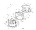
現參考圖3及圖4,接裝板13使來自輸入埠30 (或輸入埠32)之任何下游RF信號S之信號極性及來自輸出埠31 (或分別來自輸出埠33)之任何上游RF信號S之信號極性反轉。接裝板13係較佳地由金屬或塑膠構成之一剛性框架。接裝板13包含具有相對之前側61及後側62之一周邊邊緣60。邊緣60在形狀及大小上對應於背板11之唇部22及面板12之唇部41,使得當背板11、面板12及接裝板13裝配在一起時,唇部22、唇部41及邊緣60彼此齊平且連續。因為邊緣60、唇部22及唇部41係連續的且在形狀及大小上彼此對應,所以背板11、面板12及接裝板13具有一相同周邊外觀尺寸;各板之大小及外部輪廓係相同的,其中各板係相鄰的。此確保在分接頭10之一組裝狀態下之一恰當配合。邊緣60之前側61形成有一周邊通道65以將墊圈24收納且就位於背板11中。同樣地,邊緣60之後側62亦形成有一周邊通道66以將墊圈43收納且就位於面板12中。通道65及66在形狀及大小上彼此對應且分別對應於背板11及面板12中之通道23及42。若干孔或安裝件63形成於接裝板13周圍以允許面板12中之螺栓45穿過背板11之安裝件25且固定於背板11之安裝件25中。當固定於分接頭10之組裝狀態時,墊圈24及43被壓縮且形成不可滲透密封,從而使分接頭10耐候。Referring now to FIGS. 3 and 4, the
接裝板13包含一中間平面印刷電路板64,該中間平面印刷電路板64跨接裝板13之頂部延伸且裝配於前側61與後側62之間。兩個插座70及71自印刷電路板64朝向前側61突出,且兩個端子柱72及73自印刷電路板64朝向後側62突出。相對於邊緣60及唇部41,插座70及71在位置上對應於面板12上之插座53及54,使得當接裝板13施用於背板11時,插座70及71分別對應於,互補於,且適貼地收納端子柱35及36。類似地,相對於邊緣60及唇部22,端子柱72及73在位置上對應於背板11上之端子柱35及36,使得當接裝板13施用於面板12時,端子柱72及73分別對應於插座53及54,互補於插座53及54,且適貼地收納於插座53及54中。因而,當背板11、面板12及接裝板13處於組裝狀態時,端子柱35就位於插座70中,端子柱36就位於插座71中,端子柱72就位於插座53且端子柱73就位於插座54中,各就位連接在各自端子柱與插座對之間建立電連續性。此使背板11及面板12交叉耦合;而在無接裝板13之情況下,端子柱35及36將與同側插座53及54電連接,接裝板13分別電耦合端子柱35及36與相對側插座54及53。此係影響信號S與分接頭信號T之間的極性反轉之因素。
接裝板13包含一電路74,該電路74使分接頭信號T之極性相對於信號S之極性反轉。如在觀看圖3及圖4兩者時可見,來自插座70之電路74連接至端子柱73,且來自插座71之電路74連接至端子柱72。此在信號S到達面板12之前使信號S之極性反轉而不改變背板11之極性。換言之,此結構有效地使面板12及其上之分接頭埠50之極性相對於背板11及其上之埠30至33反轉。例如,當自輸入埠30至輸出埠31之下游RF信號S到達插座53及54時,藉由接裝板13使該下游RF信號S之極性反轉。The
在面板12固定至接裝板13之後,傳輸至用戶或自用戶傳輸之信號之極性不再相對於其在前端或用戶處之原始極性顛倒,使得分接頭10以正確極性操作。例如,當信號S沿硬線載送且載送至一節點分裂下游之輸入埠30時,信號極性首先在節點分裂處顛倒。接著,接裝板13再次使「顛倒」信號S之信號極性反轉,由此將一正確且準確之信號極性提供至面板12上之印刷電路板52。藉由安裝接裝板13,傳入信號S之顛倒方向性恢復至其原始前端極性,且載送至用戶或自用戶載送之分接頭信號T維持其原始或前端極性。因而,分接頭10下游之CATV裝置以正確且經校正之極性操作。After the
上文完整地且清楚地描述一較佳實施例以便使得熟習此項技術者能夠理解、製造及使用該較佳實施例。熟習此項技術者將認知,在不脫離本發明之精神之情況下,可對上文描述進行修改,且一些實施例僅包含彼等所描述元件及特徵或其子組。在修改不脫離本發明之精神的範圍內,其等意欲於包含於本發明之範疇內。A preferred embodiment has been described completely and clearly above to enable those skilled in the art to understand, make, and use the preferred embodiment. Those skilled in the art will recognize that modifications may be made to the above description without departing from the spirit of the invention, and that some embodiments include only their described elements and features, or subsets thereof. Modifications to the extent that they do not depart from the spirit of the present invention are intended to be included within the scope of the present invention.
10‧‧‧通訊分接頭11‧‧‧背板12‧‧‧面板13‧‧‧接裝板20‧‧‧背部21‧‧‧側壁22‧‧‧唇部23‧‧‧通道24‧‧‧墊圈25‧‧‧安裝件30‧‧‧輸入埠31‧‧‧輸出埠32‧‧‧輸入埠33‧‧‧輸出埠34‧‧‧內部35‧‧‧端子柱36‧‧‧端子柱40‧‧‧背部41‧‧‧唇部42‧‧‧通道43‧‧‧墊圈44‧‧‧安裝件45‧‧‧螺栓50‧‧‧分接頭埠51‧‧‧內面52‧‧‧印刷電路板53‧‧‧插座54‧‧‧插座60‧‧‧邊緣61‧‧‧前側62‧‧‧後側63‧‧‧孔或安裝件64‧‧‧中間平面印刷電路板65‧‧‧通道66‧‧‧通道70‧‧‧插座71‧‧‧插座72‧‧‧端子柱73‧‧‧端子柱74‧‧‧電路S‧‧‧有線電視(CATV)信號T‧‧‧分接頭信號10‧‧‧Communication tap11‧‧‧
參考圖式:圖1及圖2係一極性反轉通訊分接頭之後透視圖及前透視圖;及圖3及圖4係圖1之分接頭之分解後透視圖及前透視圖。Reference pattern:1 and 2 are rear and front perspective views of a polarity-reversed communication tap; and3 and 4 are exploded rear and front perspective views of the tap of FIG. 1 .
10‧‧‧通訊分接頭10‧‧‧Communication tap
11‧‧‧背板11‧‧‧Backplane
12‧‧‧面板12‧‧‧Panel
13‧‧‧接裝板13‧‧‧Adapter plate
30‧‧‧輸入埠30‧‧‧Input port
31‧‧‧輸出埠31‧‧‧Output port
S‧‧‧有線電視(CATV)信號S‧‧‧Cable TV (CATV) signal
Claims (17)
Translated fromChineseApplications Claiming Priority (2)
| Application Number | Priority Date | Filing Date | Title |
|---|---|---|---|
| US201762566837P | 2017-10-02 | 2017-10-02 | |
| US62/566,837 | 2017-10-02 |
Publications (2)
| Publication Number | Publication Date |
|---|---|
| TW201933863A TW201933863A (en) | 2019-08-16 |
| TWI757552Btrue TWI757552B (en) | 2022-03-11 |
Family
ID=65896809
Family Applications (1)
| Application Number | Title | Priority Date | Filing Date |
|---|---|---|---|
| TW107134871ATWI757552B (en) | 2017-10-02 | 2018-10-02 | Polarity-inverting telecommunication tap |
Country Status (3)
| Country | Link |
|---|---|
| US (1) | US10312607B2 (en) |
| TW (1) | TWI757552B (en) |
| WO (1) | WO2019070615A1 (en) |
Families Citing this family (6)
| Publication number | Priority date | Publication date | Assignee | Title |
|---|---|---|---|---|
| WO2018089475A1 (en) | 2016-11-09 | 2018-05-17 | Commscope Technologies Llc | Polarity switching hybrid interface |
| US11171440B2 (en)* | 2019-03-20 | 2021-11-09 | Aptiv Technologies Limited | Backing plate for mounting and sealing an electrical connector to an intermediate surface |
| US11611181B2 (en)* | 2020-03-04 | 2023-03-21 | Holland Electronics, Llc | Uninterruptable tap |
| US11522324B2 (en)* | 2021-02-03 | 2022-12-06 | Pct International, Inc. | Dual-direction connector interface for cable devices |
| US20240047918A1 (en)* | 2022-08-05 | 2024-02-08 | Charter Communications Operating, Llc | Faceplate assembly for coaxial taps |
| GB2623346A (en)* | 2022-10-13 | 2024-04-17 | Technetix Bv | Face plate for cable tap unit |
Citations (5)
| Publication number | Priority date | Publication date | Assignee | Title |
|---|---|---|---|---|
| US5756935A (en)* | 1995-10-06 | 1998-05-26 | Nextlevel Systems, Inc. | Screwless seizure bypass platform |
| US20020083467A1 (en)* | 2000-12-27 | 2002-06-27 | Philips Electronics North America Corp. | DVB-ASI signal inverting adapter and system |
| US20040189806A1 (en)* | 2003-03-24 | 2004-09-30 | Berkey Thomas F. | Polarity correction circuit and system incorporating the same |
| US20050078918A1 (en)* | 2003-05-12 | 2005-04-14 | Pct International, Inc. | Line-mounted mini node RF-to-optical converter |
| US20150067755A1 (en)* | 2013-09-04 | 2015-03-05 | Arris Enterprises, Inc. | FFT Tap WiFi Extension Device |
Family Cites Families (4)
| Publication number | Priority date | Publication date | Assignee | Title |
|---|---|---|---|---|
| US5677578A (en)* | 1995-06-13 | 1997-10-14 | Tang; Danny Q. | Cable TV multi-tap with uninterruptible signal/power throughput |
| US6292371B1 (en)* | 1999-10-27 | 2001-09-18 | Toner Cable Equipment, Inc. | Multiple cavity, multiple port modular CATV housing |
| GB2523165B (en) | 2014-02-17 | 2018-09-26 | Technetix Bv | Cable television cable tap device |
| GB2560184B (en) | 2017-03-02 | 2022-03-02 | Technetix Bv | Broadband signal tap |
- 2018
- 2018-10-01USUS16/148,919patent/US10312607B2/enactiveActive
- 2018-10-01WOPCT/US2018/053826patent/WO2019070615A1/ennot_activeCeased
- 2018-10-02TWTW107134871Apatent/TWI757552B/enactive
Patent Citations (5)
| Publication number | Priority date | Publication date | Assignee | Title |
|---|---|---|---|---|
| US5756935A (en)* | 1995-10-06 | 1998-05-26 | Nextlevel Systems, Inc. | Screwless seizure bypass platform |
| US20020083467A1 (en)* | 2000-12-27 | 2002-06-27 | Philips Electronics North America Corp. | DVB-ASI signal inverting adapter and system |
| US20040189806A1 (en)* | 2003-03-24 | 2004-09-30 | Berkey Thomas F. | Polarity correction circuit and system incorporating the same |
| US20050078918A1 (en)* | 2003-05-12 | 2005-04-14 | Pct International, Inc. | Line-mounted mini node RF-to-optical converter |
| US20150067755A1 (en)* | 2013-09-04 | 2015-03-05 | Arris Enterprises, Inc. | FFT Tap WiFi Extension Device |
Also Published As
| Publication number | Publication date |
|---|---|
| WO2019070615A1 (en) | 2019-04-11 |
| US10312607B2 (en) | 2019-06-04 |
| US20190103686A1 (en) | 2019-04-04 |
| TW201933863A (en) | 2019-08-16 |
Similar Documents
| Publication | Publication Date | Title |
|---|---|---|
| TWI757552B (en) | Polarity-inverting telecommunication tap | |
| US6133939A (en) | CATV directional component with signal reversing capability and method | |
| US5850165A (en) | Non-interruptable tap and method | |
| US10931039B2 (en) | Flexible coaxial connector | |
| US6243273B1 (en) | Mini-backplane “T” assembly | |
| RU2550339C1 (en) | Self-contained mobile telecommunication complex | |
| US11522304B2 (en) | Modular circuit board multi-tap | |
| US10784664B2 (en) | Three-piece electronics enclosure | |
| US5892653A (en) | Multi-tap distribution box | |
| US11444870B2 (en) | Circuitry for demarcation devices and methods utilizing same | |
| CN101107754B (en) | Loop plug | |
| US8798411B1 (en) | Switching system for optical fiber connection | |
| WO2016076595A1 (en) | Waveguide slot array antenna | |
| JP3204119U (en) | Cable TV coaxial video network transmitter and its insertion connection socket | |
| US20110103575A1 (en) | High-density splitter/patch telecommunications system | |
| EP4510606A1 (en) | Improvements in or relating to signal tap faceplate alignment | |
| GB2402268A (en) | Positionable cable connection device | |
| CN208255481U (en) | Television transmission cable installation | |
| EP3190669B1 (en) | Connector for a coaxial cable | |
| JP4512256B2 (en) | Electronic device case and amplification device | |
| DK178898B1 (en) | Push-in udtagssystem | |
| US6157273A (en) | Rotatable directional coupler with a tap plate | |
| EP1168854A2 (en) | Modular expandible directional connection board | |
| MXPA00000381A (en) | Catv directional component with signal reversing capability and method | |
| TWM673395U (en) | Hybrid fiber-coaxial network device |