TWI756932B - Thermal imaging apparatus and temperature correction method of thermal imager - Google Patents
Thermal imaging apparatus and temperature correction method of thermal imagerDownload PDFInfo
- Publication number
- TWI756932B TWI756932BTW109140755ATW109140755ATWI756932BTW I756932 BTWI756932 BTW I756932BTW 109140755 ATW109140755 ATW 109140755ATW 109140755 ATW109140755 ATW 109140755ATW I756932 BTWI756932 BTW I756932B
- Authority
- TW
- Taiwan
- Prior art keywords
- thermal
- image
- optical
- thermal image
- distance
- Prior art date
Links
Images


Classifications
- G—PHYSICS
- G01—MEASURING; TESTING
- G01J—MEASUREMENT OF INTENSITY, VELOCITY, SPECTRAL CONTENT, POLARISATION, PHASE OR PULSE CHARACTERISTICS OF INFRARED, VISIBLE OR ULTRAVIOLET LIGHT; COLORIMETRY; RADIATION PYROMETRY
- G01J5/00—Radiation pyrometry, e.g. infrared or optical thermometry
- G01J5/0022—Radiation pyrometry, e.g. infrared or optical thermometry for sensing the radiation of moving bodies
- G01J5/0025—Living bodies
- G—PHYSICS
- G01—MEASURING; TESTING
- G01C—MEASURING DISTANCES, LEVELS OR BEARINGS; SURVEYING; NAVIGATION; GYROSCOPIC INSTRUMENTS; PHOTOGRAMMETRY OR VIDEOGRAMMETRY
- G01C3/00—Measuring distances in line of sight; Optical rangefinders
- G—PHYSICS
- G01—MEASURING; TESTING
- G01J—MEASUREMENT OF INTENSITY, VELOCITY, SPECTRAL CONTENT, POLARISATION, PHASE OR PULSE CHARACTERISTICS OF INFRARED, VISIBLE OR ULTRAVIOLET LIGHT; COLORIMETRY; RADIATION PYROMETRY
- G01J5/00—Radiation pyrometry, e.g. infrared or optical thermometry
- G01J5/02—Constructional details
- G01J5/0275—Control or determination of height or distance or angle information for sensors or receivers
- G—PHYSICS
- G01—MEASURING; TESTING
- G01J—MEASUREMENT OF INTENSITY, VELOCITY, SPECTRAL CONTENT, POLARISATION, PHASE OR PULSE CHARACTERISTICS OF INFRARED, VISIBLE OR ULTRAVIOLET LIGHT; COLORIMETRY; RADIATION PYROMETRY
- G01J5/00—Radiation pyrometry, e.g. infrared or optical thermometry
- G01J5/02—Constructional details
- G01J5/08—Optical arrangements
- G01J5/0806—Focusing or collimating elements, e.g. lenses or concave mirrors
- G—PHYSICS
- G01—MEASURING; TESTING
- G01J—MEASUREMENT OF INTENSITY, VELOCITY, SPECTRAL CONTENT, POLARISATION, PHASE OR PULSE CHARACTERISTICS OF INFRARED, VISIBLE OR ULTRAVIOLET LIGHT; COLORIMETRY; RADIATION PYROMETRY
- G01J5/00—Radiation pyrometry, e.g. infrared or optical thermometry
- G01J2005/0077—Imaging
- G—PHYSICS
- G01—MEASURING; TESTING
- G01J—MEASUREMENT OF INTENSITY, VELOCITY, SPECTRAL CONTENT, POLARISATION, PHASE OR PULSE CHARACTERISTICS OF INFRARED, VISIBLE OR ULTRAVIOLET LIGHT; COLORIMETRY; RADIATION PYROMETRY
- G01J5/00—Radiation pyrometry, e.g. infrared or optical thermometry
- G01J5/48—Thermography; Techniques using wholly visual means
- G01J5/485—Temperature profile
- G—PHYSICS
- G01—MEASURING; TESTING
- G01J—MEASUREMENT OF INTENSITY, VELOCITY, SPECTRAL CONTENT, POLARISATION, PHASE OR PULSE CHARACTERISTICS OF INFRARED, VISIBLE OR ULTRAVIOLET LIGHT; COLORIMETRY; RADIATION PYROMETRY
- G01J5/00—Radiation pyrometry, e.g. infrared or optical thermometry
- G01J5/80—Calibration
Landscapes
- Physics & Mathematics (AREA)
- General Physics & Mathematics (AREA)
- Spectroscopy & Molecular Physics (AREA)
- Electromagnetism (AREA)
- Engineering & Computer Science (AREA)
- Radar, Positioning & Navigation (AREA)
- Remote Sensing (AREA)
- Radiation Pyrometers (AREA)
Abstract
Description
Translated fromChinese本發明係關於一種熱像設備,特別係關於一種具有溫度校正功能的熱像設備。The present invention relates to a thermal imaging device, in particular to a thermal imaging device with a temperature correction function.
因應新型冠狀肺炎(COVID-19)在全球大流行的狀況,各國機場及其他公共場所皆設有體溫篩檢之防疫機制。相較於人工手動量測,透過熱影像篩檢可以有效減少人流量過多的量測時間。然而,因熱輻射在介質空間中會有衰退的問題,熱像儀所測之標的物溫度會因標的物與熱像儀的距離遠近而有所差異,進而造成體溫量測之誤差。In response to the global pandemic of the new type of coronavirus (COVID-19), airports and other public places in various countries have established an epidemic prevention mechanism for body temperature screening. Compared with manual measurement, thermal image screening can effectively reduce the measurement time of excessive human traffic. However, due to the problem of thermal radiation decay in the medium space, the temperature of the object measured by the thermal imager will be different due to the distance between the object and the thermal imager, which will cause errors in body temperature measurement.
鑒於上述,本發明提供一種熱像設備及熱像儀之溫度校正方法。In view of the above, the present invention provides a thermal imaging device and a temperature correction method for a thermal imaging camera.
依據本發明一實施例的熱像設備,用於量測監控區域內的至少一標的物之溫度,且包含熱像儀、光學攝像器及運算處理裝置,其中運算處理裝置連接於熱像儀及光學攝像器。熱像儀用於對監控區域擷取熱影像。光學攝像器用於對該監控區域擷取多筆光學影像。運算處理裝置經配置以依據熱影像及所述多筆光學影像中對應於標的物之區塊之位置,決定所述多筆光學影像中之一與熱影像為同步,依據熱影像及決定的光學影像執行運算,取得標的物與熱像設備間之量測距離,以及依據量測距離及熱影像,執行校正運算以取得標的物之校正溫度值。The thermal imaging device according to an embodiment of the present invention is used to measure the temperature of at least one object in the monitoring area, and includes a thermal imaging camera, an optical camera and an arithmetic processing device, wherein the arithmetic processing device is connected to the thermal imaging camera and the arithmetic processing device. Optical camera. The thermal imager is used to capture thermal images of the surveillance area. The optical camera is used for capturing multiple optical images of the monitoring area. The arithmetic processing device is configured to determine that one of the multiple optical images is synchronized with the thermal image according to the thermal image and the position of the block corresponding to the target object in the multiple optical images, and based on the thermal image and the determined optical image The image performs an operation to obtain the measured distance between the target object and the thermal imaging device, and performs a correction operation to obtain the corrected temperature value of the target object according to the measured distance and the thermal image.
依據本發明一實施例的熱像儀之溫度校正方法,適用於熱像設備以取得監控區域內的至少一標的物之溫度。所述溫度校正方法包含:取得監控區域的熱影像;取得監控區域的多筆光學影像;依據熱影像及所述多筆光學影像中對應於標的物之區塊之位置,決定所述多筆光學影像中之一與熱影像為同步;依據熱影像及決定的光學影像執行運算,取得標的物與熱像設備間之量測距離;以及依據量測距離及熱影像,執行校正運算以取得標的物之校正溫度值。The temperature calibration method for a thermal imager according to an embodiment of the present invention is suitable for thermal imaging equipment to obtain the temperature of at least one target object in a monitoring area. The temperature correction method includes: obtaining a thermal image of the monitoring area; obtaining multiple optical images of the monitoring area; determining the multiple optical images according to the thermal image and the position of the block corresponding to the target object in the multiple optical images One of the images is synchronized with the thermal image; perform calculation based on the thermal image and the determined optical image to obtain the measurement distance between the target object and the thermal imaging device; and perform correction calculation to obtain the target object according to the measurement distance and the thermal image The corrected temperature value.
藉由上述結構,本案所揭示的熱像設備及熱像儀之溫度校正方法,設置熱像儀與光學攝像器並搭配特殊運算,可以不需設置測距儀便能取得待測物與熱像設備之間的距離以進行溫度校正運算,藉此降低設備成本。透過特殊之決定同步熱影像與光學影像的方式,本案所揭示的熱像設備及熱像儀之溫度校正方法可以取得在最相近之時間點所拍攝的熱影像及光學影像來進行後續的距離計算及溫度校正運算,進而提高提升溫度估算的準確度。With the above structure, the thermal imaging equipment and the temperature calibration method of the thermal imaging camera disclosed in this case can obtain the object to be measured and the thermal image without setting up a rangefinder by setting up a thermal imaging camera and an optical camera and matching with special operations. The distance between the devices can be used to perform temperature correction calculations, thereby reducing the cost of the device. Through the special method of synchronizing thermal image and optical image, the thermal image equipment and the temperature correction method of thermal imager disclosed in this case can obtain the thermal image and optical image taken at the closest time point for subsequent distance calculation. and temperature correction operations, thereby improving the accuracy of temperature estimation.
以上之關於本揭露內容之說明及以下之實施方式之說明係用以示範與解釋本發明之精神與原理,並且提供本發明之專利申請範圍更進一步之解釋。The above description of the present disclosure and the following description of the embodiments are used to demonstrate and explain the spirit and principle of the present invention, and provide further explanation of the scope of the patent application of the present invention.
以下在實施方式中詳細敘述本發明之詳細特徵以及優點,其內容足以使任何熟習相關技藝者了解本發明之技術內容並據以實施,且根據本說明書所揭露之內容、申請專利範圍及圖式,任何熟習相關技藝者可輕易地理解本發明相關之目的及優點。以下之實施例係進一步詳細說明本發明之觀點,但非以任何觀點限制本發明之範疇。The detailed features and advantages of the present invention are described in detail in the following embodiments, and the content is sufficient to enable any person skilled in the relevant art to understand the technical content of the present invention and implement it accordingly, and according to the content disclosed in this specification, the scope of the patent application and the drawings , any person skilled in the related art can easily understand the related objects and advantages of the present invention. The following examples further illustrate the viewpoints of the present invention in detail, but do not limit the scope of the present invention in any viewpoint.
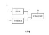
本發明提出一種熱像設備,可以量測監控區域內的至少一標的物的溫度,例如係活體或其他特定物體之溫度,且可以運算熱像設備與標的物之距離以校正測得溫度,藉此取得更貼近真實溫度的數值。請參考圖1,圖1為依據本發明一實施例所繪示的熱像設備1的功能方塊圖。如圖1所示,熱像設備1包含熱像儀11、光學攝像器13及運算處理裝置15,其中運算處理裝置15透過有線或無線的方式連接於熱像儀11及光學攝像器13。熱像儀11又稱紅外線熱成像儀,用於對監控區域擷取熱影像。光學攝像器13例如為彩色(RGB)攝影機,用於對監控區域擷取多筆光學影像。The present invention provides a thermal imaging device, which can measure the temperature of at least one target object in the monitoring area, such as the temperature of a living body or other specific objects, and can calculate the distance between the thermal imaging device and the target object to correct the measured temperature. This obtains a value closer to the real temperature. Please refer to FIG. 1 , which is a functional block diagram of a
運算處理裝置15包含中央處理器、微控制器、可編程邏輯控制器等處理元件,可以經配置以執行:依據熱影像及所述多筆光學影像中對應於標的物之區塊之位置,決定所述多筆光學影像中之一與熱影像為同步;依據熱影像及決定的光學影像執行運算,以取得標的物與熱像設備之間的距離(量測距離);以及依據量測距離及熱影像,執行校正運算以取得標的物的校正溫度值。其中詳細的運算內容將於後描述。另外,運算處理裝置15取得校正溫度值後可以透過使用者介面或通訊介面輸出校正溫度值,或是將校正溫度值與指示體溫異常的預設閾值比較,再將比較結果透過使用者介面或通訊介面輸出。The
特別來說,藉由熱像儀11與光學攝像器13的共同運作以及運算處理裝置15依據熱影像及光學影像所執行之特殊運算,熱像設備1可以取得標的物與熱像設備之間的距離以進行後續溫度校正運算而不需設置測距儀,藉此降低設備成本。另外,一般而言,熱像儀11的幀率(Frames per second,FPS)會低於光學攝像器13的幀率(例如1:6),也就是說,兩硬體的影像資料間存在一對多的映射關係,而同一時間區間內取得的光學影像中可能存在與熱影像不同步者。當在用以計算標的物與熱像設備之間距的熱影像及光學影像的拍攝時間中標的物有所位移時,距離的計算將有所誤差,致使後續之溫度校正發生錯誤。藉由運算處理裝置15執行依據標的物在影像中的位置來決定熱影像所對應的光學影像,熱像設備1可以取得同步程度最高之熱影像及光學影像來進行後續的距離計算及溫度校正運算,藉此避免上述取像不同步所產生的問題,進而提升溫度估算的準確度。In particular, through the joint operation of the
圖1繪示熱像設備1示例性的功能方塊圖。進一步地,本發明亦提出熱像設備1之取像元件在空間上的特殊排列。請一併參考圖1、圖2A及圖2B,其中圖2A係依據本發明一實施例所繪示的熱像設備1的前視示意圖,圖2B則係依據本發明另一實施例所繪示的熱像設備1的前視示意圖。於圖2A的實施例中,熱像儀11與光學攝像器13為垂直排列,進一步來說,熱像儀11之感測器與光學攝像器13之鏡頭為垂直排列。其中,所謂垂直排列係指熱像儀11之感測器與光學攝像器13之鏡頭的中心連線方向大致平行於重力方向,具體來說,熱像儀11之感測器與光學攝像器13之鏡頭之中心連線方向可以與重力方向之間可以具有±45度以內之容忍角度差。而於圖2B的實施例中,熱像儀11與光學攝像器13為水平排列,進一步來說,熱像儀11之感測器與光學攝像器13之鏡頭為水平排列。其中,所謂水平排列係指熱像儀11之感測器與光學攝像器13之鏡頭的中心連線方向大致垂直於重力方向,具體來說,熱像儀11之感測器與光學攝像器13之鏡頭之中心連線方向可以與垂直於重力方向的水平線之間可以具有±45度以內之容忍角度差。FIG. 1 is an exemplary functional block diagram of a
藉由上列排列方式,運算處理裝置15便可基於熱像儀11與光學攝像器13之視差來對熱影像及對應的光學影像上的標的物位置進行運算,以取得標的物與熱像設備1間之距離,其中詳細的運算內容將於後描述。於此要特別說明的是,圖2A及圖2B僅示例性地繪示熱像設備1之熱像儀11與光學攝像器13為垂直排列或水平排列,非意圖限制熱像儀11與光學攝像器13的上下關係或左右關係,亦非意圖限制熱像儀11及光學攝像器13的尺寸或形狀。Through the above arrangement, the
本發明亦提出一種熱像儀之溫度校正方法,適用於熱像設備1。請一併參考圖1及圖3,其中圖3係依據本發明一實施例所繪示的熱像儀之溫度校正方法的流程圖。如圖3所示,溫度校正方法包含步驟S1,取得監控區域的熱影像及多筆光學影像;步驟S3,依據熱影像及所述多筆光學影像中對應於標的物之區塊之位置,決定所述多筆光學影像中之一與熱影像為同步;步驟S5,依據熱影像及決定的光學影像執行運算,取得標的物與熱像設備間之量測距離;以及步驟S7,依據量測距離及熱影像,執行校正運算以取得標的物之校正溫度值。The present invention also provides a temperature correction method for a thermal imaging camera, which is suitable for the
於步驟S1中,熱像設備1的運算處理裝置15從熱像儀11取得一熱影像並從光學攝像器13取得多筆光學影像。進一步來說,熱像設備1在運作時,熱像儀11對監控區域以第一幀率持續地擷取熱影像,光學攝像器13對監控區域以第二幀率持續地擷取光學影像,運算處理裝置15便依據第一幀率與第二幀率之比來決定取用之熱影像與光學影像的數量比。舉例來說,若第一幀率為5fps而第二幀率為30fps,運算處理裝置15每取1筆熱影像便會取6筆光學影像以進行後續步驟S3之對應關係的判斷。In step S1 , the
另外,運算處理裝置15所取用之熱影像的產生時間點(即熱像儀11拍攝而產生此熱影像的時間點)可以相同或近似於所取用之光學影像中第一筆產生的光學影像的產生時間點(即光學攝像器13拍攝而產生此光學影像的時間點),可以相同或近似於所取用之光學影像中最後一筆產生的光學影像的產生時間點,或可以介於第一筆產生的光學影像與最後一筆產生的光學影像的產生時間點之間,其中以中間時間點為佳。In addition, the generation time point of the thermal image acquired by the computing processing device 15 (that is, the time point at which the thermal image is captured by the thermal imager 11 ) may be the same as or similar to the optical image generated by the first stroke in the acquired optical image. The generation time point of the image (that is, the time point at which the optical image is captured by the optical camera 13 ) may be the same as or similar to the generation time point of the optical image generated by the last stroke of the used optical image, or may be between the first and second optical images. Between the generation time point of the optical image generated by one stroke and the optical image generated by the last stroke, the middle time point is preferred.
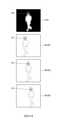
於步驟S3中,運算處理裝置15依據熱影像及所述多筆光學影像中對應於標的物之區塊之位置,決定所述多筆光學影像中之一與熱影像為同步。於此要特別說明的是,所謂同步係指在同一時間點或最相近之時間點所產生的熱影像及光學影像。進一步來說明步驟S3的實施方式,請參考圖4A及4B,其中圖4A係依據本發明一實施例所繪示的熱像儀之溫度校正方法中決定同步於熱影像之光學影像的運作示意圖,圖4B則係依據本發明另一實施例所繪示的熱像儀之溫度校正方法中決定同步於熱影像之光學影像的運作示意圖。In step S3, the
於圖4A所示的實施例中,運算處理裝置15所執行之依據熱影像及所述多筆光學影像中對應於標的物之區塊之位置,決定所述多筆光學影像中之一與熱影像為同步的步驟(圖3之步驟S3)包含:分別計算每一光學影像RGB1~RGB3中對應於標的物之區塊之座標以及熱影像TH1中對應於標的物之區塊之座標之距離,以及決定光學影像RGB1~RGB3中之一具有最小距離者與熱影像TH1為同步,其中所述距離是沿x軸方向或y軸方向計算。圖4A示例性地繪示以活體作為標的物,並以影像中對應於活體頭部之區塊的幾何中心座標來進行距離的計算。詳細來說,運算處理裝置15可以取得熱影像TH1中對應於活體頭部之區塊的幾何中心P0之座標,取得光學影像RGB1~RGB3中對應於活體頭部之區塊的幾何中心P1~P3之座標,其中幾何中心P0及P1~P3之座標其座標系相同,並分別計算幾何中心P1~P3之座標與幾何中心P0之座標之間的距離。進一步來說,對於圖2A所示之取像元件為垂直排列的熱像設備1而言,座標間的距離係沿x軸方向計算,也就是分別計算幾何中心P1~P3的x座標與幾何中心P0的x座標之間的差,其即為前述距離;對於圖2B所示之取像元件為水平排列的熱像設備1而言,座標間的距離係沿y軸方向計算,也就是分別計算幾何中心P1~P3的y座標與幾何中心P0的y座標之間的差,其即為前述距離。接著,運算處理裝置15會決定光學影像RGB1~RGB3中之一具有最小距離最者(即光學影像RGB2)與熱影像TH1為同步。In the embodiment shown in FIG. 4A , the
舉例來說,運算處理裝置15可以辨識熱影像TH1中具有普遍活體溫度(例如攝氏34~40度)的熱團塊,並將熱團塊之頂部部分視為對應於活體頭部之區塊,且可以藉由臉部定位(例如膚色辨識、五官特徵辨識或其他AI辨識)辨識光學影像RGB1~RGB3中對應於活體頭部之區塊。於其他實施例中,運算處理裝置15亦可設定為以對應於活體之其他部位之區塊的座標來計算距離。另外要特別說明的是,圖4A示例性地繪示3筆光學影像RGB1~RGB3,並非意圖限制運算處理裝置15取用來與熱影像比對之光學影像的數量。For example, the
於圖4B所示的實施例中,運算處理裝置15所執行之依據熱影像及所述多筆光學影像中對應於標的物之區塊之位置,決定所述多筆光學影像中之一與熱影像為同步的步驟(圖3之步驟S3)包含:取得熱影像TH2中對應於活體之頭部的座標(第一座標),取得每一光學影像RGB4中對應於活體之頭部的座標(第二座標),計算兩座標的誤差值,以及決定光學影像RGB4中之一具有最小誤差值者與熱影像TH2為同步,其中所述誤差值是沿x軸方向或y軸方向計算。詳細來說,運算處理裝置15可以先對熱影像TH2進行特定溫度範圍內(例如攝氏34~40度)之熱團塊的擷取處理,以產生包含多個熱團塊(具有幾何中心A1~A6)的熱影像TH2’,再篩選出對應於活體頭部的熱團塊(具有幾何中心A1~A3)的座標。舉例來說,運算處理裝置15可以將活體頭部通常在畫面中所呈現之y座標作為篩選條件。接著,運算處理裝置將熱影像TH2’中對應於活體頭部的熱團塊(具有幾何中心A1~A3)的座標來與光學影像RGB4中對應於活體頭部的區塊(具有幾何中心B1~B3)的座標進行誤差值的運算。In the embodiment shown in FIG. 4B , the
進一步來說,對於圖2A所示之取像元件為垂直排列的熱像設備1而言,誤差值是沿x軸方向計算,其中誤差值之運算式可以為:


在執行圖3之步驟S3以取得同步之熱影像及光學影像後,運算處理裝置15續行步驟S5以計算活體與熱像設備1之間的距離。如前所述,於步驟S5中,運算處理裝置15依據熱影像及光學影像執行運算,取得標的物與熱像設備間之量測距離。進一步來說,運算處理裝置15可以依據標的物在熱影像中的成像位置、標的物在光學影像中的成像位置之x或y座標、熱像儀11的焦距、光學攝像器13的焦距以及熱像儀11的感測器與光學攝像器13的鏡頭之間的距離,計算出標的物與熱像設備間之量測距離。After performing step S3 in FIG. 3 to obtain the synchronized thermal image and optical image, the
更進一步來說,影像中標的物的成像位置之y座標可以由運算處理裝置15計算影像中對應於標的物的頭頂之位置或頭部幾何中心與影像的上邊緣之間的距離而得,影像中標的物的成像位置之x座標則可以由運算處理裝置15計算影像中對應於標的物的頭頂之位置或頭部幾何中心與影像的側邊緣之間的距離而得,熱像儀11/光學攝像器13的焦距可以預存於運算處理裝置15的記憶體或外部資料庫中或由運算處理裝置15對熱影像/光學影像進行影像校正以獲得;熱像儀11的感測器與光學攝像器13的鏡頭之間的距離可以預存於運算處理裝置15的記憶體或外部資料庫中;而計算量測距離所用之運算式可以為:


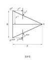
上述運算式可以基於相似三角形原理而推得。請參考圖5,圖5係依據本發明一實施例所繪示的熱像儀之溫度校正方法中取得待測物與熱像設備間之量測距離的運算原理示意圖。圖5示例性地繪示了熱像儀鏡心


上述圖5所示之距離計算方式適用於如圖2A所示之取像元件為垂直排列之熱像設備1,而對於熱像儀11之感測器與光學攝像器13之鏡頭之連線與垂直線之間具有小於容忍角度差之角度差的熱像設備1,運算處理裝置15可以先對熱影像及光學影像進行影像校正以補償所述角度差,再執行上列實施例所述之距離計算。至於如圖2B所示之取像元件為水平排列的熱像設備1,其適用之距離計算方式同理於圖5之實施方式,差別在於原基於y座標之距離計算改為基於x座標之距離計算。進一步來說,所用之計算量測距離的運算式可以為:


於步驟S7中,運算處理裝置15依據量測距離及熱影像,執行校正運算以取得標的物之校正溫度值。進一步來說,運算處理裝置15判斷熱影像具有對應於標的物的一感測溫度值,依據量測距離查找距離溫度校正表以取得一補償溫度值,再將感測溫度值與補償溫度值進行運算(例如加法)以取得校正溫度值。距離溫度校正表可儲存於運算處理裝置15的記憶體中或可從外部資料庫取得。下列表1示例性地呈現距離溫度校正表。舉例來說,當熱影像所具有之對應於標的物的感測溫度值為攝氏36.1度且標的物與熱像設備1之間的距離為1.5公尺,則經運算處理裝置15執行校正運算而取得之校正溫度值為36.6度。In step S7, the
表1
藉由上述結構,本案所揭示的熱像設備及熱像儀之溫度校正方法,設置熱像儀與光學攝像器並搭配特殊運算,可以不需設置測距儀便能取得待測物與熱像設備之間的距離以進行溫度校正運算,藉此降低成本。透過特殊之決定同步熱影像與光學影像的方式,本案所揭示的熱像設備及熱像儀之溫度校正方法可以取得在最相近之時間點所拍攝的熱影像及光學影像來進行後續的距離計算及溫度校正運算,進而提高提升溫度估算的準確度。With the above structure, the thermal imaging equipment and the temperature calibration method of the thermal imaging camera disclosed in this case can obtain the object to be measured and the thermal image without setting up a rangefinder by setting up a thermal imaging camera and an optical camera and matching with special operations. The distance between devices to perform temperature correction calculations, thereby reducing costs. Through the special method of synchronizing thermal image and optical image, the thermal image equipment and the temperature correction method of thermal imager disclosed in this case can obtain the thermal image and optical image taken at the closest time point for subsequent distance calculation. and temperature correction operations, thereby improving the accuracy of temperature estimation.
雖然本發明以前述之實施例揭露如上,然其並非用以限定本發明。在不脫離本發明之精神和範圍內,所為之更動與潤飾,均屬本發明之專利保護範圍。關於本發明所界定之保護範圍請參考所附之申請專利範圍。Although the present invention is disclosed in the foregoing embodiments, it is not intended to limit the present invention. Changes and modifications made without departing from the spirit and scope of the present invention belong to the scope of patent protection of the present invention. For the protection scope defined by the present invention, please refer to the attached patent application scope.
1:熱像設備 11:熱像儀 13:光學攝像器 15:運算處理裝置 S1~S7:步驟 TH1、TH2、TH2’:熱影像 RGB1~RGB4:光學影像 P0、P1~P3、A1~A6、B1~B3:幾何中心 r1~r3:半徑
圖1係依據本發明一實施例所繪示的熱像設備的功能方塊圖。 圖2A係依據本發明一實施例所繪示的熱像設備的前視示意圖。 圖2B係依據本發明另一實施例所繪示的熱像設備的前視示意圖。 圖3係依據本發明一實施例所繪示的熱像儀之溫度校正方法的流程圖。 圖4A係依據本發明一實施例所繪示的熱像儀之溫度校正方法中決定同步於熱影像之光學影像的運作示意圖。 圖4B係依據本發明另一實施例所繪示的熱像儀之溫度校正方法中決定同步於熱影像之光學影像的運作示意圖。 圖5係依據本發明一實施例所繪示的熱像儀之溫度校正方法中取得待測物與熱像設備間之量測距離的運算原理示意圖。FIG. 1 is a functional block diagram of a thermal imaging device according to an embodiment of the present invention. 2A is a schematic front view of a thermal imaging device according to an embodiment of the present invention. 2B is a schematic front view of a thermal imaging device according to another embodiment of the present invention. FIG. 3 is a flowchart of a temperature calibration method of a thermal imager according to an embodiment of the present invention. 4A is a schematic diagram of the operation of determining the optical image synchronized with the thermal image in the temperature calibration method of the thermal imager according to an embodiment of the present invention. 4B is a schematic diagram of the operation of determining the optical image synchronized with the thermal image in the temperature calibration method of the thermal imager according to another embodiment of the present invention. FIG. 5 is a schematic diagram of the operation principle of obtaining the measurement distance between the object to be measured and the thermal imaging device in the temperature calibration method of the thermal imager according to an embodiment of the present invention.
1:熱像設備1: Thermal imaging equipment
11:熱像儀11: Thermal imager
13:光學攝像器13: Optical camera
15:運算處理裝置15: Arithmetic processing device
Claims (16)
Translated fromChinese


Priority Applications (3)
| Application Number | Priority Date | Filing Date | Title |
|---|---|---|---|
| TW109140755ATWI756932B (en) | 2020-11-20 | 2020-11-20 | Thermal imaging apparatus and temperature correction method of thermal imager |
| CN202110067402.3ACN114593832B (en) | 2020-11-20 | 2021-01-19 | Thermal imaging device and temperature correction method of thermal imager |
| US17/217,849US11754446B2 (en) | 2020-11-20 | 2021-03-30 | Thermal imaging apparatus and temperature calibration method of thermal imaging apparatus |
Applications Claiming Priority (1)
| Application Number | Priority Date | Filing Date | Title |
|---|---|---|---|
| TW109140755ATWI756932B (en) | 2020-11-20 | 2020-11-20 | Thermal imaging apparatus and temperature correction method of thermal imager |
Publications (2)
| Publication Number | Publication Date |
|---|---|
| TWI756932Btrue TWI756932B (en) | 2022-03-01 |
| TW202221644A TW202221644A (en) | 2022-06-01 |
Family
ID=81658064
Family Applications (1)
| Application Number | Title | Priority Date | Filing Date |
|---|---|---|---|
| TW109140755ATWI756932B (en) | 2020-11-20 | 2020-11-20 | Thermal imaging apparatus and temperature correction method of thermal imager |
Country Status (3)
| Country | Link |
|---|---|
| US (1) | US11754446B2 (en) |
| CN (1) | CN114593832B (en) |
| TW (1) | TWI756932B (en) |
Families Citing this family (2)
| Publication number | Priority date | Publication date | Assignee | Title |
|---|---|---|---|---|
| US12182990B2 (en)* | 2022-05-13 | 2024-12-31 | GM Global Technology Operations LLC | Battery component inspection based on optical and thermal imaging |
| TWI817798B (en)* | 2022-10-31 | 2023-10-01 | 財團法人工業技術研究院 | Method for evaluating tool health with the temperature rising |
Citations (3)
| Publication number | Priority date | Publication date | Assignee | Title |
|---|---|---|---|---|
| CN107067470A (en)* | 2017-04-05 | 2017-08-18 | 东北大学 | Portable three-dimensional reconstruction of temperature field system based on thermal infrared imager and depth camera |
| US10116885B2 (en)* | 2015-04-05 | 2018-10-30 | Hema Imaging Llc | Systems and approaches for repeated thermal imaging determinations |
| CN111412994A (en)* | 2020-04-24 | 2020-07-14 | 西安理工大学 | An Enhancement System for Improving the Temperature Measurement Accuracy of Thermal Imager |
Family Cites Families (23)
| Publication number | Priority date | Publication date | Assignee | Title |
|---|---|---|---|---|
| US7924312B2 (en) | 2008-08-22 | 2011-04-12 | Fluke Corporation | Infrared and visible-light image registration |
| JP5818451B2 (en)* | 2011-02-09 | 2015-11-18 | キヤノン株式会社 | Imaging apparatus and control method |
| US8970704B2 (en) | 2011-06-07 | 2015-03-03 | Verizon Patent And Licensing Inc. | Network synchronized camera settings |
| JP2013074466A (en)* | 2011-09-28 | 2013-04-22 | Jvc Kenwood Corp | Moving image capturing system, moving image analysis device, moving image analysis method, and computer program |
| CN105102947B (en) | 2012-11-19 | 2018-05-29 | 卡兹欧洲公司 | It should be with the contactless clinical thermometer of compensation function with distance perspective |
| CN103402109B (en)* | 2013-07-31 | 2015-07-08 | 上海交通大学 | Detecting and ensuring method of frame synchronization between left and right viewpoints in 3D video |
| US11297264B2 (en)* | 2014-01-05 | 2022-04-05 | Teledyne Fur, Llc | Device attachment with dual band imaging sensor |
| CN104063867B (en)* | 2014-06-27 | 2017-02-08 | 浙江宇视科技有限公司 | Multi-camera video synchronization method and multi-camera video synchronization device |
| TWI630377B (en)* | 2017-04-18 | 2018-07-21 | 亞迪電子股份有限公司 | Thermal image detecting device |
| CN107395965B (en)* | 2017-07-14 | 2019-11-29 | 维沃移动通信有限公司 | A kind of image processing method and mobile terminal |
| CN107941342A (en) | 2017-10-19 | 2018-04-20 | 上海电力学院 | Comprehensive distance and the electric inspection process robot infrared temperature measurement apparatus and method at visual angle |
| TWI704502B (en) | 2018-06-08 | 2020-09-11 | 晟風科技股份有限公司 | Thermal imager with temperature compensation function for distance and its temperature compensation method |
| CN110657803B (en)* | 2018-06-28 | 2021-10-29 | 深圳市优必选科技有限公司 | Robot positioning method, device and storage device |
| CN111464978A (en)* | 2019-01-22 | 2020-07-28 | 岳秀兰 | Vehicle remote driving system established by connection of primary wireless equipment and secondary wireless equipment through Internet of things |
| CN109920185A (en)* | 2019-04-16 | 2019-06-21 | 中科九度(北京)空间信息技术有限责任公司 | One kind merging the mobile mesh calibration method of detection with video data based on millimetre-wave radar |
| CN111223225A (en) | 2020-02-11 | 2020-06-02 | 厦门瑞为信息技术有限公司 | Detection passing system integrating temperature measurement and face recognition gate machine partner |
| CN111339951A (en) | 2020-02-26 | 2020-06-26 | 北京迈格威科技有限公司 | Body temperature measuring method, device and system |
| CN111426394A (en) | 2020-04-16 | 2020-07-17 | 成都立鑫新技术科技有限公司 | Body temperature detection system and method for simultaneously detecting multiple persons |
| CN111551191B (en)* | 2020-04-28 | 2022-08-09 | 浙江商汤科技开发有限公司 | Sensor external parameter calibration method and device, electronic equipment and storage medium |
| WO2021226554A1 (en)* | 2020-05-08 | 2021-11-11 | Flir Systems Ab | Dual-band temperature detection systems and methods |
| CN111623881A (en)* | 2020-05-21 | 2020-09-04 | 平安国际智慧城市科技股份有限公司 | Double-optical-camera temperature measurement method based on image processing and related equipment |
| KR20220036418A (en)* | 2020-09-14 | 2022-03-23 | 주식회사 케이티 | Apparatus, method and computer program for correcting temperature of object |
| CN114646394A (en)* | 2020-12-17 | 2022-06-21 | 财团法人工业技术研究院 | Thermal image-based temperature measurement correction method and thermal image device |
- 2020
- 2020-11-20TWTW109140755Apatent/TWI756932B/enactive
- 2021
- 2021-01-19CNCN202110067402.3Apatent/CN114593832B/enactiveActive
- 2021-03-30USUS17/217,849patent/US11754446B2/enactiveActive
Patent Citations (3)
| Publication number | Priority date | Publication date | Assignee | Title |
|---|---|---|---|---|
| US10116885B2 (en)* | 2015-04-05 | 2018-10-30 | Hema Imaging Llc | Systems and approaches for repeated thermal imaging determinations |
| CN107067470A (en)* | 2017-04-05 | 2017-08-18 | 东北大学 | Portable three-dimensional reconstruction of temperature field system based on thermal infrared imager and depth camera |
| CN111412994A (en)* | 2020-04-24 | 2020-07-14 | 西安理工大学 | An Enhancement System for Improving the Temperature Measurement Accuracy of Thermal Imager |
Also Published As
| Publication number | Publication date |
|---|---|
| US11754446B2 (en) | 2023-09-12 |
| US20220163395A1 (en) | 2022-05-26 |
| CN114593832B (en) | 2025-08-19 |
| TW202221644A (en) | 2022-06-01 |
| CN114593832A (en) | 2022-06-07 |
Similar Documents
| Publication | Publication Date | Title |
|---|---|---|
| CN107273846B (en) | Human body shape parameter determination method and device | |
| TWI498580B (en) | Length measuring method and length measuring apparatus | |
| JP7224832B2 (en) | Information processing device, information processing method, and program | |
| CN112232279A (en) | Personnel spacing detection method and device | |
| TWI756932B (en) | Thermal imaging apparatus and temperature correction method of thermal imager | |
| CN106572298A (en) | Display control apparatus and display control method | |
| JP2011253376A (en) | Image processing device, image processing method and program | |
| TWI704530B (en) | Gaze angle determination apparatus and method | |
| CN111323125A (en) | A temperature measurement method, device, computer storage medium, and electronic equipment | |
| CN114004880A (en) | A real-time localization method of point cloud and strong reflective target for binocular camera | |
| CN114577135B (en) | 3D detection method and system for chip pin warpage based on single lens | |
| WO2019172351A1 (en) | Object identification device, object identification system, object identification method, and program recording medium | |
| CN107490342A (en) | A kind of cell phone appearance detection method based on single binocular vision | |
| WO2019127319A1 (en) | Distortion measurement method and system for head-mounted display device | |
| WO2022257794A1 (en) | Method and apparatus for processing visible light image and infrared image | |
| KR20170054511A (en) | Method for determining optical parameters of a test subject with measurement accuracy in order to adapt a pair of eyeglasses to the test subject, and immobile video centering system | |
| TWI819439B (en) | Gaze tracking method and gaze tracking device using the same | |
| CN114463371A (en) | Object tracking method and its processing device and system | |
| CN204944450U (en) | Depth data measuring system | |
| JP3711053B2 (en) | Line-of-sight measurement device and method, line-of-sight measurement program, and recording medium recording the program | |
| CN112184790B (en) | Object size high-precision measurement method based on depth camera | |
| KR20220115223A (en) | Method and apparatus for multi-camera calibration | |
| CN110363818A (en) | The method for detecting abnormality and device of binocular vision system | |
| JP4628911B2 (en) | Height measuring device | |
| CN116978126A (en) | Human body action description method for multi-camera measurement |