TWI754427B - Adjustment device and adjustment element for an article - Google Patents
Adjustment device and adjustment element for an articleDownload PDFInfo
- Publication number
- TWI754427B TWI754427BTW109136892ATW109136892ATWI754427BTW I754427 BTWI754427 BTW I754427BTW 109136892 ATW109136892 ATW 109136892ATW 109136892 ATW109136892 ATW 109136892ATW I754427 BTWI754427 BTW I754427B
- Authority
- TW
- Taiwan
- Prior art keywords
- chambers
- adjustment
- compressible
- adjustment element
- valve
- Prior art date
Links
Images


Classifications
- A—HUMAN NECESSITIES
- A43—FOOTWEAR
- A43C—FASTENINGS OR ATTACHMENTS OF FOOTWEAR; LACES IN GENERAL
- A43C11/00—Other fastenings specially adapted for shoes
- A43C11/004—Fastenings fixed along the upper edges of the uppers
- A—HUMAN NECESSITIES
- A43—FOOTWEAR
- A43B—CHARACTERISTIC FEATURES OF FOOTWEAR; PARTS OF FOOTWEAR
- A43B23/00—Uppers; Boot legs; Stiffeners; Other single parts of footwear
- A43B23/02—Uppers; Boot legs
- A43B23/0245—Uppers; Boot legs characterised by the constructive form
- A43B23/028—Resilient uppers, e.g. shock absorbing
- A43B23/029—Pneumatic upper, e.g. gas filled
- A—HUMAN NECESSITIES
- A43—FOOTWEAR
- A43B—CHARACTERISTIC FEATURES OF FOOTWEAR; PARTS OF FOOTWEAR
- A43B1/00—Footwear characterised by the material
- A43B1/0018—Footwear characterised by the material made at least partially of flexible, bellow-like shaped material
- A—HUMAN NECESSITIES
- A43—FOOTWEAR
- A43B—CHARACTERISTIC FEATURES OF FOOTWEAR; PARTS OF FOOTWEAR
- A43B23/00—Uppers; Boot legs; Stiffeners; Other single parts of footwear
- A43B23/02—Uppers; Boot legs
- A43B23/0245—Uppers; Boot legs characterised by the constructive form
- A43B23/028—Resilient uppers, e.g. shock absorbing
- A—HUMAN NECESSITIES
- A43—FOOTWEAR
- A43B—CHARACTERISTIC FEATURES OF FOOTWEAR; PARTS OF FOOTWEAR
- A43B23/00—Uppers; Boot legs; Stiffeners; Other single parts of footwear
- A43B23/26—Tongues for shoes
- A—HUMAN NECESSITIES
- A43—FOOTWEAR
- A43B—CHARACTERISTIC FEATURES OF FOOTWEAR; PARTS OF FOOTWEAR
- A43B3/00—Footwear characterised by the shape or the use
- A43B3/26—Footwear characterised by the shape or the use adjustable as to length or size
- A—HUMAN NECESSITIES
- A41—WEARING APPAREL
- A41D—OUTERWEAR; PROTECTIVE GARMENTS; ACCESSORIES
- A41D27/00—Details of garments or of their making
Landscapes
- Engineering & Computer Science (AREA)
- Textile Engineering (AREA)
- Footwear And Its Accessory, Manufacturing Method And Apparatuses (AREA)
Abstract
Description
Translated fromChinese本發明大體上係關於一種用於一服飾物件或鞋類物件之調整裝置。The present invention generally relates to an adjustment device for an article of apparel or footwear.
此章節提供並不一定為先前技術之與本發明有關之背景資訊。This section provides background information relevant to the present invention that is not necessarily prior art.
服飾物件(諸如衣服及頭飾)及鞋類物件(諸如鞋及靴)通常包含用於收納一穿著者之一身體部位之一容槽。例如,一鞋類物件可包含協作以形成用於收納一穿著者之一腳之一容槽之一鞋面及一鞋底結構。同樣地,衣服及頭飾可包含形成為用於收納一穿著者之一軀幹或頭部之一容槽之一或多件材料。Articles of apparel, such as clothing and headwear, and articles of footwear, such as shoes and boots, often include a receptacle for receiving a body part of a wearer. For example, an article of footwear may include an upper and a sole structure that cooperate to form a receptacle for receiving a foot of a wearer. Likewise, garments and headwear may include one or more pieces of material formed to receive a receptacle for a torso or head of a wearer.
服飾物件或鞋類物件通常可調整及/或由一相對可撓性材料形成以容許服飾物件或鞋類物件適應各種尺寸之穿著者,或在單個穿著者上提供不同貼合(fit)。雖然習知服飾物件或鞋類物件可調整,但此等物件通常不容許一穿著者使物件之形狀貼合該穿著者之一身體部位。例如,雖然鞋帶藉由環繞一穿著者之腳收緊一鞋面之一部分來將一鞋類物件充分固定至該穿著者,但鞋帶並不使該鞋面貼合使用者之腳。因此,難以實現鞋面環繞腳之一最佳貼合。Articles of apparel or footwear are typically adjustable and/or formed from a relatively flexible material to allow the article of apparel or footwear to accommodate wearers of various sizes, or to provide different fits on a single wearer. Although conventional articles of clothing or footwear are adjustable, such articles generally do not allow a wearer to shape the article to fit a body part of the wearer. For example, while laces adequately secure an article of footwear to a wearer by tightening a portion of an upper around the wearer's foot, laces do not allow the upper to conform to the user's foot. Therefore, it is difficult to achieve an optimal fit of the upper around one of the feet.
在一項態樣中,本發明揭示一種物件,其包括:一容槽,其界定一內部空隙;及一調整元件,其附接至該容槽且包含界定一或多個腔室之一囊袋,各腔室具有安置於其中之一可壓縮組件,該調整元件藉由調整該一或多個腔室內之一壓力而可在對該容槽提供一第一尺寸之一收縮構形與對該容槽提供一第二尺寸之一膨脹構形之間操作,該第二尺寸不同於該第一尺寸。In one aspect, the present disclosure discloses an article comprising: a pocket defining an interior void; and an adjustment element attached to the pocket and including a bladder defining one or more chambers bag, each chamber having a compressible member disposed therein, the adjustment element providing a collapsed configuration of a first dimension to the chamber by adjusting a pressure in the one or more chambers The cuvette provides a second dimension for operation between an expanded configuration, the second dimension being different from the first dimension.
在另一態樣中,本發明揭示一種用於一物件之調整元件,該調整元件包括:一囊袋,其形成具有複數個腔室之一內部空隙;一可壓縮組件,其具有安置於該等腔室之每一者內之一部分;及一第一閥,其附接至該囊袋且提供該囊袋之該內部空隙與一外部之間的流體連通。In another aspect, the present invention discloses an adjustment element for an article, the adjustment element comprising: a pouch forming an interior void having a plurality of chambers; a compressible member having a compressible member disposed on the a portion within each of the chambers; and a first valve attached to the bladder and providing fluid communication between the interior void of the bladder and an exterior.
一般技術者在檢視以下圖及詳細描述之後將明白實施例之其他特徵及優點。Other features and advantages of the embodiments will become apparent to those of ordinary skill after reviewing the following figures and detailed description.
相關申請案之交叉參考本申請案主張2019年10月24日申請之美國臨時申請案62/925,345之優先權。此先前申請案之揭示內容被視為本申請案之揭示內容之部分且其全文以引用的方式併入本文。CROSS-REFERENCE TO RELATED APPLICATIONS This application claims priority to US Provisional Application 62/925,345, filed October 24, 2019. The disclosure of this previous application is considered part of the disclosure of this application and is incorporated herein by reference in its entirety.
現將參考隨附圖式更充分描述實例性構形。提供實例性構形使得本發明將係透徹的,且將向熟習此項技術者充分傳達本發明之範疇。闡述特定細節(諸如特定組件、裝置及方法之實例)以提供本發明之構形之一透徹理解。一般技術者將明白,不需要採用特定細節,實例性構形可以許多不同形式體現,且特定細節及實例性構形不應被解釋為限制本發明之範疇。Example configurations will now be described more fully with reference to the accompanying drawings. Example configurations are provided so that the present invention will be thorough, and will fully convey the scope of the present invention to those skilled in the art. Specific details are set forth, such as examples of specific components, devices, and methods, to provide a thorough understanding of the configurations of the present invention. It will be apparent to those of ordinary skill that specific details need not be employed, that example configurations may be embodied in many different forms and that specific details and example configurations should not be construed as limiting the scope of the invention.
本文中所使用之術語係僅出於描述特定例示性構形之目的且並不意欲具限制性。如本文中所使用,除非上下文另有明確指示,否則單數冠詞「一」、「一個」及「該」可意欲亦包含複數形式。術語「包括(comprise/comprising)」、「包含」及「具有」係包含性的且因此指定存在特徵、步驟、操作、元件及/或組件,但並不排除存在或添加一或多個其他特徵、步驟、操作、元件、組件及/或其等之群組。除非明確識別為一執行順序,否則本文中所描述之方法步驟、程序及操作不應被解釋為一定需要其等執行按所論述或繪示之特定順序。可採用額外或替代步驟。The terminology used herein is for the purpose of describing particular exemplary configurations only and is not intended to be limiting. As used herein, the singular articles "a," "an," and "the" may be intended to include the plural forms as well, unless the context clearly dictates otherwise. The terms "comprise/comprising", "comprising" and "having" are inclusive and thus specify the presence of features, steps, operations, elements and/or components, but do not exclude the presence or addition of one or more other features , steps, operations, elements, components and/or groups thereof. Unless explicitly identified as an order of performance, method steps, procedures, and operations described herein should not be construed as necessarily requiring their performance in the particular order discussed or depicted. Additional or alternative steps may be employed.
當一元件或層被稱為在另一元件或層「上」、「接合至」另一元件或層、「連接至」另一元件或層、「附接至」另一元件或層或「耦合至」另一元件或層時,其可直接在該另一元件或層上,直接接合至該另一元件或層,直接連接至該另一元件或層,直接附接至該另一元件或層或直接耦合至該另一元件或層,或可存在中介元件或層。相比而言,當一元件被稱為「直接在」另一元件或層「上」、「直接接合至」另一元件或層、「直接連接至」另一元件或層、「直接附接至」另一元件或層或「直接耦合至」另一元件或層時,可不存在中介元件或層。用於描述元件之間的關係之其他字詞應以一類似方式解釋(例如,「在…之間」相對「直接在…之間」、「相鄰」相對「直接相鄰」等)。如本文中所使用,術語「及/或」包含相關聯列舉項之一或多者之任一組合及全部組合。When an element or layer is referred to as being "on," "bonded to," "connected to," "attached to," another element or layer, or "connected to" another element or layer When coupled to" another element or layer, it can be directly on the other element or layer, directly bonded to the other element or layer, directly connected to the other element or layer, directly attached to the other element or layer or layer or directly coupled to the other element or layer, or intervening elements or layers may be present. In contrast, when an element is referred to as being "directly on" another element or layer, "directly joined to" another element or layer, "directly connected to" another element or layer, "directly attached" When "to" another element or layer or "directly coupled to" another element or layer, there may be no intervening elements or layers present. Other words used to describe the relationship between elements should be interpreted in a similar fashion (eg, "between" versus "directly between," "adjacent" versus "directly adjacent," etc.). As used herein, the term "and/or" includes any and all combinations of one or more of the associated listed items.
術語第一、第二、第三等在本文中可用於描述各種元件、組件、區、層及/或區段。此等元件、組件、區、層及/或區段不應受此等術語限制。此等術語可僅用於區分一元件、組件、區、層或區段與另一區、層或區段。除非上下文明確指示,否則諸如「第一」、「第二」及其他數字術語之術語並不意指一序列或順序。因此,下文論述之一第一元件、組件、區、層或區段可在不脫離實例性構形之教示的情況下被稱作一第二元件、組件、區、層或區段。The terms first, second, third, etc. may be used herein to describe various elements, components, regions, layers and/or sections. These elements, components, regions, layers and/or sections should not be limited by these terms. These terms may only be used to distinguish one element, component, region, layer or section from another region, layer or section. Terms such as "first," "second," and other numerical terms do not imply a sequence or order unless the context clearly dictates otherwise. Thus, a first element, component, region, layer or section discussed below could be termed a second element, component, region, layer or section without departing from the teachings of example configurations.
本發明之一態樣提供一種物件。該物件包含界定一內部空隙之一容槽及附接至該容槽且包含界定一或多個腔室之一囊袋之一調整元件,各腔室具有安置於其中之一可壓縮組件。該調整元件藉由調整該一或多個腔室內之一壓力而可在對該容槽提供一第一尺寸之一收縮構形與對該容槽提供一第二尺寸之一膨脹構形之間操作,該第二尺寸不同於該第一尺寸。One aspect of the present invention provides an article. The article includes a pocket defining an interior void and an adjustment element attached to the pocket and including a pocket defining one or more chambers, each chamber having a compressible member disposed therein. The adjustment element is capable of providing the cuvette between a contracted configuration of a first dimension and an expanded configuration of a second dimension by adjusting a pressure within the one or more chambers Operation, the second size is different from the first size.
本發明之實施方案可包含以下選用特徵之一或多者。Implementations of the invention may include one or more of the following optional features.
在一些實例中,容槽包含提供內部空隙之出入口之一開口。調整元件鄰近於該開口安置且可操作以使該開口在第一尺寸與第二尺寸之間移動。In some examples, the cuvette includes an opening that provides access to the interior void. An adjustment element is positioned adjacent the opening and is operable to move the opening between a first dimension and a second dimension.
在一些實施方案中,囊袋包含在離散位置處接合在一起以界定一或多個腔室之一第一障壁層及一第二障壁層。此處,囊袋可包含鄰近於該第一障壁層之一第一承載層及鄰近於該第二障壁層之一第二承載層。在一些實例中,可壓縮組件安置於該第一承載層與該第二承載層之間。此處,第一承載層及第二承載層具有低於第一障壁層及第二障壁層之一摩擦係數。在一些實例中,承載層係由一織物材料形成。In some implementations, the pocket includes a first barrier layer and a second barrier layer joined together at discrete locations to define one or more chambers. Here, the pouch may include a first carrier layer adjacent to the first barrier layer and a second carrier layer adjacent to the second barrier layer. In some examples, a compressible component is disposed between the first carrier layer and the second carrier layer. Here, the first carrier layer and the second carrier layer have a friction coefficient lower than that of the first barrier rib layer and the second barrier rib layer. In some examples, the carrier layer is formed from a fabric material.
在一些實施方案中,可壓縮組件包含一單式元件。In some embodiments, the compressible assembly comprises a single element.
在一些構形中,可壓縮組件包含複數個可壓縮粒子。視需要,該複數個可壓縮粒子係球形珠。In some configurations, the compressible assembly contains a plurality of compressible particles. Optionally, the plurality of compressible particles are spherical beads.
在一些實例中,可壓縮組件係由一發泡體材料形成。In some examples, the compressible member is formed from a foam material.
在一些構形中,調整元件包含提供一或多個腔室之各者與囊袋之一外部之間的流體連通之一閥。In some configurations, the adjustment element includes a valve that provides fluid communication between each of the one or more chambers and an exterior of the bladder.
在一些實例中,一或多個腔室包含複數個腔室。此處,該複數個腔室係彼此流體連通。In some examples, the one or more chambers include a plurality of chambers. Here, the plurality of chambers are in fluid communication with each other.
在一些實施方案中,其中容槽係一鞋類物件之一鞋面。此處,調整元件可安置於該鞋面之一腳背區上。在一些構形中,調整元件包含在一外側上附接至鞋面之一第一翼腔室、在一內側上附接至鞋面之一第二翼腔室及安置於該第一翼腔室與該第二翼腔室之間且連接該第一翼腔室與該第二翼腔室之一中心腔室。在收縮構形中,第一翼腔室及第二翼腔室係在該中心腔室與鞋面之間折疊,且在膨脹構形中,第一翼腔室及第二翼腔室係與中心腔室向外間隔。In some embodiments, wherein the receptacle is attached to an upper of an article of footwear. Here, the adjustment element can be arranged on an instep region of the upper. In some configurations, the adjustment element includes a first wing chamber attached to the upper on a lateral side, a second wing chamber attached to the upper on a medial side, and disposed in the first wing chamber A central chamber between the chamber and the second wing chamber and connecting the first wing chamber and the second wing chamber. In the collapsed configuration, the first and second wing chambers are folded between the center chamber and the upper, and in the expanded configuration, the first and second wing chambers are tied to The central chamber is spaced outward.
在一些實例中,容槽係一襯衫。In some instances, the cuvette ties a shirt.
本發明之另一態樣提供一種調整元件,其包括形成具有複數個腔室之一內部空隙之一囊袋。可壓縮組件具有安置於該等腔室之每一者內之一部分。一第一閥附接至該囊袋且提供該囊袋之該內部空隙與一外部之間的流體連通。Another aspect of the present invention provides an adjustment element including a pocket formed with an interior void of a plurality of chambers. The compressible element has a portion disposed within each of the chambers. A first valve is attached to the bladder and provides fluid communication between the interior void of the bladder and an exterior.
本發明之實施方案可包含以下選用特徵之一或多者。Implementations of the invention may include one or more of the following optional features.
在一些實例中,囊袋包含一第一障壁層及沿著一纖維網區域接合至該第一障壁層以界定複數個腔室之各者之一第二障壁層。在一些構形中,纖維網區域界定一中心腔室、該中心腔室之一第一側上之一第一翼腔室及該中心腔室之一第二側上之一第二翼腔室。在一些實例中,纖維網區域界定第一系列長形腔室及偏離該第一系列長形腔室之第二系列長形腔室。在一些實施方案中,纖維網區域界定一拉脹結構。In some examples, the pouch includes a first barrier layer and a second barrier layer joined to the first barrier layer along a web region to define each of the plurality of cavities. In some configurations, the web region defines a central chamber, a first wing chamber on a first side of the central chamber, and a second wing chamber on a second side of the central chamber . In some examples, the web region defines a first series of elongated chambers and a second series of elongated chambers offset from the first series of elongated chambers. In some embodiments, the web regions define an auxetic structure.
在一些實例中,囊袋包含覆蓋複數個腔室之各者內之第一障壁層之一第一承載層及覆蓋複數個腔室之各者內之第二障壁層之一第二承載層。In some examples, the pouch includes a first carrier layer covering the first barrier layer within each of the plurality of chambers and a second carrier layer covering the second barrier layer within each of the plurality of chambers.
在一些實施方案中,可壓縮組件包含各安置於腔室之一者內之複數個單式可壓縮元件。In some implementations, the compressible assembly includes a plurality of unitary compressible elements each disposed within one of the chambers.
在一些構形中,可壓縮組件係複數個可壓縮粒子。In some configurations, the compressible component is a plurality of compressible particles.
在一些實例中,第一閥係一雙向閥。在一些構形中,囊袋包含第一閥及一第二閥,第一閥為一單向進入閥且該第二閥為一單向排出閥。In some examples, the first valve train is a two-way valve. In some configurations, the bladder includes a first valve and a second valve, the first valve being a one-way inlet valve and the second valve being a one-way outlet valve.
在一些實例中,調整元件包含透過第一閥與內部空隙連通之一泵。In some examples, the adjustment element includes a pump in communication with the interior void through the first valve.
在本發明之另一態樣中,調整元件可併入至一鞋類物件或一服裝物件之任一者中。In another aspect of the present invention, the adjustment element may be incorporated into either an article of footwear or an article of apparel.
參考圖1至圖14B,展示用於一服飾物件或一鞋類物件之一調整元件之不同實例。通常,該調整元件可在一膨脹構形與一收縮構形之間操作以調整該物件之一尺寸。如下文更詳細論述,調整元件包含一囊袋,該囊袋具有安置於其中之一可壓縮組件。調整元件可藉由調整囊袋內之一壓力而在膨脹構形與收縮構形之間移動,以使該可壓縮組件在一壓縮狀態與一鬆弛或解壓縮狀態之間移動。取決於囊袋之接縫之一配置,囊袋自該壓縮狀態至膨脹狀態之移動可使調整元件自一收縮構形移動至一膨脹構形,或反之亦然。此外,囊袋之接縫可經構形以實現雙向膨脹及收縮或四向拉脹膨脹及收縮。雖然下文實例係關於鞋類物件及襯衫,但本發明之調整元件可併入至其中需要一可調整貼合之任何服飾物件或鞋類物件中。1-14B, different examples of an adjustment element for an article of apparel or an article of footwear are shown. Typically, the adjustment element is operable between an expanded configuration and a collapsed configuration to adjust a dimension of the object. As discussed in more detail below, the adjustment element includes a bladder having a compressible member disposed therein. The adjustment element is movable between an expanded configuration and a collapsed configuration by adjusting a pressure within the bladder to move the compressible member between a compressed state and a relaxed or decompressed state. Movement of the bladder from the compressed state to the expanded state may move the adjustment element from a collapsed configuration to an expanded configuration, or vice versa, depending on a configuration of the seams of the bladder. In addition, the seams of the bladder can be configured to achieve bidirectional expansion and contraction or four-way auxetic expansion and contraction. Although the following examples relate to articles of footwear and shirts, the adjustment elements of the present invention may be incorporated into any article of apparel or article of footwear in which an adjustable fit is desired.
通常,下文所描述之實例之各者包含具有界定用於收納一身體部位之一內部空隙102、102a之一容槽100、100a的一服飾物件或鞋類物件10至10g。例如,容槽100、100a可為一鞋類物件100或一襯衫100a。容槽100、100a可包含提供內部空隙102、102a之出入口的一或多個開口104、104a。容槽100、100a可進一步包含經構形以用於調整容槽100、100a及內部空隙102、102a之一尺寸的一調整區106、106a。在一些實例中,調整區106、106a自開口104、104a延伸且經構形以調整開口104、104a之一尺寸。然而,調整區106、106a亦可與開口104、104a間隔開,使得容槽100、100a之一中間部分可環繞穿著者之各自身體部位膨脹或收縮。服飾物件或鞋類物件10至10g可進一步包含附接至容槽100、100a且經構形以在膨脹狀態與收縮狀態之間移動以調整容槽100、100a之一尺寸的一調整元件200至200d。Generally, each of the examples described below includes an article of apparel or footwear 10-10g having a
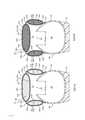
特別參考圖1A至圖3B,一調整元件200、200a經提供且經構形以附接至一鞋類物件100 (圖4A至圖4C)之一鞋面110,以調整環繞腳之鞋類物件100的一調整區106之一尺寸。調整元件200、200a包含形成一內部空隙204之一囊袋202,內部空隙204具有安置於其中之一可壓縮組件206、206a。囊袋202進一步包含提供囊袋202之內部空隙204與一外部之間的流體連通之至少一閥208a、208b。1A-3B, an
如圖2A及圖3A中最佳展示,囊袋202包含一對障壁層210,障壁層210各具有一外表面212及形成於障壁層210之與外表面212相對之一側上之一內表面214。障壁層210之內表面214彼此相對或面向彼此,且沿著一接縫216彼此接合以將囊袋202分離成複數個腔室218a至218c。As best shown in FIGS. 2A and 3A , the
如本文中所使用,術語「障壁層」(例如,障壁層210)涵蓋單層膜及多層膜兩者。在一些實施例中,障壁層210之一或兩者各由一單層膜(一單個層)產生(例如,熱成型或吹氣模製)。在其他實施例中,障壁層210之一或兩者各由一多層膜(多個子層)產生(例如,熱成型或吹氣模製)。As used herein, the term "barrier layer" (eg, barrier layer 210) encompasses both monolayer films and multilayer films. In some embodiments, one or both of the barrier layers 210 are each produced from a single layer film (a single layer) (eg, thermoformed or blow molded). In other embodiments, one or both of the barrier layers 210 are each produced from a multilayer film (sublayers) (eg, thermoformed or blow molded).
障壁層210可各由包含一或多個熱塑性聚合物及/或一或多個可交聯聚合物之一彈性材料產生。在一態樣中,該彈性材料可包含一或多個熱塑性彈性材料,諸如一或多個熱塑性聚胺基甲酸酯(TPU)共聚物、一或多個乙烯-乙烯醇(EVOH)共聚物及類似者。The barrier layers 210 may each be produced from an elastic material comprising one or more thermoplastic polymers and/or one or more crosslinkable polymers. In one aspect, the elastomeric material may comprise one or more thermoplastic elastomeric materials, such as one or more thermoplastic polyurethane (TPU) copolymers, one or more ethylene-vinyl alcohol (EVOH) copolymers and the like.
如本文中所使用,「聚胺基甲酸酯」係指含有一胺基甲酸酯基團(-N(C=O)O-)之一共聚物(包含低聚物)。除了胺基甲酸酯基團之外,此等聚胺基甲酸酯基亦可含有額外基團,諸如酯、醚、脲、脲基甲酸酯、縮二脲、碳化二亞胺、噁唑烷基、異氰尿酸酯、異氰酸酯二聚體、碳酸酯及類似者。在一態樣中,可由使一或多個異氰酸酯與一或多個多元醇聚合以產生具有(-N(C=O)O-)鍵聯之共聚物鏈來產生聚胺基甲酸酯之一或多者。As used herein, "polyurethane" refers to a copolymer (including oligomers) containing a monourethane group (-N(C=O)O-). In addition to the urethane groups, these polyurethane groups may also contain additional groups such as esters, ethers, ureas, allophanates, biurets, carbodiimides, oxanes oxazolidines, isocyanurates, isocyanate dimers, carbonates and the like. In one aspect, polyurethanes can be produced by polymerizing one or more isocyanates with one or more polyols to produce copolymer chains with (-N(C=O)O-) linkages. one or more.
用於產生聚胺基甲酸酯共聚物鏈之合適異氰酸酯之實例包含二異氰酸酯,諸如芳族二異氰酸酯、脂族二異氰酸酯及其等之組合物。合適芳族二異氰酸酯之實例包含甲苯二異氰酸酯(TDI)、TDI與三甲醯基丙烷之加成物(TMP)、亞甲基二苯基二異氰酸酯(MDI)、二甲苯二異氰酸酯(XDI)、四甲基二甲苯二異氰酸酯(TMXDI)、氫化二甲苯二異氰酸酯(HXDI)、萘1,5-二異氰酸酯(NDI)、1,5-四氫萘二異氰酸酯、對亞苯基二異氰酸酯(PPDI)、3,3' –二甲基二苯基1-4、4' –二異氰酸酯(DDDI)、4,4 '-二苄基二異氰酸酯(DBDI)、4-氯-1,3-亞苯基二異氰酸酯及其等之組合物。在一些實施例中,共聚物鏈基本上無芳族基團。Examples of suitable isocyanates for producing polyurethane copolymer chains include diisocyanates, such as combinations of aromatic diisocyanates, aliphatic diisocyanates, and the like. Examples of suitable aromatic diisocyanates include toluene diisocyanate (TDI), adducts of TDI with trimethylpropane (TMP), methylene diphenyl diisocyanate (MDI), xylene diisocyanate (XDI), tetra Methyl xylene diisocyanate (TMXDI), hydrogenated xylene diisocyanate (HXDI),
在特定態樣中,聚胺基甲酸酯聚合物鏈係由包含HMDI、TDI、MDI、H12脂族化合物及其等之組合物之二異氰酸酯產生。在一態樣中,熱塑性TPU可包含聚酯基TPU、聚醚基TPU、聚己內酯基TPU、聚碳酸酯基TPU、聚矽氧烷基TPU或其等之組合物。In particular aspects, the polyurethane polymer chains are produced from diisocyanates comprising compositions of HMDI, TDI, MDI, H12 aliphatic compounds, and the like. In one aspect, the thermoplastic TPU may comprise polyester-based TPU, polyether-based TPU, polycaprolactone-based TPU, polycarbonate-based TPU, polysiloxane-based TPU, or combinations thereof.
在另一態樣中,聚合物層可由以下一或多者形成:EVOH共聚物、聚(氯乙烯)、聚乙二烯聚合物及共聚物(例如,聚偏二氯乙烯)、聚醯胺(例如,非晶聚醯胺)、醯胺基共聚物、丙烯腈聚合物(例如,丙烯腈-丙烯酸甲酯共聚物)、聚對苯二甲酸乙二酯、聚醚醯亞胺、聚丙烯酸酯及已知具有相對較低氣體傳輸速率之其他聚合物材料。此等材料以及與本文中所描述之TPU共聚物且視需要包含聚醯亞胺及結晶聚合物之組合之混合物亦係合適的。In another aspect, the polymer layer can be formed from one or more of the following: EVOH copolymers, poly(vinyl chloride), polyethylene diene polymers and copolymers (eg, polyvinylidene chloride), polyamide (eg, amorphous polyamide), amide-based copolymers, acrylonitrile polymers (eg, acrylonitrile-methyl acrylate copolymer), polyethylene terephthalate, polyetherimide, polyacrylic acid Esters and other polymeric materials known to have relatively low gas transmission rates. Also suitable are mixtures of these materials, as well as mixtures with the TPU copolymers described herein, and optionally including combinations of polyimides and crystalline polymers.
囊袋202可使用任何合適技術由障壁層210產生,諸如熱成型(例如,真空熱成型)、吹氣模製、擠壓、注射模製、真空模製、旋轉模製、轉移模製、壓力成型、熱封、澆鑄、低壓澆鑄、旋塗澆鑄、反應注射模製、射頻(RF)焊接及類似者。The
在所繪示實例中,囊袋202包含一中心腔室218a及附接至中心腔室218a之彼此相對之側之一對翼腔室218b、218c。參考圖1A及圖1B,腔室218a至218c之各者沿著一縱軸A218a-A218c自一第一端220a至220c延伸至安置於腔室218a至218c之與第一端220a至220c相對之一端上之一第二端222a至222c。腔室218a至218c之各者進一步包含自各自第一端220a至220c延伸至各自第二端222a至222c之一對側224a至224c、226a至226c。In the illustrated example, the
通常,第一翼腔室218b之第一側224b經構形以在調整區106之一第一側上附接至鞋面110,且第二翼腔室218c之一第一側224c經構形以在調整區106之與第一翼腔室218b相對之側上附接至鞋面110 (圖4A至圖4C)。中心腔室218a在第一翼腔室218b之第二側226b與第二翼腔室218c之第二側226c之間延伸且連接第一翼腔室218b之第二側226b與第二翼腔室218c之第二側226c,且經構形以在翼腔室218b、218c附接至鞋面110時跨越調整區106之間隙。因此,如下文參考圖4A至圖5B更詳細論述,當調整元件200、200a在膨脹構形(圖4A)與收縮構形(圖4C)之間移動時,翼腔室218b、218c可操作以使調整區106在一第一寬度W106-1與一第二寬度W106-2之間移動。Typically, the
如圖1A中所展示,腔室218a至218c之各者之一寬度(即,側之間的距離)自第一端220a至220c至第二端222a至222c逐漸減小,使得調整元件200、200a之一總寬度亦逐漸減小。在所繪示實例中,中心腔室218a經形成具有一梯形形狀,藉此第一側224a與第二側226a在第一端220a處及在第二端222a處彼此間隔開,且沿著自第一端220a至第二端222a之一方向彼此會聚。翼腔室218b、218c經形成為三角形結構,其中第一側224b、224c係與第二側226b、226c在第一端220b、220c處間隔開且在第二端222b、222c處彼此交叉。在其他實例中,腔室218a至218c之一或多者可經形成具有平行或發散側224a至224c、226a至226c。As shown in FIG. 1A , a width (ie, the distance between the sides) of each of the
參考圖2A,囊袋202可包含將腔室218a至218c之相鄰者流體地耦合在一起之一或多個導管228。在所繪示實例中,導管228係跨囊袋202之接縫216之一寬度、在障壁層210之內表面214之間形成。此處,障壁層210係沿著接縫216之一或多個部分彼此分離使得流體可穿過接縫216及在障壁層210之間自一個腔室218a至218c穿過至另一腔室218a至218c。Referring to Figure 2A, the
視需要,接縫216可包含各自一個障壁層210之外表面212延伸通過接縫216之一厚度至另一障壁層210之外表面212之穿孔230。因此,穿孔230容許空氣在其中障壁層210彼此接合之腔室218a至218c之間通過接縫216之部分。因此,穿孔230對安置於接縫216下面之鞋面110之部分提供通風及透氣性。If desired, the
如圖2A中最佳展示,囊袋202進一步包含安置於內部空隙204內之一對承載層232。各承載層232具有一外表面234及形成於承載層232之與外表面234相對之一側上之一內表面236。在所繪示實例中,承載層232之外表面234直接附接至障壁層210之內表面214,使得承載層232之內表面236面向彼此。可藉由將各承載層232之外表面234接合至障壁層210之內表面214之一各自者而將承載層232附接至障壁層210之內表面214。替代性地,承載層232可藉由中間材料層間接地附接至障壁層210之內表面214。As best shown in FIG. 2A , the
通常,承載層232經構形以提供可壓縮組件206、206a與障壁層210之間的一低摩擦介面。因此,承載層232或至少承載層232之內表面236包含具有低於形成障壁層210之內表面214之材料的一摩擦係數之一材料。在一些實例中,承載層232之材料係一織物材料。例如,該織物材料可為一四向拉伸織物(即,橫向及縱向拉伸之一材料)。合適材料之實例包含編織織物、歐洲織造織物及可拉伸合成織物。雖然所繪示之承載層232經展示為包含一單個材料層,但承載層232可視需要形成為一層壓體,藉此外表面234係由提供所要結構性質(諸如剛性或黏合力)之一第一材料形成,且內表面236係由提供所要摩擦性質之一第二材料形成。Typically, the
如圖2A及圖2B中最佳展示,承載層232之各者可分離成對應於囊袋202之腔室218a至218c之各者之複數個片段238a至238c。因此,雖然障壁層210各經連續地形成,但承載層232係斷開的,使得片段238a至238c之各者覆蓋與各腔室218a至218c相關聯之障壁層210之內表面214之一部分。片段238a至238c係藉由囊袋202之接縫216分離及定界。As best shown in FIGS. 2A and 2B , each of the carrier layers 232 may be separated into a plurality of segments 238a - 238c corresponding to each of the
繼續參考圖2A至圖3B,可壓縮組件206、206a安置於承載層232之內表面236之間,使得形成於承載層232之內表面236之間的內部空隙204之部分係用可壓縮組件206、206a填充。通常,可壓縮組件206、206a包含經構形以使腔室218a至218c之各者偏置朝向一膨脹狀態之一或多個回彈性材料或結構。特定言之,可壓縮組件206、206a可包含與承載層232之內表面236面對接觸之外表面240,藉此可壓縮組件206、206a之一回彈性引起可壓縮組件206、206a之外表面240抵靠承載層232之內表面236施加一力以使腔室218a至218c偏置朝向膨脹狀態。如同承載層232,可壓縮組件206、206a可藉由囊袋202之接縫216分離成複數個離散部分。因此,可壓縮組件206、206a之各部分安置於腔室218a至218c之一對應者內,且經構形以使個別腔室218a至218c偏置朝向膨脹狀態。With continued reference to FIGS. 2A-3B ,
在一些實例中,可壓縮組件206、206a之部分可包含安置於腔室218a至218c之各者內之單式可壓縮元件242a至242c,如圖2A中所展示。可壓縮元件242a至242c各由一回彈性材料或結構(諸如一開孔發泡體材料)形成,該回彈性材料或結構容許一流體自由地通過其。圖5B及圖6B之調整元件200a係以實質上類似於上文所描述及在圖5A及圖6A中所展示之調整元件200之一方式構造。然而,可壓縮組件206a可包含複數個個別可壓縮粒子244,而非由一單式材料形成,藉此各腔室218a至218c係填充有可壓縮粒子244且可壓縮粒子244能夠在各腔室218a至218c內相對於彼此移動。可壓縮粒子可由一發泡體材料形成,諸如一熱塑性聚胺基甲酸酯(TPU)或其他類型之發泡體。在一些實例中,可壓縮粒子244經形成為球形珠,且協作以共同界定可壓縮組件206之外表面240。In some examples, portions of the
再次參考圖1A,囊袋202可裝配有可操作以提供囊袋202之內部空隙204與一外部之間的流體連通之一或多個閥208a、208b。在所繪示實例中,囊袋202包含安置於中心腔室218a之第二端222a處之一排出閥208a及安置於中心腔室218a之第一端220a處之一進入閥208b。然而,閥208a、208b之任一者可提供於腔室218a至218c之任一者上,此係因為腔室218a至218c係透過導管228彼此流體連通。在一些實例中,排出閥208a及進入閥208b可體現為經構形以作為一進入閥及一排出閥用於雙向操作之一單個閥。Referring again to Figure 1A, the
排出閥208a經構形以選擇性地打開以容許流體在自囊袋202之內部空隙204至一外部之一方向上通過。在一些實例中,排出閥208a經構形為一被動閥,藉此藉由跨排出閥208a施加一流體壓力差而將排出閥208a移動至打開位置。例如,排出閥208a可經構形以在閥208a之一入口側與一出口側之間的一壓力差滿足或超過一壓力臨限值時打開。被動閥之實例可包含止回閥,諸如鴨嘴閥、擺動式閥、旋塞型閥、球型閥及類似者。
在一些實例中,可藉由在排出閥208a之一入口側上施加一正壓力而產生一壓力差。可藉由壓縮腔室218a至218c之一或多者,從而迫使流體自內部空隙204通過排出閥208a,而在排出閥208a之該入口側上產生一正壓力。視需要,可藉由在閥208a之一出口側上施加一負壓力來產生壓力差。例如,排出閥208a之該出口側可連接至一真空源(諸如一泵246)。此處,泵246經構形以在排出閥208a之出口側上抽吸一負壓力以將流體自內部空隙204拉過排出閥208a。雖然所繪示之泵246經展示為安置於鞋面110上,但在其他實例中囊袋202可連接至未直接併入至服飾物件中之一周邊泵(諸如一手動泵或一電動泵)。In some examples, a pressure differential can be created by applying a positive pressure on an inlet side of the
在所繪示實例中,進入閥208b安置於中心腔室218a之第一端220a處且可在容許流體流動至囊袋202之內部空隙204中之一打開位置與防止流體流動至內部空隙204中之一關閉位置之間操作。進入閥208b可由使用者在該打開位置與該關閉位置之間選擇性地移動。在一實例中,進入閥208b經體現為可被開封及重新密封以打開及關閉進入閥208b之一拉鏈。In the illustrated example, the
除了上文所論述之被動閥208a、208b之外,閥208a、208b之任一者或兩者可體現為經構形以被手動地打開及關閉之一主動閥。例如,閥208a、208b可為可由穿著者在打開位置與關閉位置之間移動之一手動閥。在其他實例中,排出閥208a、208b可體現為上文所論述之止回閥之任一者,且可包含連接至用於將閥208a、208b偏置至一打開位置之閥機構之一釋放手柄。在一些實例中,形狀金屬合金可併入至排出閥中,藉此合金之一形狀隨一溫度變化而改變以使閥208a、208b在打開位置與關閉位置之間移動。In addition to the
在圖4A至圖6B之實例中,提供呈具有一鞋面110及附接至鞋面110之底部之一鞋底結構112的一鞋類物件100之形式的容槽100。因此,內部空隙102經構形以收納一穿著者之一腳且開口104係提供出入鞋類100之一腳跟區之出入口之一腳踝開口。通常,鞋底結構112經構形以對鞋類物件100提供緩衝及回應性之特性,而鞋面110經構形以收納穿著者之腳以將穿著者之腳固定至鞋底結構112。In the example of FIGS. 4A-6B ,
當體現為一鞋類物件100時,容槽之調整區106經形成為沿著鞋面110之一背側區延伸之一腳背以調整環繞腳之內部空隙102之貼合,並適應腳伸入內部空隙102及自內部空隙102抽出。如所展示,調整區106自腳踝開口104處之一第一端114延伸至一前足區中之與腳踝開口104間隔開之一第二端116。然而,調整區106可形成於鞋面110之其他區域中,諸如沿著鞋面110之一外側或一內側。如圖5A及圖6A中所展示,調整區106經形成為穿過鞋面110之一間隙或空間,其中可增加或減小該間隙之一寬度W106以調整鞋面110之一貼合。此外或替代性地,調整區106可包含經構形以在一拉伸狀態與一收縮狀態之間移動以調整鞋面110之一尺寸之一或多個彈性材料。When embodied as an article of
在所繪示實例中,當調整元件200、200a附接至鞋面110時,腔室218a至218c之第一端220a至220c鄰近於腳踝開口104定位,而第二端222a至222c定位於中足區中,在調整區106上方。第一翼腔室218b之第一側224b在調整區106之一第一側上附接至鞋面110且第二翼腔室218c之一第一側224c在調整區106之與第一翼腔室218b相對之側上附接至鞋面110。In the depicted example, when
現參考圖4A至圖4C,展示及描述調整元件200、200a自膨脹構形(圖4A)至收縮構形(圖4C)之移動。在膨脹構形中,囊袋202之內部空隙204係填充有流體使得內部空隙204係處於等於或大於大氣壓之一壓力下。因而,可壓縮組件206、206a能夠使承載層232及障壁層210向外偏置以使腔室218a至218c之各者移動至一膨脹狀態,如圖5A中所展示。當腔室218a至218c之各者處於膨脹狀態時,翼腔室218b、218c延伸,使得第一側224b、224c附接至鞋面110且第二側226b、226c跨翼腔室218b、218c與第一側224b、224c間隔開。如所展示,中心腔室218a係藉由翼腔室218b、218c與鞋面110間隔開且調整區106具有一膨脹之第一寬度W106-1。在膨脹構形中,腔室218a至218c通常自第一翼腔室218b之第一端224b至第二翼腔室218c之第一端224c彼此串聯配置。Referring now to FIGS. 4A-4C, the movement of the
參考圖4B,藉由透過排出閥208a將流體自內部空隙204排出而將調整元件200、200a自膨脹構形(圖4A)轉變至收縮構形(圖4C)。如上文所論述,可藉由在排出閥208a之入口側上施加一正壓力(例如,藉由擠壓或壓縮囊袋202)及/或藉由在排出閥208a之出口側上施加一負壓力(例如,藉由使用一真空泵)而將流體自內部空隙204排出。在流體自內部空隙204排出時,藉由障壁層210在內部空隙204內壓縮可壓縮組件206、206a。藉由一穿著者直接地(即,用該穿著者之手)或藉由收緊至少部分在調整元件200、200a上方延伸之鞋帶(未展示)而間接地壓下調整元件200、200a,可將施加於調整元件200、200a上之壓力直接施加至調整元件200、200a之一外表面。Referring to FIG. 4B, the
現參考圖4C,調整元件200、200a移動至完全壓縮構形。此處,腔室218a至218c之各者處於一完全壓縮狀態,使得形成可壓縮組件206、206a之材料之孔(pore/cell)實質上完全塌縮(collapse)。當腔室218a至218c處於完全壓縮狀態時,可壓縮組件206、206a之回彈性引起可壓縮組件206、206a之外表面240抵靠承載層232之內表面236且因此對障壁層210施加一向外偏置力。然而,由於排出閥208a經構形以防止流體流動至內部空隙204中,因此防止腔室218a至218c返回至其等各自膨脹狀態。代替性地,可壓縮組件206、206a抵靠囊袋202之障壁層210之偏置力引起在內部空隙204內形成一真空(即,負壓力)以使腔室218a至218c維持於壓縮狀態。Referring now to Figure 4C, the
當腔室218a至218c處於壓縮狀態時,腔室218a至218c可自身折疊起來以減小調整元件200、200a之一有效寬度。例如,如圖4C及圖6A中所繪示,翼腔室218b、218c可沿著其等各自縱軸A218b、A218c折疊。因此,各翼腔室218b、218c之第二側226b、226c折疊在各自翼腔室218b、218c之第一側224b、224c上方。因此,將中心腔室218a之第一側224a及第一翼腔室218b之第一側224b朝向彼此牽拉,而將中心腔室218a之第二側226a及第二翼腔室218c之第一側224c朝向彼此牽拉。如圖4C及圖6A中所展示,當翼腔室218b、218c沿著其等縱軸A218b、A218c折疊時,翼腔室218b、218c將在中心腔室218a下面折疊。此外,調整元件200、200a之有效寬度之縮減引起調整區106收縮至小於第一寬度W106-1之第二寬度W106-2,從而使鞋面110環繞穿著者之腳收緊。When the
為使調整元件200、200a返回至膨脹構形,將進入閥208b移動至一打開位置以容許流體流動至囊袋202之內部空隙204中。特定言之,在進入閥208b處於該打開位置中之情況下,可壓縮組件206、206a之回彈性使障壁層210向外偏置以增加內部空隙之體積,從而透過進入閥208b抽吸流體直至可壓縮組件206、206a達到一完全膨脹狀態。在一些實例中,可計量通過進入閥208b之流體流以便僅容許可壓縮組件206、206a移動至一部分膨脹狀態。在需要鞋面110在腳上較鬆散貼合之情況下,使用該部分膨脹狀態。To return the
特別參考圖7A至圖10B,展示調整元件200b、200c之構形之額外實例。鑑於與調整元件200相關聯之組件相對於調整元件200b、200c之結構及功能實質相似性,在下文及圖式中使用相同元件符號來識別相同組件,而使用含有字母擴展之相同元件符號來識別經修改之彼等組件。With particular reference to Figures 7A-10B, additional examples of the configuration of
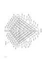
如同上文所描述之調整元件200,圖7A至圖9B之調整元件200b、200c包含一囊袋202a,囊袋202a具有在離散位置處接合在一起以界定一接縫216a及複數個腔室218d至218j之一對障壁層210。囊袋202a沿著一縱軸A202a延伸且實質上圍繞縱軸A202a對稱且包含配置於縱軸A202a之一第一(例如,外)側上之第一系列腔室218d至218j及配置於縱軸A202a之一第二(例如,內)側上之第二系列腔室218d至218j。腔室218d至218j通常為長形且自一第一端220d至220j縱向延伸至一第二222d至222j。As with the
如所展示,各系列中之腔室218d至218j係相對於縱軸A202a以一傾斜角定向。特定言之,腔室218d至218j之各者之一長度沿著自與縱軸A202a間隔開之第一端220d至220j至鄰近於縱軸A202a之第二端222d至222j之一方向延伸。換言之,腔室218d至218j之各者沿著縱軸A202a之一方向延伸且沿著自第二端222d至222j至第一端220d至220j之一方向偏離縱軸A202a。各系列中之腔室218d至218j可彼此平行配置。因此,縱軸A202a之第一側上之第一系列腔室218d至218j全部偏離在縱軸A202a之第二側上之第二系列之腔室218d至218j。在其他實例中,腔室218d至218j可為非平行的,或可配置為一腔室陣列。As shown, the
繼續參考圖8A及圖9A,腔室218d至218j之各者進一步包含一第一側224d至224j及形成於腔室218d至218j之與第一側224d至224j相對之一側上之一第二側226d至226j。此處,第一側224d至224j及第二側226d至226j之各者沿著各自腔室218d至218j之長度自第一端220d至220j延伸至第二端222d至222j。對於各系列腔室218d至218j,第一側224d至224j向內面向縱軸A202a,而第二側226d向外背對縱軸A202a。各腔室218d至218j之第一側226d至226j沿著囊袋202a之接縫216a附接至腔室218d至218j之一相鄰者之第二側226d至226j。8A and 9A, each of the
如同上文所論述之囊袋202,圖7A及圖7B之囊袋202a包含將腔室218d至218j之各者流體地耦合在一起之一或多個導管228a。如圖8A及圖9A中最佳繪示,囊袋202a之導管228a可經構形為沿著縱軸A202a連續延伸且連接腔室218d至218j之各者之第二端222d至222j之一中心歧管。因此,腔室218d至218j之各者係透過導管228a彼此連通,如圖7A及圖7B中所展示。Like the
囊袋202a可包含與囊袋202a之內部空隙204a連通且經構形以選擇性地容許流體流動至囊袋202a中及/或流出囊袋202a之一或多個閥208c、208d。在所繪示實例中,囊袋202a包含安置於囊袋202a之相對側上之一對排出閥208c。例如,一第一排出閥208c安置於囊袋202a之第一側上且與第一側上之腔室218j之一最外者直接流體連通,而一第二排出閥208c安置於囊袋202a之第二側上且與第二側上之腔室218j之一最外者直接流體連通。The
囊袋202a進一步包含安置於一端處之一進入閥208d。如所展示,進入閥208d係沿著縱軸A202a安置且與導管228a直接流體連通。雖然進入閥208d經展示為鄰近於腔室218d至218j之第一端220d至220j定位,但進入閥208d可鄰近於腔室218d至218j之第二端222d至222j定位。此外或替代性地,一或多個進入閥208d可以類似於排出閥208c之一方式直接流體耦合至腔室218d至218j之一者。The
參考圖8A至圖9B,圖7A及圖7B之調整元件200b、200c係以類似於上文所描述之調整元件200、200a之一方式構造。特定言之,調整元件包含沿著接縫216a彼此接合以界定內部空隙204a之一輪廓及形成複數個腔室218d至218j之障壁層210。囊袋202a進一步包含附接至障壁層210之相對內表面214之一或多個承載層232,其中承載層232被再劃分成對應於形成各腔室218d至218j之內表面214之部分之複數個片段238d至238j。一可壓縮組件206b、206c安置於內部空隙204a內。8A-9B, the
參考圖8A及圖9A,在一實例中,調整元件200b可用包含填充藉由腔室218d至218j之各者界定之內部空隙204b之一部分之複數個單式可壓縮元件242d至242j之一可壓縮組件206b形成。在調整元件206c之另一實例中,腔室218d至218j之各者可用上文所論述之可壓縮粒子244填充。Referring to Figures 8A and 9A, in one example,
在使用中,圖7A至圖9B之調整元件200b、200c藉由改變囊袋202a之內部空隙204a內之一流體壓力而在一收縮構形(圖7A)與一膨脹構形(圖7B)之間移動。然而,不同於上文所論述之囊袋202,圖7A至圖9B之囊袋202a在內部空隙204a內之流體壓力等於或大於大氣壓時移動至該收縮構形,且在內部空隙204a內之流體壓力小於大氣壓時移動至該膨脹構形。In use, the
特別參考圖7A、圖8A及圖8B,調整元件200b、200c經展示在收縮構形中。此處,囊袋202a之內部空隙204a內之流體壓力等於或大於大氣壓使得可壓縮組件206b、206c能夠使囊袋202a之障壁層210分開偏置以使腔室218d至218j移動至一膨脹狀態。在該膨脹狀態中,最大化腔室218d至218j之厚度(即,障壁層210之外表面212之間的距離),而最小化寬度(即,第一側224d至224j與第二側226d至226j之間的距離)。因此,在障壁層210偏置而彼此分開時,將腔室218d至218j之相鄰者朝向彼此牽拉,從而引起最小化囊袋202a之一總寬度(即,跨所有腔室218d至218j之距離)。With particular reference to Figures 7A, 8A and 8B,
參考圖7B、圖9A及圖9B,為使調整元件200b、200c移動至膨脹構形,將內部空隙204a內之一流體壓力降低至低於大氣壓使得將障壁層210朝向彼此牽拉以最小化腔室218d至218j之厚度。如上文所論述,藉由自內部空隙204a移除一體積之流體來降低流體壓力。此可藉由直接地或間接地(即,經由鞋帶)壓縮(例如,擠壓)腔室來完成,以在排出閥208c之一入口側上產生一正壓力,從而引起迫使流體通過排出閥208c且從囊袋202a流出。此外或替代性地,可藉由對真空閥208c之一出口側施加一真空來移除流體。Referring to Figures 7B, 9A and 9B, to move the
一旦流體離開內部空隙204a,可壓縮組件206b、206c之回彈性便施加一偏置力至囊袋之承載層232以使障壁層210偏置而彼此分開。然而,在移除壓力差之情況下,排出閥208c移動至一關閉位置以防止流體流動至內部空隙中。因此,可壓縮組件206b、206c之偏置力在內部空隙204a內產生一負壓力,該負壓力使腔室218d至218j維持於壓縮狀態。Once the fluid leaves the
如圖9A及圖9B中所展示,當腔室218d至218j係在壓縮狀態時,最小化腔室218d至218j之一厚度且最大化腔室218d至218j之寬度。此外,將腔室218d至218j移動至壓縮狀態容許囊袋202a之接縫216a在腔室218d至218h之相鄰者之間移動至一鬆弛狀態,此係因為自接縫216a之經接合障壁層210至各腔室218d至218j之分離障壁層210之轉變更平緩。在腔室218d至218j處於壓縮狀態之情況下,最大化囊袋202a之一總寬度。As shown in Figures 9A and 9B, when the
參考圖10A及圖10B,在一實例中,調整元件200b、200c併入於一鞋類物件100上。類似於上文所論述之物件10、10a,此處物件10b、10c包含具有安置於鄰近於一腳踝開口104之一腳背區中之調整區106之鞋類物件100。為調整鞋類物件100之一貼合,藉由改變囊袋202a之內部空隙204a內之流體壓力來使調整元件200b、200c在收縮構形(圖10A)與膨脹構形(圖10B)之間移動。Referring to FIGS. 10A and 10B , in one example,
如圖11A及圖11B中所展示,在一物件10d、10e之另一實例中,調整元件200b、200c併入於一衣服(諸如一襯衫100a)上。此處,襯衫100a包含形成一主體腔之一內部空隙102a,其中襯衫100a中之一開口104a提供內部空隙102a之出入口。如所展示,襯衫100a可包含一調整區106a。如同鞋類物件100,襯衫100a之調整區106a可由一彈性材料形成,或在襯衫100a之該材料中可包含一間隙。As shown in Figures 11A and 11B, in another example of an
當調整元件200b、200c併入於一襯衫100a或其他衣服中時,調整元件200b、200c將安置於調整區106a上方。在一些實例中,調整區106a可鄰近於開口104a形成以調整開口104a環繞身體之貼合。例如,在開口104a提供為如所展示之一領口104a之情況下,調整元件200b、200c可經構形以調整領口104a環繞一穿著者之頸部之貼合。在其他實例中,調整區106a及調整元件200b、200c係與開口104a間隔開以調整襯衫100a之一中間部分之貼合。When the
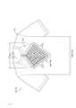
現參考圖12A及圖12B,展示一調整元件200d之另一實例。此處,調整元件200d係用類似於調整元件200至200c之一構造形成,且包含一囊袋202b,囊袋202b具有沿著一接縫216b彼此接合以形成複數個腔室218k之一對障壁層210。通常,調整元件200d具有一拉脹結構,其中在調整元件200d移動至收縮構形(圖12A)時最小化調整元件200d之一長度L200d及一寬度W200d,且在調整元件200d移動至膨脹構形(圖12B)時最大化調整元件200d之長度L200d及寬度W200d。Referring now to Figures 12A and 12B, another example of an
參考圖12A及圖12B,囊袋202b之接縫216b形成界定複數個離散多邊形腔室218k之一互連網狀物或網格。在所繪示實例中,接縫216b界定以列及行配置之複數個菱形或正方形腔室218k以對囊袋202b提供拉脹結構。接縫216b可包含將腔室218k之各者部分劃分成一對相對三角形腔室區段250之複數個指狀物248。腔室218k之各者可用形成於接縫216b中之一或多個導管228b彼此流體耦合。Referring to Figures 12A and 12B,
調整元件200d可進一步包含如上文所論述之一或多個閥。在所繪示實例中,一單個雙向閥208e係透過導管228b之網狀物流體地連接至腔室218k之各者。因此,閥208e即可用作用於自囊袋202b移除流體之一排出閥且又用作用於提供流體至囊袋202b之一進入閥。
調整元件200b包含安置於腔室218k之各者內且經構形以使調整元件200b之障壁層210偏置而彼此分開的一可壓縮組件。如同上文所提供之實例,該可壓縮組件可包含各填充腔室218k之一者且由一回彈性材料218k (諸如開孔發泡體)形成之複數個單式可壓縮元件。此外或替代性地,調整元件200b之可壓縮組件可包含安置於各腔室218k內之複數個可壓縮粒子244。The
在使用中,藉由改變囊袋202b內之一流體壓力使調整元件200d在收縮構形(圖12A)與膨脹構形(圖12B)之間移動。在圖12A中,當囊袋202b內之一流體壓力等於或大於大氣壓時,調整元件200d經配置處於收縮構形,使得各腔室218k內之可壓縮組件可使障壁層210偏置而彼此分開。此處,在障壁層210偏置而彼此分開時,最小化各腔室218k之一長度L218k及一寬度W218k且將腔室218k及接縫216b朝向彼此牽拉。因此,最小化調整元件200b之一總長度L200d-1及總寬度W200d-1。In use,
為使調整元件200d移動至膨脹構形,透過閥208e自囊袋202b內排出一體積之流體。如同先前實例,可藉由跨閥208e產生一壓力差使得囊袋202b內之流體壓力大於閥208e外部上之流體壓力來排出流體。在自囊袋202b排出流體時,將障壁層210朝向彼此牽拉以在囊袋202b之內部空隙內壓縮可壓縮組件,從而減小腔室218k之各者之一厚度。腔室218k之厚度之縮減導致各腔室218k之寬度W218k及長度L218k增加,此因此導致最大化囊袋202b之總長度L200d-2及總寬度W200d-2。To move
在調整元件200d在膨脹構形中之情況下,接著關閉閥208e以防止流體流動至囊袋中。如上文所論述,可壓縮組件施加一偏置力至障壁層210以使障壁層210彼此分開移動。然而,在閥208e在關閉位置中之情況下,流體無法流動至囊袋202b中且在內部空隙內形成一真空,從而使調整元件200d維持於膨脹構形中直至打開閥208e以容許流體返回至內部空隙。With
參考圖13A及圖13B,調整元件200d併入至上文所描述之鞋類物件100上。圖14A及圖14B展示併入至一衣服(諸如一襯衫100a)上之調整元件200d。在兩個實例中,在調整元件200d在膨脹狀態與收縮狀態之間移動時,調整元件200b之拉脹結構容許可調整區106、106a之一高度及寬度膨脹及收縮。因此,不同於提供雙向貼合調整之先前實例,拉脹結構提供四向貼合調整。Referring to Figures 13A and 13B,
以下條項提供上文所描述之一鞋類物件之一例示性構形。The following clause provides an exemplary configuration of an article of footwear described above.
條項1:一種物件,其包括:一容槽,其界定一內部空隙;及一調整元件,其附接至該容槽且包含界定一或多個腔室之一囊袋,各腔室具有安置於其中之一可壓縮組件,該調整元件藉由調整該一或多個腔室內之一壓力而可在對該容槽提供一第一尺寸之一收縮構形與對該容槽提供一第二尺寸之一膨脹構形之間操作,該第二尺寸不同於該第一尺寸。Clause 1: An article comprising: a cuvette defining an interior void; and an adjustment element attached to the cuvette and including a pocket defining one or more chambers, each chamber having Disposed in one of the compressible components, the adjustment element can provide the cavity with a collapsed configuration of a first dimension and a first dimension of the cavity by adjusting a pressure in the one or more chambers Operates between expanded configurations of one of two dimensions, the second dimension being different from the first dimension.
條項2:如條項1之物件,其中該容槽包含提供該內部空隙之出入口之一開口,該調整元件鄰近於該開口安置且可操作以使該開口在該第一尺寸與該第二尺寸之間移動。Clause 2: The article of
條項3:如條項1或2之物件,其中該囊袋包含在離散位置處接合在一起以界定該一或多個腔室之一第一障壁層及一第二障壁層。Clause 3: The article of
條項4:如條項3之物件,其中該囊袋包含鄰近於該第一障壁層之一第一承載層及鄰近於該第二障壁層之一第二承載層。Clause 4: The article of clause 3, wherein the pocket comprises a first carrier layer adjacent to the first barrier layer and a second carrier layer adjacent to the second barrier layer.
條項5:如條項4之物件,其中該可壓縮組件安置於該第一承載層與該第二承載層之間。Clause 5: The article of clause 4, wherein the compressible element is disposed between the first carrier layer and the second carrier layer.
條項6:如條項4或5中任一項之物件,其中該第一承載層及該第二承載層具有低於該第一障壁層及該第二障壁層之一摩擦係數。Clause 6: The article of any one of clauses 4 or 5, wherein the first carrier layer and the second carrier layer have a lower coefficient of friction than the first barrier layer and the second barrier layer.
條項7:如條項4至6中任一項之物件,其中該承載層係由一織物材料形成。Clause 7: The article of any one of clauses 4 to 6, wherein the carrier layer is formed of a textile material.
條項8:如前述條項中任一項之物件,其中該可壓縮組件包含一單式元件。Clause 8: The article of any preceding clause, wherein the compressible member comprises a single element.
條項9:如條項1至7中任一項之物件,其中該可壓縮組件包含複數個可壓縮粒子。Clause 9: The article of any one of
條項10:如條項9之物件,其中該複數個可壓縮粒子係球形珠。Clause 10: The article of
條項11:如前述條項中任一項之物件,其中該可壓縮組件係由一發泡體材料形成。Clause 11: The article of any of the preceding clauses, wherein the compressible member is formed of a foam material.
條項12:如前述條項中任一項之物件,其中該調整元件包含提供該一或多個腔室之各者與該囊袋之一外部之間的流體連通之一閥。Clause 12: The article of any preceding clause, wherein the adjustment element comprises a valve providing fluid communication between each of the one or more chambers and an exterior of the bladder.
條項13:如前述條項中任一項之物件,其中該一或多個腔室包含複數個腔室。Clause 13: The article of any preceding clause, wherein the one or more chambers comprise a plurality of chambers.
條項14:如條項13之物件,其中該複數個腔室係彼此流體連通。Clause 14: The article of
條項15:如條項1之物件,其中該容槽係一鞋類物件之一鞋面。Clause 15: The article of
條項16:如條項15之物件,其中該調整元件安置於該鞋面之一腳背區上。Clause 16: The article of clause 15, wherein the adjustment element is disposed on an instep region of the upper.
條項17:如條項15或16之物件,其中該調整元件包含在一外側上附接至該鞋面之一第一翼腔室、在一內側上附接至該鞋面之一第二翼腔室及安置於該第一翼腔室與該第二翼腔室之間且連接該第一翼腔室與該第二翼腔室之一中心腔室。Clause 17: The article of clause 15 or 16, wherein the adjustment element comprises a first wing chamber attached to the upper on a lateral side, a second wing chamber attached to the upper on a medial side A wing chamber and a central chamber disposed between the first wing chamber and the second wing chamber and connecting the first wing chamber and the second wing chamber.
條項18:如條項17之物件,其中在該收縮構形中,該第一翼腔室及該第二翼腔室折疊在該中心腔室與該鞋面之間,且在該膨脹構形中,該第一翼腔室及該第二翼腔室係與該中心腔室向外間隔。Clause 18: The article of clause 17, wherein in the collapsed configuration, the first wing chamber and the second wing chamber are folded between the center chamber and the upper, and in the expanded configuration In shape, the first wing chamber and the second wing chamber are spaced outward from the central chamber.
條項19:如條項1之物件,其中該容槽係一襯衫。Clause 19: The article of
條項20:一種用於一物件之調整元件,該調整元件包括:一囊袋,其形成具有複數個腔室之一內部空隙;一可壓縮組件,其具有安置於該等腔室之每一者內之一部分;及一第一閥,其附接至該囊袋且提供該囊袋之該內部空隙與一外部之間的流體連通。Clause 20: An adjustment element for an article, the adjustment element comprising: a pouch forming an interior void having a plurality of chambers; a compressible member having each of the chambers disposed a portion of the interior; and a first valve attached to the bladder and providing fluid communication between the interior void of the bladder and an exterior.
條項21:如條項20之調整元件,其中該囊袋包含一第一障壁層及沿著一纖維網區域接合至該第一障壁層以界定該複數個腔室之各者之一第二障壁層。Clause 21: The adjustment element of clause 20, wherein the pouch comprises a first barrier layer and a second one joined to the first barrier layer along a web region to define each of the plurality of chambers barrier layer.
條項22:如條項21之調整元件,其中該纖維網區域界定一中心腔室、該中心腔室之一第一側上之一第一翼腔室及該中心腔室之一第二側上之一第二翼腔室。Clause 22: The adjustment element of
條項23:如條項21之調整元件,其中該纖維網區域界定第一系列長形腔室及偏離該第一系列長形腔室之第二系列長形腔室。Clause 23: The adjustment element of
條項24:如條項21之調整元件,其中該纖維網區域界定一拉脹結構。Clause 24: The adjustment element of
條項25:如條項21之調整元件,其中該囊袋包含覆蓋該複數個腔室之各者內之該第一障壁層之一第一承載層及覆蓋該複數個腔室之各者內之該第二障壁層之一第二承載層。Clause 25: The adjustment element of
條項26:如前述條項中任一項之調整元件,其中該可壓縮組件包含各安置於該等腔室之一者內之複數個單式可壓縮元件。Clause 26: The adjustment element of any of the preceding clauses, wherein the compressible element comprises a plurality of unitary compressible elements each disposed within one of the chambers.
條項27:如條項20至25中任一項之調整元件,其中該可壓縮組件係複數個可壓縮粒子。Clause 27: The adjustment element of any one of clauses 20 to 25, wherein the compressible component is a plurality of compressible particles.
條項28:如條項20之調整元件,其中該第一閥係一雙向閥。Clause 28: The adjustment element of clause 20, wherein the first valve is a two-way valve.
條項29:如前述條項中任一項之調整元件,其中該囊袋包含該第一閥及一第二閥,該第一閥為一單向進入閥且該第二閥為一單向排出閥。Clause 29: The adjustment element of any of the preceding clauses, wherein the bladder comprises the first valve and a second valve, the first valve is a one-way inlet valve and the second valve is a one-way discharge valve.
條項30:如條項20之調整元件,其進一步包括透過該第一閥與該內部空隙連通之一泵。Clause 30: The adjustment element of clause 20, further comprising a pump in communication with the interior void through the first valve.
條項31:一種併入有如前述條項中任一項之調整元件之鞋類物件。Clause 31: An article of footwear incorporating the adjustment element of any of the preceding clauses.
條項32:一種併入有如前述條項中任一項之調整元件之服裝物件。Clause 32: An article of apparel incorporating the adjustment element of any of the preceding clauses.
已出於圖解說明及描述目的提供前文描述。其並非旨在具詳盡性或限制本發明。一特定構形之個別元件或特徵通常並不限於該特定構形,但在適用情況下可互換,且即使未明確展示或描述亦可在一選定構形中使用。亦可以許多方式改變特定構形之個別元件或特徵。此等變動不應被視為脫離本發明,且所有此等修改旨在包含於本發明之範疇內。The foregoing description has been provided for purposes of illustration and description. It is not intended to be exhaustive or to limit the invention. Individual elements or features of a particular configuration are generally not limited to that particular configuration, but are interchangeable where applicable, and can be used in a selected configuration even if not explicitly shown or described. Individual elements or features of a particular configuration may also be varied in many ways. Such variations should not be considered as a departure from the present invention, and all such modifications are intended to be included within the scope of the present invention.
10: 服飾物件或鞋類物件 10a至10g: 服飾物件或鞋類物件 100: 容槽/鞋類物件/鞋類 100a: 容槽/襯衫 102: 內部空隙 102a: 內部空隙 104: 開口 104a: 開口/領口 106: 調整區 106a: 調整區 110: 鞋面 112: 鞋底結構 114: 第一端 116: 第二端 200: 調整元件 200a至200d: 調整元件 202: 囊袋 202a: 囊袋 202b: 囊袋 204: 內部空隙 204a: 內部空隙 206: 可壓縮組件 206a: 可壓縮組件 206b: 可壓縮組件 206c: 可壓縮組件 208a: 閥/排出閥/被動閥 208b: 閥/進入閥/被動閥 208c: 閥/排出閥/第一排出閥/第二排出閥/真空閥 208d: 閥/進入閥 208e: 雙向閥/閥 210: 障壁層 212: 外表面 214: 內表面 216: 接縫 216a: 接縫 216b: 接縫 218a: 腔室/中心腔室 218b: 腔室/翼腔室/第一翼腔室 218c: 腔室/翼腔室/第二翼腔室 218d至218j: 腔室 218k: 腔室/離散多邊形腔室/菱形或正方形腔室/回彈性材料 220a至220j: 第一端 222a至222j: 第二端 224a至224c: 側/第一側 224f至224j: 第一側 226a至226c: 側/第二側 226f至226j: 第二側 228: 導管 228a: 導管 228b: 導管 230: 穿孔 232: 承載層 234: 外表面 236: 內表面 238a至238c: 片段 238f至238j: 片段 240: 外表面 242a至242c: 單式可壓縮元件/可壓縮元件 242f至242j: 單式可壓縮元件 244: 可壓縮粒子 246: 泵 248: 指狀物 250: 三角形腔室區段 A202a: 縱軸 A218a至A218c: 縱軸 L200d-1: 長度/總長度 L200d-2: 長度/總長度 W106-1: 第一寬度/寬度/膨脹之第一寬度 W106-2: 第二寬度/寬度 W200d-1: 寬度/總寬度 W200d-2: 寬度/總寬度 W218k: 寬度10: Item of Apparel or Footwear 10a to 10g: Item of Apparel or Footwear 100: Container/Item of Footwear/Footwear 100a: Container/Shirt 102: Internal Void 102a: Internal Void 104: Opening 104a: Opening/ neckline 106: adjustment area 106a: adjustment area 110: upper 112: sole structure 114: first end 116: second end 200: adjustment elements 200a to 200d: adjustment element 202: pocket 202a: pocket 202b: pocket 204 : internal void 204a: internal void 206: compressible component 206a: compressible component 206b: compressible component 206c: compressible component 208a: valve/discharge valve/passive valve 208b: valve/inlet valve/passive valve 208c: valve/discharge valve/first discharge valve/second discharge valve/vacuum valve 208d: valve/inlet valve 208e: bidirectional valve/valve 210: barrier layer 212: outer surface 214: inner surface 216: seam 216a: seam 216b: seam 218a: chamber/center chamber 218b: chamber/wing chamber/first wing chamber 218c: chamber/wing chamber/second wing chamber 218d to 218j: chamber 218k: chamber/discrete polygon chamber Chamber/diamond or square chamber/resilient material 220a-220j: first end 222a-222j: second end 224a-224c: side/first side 224f-224j: first side 226a-226c: side/second side 226f to 226j: second side 228: conduit 228a: conduit 228b: conduit 230: perforation 232: carrier layer 234: outer surface 236: inner surface 238a to 238c: segment 238f to 238j: segment 240: outer surface 242a to 242c: single type compressible element/compressible element 242f to 242j: single type compressible element 244: compressible particle 246: pump 248: finger 250: triangular chamber section A202a : longitudinal axisA218a to A218c : longitudinal Axis L200d-1 : length/overall length L200d -2 : length/overall length W106-1 : first width/width/expansion first width W106-2 :second width/width W200d-1 : Width/Total Width W200d-2 : Width/Total Width W218k : Width
本文中所描述之圖式係僅出於闡釋選定構形之目的且並不意欲限制本發明之範疇。The drawings described herein are for the purpose of illustrating selected configurations only and are not intended to limit the scope of the invention.
圖1A係根據本發明之原理之一調整元件之一平面俯視圖,其中該調整元件處於一膨脹狀態;1A is a top plan view of an adjustment element in accordance with the principles of the present invention, wherein the adjustment element is in an expanded state;
圖1B係圖1之調整元件之一平面俯視圖,其中該調整元件處於一壓縮狀態;FIG. 1B is a top plan view of the adjustment element of FIG. 1 , wherein the adjustment element is in a compressed state;
圖2A及圖2B係在圖1A中之截面線2-2獲取之圖1A之調整元件之橫截面視圖;2A and 2B are cross-sectional views of the adjustment element of FIG. 1A taken at section line 2-2 in FIG. 1A;
圖3A及圖3B係在圖1B中之截面線3-3獲取之圖1A之調整元件之橫截面視圖;3A and 3B are cross-sectional views of the adjustment element of FIG. 1A taken at section line 3-3 in FIG. 1B;
圖4A係併入有圖1A之調整元件之一鞋類物件之一透視圖,其中調整元件處於一膨脹構形;4A is a perspective view of an article of footwear incorporating the adjustment element of FIG. 1A with the adjustment element in an expanded configuration;
圖4B係圖4A之鞋類物件之一透視圖,其中調整元件處於一中間構形;Figure 4B is a perspective view of the article of footwear of Figure 4A with the adjustment element in an intermediate configuration;
圖4C係圖4A之鞋類物件之一透視圖,其中調整元件處於一收縮構形;Figure 4C is a perspective view of the article of footwear of Figure 4A with the adjustment element in a collapsed configuration;
圖5A及圖5B係沿著圖4A中之截面線5-5獲取之圖4A之鞋類物件之橫截面視圖;5A and 5B are cross-sectional views of the article of footwear of FIG. 4A taken along section line 5-5 in FIG. 4A;
圖6A及圖6B係沿著圖4C中之截面線6-6獲取之圖4A之鞋類物件之橫截面視圖;6A and 6B are cross-sectional views of the article of footwear of FIG. 4A taken along section line 6-6 in FIG. 4C;
圖7A係根據本發明之原理之一調整元件之一平面俯視圖,其中該調整元件處於一收縮構形;7A is a top plan view of an adjustment element in accordance with the principles of the present invention, wherein the adjustment element is in a collapsed configuration;
圖7B係圖7A之調整元件之一平面俯視圖,其中調整元件處於一膨脹構形;Figure 7B is a top plan view of the adjustment element of Figure 7A, wherein the adjustment element is in an expanded configuration;
圖8A及圖8B係在圖7A中之截面線8-8獲取之圖7A之調整元件之橫截面視圖;8A and 8B are cross-sectional views of the adjustment element of FIG. 7A taken at section line 8-8 in FIG. 7A;
圖9A及圖9B係在圖7B中之截面線9-9獲取之圖7A之調整元件之橫截面視圖;9A and 9B are cross-sectional views of the adjustment element of FIG. 7A taken at section line 9-9 in FIG. 7B;
圖10A係併入有圖7A之調整元件之一鞋類物件之一透視圖,其中調整元件處於收縮構形;10A is a perspective view of an article of footwear incorporating the adjustment element of FIG. 7A with the adjustment element in a collapsed configuration;
圖10B係圖10A之鞋類物件之一透視圖,其中調整元件處於一中間構形;Fig. 10B is a perspective view of the article of footwear of Fig. 10A with the adjustment element in an intermediate configuration;
圖10C係圖10A之鞋類物件之一透視圖,其中調整元件處於膨脹構形;Fig. 10C is a perspective view of the article of footwear of Fig. 10A with the adjustment element in an expanded configuration;
圖11A係併入有圖7A之調整元件之一衣服之一正視圖,其中調整元件處於收縮構形;11A is a front view of a garment incorporating the adjustment elements of FIG. 7A with the adjustment elements in a collapsed configuration;
圖11B係圖11A之衣服之一正視圖,其中調整元件處於一膨脹構形;Figure 11B is a front view of the garment of Figure 11A with the adjustment element in an expanded configuration;
圖12A係根據本發明之原理之一調整元件之一平面俯視圖,其中該調整元件處於一收縮構形;12A is a top plan view of an adjustment element in accordance with the principles of the present invention, wherein the adjustment element is in a collapsed configuration;
圖12B係圖12A之調整元件之一平面俯視圖,其中調整元件處於一膨脹構形;Figure 12B is a top plan view of the adjustment element of Figure 12A, wherein the adjustment element is in an expanded configuration;
圖13A係併入有圖12A之調整元件之一鞋類物件之一透視圖,其中調整元件處於收縮構形;Figure 13A is a perspective view of an article of footwear incorporating the adjustment element of Figure 12A with the adjustment element in a collapsed configuration;
圖13B係圖13A之鞋類物件之一透視圖,其中調整元件處於膨脹構形;Figure 13B is a perspective view of the article of footwear of Figure 13A with the adjustment element in an expanded configuration;
圖14A係併入有圖12A之調整元件之一衣服之一正視圖,其中調整元件處於收縮構形;及14A is a front view of a garment incorporating the adjustment elements of FIG. 12A with the adjustment elements in a collapsed configuration; and
圖14B係圖14A之服飾物件之一透視圖,其中調整元件處於一膨脹構形。Figure 14B is a perspective view of the article of apparel of Figure 14A with the adjustment element in an expanded configuration.
貫穿圖式,對應元件符號指示對應部分。Throughout the drawings, corresponding reference numerals indicate corresponding parts.
200: 調整元件 200a: 調整元件 208a: 閥/排出閥/被動閥 208b: 閥/進入閥/被動閥 218a: 腔室/中心腔室 218b: 腔室/翼腔室/第一翼腔室 218c: 腔室/翼腔室/第二翼腔室 220a至220c: 第一端 222a至222c: 第二端 224a至224c: 側/第一側 226a至226c: 側/第二側 230: 穿孔 A218a至A218c: 縱軸200:
Claims (17)
Translated fromChineseApplications Claiming Priority (4)
| Application Number | Priority Date | Filing Date | Title |
|---|---|---|---|
| US201962925345P | 2019-10-24 | 2019-10-24 | |
| US62/925,345 | 2019-10-24 | ||
| US17/073,315 | 2020-10-17 | ||
| US17/073,315US11576468B2 (en) | 2019-10-24 | 2020-10-17 | Vacuum adjustment device for article of apparel or footwear |
Publications (2)
| Publication Number | Publication Date |
|---|---|
| TW202133754A TW202133754A (en) | 2021-09-16 |
| TWI754427Btrue TWI754427B (en) | 2022-02-01 |
Family
ID=75586607
Family Applications (2)
| Application Number | Title | Priority Date | Filing Date |
|---|---|---|---|
| TW110149090ATWI874741B (en) | 2019-10-24 | 2020-10-23 | Garment |
| TW109136892ATWI754427B (en) | 2019-10-24 | 2020-10-23 | Adjustment device and adjustment element for an article |
Family Applications Before (1)
| Application Number | Title | Priority Date | Filing Date |
|---|---|---|---|
| TW110149090ATWI874741B (en) | 2019-10-24 | 2020-10-23 | Garment |
Country Status (5)
| Country | Link |
|---|---|
| US (2) | US11576468B2 (en) |
| EP (1) | EP4048110B1 (en) |
| CN (3) | CN114845596A (en) |
| TW (2) | TWI874741B (en) |
| WO (1) | WO2021080970A1 (en) |
Families Citing this family (24)
| Publication number | Priority date | Publication date | Assignee | Title |
|---|---|---|---|---|
| USD921301S1 (en)* | 2018-10-19 | 2021-06-01 | Tbl Licensing Llc | Metatarsal guard |
| US11478047B2 (en)* | 2019-05-30 | 2022-10-25 | Universal Trim Supply Co., Ltd. | Self-lacing system for a shoe and vacuum pump thereof |
| USD920587S1 (en)* | 2020-01-17 | 2021-05-25 | Tbl Licensing Llc | External metatarsal guard |
| TWI708573B (en)* | 2020-05-19 | 2020-11-01 | 研能科技股份有限公司 | Dynamic pressure controlling footwear |
| US12433370B2 (en)* | 2021-04-14 | 2025-10-07 | Nike, Inc. | Vacuum transform upper for article of footwear |
| WO2023015185A1 (en)* | 2021-08-02 | 2023-02-09 | Nike Innovate C.V. | Article of apparel including a bladder |
| US12127608B2 (en) | 2021-08-02 | 2024-10-29 | Nike, Inc. | Article of apparel including a bladder |
| WO2023086724A1 (en)* | 2021-11-10 | 2023-05-19 | Nike Innovate C.V. | Footwear uppers including bladders, and articles of footwear including bladders in the upper |
| US12376642B2 (en) | 2021-12-21 | 2025-08-05 | Nike, Inc. | Vacuum locking for article of footwear or apparel |
| WO2023150529A1 (en)* | 2022-02-03 | 2023-08-10 | Nike Innovate C.V. | Bladders, footwear uppers including bladders, and articles of footwear including bladders providing arch support or other foot support |
| US12383028B2 (en) | 2022-03-15 | 2025-08-12 | Nike, Inc. | Sustainable footwear article |
| WO2023178085A1 (en)* | 2022-03-15 | 2023-09-21 | Nike Innovate C.V. | Article of footwear having a layered upper |
| EP4514169A1 (en)* | 2022-04-28 | 2025-03-05 | NIKE Innovate C.V. | Integrated manual pump for article of footwear |
| US12369690B2 (en) | 2022-04-28 | 2025-07-29 | Nike, Inc. | Integrated manual pump for article of footwear |
| CN119677429A (en)* | 2022-06-27 | 2025-03-21 | 耐克创新有限合伙公司 | Bladder and footwear incorporating the bladder in a foot support and an upper |
| WO2024006192A1 (en)* | 2022-06-27 | 2024-01-04 | Nike Innovate C.V. | Bladder systems and footwear incorporating bladder systems for ankle and/or heel support |
| US20240081469A1 (en)* | 2022-09-14 | 2024-03-14 | Nike, Inc. | Adjustment device for article of apparel or footwear and related controls |
| US20240115001A1 (en)* | 2022-10-11 | 2024-04-11 | Nike, Inc. | Automatic pump for article of footwear |
| EP4601497A1 (en)* | 2022-10-11 | 2025-08-20 | NIKE Innovate C.V. | Adjustable element for article of footwear |
| WO2024081682A1 (en)* | 2022-10-11 | 2024-04-18 | Nike Innovate C.V. | Automatic pump for article of footwear |
| US20240324725A1 (en)* | 2023-03-30 | 2024-10-03 | Nike, Inc. | Sole structure for article of footwear |
| WO2024242638A1 (en)* | 2023-05-25 | 2024-11-28 | National University Of Singapore | A wearable brace produced by 4d printing with metamaterial |
| WO2025019475A1 (en)* | 2023-07-20 | 2025-01-23 | Nike Innovate C.V. | Vacuum system for article of footwear or apparel |
| WO2025207730A1 (en)* | 2024-03-26 | 2025-10-02 | Nike Innovate C.V. | Bladder for an article of footwear |
Citations (4)
| Publication number | Priority date | Publication date | Assignee | Title |
|---|---|---|---|---|
| US20040003515A1 (en)* | 2002-07-02 | 2004-01-08 | William Marvin | Shoe having an inflatable bladder |
| US20110131831A1 (en)* | 2009-12-03 | 2011-06-09 | Nike, Inc. | Tethered Fluid-Filled Chambers |
| TWI629428B (en)* | 2017-01-05 | 2018-07-11 | Adjustable pressure capsule device | |
| TWI662912B (en)* | 2017-03-07 | 2019-06-21 | 德晃有限公司 | Adjustable pressure capsule device |
Family Cites Families (38)
| Publication number | Priority date | Publication date | Assignee | Title |
|---|---|---|---|---|
| US1493605A (en)* | 1921-09-03 | 1924-05-13 | George La Force | Shoe form |
| JPS54500089A (en)* | 1977-10-14 | 1979-12-13 | ||
| US4242769A (en)* | 1978-12-14 | 1981-01-06 | Ilc Dover, A Division Of Ilc Industries, Inc. | Anti-exposure inflatable structure |
| US4416641A (en)* | 1981-08-28 | 1983-11-22 | East/West Industries, Inc. | Anti-exposure jacket |
| US4637074A (en)* | 1986-03-17 | 1987-01-20 | Taheri Syde A | Protective garment |
| FR2600867B1 (en)* | 1986-07-04 | 1988-09-09 | Salomon Sa | UPHOLSTERY DEVICE FOR A SKI SHOE. |
| US5113599A (en)* | 1989-02-08 | 1992-05-19 | Reebok International Ltd. | Athletic shoe having inflatable bladder |
| US4906502A (en)* | 1988-02-05 | 1990-03-06 | Robert C. Bogert | Pressurizable envelope and method |
| US4912861A (en)* | 1988-04-11 | 1990-04-03 | Huang Ing Chung | Removable pressure-adjustable shock-absorbing cushion device with an inflation pump for sports goods |
| US5392534A (en)* | 1992-10-23 | 1995-02-28 | Grim; Tracy E. | Vacuum formed conformable shoe |
| US5383290A (en)* | 1992-10-23 | 1995-01-24 | Grim; Tracy E. | Conformable shoe with vacuum formed sole |
| US5421874A (en)* | 1993-06-22 | 1995-06-06 | Genesis Composites, L.C. | Composite microsphere and lubricant mixture |
| US5769231A (en)* | 1994-07-13 | 1998-06-23 | Air-Ride Packaging Of America, Inc. | Air inflatable and deflatable end cap packaging components |
| TW320555B (en)* | 1996-06-15 | 1997-11-21 | Ing-Jiunn Hwang | The 3D shoes-tongue cushion |
| EP0989809A4 (en)* | 1997-06-16 | 2002-09-11 | Idea Inc | Three dimensional shoe vamp air cushion |
| US5893175A (en)* | 1998-02-26 | 1999-04-13 | Cooper; Eric | Pneumatic torso armor and helmet |
| US6195914B1 (en)* | 1999-07-13 | 2001-03-06 | E.S. Originals, Inc. | Shoe with adjustable upper |
| US6279162B1 (en)* | 2001-01-02 | 2001-08-28 | Scott Silverthorn | Safety protection garment |
| US6782640B2 (en)* | 2001-09-12 | 2004-08-31 | Craig D. Westin | Custom conformable device |
| US7438619B2 (en)* | 2005-08-26 | 2008-10-21 | Nuvative, Inc. | Buoyant swim garment |
| US20080244801A1 (en)* | 2007-04-03 | 2008-10-09 | Russo Giacomo M | Sport sock with integral shin guard |
| WO2011059869A1 (en)* | 2009-11-10 | 2011-05-19 | Toyoda Gosei Co. Ltd. | Wrap-around airbag device |
| GB201409842D0 (en)* | 2014-06-03 | 2014-07-16 | Bcb Int Ltd | Body armour with integrated floatation |
| CN205005972U (en)* | 2015-05-05 | 2016-02-03 | 河南水骑士户外用品有限公司 | Aerify clothing |
| US20160324269A1 (en)* | 2015-05-08 | 2016-11-10 | Under Armour, Inc. | Footwear Including an Adaptable and Adjustable Lacing System |
| WO2017062507A1 (en)* | 2015-10-05 | 2017-04-13 | Tactile Systems Technology, Inc. | Adjustable compression garment |
| CN205161933U (en)* | 2015-11-21 | 2016-04-20 | 上虞市华平制衣有限公司 | Down jacket |
| US10051919B2 (en)* | 2016-06-16 | 2018-08-21 | Reebok International Limited | Article of footwear having a bladder |
| US20180146721A1 (en)* | 2016-11-28 | 2018-05-31 | William Edward Aherne, III | Material having an expandable portion |
| US20180168245A1 (en)* | 2016-12-15 | 2018-06-21 | Posey Products, Llc | Hip protectors |
| CN106993841A (en) | 2017-01-24 | 2017-08-01 | 浙江吉利控股集团有限公司 | Sport footwear with inflation tightening system |
| TWI641329B (en)* | 2017-07-03 | 2018-11-21 | 研能科技股份有限公司 | Pressure fixing device for footwear |
| US11104500B2 (en)* | 2017-08-16 | 2021-08-31 | Pregis Innovative Packaging Llc | Shaped inflatable shoe insert |
| CN111050589A (en)* | 2017-09-01 | 2020-04-21 | 艾利丹尼森零售信息服务公司 | Inner support of shoes |
| CA2978848C (en)* | 2017-09-12 | 2023-03-07 | Frank White | Inflatable survival vest |
| US11684094B2 (en)* | 2018-08-30 | 2023-06-27 | Nike, Inc. | Flexible cooling garment system |
| CN111602930A (en)* | 2019-02-26 | 2020-09-01 | 张瑞君 | Inflatable shoe stretcher |
| CN109770644A (en)* | 2019-03-21 | 2019-05-21 | 翁文灏 | A clothing shoe quilt with an inflatable bag and a filling in the bag |
- 2020
- 2020-10-17USUS17/073,315patent/US11576468B2/enactiveActive
- 2020-10-20EPEP20804401.6Apatent/EP4048110B1/enactiveActive
- 2020-10-20CNCN202080088319.8Apatent/CN114845596A/enactivePending
- 2020-10-20WOPCT/US2020/056462patent/WO2021080970A1/ennot_activeCeased
- 2020-10-20CNCN202211259453.7Apatent/CN115568659A/enactivePending
- 2020-10-23TWTW110149090Apatent/TWI874741B/enactive
- 2020-10-23TWTW109136892Apatent/TWI754427B/enactive
- 2020-10-26CNCN202022408254.0Upatent/CN216255516U/enactiveActive
- 2021
- 2021-12-08USUS17/545,631patent/US12329238B2/enactiveActive
Patent Citations (4)
| Publication number | Priority date | Publication date | Assignee | Title |
|---|---|---|---|---|
| US20040003515A1 (en)* | 2002-07-02 | 2004-01-08 | William Marvin | Shoe having an inflatable bladder |
| US20110131831A1 (en)* | 2009-12-03 | 2011-06-09 | Nike, Inc. | Tethered Fluid-Filled Chambers |
| TWI629428B (en)* | 2017-01-05 | 2018-07-11 | Adjustable pressure capsule device | |
| TWI662912B (en)* | 2017-03-07 | 2019-06-21 | 德晃有限公司 | Adjustable pressure capsule device |
Also Published As
| Publication number | Publication date |
|---|---|
| CN115568659A (en) | 2023-01-06 |
| TW202133754A (en) | 2021-09-16 |
| US20210120915A1 (en) | 2021-04-29 |
| WO2021080970A8 (en) | 2022-03-10 |
| CN216255516U (en) | 2022-04-12 |
| US12329238B2 (en) | 2025-06-17 |
| TWI874741B (en) | 2025-03-01 |
| TW202214142A (en) | 2022-04-16 |
| EP4048110A1 (en) | 2022-08-31 |
| CN114845596A (en) | 2022-08-02 |
| US20220095743A1 (en) | 2022-03-31 |
| EP4048110B1 (en) | 2025-07-16 |
| WO2021080970A1 (en) | 2021-04-29 |
| US11576468B2 (en) | 2023-02-14 |
Similar Documents
| Publication | Publication Date | Title |
|---|---|---|
| TWI754427B (en) | Adjustment device and adjustment element for an article | |
| KR102294768B1 (en) | Articulated Cushion Articles Having Tensile Components and Methods of Making Cushioning Articles | |
| CN101291796B (en) | Fluid system with expandable pump chamber | |
| CN101291601B (en) | Fluid system having multiple pump chambers | |
| US10791797B2 (en) | Article of footwear | |
| US12127608B2 (en) | Article of apparel including a bladder | |
| US12433370B2 (en) | Vacuum transform upper for article of footwear | |
| KR20150034268A (en) | Article of footwear having a flexible fluid-filled chamber | |
| EP4236716B1 (en) | Upper for article of footwear | |
| CN103327843A (en) | Fluid-filled chamber with stacked tensile members | |
| US20240324725A1 (en) | Sole structure for article of footwear | |
| CN113194778B (en) | Method and system for forming a bladder | |
| US20250311807A1 (en) | Vacuum locking for article of footwear or apparel | |
| WO2022221499A1 (en) | Vacuum transform upper for article of footwear | |
| US20240365931A1 (en) | Vacuum locking for article of apparel or footwear | |
| CN117177688A (en) | Vacuum transfer upper for an article of footwear | |
| US20240407500A1 (en) | Bladder for article of footwear or apparel | |
| US20250194750A1 (en) | Adjustment system for article of footwear | |
| US20250212995A1 (en) | Sole structure for an article of footwear | |
| WO2025212626A1 (en) | Vacuum system for article of footwear or apparel | |
| WO2024254275A1 (en) | Bladder for article of footwear or apparel | |
| WO2025136987A1 (en) | Adjustment system for article of footwear | |
| WO2023015185A1 (en) | Article of apparel including a bladder |