TWI752025B - Aerosol generating systems and cartridge for use with the system - Google Patents
Aerosol generating systems and cartridge for use with the systemDownload PDFInfo
- Publication number
- TWI752025B TWI752025BTW106114813ATW106114813ATWI752025BTW I752025 BTWI752025 BTW I752025BTW 106114813 ATW106114813 ATW 106114813ATW 106114813 ATW106114813 ATW 106114813ATW I752025 BTWI752025 BTW I752025B
- Authority
- TW
- Taiwan
- Prior art keywords
- aerosol
- cartridge
- inductively
- heating element
- liquid
- Prior art date
Links
- 239000000443aerosolSubstances0.000titleclaimsabstractdescription74
- 239000007788liquidSubstances0.000claimsabstractdescription172
- 230000006698inductionEffects0.000claimsabstractdescription38
- 238000010438heat treatmentMethods0.000claimsdescription142
- 239000000796flavoring agentSubstances0.000claimsdescription60
- 235000019634flavorsNutrition0.000claimsdescription60
- 239000000463materialSubstances0.000claimsdescription17
- 230000001939inductive effectEffects0.000claimsdescription14
- 239000002775capsuleSubstances0.000claimsdescription13
- 239000003570airSubstances0.000claimsdescription11
- 229910010293ceramic materialInorganic materials0.000claimsdescription3
- 239000011490mineral woolSubstances0.000claimsdescription3
- 239000012080ambient airSubstances0.000claimsdescription2
- 238000005259measurementMethods0.000claimsdescription2
- 239000000203mixtureSubstances0.000claimsdescription2
- DNIAPMSPPWPWGF-UHFFFAOYSA-NPropylene glycolChemical compoundCC(O)CODNIAPMSPPWPWGF-UHFFFAOYSA-N0.000description21
- PEDCQBHIVMGVHV-UHFFFAOYSA-NGlycerineChemical compoundOCC(O)COPEDCQBHIVMGVHV-UHFFFAOYSA-N0.000description15
- 230000005672electromagnetic fieldEffects0.000description8
- 238000009835boilingMethods0.000description7
- 239000003571electronic cigaretteSubstances0.000description7
- 235000011187glycerolNutrition0.000description7
- 235000019504cigarettesNutrition0.000description6
- 230000008016vaporizationEffects0.000description6
- 235000013311vegetablesNutrition0.000description5
- 230000000391smoking effectEffects0.000description4
- 238000009834vaporizationMethods0.000description4
- SNICXCGAKADSCV-JTQLQIEISA-N(-)-NicotineChemical compoundCN1CCC[C@H]1C1=CC=CN=C1SNICXCGAKADSCV-JTQLQIEISA-N0.000description3
- 241000208125NicotianaSpecies0.000description3
- 235000002637Nicotiana tabacumNutrition0.000description3
- 150000001875compoundsChemical class0.000description3
- 238000000034methodMethods0.000description3
- 229960002715nicotineDrugs0.000description3
- SNICXCGAKADSCV-UHFFFAOYSA-NnicotineNatural productsCN1CCCC1C1=CC=CN=C1SNICXCGAKADSCV-UHFFFAOYSA-N0.000description3
- 238000007493shaping processMethods0.000description3
- CURLTUGMZLYLDI-UHFFFAOYSA-NCarbon dioxideChemical compoundO=C=OCURLTUGMZLYLDI-UHFFFAOYSA-N0.000description2
- 230000009471actionEffects0.000description2
- 230000015572biosynthetic processEffects0.000description2
- 238000002485combustion reactionMethods0.000description2
- 239000004020conductorSubstances0.000description2
- 230000008878couplingEffects0.000description2
- 238000010168coupling processMethods0.000description2
- 238000005859coupling reactionMethods0.000description2
- 238000010586diagramMethods0.000description2
- 239000007789gasSubstances0.000description2
- 239000000523sampleSubstances0.000description2
- XAGFODPZIPBFFR-UHFFFAOYSA-NaluminiumChemical compound[Al]XAGFODPZIPBFFR-UHFFFAOYSA-N0.000description1
- 229910052782aluminiumInorganic materials0.000description1
- 238000009529body temperature measurementMethods0.000description1
- 229910002092carbon dioxideInorganic materials0.000description1
- 239000001569carbon dioxideSubstances0.000description1
- 230000015556catabolic processEffects0.000description1
- 230000008859changeEffects0.000description1
- 235000019506cigarNutrition0.000description1
- 238000006731degradation reactionMethods0.000description1
- 238000001035dryingMethods0.000description1
- 239000012777electrically insulating materialSubstances0.000description1
- 239000000835fiberSubstances0.000description1
- 229940100563gas for inhalationDrugs0.000description1
- 239000008187granular materialSubstances0.000description1
- 239000003779heat-resistant materialSubstances0.000description1
- 239000006049herbal materialSubstances0.000description1
- 210000004072lungAnatomy0.000description1
- 239000000696magnetic materialSubstances0.000description1
- 238000012986modificationMethods0.000description1
- 230000004048modificationEffects0.000description1
- 230000001473noxious effectEffects0.000description1
- 238000005457optimizationMethods0.000description1
- 230000008569processEffects0.000description1
- 230000005855radiationEffects0.000description1
- 230000004044responseEffects0.000description1
- 230000035807sensationEffects0.000description1
- 235000019615sensationsNutrition0.000description1
- 238000000926separation methodMethods0.000description1
- 239000000779smokeSubstances0.000description1
- 239000007787solidSubstances0.000description1
- 239000011343solid materialSubstances0.000description1
- 239000000126substanceSubstances0.000description1
- 239000002699waste materialSubstances0.000description1
Images


Classifications
- A—HUMAN NECESSITIES
- A24—TOBACCO; CIGARS; CIGARETTES; SIMULATED SMOKING DEVICES; SMOKERS' REQUISITES
- A24F—SMOKERS' REQUISITES; MATCH BOXES; SIMULATED SMOKING DEVICES
- A24F7/00—Mouthpieces for pipes; Mouthpieces for cigar or cigarette holders
- A—HUMAN NECESSITIES
- A24—TOBACCO; CIGARS; CIGARETTES; SIMULATED SMOKING DEVICES; SMOKERS' REQUISITES
- A24F—SMOKERS' REQUISITES; MATCH BOXES; SIMULATED SMOKING DEVICES
- A24F47/00—Smokers' requisites not otherwise provided for
- A—HUMAN NECESSITIES
- A24—TOBACCO; CIGARS; CIGARETTES; SIMULATED SMOKING DEVICES; SMOKERS' REQUISITES
- A24F—SMOKERS' REQUISITES; MATCH BOXES; SIMULATED SMOKING DEVICES
- A24F40/00—Electrically operated smoking devices; Component parts thereof; Manufacture thereof; Maintenance or testing thereof; Charging means specially adapted therefor
- A24F40/40—Constructional details, e.g. connection of cartridges and battery parts
- A24F40/42—Cartridges or containers for inhalable precursors
- A—HUMAN NECESSITIES
- A24—TOBACCO; CIGARS; CIGARETTES; SIMULATED SMOKING DEVICES; SMOKERS' REQUISITES
- A24F—SMOKERS' REQUISITES; MATCH BOXES; SIMULATED SMOKING DEVICES
- A24F40/00—Electrically operated smoking devices; Component parts thereof; Manufacture thereof; Maintenance or testing thereof; Charging means specially adapted therefor
- A24F40/50—Control or monitoring
- A24F40/51—Arrangement of sensors
- A—HUMAN NECESSITIES
- A24—TOBACCO; CIGARS; CIGARETTES; SIMULATED SMOKING DEVICES; SMOKERS' REQUISITES
- A24B—MANUFACTURE OR PREPARATION OF TOBACCO FOR SMOKING OR CHEWING; TOBACCO; SNUFF
- A24B15/00—Chemical features or treatment of tobacco; Tobacco substitutes, e.g. in liquid form
- A24B15/10—Chemical features of tobacco products or tobacco substitutes
- A24B15/16—Chemical features of tobacco products or tobacco substitutes of tobacco substitutes
- A24B15/167—Chemical features of tobacco products or tobacco substitutes of tobacco substitutes in liquid or vaporisable form, e.g. liquid compositions for electronic cigarettes
- A—HUMAN NECESSITIES
- A24—TOBACCO; CIGARS; CIGARETTES; SIMULATED SMOKING DEVICES; SMOKERS' REQUISITES
- A24F—SMOKERS' REQUISITES; MATCH BOXES; SIMULATED SMOKING DEVICES
- A24F40/00—Electrically operated smoking devices; Component parts thereof; Manufacture thereof; Maintenance or testing thereof; Charging means specially adapted therefor
- A24F40/10—Devices using liquid inhalable precursors
- A—HUMAN NECESSITIES
- A24—TOBACCO; CIGARS; CIGARETTES; SIMULATED SMOKING DEVICES; SMOKERS' REQUISITES
- A24F—SMOKERS' REQUISITES; MATCH BOXES; SIMULATED SMOKING DEVICES
- A24F40/00—Electrically operated smoking devices; Component parts thereof; Manufacture thereof; Maintenance or testing thereof; Charging means specially adapted therefor
- A24F40/30—Devices using two or more structurally separated inhalable precursors, e.g. using two liquid precursors in two cartridges
- A—HUMAN NECESSITIES
- A24—TOBACCO; CIGARS; CIGARETTES; SIMULATED SMOKING DEVICES; SMOKERS' REQUISITES
- A24F—SMOKERS' REQUISITES; MATCH BOXES; SIMULATED SMOKING DEVICES
- A24F40/00—Electrically operated smoking devices; Component parts thereof; Manufacture thereof; Maintenance or testing thereof; Charging means specially adapted therefor
- A24F40/40—Constructional details, e.g. connection of cartridges and battery parts
- A24F40/44—Wicks
- A—HUMAN NECESSITIES
- A24—TOBACCO; CIGARS; CIGARETTES; SIMULATED SMOKING DEVICES; SMOKERS' REQUISITES
- A24F—SMOKERS' REQUISITES; MATCH BOXES; SIMULATED SMOKING DEVICES
- A24F40/00—Electrically operated smoking devices; Component parts thereof; Manufacture thereof; Maintenance or testing thereof; Charging means specially adapted therefor
- A24F40/40—Constructional details, e.g. connection of cartridges and battery parts
- A24F40/46—Shape or structure of electric heating means
- A24F40/465—Shape or structure of electric heating means specially adapted for induction heating
- A—HUMAN NECESSITIES
- A24—TOBACCO; CIGARS; CIGARETTES; SIMULATED SMOKING DEVICES; SMOKERS' REQUISITES
- A24F—SMOKERS' REQUISITES; MATCH BOXES; SIMULATED SMOKING DEVICES
- A24F40/00—Electrically operated smoking devices; Component parts thereof; Manufacture thereof; Maintenance or testing thereof; Charging means specially adapted therefor
- A24F40/50—Control or monitoring
- A24F40/57—Temperature control
- H—ELECTRICITY
- H05—ELECTRIC TECHNIQUES NOT OTHERWISE PROVIDED FOR
- H05B—ELECTRIC HEATING; ELECTRIC LIGHT SOURCES NOT OTHERWISE PROVIDED FOR; CIRCUIT ARRANGEMENTS FOR ELECTRIC LIGHT SOURCES, IN GENERAL
- H05B6/00—Heating by electric, magnetic or electromagnetic fields
- H05B6/02—Induction heating
- H05B6/10—Induction heating apparatus, other than furnaces, for specific applications
- H05B6/105—Induction heating apparatus, other than furnaces, for specific applications using a susceptor
- H05B6/108—Induction heating apparatus, other than furnaces, for specific applications using a susceptor for heating a fluid
- A—HUMAN NECESSITIES
- A24—TOBACCO; CIGARS; CIGARETTES; SIMULATED SMOKING DEVICES; SMOKERS' REQUISITES
- A24F—SMOKERS' REQUISITES; MATCH BOXES; SIMULATED SMOKING DEVICES
- A24F40/00—Electrically operated smoking devices; Component parts thereof; Manufacture thereof; Maintenance or testing thereof; Charging means specially adapted therefor
- A24F40/20—Devices using solid inhalable precursors
Landscapes
- Chemical & Material Sciences (AREA)
- Chemical Kinetics & Catalysis (AREA)
- General Chemical & Material Sciences (AREA)
- Physics & Mathematics (AREA)
- Electromagnetism (AREA)
- General Induction Heating (AREA)
- Disinfection, Sterilisation Or Deodorisation Of Air (AREA)
- Thermotherapy And Cooling Therapy Devices (AREA)
- Catching Or Destruction (AREA)
- Acyclic And Carbocyclic Compounds In Medicinal Compositions (AREA)
- Medicinal Preparation (AREA)
- Medicines That Contain Protein Lipid Enzymes And Other Medicines (AREA)
- Nozzles (AREA)
- Containers And Packaging Bodies Having A Special Means To Remove Contents (AREA)
Abstract
Description
Translated fromChinese本發明大體上係有關於氣溶膠產生系統,以及更特別地,係有關於一種用於氣溶膠產生系統之料匣,料匣包含可被加熱以產生供使用者吸入之氣溶膠的氣溶膠形成液體。The present invention generally relates to aerosol-generating systems, and more particularly, to a cartridge for an aerosol-generating system, the cartridge containing an aerosol-forming device that can be heated to generate an aerosol for inhalation by a user liquid.
氣溶膠產生系統(亦稱為電子香煙、個人氣化器及電子煙霧劑吸入器)可用以作為像點燃端香煙(lit-end cigarettes)、雪茄及菸斗之傳統吸煙製品的替代品,它的使用正變得越來越受歡迎和普及。最常用的電子香煙通常是電池供電的,以及使用電阻加熱元件來加熱及霧化含有尼古丁的液體,以產生可供使用者吸入之含尼古丁氣溶膠(常常稱為煙霧劑(vapour))。氣溶膠係經由煙嘴吸入的,以將尼古丁傳送至肺部,以及使用者所呼出之氣溶膠通常與來自傳統吸煙製品之煙霧的外觀極為相似。雖然氣溶膠之吸入產生相似於傳統吸煙之身體感覺,但是因為沒有燃燒,所以沒有產生或吸入像二氧化碳和焦油之有害化學物質。Aerosol-generating systems (also known as electronic cigarettes, personal vaporizers and electronic aerosol inhalers) can be used as an alternative to traditional smoking articles like lit-end cigarettes, cigars and pipes, its use is becoming more and more popular and popular. The most commonly used electronic cigarettes are typically battery powered and use resistive heating elements to heat and aerosolize a nicotine-containing liquid to produce a nicotine-containing aerosol (often referred to as a vapour) for inhalation by the user. Aerosols are inhaled through mouthpieces to deliver nicotine to the lungs, and the aerosols exhaled by the user often closely resemble the appearance of smoke from traditional smoking articles. Although inhalation of aerosols produces a physical sensation similar to traditional smoking, because there is no combustion, no harmful chemicals like carbon dioxide and tar are produced or inhaled.
在上述傳統電子香煙中,將液體芯吸至電阻加熱元件,液體會在電阻加熱元件處被加熱及氣化。然而,電子香煙的持續使用可能會出現問題,因為沉積物會因液體的局部燃燒而形成於電阻加熱元件的表面上。這會降低電阻加熱元件的效率。再者,當沉積易接著在電子香煙之操作期間被加熱時,它們會蒸發而產生難聞的味道和/或產生有害氣體。這些問題可以藉由更換電阻加熱元件或電子香煙本身來解決,但是這涉及到使用者不必要的費用和不便。In the conventional electronic cigarettes described above, liquid is wicked to the resistive heating element, where the liquid is heated and vaporized. However, continued use of electronic cigarettes can be problematic as deposits can form on the surface of the resistive heating element due to localized combustion of the liquid. This reduces the efficiency of the resistive heating element. Furthermore, when the deposits are then heated during operation of the electronic cigarette, they can evaporate to produce an unpleasant taste and/or produce noxious gases. These problems can be solved by replacing the resistive heating element or the electronic cigarette itself, but this involves unnecessary expense and inconvenience to the user.
本揭露試圖要解決這些困難。This disclosure attempts to address these difficulties.
依據本發明之第一態樣,提供一種用於氣溶膠產生系統之料匣,該料匣包括:一儲存器,其用以儲存一氣溶膠形成液體;一可感應加熱元件;以及一毛細元件,其用以從該儲存器輸送該氣溶膠形成液體至該可感應加熱元件,該可感應加熱元件係配置成加熱該輸送的氣溶膠形成液體,以便將該氣溶膠形成液體氣化。According to a first aspect of the present invention, there is provided a cartridge for an aerosol generating system, the cartridge comprising: a reservoir for storing an aerosol-forming liquid; an inductive heating element; and a capillary element, It is used to deliver the aerosol-forming liquid from the reservoir to the inductively heating element configured to heat the delivered aerosol-forming liquid in order to vaporize the aerosol-forming liquid.
該料匣提供使用者將該氣溶膠成液體裝載至電子煙霧劑吸入器中之方便方式,以減少溢出及浪費的可能性。該儲存器可以是不可填充的或可以再填充的。The cartridge provides a convenient way for the user to load the aerosol as a liquid into the electronic aerosol inhaler, reducing the potential for spillage and waste. The reservoir may be non-refillable or refillable.
藉由該可感應加熱元件在電磁場之存在下快速且有效地加熱該輸送的氣溶膠形成液體,以及此提供了快速的加熱響應。當該可感應加熱元件將氣溶膠形成液體加熱至其沸點時,使以該毛細元件從該儲存器輸送至該可感應加熱元件的氣溶膠形成液體氣化,以及此促 使該毛細元件藉由毛細作用從該儲存器輸送更多氣溶膠形成液體至該可感應加熱元件。The delivered aerosol-forming liquid is rapidly and efficiently heated by the inductively heating element in the presence of an electromagnetic field, and this provides a rapid heating response. When the inductively heating element heats the aerosol-forming liquid to its boiling point, the aerosol-forming liquid conveyed by the capillary element from the reservoir to the inductively heating element is vaporized, and this causes the capillary element to pass through the capillary The action delivers more aerosol-forming liquid from the reservoir to the inductively heatable element.
該料匣不具有任何移動部件,以及該可感應加熱元件不需要電氣連接。在較佳實施例中,該可感應加熱元件可以與料匣一起丟棄。由於精確的微處理器控制能量傳遞,可在使該儲存器之內容物氣化的整個過程期間達成最佳加熱。因為每次更換該料匣時更新該可感應加熱元件,所以不會使性能或者風味或香氣隨著時間而降低。這與例如使用電阻加熱元件之上述傳統氣溶膠產生系統形成對比。在其它實施例中,使用者可容易地更換該可感應加熱元件,藉以提供上述優點。因為該可感應加熱係低成本組件,所以不像在上述傳統電子香煙中之電阻加熱元件,它可以以最小的費用來更換。The magazine does not have any moving parts, and the inductively heatable element does not require electrical connections. In a preferred embodiment, the inductively heatable element can be discarded with the magazine. Optimum heating can be achieved during the entire process of vaporizing the contents of the reservoir due to precise microprocessor-controlled energy transfer. Because the inductively heating element is renewed each time the cartridge is replaced, there is no degradation in performance or flavor or aroma over time. This is in contrast to, for example, the above-described conventional aerosol generating systems using resistive heating elements. In other embodiments, the inductively heating element can be easily replaced by the user, thereby providing the aforementioned advantages. Because the induction heating is a low-cost component, it can be replaced with minimal expense, unlike the resistive heating elements in the conventional electronic cigarettes described above.
該毛細元件係由電絕緣材料所形成。因此,該毛細材料在電磁場之存在下不會變熱。期望該毛細管元件係由耐熱材料所形成,以便它在該氣溶膠產生系統之操作期間可承受該可感應加熱元件所達到的高溫。The capillary element is formed from an electrically insulating material. Therefore, the capillary material does not heat up in the presence of an electromagnetic field. It is desirable that the capillary element be formed of a heat resistant material so that it can withstand the high temperatures reached by the inductively heating element during operation of the aerosol generating system.
該毛細材料可以接觸該可感應加熱元件。The capillary material can contact the inductively heatable element.
該毛細材料之位置可以相鄰於該可感應加熱元件,但與該可感應加熱元件隔開。該毛細材料與該可感應加熱元件間之間隔係可改變。該間隔控制在該可感應加熱元件上所儲存且在加熱該可感應加熱元時可用於氣化之氣溶膠形成液體的數量。因此,該間隙會影響使用者在該氣溶膠產生系統之操作期間吸入時所產生之氣溶膠的數量,以及可使該間隙最佳化來控制所產生之氣溶膠的數量。The capillary material may be located adjacent to, but spaced from, the inductively heating element. The spacing between the capillary material and the inductively heatable element may vary. The interval controls the amount of aerosol-forming liquid stored on the inductively heating element and available for vaporization when the inductively heating element is heated. Thus, the gap affects the amount of aerosol generated when a user inhales during operation of the aerosol generating system, and the gap can be optimized to control the amount of aerosol generated.
該毛細元件可以具有與在該儲存器中之氣溶膠形成液體接觸之第一端,且具有配置成將輸送的氣溶膠形成液體轉移至該可感應加熱元件上之相對的第二端。The capillary element may have a first end in contact with the aerosol-forming liquid in the reservoir and an opposite second end configured to transfer the delivered aerosol-forming liquid onto the inductively heatable element.
該毛細元件之第二端可以接觸該可感應加熱元件。在此情況下,可以使該毛細元件之第二端成形,例如,該毛細元件之第二端可以包括一切口部分,以界定一個使所輸送的液體能從該第二端轉移至該可感應加熱元件之出口。此成型(例如,該切口部分之深度)控制在該可感應加熱元件上所儲存且在加熱該可感應加熱元件時可用於氣化之氣溶膠形成液體的數量。因此,此成型會影響使用者在該氣溶膠產生系統之操作期間吸入時所產生之氣溶膠的數量,以及可使該成型最佳化來控制所產生之氣溶膠的數量。The second end of the capillary element may contact the inductively heatable element. In this case, the second end of the capillary element may be shaped, for example, the second end of the capillary element may include a cutout portion to define a port that enables transfer of the delivered liquid from the second end to the inductable Outlet of the heating element. This shaping (eg, the depth of the cutout portion) controls the amount of aerosol-forming liquid that is stored on the inductively heated element and available for vaporization when the inductively heated element is heated. Thus, the shaping affects the amount of aerosol generated when the user inhales during operation of the aerosol generating system, and the shaping can be optimized to control the amount of aerosol generated.
該毛細元件之第二端的位置可以相鄰於該可感應加熱元件,但與該可感應加熱元件隔開。該毛細材料之第二端與該可感應加熱元件間之間隔係可改變,以及該間隔控制在該可感應加熱元件上所儲存且在加熱該可感應加熱元件時可用於氣化之氣溶膠形成液體的數量。因此,該間隙會影響使用者在該氣溶膠產生系統之操作期間吸入時所產生之氣溶膠的數量,以及可使該間隙最佳化來控制所產生之氣溶膠的數量。The second end of the capillary element may be located adjacent to, but spaced from, the inductively heatable element. The spacing between the second end of the capillary material and the inductively heating element can be varied, and the spacing controls the formation of aerosols stored on the inductively heating element and available for vaporization when heating the inductively heating element amount of liquid. Thus, the gap affects the amount of aerosol generated when a user inhales during operation of the aerosol generating system, and the gap can be optimized to control the amount of aerosol generated.
該毛細元件可以包括一毛細管及/或一毛細芯。該毛細芯可以包括複數條芯吸股。The capillary element may include a capillary tube and/or a capillary wick. The capillary wick may include a plurality of wicking strands.
該料匣可以包括用以將該氣溶膠形成液體從該儲存器輸送至該可感應加熱元件之複數個毛細元件。複數個毛細元件之使用增加了該氣溶膠形成液體至該可感應加熱元件之轉移的速率。The cartridge may include a plurality of capillary elements for delivering the aerosol-forming liquid from the reservoir to the inductively heatable element. The use of multiple capillary elements increases the rate of transfer of the aerosol-forming liquid to the inductively heatable element.
該毛細元件可以包括一多孔體。該多孔體可以包括礦物棉。The capillary element may comprise a porous body. The porous body may comprise mineral wool.
該多孔體可以包括一多孔固體材料體。該多孔體可以包括一多孔陶瓷材料。The porous body may comprise a body of porous solid material. The porous body may comprise a porous ceramic material.
該可感應加熱元件可以被該多孔體所包封。此可以增強該氣溶膠形成液體之加熱。The inductively heating element may be enclosed by the porous body. This can enhance the heating of the aerosol-forming liquid.
該可感應加熱元件可以包括一大致圓盤。該圓盤可以具有20μm至1.5mm間之範圍的厚度。該圓盤可以具有6mm至12mm間之範圍的直徑。The inductively heatable element may comprise a substantially circular disk. The disc may have a thickness ranging between 20 μm and 1.5 mm. The disc may have a diameter ranging between 6mm and 12mm.
該可感應加熱元件可以包括鋁或任何可在電磁場之存在下因在該可感應加熱元件中所感應之渦流或磁滯損耗而變熱之導電材料。The inductively heating element may comprise aluminum or any conductive material that can heat up in the presence of an electromagnetic field due to eddy currents or hysteresis losses induced in the inductively heating element.
該料匣可以包括:一第一儲存器,其用以儲存一第一氣溶膠形成液體;一第一可感應加熱元件;以及一第一毛細元件,其用以從該第一儲存器輸送該第一氣溶膠形成液體至該第一可感應加熱元件,該第一可感應加熱元件係配置成加熱該輸送的第一氣溶膠形成液體,以便將該第一氣溶膠形成液體氣化;一第二儲存器,其用以儲存一不同於該第一氣溶膠形成液體之成分的第二氣溶膠形成液體; 一第二可感應加熱元件;以及一第二毛細元件,其用以從該第二儲存器輸送該第二氣溶膠形成液體至該第二可感應加熱元件,該第二可感應加熱元件係配置成加熱該輸送的第二氣溶膠形成液體,以便將該第二氣溶膠形成液體氣化。The cartridge may include: a first reservoir for storing a first aerosol-forming liquid; a first inductively heatable element; and a first capillary element for delivering the first reservoir from the first reservoir a first aerosol-forming liquid to the first inductively heating element configured to heat the delivered first aerosol-forming liquid to vaporize the first aerosol-forming liquid; a first two reservoirs for storing a second aerosol-forming liquid of a composition different from the first aerosol-forming liquid; a second inductively heating element; and a second capillary element for removing the second aerosol-forming liquid from the second aerosol-forming liquid The reservoir delivers the second aerosol-forming liquid to the second inductively-heatable element configured to heat the delivered second aerosol-forming liquid to form the second aerosol-forming liquid gas change.
該第一及第二可感應加熱元件可以配置成被該氣溶膠產生系統加熱至不同溫度。因此,該料匣可用以加熱具有不同沸點之氣溶膠形成液體,因而提供個別液體之最佳加熱且確保液體皆不會過熱。例如,該第一氣溶膠形成液體可以是蔬菜甘油,以及該第一可感應加熱元件可以配置成加熱蔬菜甘油至約290℃之溫度,以將它氣化。該第二液體可以是丙二醇,以及該第二可感應加熱元件可以配置成加熱至丙二醇約189℃之溫度,以將它氣化。The first and second inductively heating elements may be configured to be heated to different temperatures by the aerosol generating system. Thus, the cartridge can be used to heat aerosol-forming liquids with different boiling points, thus providing optimal heating of the individual liquids and ensuring that none of the liquids are overheated. For example, the first aerosol-forming liquid may be vegetable glycerin, and the first inductively heating element may be configured to heat the vegetable glycerin to a temperature of about 290° C. to vaporize it. The second liquid may be propylene glycol, and the second inductively heatable element may be configured to heat the propylene glycol to a temperature of about 189°C to vaporize it.
該第一及第二可感應加熱元件可以由不同材料所形成及/或可以具有不同尺寸。當在該氣溶膠產生系統之操作期間經受相同電磁場時,這可使該第一及第二可感應加熱元件能被加熱至不同溫度。The first and second inductively heatable elements may be formed of different materials and/or may have different dimensions. This enables the first and second inductively heatable elements to be heated to different temperatures when subjected to the same electromagnetic field during operation of the aerosol generating system.
上述使用第一及第二儲存器與對應第一及第二可感應加熱元件結合之配置係有利的,因為它們能在單一易於使用料匣中使用具有不同沸點之兩個不同氣溶膠形成液體來產生氣溶膠。兩個氣溶膠形成液體之使用係有利的,因為它可以允許所得氣溶膠之風味及香氣的最佳化。The above-described arrangements using the first and second reservoirs in combination with the corresponding first and second inductively heatable elements are advantageous because they enable the use of two different aerosol-forming liquids with different boiling points in a single easy-to-use cartridge. produce aerosols. The use of two aerosol-forming liquids is advantageous as it may allow optimization of the flavour and aroma of the resulting aerosol.
應該了解到,提供另外的儲存器、可感應加熱元件及毛細元件,以便可將兩個以上不同氣溶膠形成液體加熱至不同溫度,進而將它們氣化,以及藉此產生供使用者吸入之氣溶膠。It will be appreciated that additional reservoirs, inductively heating elements and capillary elements are provided so that two or more different aerosol-forming liquids can be heated to different temperatures, thereby vaporizing them, and thereby generating gas for inhalation by the user sol.
該料匣可以包括一非液體風味釋放介質及可以包括另一配置成用以加熱該非液體風味釋放介質之可感應加熱元件。藉由傳導、輻射及對流中之一或多者將熱從該另一可感應加熱元件轉移至該非液體風味釋放介質。The cartridge may include a non-liquid flavor release medium and may include another inductively heatable element configured to heat the non-liquid flavor release medium. Heat is transferred from the other inductively heating element to the non-liquid flavor release medium by one or more of conduction, radiation, and convection.
該非液體風味釋放介質可以包括可被加熱以釋放供使用者吸入之煙霧劑或氣溶膠的任何材料或材料組合。該非液體風味釋放介質係乾燥材料,因而可方便處理。該非液體風味釋放介質可以是菸草或菸草材料或乾草藥材料。該非液體風味釋放介質可以採取任何合適的形式,其包括細片或顆粒或纖維形式。該非液體風味釋放介質可以用像丙二醇、甘油或其組合之煙霧劑形成介質來浸漬。The non-liquid flavor release medium may comprise any material or combination of materials that can be heated to release an aerosol or aerosol for inhalation by a user. The non-liquid flavor release medium is a dry material and thus can be handled easily. The non-liquid flavor release medium may be tobacco or tobacco material or dried herbal material. The non-liquid flavor release medium can take any suitable form, including flakes or granules or fibers. The non-liquid flavor release medium can be impregnated with an aerosol-forming medium such as propylene glycol, glycerin, or a combination thereof.
這樣使用氣溶膠形成液體及非液體風味釋放介質的「混合」配置係非常有利的,因為它允許藉由氣溶膠形成液體之氣化來形成氣溶膠之主要部分,然而同時允許藉由加熱非液體風味釋放介質來釋放更多複合風味化合物。使用者所吸入之所得氣溶膠具有與傳統點燃端香煙或其它傳統吸煙製品之風味及香氣儘可能相似的風味及香氣。Such a "mixed" configuration using the aerosol-forming liquid and the non-liquid flavor release medium is very advantageous because it allows the formation of the major portion of the aerosol by vaporization of the aerosol-forming liquid, while at the same time allowing the non-liquid to be formed by heating the non-liquid Flavor release media to release more complex flavor compounds. The resulting aerosol inhaled by the user has a flavor and aroma that is as similar as possible to that of a traditional light-end cigarette or other traditional smoking article.
該非液體風味釋放介質可以黏附至該另一可感應加熱元件之表面。該非液體風味釋放介質可以替代地包圍該另一可感應加熱元件。The non-liquid flavor release medium can adhere to the surface of the other inductively heatable element. The non-liquid flavor release medium may alternatively surround the other inductively heatable element.
該料匣可以包括用以將該氣溶膠形成液體從該儲存器輸送至該非液體風味釋放介質之一個以上的另外毛細元件。此配置有利地確保該氣溶膠形成液體可以以最佳速率滲入至該非液體風味釋放介質上,以防止該非液體風味釋放介質在加熱過程期間變乾及可能燃燒及/或燒焦。The cartridge may include one or more additional capillary elements for delivering the aerosol-forming liquid from the reservoir to one of the non-liquid flavor release media. This configuration advantageously ensures that the aerosol-forming liquid can penetrate onto the non-liquid flavor release medium at an optimal rate to prevent the non-liquid flavor release medium from drying out and possibly burning and/or scorching during the heating process.
該另一毛細元件或每個另一毛細元件可以包括一毛細管及/或一毛細芯。該另一毛細元件或每個另一毛細元件可以包括上述毛細元件之一個或多個特徵。The or each other capillary element may comprise a capillary tube and/or a capillary wick. The or each other capillary element may include one or more of the features of the capillary element described above.
該料匣可以包括一殼體,而該液體儲存器可以位於該殼體中。該殼體可以具有一個以上可以讓環境空氣藉以流入該殼體之空氣入口及一用以界定可讓使用者藉以吸入氣溶膠之出口的煙嘴。The cartridge may include a housing, and the liquid reservoir may be located in the housing. The housing may have more than one air inlet through which ambient air can flow into the housing and a mouthpiece defining an outlet through which the user can inhale the aerosol.
依據本發明之第二態樣,提供一種氣溶膠產生系統,其包括:依據本揭露之第一態樣的料匣及一配置成感應加熱該(等)可感應加熱元件之感應加熱裝置。According to a second aspect of the present invention, there is provided an aerosol generating system comprising: the cartridge according to the first aspect of the present disclosure and an induction heating device configured to inductively heat the inductively heating element(s).
該感應加熱裝置通常包括一感應線圈。The induction heating device usually includes an induction coil.
該氣溶膠產生系統包括一在內部可容納該感應加熱裝置之本體及一形成於該本體中之在內部可移除地插入該料匣的空腔。The aerosol generating system includes a body internally accommodating the induction heating device and a cavity formed in the body and internally removably inserted into the cartridge.
該氣溶膠產生系統可以進一步包括一膠囊,其包括:一外殼,其容納一非液體風味釋放介質;一可感應加熱元件,其係配置在該外殼內且配置成加熱該非液體風味釋放介質;該外殼之至少一部分包含一可透氣材料。The aerosol-generating system may further include a capsule comprising: a housing containing a non-liquid flavor release medium; an inductively heating element disposed within the housing and configured to heat the non-liquid flavor release medium; the At least a portion of the shell includes a breathable material.
該膠囊可以如GB 2527597A中所述。The capsule may be as described in GB 2527597A.
再者,這是一種「混合」配置,其使用氣溶膠形成液體及非液體香氣釋放介質,以及具有相同於上述「混合」配置之優點。Again, this is a "mixed" configuration that uses aerosols to form liquid and non-liquid aroma release media, and has the same advantages as the "mixed" configuration described above.
該氣溶膠產生系統可以包括一輔助可感應加熱元件,該輔助可感應加熱元件之至少一部分被暴露,以便能例如使用探針來直接測量該輔助可感應加熱元件之溫度。該輔助可感應加熱元件之溫度與用以加熱該(等)氣溶膠形成液體及任選地加熱該非液體香氣釋放介質之該等可感應加熱元件的溫度間之預定關係可允許藉由測量該輔助可感應加熱元件之溫度來間接判定該(等)可感應加熱元件之溫度。這是有利的,因為用以加熱該(等)輸送的氣溶膠形成液體及任選地加熱該非液體香氣釋放介質之該等可感應加熱元件的溫度之直接測量通常會因其尺寸及/或不可接近性而成為不切實際。The aerosol-generating system may include an auxiliary inductively heating element, at least a portion of which is exposed, so that the temperature of the auxiliary inductively heating element can be directly measured, eg, using a probe. A predetermined relationship between the temperature of the auxiliary inductively heating element and the temperature of the inductively heating elements used to heat the aerosol-forming liquid(s) and optionally the non-liquid aroma release medium may allow the auxiliary inductive heating element to be measured by measuring the The temperature of the inducible heating element is indirectly determined by the temperature of the inducible heating element(s). This is advantageous as direct measurement of the temperature of the inductively heating elements used to heat the delivered aerosol-forming liquid(s) and optionally the non-liquid aroma release medium is often limited by its size and/or inability to proximity becomes impractical.
依據本揭露之第三態樣,提供一種氣溶膠產生系統,其包括:一感應加熱裝置,其係配置成感應加熱至少一可感應加熱元件及藉以加熱一氣溶膠形成液體及一非液體風味釋放介質中之一個以上;以及一輔助可感應加熱元件,其係配置成被該感應加熱裝置加熱;其中,該輔助可感應加熱元件之至少一部分係暴露的,以便該輔助可感應加熱元件之溫度能直接被測量,以及其中,該輔助可感應加熱元件之溫度與該至少一可感應加熱元件之溫度間的預定關係使該至少一可感應加熱元件之溫度能間接被判定。According to a third aspect of the present disclosure, there is provided an aerosol generating system, comprising: an induction heating device configured to inductively heat at least one inductive heating element and thereby heat an aerosol-forming liquid and a non-liquid flavor release medium one or more of; and an auxiliary inductively heating element configured to be heated by the induction heating device; wherein at least a portion of the auxiliary inductively heating element is exposed so that the temperature of the auxiliary inductively heating element can be directly being measured, and wherein the predetermined relationship between the temperature of the auxiliary inductively heating element and the temperature of the at least one inductively heating element enables the temperature of the at least one inductively heating element to be indirectly determined.
依據本揭露之第四態樣,提供一種用以判定在氣溶膠產生系統中之至少一可感應加熱元件的溫度之方法,該氣溶膠產生系統包括一感應加熱裝置,其係配置成感應加熱該至少一可感應加熱元件及藉以加熱一氣溶膠形成液體及一非液體風味釋放介質中之一個以上;以及一輔助可感應加熱元件,其係配置成被該感應加熱裝置加熱,該輔助可感應加熱元件之至少一部分係暴露的,該方法包括:直接測量該輔助可感應加熱元件之暴露部分的溫度及根據該輔助可感應加熱元件之溫度與該至少一可感應加熱元件之溫度間的預定關係判定該至少一可感應加熱元件之溫度。According to a fourth aspect of the present disclosure, there is provided a method for determining the temperature of at least one inductively heating element in an aerosol generating system, the aerosol generating system including an inductive heating device configured to inductively heat the at least one inductively heating element and thereby heating one or more of an aerosol-forming liquid and a non-liquid flavor release medium; and an auxiliary inductively heating element configured to be heated by the induction heating device, the auxiliary inductive heating element at least a portion of which is exposed, the method comprising: directly measuring the temperature of the exposed portion of the auxiliary inductively heating element and determining the The temperature of at least one inductive heating element.
該輔助可感應加熱元件較佳地具有比用以加熱該(等)氣溶膠形成液體及/或該非液體風味釋放介質之該可感應加熱元件或每一可感應加熱元件還小的尺寸。The auxiliary inductively heating element preferably has a smaller size than the or each inductive heating element used to heat the aerosol-forming liquid(s) and/or the non-liquid flavor release medium.
10‧‧‧氣溶膠產生系統10‧‧‧Aerosol Generation System
12‧‧‧細長體12‧‧‧Slim body
14‧‧‧近端14‧‧‧Proximal
16‧‧‧遠端16‧‧‧Remote
18‧‧‧控制裝置18‧‧‧Control device
20‧‧‧電源20‧‧‧Power
22‧‧‧空腔22‧‧‧Cavity
24‧‧‧感應加熱裝置24‧‧‧Induction heating device
26‧‧‧感應線圈26‧‧‧Induction Coil
30‧‧‧料匣30‧‧‧Carrier
32‧‧‧儲存器32‧‧‧Storage
32a‧‧‧環形第一儲存器32a‧‧‧Annular first storage
32b‧‧‧圓筒形第二儲存器32b‧‧‧Cylinder-shaped second reservoir
34‧‧‧氣溶膠形成液體34‧‧‧Aerosol-forming liquids
34a‧‧‧第一氣溶膠形成液體34a‧‧‧First aerosol-forming liquid
34b‧‧‧第二氣溶膠形成液體34b‧‧‧Second aerosol-forming liquid
36‧‧‧可感應加熱元件36‧‧‧Induction heating element
36a‧‧‧第一可感應加熱元件36a‧‧‧First induction heating element
36b‧‧‧第二可感應加熱元件36b‧‧‧Second induction heating element
38‧‧‧毛細元件38‧‧‧Capillary element
38a‧‧‧第一毛細元件38a‧‧‧First capillary element
38b‧‧‧第二毛細元件38b‧‧‧Second capillary element
40‧‧‧空氣入口40‧‧‧Air inlet
41‧‧‧殼體41‧‧‧Shell
42‧‧‧出口42‧‧‧Export
44‧‧‧煙嘴44‧‧‧Cigarette holder
46‧‧‧通道46‧‧‧Channel
50‧‧‧毛細管50‧‧‧Capillary
52‧‧‧第一端52‧‧‧First End
54‧‧‧第二端54‧‧‧Second End
56‧‧‧切口部分56‧‧‧Cut section
58‧‧‧毛細芯58‧‧‧Capillary core
60‧‧‧多孔體60‧‧‧Porous body
62‧‧‧多孔體62‧‧‧Porous body
70‧‧‧料匣70‧‧‧Carrier
72‧‧‧料匣72‧‧‧Cover
74‧‧‧非液體風味釋放介質74‧‧‧Non-liquid flavor release medium
76‧‧‧毛細元件76‧‧‧Capillary element
80‧‧‧膠囊80‧‧‧capsules
82‧‧‧外殼82‧‧‧Enclosure
84‧‧‧非液體風味釋放介質84‧‧‧Non-liquid flavor release medium
86‧‧‧可感應加熱元件86‧‧‧Induction heating elements
90‧‧‧輔助可感應加熱元件90‧‧‧Auxiliary induction heating element
第1圖係依據本揭露之氣溶膠產生系統的示意性剖面圖;第2a圖至第2h圖係用於第1圖之氣溶膠產生系統的料匣之各種實施例的示意性剖面圖;第3圖係具有複數個液體儲存器之料匣的示意性剖面圖;第4a圖及第4b圖係包含氣溶膠形成液體及非液體風味釋放介質之料匣的示意性剖面圖;第5圖係依據本揭露之料匣與包含非液體風味釋放介質之膠囊結合使用的示意性剖面圖;以及第6圖係描述為了溫度測量而使用輔助可感應加熱元件之示意圖。Figure 1 is a schematic cross-sectional view of an aerosol generating system according to the present disclosure; Figures 2a to 2h are schematic cross-sectional views of various embodiments of a cartridge for the aerosol generating system of Figure 1; Figure 3 is a schematic cross-sectional view of a cartridge with a plurality of liquid reservoirs; Figures 4a and 4b are schematic cross-sectional views of a cartridge containing aerosol-forming liquids and non-liquid flavor release media; Figure 5 is a A schematic cross-sectional view of a cartridge according to the present disclosure used in conjunction with a capsule containing a non-liquid flavor release medium; and FIG. 6 is a schematic diagram depicting the use of an auxiliary inductively heating element for temperature measurement.
現在將僅藉由實例並參考所附圖式來描述本揭露之實施例。Embodiments of the present disclosure will now be described, by way of example only, with reference to the accompanying drawings.
首先參考第1圖,氣溶膠產生系統10包括一具有近端14及遠端16之大致圓柱形細長體12。氣溶膠產生系統10包括一例如為印刷電路板之形式的控制裝置18及一為例如可感應充電之一個以上電池的形式之電源20。細長體12包括一在近端14處之可讓料匣30可移除地插入的空腔22。Referring first to FIG. 1 , an aerosol-generating
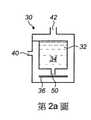
料匣30在第2a圖中被顯示為一個單獨組件,具有大致圓柱形且包括一用以儲存像丙二醇、植物甘油或其組合之氣溶膠形成液體34的儲存器32及一為可感應加熱圓盤之形式的可感應加熱元件36。可感應加 熱元件36係由會在電磁場之存在下因在可感應加熱元件36中所感應之渦流及/或磁滯損耗而變熱之導電材料所形成。料匣30包括一用以將氣溶膠形成液體34從儲存器32輸送至可感應加熱元件36之毛細元件38。毛細元件38係電絕緣且非磁性材料所形成,以及因此,它不會在電磁場之存在下變熱。料匣30亦包括一在內部形成有液體儲存器之殼體41。殼體41具有一空氣入口40及一用以界定使用者可藉以吸入氣溶膠之煙嘴44的出口42。
氣溶膠產生系統10包括一感應加熱裝置24,其包括一可由電源20來供給能量且可由控制裝置18來控制其操作之感應線圈26。如熟悉該項技藝者所了解,當供給能量至該感應線圈26時,產生交變和時變電磁場,此電磁場在該可感應加熱元件36中產生渦流及/或磁滯損耗,以促使該可感應加熱元件36變熱。結果,加熱被毛細元件38輸送至可感應加熱元件36之氣溶膠形成液體34,以及當氣溶膠形成液體34達到它的沸點時,氣溶膠形成液體34會氣化。當使用者經由煙嘴44吸氣時,空氣被吸入該空氣入口40且沿著在殼體41中所界定之通道46流動。氣化的氣溶膠形成液體被夾帶在流經通道46之空氣中且在離開煙嘴44及進入使用者之口中前冷卻成氣溶膠。當在氣溶膠產生系統10之操作期間使從儲存器32被輸送至可感應加熱元件36之液體34氣化時,將了解到,毛細元件38會藉由毛細作用將另外的氣溶膠形成液體34從儲存器32輸送至可感應加熱元件36。The
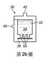
在第1及2a圖所述之料匣30中,毛細元件38包括一毛細管50,其具有與儲存器32中之氣溶膠形成液體34接觸之第一端52及配置成將輸送的液體34轉移至可感應加熱元件36上之相對的第二端54。在一些實施例中,如第2b圖所示,複數個毛細管50係提供以輸送氣溶膠形成液體34。In the
在第2c圖所示之實施例中,使毛細元件50之第二端54與可感應加熱元件36之表面隔開。此間隔決定在可感應加熱元件36之表面上所儲存的氣溶膠形成液體34之數量且此間隔係可以改變的。大體上,毛細管50之第二端54與可感應加熱元件36之表面間的間隔增加了,在可感應加熱元件36上所儲存之氣溶膠形成液體34的數量亦隨之增加。儲存之氣溶膠形成液體34的數量增加了,使用者在氣溶膠產生系統10之操作期間經由煙嘴44吸氣時所產生的氣溶膠之數量亦隨之增加。In the embodiment shown in Figure 2c, the
在第2d圖所示之實施例中,毛細管50之第二端54係配置成與可感應加熱元件36之表面接觸且係被成形或構造成可允許將輸送的液體34從該第二端54轉移至可感應加熱元件36,以便可使其氣化。更特別地,在第2d圖中將可看到,第二端54包括一界定可允許輸送的液體34被轉移至可感應加熱元件36之表面上的出口之切口部分56。從第2d圖將注意到,切口部分56之深度控制在可感應加熱元件36之表面上所儲存的液體34之數量,以及特別地,所儲存的液體34之表面位準係對應於切口部分56之深度。In the embodiment shown in Fig. 2d, the
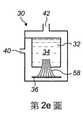
在第2e圖所示之實施例中,毛細元件38包括一含有複數股合適芯吸材料之毛細芯58。In the embodiment shown in Figure 2e, the
在第2f圖所示之實施例中,毛細元件38包括一多孔體60,例如,礦物棉。在此實施例中,將看到,可感應加熱元件36被多孔體60所包封,以致於可感應加熱元件36之上下表面與多孔體60接觸,以及因而,與所輸送之氣溶膠形成液體34接觸。In the embodiment shown in Figure 2f, the
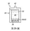
在第2g及2h圖之實施例中,毛細元件38包括陶瓷材料或另一合適固態材料的多孔體62。在第2g圖之料匣30中,可感應加熱元件36之上表面與多孔體62直接接觸,以及因而,與所輸送的氣溶膠形成液體34直接接觸。在第2h圖之料匣中,可感應加熱元件36被多孔體62所包封,以致於可感應加熱元件36之上下兩個表面與多孔體60接觸,以及因而,與所輸送的氣溶膠形成液體34接觸。為了有助於液體及煙霧劑經由多孔體62流動,可感應加熱元件36可以包括如第2h圖所示之一個以上隙孔或穿孔(例如,可感應加熱元件36可以是穿孔圓盤之形式)。In the embodiment of Figures 2g and 2h, the
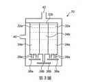
現在參考第3圖,顯示一料匣70,其包括用以分別儲存第一及第二氣溶膠形成液體34a、34b之環形第一儲存器32a及圓筒形第二儲存器32b。料匣70包括與第一及第二儲存器32a、32b之每一者相關聯的第一及第二可感應加熱元件36a、36b以及複數個用以從第一及第二儲存器32a、32b分別輸送第一及第二氣溶膠形成液體34a、34b至對應的第一及二可感應加熱元件36a、36b 之第一毛細元件38a及第二毛細元件38b,以便可藉由第一及第二可感應加熱元件36a、36b使所輸送的第一及第二氣溶膠形成液體氣化。Referring now to Figure 3, a
在第一及第二儲存器32a、32b中所儲存之第一及第二氣溶膠形成液體34a、34b係彼此不同的且具有不同的沸點。在一實施例中,第一氣溶膠形成液體34a係蔬菜甘油且具有約290℃之沸點,而第二氣溶膠形成液體34b係丙二醇且具有約189℃之較低沸點。The first and second aerosol-forming
雖然第3圖係示意圖,但是將可輕易理解到,第一及第二可感應加熱元件36a、36b具有不同尺寸,以及特別地,第一可感應加熱元件36a係大致環形的,其具有比為圓盤之形式的第二可感應加熱元件36b還大之外徑,以及當將料匣70插入第1圖所示之氣溶膠產生系統10的細長體12之空腔22中時,第一可感應加熱元件36a的位置比較靠近感應線圈26。結果,第一可感應加熱元件36a與感應線圈26間之電磁耦合係比第二可感應加熱元件36b與感應線圈26間之電磁耦合還大。上述的結果是,相同的電磁場將第一可感應加熱元件36a加熱至比第二可感應加熱元件36b還高之溫度。藉由合適地構造及配置第一及第二可感應加熱元件36a、36b,將因而了解到,它們被加熱至不同的溫度,而這些不同的溫度被最佳化成用以加熱不同的第一及第二氣溶膠形成液體34a、34b且使它們氣化。雖然已以植物甘油和丙二醇作為第一及第二氣溶膠形成液體34a、34b之實例,但是熟習該項技藝者將可輕易了解到,可使用其它的氣溶膠形成液體。Although FIG. 3 is a schematic diagram, it will be readily appreciated that the first and second inductively
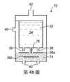
第4a及4b圖說明使用非液體風味釋放介質74與已述類型的氣溶膠形成液體34組合之「混合」料匣72。非液體風味釋放介質74通常包括菸草材料,但是如本說明書前面所述。可使用其它非液體風味釋放介質。非液體風味釋放介質74通常用像丙二醇、甘油或兩者的組合之煙霧劑形成介質來浸漬,以及當被加熱至在一操作溫度範圍內的某一溫度時,它會產生供使用者吸入之煙霧劑。Figures 4a and 4b illustrate a "mixed"
第4a及4b圖所述之料匣72使用相同於上面第3圖所述之料匣70的原理來操作,以加熱第一及第二可感應加熱元件36a、36b至不同溫度。The
首先,更詳細參考第4a圖,藉由複數個毛細元件38將氣溶膠形成液體34從儲存器32輸送至第一可感應加熱元件36a。當在氣溶膠產生系統10之操作期間所輸送的氣溶膠形成液體34接觸第一可感應加熱元件36a之表面時,使所輸送的氣溶膠形成液體34在使用中氣化。非液體風味釋放介質74黏附至第二可感應加熱元件36b之表面。如上面關於圖3所述,在氣溶膠產生系統10之操作期間,將第二可感應加熱元件36b加熱至比第一可感應加熱元件36a還低的溫度,以及因而,加熱非液體風味釋放介質74至最佳溫度,以產生合適的風味及香氣,而不會燃燒或燒焦非液體風味釋放介質74。當使用者經由煙嘴44吸氣時,將了解到,藉由加熱氣溶膠形成液體34所產生之煙霧劑與藉由加熱非液體風味釋放介質74所產生之風味化合物結合成具有最佳風味及 香氣特性及特別是與傳統點燃端香煙之風味及香氣儘可能相似的氣溶膠。First, referring in more detail to Figure 4a, the aerosol-forming
除非液體風味釋放介質74包封在第二可感應加熱元件36b周圍,以取代黏附至它的表面之外,第4b圖之實施例係相似於第4a圖之實施例。在此實施例中,將注意到,兩個空氣入口40係設置在殼體41中且空氣入口40係位於殼體41之遠端,以便最佳化通過非液體風味釋放介質74。The embodiment of Figure 4b is similar to the embodiment of Figure 4a, except that the liquid
將注意到,第4a及4b圖所述之料匣72包括一用以將氣溶膠形成液體34從儲存器32輸送至非液體風味釋放介質74之毛細元件76。此確保非液體風味釋放介質74不會因被加熱而完全變乾,藉此減少燃燒及/或燒焦之可能性及最佳化在加熱過程期間所釋放之風味及香氣。It will be noted that the
作為用以將非液體風味釋放介質併入第4a及4b圖所示之料匣72本身的替代方案,可使用第2及3圖所述之料匣30、70的任一者與包含非液體風味釋放介質84之第5圖所示的膠囊80結合。膠囊80係完全獨立的且與料匣30完全分開。膠囊80包括一包含有已描述類型之非液體風味釋放介質84的外殼82。一個以上可感應加熱元件86係配置在外殼82內且配置成用以在氣溶膠產生系統10之操作期間加熱非液體風味釋放介質84。外殼82之至少一部分包括可透氣材料,以致於空氣可流經外殼82。當使用者經由煙嘴44吸氣時,將了解到,藉由加熱氣溶膠形成液體34所產生之煙霧劑與 藉由加熱非液體風味釋放介質84所產生的風味化合物結合成具有最佳風味及香氣特性及特別是與傳統點燃端香煙之風味及香氣儘可能相似的氣溶膠。合適的膠囊80已被描述於本申請人之早期專利申請案第GB 2527597A號中。As an alternative to incorporating a non-liquid flavor release medium into the
第6圖係第5圖所示之膠囊80及氣溶膠產生系統10之相關感應線圈26的放大圖。氣溶膠產生系統10使用一輔助可感應加熱元件90,此輔助可感應加熱元件90之至少一部分係暴露的或可接近的,以便能例如使用溫度探針(未顯示)來直接測量輔助可感應加熱元件90之溫度。輔助可感應加熱元件90之溫度與在膠囊80內之可感應加熱元件86的溫度間之預定關係使藉由簡單測量輔助可感應加熱元件90之溫度來間接測量可感應加熱元件86之溫度成為可能。FIG. 6 is an enlarged view of the
雖然已描述只與膠囊80相關之輔助可感應加熱元件90的使用,但是將了解到,可使用輔助可感應加熱元件90與第1至4圖所述之料匣30、70的任一者結合,以便能根據輔助可感應加熱元件90之溫度與可感應加熱元件36之溫度間的預定關係來間接測量可感應加熱元件36之溫度。Although the use of the auxiliary inductively
雖在前面段落中已描述示例性實施例,但是應該了解到,可以在沒有脫離所附請求項之範圍下對那些實施例實施各種修改。因此,請求項之廣度及範圍不應侷限於上述示例性實施例。除非另有特別說明,在包括請求項及圖式之本說明書中所揭露的每一特徵可以以適合於相同、等效或相似用途的替代特徵來取代。While exemplary embodiments have been described in the preceding paragraphs, it should be understood that various modifications may be made to those embodiments without departing from the scope of the appended claims. Accordingly, the breadth and scope of the claims should not be limited to the above-described exemplary embodiments. Each feature disclosed in this specification, including the claims and drawings, may be replaced by alternative features suitable for the same, equivalent or similar purpose, unless expressly stated otherwise.
除非上下文另有明確要求,在整個說明書和請求項中,文字「包括」將被解釋為開放性,而不是封閉性或耗竭性的意義;亦即,「包括,但不限於」的意義。Unless the context clearly requires otherwise, throughout the specification and claims, the word "comprising" will be construed in an open, rather than a closed or exhaustive sense; that is, in the sense of "including, but not limited to".
除非在此另有說明或明顯與上下文抵觸,本發明包含上述特徵在其所有可能的變化中的任何組合。The invention encompasses any combination of the above features in all possible variations thereof unless otherwise indicated herein or otherwise clearly contradicted by context.
10‧‧‧氣溶膠產生系統10‧‧‧Aerosol Generation System
12‧‧‧細長體12‧‧‧Slim body
14‧‧‧近端14‧‧‧Proximal
16‧‧‧遠端16‧‧‧Remote
18‧‧‧控制裝置18‧‧‧Control device
20‧‧‧電源20‧‧‧Power
22‧‧‧空腔22‧‧‧Cavity
24‧‧‧感應加熱裝置24‧‧‧Induction heating device
26‧‧‧感應線圈26‧‧‧Induction Coil
30‧‧‧料匣30‧‧‧Carrier
32‧‧‧儲存器32‧‧‧Storage
34‧‧‧氣溶膠形成液體34‧‧‧Aerosol-forming liquids
36‧‧‧可感應加熱元件36‧‧‧Induction heating element
38‧‧‧毛細元件38‧‧‧Capillary element
40‧‧‧空氣入口40‧‧‧Air inlet
41‧‧‧殼體41‧‧‧Shell
42‧‧‧出口42‧‧‧Export
44‧‧‧煙嘴44‧‧‧Cigarette holder
46‧‧‧通道46‧‧‧Channel
50‧‧‧毛細管50‧‧‧Capillary
52‧‧‧第一端52‧‧‧First End
54‧‧‧第二端54‧‧‧Second End
Claims (26)
Translated fromChineseApplications Claiming Priority (3)
| Application Number | Priority Date | Filing Date | Title |
|---|---|---|---|
| GBGB1607839.6AGB201607839D0 (en) | 2016-05-05 | 2016-05-05 | Aerosol generating systems |
| GB1607839.6 | 2016-05-05 | ||
| ??1607839.6 | 2016-05-05 |
Publications (2)
| Publication Number | Publication Date |
|---|---|
| TW201818832A TW201818832A (en) | 2018-06-01 |
| TWI752025Btrue TWI752025B (en) | 2022-01-11 |
Family
ID=56297183
Family Applications (2)
| Application Number | Title | Priority Date | Filing Date |
|---|---|---|---|
| TW110133898ATW202205983A (en) | 2016-05-05 | 2017-05-04 | Aerosol generating systems and method for determining the temperature of at least one induction heatable element in the system |
| TW106114813ATWI752025B (en) | 2016-05-05 | 2017-05-04 | Aerosol generating systems and cartridge for use with the system |
Family Applications Before (1)
| Application Number | Title | Priority Date | Filing Date |
|---|---|---|---|
| TW110133898ATW202205983A (en) | 2016-05-05 | 2017-05-04 | Aerosol generating systems and method for determining the temperature of at least one induction heatable element in the system |
Country Status (11)
| Country | Link |
|---|---|
| US (2) | US11172708B2 (en) |
| EP (2) | EP3760060A1 (en) |
| CN (2) | CN109414068B (en) |
| EA (2) | EA202091952A3 (en) |
| ES (1) | ES2840005T3 (en) |
| GB (1) | GB201607839D0 (en) |
| MY (1) | MY194525A (en) |
| PL (1) | PL3451861T3 (en) |
| SG (1) | SG11201809709UA (en) |
| TW (2) | TW202205983A (en) |
| WO (1) | WO2017191176A1 (en) |
Families Citing this family (44)
| Publication number | Priority date | Publication date | Assignee | Title |
|---|---|---|---|---|
| TWI660685B (en) | 2014-05-21 | 2019-06-01 | 瑞士商菲利浦莫里斯製品股份有限公司 | Electrothermal aerosol generating system and cylinder used in the system |
| GB2527597B (en)* | 2014-06-27 | 2016-11-23 | Relco Induction Dev Ltd | Electronic Vapour Inhalers |
| GB201605102D0 (en) | 2016-03-24 | 2016-05-11 | Nicoventures Holdings Ltd | Mechanical connector for electronic vapour provision system |
| CN206808660U (en) | 2016-10-31 | 2017-12-29 | 深圳市合元科技有限公司 | Electronic cigarette |
| EP3554289B1 (en) | 2016-12-19 | 2023-11-22 | Philip Morris Products S.A. | Aerosol-generating system having a cartridge with a side aperture |
| GB2561867B (en) | 2017-04-25 | 2021-04-07 | Nerudia Ltd | Aerosol delivery system |
| TWI769355B (en)* | 2017-12-29 | 2022-07-01 | 瑞士商傑太日煙國際股份有限公司 | Induction heating assembly for a vapour generating device |
| US10750787B2 (en) | 2018-01-03 | 2020-08-25 | Cqens Technologies Inc. | Heat-not-burn device and method |
| US12201154B2 (en) | 2018-01-03 | 2025-01-21 | Cqens Technologies Inc. | Heat-not-burn device and method |
| CN108402521B (en)* | 2018-02-11 | 2020-07-31 | 安徽集友新材料股份有限公司 | Heating non-combustion device |
| WO2019206900A1 (en)* | 2018-04-24 | 2019-10-31 | Philip Morris Products S.A. | Inductive heating assembly for aerosol generation comprising a susceptor element and a liquid retention element |
| JP7391876B2 (en)* | 2018-04-26 | 2023-12-05 | フィリップ・モーリス・プロダクツ・ソシエテ・アノニム | Heater assembly with heater element separated from liquid source |
| WO2019229046A1 (en)* | 2018-05-31 | 2019-12-05 | Jt International Sa | An aerosol generating article, an aerosol generating system and a method for generating a flavoured aerosol |
| WO2020064876A1 (en) | 2018-09-28 | 2020-04-02 | Philip Morris Products S.A. | Aerosol-generating system providing preferential evaporation of nicotine |
| SG11202103757VA (en) | 2018-10-15 | 2021-05-28 | Juul Labs Inc | Heating element |
| KR102270185B1 (en)* | 2018-12-11 | 2021-06-28 | 주식회사 케이티앤지 | Apparatus for generating aerosol |
| KR102199793B1 (en)* | 2018-12-11 | 2021-01-07 | 주식회사 케이티앤지 | Apparatus for generating aerosol |
| US20220183390A1 (en)* | 2019-03-11 | 2022-06-16 | Nicoventures Trading Limited | Aerosol provision device |
| EP3711606A1 (en)* | 2019-03-21 | 2020-09-23 | Nerudia Limited | Aerosol delivery system |
| EP3711597A1 (en)* | 2019-03-21 | 2020-09-23 | Nerudia Limited | Aerosol delivery system |
| EP3711603A1 (en)* | 2019-03-21 | 2020-09-23 | Nerudia Limited | Aerosol delivery system |
| US12114701B2 (en) | 2019-03-21 | 2024-10-15 | Imperial Tobacco Limited | Aerosol delivery system |
| EP3711595A1 (en)* | 2019-03-21 | 2020-09-23 | Nerudia Limited | Aerosol delivery system |
| PL3747289T3 (en)* | 2019-06-06 | 2022-06-20 | Nvx Labs Gmbh | MICROWAVE HEATING UNIT AND METHOD |
| CN114390898A (en)* | 2019-08-30 | 2022-04-22 | 日本烟草国际股份有限公司 | Vaporizer for electronic cigarette |
| PL4025088T3 (en) | 2019-09-05 | 2024-12-23 | Jt International Sa | Heating status indicator and heating method for aerosol generating device |
| US20210093803A1 (en)* | 2019-09-30 | 2021-04-01 | Infineon Technologies Ag | Electronic inhaler with contactless communication |
| US12414586B2 (en)* | 2019-10-18 | 2025-09-16 | Rai Strategic Holdings, Inc. | Surface acoustic wave atomizer for aerosol delivery device |
| CN114727666A (en)* | 2019-11-26 | 2022-07-08 | 日本烟草国际股份有限公司 | Aerosol generating system |
| GB201917463D0 (en)* | 2019-11-29 | 2020-01-15 | Nicoventures Trading Ltd | Electronic aerosol provision system |
| CA3162544A1 (en) | 2019-12-23 | 2021-07-01 | Pax Labs, Inc. | Vaporizer cartridge |
| US11457665B2 (en)* | 2020-01-16 | 2022-10-04 | Nicoventures Trading Limited | Susceptor arrangement for an inductively-heated aerosol delivery device |
| KR102408180B1 (en)* | 2020-02-25 | 2022-06-13 | 주식회사 케이티앤지 | Cartridge and Aerosol generating device comprising the same |
| CN115551376A (en)* | 2020-04-01 | 2022-12-30 | 尤尔实验室有限公司 | evaporator unit |
| KR102511597B1 (en) | 2020-09-07 | 2023-03-17 | 주식회사 케이티앤지 | Aerosol generating apparatus and cartridge used for the same |
| EP3991582A1 (en)* | 2020-10-29 | 2022-05-04 | JT International SA | An aerosol generating device and an aerosol generating system |
| US20230389611A1 (en)* | 2020-10-29 | 2023-12-07 | Jt International Sa | A Cartridge for an Aerosol Generating Device, an Aerosol Generating Device and an Aerosol Generating System |
| KR20230124632A (en)* | 2020-12-22 | 2023-08-25 | 필립모리스 프로덕츠 에스.에이. | Cartridges for use in aerosol-generating systems |
| KR102593730B1 (en)* | 2021-04-02 | 2023-10-24 | 주식회사 케이티앤지 | Multi cartridge and aerosol-generating apparatus including the same |
| USD1028336S1 (en) | 2021-06-22 | 2024-05-21 | Pax Labs, Inc. | Vaporizer cartridge |
| CN116406823A (en)* | 2021-12-30 | 2023-07-11 | 深圳市合元科技有限公司 | Aerosol providing system and atomizer thereof |
| CN115474717A (en)* | 2022-08-10 | 2022-12-16 | 深圳市拓普联科技术股份有限公司 | Cigarette core temperature measurement assembly, electronic cigarette, temperature measurement method and system and storage medium |
| KR20250122465A (en)* | 2022-12-15 | 2025-08-13 | 필립모리스 프로덕츠 에스.에이. | Hybrid aerosol generating device with a single induction coil |
| CN116473303A (en)* | 2023-03-09 | 2023-07-25 | 深圳市小朋新材料科技有限公司 | A temperature maintenance control circuit for electromagnetic induction heating electronic cigarette set |
Citations (4)
| Publication number | Priority date | Publication date | Assignee | Title |
|---|---|---|---|---|
| US20150223292A1 (en)* | 2012-08-08 | 2015-08-06 | Reckitt & Colman (Overseas) Limited | Device for Evaporating a Volatile Material |
| US20150245669A1 (en)* | 2014-02-28 | 2015-09-03 | Altria Client Services Inc. | Electronic vaping device and components thereof |
| US20150320116A1 (en)* | 2014-05-12 | 2015-11-12 | Loto Labs, Inc. | Vaporizer device |
| TW201600031A (en)* | 2014-05-21 | 2016-01-01 | 菲利浦莫里斯製品股份有限公司 | Aerosol generating system including planar induction coil |
Family Cites Families (19)
| Publication number | Priority date | Publication date | Assignee | Title |
|---|---|---|---|---|
| CN201088138Y (en)* | 2007-09-07 | 2008-07-23 | 中国科学院理化技术研究所 | Electronic cigarette with nanoscale ultra-fine space heating atomization function |
| US8821474B2 (en)* | 2010-02-22 | 2014-09-02 | Microsert Ltd. | Slow release liquid drug delivery device |
| CN103889258B (en)* | 2011-10-27 | 2019-06-21 | 菲利普莫里斯生产公司 | Aerosol generation system with improved aerosol generation |
| CN203369386U (en)* | 2013-05-23 | 2014-01-01 | 红云红河烟草(集团)有限责任公司 | Visual heating atomizing type cigarette |
| CN105473012B (en)* | 2013-06-14 | 2020-06-19 | 尤尔实验室有限公司 | Multiple heating elements with separate vaporizable materials in electronic vaporization equipment |
| CN103519351B (en)* | 2013-10-31 | 2017-02-15 | 红塔烟草(集团)有限责任公司 | Electrical heating cigarette |
| WO2015069914A1 (en) | 2013-11-08 | 2015-05-14 | NWT Holdings, LLC | Portable vaporizer and method for temperature control |
| CN103689812A (en)* | 2013-12-30 | 2014-04-02 | 深圳市合元科技有限公司 | Smoke generator and electronic cigarette with same |
| US9642397B2 (en)* | 2014-03-31 | 2017-05-09 | Westfield Limited (Ltd.) | Personal vaporizer with liquid supply by suction |
| TWI692274B (en)* | 2014-05-21 | 2020-04-21 | 瑞士商菲利浦莫里斯製品股份有限公司 | Induction heating device for heating aerosol to form substrate and method for operating induction heating system |
| TWI667964B (en)* | 2014-05-21 | 2019-08-11 | 瑞士商菲利浦莫里斯製品股份有限公司 | Inductive heating device and system for aerosol-generation |
| TWI670017B (en)* | 2014-05-21 | 2019-09-01 | 瑞士商菲利浦莫里斯製品股份有限公司 | Aerosol-forming substrate and aerosol-delivery system |
| GB2527597B (en) | 2014-06-27 | 2016-11-23 | Relco Induction Dev Ltd | Electronic Vapour Inhalers |
| EP3864979A1 (en) | 2014-07-24 | 2021-08-18 | Altria Client Services LLC | Method of producing a vapor from an electronic vaping device |
| CN204146307U (en)* | 2014-08-12 | 2015-02-11 | 刘水根 | A kind of electronic tobacco evaporator |
| GB201511358D0 (en)* | 2015-06-29 | 2015-08-12 | Nicoventures Holdings Ltd | Electronic aerosol provision systems |
| CN204907924U (en)* | 2015-07-29 | 2015-12-30 | 深圳市合元科技有限公司 | Non - burning type smoking utensil |
| US10104912B2 (en)* | 2016-01-20 | 2018-10-23 | Rai Strategic Holdings, Inc. | Control for an induction-based aerosol delivery device |
| MX2018012098A (en)* | 2016-04-11 | 2019-01-10 | Philip Morris Products Sa | AEROSOL GENERATOR ARTICLE. |
- 2016
- 2016-05-05GBGBGB1607839.6Apatent/GB201607839D0/ennot_activeCeased
- 2017
- 2017-05-03CNCN201780039953.0Apatent/CN109414068B/ennot_activeExpired - Fee Related
- 2017-05-03EPEP20192358.8Apatent/EP3760060A1/ennot_activeWithdrawn
- 2017-05-03PLPL17721635Tpatent/PL3451861T3/enunknown
- 2017-05-03MYMYPI2018704069Apatent/MY194525A/enunknown
- 2017-05-03EPEP17721635.5Apatent/EP3451861B1/ennot_activeNot-in-force
- 2017-05-03CNCN202210395095.6Apatent/CN114587020A/enactivePending
- 2017-05-03WOPCT/EP2017/060507patent/WO2017191176A1/ennot_activeCeased
- 2017-05-03EAEA202091952Apatent/EA202091952A3/enunknown
- 2017-05-03EAEA201892530Apatent/EA037581B1/ennot_activeIP Right Cessation
- 2017-05-03ESES17721635Tpatent/ES2840005T3/enactiveActive
- 2017-05-03USUS16/097,531patent/US11172708B2/enactiveActive
- 2017-05-03SGSG11201809709UApatent/SG11201809709UA/enunknown
- 2017-05-04TWTW110133898Apatent/TW202205983A/enunknown
- 2017-05-04TWTW106114813Apatent/TWI752025B/ennot_activeIP Right Cessation
- 2021
- 2021-11-12USUS17/525,411patent/US20220061397A1/ennot_activeAbandoned
Patent Citations (4)
| Publication number | Priority date | Publication date | Assignee | Title |
|---|---|---|---|---|
| US20150223292A1 (en)* | 2012-08-08 | 2015-08-06 | Reckitt & Colman (Overseas) Limited | Device for Evaporating a Volatile Material |
| US20150245669A1 (en)* | 2014-02-28 | 2015-09-03 | Altria Client Services Inc. | Electronic vaping device and components thereof |
| US20150320116A1 (en)* | 2014-05-12 | 2015-11-12 | Loto Labs, Inc. | Vaporizer device |
| TW201600031A (en)* | 2014-05-21 | 2016-01-01 | 菲利浦莫里斯製品股份有限公司 | Aerosol generating system including planar induction coil |
Also Published As
| Publication number | Publication date |
|---|---|
| EA201892530A1 (en) | 2019-05-31 |
| EP3451861A1 (en) | 2019-03-13 |
| WO2017191176A1 (en) | 2017-11-09 |
| GB201607839D0 (en) | 2016-06-22 |
| TW201818832A (en) | 2018-06-01 |
| ES2840005T3 (en) | 2021-07-06 |
| EA202091952A3 (en) | 2021-03-31 |
| CN109414068B (en) | 2022-05-03 |
| US11172708B2 (en) | 2021-11-16 |
| US20220061397A1 (en) | 2022-03-03 |
| MY194525A (en) | 2022-11-30 |
| CN114587020A (en) | 2022-06-07 |
| TW202205983A (en) | 2022-02-16 |
| EA037581B1 (en) | 2021-04-16 |
| EA202091952A2 (en) | 2020-11-30 |
| US20190142066A1 (en) | 2019-05-16 |
| CN109414068A (en) | 2019-03-01 |
| PL3451861T3 (en) | 2021-04-19 |
| EP3760060A1 (en) | 2021-01-06 |
| EP3451861B1 (en) | 2020-10-28 |
| SG11201809709UA (en) | 2018-11-29 |
Similar Documents
| Publication | Publication Date | Title |
|---|---|---|
| TWI752025B (en) | Aerosol generating systems and cartridge for use with the system | |
| JP7393580B2 (en) | electronic steam inhaler | |
| CN109219360B (en) | Aerosol-generating system including heated aerosol-generating article | |
| EP3740089B1 (en) | Shisha device with active cooling for enhanced aerosol characteristics | |
| JP2023134809A (en) | Aerosol generating system delivering substrate to heater element by using venturi effect | |
| JP2025011290A (en) | Electronic Vapor Inhaler | |
| CN106102490B (en) | Electrically Heated Aerosol Generation System | |
| CN110769885A (en) | Aerosol Delivery System | |
| UA124700C2 (en) | AEROSOL DELIVERY DEVICE WITH IMPROVED FLUID TRANSFER | |
| TWI738899B (en) | Vapor generating device and electronic delivery system for providing nicotine to a user | |
| JP2021525093A (en) | Aerosol-generating articles, aerosol-generating systems, and methods for generating flavored aerosols. | |
| JP2025106617A (en) | Heating Device and Heating System | |
| KR20240113913A (en) | Hybrid aerosol generation system with modular consumables | |
| WO2023148915A1 (en) | Smoking system and flavor inhaler | |
| EA042885B1 (en) | AEROSOL GENERATION SYSTEM | |
| KR20230142531A (en) | Induction heating assembly for aerosol generating device | |
| EA042859B1 (en) | AEROSOL GENERATING PRODUCT, AEROSOL GENERATING SYSTEM AND METHOD FOR GENERATING AROMATIZED AEROSOL | |
| EA043385B1 (en) | ELECTRONIC STEAM INHALER |
Legal Events
| Date | Code | Title | Description |
|---|---|---|---|
| MM4A | Annulment or lapse of patent due to non-payment of fees |