TWI750556B - Lens component fixing device - Google Patents
Lens component fixing deviceDownload PDFInfo
- Publication number
- TWI750556B TWI750556BTW108147200ATW108147200ATWI750556BTW I750556 BTWI750556 BTW I750556BTW 108147200 ATW108147200 ATW 108147200ATW 108147200 ATW108147200 ATW 108147200ATW I750556 BTWI750556 BTW I750556B
- Authority
- TW
- Taiwan
- Prior art keywords
- lens assembly
- fixing device
- unit
- inner frame
- frame unit
- Prior art date
Links
Images


Classifications
- G—PHYSICS
- G02—OPTICS
- G02C—SPECTACLES; SUNGLASSES OR GOGGLES INSOFAR AS THEY HAVE THE SAME FEATURES AS SPECTACLES; CONTACT LENSES
- G02C3/00—Special supporting arrangements for lens assemblies or monocles
- G02C3/003—Arrangements for fitting and securing to the head in the position of use
- G—PHYSICS
- G02—OPTICS
- G02C—SPECTACLES; SUNGLASSES OR GOGGLES INSOFAR AS THEY HAVE THE SAME FEATURES AS SPECTACLES; CONTACT LENSES
- G02C11/00—Non-optical adjuncts; Attachment thereof
- G02C11/12—Side shields for protection of the eyes
- G—PHYSICS
- G02—OPTICS
- G02C—SPECTACLES; SUNGLASSES OR GOGGLES INSOFAR AS THEY HAVE THE SAME FEATURES AS SPECTACLES; CONTACT LENSES
- G02C5/00—Constructions of non-optical parts
- G02C5/12—Nose pads; Nose-engaging surfaces of bridges or rims
- G—PHYSICS
- G02—OPTICS
- G02C—SPECTACLES; SUNGLASSES OR GOGGLES INSOFAR AS THEY HAVE THE SAME FEATURES AS SPECTACLES; CONTACT LENSES
- G02C2200/00—Generic mechanical aspects applicable to one or more of the groups G02C1/00 - G02C5/00 and G02C9/00 - G02C13/00 and their subgroups
- G02C2200/08—Modular frames, easily exchangeable frame parts and lenses
- G—PHYSICS
- G02—OPTICS
- G02C—SPECTACLES; SUNGLASSES OR GOGGLES INSOFAR AS THEY HAVE THE SAME FEATURES AS SPECTACLES; CONTACT LENSES
- G02C9/00—Attaching auxiliary optical parts
- G02C9/04—Attaching auxiliary optical parts by fitting over or clamping on
Landscapes
- Physics & Mathematics (AREA)
- Health & Medical Sciences (AREA)
- General Physics & Mathematics (AREA)
- Ophthalmology & Optometry (AREA)
- Optics & Photonics (AREA)
- Eyeglasses (AREA)
Abstract
Translated fromChineseDescription
Translated fromChinese本發明是有關於一種固定裝置,特別是指一種鏡片組件固定裝置。The present invention relates to a fixing device, in particular to a lens assembly fixing device.
對於眼鏡族而言,運動時身體劇烈顫動且汗流浹背而讓眼鏡滑落,無疑是一大噩夢,因此針對運動時協助固定眼鏡的眼鏡固定裝置也應運而生。For glasses people, it is undoubtedly a nightmare to let the glasses slip off due to violent body tremors and sweating during exercise. Therefore, glasses fixing devices to help fix glasses during exercise also came into being.
參閱圖1,而現有之一眼鏡固定裝置,包含一固定該眼鏡1之一鏡片組件11的內框件2,及一條兩端分別夾接該眼鏡1之二鏡腳12的綁帶件3,藉由該綁帶件3將該眼鏡1固定於使用者頭部,並配合該內框件2,將該眼鏡1及使用者臉部間隔一距離,減少眼鏡1被該綁帶件3固定而過度壓迫臉部所產生的不適。Referring to FIG. 1 , an existing eyeglass fixing device includes an
雖然現有之該眼鏡固定裝置確實能藉由該綁帶件3提供固定眼鏡1的效果,但由於該內框件2及該綁帶件3是彼此獨立的兩個元件,使用者在裝設時需要逐一裝設,才能有效地固定該眼鏡1,也因此該內框件2及該綁帶件3必須同時攜帶,缺少其一都無法發揮功效,因此不論是裝設上或是攜帶上,都將帶來不便利。Although the existing glasses fixing device can indeed provide the effect of fixing the glasses 1 by the
因此,本發明之目的,即在提供一種有效固定鏡片且方便攜帶的鏡片組件固定裝置。Therefore, the purpose of the present invention is to provide a lens assembly fixing device that effectively fixes the lens and is convenient to carry.
於是,本發明鏡片組件固定裝置,該鏡片組件包含一個包括一內表面及一外表面之鏡體,而該鏡片組件固定裝置包含一適用於設置在該鏡體之內表面的內框單元、至少一由該內框單元往該鏡體延伸的卡固單元、二分別一體連接於該內框單元左右兩側的連接單元,及一連接該等連接單元的配戴單元。Therefore, the lens assembly fixing device of the present invention, the lens assembly includes a mirror body including an inner surface and an outer surface, and the lens assembly fixing device includes an inner frame unit suitable for being arranged on the inner surface of the mirror body, at least A clamping unit extending from the inner frame unit to the mirror body, two connecting units integrally connected to the left and right sides of the inner frame unit respectively, and a wearing unit connecting the connecting units.
每一卡固單元包括二分別由該內框單元上下兩側斜向延伸而適用於可脫離地卡設該鏡體的定位件。Each clamping unit includes two positioning pieces respectively extending obliquely from the upper and lower sides of the inner frame unit and suitable for detachably clamping the mirror body.
本發明之功效在於:藉由彼此向該鏡體延伸之該等定位件提供的前後及上下限位力,以及連接該等連接單元的配戴單元,使得本發明鏡片組件固定裝置實質上可視為一體,僅需將該鏡體藉由該至少一卡固單元固定於該內框單元,即可完成組裝,提升裝設及攜帶的方便性,達成有效固定眼鏡且方便攜帶的功效。The effect of the present invention lies in: the front and rear and upper and lower limit forces provided by the positioning members extending toward the lens body from each other, and the wearing units connected with the connecting units, the lens assembly fixing device of the present invention can be regarded as substantially As a whole, the lens body only needs to be fixed to the inner frame unit by the at least one clamping unit to complete the assembly, which improves the convenience of installation and carrying, and achieves the effect of effectively fixing the glasses and being convenient to carry.
在本發明被詳細描述之前,應當注意在以下的說明內容中,類似的元件是以相同的編號來表示。Before the present invention is described in detail, it should be noted that in the following description, similar elements are designated by the same reference numerals.
參閱圖2~4,本發明鏡片組件固定裝置之一第一實施例,該鏡片組件4包含一個包括一內表面411及一外表面412之鏡體41,及二分別由該鏡體41兩側向後延伸的鏡腳42,其中,該鏡體41還包括四貫穿該內表面411及該外表面412的卡槽413。而該第一實施例包含一適用於設置在該鏡體41之內表面411的內框單元5、至少一由該內框單元5往該鏡體41延伸的卡固單元6、二分別一體連接於該內框單元5左右兩側的連接單元7,及一連接該等連接單元7的配戴單元8。Referring to FIGS. 2 to 4 , a first embodiment of the lens assembly fixing device of the present invention, the
該內框單元5包括一呈倒V狀並適用於貼合鼻樑的鼻架件51、二分別由該鼻架件51兩端往該等連接單元7延伸的下框件52,及一個兩端分別連接該等連接單元7的上框件53,其中,該鼻架件51、該等下框件52,及該上框件53相配合形成一可視空間54。而為了兼顧結構強度以及使用者配戴的舒適度,該內框單元5之材質為塑膠、矽膠、橡膠的其中之一或其組合。The
至少一該卡固單元6包括二分別由該內框單元5上下兩側斜向延伸的定位件61。在本實施例中,該卡固單元6的數量是兩組,並分別對稱地設置於該鼻架件51兩側。每一卡固單元6包括二分別由該上框件53及該下框件52斜向延伸的定位件61,以下為了方便說明,將該等定位件61依照設置位置的差異,區分為設置於該上框件53且斜向延伸的上定位件61A,及設置於該下框件52且斜向延伸的下定位件61B。該等下定位件61B分別穿設位於該鏡體41下半部之卡槽413,並直接提供一限制該鏡體41上下左右方向的定位力;該等上定位件61A分別穿設位於該鏡體41上半部之卡槽413,也直接提供限制該鏡體41上下左右方向的定位力,再藉由該等上定位件61A及該等下定位件61B斜向延伸的設計,該等卡固單元6相配合提供一阻止該鏡體41向前移動的擋止力。At least one of the
需要特別說明的是,雖然圖2繪示之該等下定位件61B是斜向往下延伸,但並不以此為限,只要能夠穿設該等卡槽413並產生前述之定位力及擋止力,即屬本發明之專利範圍,故不以圖2繪示之形態為限。It should be noted that, although the
每一連接單元7包括一圍繞界定出一適用於供個別鏡腳42卡設並連通該可視空間54之固定槽71的固定件72。藉由分別設置於該鏡體41左右兩側之該等固定槽71,當該等鏡腳42分別相向地卡設於該等固定槽71時,該等固定件72將相配合提供一阻止該鏡片組件4左右移動的限位力。Each connecting
為了對應每一位使用者不同的頭型,該配戴單元8較佳為鬆緊帶、具有皮帶扣之調整帶的其中之一。且值得一提的是,該配戴單元8實質上是一體連接於該內框單元5,使用時不需要進行額外的組裝,閒置時也不需另外執行元件的拆卸。In order to correspond to the different head shape of each user, the wearing
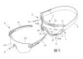
參閱圖3、圖4,藉由上述元件的設置,當使用者將該內框單元5貼合於眼睛周圍,並將該配戴單元8套設於頭部時,僅需依照一般配戴眼鏡的習慣,將該等鏡腳42分別相向地穿設該固定槽71並貼放於耳翼旁,並將該鏡片組件4藉由該等卡固單元6卡設於該內框單元5上,即可完成該第一實施例的裝設,並可作為滑雪鏡、運動眼鏡,或是護目鏡使用。此時該鏡體41將會受到來自該等卡固單元6的前後及上下方向的限位力,連同該等固定件72相配合對於該等鏡腳42提供左右方向的限位力,再結合該配戴單元8施加於該等鏡腳42的迫緊力,達成有效固定鏡片組件4的效果。當需要把鏡片組件4拿下,或是不再需要額外加強固定鏡片組件4時,僅需直接將該配戴單元8拉離使用者頭部,並將該鏡片組件4從該內框單元5上取下,再將該第一實施例摺好收納或是直接掛在脖子上即可,完全不需額外進行元件的拆卸。需要特別說明的是,圖3、圖4是為了方便讀者更容易理解本實施例配戴的方式,但因為人們的頭型大小形狀的差異,實際配戴的角度也有所不同,因此並不以繪示內容為限。Referring to FIGS. 3 and 4 , with the arrangement of the above-mentioned components, when the user attaches the
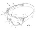
參閱圖5、6,本發明鏡片組件固定裝置之一第二實施例,該第二實施例與該第一實施例的差別在於該鏡體41種類的不同,該第一實施例較佳適用於固定具有鏡框的鏡體41,而該第二實施例則較佳適用於固定沒有鏡框且不具有卡槽的鏡體41。為了有效地達成此功效,該第二實施例之該卡固單元6的該等定位件61是分別由該內框單元5上下兩側相向斜向延伸,設置於該上框件53之該等定位件61定義為上定位件61A,而設置於該下框件52之該等定位件61則定義為下定位件61B,該等上定位件61A提供一阻止該鏡體41向上移動的擋止力,而該等下定位件61B則相配合提供一支撐該鏡體41的頂抵力,並藉由該等上定位件61A及該等下定位件61B斜向並相向延伸的設計,該等卡固單元6相配合提供一阻止該鏡體41向前移動的擋止力。值得一提的是,該卡固單元6還包括二分別由該鼻架件51兩側斜向延伸並適用於卡固該鏡體41的協固件62。藉由該等協固件62,除了提供限制該鏡體41前後移動的前後限位力,還能進一步提供阻擋外在氣流通過的效果,以防止氣流經由不具有鏡框之該鏡體41與該鼻架件51之間的縫隙吹入,進而避免使用者的鼻部受寒而感到不適。Referring to FIGS. 5 and 6 , a second embodiment of the lens assembly fixing device of the present invention, the difference between the second embodiment and the first embodiment lies in the type of the
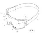
參閱圖7、8,本發明鏡片組件固定裝置之一第三實施例,該第三實施例與該第一實施例及該第二實施例的差別也在於固定之該鏡片組件4種類的不同,該鏡體41還包括二位於上半部並貫穿該內表面411及該外表面412的卡槽413。為了有效固定這類型的眼鏡,該第三實施例之該卡固單元6之該等上定位件61A,將分別穿設且可脫離地卡固於該等卡槽413,而直接相對於該鏡體41提供一限制上下左右方向的定位力,偕同該等下定位件61B,以及設置於該鼻架件51兩側的協固件62,進一步提供限制該鏡體41下半部前後方向的限位力。綜合以上配置,同樣能夠提供有效固定鏡片組件4的效果。7 and 8, a third embodiment of the lens assembly fixing device of the present invention, the difference between the third embodiment and the first embodiment and the second embodiment is also in the type of the
重新參閱圖6、8,值得一提的是,雖然該第一實施例、第二實施例及該第三實施例固定鏡片組件的機制有些不同,在該第二實施例中,該等上定位件61A是以斜向往下延伸來提供限位力;而在該第一實施例及該第三實施例中,該等上定位件61A是分別穿設該等卡槽413來提供定位力。然而,該等上定位件61A實際上並不需要調整結構,只要是斜向往下延伸並可穿設該等卡槽413,即可分別產生提供擋止力或是穿設來提供定位力的效果,如此一來,更進一步提升卡設鏡片組件種類的多樣性。Referring back to FIGS. 6 and 8 , it is worth mentioning that although the first embodiment, the second embodiment and the third embodiment have different mechanisms for securing the lens assembly, in the second embodiment, the upper positioning The
綜上所述,本發明鏡片組件固定裝置,藉由彼此相向延伸之該等定位件61提供之限制前後及上下方向移動的限位力,或是穿設該等卡槽413以提供限制上下左右移動的定位力,配合兩側之該等固定件72提供的左右限位力,以及連接該等連接單元7的配戴單元8,使得本發明鏡片組件固定裝置不論裝設或是攜帶,均無須另外進行組裝或是拆卸,達成有效固定且方便攜帶的功效,並且提供固定多種款式鏡片組件的功效,進一步提升適用性,故確實能達成本發明之目的。To sum up, the lens assembly fixing device of the present invention is provided by the
惟以上所述者,僅為本發明之實施例而已,當不能以此限定本發明實施之範圍,凡是依本發明申請專利範圍及專利說明書內容所作之簡單的等效變化與修飾,皆仍屬本發明專利涵蓋之範圍內。However, the above are only examples of the present invention, and should not limit the scope of the present invention. Any simple equivalent changes and modifications made according to the scope of the application for patent of the present invention and the content of the patent specification are still within the scope of the present invention. within the scope of the invention patent.
4:鏡片組件41:鏡體411:內表面412:外表面413:卡槽42:鏡腳5:內框單元51:鼻架件52:下框件53:上框件54:可視空間6:卡固單元61:定位件61A:上定位件61B:下定位件62:協固件7:連接單元71:固定槽72:固定件8:配戴單元4: Lens components41: Mirror body411: inner surface412: outer surface413: Card slot42: Mirror feet5: Inner frame unit51: nose piece52: Lower frame parts53: Upper frame parts54: Visible Space6: Clamping unit61:
本發明之其他的特徵及功效,將於參照圖式的實施方式中清楚地呈現,其中:圖1是一立體圖,說明現有之一眼鏡固定裝置;圖2是一立體分解圖,說明本發明鏡片組件固定裝置之一第一實施例;圖3是一俯視示意圖,說明該第一實施例裝設一鏡體的狀況;圖4是一側視示意圖,以另一角度說明該第一實施例裝設該鏡體的狀況;圖5是一立體圖,說明本發明鏡片組件固定裝置之一第二實施例;圖6是一立體圖,說明該第二實施例裝設該鏡體的狀況;圖7是一立體分解圖,說明本發明鏡片組件固定裝置之一第三實施例;及圖8是一立體圖,說明該第三實施例裝設該鏡體的狀況。Other features and effects of the present invention will be clearly presented in the embodiments with reference to the drawings, wherein:1 is a perspective view illustrating a conventional eyeglass fixing device;2 is an exploded perspective view illustrating a first embodiment of a lens assembly fixing device of the present invention;FIG. 3 is a schematic top view illustrating a state in which a mirror body is installed in the first embodiment;FIG. 4 is a schematic side view illustrating the state of installing the mirror body in the first embodiment from another angle;5 is a perspective view illustrating a second embodiment of the lens assembly fixing device of the present invention;FIG. 6 is a perspective view illustrating a state in which the mirror body is installed in the second embodiment;7 is an exploded perspective view illustrating a third embodiment of the lens assembly fixing device of the present invention; andFIG. 8 is a perspective view illustrating a state in which the mirror body is installed in the third embodiment.
4:鏡片組件4: Lens components
41:鏡體41: Mirror body
411:內表面411: inner surface
412:外表面412: outer surface
413:卡槽413: Card slot
42:鏡腳42: Mirror feet
5:內框單元5: Inner frame unit
51:鼻架件51: nose piece
52:下框件52: Lower frame parts
53:上框件53: Upper frame parts
54:可視空間54: Visible Space
6:卡固單元6: Clamping unit
61:定位件61: Positioning pieces
61A:上定位件61A: Upper positioning piece
61B:下定位件61B: Lower positioning piece
7:連接單元7: Connection unit
71:固定槽71: Fixed slot
72:固定件72: Fixtures
8:配戴單元8: Wearing unit
Claims (9)
Translated fromChinesePriority Applications (2)
| Application Number | Priority Date | Filing Date | Title |
|---|---|---|---|
| TW108147200ATWI750556B (en) | 2019-12-23 | 2019-12-23 | Lens component fixing device |
| US16/894,936US20210191148A1 (en) | 2019-12-23 | 2020-06-08 | Eyewear attachment and eyewear assembly |
Applications Claiming Priority (1)
| Application Number | Priority Date | Filing Date | Title |
|---|---|---|---|
| TW108147200ATWI750556B (en) | 2019-12-23 | 2019-12-23 | Lens component fixing device |
Publications (2)
| Publication Number | Publication Date |
|---|---|
| TW202125045A TW202125045A (en) | 2021-07-01 |
| TWI750556Btrue TWI750556B (en) | 2021-12-21 |
Family
ID=76438124
Family Applications (1)
| Application Number | Title | Priority Date | Filing Date |
|---|---|---|---|
| TW108147200ATWI750556B (en) | 2019-12-23 | 2019-12-23 | Lens component fixing device |
Country Status (2)
| Country | Link |
|---|---|
| US (1) | US20210191148A1 (en) |
| TW (1) | TWI750556B (en) |
Families Citing this family (1)
| Publication number | Priority date | Publication date | Assignee | Title |
|---|---|---|---|---|
| USD1043781S1 (en)* | 2022-05-02 | 2024-09-24 | Jeffrey Michael Simpson | Insert for safety eyewear |
Citations (6)
| Publication number | Priority date | Publication date | Assignee | Title |
|---|---|---|---|---|
| CN2676234Y (en)* | 2003-12-10 | 2005-02-02 | 张晖 | Wind and sand proof protective spectacles |
| TWM324789U (en)* | 2007-05-23 | 2008-01-01 | Day Sun Ind Corp | Goggles assembly |
| TWI320491B (en)* | 2007-04-30 | 2010-02-11 | Mei Yueh Hou | Multifunctional glasses |
| TWI514025B (en)* | 2014-07-22 | 2015-12-21 | High Rainbow Ent Co | Glasses and assembly method thereof |
| TWI629536B (en)* | 2017-04-11 | 2018-07-11 | 研能科技股份有限公司 | Glasses with wearing cushion device |
| TWI640812B (en)* | 2014-02-04 | 2018-11-11 | 烏菲斯防護用品有限公司 | Goggles |
Family Cites Families (1)
| Publication number | Priority date | Publication date | Assignee | Title |
|---|---|---|---|---|
| US7654666B2 (en)* | 2006-06-06 | 2010-02-02 | 3M Innovative Properties Company | Safety eyewear including a flexible cable attachment |
- 2019
- 2019-12-23TWTW108147200Apatent/TWI750556B/enactive
- 2020
- 2020-06-08USUS16/894,936patent/US20210191148A1/ennot_activeAbandoned
Patent Citations (6)
| Publication number | Priority date | Publication date | Assignee | Title |
|---|---|---|---|---|
| CN2676234Y (en)* | 2003-12-10 | 2005-02-02 | 张晖 | Wind and sand proof protective spectacles |
| TWI320491B (en)* | 2007-04-30 | 2010-02-11 | Mei Yueh Hou | Multifunctional glasses |
| TWM324789U (en)* | 2007-05-23 | 2008-01-01 | Day Sun Ind Corp | Goggles assembly |
| TWI640812B (en)* | 2014-02-04 | 2018-11-11 | 烏菲斯防護用品有限公司 | Goggles |
| TWI514025B (en)* | 2014-07-22 | 2015-12-21 | High Rainbow Ent Co | Glasses and assembly method thereof |
| TWI629536B (en)* | 2017-04-11 | 2018-07-11 | 研能科技股份有限公司 | Glasses with wearing cushion device |
Also Published As
| Publication number | Publication date |
|---|---|
| TW202125045A (en) | 2021-07-01 |
| US20210191148A1 (en) | 2021-06-24 |
Similar Documents
| Publication | Publication Date | Title |
|---|---|---|
| US8182086B2 (en) | Eyeglass frame, eyewear, and an eyewear assembly method | |
| CN102048288A (en) | Sports googles with a sports helmet | |
| US8366267B2 (en) | Spectacle structure | |
| TWI750556B (en) | Lens component fixing device | |
| CN210982938U (en) | Lens Assembly Fixtures | |
| EP1562067B1 (en) | Eyewear | |
| KR20150141801A (en) | Glasses nose angles and height-adjustable stand, and the stand is composed of its nose glasses | |
| US8602553B1 (en) | Apparatus to secure eyewear on user | |
| JP6990238B2 (en) | Eyeglasses with interchangeable lenses | |
| KR20120035349A (en) | Eyeglasses | |
| KR20160003557U (en) | Glasses frame | |
| CN213210625U (en) | glasses frame structure | |
| CN204699333U (en) | Fixing type luntttes | |
| KR102828161B1 (en) | Face fitting and buckle for face fitting | |
| KR102708008B1 (en) | Dog glasses | |
| CN215678937U (en) | Glasses leg and glasses with laminating and ventilation functions | |
| CN201239484Y (en) | Novel swimming goggles | |
| JP2014521406A (en) | goggles | |
| JP3068730U (en) | Swimming goggles | |
| KR20250052832A (en) | Sports goggles | |
| TWM263924U (en) | Security goggles | |
| KR20170069371A (en) | Goggles for vision correction | |
| TWM573238U (en) | Glasses structure | |
| JP3095438U (en) | Pool-specific goggles | |
| JP3095439U (en) | Swimming goggles |