TWI749196B - Anti-counterfeiting element and manufacturing method of anti-counterfeiting element - Google Patents
Anti-counterfeiting element and manufacturing method of anti-counterfeiting elementDownload PDFInfo
- Publication number
- TWI749196B TWI749196BTW107110106ATW107110106ATWI749196BTW I749196 BTWI749196 BTW I749196BTW 107110106 ATW107110106 ATW 107110106ATW 107110106 ATW107110106 ATW 107110106ATW I749196 BTWI749196 BTW I749196B
- Authority
- TW
- Taiwan
- Prior art keywords
- strips
- counterfeiting element
- microstructures
- item
- patent application
- Prior art date
Links
- 238000004519manufacturing processMethods0.000titleclaimsdescription6
- 230000000694effectsEffects0.000claimsabstractdescription115
- 238000000034methodMethods0.000claimsabstractdescription17
- 238000005452bendingMethods0.000claimsdescription43
- 239000013598vectorSubstances0.000claimsdescription37
- 238000010586diagramMethods0.000claimsdescription36
- 230000003287optical effectEffects0.000claimsdescription35
- 230000008859changeEffects0.000claimsdescription25
- 238000005286illuminationMethods0.000claimsdescription12
- 230000005484gravityEffects0.000claimsdescription10
- 238000009826distributionMethods0.000claimsdescription4
- 239000010410layerSubstances0.000description101
- 238000000576coating methodMethods0.000description16
- 229910052751metalInorganic materials0.000description16
- 239000002184metalSubstances0.000description16
- 230000009466transformationEffects0.000description13
- 239000010408filmSubstances0.000description9
- 238000005034decorationMethods0.000description6
- 230000010076replicationEffects0.000description6
- 239000012790adhesive layerSubstances0.000description5
- 230000008569processEffects0.000description5
- 239000011241protective layerSubstances0.000description5
- 239000010409thin filmSubstances0.000description5
- 239000011248coating agentSubstances0.000description4
- 239000000758substrateSubstances0.000description4
- 230000001131transforming effectEffects0.000description4
- 230000008901benefitEffects0.000description3
- 239000010949copperSubstances0.000description3
- 239000004922lacquerSubstances0.000description3
- 239000004973liquid crystal related substanceSubstances0.000description3
- 239000000049pigmentSubstances0.000description3
- RYGMFSIKBFXOCR-UHFFFAOYSA-NCopperChemical compound[Cu]RYGMFSIKBFXOCR-UHFFFAOYSA-N0.000description2
- PXHVJJICTQNCMI-UHFFFAOYSA-NNickelChemical compound[Ni]PXHVJJICTQNCMI-UHFFFAOYSA-N0.000description2
- BQCADISMDOOEFD-UHFFFAOYSA-NSilverChemical compound[Ag]BQCADISMDOOEFD-UHFFFAOYSA-N0.000description2
- 239000005083Zinc sulfideSubstances0.000description2
- 229910052782aluminiumInorganic materials0.000description2
- XAGFODPZIPBFFR-UHFFFAOYSA-NaluminiumChemical compound[Al]XAGFODPZIPBFFR-UHFFFAOYSA-N0.000description2
- 230000004888barrier functionEffects0.000description2
- 239000003086colorantSubstances0.000description2
- 229910052802copperInorganic materials0.000description2
- 239000011159matrix materialSubstances0.000description2
- 150000002739metalsChemical class0.000description2
- 239000002985plastic filmSubstances0.000description2
- 229920006255plastic filmPolymers0.000description2
- 229920000139polyethylene terephthalatePolymers0.000description2
- 239000005020polyethylene terephthalateSubstances0.000description2
- 230000002441reversible effectEffects0.000description2
- 229910052709silverInorganic materials0.000description2
- 239000004332silverSubstances0.000description2
- 238000001228spectrumMethods0.000description2
- 230000007704transitionEffects0.000description2
- 229910052984zinc sulfideInorganic materials0.000description2
- 239000004986Cholesteric liquid crystals (ChLC)Substances0.000description1
- VYZAMTAEIAYCRO-UHFFFAOYSA-NChromiumChemical compound[Cr]VYZAMTAEIAYCRO-UHFFFAOYSA-N0.000description1
- 241000272201ColumbiformesSpecies0.000description1
- GWEVSGVZZGPLCZ-UHFFFAOYSA-NTitan oxideChemical compoundO=[Ti]=OGWEVSGVZZGPLCZ-UHFFFAOYSA-N0.000description1
- 238000010521absorption reactionMethods0.000description1
- 239000000956alloySubstances0.000description1
- 229910045601alloyInorganic materials0.000description1
- 238000000149argon plasma sinteringMethods0.000description1
- 239000011230binding agentSubstances0.000description1
- 230000005540biological transmissionEffects0.000description1
- 210000004556brainAnatomy0.000description1
- 229910052804chromiumInorganic materials0.000description1
- 239000011651chromiumSubstances0.000description1
- 239000011247coating layerSubstances0.000description1
- 238000006073displacement reactionMethods0.000description1
- 238000000609electron-beam lithographyMethods0.000description1
- 238000009713electroplatingMethods0.000description1
- 238000010304firingMethods0.000description1
- 238000005242forgingMethods0.000description1
- 239000012634fragmentSubstances0.000description1
- 239000011521glassSubstances0.000description1
- PCHJSUWPFVWCPO-UHFFFAOYSA-NgoldChemical compound[Au]PCHJSUWPFVWCPO-UHFFFAOYSA-N0.000description1
- 229910052737goldInorganic materials0.000description1
- 239000010931goldSubstances0.000description1
- NLYAJNPCOHFWQQ-UHFFFAOYSA-NkaolinChemical compoundO.O.O=[Al]O[Si](=O)O[Si](=O)O[Al]=ONLYAJNPCOHFWQQ-UHFFFAOYSA-N0.000description1
- 238000001459lithographyMethods0.000description1
- 239000000203mixtureSubstances0.000description1
- 238000012986modificationMethods0.000description1
- 230000004048modificationEffects0.000description1
- 229910052759nickelInorganic materials0.000description1
- 230000000149penetrating effectEffects0.000description1
- 239000004033plasticSubstances0.000description1
- 229920003023plasticPolymers0.000description1
- -1polyethylene terephthalatePolymers0.000description1
- 230000005855radiationEffects0.000description1
- 230000003362replicative effectEffects0.000description1
- 229910052703rhodiumInorganic materials0.000description1
- 230000035945sensitivityEffects0.000description1
- 230000003595spectral effectEffects0.000description1
- 230000003068static effectEffects0.000description1
- 238000000411transmission spectrumMethods0.000description1
- 230000000007visual effectEffects0.000description1
- DRDVZXDWVBGGMH-UHFFFAOYSA-Nzinc;sulfideChemical compound[S-2].[Zn+2]DRDVZXDWVBGGMH-UHFFFAOYSA-N0.000description1
Images


Classifications
- B—PERFORMING OPERATIONS; TRANSPORTING
- B42—BOOKBINDING; ALBUMS; FILES; SPECIAL PRINTED MATTER
- B42D—BOOKS; BOOK COVERS; LOOSE LEAVES; PRINTED MATTER CHARACTERISED BY IDENTIFICATION OR SECURITY FEATURES; PRINTED MATTER OF SPECIAL FORMAT OR STYLE NOT OTHERWISE PROVIDED FOR; DEVICES FOR USE THEREWITH AND NOT OTHERWISE PROVIDED FOR; MOVABLE-STRIP WRITING OR READING APPARATUS
- B42D25/00—Information-bearing cards or sheet-like structures characterised by identification or security features; Manufacture thereof
- B42D25/30—Identification or security features, e.g. for preventing forgery
- B42D25/324—Reliefs
- B—PERFORMING OPERATIONS; TRANSPORTING
- B42—BOOKBINDING; ALBUMS; FILES; SPECIAL PRINTED MATTER
- B42D—BOOKS; BOOK COVERS; LOOSE LEAVES; PRINTED MATTER CHARACTERISED BY IDENTIFICATION OR SECURITY FEATURES; PRINTED MATTER OF SPECIAL FORMAT OR STYLE NOT OTHERWISE PROVIDED FOR; DEVICES FOR USE THEREWITH AND NOT OTHERWISE PROVIDED FOR; MOVABLE-STRIP WRITING OR READING APPARATUS
- B42D25/00—Information-bearing cards or sheet-like structures characterised by identification or security features; Manufacture thereof
- B42D25/30—Identification or security features, e.g. for preventing forgery
- B42D25/328—Diffraction gratings; Holograms
- B—PERFORMING OPERATIONS; TRANSPORTING
- B42—BOOKBINDING; ALBUMS; FILES; SPECIAL PRINTED MATTER
- B42D—BOOKS; BOOK COVERS; LOOSE LEAVES; PRINTED MATTER CHARACTERISED BY IDENTIFICATION OR SECURITY FEATURES; PRINTED MATTER OF SPECIAL FORMAT OR STYLE NOT OTHERWISE PROVIDED FOR; DEVICES FOR USE THEREWITH AND NOT OTHERWISE PROVIDED FOR; MOVABLE-STRIP WRITING OR READING APPARATUS
- B42D25/00—Information-bearing cards or sheet-like structures characterised by identification or security features; Manufacture thereof
- B42D25/30—Identification or security features, e.g. for preventing forgery
- B42D25/337—Guilloche patterns
- B—PERFORMING OPERATIONS; TRANSPORTING
- B42—BOOKBINDING; ALBUMS; FILES; SPECIAL PRINTED MATTER
- B42D—BOOKS; BOOK COVERS; LOOSE LEAVES; PRINTED MATTER CHARACTERISED BY IDENTIFICATION OR SECURITY FEATURES; PRINTED MATTER OF SPECIAL FORMAT OR STYLE NOT OTHERWISE PROVIDED FOR; DEVICES FOR USE THEREWITH AND NOT OTHERWISE PROVIDED FOR; MOVABLE-STRIP WRITING OR READING APPARATUS
- B42D25/00—Information-bearing cards or sheet-like structures characterised by identification or security features; Manufacture thereof
- B42D25/30—Identification or security features, e.g. for preventing forgery
- B42D25/36—Identification or security features, e.g. for preventing forgery comprising special materials
- B42D25/373—Metallic materials
- B—PERFORMING OPERATIONS; TRANSPORTING
- B42—BOOKBINDING; ALBUMS; FILES; SPECIAL PRINTED MATTER
- B42D—BOOKS; BOOK COVERS; LOOSE LEAVES; PRINTED MATTER CHARACTERISED BY IDENTIFICATION OR SECURITY FEATURES; PRINTED MATTER OF SPECIAL FORMAT OR STYLE NOT OTHERWISE PROVIDED FOR; DEVICES FOR USE THEREWITH AND NOT OTHERWISE PROVIDED FOR; MOVABLE-STRIP WRITING OR READING APPARATUS
- B42D25/00—Information-bearing cards or sheet-like structures characterised by identification or security features; Manufacture thereof
- B42D25/40—Manufacture
- B42D25/405—Marking
- B42D25/41—Marking using electromagnetic radiation
- B—PERFORMING OPERATIONS; TRANSPORTING
- B42—BOOKBINDING; ALBUMS; FILES; SPECIAL PRINTED MATTER
- B42D—BOOKS; BOOK COVERS; LOOSE LEAVES; PRINTED MATTER CHARACTERISED BY IDENTIFICATION OR SECURITY FEATURES; PRINTED MATTER OF SPECIAL FORMAT OR STYLE NOT OTHERWISE PROVIDED FOR; DEVICES FOR USE THEREWITH AND NOT OTHERWISE PROVIDED FOR; MOVABLE-STRIP WRITING OR READING APPARATUS
- B42D25/00—Information-bearing cards or sheet-like structures characterised by identification or security features; Manufacture thereof
- B42D25/40—Manufacture
- B42D25/405—Marking
- B42D25/425—Marking by deformation, e.g. embossing
- B—PERFORMING OPERATIONS; TRANSPORTING
- B42—BOOKBINDING; ALBUMS; FILES; SPECIAL PRINTED MATTER
- B42D—BOOKS; BOOK COVERS; LOOSE LEAVES; PRINTED MATTER CHARACTERISED BY IDENTIFICATION OR SECURITY FEATURES; PRINTED MATTER OF SPECIAL FORMAT OR STYLE NOT OTHERWISE PROVIDED FOR; DEVICES FOR USE THEREWITH AND NOT OTHERWISE PROVIDED FOR; MOVABLE-STRIP WRITING OR READING APPARATUS
- B42D25/00—Information-bearing cards or sheet-like structures characterised by identification or security features; Manufacture thereof
- B42D25/40—Manufacture
- B42D25/405—Marking
- B42D25/43—Marking by removal of material
- B—PERFORMING OPERATIONS; TRANSPORTING
- B42—BOOKBINDING; ALBUMS; FILES; SPECIAL PRINTED MATTER
- B42D—BOOKS; BOOK COVERS; LOOSE LEAVES; PRINTED MATTER CHARACTERISED BY IDENTIFICATION OR SECURITY FEATURES; PRINTED MATTER OF SPECIAL FORMAT OR STYLE NOT OTHERWISE PROVIDED FOR; DEVICES FOR USE THEREWITH AND NOT OTHERWISE PROVIDED FOR; MOVABLE-STRIP WRITING OR READING APPARATUS
- B42D25/00—Information-bearing cards or sheet-like structures characterised by identification or security features; Manufacture thereof
- B42D25/40—Manufacture
- B42D25/48—Controlling the manufacturing process
- B42D25/485—Controlling the manufacturing process by electronic processing means
- B—PERFORMING OPERATIONS; TRANSPORTING
- B42—BOOKBINDING; ALBUMS; FILES; SPECIAL PRINTED MATTER
- B42D—BOOKS; BOOK COVERS; LOOSE LEAVES; PRINTED MATTER CHARACTERISED BY IDENTIFICATION OR SECURITY FEATURES; PRINTED MATTER OF SPECIAL FORMAT OR STYLE NOT OTHERWISE PROVIDED FOR; DEVICES FOR USE THEREWITH AND NOT OTHERWISE PROVIDED FOR; MOVABLE-STRIP WRITING OR READING APPARATUS
- B42D25/00—Information-bearing cards or sheet-like structures characterised by identification or security features; Manufacture thereof
- B42D25/20—Information-bearing cards or sheet-like structures characterised by identification or security features; Manufacture thereof characterised by a particular use or purpose
- B42D25/23—Identity cards
- B—PERFORMING OPERATIONS; TRANSPORTING
- B42—BOOKBINDING; ALBUMS; FILES; SPECIAL PRINTED MATTER
- B42D—BOOKS; BOOK COVERS; LOOSE LEAVES; PRINTED MATTER CHARACTERISED BY IDENTIFICATION OR SECURITY FEATURES; PRINTED MATTER OF SPECIAL FORMAT OR STYLE NOT OTHERWISE PROVIDED FOR; DEVICES FOR USE THEREWITH AND NOT OTHERWISE PROVIDED FOR; MOVABLE-STRIP WRITING OR READING APPARATUS
- B42D25/00—Information-bearing cards or sheet-like structures characterised by identification or security features; Manufacture thereof
- B42D25/20—Information-bearing cards or sheet-like structures characterised by identification or security features; Manufacture thereof characterised by a particular use or purpose
- B42D25/24—Passports
- B—PERFORMING OPERATIONS; TRANSPORTING
- B42—BOOKBINDING; ALBUMS; FILES; SPECIAL PRINTED MATTER
- B42D—BOOKS; BOOK COVERS; LOOSE LEAVES; PRINTED MATTER CHARACTERISED BY IDENTIFICATION OR SECURITY FEATURES; PRINTED MATTER OF SPECIAL FORMAT OR STYLE NOT OTHERWISE PROVIDED FOR; DEVICES FOR USE THEREWITH AND NOT OTHERWISE PROVIDED FOR; MOVABLE-STRIP WRITING OR READING APPARATUS
- B42D25/00—Information-bearing cards or sheet-like structures characterised by identification or security features; Manufacture thereof
- B42D25/20—Information-bearing cards or sheet-like structures characterised by identification or security features; Manufacture thereof characterised by a particular use or purpose
- B42D25/29—Securities; Bank notes
Landscapes
- Engineering & Computer Science (AREA)
- Manufacturing & Machinery (AREA)
- Physics & Mathematics (AREA)
- Health & Medical Sciences (AREA)
- Electromagnetism (AREA)
- General Health & Medical Sciences (AREA)
- Toxicology (AREA)
- Business, Economics & Management (AREA)
- Accounting & Taxation (AREA)
- Finance (AREA)
- Credit Cards Or The Like (AREA)
- Diffracting Gratings Or Hologram Optical Elements (AREA)
- Holo Graphy (AREA)
- Stereoscopic And Panoramic Photography (AREA)
- Illuminated Signs And Luminous Advertising (AREA)
Abstract
Translated fromChineseDescription
Translated fromChinese本發明係關於一種防偽元件以及一種防偽元件的製造方法。The invention relates to an anti-counterfeiting element and a manufacturing method of the anti-counterfeiting element.
按,目前防偽元件有許多不同的設計。防偽元件特別是用來產生防偽效果,以及標記出物件的真實性。防偽元件進一步特別用於增加操縱的難度,尤其是增加偽造物件的難度。在身分證明文件等防偽文件領域和紙鈔等有價文件領域內,防偽元件尤其十分重要。According to, there are many different designs of anti-counterfeiting components. Anti-counterfeiting elements are especially used to produce anti-counterfeiting effects and mark the authenticity of objects. The anti-counterfeiting element is further particularly used to increase the difficulty of manipulation, especially to increase the difficulty of forging an object. Anti-counterfeiting components are particularly important in the field of anti-counterfeiting documents such as identity documents and valuable documents such as banknotes.
本發明之目的,在於提供一種改良的防偽元件以及一種改良的防偽元件製造方法,該防偽元件具有特別良好的視覺效果。The purpose of the present invention is to provide an improved anti-counterfeiting element and an improved manufacturing method of the anti-counterfeiting element, which has particularly good visual effects.
為達到上述目的,本發明提供一種如申請專利範圍第1項所述之防偽元件,以及一種如申請專利範圍第63項所述之方法。In order to achieve the above objective, the present invention provides an anti-counterfeiting element as described in
所述防偽元件及方法的特徵在於,提供或製造一個或多個第一微結構,該等第一微結構分別設於一條或多條至少有部分區段形成彎曲的條帶內,或設於一條帶內一個或多個至少有部分區段形成彎曲的區段內,及/或分別沿著一條或多條至少有部分區段形成彎曲的條帶或沿著一條條帶內一個或多個至少有部分區段形成彎曲的區段延伸。The anti-counterfeiting element and method are characterized in that one or more first microstructures are provided or manufactured, and the first microstructures are respectively arranged in one or more strips with at least partial sections forming a curve, or arranged in One or more in one or more at least partial sections in a curved section, and/or along one or more at least partial sections to form a curved strip or one or more in one or more strips At least part of the section forms a curved section extension.
這樣的防偽元件,其製造方法的特徵在於,提供一個檔案,該檔案包含一個或多個像元的像點,該檔案包含所述像點的位置安排,從該像點位置安排決定一條或多條至少有部分區段形成彎曲的條帶,或一條或多條條帶內一個或多個至少有部分區段形成彎曲的區段,在該條帶或該等條帶或條帶的各區段內,分別設有一個或多個第一微結構,該等第一微結構在曝光時提供一個第一光學可變資訊,尤其是提供一個或多個立體效果及/或移動效果,較佳地提供無色或單色的立體效果及/或移動效果。The manufacturing method of such anti-counterfeiting element is characterized by providing a file containing one or more pixels of the image point, the file including the position arrangement of the image point, from the imageThe point position arrangement determines that one or more strips with at least partial sections form a bend, or one or more sections with at least partial sections form a bend in one or more strips. In each section of the band or strip, one or more first microstructures are respectively provided, and these first microstructures provide a first optically variable information during exposure, especially one or more three-dimensional effects and /Or moving effect, preferably providing a colorless or monochromatic three-dimensional effect and/or moving effect.
藉此,可以檢驗防偽元件的真實性,以進一步提升防偽元件的防偽效果。Thereby, the authenticity of the anti-counterfeiting element can be checked, so as to further improve the anti-counterfeiting effect of the anti-counterfeiting element.
很意外地,透過本發明可以使一個或多個像元產生一個或多個視覺上吸引人的、強烈的移動效果、變形(morphing)效果及/或翻轉(flip)效果,及/或使一個或多個像元產生一個或多個視覺上吸引人的、強烈的立體移動效果、立體變形效果及/或立體翻轉效果。依照結構的選擇,還可以進一步讓所述效果較佳地呈現無色或單色。所謂變形(morphing)效果,是指將一個圖案改變、轉換或轉變成另一個圖案,其中這個改變、轉換或轉變過程可以有多個中間階段。所謂翻轉(flip)效果,尤其是指將一個圖案轉變成另一個圖案,而此轉變過程尤其沒有中間階段。Surprisingly, through the present invention, one or more pixels can produce one or more visually attractive, strong movement effects, morphing effects and/or flip effects, and/or make one Or multiple pixels produce one or more visually attractive and strong three-dimensional movement effects, three-dimensional deformation effects and/or three-dimensional flip effects. According to the choice of structure, the effect can be further made colorless or monochromatic. The so-called morphing effect refers to changing, transforming, or transforming a pattern into another pattern, and the changing, transforming, or transforming process can have multiple intermediate stages. The so-called flip effect, in particular, refers to the transformation of one pattern into another pattern, and there is no intermediate stage in this transformation process.
本發明有利的結構設計,請見各附屬項。For the advantageous structural design of the present invention, please refer to the appended items.
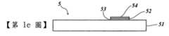
防偽元件會產生人類觀看者可以感知的資訊,這個資訊可以是光學上可變化的。所謂的光學可變性,是指資訊的光學外表會因為觀看角度及/或照明角度不同而有所變化。防偽元件,尤其是光學防偽元件,在此最好是由轉印膜的轉移層、層壓膜或薄膜件組成,或該防偽元件可以直接設於物件表面內。所述防偽元件,尤其是光學防偽元件,在此較佳地係施覆於防偽文件的表面上,或至少有部分嵌設於該防偽文件內。The anti-counterfeiting element generates information that can be perceived by human viewers, and this information can be optically changeable. The so-called optical variability means that the optical appearance of the information will change due to different viewing angles and/or illumination angles. The anti-counterfeiting element, especially the optical anti-counterfeiting element, is preferably composed of a transfer layer of a transfer film, a laminated film or a thin film, or the anti-counterfeiting element can be directly arranged in the surface of the object. The anti-counterfeiting element, especially the optical anti-counterfeiting element, is preferably applied to the surface of the anti-counterfeiting document, or at least partially embedded in the anti-counterfeiting document.
該等第一微結構較佳地在使用光觀看的情況下,會產生一個或多個由人類觀看者或機械可以感知的光學效果。肉眼可以感覺到的波長介於電磁波波譜380nm(紫色)與780nm(深紅色)之間,肉眼對於波長在430nm以下和690nm以上的光線的相對敏感度,只有波長555nm處最大值的1%。因此,在光譜範圍380~430nm以及690~780nm內,只有很強的光源,例如很亮的LED或雷射光,才能被感覺到。These first microstructures preferably produce one or more optical effects that can be perceived by human viewers or machines when viewed with light. The wavelength that the naked eye can perceive is betweenIn the electromagnetic spectrum between 380nm (purple) and 780nm (dark red), the relative sensitivity of the naked eye to light with wavelengths below 430nm and above 690nm is only 1% of the maximum value at 555nm. Therefore, in the spectral range of 380~430nm and 690~780nm, only strong light sources, such as very bright LEDs or lasers, can be felt.
該等第一微結構較佳地共同提供一個第一光學可變資訊,所述第一光學可變資訊最好包含一個或多個立體效果及/或移動效果,而這些效果較佳地為無色或單色。如果是無色效果,則不會出現任何或幾乎沒有繞射顏色效果,而各像元對人類觀看者而言是呈現白色或帶點灰色、平光或金屬亮光。如果是單色效果,像元會顯示一個大致上單色的外表,尤其不會顯示出「一般」繞射結構會出現的彩虹效果。The first microstructures preferably collectively provide a first optically variable information. The first optically variable information preferably includes one or more three-dimensional effects and/or movement effects, and these effects are preferably colorless Or monochrome. If it is a colorless effect, there will be no or almost no diffractive color effect, and each pixel appears white or slightly gray, flat or metallic to the human viewer. If it is a monochromatic effect, the pixel will display a generally monochromatic appearance, especially the rainbow effect that would appear with the "normal" diffraction structure.
所述第一光學可變的資訊,最好具有一個或多個像元,這些像元較佳地由多個像點組成。在此,該等像點分別較佳地由設於不同條帶內或沿個不同條帶延伸的第一微結構提供。The first optically variable information preferably has one or more image elements, and these image elements are preferably composed of a plurality of image points. Here, the image points are preferably provided by the first microstructures arranged in or extending along different strips, respectively.
所以,像元的像點分別由一個或多個第一微結構提供,所述第一微結構因為設置於一個或多個條帶內或一個或多個條帶的區段內,而在預定的觀看方向及/或照明方向下,散射、反射或繞射入射光,進而提供所述圖點。Therefore, the image points of the pixel are respectively provided by one or more first microstructures, and the first microstructures are arranged in one or more strips or within one or more strip sections, and are in a predetermined In the viewing direction and/or illumination direction, the incident light is scattered, reflected or diffracted to provide the image points.
因此,一個或多個像元的每個像點最好由被分配到的第一微結構其中之一提供,且被分配到的第一微結構中每一個都設於所述一條或多條條帶其中一條分別被分配到的條帶內,或被分配到的第一微結構中每一個都沿著一條各自所屬的條帶延伸。在此,最好是讓一個像元的每個像點都分配到所述一條或多條條帶中一條不相同的條帶。而分配給各條帶的微結構更佳地設計成,在防偽元件翻轉及/或彎曲及/或旋轉時,所述像點在使用至少一光源,較佳地使用一個點狀光源照明的情況下,沿著所屬的條帶移動。在此,如果只使用一個光源進行照明,較佳地每條條帶只顯現出一個像點。Therefore, each image point of one or more pixels is preferably provided by one of the assigned first microstructures, and each of the assigned first microstructures is set in the one or more One of the strips is allocated to the strip, or each of the first microstructures allocated to each extends along a strip to which it belongs. Here, it is best to assign each image point of a pixel to a different strip in the one or more strips. The microstructures assigned to each strip are better designed such that when the anti-counterfeiting element is turned and/or bent and/or rotated, the image point uses at least one light source, preferably a point-shaped light source for illumination. Down, move along the band it belongs to. Here, such asIf only one light source is used for illumination, preferably only one image point appears per strip.
所提供的該一或該等第一微結構,最好是讓一個或多個像元的該等像點較佳地在彼此保持恆定距離的情況下相互移動。在此,所述像點尤其是在彼此耦接或相對耦合的情況下移動或活動,其中,該像元最好是不會改變。The one or the first microstructures provided are preferably such that the image points of one or more pixels preferably move with each other while keeping a constant distance from each other. Here, the image points move or move especially when they are coupled to each other or relatively coupled, wherein the image element preferably does not change.
不過,所提供的該一或該等第一微結構,也可以讓各像點之間的距離較佳地可以改變。尤其是各像點的安排可以只在一個狹窄的觀看角度區內顯示該像元。如果相反地,在這個狹窄的觀看角度區外觀看該防偽元件,則該等像點尤其是隨機排列,這個排列尤其不是顯示該像元,而是較佳地以點雲(point cloud)型態呈現。However, the provided one or the first microstructures can also allow the distance between the image points to be preferably changed. In particular, the arrangement of the image points can only display the pixel in a narrow viewing angle area. If, on the contrary, the anti-counterfeiting element is viewed outside this narrow viewing angle area, the image points are especially randomly arranged. This arrangement especially does not display the pixel, but is preferably in the form of a point cloud. Present.
所謂「彎曲」,尤其是指藉由施加外力,使防偽元件以一種特定的方式變形。因此,所謂使防偽元件「彎曲」,尤其是指施加外力到防偽元件上,防偽元件的形狀因為受到力的作用而改變或可改變。一個彎曲的防偽元件相較於沒有彎曲的防偽元件,其幾何產生了改變,尤其是產生了彎曲。The so-called "bending" especially refers to the deformation of the anti-counterfeiting element in a specific way by applying an external force. Therefore, the so-called "bending" of the anti-counterfeiting element especially refers to applying an external force to the anti-counterfeiting element, and the shape of the anti-counterfeiting element changes or can be changed due to the force. Compared with a non-curved anti-counterfeiting element, the geometry of a curved anti-counterfeiting element has been changed, especially bending.
在使防偽元件翻轉及/或彎曲及/或旋轉的期間,各像點在一個恆定的角度速度下沿著各條帶移動的移動速度,在這裡可以一樣或彼此不一樣,及/或各像點可以有不同的移動速度歷程。透過對應地選擇各字條帶上像點的移動速度及/或移動速度歷程,可以產生有趣的光學可變效果,當作第一光學可變資訊。可以透過對應地選擇分別設於各條帶上及/或各條帶區段上的微結構,決定各像點的空間安排與空間走向。藉此,尤其藉由使具有該至少一條帶的防偽元件產生一次或多次旋轉及/或彎曲及/或翻轉,經由一個或多個任意的軸,由一位觀看者登錄下分別沿著該至少一條帶設置的該等像元其中一個或多個的一個或多個移動效果,尤其是光學移動效果。尤其是繞著一個或多個垂直於防偽元件的平面的軸進行一次或多次旋轉時,及/或繞著一個或多個軸進行一次或多次翻轉時,及/或繞著一個或多個該防偽元件平面上以及各第一微結構平面上及/或軌道平面上的軸進行一次或多次彎曲時,可以由一位觀看者登錄下這類移動效果。此外,一個或多個移動效果尤其可以分別是無色及/或單色,及/或隨著照明角度及/或觀看角度而改變的移動效果。During the period of turning and/or bending and/or rotating the anti-counterfeiting element, the moving speed of each image point along each strip at a constant angular speed, here may be the same or different from each other, and/or each image Points can have different movement speed history. By correspondingly selecting the moving speed and/or moving speed history of the image points on each character strip, an interesting optically variable effect can be produced, which can be regarded as the first optically variable information. The spatial arrangement and spatial orientation of each image point can be determined by correspondingly selecting the microstructures respectively arranged on each strip and/or each strip section. Thereby, especially by causing the anti-counterfeiting element with the at least one band to rotate and/or bend and/or flip one or more times, through one or more arbitrary axes, a viewer can register along the At least one set of one or more movement effects of one or more of the pixels, especially optical movement effects. Especially when one or more rotations around one or more axes perpendicular to the plane of the anti-counterfeiting element, and/or around one orWhen multiple shafts are flipped one or more times, and/or when one or more axes on the plane of the anti-counterfeiting element and on the plane of each first microstructure and/or on the track plane are bent one or more times, This type of mobile effect is logged by a viewer. In addition, the one or more movement effects may be colorless and/or monochromatic, respectively, and/or movement effects that change with the illumination angle and/or the viewing angle.
此外,尤其在使防偽元件翻轉及/或彎曲及/或旋轉時,可以由該等第一微結構提供一個像元順序,這些像元會產生一種移動效果、一種變形效果及/或一種翻轉效果。此外,較佳地在使防偽元件翻轉及/或彎曲及/或旋轉時,可以由該等第一微結構提供一個像元順序,這些像元會產生一種立體移動效果、一種立體變形效果及/或一種立體翻轉效果。在此,較佳地,係在使防偽元件翻轉及/或彎曲及/或旋轉時,如前面所述,藉由像點沿著各條帶移動而產生上述之像元順序。In addition, especially when the anti-counterfeiting element is turned and/or bent and/or rotated, the first microstructures can provide a sequence of pixels, and these pixels will produce a movement effect, a deformation effect and/or a flip effect . In addition, preferably when the anti-counterfeiting element is turned and/or bent and/or rotated, the first microstructures can provide a sequence of pixels, and these pixels will produce a three-dimensional movement effect, a three-dimensional deformation effect, and/or a three-dimensional deformation effect. Or a three-dimensional flip effect. Here, preferably, when the anti-counterfeiting element is turned and/or bent and/or rotated, as described above, the above-mentioned pixel sequence is generated by moving the image points along each strip.
由所述各第一微結構所產生的像點,可以形成各式各樣的外型。這些像點較佳地形成一個圓盤形或橢圓形。The image points generated by the first microstructures can be formed into various shapes. These image points preferably form a disc shape or an ellipse shape.
在此,所選擇的個別像點的尺寸,較佳地為能讓沒有穿戴輔具的肉眼可以感覺到像點。其中,像點的側邊尺寸較佳地介於200~500μm之間,更佳地介於200~300μm之間。不過,像點的側邊尺寸進一步也可以在肉眼解析能力以下,這樣一來可以產生特別高的像元解析度。在此情況下,像點的側邊尺寸較佳地介於20~200μm之間,更佳地介於75~200μm之間。由沒有穿戴輔具的肉眼所感覺到像點大小,在此可能與像點的真實大小有所不同。例如,發亮的像點感覺起來可能比較大。如此一來,尤其是真實大小在沒有穿戴輔具的肉眼的解析能力以下的像點,可以被感覺到。在這一點上,較佳地,由內設有第一微結構的各條帶的寬度決定所述像點的側邊尺寸其中至少一個,所述第一微結構產生各像點。較佳地,透過選擇分配到的第一微結構的結構參數,決定該像點的其它側邊尺寸。Here, the size of the selected individual image points is preferably such that the image points can be sensed by the naked eye without an auxiliary device. Among them, the side size of the image point is preferably between 200 and 500 μm, and more preferably between 200 and 300 μm. However, the side size of the pixel can be further lower than the resolution of the naked eye, so that a particularly high pixel resolution can be produced. In this case, the side size of the image point is preferably between 20 and 200 μm, and more preferably between 75 and 200 μm. The size of the image point felt by the naked eye without the aid, here may be different from the actual size of the image point. For example, bright image points may feel larger. In this way, the image points whose real size is below the resolution ability of the naked eye without the aid can be felt. In this regard, preferably, at least one of the side dimensions of the image point is determined by the width of each strip in which the first microstructure is provided, and each image point is generated by the first microstructure. Preferably, by selecting the assigned structural parameters of the first microstructure, the other side dimensions of the image point are determined.
可以將該等像點其中兩個或多個彼此相間而設,像點的間距,較佳地介於5~300μm之間,更佳地介於10~200μm之間,這樣的設置結果使這些像點無法被沒有穿戴輔具的肉眼解析。Two or more of the isoimage points can be arranged alternately with each other. The distance between the image points is preferably between 5 and 300 μm, and more preferably between 10 and 200 μm. This setting results in these The image point cannot be resolved by the naked eye without an assistive device.
所謂的像點間距,在此較佳地是指像點的外緣之間的距離。較佳地,由被分配到的條帶的相對應間距,來決定所述像點間距,所述被分配到的條帶會產生各自的像點。The so-called pixel pitch here preferably refers to the distance between the outer edges of the image points. Preferably, the pixel pitch is determined by the corresponding pitch of the allocated strips, and the allocated strips will generate respective image dots.
此外,也可以將像點間距設計得讓個別像點可以被肉眼解析。在這種情況下,像點間距較佳地大於300μm,更佳地大於500μm。In addition, the pixel pitch can also be designed so that individual image points can be resolved by the naked eye. In this case, the pixel pitch is preferably greater than 300 μm, more preferably greater than 500 μm.
有利的是,該等像元其中一個或多個可以分別是一個圖案、一個以圖形表現的輪廓、一個圖示、一個圖像、一個視覺上可辨識的圖像、一個符號、一個標誌、一個人像、一個花紋、一個字母數字記號、一段文字及/或計類似的內容等。Advantageously, one or more of the pixels can be a pattern, a graphical outline, an icon, an image, a visually recognizable image, a symbol, a logo, and a person. Image, a pattern, an alphanumeric symbol, a paragraph of text and/or similar content, etc.
特別較佳地,在使防偽元件翻轉及/或彎曲及/或旋轉時,該像元的個別像點也可沿著相對於條帶及/或各條帶上速度而言不同的移動方向移動。像元的移動效果尤其是可以隨著繞著一個任意定向的軸所進行的旋轉而改變。Particularly preferably, when the anti-counterfeiting element is turned and/or bent and/or rotated, the individual image points of the pixel can also move along different moving directions relative to the strips and/or the speed on each strip . In particular, the moving effect of the pixel can be changed with the rotation around an arbitrarily oriented axis.
尤其一種變換(transformation),尤指一種變形(morphing),較佳地一種翻轉(flip),可以提供至少一種像元順序,觀看者可以感知到這樣的像元順序,將這個順序當作移動效果、變換效果及/或變形效果。In particular, a transformation, especially a morphing, preferably a flip, can provide at least one pixel sequence, and the viewer can perceive such pixel sequence and regard this sequence as a movement effect , Transformation effect and/or deformation effect.
較佳地,可以將一個或多個條帶及/或複數個第一微結構配置在一起,而可提供一種變換(transformation),尤指所述變形(morphing),較佳地所述翻轉(flip),作為一個像元到另一個或另外多個像元的順序。Preferably, one or more strips and/or a plurality of first microstructures can be arranged together to provide a transformation (transformation), especially the morphing, preferably the reversal ( flip), as the order of one pixel to another or multiple pixels.
尤其將防偽元件繞著任何一軸旋轉及/或彎曲及/或翻轉一次,可以提供一種像元順序,觀看者可以感知到這樣的像元順序,將這個順序當作移動效果、變換效果及/或變形效果。這個也適用於說明立體移動效果、立體變換效果及/或立體變形效果。In particular, rotating and/or bending and/or flipping the anti-counterfeiting element around any axis once can provide a pixel sequence. The viewer can perceive such a pixel sequence and regard this sequence asFor movement effects, transformation effects and/or deformation effects. This also applies to the description of the three-dimensional movement effect, the three-dimensional transformation effect and/or the three-dimensional deformation effect.
所述變換(transformation),尤指所述變形(morphing),較佳地所述翻轉(flip),最好可以提供至少一種觀看者可以感知到的無色或單色移動效果、變換效果及/或變形效果,及/或至少一種隨著至少一照明角度及/或觀看角度而改變的移動效果、變換效果及/或變形效果,所述效果係沿著各條帶及/或第一微結構產生。The transformation, especially the morphing, preferably the flip, preferably can provide at least one colorless or monochromatic movement effect, transformation effect and/or perceivable by the viewer Deformation effect, and/or at least one movement effect, transformation effect and/or deformation effect that changes with at least one illumination angle and/or viewing angle, the effect is generated along each strip and/or the first microstructure .
如果該防偽元件具有數字「4」和數字「2」,則在將防偽元件翻轉及/或彎曲及/或旋轉時,數字「4」可能會轉變為數字「2」,及/或相反。If the anti-counterfeiting element has the number "4" and the number "2", when the anti-counterfeiting element is turned over and/or bent and/or rotated, the number "4" may be changed to the number "2", and/or vice versa.
此外,該防偽元件可以僅包含一條條帶。若用一光源照明該條帶,則較佳地有一個像點可以讓觀看者感覺到,在使防偽元件繞著任一軸旋轉及/或彎曲及/或翻轉時,這個像點會提供至少一種移動效果,尤其是至少一種隨著一照明角度及/或觀看角度而改變的移動效果,所述效果係沿著該條帶產生。In addition, the anti-counterfeiting element may include only one strip. If a light source is used to illuminate the strip, there is preferably an image point that can be felt by the viewer. When the anti-counterfeiting element is rotated and/or bent and/or turned around any axis, this image point will provide at least one The movement effect, especially at least one movement effect that changes with a lighting angle and/or viewing angle, is generated along the strip.
所述防偽元件較佳地包含複數條條帶,該等條帶包含複數個第一微結構。如上所述,藉此,尤其與條帶數目相對應的像點數目可以被觀看者感知,所述像點提供一個或多個像元。The anti-counterfeiting element preferably includes a plurality of strips, and the strips include a plurality of first microstructures. As described above, by this, the number of image points corresponding to the number of strips in particular can be perceived by the viewer, and the image points provide one or more pixels.
此外,也可以將所述防偽元件設計為使用複數個光源照明所述防偽元件。在此,很典型地,會提供每條條帶及/或每個第一微結構一個對應於該等光源的像點數目,這些像點共同提供一個或多個觀看者可感知到的像元。In addition, the anti-counterfeiting element can also be designed to use a plurality of light sources to illuminate the anti-counterfeiting element. Here, typically, each strip and/or each first microstructure is provided with a number of image points corresponding to the light sources, and these image points together provide one or more pixels perceivable by the viewer .
藉此,可以產生其它有趣的光學效果。所以,最簡單的情況下,如果同時用不同的點狀光源進行照明,前面已描述過的光學效果有可能會出現好幾次。此外,在此如果在不同的角度下,用不同的點狀光源進行照射,則也有可能由該防偽元件產生不同的光學可變效果,如此一來,該防偽元件可提供其它很難偽造的防偽特徵以及特別是所謂的「第二條線」(second line)。所謂的「第二條線」防偽特徵,尤其是指僅能用一種輔助工具辨別出及/或證明的特徵。這裡所需要的輔助工具是一般常用的技術器具,例如放大鏡或紫外線燈具。In this way, other interesting optical effects can be produced. Therefore, in the simplest case, if different point light sources are used for illumination at the same time, the optical effects described above may appear several times. In addition, if you use different point light sources to illuminate at different angles, thenIt is also possible that the anti-counterfeiting element can produce different optically variable effects. In this way, the anti-counterfeiting element can provide other anti-counterfeiting features that are difficult to counterfeit, and especially the so-called "second line". The so-called "second line" anti-counterfeiting features especially refer to features that can only be identified and/or proven with one auxiliary tool. The auxiliary tools needed here are commonly used technical appliances, such as magnifying glasses or ultraviolet lamps.
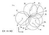
所謂條帶,尤其是指具有寬度,最好具有不變寬度的平面狀區域,條帶係順著一個至少有部分區段呈彎曲的曲線前進,該曲線較佳地為橢圓形、圓形、螺旋形及/或圓弧形,其中,該曲線尤其可以是開放或封閉的,尤其是一條封閉曲線的一個子區可以是開放或封閉的。在另一有利的結構設計,該條帶及/或該條帶的一個或多個輪廓係順著一條一側呈彎曲的曲線前進,使得尤其該曲率的跡象(leading sign)到處都一樣,使得特別是至少一曲線的曲率不會改變跡象。The so-called strip, in particular, refers to a flat area with a width, preferably a constant width, and the strip follows a curved curve with at least a partial section, which is preferably elliptical, circular, or elliptical. Spiral shape and/or circular arc shape, wherein the curve can especially be open or closed, especially a sub-region of a closed curve can be open or closed. In another advantageous structural design, the strip and/or one or more contours of the strip advance along a curve curved on one side, so that the leading sign of curvature is the same everywhere, so that In particular, the curvature of at least one curve does not change signs.
所謂的曲率,尤其是指一條曲線局部偏離直線的程度。所謂的曲線的曲率,尤其是指一段夠短的曲線段或曲線走向每個連續長度及/或線段的方向產生改變。直線的曲率到處都等於零。半徑r的圓,其曲率到處都一樣,也就是1/r。大部分的曲線,從曲線點到曲線點的曲率會改變,尤其從曲線點到曲線點的曲率會持續改變,使曲線尤其不會有彎折及/或不連續性地方。因此,曲線在一個點P的曲率即表示該曲線在該點P的最近周圍偏離直線的程度。曲率的絕對值被稱為曲率半徑,而曲率半徑相對應於一局部半徑向量的絕對值的倒數。所述曲率半徑是圓的半徑,在一條曲線的觸點及/或切點P的局部周圍內,所述半徑即最逼近的地方。The so-called curvature, in particular, refers to the extent to which a curve partially deviates from a straight line. The so-called curvature of a curve, in particular, refers to a curve segment that is short enough or the direction of each continuous length and/or line segment of the curve to change. The curvature of a straight line is equal to zero everywhere. A circle of radius r has the same curvature everywhere, which is 1/r. For most curves, the curvature from curve point to curve point will change, especially the curvature from curve point to curve point will continue to change, so that the curve especially has no bends and/or discontinuities. Therefore, the curvature of the curve at a point P indicates the extent to which the curve deviates from a straight line at the nearest periphery of the point P. The absolute value of curvature is called the radius of curvature, and the radius of curvature corresponds to the reciprocal of the absolute value of a local radius vector. The radius of curvature is the radius of a circle, and the radius is the closest point within the local circumference of the contact point and/or the tangent point P of a curve.
兩條或多條條帶的彎曲走向,尤其是圓形條帶及/或橢圓形條帶的彎曲走向,可以是一樣的。尤其較佳地,兩條或多條各包含一個或多個第一微結構的條帶,更佳地圓形條帶及/或橢圓形條帶,其彎曲走向可以不一樣,其中,尤其可以提供一個顯著的立體效果,更佳地提供一個與一個強烈無色移動效果結合的立體效果,其中所述兩條或多條各包含一個或多個第一微結構的條帶,較佳地圓形條帶及/或橢圓形條帶,尤其彼此之間可以留有一個間隔。The bending direction of two or more strips, especially the bending direction of the circular strip and/or the oval strip, can be the same. Particularly preferably, two or more strips each containing one or more first microstructures, more preferably round strips and/or elliptical strips, may have different bending directions.In this way, in particular, a significant three-dimensional effect can be provided, and it is better to provide a three-dimensional effect combined with a strong colorless movement effect, wherein the two or more strips each contain one or more first microstructures , Preferably round strips and/or elliptical strips, in particular, there can be a gap between each other.
有利的設計是,所述條帶其中一條或多條的寬度介於3~300μm之間,較佳地介於10~100μm之間。An advantageous design is that the width of one or more of the strips is between 3 and 300 μm, preferably between 10 and 100 μm.
此外,所述一條或多條條帶的寬度也可以分別隨著各條帶的走向而變化。在此,所述的寬度最好是分別至少有部分區段是連續地及/或不連續地沿著各條帶走向而變化。其中,各條帶的寬度較佳地由各條帶的縱向緣之間的距離決定。In addition, the width of the one or more strips can also vary with the direction of each strip. Here, it is preferable that at least a part of the width varies continuously and/or discontinuously along the direction of each strip. Among them, the width of each strip is preferably determined by the distance between the longitudinal edges of each strip.
此外,複數條帶的所有條帶中至少50%,較佳地70%,特別較佳地90%,可以分別形成一個封閉條帶的至少五分之一,較佳地至少四分之一,特別較佳地三分之一,尤其較佳地二分之一。In addition, at least 50%, preferably 70%, particularly preferably 90% of all strips of the plurality of strips can respectively form at least one fifth, preferably at least one quarter of a closed strip, Particularly preferably one-third, particularly preferably one-half.
本發明另一個有利的實施方式,複數條帶的所有條帶中至少50%,較佳地70%,特別較佳地90%,可以分別形成至少一個四分之一圓,較佳地至少一個三分之一圓,特別較佳地至少一個半圓。In another advantageous embodiment of the present invention, at least 50%, preferably 70%, particularly preferably 90% of all the strips of the plurality of strips can respectively form at least one quarter circle, preferably at least one One third of a circle, particularly preferably at least one semicircle.
有利的是,所述條帶其中一條或多條的曲率分別介於0.02~2mm-1之間,較佳地介於0.1~1mm-1之間,或該半徑介於0.5~50mm之間,尤其是介於1~10mm之間。Advantageously, the curvature of one or more of the strips is between 0.02 and 2 mm-1 , preferably between 0.1 and 1 mm-1 , or the radius is between 0.5 and 50 mm, Especially between 1~10mm.
更佳地,所述條帶其中一條或多條可以到處,尤其是在各條帶的每個位置上,更佳地在各條帶的每個點上具有同一個曲率,尤其是相同的曲率。More preferably, one or more of the strips can be everywhere, especially at each position of each strip, and it is better to have the same curvature at each point of each strip, especially the same curvature .
較佳地,兩條或多條條帶,尤其是所有條帶,更佳地所有圓形及/或橢圓形的條帶,其彎曲走向分別都一樣。此外,所述條帶其中一條或多條,更佳地所有圓形及/或橢圓形的條帶,其彎曲走向可以彼此不一樣。Preferably, two or more strips, especially all strips, and more preferably all round and/or elliptical strips, have the same bending direction. In addition, one or more of the stripsStrips, preferably all round and/or elliptical strips, can have different bending directions.
進行所有這些實施時,特別較佳地,所述條帶其中一條或多條的曲率,尤其是所有條帶的曲率,在各條帶的整個歷程都不會改變跡象(leading sign)。When performing all these implementations, it is particularly preferable that the curvature of one or more of the strips, especially the curvature of all the strips, does not change the leading sign in the entire course of each strip.
此外,所述條帶其中一條或多條的半徑及/或曲率及/或曲率半徑,也可以是分別隨個各條帶的走向而改變。較佳地,分別沿著各條帶的走向,至少有部分區段連續或不連續地進行這個改變。此外,所述條帶其中一條或多條的寬度,分別小於各條帶的該半徑或該等半徑,及/或分別小於各條帶的該曲率半徑或該等曲率半徑。In addition, the radius and/or curvature and/or radius of curvature of one or more of the strips may also be changed with the direction of each strip. Preferably, the change is continuously or discontinuously performed in at least part of the sections along the direction of each strip. In addition, the width of one or more of the strips is smaller than the radius or radii of each strip, and/or smaller than the radius of curvature or the radius of curvature of each strip.
最好在所述條帶的每個條條帶內,或在一條條帶的該等區段的每個區段內,設置一被分配的第一微結構。在此,各該條帶或各該區段的整個表面區域,最好是由該分配的第一微結構占滿。此外,在各該條帶或各該區段的整個表面區域之外,最好不要設置該分配的第一微結構。Preferably, in each strip of the strips, or in each of the segments of a strip, an allocated first microstructure is provided. Here, the entire surface area of each strip or each segment is preferably occupied by the allocated first microstructure. In addition, it is better not to provide the assigned first microstructure outside the entire surface area of each of the strips or each of the segments.
該分配的第一微結構最好是沿著該分配到的該條帶,或沿著一條帶被分配到的該區段延伸。這表示,被分配到的該第一微結構的至少一結構參數,會隨著該條帶的一個參數改變,尤其是該條帶的局部切線定向及/或該條帶的寬度會改變,尤其是該第一微結構的結構件的縱向延伸與被分配到的條帶的切線定向之間所形成的角度是不變的。The allocated first microstructure preferably extends along the strip to which it is allocated, or along the section to which a strip is allocated. This means that the assigned at least one structural parameter of the first microstructure will change with a parameter of the strip, especially the local tangent orientation of the strip and/or the width of the strip will change, especially It is the angle formed between the longitudinal extension of the structural member of the first microstructure and the tangential orientation of the strip to which it is allocated is constant.
因此,較佳地,至少該第一微結構及/或該第一微結構的該等結構件的定向、縱向延伸及/或首選方向,是分別順著該被分配到的條帶或該被分配到的條帶的輪廓行進。在此,所述第一微結構的定向、縱向延伸及/或首選方向,較佳地在條帶的每個位置上與該條帶及/或該條帶的輪廓呈平行,及/或與該條帶及/或該條帶的輪廓圍成一個預設的偏移角度。Therefore, preferably, the orientation, longitudinal extension and/or preferred direction of at least the first microstructure and/or the structural elements of the first microstructure are respectively along the assigned strip or the quilt. The profile of the assigned strip travels. Here, the orientation, longitudinal extension and/or preferred direction of the first microstructure is preferably parallel to the strip and/or the contour of the strip at each position of the strip, and/or with The strip and/or the contour of the strip enclose a preset offset angle.
因此,該作為基礎的第一微結構的一個或多個結構參數的局部定向,較佳地係相對於各條帶的各局部切線定向進行定向。尤其較佳地,該等第一微結構其中一個或多個微結構的一個或多個結構參數的局部切線定位與局部彎曲半徑向量之間的夾角,可以是和各條帶與局部彎曲半徑向量之間的夾角同一個。其中,所謂「局部」是指各條帶上同一個位置,尤其是指各條帶上同一個點,在這個點上觀看局部定向與局部彎曲半徑向量。Therefore, the local one or more structural parameters of the first microstructure as the foundationThe orientation is preferably oriented relative to the local tangential orientation of each strip. Particularly preferably, the angle between the local tangent location of one or more structural parameters of one or more of the first microstructures and the local bending radius vector may be the same as each strip and the local bending radius vector The angle between them is the same. Among them, the so-called "local" refers to the same position on each strip, especially the same point on each strip, at which point the local orientation and local bending radius vector are viewed.
關於如何選擇不同、可作為第一微結構的微結構,在之後對此微結構進行相對應的詳細說明時,會詳細地說明。How to select a different microstructure that can be used as the first microstructure will be described in detail when the corresponding microstructure is described in detail later.
所述防偽元件可以更佳地具有一個或多個第二微結構,該等第二微結構提供一第二光學資訊,該第二光學資訊尤其可以是光學可變的。The anti-counterfeiting element may preferably have one or more second microstructures, and the second microstructures provide a second optical information, and the second optical information may especially be optically variable.
所述一個或多個第二光學資訊較佳地分別設於一個沒有與該等條帶重疊的平面區域內。The one or more second optical information are preferably respectively arranged in a plane area that does not overlap with the strips.
其內設置有所述一個或多個第二光學資訊的平面區域,較佳地以圖案形式形成,尤其是字母數字記號、花紋、圖形表現的圖案或人像。The plane area in which the one or more second optical information is arranged is preferably formed in the form of patterns, especially alphanumeric signs, patterns, patterns or portraits represented by graphics.
此外,該等第二微結構可以設於一個由兩個或多個彼此間隔設置的子區組成的平面區域內,該等子區分別為長條形,尤其具有小於300μm的厚度。所述子區其中一個或多個,可以分別至少部分區域重疊於所述一條或多條條帶的一個被方配到中斷區。In addition, the second microstructures can be arranged in a plane area composed of two or more sub-regions spaced apart from each other, and the sub-regions are respectively elongated, especially having a thickness of less than 300 μm. One or more of the sub-regions can be allocated to the interruption area by at least a part of the area overlapped with one of the one or more strips.
此外,所述一個或多個第二微結構的該等第二微結構元件其中一個或多個,尤其可以分別形成為一個或多個表面浮雕,較佳地形成為一個或多個橢圓形或圓形透鏡,更佳地形成為一個或多個具有一個或多個透鏡效果的自由形狀平面,尤其較佳地形成為一個或多個形狀不拘及/或圓形的菲涅耳透鏡(Fresnel lens)。In addition, one or more of the second microstructure elements of the one or more second microstructures, in particular, can be respectively formed as one or more surface reliefs, preferably formed as one or more ellipses or circles The shaped lens is preferably formed as one or more free-form planes with one or more lens effects, and is particularly preferably formed as one or more Fresnel lenses of any shape and/or circular shape.
所述第二微結構其中一個或多個最好提供一個看起來立體的浮雕圖像,尤其是一個看起來立體無色的浮雕圖像。所述各個第二微結構為此較佳地具有複數個第二稜角平面,所決定的該等第二稜角平面的走向及/或傾斜角走向,係讓入射光經過反射及/或繞射後可以產生該浮雕圖像。One or more of the second microstructures preferably provide a relief image that looks three-dimensional, especially a relief image that looks three-dimensional and colorless. The respective second microstructures areThis preferably has a plurality of second angular planes, and the determined orientation and/or oblique angular orientation of the second angular planes are such that the incident light can be reflected and/or diffracted to produce the embossed image.
此外,所述第一及第二微結構其中一個或多個或全部,較佳地形成為體積全像,或結合一高折射率層或一金屬層或一個產生色移效果的層體,或一個產生色移效果的多層系統。In addition, one or more or all of the first and second microstructures are preferably formed as a volume hologram, or combined with a high refractive index layer or a metal layer or a layer that produces a color shift effect, or a A multi-layer system that produces a color shift effect.
關於所使用的微結構,尤其說明如下:Regarding the microstructures used, in particular, the following are described:
可以分別藉由全像曝光,將所述第一及/或第二微結構其中一個或多個轉化為體積全像,或形成為浮雕結構。One or more of the first and/or second microstructures can be converted into volumetric holograms or formed into relief structures by holographic exposure respectively.
此外,較佳地,所述第一及/或第二微結構其中一個或多個可以分別包含複數個第一微結構元件或第二微結構元件,這些微結構元件分別尤其是透過微結構元件的間距、浮雕深度、浮雕形狀、微結構元件的縱向定向等參數,表示其特徵。In addition, preferably, one or more of the first and/or second microstructures may include a plurality of first microstructure elements or second microstructure elements, respectively, and these microstructure elements respectively, especially through the microstructure elements Parameters such as spacing, relief depth, relief shape, and longitudinal orientation of the microstructure elements indicate its characteristics.
此外,尤其可以將所述第一及/或第二微結構其中一個或多個形成為光柵,尤其是正弦形狀或矩形或三角形的光柵。In addition, in particular, one or more of the first and/or second microstructures can be formed as gratings, especially sinusoidal or rectangular or triangular gratings.
正弦形光柵的好處是,它尤其可以產生兩個強度一樣的繞射圖像,最好是在第-1和第+1繞射階的繞射圖像,不過尤其也可以有更高階的繞射階出現。The advantage of the sinusoidal grating is that it can especially produce two diffraction images with the same intensity. The firing order appears.
特別較佳地,所述第一及/或第二微結構其中一個或多個可以形成為一個或多個鋸齒狀微結構,尤其是閃耀光柵。有利的是,閃耀光柵使入射光主要往第一繞射階繞射,較佳地往第-1或第+1繞射階繞射。因此,理想的情況是,在僅使用一個光源,尤其是點狀燈源照明時,只能看到一張高發光度的繞射圖,最好是比另一個繞射階還高的發光度。在這裡較高的發光度是指,一個繞射階的發光度,例如第-1繞射階的發光度,比另一個繞射階的發光度,例如第+1繞射階的發光度,尤其大至少兩倍,最好是大三倍。Particularly preferably, one or more of the first and/or second microstructures can be formed as one or more sawtooth microstructures, especially blazed gratings. Advantageously, the blazed grating diffracts incident light mainly to the first diffraction order, preferably to the -1 or +1th diffraction order. Therefore, the ideal situation is that when only one light source is used, especially a point light source, only a high luminosity diffraction pattern can be seen, and it is better to have a higher luminosity than another diffraction order. . The higher luminosity here means that the luminosity of one diffraction order, such as the luminosity of the -1 diffraction order, is higher than the luminosity of another diffraction order, such as the luminosity of the +1 diffraction order. Especially at least twice as large, preferably three times as large.
有利的是,較佳地,可以各使用至少一個較小的結構,例如一個次波長光柵,覆蓋住所述第一微結構其中一個或多個,尤其是該閃耀光柵,其中該等第一微結構的無色折射較佳地變成單色。為了達到上述效果,尤其可以使用高頻次波長十字光柵,進行覆蓋。Advantageously, preferably, at least one smaller structure, such as a sub-wavelength grating, can be used to cover one or more of the first microstructures, especially the blazed grating, wherein the first microstructures The colorless refraction preferably becomes monochromatic. In order to achieve the above effects, in particular, a high-frequency sub-wavelength cross grating can be used for coverage.
有利的是,所述第一及/或第二微結構元件其中一個或多個的微結構元件的週期,尤其是光柵週期,或間距,介於0.2~50μm之間,較佳地介於0.3~20μm之間,特別較佳地介於2~10μm之間。Advantageously, the period of one or more of the microstructure elements of the first and/or second microstructure elements, especially the grating period, or pitch, is between 0.2 and 50 μm, preferably between 0.3 Between ~20μm, particularly preferably between 2-10μm.
所述第一或第二微結構其中一個或多個的深度,典型地介於50nm~15μm之間,有利是分別介於50~5,000nm之間,較佳地介於100~3,000nm之間。The depth of one or more of the first or second microstructures is typically between 50 nm and 15 μm, advantageously between 50 nm and 5,000 nm, preferably between 100 nm and 3,000 nm. .
有利的是,所述第一或第二微結構將入射光,環繞著該直接反射的光,即第零繞射階的光,繞射及/或散射在一個比較狹窄的角度區,尤其是在+10°~-10°之間的角度區。Advantageously, the first or second microstructure diffracts and/or scatters incident light around the directly reflected light, that is, light of the zeroth diffraction order, in a relatively narrow angle region, especially In the angle zone between +10°~-10°.
所述第一或第二微結構元件其中一個或多個的浮雕形狀,較佳地分別是上弦形狀、三角形、鋸齒形及/或梯形。The relief shape of one or more of the first or second microstructure elements is preferably a chord shape, a triangle, a sawtooth shape and/or a trapezoid shape, respectively.
此外,所述第一或第二微結構元件其中一個或多個的可以分別成型為線形,尤其是成型為光柵線形狀,該等光柵線橫截面最好是三角形。In addition, one or more of the first or second microstructure elements can be respectively shaped into a line shape, especially shaped into a grating line shape, and the cross section of the grating line is preferably triangular.
所述線形微結構元件,尤其是光柵線,其中一個或多個的長度可以分別介於50~100mm之間,較佳地介於0.5~50mm之間,尤其是介於2~20mm之間,及/或所述線形微結構元件,尤其是光柵線,其中一個或多個的長度,比光柵週期及/或各線形微結構元件,尤其是各光柵線到與相鄰光柵線之間的距離,大至少五倍,最好是大十倍。For the linear microstructure elements, especially grating lines, the length of one or more of them may be between 50-100mm, preferably between 0.5-50mm, especially between 2-20mm, And/or the linear microstructure elements, especially grating lines, one or more of which have a length greater than the grating period and/or the distance between each linear microstructure element, especially each grating line and the adjacent grating line , At least five times larger, preferably ten times larger.
較佳地,所述第一或第二微結構其中一個或多個可以形成為一個或多個異方性散射結構,尤其形成為異方性平光結構,相較於往與首選方向相交及/或垂直的方向觀看,沿著首選方向觀看時,所述異方性平光結構對入射光,具有比較大的散射能力及/或比較大的散射角度。所述一個或多個異方性散射結構的第一微結構元件其中一個或多個的中間距離,分別介於0.5~10μm之間,特別較佳地介於0.8~5μm之間。Preferably, one or more of the first or second microstructures can be formed as one or more anisotropic scattering structures, especially an anisotropic flat light structure, which is compared with the conventional and preferred methods.When viewed in an intersecting and/or perpendicular direction, and viewed in a preferred direction, the anisotropic planar light structure has a relatively large scattering ability and/or a relatively large scattering angle for incident light. The intermediate distances of one or more of the one or more first microstructure elements of the one or more anisotropic scattering structures are respectively between 0.5 and 10 μm, particularly preferably between 0.8 and 5 μm.
所述一個結構的中間間距,係定義為一個結構,尤其是一個平光結構的相鄰局部最大值及/或局部最小值之間的間距的中間值。The intermediate distance of a structure is defined as the intermediate value of the distance between adjacent local maxima and/or local minima of a structure, especially a flat structure.
特別較佳地,所述第一微結構其中一個或多個的各至少三個,較佳地至少五個光柵週期,及/或所述第一微結構其中一個或多個的各至少三個,較佳地至少五個中間間距,可以設在所述各一條或多條條帶內。Particularly preferably, at least three of one or more of the first microstructures, preferably at least five grating periods, and/or at least three of one or more of the first microstructures Preferably, at least five intermediate distances can be set in each of the one or more strips.
此外,該第一或第二微結構的該等第一及/或第二微結構元件其中一個或多個,分別具有至少一個第一或第二稜角平面,所述第一或第二稜角平面較佳地形成一個或多個主要是產生折射效果的微結構,例如微鏡。該等第一或第二稜角平面,其最小的平面尺寸分別是介於10~5000μm2之間,特別是介於25~900μm2之間。及較佳地,該等第一或第二稜角平面相對於防偽元件的平面法線,分別形成一個介於1~45°的傾斜角度,尤其是介於1~20°的傾斜角度。該等第一或第二稜角平面較佳地具有一個平坦表面或一個凸起或凹入表面。In addition, one or more of the first and/or second microstructure elements of the first or second microstructure respectively have at least one first or second angular plane, and the first or second angular plane It is preferable to form one or more microstructures, such as micromirrors, which mainly produce refraction effects. The first or second angular plane such that the smallest planar dimensions are between 10 ~ 5000μm2, in particular between 25 ~ 900μm2. And preferably, the first or second angular planes respectively form an inclination angle of 1 to 45°, especially an inclination angle of 1 to 20° relative to the plane normal of the anti-counterfeiting element. The first or second angular planes preferably have a flat surface or a convex or concave surface.
由該等第一或第二稜角平面組成的該等第二微結構元件其中一個或多個,較佳地係顯示一浮雕圖像的至少一個最好是無色立體示圖。該等第一或第二稜角平面的傾斜角,在此最好是分別介於1~45°之間,尤其是介於1~20°之間。該等第一或第二稜角平面其中一個或多個的週期及/或傾斜情況,在此最好是分別沿著側邊維度其中一個或多個持續地變化。One or more of the second microstructure elements composed of the first or second angular planes, preferably at least one of which displays an embossed image, is preferably a colorless three-dimensional view. The inclination angles of the first or second angular planes are preferably between 1° and 45°, especially between 1° and 20°. The periodicity and/or inclination of one or more of the first or second angular planes is preferably continuously changed along one or more of the side dimensions.
所述第一微結構的該等微結構元件其中一個或多個的一個或多個結構參數,最好可以分別持續及/或不斷地沿著各一條或多條條帶改變,其中該等結構參數其中一個或多個最好可以分別由下列參數選出:該等第一微結構元件的間距、浮雕深度、該等第一微結構元件的縱向定向、首選方向、該等第一微結構元件的中間間距、該等第一稜角平面的傾斜角。Preferably, one or more structural parameters of one or more of the microstructure elements of the first microstructure can be continuously and/or continuously changed along each one or more strips, respectively,One or more of the structural parameters can preferably be selected from the following parameters: the distance between the first microstructure elements, the depth of relief, the longitudinal orientation of the first microstructure elements, the preferred direction, the first The distance between the microstructure elements and the inclination angles of the first angular planes.
此外,較佳地,各該第一微結構的一個或多個第一微結構元件的定向,以及/各該第一微結構的一個或多個第一稜角平面的首選方向及/或傾斜角度,可以分別順著各該條帶的一個或多個輪廓行進,所述輪廓係特別分別由各該條帶的縱向邊緣其中之一或分別由各該條帶平面重心線的決定。In addition, preferably, the orientation of one or more first microstructure elements of each first microstructure, and/or the preferred direction and/or inclination angle of one or more first angular planes of each first microstructure , Can respectively follow one or more contours of each of the strips, and the contours are specifically determined by one of the longitudinal edges of each strip or respectively by the center of gravity line of the plane of each strip.
尤其在至少該等條帶其中一條或多條的一個子區內,使各該第一微結構的一個或多個第一微結構元件的局部定向,或各該第一微結構的一個或多個第一稜角的局部首選方向,分別對應於各該條帶的局部彎曲程度。所述的各該條帶的局部彎曲程度,尤其可以由各該或各該等條帶的縱向邊緣其中一個或多個,以及藉由各該或各該等條帶的所述一條或多條平面重心線決定。Especially in one subregion of at least one or more of the strips, the local orientation of one or more first microstructure elements of each first microstructure, or one or more of each first microstructure The local preferred directions of the first corners respectively correspond to the local bending degree of each strip. The degree of local curvature of each of the strips can be determined by one or more of the longitudinal edges of each or each of the strips, and by the one or more of the or each of the strips. The plane's center of gravity line is determined.
較佳地,可以至少在該等條帶其中一條或多條的一個子區內,使各該第一微結構的一個或多個第一微結構元件的局部定向,或各該第一微結構的一個或多個第一稜角的局部首選方向,分別與各該條帶的局部彎曲的差別不會高過0~30°,其中所述局部彎曲尤其可以各該條帶的一個或多個縱向邊緣或由各該等條帶的一條或多條平面重心線決定。Preferably, the partial orientation of one or more first microstructure elements of each of the first microstructures can be made at least in one subregion of one or more of the strips, or each of the first microstructures The local preferred direction of one or more first edges and corners of the one or more of the first corners, respectively, and the local curvature of each strip will not be more than 0~30°, wherein the local curvature can especially be one or more longitudinal directions of each strip The edge may be determined by one or more plane center-of-gravity lines of each of these strips.
較佳地,可以至少在該等條帶其中一條或多條的一個子區內,使各該第一微結構的一個或多個第一微結構元件的局部定向,或各該第一微結構的一個或多個第一稜角的局部首選方向,分別與各該條帶的局部彎曲之間形成一個偏移角度,這個偏移角度最大±30°,其中所述局部彎曲尤其可以各該條帶的一個或多個縱向邊緣或由各該等條帶的一條或多條平面重心線決定。Preferably, the partial orientation of one or more first microstructure elements of each of the first microstructures can be made at least in one subregion of one or more of the strips, or each of the first microstructures The local preferred direction of one or more first edges and corners respectively form an offset angle with the local curvature of each strip, and this offset angle is a maximum of ±30°, wherein the local curvature can be especially each strip One or more longitudinal edges of or are determined by one or more plane center of gravity lines of each of these strips.
較佳地,可以至少在該等條帶其中一條或多條的一個子區內,使各該第一微結構的一個或多個第一微結構元件的局部定向,或各該第一微結構的一個或多個第一稜角的局部首選方向,分別與各該條帶的局部彎曲之間形成一個角度,這個角度介於-45~+45°之間,較佳地介於-30~+30°之間,更佳地介於-15~+15°之間,其中所述局部彎曲尤其可以各該條帶的一個或多個縱向邊緣或由各該等條帶的一條或多條平面重心線決定。Preferably, the partial orientation of one or more first microstructure elements of each of the first microstructures can be made at least in one subregion of one or more of the strips, or each of the first microstructures The local preferred direction of one or more of the first corners respectively forms an angle with the local curvature of each strip, and this angle is between -45~+45°, preferably between -30~+ Between 30°, and more preferably between -15 and +15°, wherein the local curvature can be especially one or more longitudinal edges of each strip or one or more planes of each strip The center of gravity line is determined.
較佳地,可以至少在該等條帶其中一條或多條的一個子區內,使各該第一微結構的一個或多個第一微結構元件的縱向延伸或該首選方向,分別平行或垂直於各該條帶,相對於垂直於該防偽元件平面法線而撐開的平面而言,所述縱向延伸或該首選方向尤其是分別平行或垂直於各該條帶的一個或多個縱向邊緣,或分別平行或垂直於各該條帶的一條或多條平面重心線。Preferably, at least in one subregion of one or more of the strips, the longitudinal extension of one or more first microstructure elements of each first microstructure or the preferred direction may be parallel or respectively Perpendicular to each of the strips, with respect to the plane stretched perpendicular to the plane normal of the anti-counterfeiting element, the longitudinal extension or the preferred direction is in particular parallel or perpendicular to one or more longitudinal directions of each of the strips The edges are either parallel or perpendicular to the center of gravity of one or more planes of each strip.
較佳地,上述該等條帶其中一條或多條的該子區,在此各包含各該條帶的至少50%,特別較佳地包含各該條帶的至少70%,尤其較佳地包含各該條帶的至少85%。如此一來,尤其可以在透過至少一照射源,尤其是一光源,較佳地一點狀光源,對這類防偽元件進行照射時,各該條帶只有一個點及/或一個地方會將光散射及/或繞射及/或反射,俾使在至少使包含該條帶的該防偽元件向左及/或向右及/或向前及/或向後翻轉及/或彎曲及/或旋轉時,尤其是繞著一個任意軸翻轉及/或彎曲及/或旋轉,藉此提供的一個像元,尤其是至少一像點,會提供至少一個移動效果。Preferably, the sub-regions of one or more of the above-mentioned strips here each comprise at least 50% of each of the strips, particularly preferably at least 70% of each of the strips, and particularly preferably Contains at least 85% of each of the bands. In this way, especially when passing through at least one illumination source, especially a light source, preferably a point-shaped light source, when illuminating such anti-counterfeiting elements, only one point and/or one place of each strip will scatter the light. And/or diffraction and/or reflection, so that when at least the anti-counterfeiting element containing the strip is turned left and/or right and/or forward and/or backward and/or bent and/or rotated, In particular, it is flipped and/or bent and/or rotated around an arbitrary axis, thereby providing a pixel, especially at least one image point, to provide at least one movement effect.
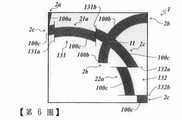
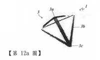
此外,該等條帶其中一條或多條,及/或該等第一微結構其中一個或多個,可以在一個或多個交叉區內交叉,其中該等條帶其中一條或多可以分別一次或兩次或多次交叉,及/或該等條帶其中一條或多條可以成對地,以不同的頻率交叉。如此,從三條條帶B1、B2、B3中分別選出的各條帶對B1和B2、B2和B3以及B1和B3,可以分別以以不同的頻率交叉。In addition, one or more of the strips, and/or one or more of the first microstructures, may intersect in one or more intersection regions, wherein one or more of the strips can be respectively once Or two or more crossings, and/or one or more of these strips can be crossed in pairs at different frequencies. In this way, the strip pairs B1 and B2, B2 and B3, and B1 and B3 respectively selected from the three strips B1, B2, and B3 can be crossed at different frequencies, respectively.
例如,三條封閉及/或開放的條帶B1、B2、B3交叉的方式可以是,條帶B1和B2交叉兩次,條帶B1和B3交叉四次,條帶B2和B3僅交叉一次。For example, three closed and/or open strips B1, B2, B3 can be crossed in a manner that strips B1 and B2 cross twice, strips B1 and B3 cross four times, and strips B2 and B3 cross only once.
也可以是一條條帶自己交叉,較佳地條帶不要自己交叉。It is also possible that the strips cross by themselves, preferably the strips do not cross by themselves.
其中,可以設計在所述交叉區其中一個或多個內,分別只有設置在各該交叉區內交叉的該條帶的該第一微結構或該等第一微結構。然後,在這個交叉區內,不設置其它交叉的條帶的該第一微結構或該等第一微結構。Wherein, it can be designed in one or more of the intersection areas, and respectively only the first microstructures or the first microstructures of the strips intersecting in the intersection areas are arranged. Then, in this intersecting area, the first microstructures or the first microstructures of other intersecting strips are not arranged.
不過,此外,也可以分別將在該交叉區內交叉的條帶其中兩個或多個的複數個第一微結構,設置在所述交叉區其中一個或多個內。其中較佳地,將所述交叉的條帶的該第一微結構或該等第一微結構設置於一個一維或二維光柵(raster)內,光柵的寬度尤其介於10~300μm之間。However, in addition, a plurality of first microstructures of two or more of the strips intersecting in the intersecting area may be respectively arranged in one or more of the intersecting areas. Preferably, the first microstructures or the first microstructures of the intersecting strips are arranged in a one-dimensional or two-dimensional raster, and the width of the grating is particularly between 10 and 300 μm .
以下將不同第一微結構的這個光柵稱為馬賽克面。Hereinafter, this grating with a different first microstructure is called a mosaic surface.
藉由這樣的馬賽克面,可以分別避免各該條帶的移動效果,尤其是光學移動效果的中斷,或至少讓這類中斷在光學上比較不容易看出,尤其是相對於條帶不具有馬賽克面的防偽元件,這類具有馬賽克面的條帶避免中斷或使中斷較不明顯的效果。With such a mosaic surface, the movement effect of each strip can be avoided, especially the interruption of the optical movement effect, or at least this type of interruption is not easy to see optically, especially relative to the strip without mosaic Surface anti-counterfeiting elements, such strips with mosaic surfaces have the effect of avoiding or making the interruption less obvious.
有利的是,可以在所述馬賽克面內,讓每一條穿過交叉區的條帶及/或每一第一微結構,分配到一個相同的交叉區面積比重,使得在交叉區內提供的每一條條帶都具有相同的比重,尤其是面積比重。Advantageously, in the mosaic surface, each strip passing through the intersection and/or each first microstructure can be allocated to the same proportion of the intersection area, so that every strip provided in the intersection area A strip has the same specific gravity, especially the area specific gravity.
假如兩條條帶及/或兩個第一微結構交叉,最好是分配一個面積,尤其是的一個交叉區面積的50%面積比重給所述交叉區內兩條條帶及/或兩個第一微結構中每一條/個。這樣一來,三條交叉的條帶及/或三個交交的第一微結構,這裡三個一般用n個表示,這三個中每一個都分配到交叉區的各三分之一面積比重,一般用1/n的面積比重表示。If two strips and/or two first microstructures intersect, it is best to allocate an area, especially 50% of the area of an intersecting area, to two strips and/or two intersecting areas. Each of the first microstructures. In this way, three intersecting strips and/or three intersecting first microstructures, where three are generally represented by n, each of these three is assigned to each one-third of the area of the intersection. Generally expressed by the area proportion of 1/n.
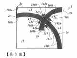
此外,也可以在所述交叉區其中一個或多個的區域內的所述條帶其中一條或多條之外,設置一個或多個平面區,這些平面區包含所述在各交叉區內交叉的該等第一微結構其中一個。所述一個或多個平面區,在此與各該交叉區的距離較佳地少於150μm,更佳地少於50μm。這個距離係由該交叉區及/或在該交叉區內交叉的該等條帶的最相近的外緣之間的距離,以及各該平面區的最相近的外緣之間的距離所決定。In addition, one or more plane areas may also be provided outside of one or more of the strips in one or more areas of the intersection area, and these plane areas include the intersections in each intersection area. One of these first microstructures. The distance between the one or more plane areas and each of the intersection areas is preferably less than 150 μm, more preferably less than 50 μm. This distance is determined by the distance between the closest outer edges of the intersection area and/or the strips that intersect in the intersection area, and the distance between the closest outer edges of each planar area.
藉由這樣的設計,可以有效加大分配給交叉區內交叉之該等條帶的該等第一微結構的既有面積,同時不會對光學外表造成負面影響。這樣一來,即可避免在移動、變形及/或翻轉效果過程中中斷,或至少讓這類中斷在光學上比較不容易看出來。所述移動、變形及/或翻轉效果,係由各該交叉區內交叉的條帶所提供的。With such a design, the existing area of the first microstructures allocated to the strips crossing in the intersection area can be effectively enlarged without negatively affecting the optical appearance. In this way, interruptions during movement, deformation, and/or flipping effects can be avoided, or at least such interruptions can be made optically less visible. The moving, deforming and/or flipping effect is provided by the strips that cross each other in the intersection area.
更佳地,所述條帶其中至少一條及/或所述第一微結構其中至少一個,可以中斷至少一次。More preferably, at least one of the strips and/or at least one of the first microstructures may be interrupted at least once.
在此,最好不要在中斷區內設置各該等條帶的該第一微結構或該等第一微結構,或不要讓所述第一微結構在這中斷區內延續。Here, it is better not to arrange the first microstructures or the first microstructures of the strips in the interrupted area, or do not allow the first microstructures to continue in the interrupted area.
這類中斷的功效是,改善由該等第一微結構提供的效果與該防偽元件的其它光學效果的重疊情況,進而提高該防偽元件的防偽效果。The effect of this type of interruption is to improve the overlap between the effects provided by the first microstructures and other optical effects of the anti-counterfeiting element, thereby improving the anti-counterfeiting effect of the anti-counterfeiting element.
所述各該條帶沿著其縱向所產生的中斷,其尺寸較佳地是在肉眼解析能力以下,這些中斷最好在往這個方向側邊延伸0.5~200μm,更佳地延伸1~100μm。The size of the interruptions generated along the longitudinal direction of each of the strips is preferably below the resolution of the naked eye. These interruptions preferably extend from 0.5 to 200 μm sideways in this direction, and more preferably extend from 1 to 100 μm.
較佳地,在兩條或多條條帶及/或兩個或多個第一微結構的至少一交叉區內,有至少一條條帶及/或至少一第一微結構中斷至少一次。Preferably, in at least one intersection of two or more strips and/or two or more first microstructures, at least one strip and/or at least one first microstructure is interrupted at least once.
更佳地,在兩條或多條條帶及/或兩個或多個第一微結構的一交叉區之外,有至少一條條帶及/或至少一第一微結構中斷至少一次。More preferably, outside of an intersection of two or more strips and/or two or more first microstructures, at least one strip and/or at least one first microstructure is interrupted at least once.
較佳地,隨機式及/或假隨機分散設置所述中斷,尤其是可以分別隨機及/或假隨機,將所述中斷其中一個或多個分散設置,使其平行及/或垂直於各該條帶的一個或多個切線向量。Preferably, the interrupts are arranged randomly and/or pseudo-randomly. In particular, one or more of the interrupts can be arranged randomly and/or pseudo-randomly respectively so as to be parallel and/or perpendicular to each of the interrupts. One or more tangent vectors of the strip.
此外,至少一條帶及/或至少一第一微結構,至少有一次錯位。當至少一條帶及/或至少一第一微結構的兩個部分及/或子區及/或區段,彼此錯開時,尤其是彼此偏移時,就會形成錯位。其中錯位程度的大小,尤其是偏移的大小,則可以是任意的大小。In addition, at least one strip and/or at least one first microstructure has at least one misalignment. When two parts and/or sub-regions and/or sections of at least one band and/or at least one first microstructure are staggered from each other, especially when they are offset from each other, a dislocation will be formed. The size of the degree of misalignment, especially the size of the offset, can be any size.
錯位的側邊尺寸其中一個或多個,尤其可以分別小於各該條帶的寬度。One or more of the side dimensions of the misalignment may be smaller than the width of each strip.
至少一條帶及/或至少一第一微結構,最好是至少有一次錯位,所述至少一次錯位尤其是可以隨機及/或假隨機分佈到所述至少一條條帶及/或至少一第一微結構的所述弧形長度上,較佳地分佈到所述弧形長度的一部份。更佳地,該等錯位,尤其是錯位程度及/或偏移程度的大小,可以隨機及/或假隨機分佈。尤其可以將該等錯位其中一個或多個,分別以隨機及/或假隨機分佈,使其平行及/或垂直於各該條帶的一個或多個切線向量。At least one strip and/or at least one first microstructure, preferably at least one dislocation, and the at least one dislocation can especially be randomly and/or pseudo-randomly distributed to the at least one strip and/or at least one first microstructure The arc length of the microstructure is preferably distributed to a part of the arc length. More preferably, the dislocations, especially the degree of dislocation and/or the magnitude of the degree of displacement, may be randomly and/or pseudo-randomly distributed. In particular, one or more of these dislocations can be randomly and/or pseudo-randomly distributed, respectively, so that they are parallel and/or perpendicular to one or more tangent vectors of each strip.
可以透過穿過至少一條條帶及或一第一微結構交叉一次,尤其是直線交叉一次,以及透過接著使該至少一條這樣被交叉的條帶及/或第一微結構相對於所述條帶及/或第一結構產生偏移,提供這樣的錯位。This can be achieved by passing through at least one strip and or a first microstructure to cross once, especially a straight line, and by then making the at least one such crossed strip and/or the first microstructure relative to the strip And/or the first structure is offset to provide such a misalignment.
更佳地,可以將該至少一交叉的角度,尤其是該至少一交叉角,任意定向,尤其是任意相對該至少一被交叉的條帶及/或第一微結構的定向及/或縱向延伸方向定向,俾使所述至少一被至少一交叉所交叉的條帶及/或第一微結構,以及所述至少一條帶及/或第一微結構轉入彼此後不會形成彼此齊平的狀態。More preferably, the at least one crossing angle, especially the at least one crossing angle, can be arbitrarily oriented, especially arbitrarily relative to the orientation and/or longitudinal extension of the at least one crossed strip and/or the first microstructure Orientation so that the at least one strip and/or the first microstructure crossed by at least one cross, and the at least one strip and/or the first microstructure will not be flush with each other after being transferred into each other state.
此外,可以使至少一被交叉的條帶及/或一第一微結構的交叉的相鄰部分,尤其是垂直於該至少一條帶及/或第一微結構的定向及/或縱向延伸方向,形成彼此偏移。In addition, at least one crossed strip and/or a first microstructure can be crossedAdjacent parts of, especially perpendicular to the orientation and/or longitudinal extension direction of the at least one strip and/or the first microstructure, are offset from each other.
錯位最好是能減少不希望的有色繞射情況,以便尤其可以提供改善的無色外表,進而提供改善的像元順序。The misalignment is preferably to reduce undesirable colored diffraction conditions, so that in particular, an improved colorless appearance can be provided, and thus an improved pixel order can be provided.
特別較佳地,可以透過在不同位置上,尤其是該條帶及/或第一微結構上的位置上,形成兩個同向的交叉,尤其是形成兩個彼此任意定向的交叉,更佳地透過兩個彼此平行的交叉,及透過將所述條帶及/或第一微結構以這樣方式切出來的子區偏移及/或錯開,使一條帶及/或一第一微結構的一個子區及/或一個區段相對於該沒有被交叉的條帶及/或第一微結構形成錯位,進而尤其產生條帶及/或第一微結構的子區及/或區段的錯位。Particularly preferably, it is possible to form two crosses in the same direction at different positions, especially the positions on the strip and/or the first microstructure, especially to form two crosses arbitrarily oriented with each other, more preferably Ground through two parallel crossings, and by offsetting and/or staggering the sub-regions cut out of the strips and/or first microstructures in this way, so that one strip and/or a first microstructure A sub-region and/or a section is misaligned with respect to the strip and/or the first microstructure that is not crossed, thereby particularly causing a misalignment of the sub-region and/or section of the strip and/or the first microstructure .
更佳地,至少所述錯位,尤其是所述錯位及/或偏移的大小,可以小於一條條帶及/或一第一微結構的寬度。此外,錯位,尤其是所述錯位及/或偏移的大小,可以對應於一條條帶的寬度。更佳地,至少所述錯位,尤其是所述錯位及/或偏移的大小,沒有大於一條條帶及/或一第一微結構的寬度的五倍,如此一來,尤其可以避免在產生該等第一微結構的移動、變形及/或翻轉效果時,較佳地係指在一個或多個像點產生移動、變形及/或翻轉效果時,發生跳動的情形。尤其較佳地,錯位,尤其是所述錯位及/或偏移的大小,平均是一條或多條條帶及/或第一微結構的寬度的1~50%,較佳地2~20%。More preferably, at least the dislocation, especially the size of the dislocation and/or offset, may be smaller than the width of a strip and/or a first microstructure. In addition, the dislocation, especially the magnitude of the dislocation and/or the offset, may correspond to the width of a strip. More preferably, at least the dislocation, especially the size of the dislocation and/or the offset, is not more than five times the width of a strip and/or a first microstructure. In this way, it is particularly possible to avoid The movement, deformation and/or reversal effect of the first microstructures preferably refers to a situation where one or more image points produce a movement, deformation and/or reversal effect. Particularly preferably, the dislocation, especially the magnitude of the dislocation and/or the offset, is on average 1-50%, preferably 2-20%, of the width of one or more strips and/or the first microstructure .
一個較佳的條帶及/或第一微結構產生方法的第一步驟,係提供一個檔案,這個檔案包含一個或多個像元的像點的一個或多個位置安排方式。在另一個步驟,最好由所述像點的位置安排方式,決定一條或多條至少有部分區段形成彎曲的條帶,及/或一條或多條條帶的一個或多個至少有部分區段形成彎曲的區段。此外,尤其在下一個步驟,在所述條帶其中一條/個或多條/個條帶或區段內,分別設置一個或多個第一微結構,所述第一微結構在曝光時會提供一個第一光學可變資訊,尤其是在將所述防偽元件翻轉及/或彎曲及/或旋轉時,所述第一微結構會提供一個或多個立體效果及/或移動效果,較佳地提供無色或單色的立體效果及/或移動效果。例如可以藉由電子束微影或雷射微影,將具有微結構的條帶製設於一主基體內。然後可以使用電鍍手段,將這樣的主基體的結構,複製到一個金屬基體內,尤其是由鎳組成的金屬基體。透過複製所述金屬基體,最好可以得到相對應的複製工具,例如可以藉由精密捲繞對位複製方法(roll-to-roll replication process)達到大量製造微結構的目的。The first step of a preferred method for generating strips and/or first microstructures is to provide a file containing one or more positional arrangements of the pixels of one or more pixels. In another step, it is best to determine one or more strips with at least partial sections forming a curve, and/or one or more strips with at least part The sections form curved sections. In addition, especially in the next step, one or more first microstructures are respectively arranged in one/or more/strips or sections of the strips, and the first microstructures areDuring exposure, a first optical variable information is provided, especially when the anti-counterfeiting element is flipped and/or bent and/or rotated, the first microstructure provides one or more three-dimensional effects and/or moving effects , Preferably provide a colorless or monochromatic three-dimensional effect and/or moving effect. For example, electron beam lithography or laser lithography can be used to fabricate strips with microstructures in a main substrate. Then, electroplating means can be used to copy the structure of such a main substrate into a metal substrate, especially a metal substrate composed of nickel. By replicating the metal matrix, it is best to obtain a corresponding replication tool. For example, a roll-to-roll replication process can be used to achieve mass production of microstructures.
最好可以在所述檔案內定義像元的順序,以便可以決定該等條帶及/或條帶段,俾使所述防偽元件翻轉及/或彎曲及/或旋轉時,藉由像點沿著所述條帶移動,產生所希望的像元順序。Preferably, the order of the pixels can be defined in the file, so that the strips and/or strip segments can be determined, so that when the anti-counterfeiting element is turned and/or bent and/or rotated, the image points are used along Moving along the strip produces the desired sequence of pixels.
最好可以在所述檔案內定義像元的順序,俾使所述防偽元件翻轉及/或彎曲及/或旋轉時,可以從一張無法辨識的圖像,例如一種隨機或假隨機設置的點設置方式及/或一種雲似的點分佈方式,藉由像點沿著所述條帶的移動,產生出一張可以辨識的圖像,例如面額。Preferably, the sequence of pixels can be defined in the file, so that when the anti-counterfeiting element is turned and/or bent and/or rotated, an unrecognizable image can be obtained, such as a random or pseudo-randomly set point The setting method and/or a cloud-like point distribution method generates a recognizable image, such as a denomination, by moving the image points along the strip.
較佳地,藉由一種複製方法,將所述第一及/或第二微結構形成於防偽元件的相同的一個層體,或兩個不同的層體內。該等層體最好是漆層,其厚度最好介於1~10μm之間。此外,該等層體也可以是防偽元件的一張支持膜,尤其是一張PET(聚對苯二甲酸乙二酯)膜。Preferably, by a replication method, the first and/or second microstructures are formed in the same layer or two different layers of the anti-counterfeiting element. The layers are preferably lacquer layers, and their thickness is preferably between 1 and 10 μm. In addition, the layers can also be a supporting film of the anti-counterfeiting element, especially a PET (polyethylene terephthalate) film.
由支持膜的可見面來看,位於複製層上方的一層或多層其它層體,可以是塗層,尤其是不透明、半透明或透明的塗層。較佳地,以花紋形態塗覆或形成這些塗層。所述複製層也可以是半透明或透明塗層。From the visible side of the support film, one or more other layers located above the replication layer may be coatings, especially opaque, translucent or transparent coatings. Preferably, these coatings are applied or formed in the form of a pattern. The replication layer can also be a translucent or transparent coating.
所述防偽元件的支持膜上,也可以設置一層或多層其它層體,尤其從下列層體種類選出所述其它層體的一層或多層:剝離層、保護層、附著層、防附著層、障礙層、黏著劑層。On the supporting film of the anti-counterfeiting element, one or more other layers can also be arranged, especially one or more of the other layers are selected from the following types of layers: peeling layer, protective layer, attachmentCoating layer, anti-adhesion layer, barrier layer, adhesive layer.
其內設有該等第一及/或第二微結構的所述防偽元件的一層或多層層體,更佳地,係塗上一層或多個反射層,這些層體分別覆蓋住所述一個或多個第一及/或第二微結構的至少部分區域。這些反射層最好是金屬反射層,尤其是由鋁(Al)、銅(Cu)或銀(Ag)組成的金屬層,及/或具有高折射能力的層體,所謂的高折射指數(high refraction index,HRI)層,例如二氧化鈦(TiO2)或硫化鋅(ZnS)。One or more layers of the anti-counterfeiting elements with the first and/or second microstructures are arranged therein, and more preferably, one or more reflective layers are coated, and these layers respectively cover the one or At least a partial area of the plurality of first and/or second microstructures. These reflective layers are preferably metal reflective layers, especially metal layers composed of aluminum (Al), copper (Cu) or silver (Ag), and/or layers with high refractive power, the so-called high refractive index (high Refraction index (HRI) layer, such as titanium dioxide (TiO2 ) or zinc sulfide (ZnS).
其內形成有該等第一及/或第二浮雕結構的所述防偽元件的一層或多層層體,還可以進一步印上一層或多個塗層,尤其是半透明或透明塗層。較佳地,以花紋形態塗覆或形成這些塗層,這些塗層最好具有不同的顏色。其內形成有該等第一及/或第二微結構的該層或該等層體,可以分別印上一個或多個顏色及/或複數個依觀看角度而變化的層體,例如塗上膽固醇狀液晶層及/或含有換色色素的層體。所述產生換色效果的層體,尤其可以由一個干涉層系統組成,這個干涉層系統例如可以是一個三層系統,由一層半透明吸收層、一層電介距離層和一層半透明或不透明的鏡層組成。One or more layers of the anti-counterfeiting elements with the first and/or second embossed structures formed therein may be further printed with one or more coatings, especially semi-transparent or transparent coatings. Preferably, these coatings are applied or formed in the form of patterns, and these coatings preferably have different colors. The layer or layers in which the first and/or second microstructures are formed can be printed with one or more colors and/or multiple layers that vary depending on the viewing angle, for example, coated A cholesteric liquid crystal layer and/or a layer containing a color-changing dye. The layer body that produces the color-changing effect can especially be composed of an interference layer system. This interference layer system can be, for example, a three-layer system consisting of a translucent absorption layer, a dielectric distance layer, and a translucent or opaque layer. Mirror layer composition.
上述的塗層,可以任意的形式組合,例如可以將上述層體中多層上下連續施覆於一層設有所述第一及/或第二浮雕結構其中一個或多個的層體的一側或兩側,這些層體尤其也可以分別形成花紋形狀。如此可以進一步達到光學效果,尤其是顏色效果,這些效果進一步提高防偽元件的防偽效果。The above-mentioned coatings can be combined in any form. For example, multiple layers of the above-mentioned layer can be continuously applied up and down on one side of a layer provided with one or more of the first and/or second relief structures or On both sides, these layers in particular can also be respectively formed in a pattern shape. In this way, optical effects, especially color effects can be further achieved, and these effects further improve the anti-counterfeiting effect of the anti-counterfeiting element.
1:防偽元件1: Anti-counterfeiting components
2:條帶、彎曲條帶2: Strips, curved strips
2a~2e:條帶、彎曲條帶、圓形條帶2a~2e: strips, curved strips, round strips
20a:條帶內輪廓、內輪廓、邊緣、一側20a: Strip inner contour, inner contour, edge, one side
20b:條帶外輪廓、外輪廓、邊緣20b: Strip outer contour, outer contour, edge
21a、22a:子區、條帶的子區21a, 22a: sub-regions, sub-regions of strips
3、3’:像元3. 3’: pixel
3a~3e:像點3a~3e: image point
300a~300f:連接線300a~300f: connecting line
30、31、32、33:位置30, 31, 32, 33: location
30:中心點30: Center point
4a~4e:條帶中心點、中心點4a~4e: strip center point, center point
5:防偽元件5: Anti-counterfeiting components
51:文件體51: file body
52:裝飾層52: decorative layer
53:黏著層、助黏層、黏著劑層53: Adhesive layer, adhesion-promoting layer, adhesive layer
54:保護層54: protective layer
Ra、Rb、Rc、Rd、Re:半徑R a, R b, R c , R d, R e: Radius
Ra:外半徑Ra : outer radius
B:寬度B: width
Λ:光柵週期Λ: grating period
R1、R2:方向R1, R2: direction
M:中心、中心點M: center, center point
α:方位角、方向角α: azimuth angle, direction angle
10:第一微結構10: The first microstructure
20:子塊、微結構、第二微結構20: Sub-block, microstructure, second microstructure
100:第一微結構元件100: The first microstructure element
10a:光柵、正弦光柵10a: grating, sine grating
10d:閃耀光柵10d: Blaze grating
10e:異方性平光結構、平光結構、往異方、以平光散射的結構10e: Heterotropic flat light structure, flat light structure, structure to different side, flat light scattering structure
100a、100b、100c:第一微結構、第一微結構元件、光柵結構100a, 100b, 100c: first microstructure, first microstructure element, grating structure
100b:微結構100b: Microstructure
11、12:交叉區11, 12: Intersection area
12:中斷12: Interrupt
121、122、123:中斷121, 122, 123: Interrupt
124:交叉區、中斷124: Intersection zone, interruption
13、131、132:錯位13, 131, 132: Dislocation
131a、131b:交叉邊131a, 131b: cross edge
132a、132b:交叉邊132a, 132b: cross edge
14:馬賽克面、馬賽克平面14: Mosaic surface, mosaic plane
141、142、143、144:子馬賽克面、子馬賽克平面141, 142, 143, 144: sub-mosaic plane, sub-mosaic plane
141a、142a、143a、144a:子馬賽克面、子馬賽克平面141a, 142a, 143a, 144a: sub-mosaic plane, sub-mosaic plane
15:空出的平面區、平面區15: Vacant plane area, plane area
200a、200b:第二微結構、第二微結構元件200a, 200b: second microstructure, second microstructure element
2f、2g、2h、2i、2j:條帶、圓條帶、圓形條帶2f, 2g, 2h, 2i, 2j: strips, round strips, round strips
3II、3III、3IV、3V、3VI:像元3II , 3III , 3IV , 3V , 3VI : pixel
3f、3g、3h、3i、3j:點、像點3f, 3g, 3h, 3i, 3j: point, image point
4f、4g、4h、4i、4j:中心、中心點4f, 4g, 4h, 4i, 4j: center, center point
Rf、Rg、Rh、Ri、Rj:半徑Rf, Rg, Rh, Ri, Rj: radius
Ri:內半徑Ri: inner radius
2k、2l、2m、2n、2o、2p:條帶、圓條帶、圓形條帶2k, 2l, 2m, 2n, 2o, 2p: strip, round strip, round strip
3VII:像元3VII : pixel
3VIII:像元3VIII : pixel
3k、3l、3m、3n、3o、3p:像點3k, 3l, 3m, 3n, 3o, 3p: image point
4k:中心、中心點4k: center, center point
Rk、Rl、Rm、Rn、Ro、Rp:半徑Rk, Rl, Rm, Rn, Ro, Rp: radius
2q、2r、2s、2t、2u:條帶、圓條帶、圓形條帶、圓條帶區段、圓形條帶區段2q, 2r, 2s, 2t, 2u: strip, round strip, round strip, round strip section, round strip section
2q:最大圓條段區段2q: Largest round bar segment
3IX、3X、3XI、3XII:像元3IX , 3X , 3XI , 3XII : pixel
3q、3r、3s、3t、3u:像點3q, 3r, 3s, 3t, 3u: image point
4q:中心、中心點4q: center, center point
Rq、Rr、Rs、Rt、Ru:半徑Rq, Rr, Rs, Rt, Ru: radius
R:半徑、半徑向量R: radius, radius vector
S:垂線S: perpendicular
T:切線向量T: Tangent vector
以下利用隨附之圖式,以多個實施例說明本發明。The following uses the accompanying drawings to illustrate the present invention with multiple embodiments.
〔第1a~1e圖〕係一具有多條條帶的防偽元件示意圖。[Figure 1a~1e] is a schematic diagram of an anti-counterfeiting element with multiple strips.
〔第2a圖〕係一防偽元件示意圖。[Figure 2a] is a schematic diagram of an anti-counterfeiting element.
〔第2b~2d圖〕係浮雕及光柵示意圖。[
〔第3圖〕係一具有大量條帶的防偽元件示意圖。[Figure 3] is a schematic diagram of an anti-counterfeiting element with a large number of stripes.
〔第4圖〕係一具有一交叉區的防偽元件示意圖。[Figure 4] is a schematic diagram of an anti-counterfeiting element with a cross area.
〔第5圖〕係一具有一交叉區和複數個中斷的防偽元件示意圖。[Figure 5] is a schematic diagram of an anti-counterfeiting element with a cross area and a plurality of interruptions.
〔第6圖〕係一具有一交叉區和複數個錯位的防偽元件示意圖。[Figure 6] is a schematic diagram of an anti-counterfeiting element with a cross area and a plurality of dislocations.
〔第7圖〕係一具有一交叉區的防偽元件示意圖。[Figure 7] is a schematic diagram of an anti-counterfeiting element with a cross area.
〔第8圖〕係一具有一交叉區的防偽元件示意圖。[Figure 8] is a schematic diagram of an anti-counterfeiting element with a cross area.
〔第9a圖〕係一防偽元件的光學效果的示意圖。[Figure 9a] is a schematic diagram of the optical effect of an anti-counterfeiting element.
〔第9b圖〕係一防偽元件的光學效果的示意圖。[Figure 9b] is a schematic diagram of the optical effect of an anti-counterfeiting element.
〔第10a圖〕係一防偽元件的光學效果的示意圖。[Figure 10a] is a schematic diagram of the optical effect of an anti-counterfeiting element.
〔第10b圖〕係一防偽元件在使用兩個光源照明下所產生的光學效果的示意圖。[Figure 10b] is a schematic diagram of the optical effect produced by an anti-counterfeiting element illuminated by two light sources.
〔第11a~11c圖〕係一防偽元件的光學效果的示意圖。[Figures 11a-11c] is a schematic diagram of the optical effect of an anti-counterfeiting element.
〔第12a~12b圖〕係一防偽元件隨著像點距離變化而產生的光學效果的示意圖。[Figure 12a~12b] is a schematic diagram of the optical effect of an anti-counterfeiting element with the change of the image point distance.
〔第13a~13b圖〕係一具有複數第一及第二微結構的防偽元件示意圖。[Figures 13a-13b] is a schematic diagram of an anti-counterfeiting element with a plurality of first and second microstructures.
〔第14a圖〕係一具有多條條帶的防偽元件示意圖。[Figure 14a] is a schematic diagram of an anti-counterfeiting element with multiple strips.
〔第14b圖〕係一具有多條條帶的防偽元件示意圖。[Figure 14b] is a schematic diagram of an anti-counterfeiting element with multiple strips.
〔第14c圖〕係一具有多條條帶的防偽元件示意圖。[Figure 14c] is a schematic diagram of an anti-counterfeiting element with multiple strips.
〔第14d圖〕係一具有多條條帶的防偽元件示意圖。[Figure 14d] is a schematic diagram of an anti-counterfeiting element with multiple strips.
〔第14e圖〕係一具有多條條帶的防偽元件示意圖。[Figure 14e] is a schematic diagram of an anti-counterfeiting element with multiple strips.
〔第15圖〕係一防偽元件的光學效果的示意圖。[Figure 15] is a schematic diagram of the optical effect of an anti-counterfeiting element.
〔第16a圖〕係一具有多條條帶的防偽元件示意圖。[Figure 16a] is a schematic diagram of an anti-counterfeiting element with multiple strips.
〔第16b圖〕係一具有多條條帶的防偽元件示意圖。[Figure 16b] is a schematic diagram of an anti-counterfeiting element with multiple strips.
〔第16c圖〕係一具有多條條帶的防偽元件示意圖。[Figure 16c] is a schematic diagram of an anti-counterfeiting element with multiple strips.
〔第16d圖〕係一具有多條條帶的防偽元件示意圖。[Figure 16d] is a schematic diagram of an anti-counterfeiting element with multiple strips.
〔第17a圖〕係一具有多條條帶的防偽元件示意圖。[Figure 17a] is a schematic diagram of an anti-counterfeiting element with multiple strips.
〔第17b圖〕係一具有多條條帶的防偽元件示意圖。[Figure 17b] is a schematic diagram of an anti-counterfeiting element with multiple strips.
〔第17c圖〕係一具有多條條帶的防偽元件示意圖。[Figure 17c] is a schematic diagram of an anti-counterfeiting element with multiple strips.
〔第17d圖〕係一具有多條條帶的防偽元件示意圖。[Figure 17d] is a schematic diagram of an anti-counterfeiting element with multiple strips.
〔第17e圖〕係一具有多條條帶的防偽元件示意圖。[Figure 17e] is a schematic diagram of an anti-counterfeiting element with multiple strips.
為讓本發明之上述及其他目的、特徵及優點能更明顯易懂,下文特舉本發明之較佳實施例,並配合所附圖式,作詳細說明如下:In order to make the above and other objects, features and advantages of the present invention more comprehensible, the preferred embodiments of the present invention will be described in detail in conjunction with the accompanying drawings as follows:
第1a~1e圖係顯示一份具有一個防偽元件1的防偽文件5的結構圖。Figures 1a~1e show a structure diagram of an
第1a~1d圖係該防偽元件1的俯視圖,第1e圖為該防偽元件1的剖示圖,該防偽元件1係施覆於一文件體上,或施覆於一防偽文件5上。Figures 1a to 1d are top views of the
所述防偽文件5最好由一身分證明文件組成,例如護照、通行卡、簽證或出入卡。不過,也可以是另外一種防偽文件5,例如紙鈔、股票或信用卡或金融卡。The
所述防偽文件5具有一文件體51和一個或多個防偽元件,第1a~1e圖即顯示所述防偽元件1。The
可以將該等防偽元件施覆於所述防偽文件5的文件體51上,或嵌設於所述防偽文件5的文件體51內,尤其是全部或部分嵌設於其內。The anti-counterfeiting elements can be applied to the
所述防偽文件5的文件體51最好是多層結構,尤其包含一個由一紙基體及/或塑膠基體組成的支持基體。此外,該文件體51還可以包含一層或多層保護層、一層或多層裝飾層及/或一個或多個防偽特徵。此外,該文件體51還可以包含其它層體,例如一層或多層剝離層、附著層、防附著層、障礙層及/或黏著劑層。該文件體51在此最好也包含一電子電路,尤其是一無線射頻識別(radio frequency identification,RFID)晶片,在該晶片內儲存有資訊。The
該文件體51可以具有一窗區,此窗區可以形成為該文件體51的穿透部,及/或形成為該文件體51的透明區。所述防偽元件1可以與該窗區重疊,而可從該防偽文件5的兩側看到該防偽元件1。The
所述防偽元件1尤其是由轉印膜的轉移層、層壓膜及/或薄膜件組成,尤其是以防偽補丁(security patch)或防偽條或防偽線的形式形成。或該防偽元件可以直接設於物件表面內。所述防偽元件,尤其是光學防偽元件,在此較佳地係施覆於防偽文件的表面上,或至少有部分嵌設於該防偽文件內。所述防偽元件1在此可以整面覆蓋住該防偽文件5的表面,及/或遮蓋該防偽文件5的部分,例如形成為條狀或補丁狀,如第1e圖中所示的防偽元件1設計。The
在此,所述防偽元件1較佳地具有一保護層54、一裝飾層52及一黏著層或助黏層53如此一來,該防偽元件1例如係以轉印膜的轉移層形式所形成,所述轉移層包含一保護層54、一裝飾層52及一黏著劑層53,並如第1e圖所示施覆於該文件體51的前側。Here, the
所述防偽元件1的裝飾層52形成一個或多個防偽特徵,這些特徵較佳地也在光學上可被人類觀看者看出來。The
因此,該等裝飾層52例如具有下列層體其中一層或多層:Therefore, the
該裝飾層52具有一層或多層分別具有一個或多個第一及/或第二微結構的層體。The
所述一個或多個第一及或第二微結構,在此可以在各層體內,透過全像曝光轉化為一體積全像。不過,所述一個或多個第一及或第二微結構也可以作為浮雕結構形成於各該層體的表面內。因此,這些層體最好是由光聚合物組成的層體,在光聚合物內設有複數個區域,這些區域具有用於產生一個體積全像的不同折射率。這些層體也可以是漆層或塑膠膜,透過複製方法將該微結構的表面浮雕形成於漆層或塑膠膜內。The one or more first and or second microstructures can be converted into a volume hologram through holographic exposure in each layer. However, the one or more first and or second microstructures can also be formed in the surface of each layer as a relief structure. Therefore, these layer bodies are preferably layer bodies composed of photopolymers, and a plurality of regions are provided in the photopolymers, and these regions have different refractive indexes for generating a volume hologram. These layers can also be lacquer layer or plastic film, and the surface relief of the microstructure is formed in the lacquer layer or plastic film through a replication method.
所述微結構較佳地為繞射結構,例如矩形繞射光柵、正弦形光柵,或也可以是第零階的繞射結構。所述微結構也可以是同方性及/或異方性平光結構、三角形閃耀光柵及/或大致上在反射時起作用的結構,例如微透鏡、微角柱或微鏡。The microstructure is preferably a diffraction structure, such as a rectangular diffraction grating, a sinusoidal grating, or a zeroth order diffraction structure. The microstructures can also be homotropic and/or anisotropic flat light structures, triangular blazed gratings, and/or structures that act substantially during reflection, such as microlenses, microcorner posts, or micromirrors.
所述一個或多個微結構最好是設於一條或多條至少有部分區段形成彎曲的條帶內,第1a~1d圖內顯示其中多條條帶2a~2e。此外,也可以在一條條帶的一個或多個至少有部分區段形成彎曲的區段內,例如在第1a~1d圖內顯示之條帶的區段內,設置所述第一微結構其中一個或多個。此外,所述第一微結構其中一個或多個也可以分別沿著一條或多條至少有部分區段形成彎曲的條帶延伸,或沿著一條條帶的一個或多個至少有部分區段形成彎曲的區段延伸。The one or more microstructures are preferably arranged in one or more strips with at least partial sections forming a bend, and Figures 1a to 1d show
所述裝飾層52最好具有一層或多層金屬層,這些金屬層最好分別不是設於防偽元件的整面,而是只設於其中部分。其中,所述金屬層可以不透明、半透明或可透射的。其中,所述金屬層最好是由不同金屬組成,這些不同的金屬層的反射譜及/或透射譜明顯不一樣。所述金屬層例如由鋁、銅、鉻、金、銀或這些金屬的一種合金組成。The
其中,所述一層或多層金屬層最好是以花紋(pattern)形狀形成,最好是字母數字記號及/或圖形及/或複雜的物體描繪等形式形成。Wherein, the one or more metal layers are preferably formed in the shape of a pattern, preferably in the form of alphanumeric signs and/or graphics and/or complex object depictions.
所述裝飾層52進一步可以包含有一層或多層塗層,最好是透明或半透明塗層。所述塗層,較佳地為藉由印刷方法塗覆的塗層,這些塗層具有一種或多種塗料及/或色素,這些塗料及/或色素融入一黏結劑矩陣內。The
所述裝飾層52更佳地具有一層或多層干涉層,這些干涉層對入射光會挑選波長反射或折射。這些層體例如可以是由薄膜元件組成,所述薄膜元件根據層體的設置方式產生一個依觀看角度不同而變化的色移效果,該等層體的光學厚度為入射光的一半或四分之一波長。這些層體很典型地包含一層電介間距層,該電介間距層尤其是設於一半透明吸收層及一半透明或不透明鏡層或反射層,這些層體較佳地可以由一層包含複數薄膜色素的層體所組成。The
所述裝飾層52進一步最好可以具有一層或多層液晶層,所述液晶層一方面使入射光極化(polarize),也會依液晶定向的不同,讓某些波長的入射光反射及/或透射。The
第1a圖顯示該防偽元件1的局部,該防偽元件1包含所述彼此錯開的彎曲條帶2a、2b、2c、2d、2e。所述條帶具有半徑Ra、Rb、Rc、Rd、Re。所述條帶的中心點4a、4b、4c、4d、4e係設於該等條帶2a、2b、2c、2d、2e的幾何中心,並分別與圓形條帶2a、2b、2c、2d、2e上所有點保持半徑Ra、Rb、Rc、Rd、Re的距離,使該等條帶2a、2b、2c、2d、2e的曲率分別為1/Ra、1/Rb、1/Rc、1/Rd、1/Re。該等條帶所在的平面,或空間上擴張的平面,係由一個二維座標系統撐開的,透過基本向量x和y描述這個座標系統,所述基本向量x和y最好如第1a圖所示彼此垂直。Figure 1a shows a part of the
不過,尤其也可以選擇具有兩個以上維數的座標系統,及/或至少一彎曲的條帶上的座標系統。However, in particular, it is also possible to choose a coordinate system with more than two dimensions, and/or toOne less coordinate system on the curved strip.
如第1a~1d圖所示,所有條帶都具有相同的半徑。更佳地,條帶2a~2e的半徑也可以不一樣。此外,所述條帶2a~2e其中至少一條可以在彎曲走向上有變化。最好是當條帶不是圓形,而是例如橢圓形及/或螺旋形及/或圓弧形時,才設計讓條帶2a~2e在彎曲走向有變化。所述條帶2a~2e更佳地可以是不斷的及/或可區別的及/或可結合為一體的曲線,其中,所述條帶2a~2e可以不一定要是一維曲線,較佳地也可以是二維曲線,例如是一個球形表面的子區。As shown in Figures 1a~1d, all strips have the same radius. More preferably, the radii of the
特別較佳地,所述條帶可以形成為封閉的條帶及/或由一個封閉的條帶其中至少一個子區所形成。尤其所有條帶的至少50%,較佳地70%,特別較佳地90%,可以分別形成一個封閉條帶的至少五分之一,較佳地至少四分之一,特別較佳地三分之一,尤其較佳地二分之一。此外,尤其所有條帶的至少50%,較佳地70%,特別較佳地90%,可以分別形成至少一個四分之一圓,較佳地至少一個三分之一圓,特別較佳地至少一個半圓。在第1a~1d圖內所示的實施例中,該等圖示所顯示的條帶2a、2b、2c、2d、2e為用虛線表示的二維圓形彎曲曲線。特別是當條帶是圓條帶或圓形條帶時,彎曲條帶的曲率的跡象(leading sign)不會改變,是恆定的。此外,一條條帶的曲率較佳地介於0.02~2mm-1之間,較佳地介於0.01~1mm-1之間。尤其較佳地,可以讓至少一條條帶,尤其是至少一圓形條帶,到處具有同一個曲率。特別較佳地,可以讓所有條帶2a~2e,尤其是所有圓形及/或橢圓形的條帶,其彎曲走向都一樣,第1a~1d圖內所示。尤其較佳地,所述條帶2a~2e的彎曲走向可以彼此不一樣。Particularly preferably, the strip may be formed as a closed strip and/or formed by at least one sub-region of a closed strip. In particular, at least 50%, preferably 70%, particularly preferably 90% of all strips can form at least one fifth, preferably at least one quarter, particularly preferably three of a closed strip. One-half, particularly preferably one-half. In addition, especially at least 50%, preferably 70%, and particularly preferably 90% of all strips can respectively form at least one quarter circle, preferably at least one third circle, particularly preferably At least one semicircle. In the embodiments shown in Figures 1a to 1d, the
該等設於條帶2a~2e內的第一微結構,提供一個第一光學可變資訊。第1a~1d圖所示的實施例中的這個第一光學可變資訊,是一個移動效果。其中,這個第一光學可變資訊包含一個或多個分別由多個像點組成的像元。The first microstructures arranged in the
該等設於條帶2a~2e內的第一微結構,在第1a~1d圖所示的實施例中,係產生一個像元3,此像元3尤其是由像點3a、3b、3c、3d、3e的一個布置所形成。所述防偽元件1最好提供觀看者一個或多個像元3,其中至少一個像元3例如可以形成為圖案(motif)。The first microstructures located in the
所述像點3a、3b、3c、3d、3e分別由該等條帶2a、2b、2c、2d或2e的第一微結構所產生。在將防偽元件1翻轉及/或彎曲及/或旋轉時,所述像點3a、3b、3c、3d、3e在使用至少一光源,較佳地使用一個點狀光源照明的情況下,沿著分別所屬的條帶移動。The image points 3a, 3b, 3c, 3d, and 3e are respectively produced by the first microstructures of the
所述像元3的像點3a、3b、3c、3d、3e,可以形成點狀,尤其是圓盤形狀,如第1a~1d圖所示。不過,像點3a、3b、3c、3d、3e也可以有其它的形狀,例如橢圓形。The image points 3a, 3b, 3c, 3d, and 3e of the
當該等條帶2a、2b、2c、2d、2e由一光源照射時,第1a圖中的像元3是可以被觀看者感知到的,或可以看到的。其中,該等條帶的設計是,在每一條條帶只有一個像點可以被觀看者看到。透過將這樣可被看到的像點3a、3b、3c、3d、3e間距不變地設置在該等條帶上,這些像點3a、3b、3c、3d、3e會提供該像元3。When the
尤其當觀看者觀看時,如果將包含該等條帶的該防偽元件1相對於觀看者及/或照射源,翻轉及/或彎曲及/或旋轉及/或傾斜,所述像元3會移動。特別較佳地,所述像元3係根據該防偽元件1相對於觀看者的翻轉及/或彎曲及/或旋轉及/或傾斜方向,沿著該等條帶,往每條條帶的兩個可能移動方向各一個方向移動,尤其是移動自由度的方向。Especially when the viewer is watching, if the
更佳地,所述像元3係以第1a圖中所示的五個像點3a~3e的布置,沿著五條條帶2a、2b、2c、2d、2e移動,使得即使翻轉及/或彎曲及/或旋轉該防偽元件1,第1a圖中所示的五個像點3a~3e的布置也會維持不變,及/或不會改變相對於第1a~1d圖所示、由向量x和y撐開的座標系統的定向。More preferably, the
所謂防偽元件1的旋轉,在此是指防偽元件1繞著防偽元件1的平面法線旋轉,所述平面法線係以矩形狀位於由向量x和y撐開的平面上。所謂防偽元件1的翻轉,是指防偽元件1繞著一個軸翻轉,這個軸位於由向量x和y撐開的平面上。The so-called rotation of the
有利的是,在該防偽元件1旋轉及/或彎曲及/或翻轉期間,所述像元3尤其可以改變像元3相對於一個沿著及/或平行於第1a~1d圖所示座標系統的向量x及/或y的軸的定向,較佳地持續地改變,以提供一個由觀看者看來是持續或不持續的移動效果。更佳地,在該防偽元件1旋轉及/或彎曲及/或翻轉期間,所述像元3保持像元3相對於一個平行及/或沿著於第1a~1d圖所示座標系統的向量x及/或y的軸的定向不變。Advantageously, during the rotation and/or bending and/or turning of the
第1a~1d圖中,所述像元3相對該由向量x及y標示的座標系統的定向,在整個移動過程,尤其是在該等位置30、31、32、32每一個位置上都是不變的。In Figures 1a~1d, the orientation of the
第1a~1d圖以一個任意的順序,顯示所述像元3的一個移動效果,所述像元3包含所述五個像點3a、3b、3c、3d、3e,其中,位於第1a圖中的像點3c位置上的像元3中心點30移動到第1b圖中的位置31上,繼續移到第1c圖中的位置32上,最後移動到第1d圖中的位置33上。所述像元3的移動效方向,可以最好是任意選擇的,以便提供不同的移動效果。Figures 1a~1d show a movement effect of the
第2a圖顯示所述防偽元件1的局部,其包含一彎曲條帶2的一個子塊20,該彎曲條帶2具有寬度B和半徑R。所述彎曲條帶2尤其可以是第1a~1e圖中的條帶2a~2e其中之一。Figure 2a shows a part of the
此外,第2a圖顯示一像點3a,其中該像點3a較佳地位於該條帶上,及最好可以沿著該條帶移動,這樣從觀看者來看會產生一個移動效果,尤其是一個持續性的移動效果。此外,第2a圖中顯示一截面A→A’,此一截面尤其是徑向往一個封閉的,較佳地圓形及/或橢圓形條帶的中心點行進,其中該截面往徑向穿過該條帶。此外,藉由中彼此垂直的向量x和y在第2a圖中顯示一個二維座標系統,該二維座標系統撐開該條帶2所在或該條帶2嵌入的平面。In addition, Figure 2a shows an
所述條帶2的寬度較佳地介於2~300μm之間,尤其是介於5~150μm之間,更佳地介於10~100μm之間。The width of the
所述條帶的面積會隨著該條帶的弧形長度及該條帶的寬度而變化,該條帶的寬度可以是不變或沿著該條帶變化。該條帶的寬度最好是不要隨著該條帶的走向變化,尤其是不要隨著一個相對於具有基本向量x和y的座標系統的方位角走向。The area of the strip changes with the arc length of the strip and the width of the strip, and the width of the strip can be constant or change along the strip. The width of the strip should preferably not change with the direction of the strip, especially not with an azimuth angle relative to the coordinate system with the basic vectors x and y.
一個內輪廓20a對應該條帶2一內緣及/或一條帶的一子區的內緣,該內緣最好具有內半徑Ri。所述條帶2及/或一條帶的該子區的該外輪廓20b,係對應該條帶的一外緣,該外緣最好具有外半徑Ra。該條帶2最好具有內半徑Ri。該內輪廓係設於該條帶指向一個圓的中心點M方向的一邊,該中心點M係由該彎曲半徑向量決定。而該條帶的外輪廓20b係設於該條帶遠離彎曲半徑向量的一側20a。此外,有一垂線S被畫入該半徑向量R延長部分,該垂線S垂直立於一切線向量T上,該垂線S貼近在該條帶的外緣。該切線向量T的方向在本實施例中係垂直於半徑向量R。An
該彎曲半徑向量,尤其是一個局部該彎曲半徑向量,最好是與在由一條帶2撐開的平面以內的一個任意點及/或位置有關,其中,該彎曲半徑向量的數額與角度,可以隨著由一條帶2撐開的平面上的位置及/或方位角α而變化。The bending radius vector, especially a local bending radius vector, is preferably related to an arbitrary point and/or position within the plane stretched by a
該彎曲半徑向量,尤其也可以與至少一條帶2的一內輪廓或邊緣20a或一外輪廓或邊緣20b有關,其中,該彎曲半徑向量的數額與角度,可以隨著由一條帶2的內輪廓及/或外輪廓上的位置及/或該方位角α而變化。The bending radius vector, in particular, may also be related to an inner contour or
在該條帶2及/或一條帶的該子區的一個特定方向角α上的內輪廓曲率,最好是永遠比在這個方向角α下外輪廓的曲率大。在一外輪廓上一特定方向角α的一特定位置及/或一特定點與一內輪廓上一特定方向角α的該相同位置及/或該相同點之間的距離,較佳地對應於該條帶2的寬度,尤其是對應隨著該特定方向角α的該位置及/或該點而變化的該條帶2寬度。The curvature of the inner contour at a specific direction angle α of the
在一更佳的實施例中,該條帶2及/或該條帶的一子區的平面,可以由至少一第一微結構10占滿。尤其該第一微結構10也可以順著該條帶2及/或該條帶一子區的內輪廓及/或外輪廓延伸。In a more preferred embodiment, the plane of the
第2b~2d圖分別顯示至少一第一微結構10的一個實施例,所述至少一第一微結構10例如可以設於第2a圖中所示的條帶2上,及/或設於第2a圖中所示的一條帶的該子區內上。Figures 2b to 2d respectively show an embodiment of at least one
尤其第2b~2d圖顯示該等第一微結構沿著第2a圖中所示的截線A→A’的截面。In particular, Figures 2b to 2d show the first microstructures along the section line A→A' shown in Figure 2a.
第2b圖顯示一個設計成第一微結構10的光柵10a,其具有正弦形的輪廓。該光柵10a具有複數個連續的結構元件,這些結構元件最好是週期性地彼此相間隔。所述個別的結構元件,在此較佳地,其縱向延伸比橫向延伸大很多,因此所述結構元件最好是線形,尤其是形成為光柵線,這些光柵線的橫截面呈正弦形狀。這些光柵線的走向,在此界定出光柵10a的該等微結構元件的縱向定向。所述光柵線的橫截面也可以不是正弦形,而是矩形,因而有一個矩形輪廓。Figure 2b shows a grating 10a designed as a
第2c圖顯示該等第一微結構10設計成閃耀光柵10d,該第一微結構尤其也可以形成為鋸齒狀的光柵及/或三角形光柵。FIG. 2c shows that the
所述閃耀光柵10d同樣較佳地由微結構元件的一個順序組成,該等微結構元件各具有一個三角形橫截面。在此,該等微結構元件的兩個側面的傾斜度與由向量x和y撐開的平面有差異,而使該等微結構元件具有一個不對稱的輪廓。在此,該等微結構元件的縱向延伸進一步同樣比橫向延伸大,尤其大很多,而使該等微結構元件同樣形成線形的微結構元件,這些微結構元件的橫截面在此是三角形。該等微結構元件的縱向延伸的走向,在此界定出該等微結構元件的縱向。The blazed grating 10d is also preferably composed of a sequence of microstructure elements, each of the microstructure elements having a triangular cross section. Here, the inclination of the two side surfaces of the microstructure elements is different from the plane stretched by the vectors x and y, so that the microstructure elements have an asymmetric profile. Here, the longitudinal extension of the microstructure elements is further larger than the lateral extension, especially much larger, so that the microstructure elements also form linear microstructure elements, and the cross-sections of these microstructure elements are triangular here. The longitudinal direction of the microstructure elements defines the longitudinal direction of the microstructure elements.
該等第一微結構10,尤其是第2b~2c圖該等第一微結構10的週期或光柵週期Λ,介於0.2~50μm之間,較佳地介於0.3~20μm之間,更佳地介於2~20μm之間,特別較佳地介於3~10μm之間,及/或該光柵深度介於50~15,000nm之間,有利是介於50~5,000nm之間,較佳地介於100~3,000nm之間。The period or grating period Λ of the
第2d圖顯示一第一微結構10,該第一微結構10係形成為往異方、以平光散射的結構及/或異方性平光結構10e。這類平光結構的特徵是,它們顯出一種不對稱的散射行為,藉此產生一個光學可變效果。當沿著首選方向進行觀察時,和沿著一個與所述首選方向相交及/或呈垂直的方向進行觀看相比較的話,所述異方性平光結構10e,在此對入射光具有比較大的散射能力及/或比較大的散射角度。所述平光結構10e的該等微結構元件的中間距離,較佳地介於0.5~10μm之間,特別較佳地介於0.8~5μm之間。Fig. 2d shows a
特別較佳地,該等第一微結構10其中至少三個,較佳地至少五個光柵週期,及/或該等第一微結構10其中至少三個,較佳地至少五個中間間距,係設在該至少一條帶2內,尤其是分配設於該條帶2的整個寬度範圍,及/或分配設於該條帶該至少一子區內,尤其是分配設於該條帶的該子區的整個寬度範圍。Particularly preferably, at least three of the
特別較佳地,該至少一第一微結構10可以進一步也由一種複數微鏡布置所組成,這些微鏡根據各傾斜角度,相對於由向量x和y撐開的平面傾斜。Particularly preferably, the at least one
更佳地,該第一微結構的第一微結構元件其中一個或多個,分別具有至少一個第一或第二稜角平面,所述第一或第二稜角平面尤其形成一個微鏡。在另一個實施例,該第一微結構10可以形成為透鏡結構、光柵10a、平光結構10e或閃耀光柵10d,及具有一個包含一個或多個微鏡的組合。較佳地,其中,該光柵10a具有一個正弦形、矩形、鋸齒形及/或三角形輪廓。More preferably, one or more of the first microstructure elements of the first microstructure respectively have at least one first or second angular plane, and the first or second angular plane especially forms a micromirror. In another embodiment, the
第3圖顯示一個防偽元件1,其包含複數個彎曲、但沒有封閉的條帶2及/或條帶的字區,其中條帶及/或子區在交叉區11內交叉及/或重疊。FIG. 3 shows an
第4圖顯示一個防偽元件1的局部,其局部包含三個彎曲的條帶2a、2b、2c,該等條帶2a、2b、2c尤其在一個交叉區11內交叉。此外,第4圖顯示沿著各條帶2a、2b、2c設置的第一微結構100a、100b、100c。FIG. 4 shows a part of an
較佳地,該等第一微結構100a、100b、100c及/或該等第一微結構100a、100b、100c的至少一結構件參數,尤其是微結構元件的間距、浮雕深度、微結構元件的縱向定向、首選方向、微結構元件的中間間距及/或該等微鏡的傾斜角度,是沿著各該條帶持續及/或不間斷改變。Preferably, the
第4圖例如顯示縱向延伸的定向持續改變的情形,或沿著各條帶2a、2b、2c的該等光柵結構100a、100b、100c的該等微結構的縱向定向。該等光柵結構100a、100b、100c在各該等條帶2a、2b、2c的每個位置上的縱向延伸,均與各該等條帶2a、2b、2c的相對位置的切線方向呈平行。該等光柵結構在與該等條帶相交的這個防偽元件1局部內,其寬度最好是七個光柵週期這麼大。Fig. 4 shows, for example, a situation in which the orientation of the longitudinal extension continuously changes, or the longitudinal orientation of the microstructures of the
較佳地,所述一個或多個條帶2a、2b、2c的一個或多個第一微結構100a、100b、100c的定向及/或縱向延伸,可以順著該等條帶2a、2b、2c一個輪廓,尤其是該內輪廓,較佳地該外輪廓。更佳地,在所述一個或多個條帶的大部分點上的該等第一微結構的定向,較佳地係沿著該各整個條帶,與所述一個或多個條帶的一個彎曲半徑向量形成相同的角度。尤其所述一個或多個第一微結構100a、100b、100c的定向及/或縱向延伸,可以大部分是垂直的,尤其是垂直於該彎曲半徑向量。在大部分點上,較佳地可以在理想情況下,對條帶2a、2b、2c的所有點而言,尤其是在一條或多條條帶是橢圓形及/或圓形的情狀下,在至少50%的點上,特別較佳地在至少70%的點上,尤其較佳地在至少85%的點上的第一微結構100a、100b、100c的定向,尤其是首選方向,可以與該等對條帶2a、2b、2c的垂線同一方向,尤其是垂直於該等條帶2a、2b、2c的一個或多個切線向量。Preferably, the orientation and/or longitudinal extension of one or more
如第4圖所示,該等條帶2a、2b、2c最好可以在一個交叉區11內交叉。第4圖中所示的交叉區11在幾何上對應於該等彎曲條帶2b與2c產生重疊及/或交叉的該平面上,其中,第4圖中的實施例中,條帶2b與2c的交叉區11內只有該條帶2c的該第一微結構100c,該條帶2b的該第一微結構100b沒有在交叉區11內。As shown in Fig. 4, the
第5圖顯示一防偽元件1,其包含三個彎曲的條帶2a、2b與2c,其具有第一微結構100a、100b或100c,該等條帶2b與2c尤其在一交叉區124內交叉。Figure 5 shows an
此外,該條帶2b具有複數個中斷122和124,在中斷122內沒有設置該第一微結構100b,在交叉區124內該微結構100b則出現一次中斷。此外,該條帶2c具有複數個中斷121和123,在中斷121和123內沒有設置該條帶2c的該等第一微結構100c。In addition, the
此外,尤其是所述中斷121、122、123及124其中之一可以在幾何上對應所述一個平面,這個平面上各該等條帶2a、2b及/或2c沒有具有第一微結構。可以隨機及假隨機分佈各該等條帶2a、2b或2c的中斷121、122、123及/或124。最好可以隨機及/或假隨機分佈中斷121~124,使其平行及/或垂直於一個相對應的切線向量。In addition, in particular, one of the
第5圖所示的實施例具有複數個中斷121、122、123,該等中斷121、122、123設於條帶2b和條帶2c的交叉區124以外。The embodiment shown in FIG. 5 has a plurality of
特別較佳地,該等設於交叉區124以外的中斷121、122及/或123,分別占該等條帶2a、2b及/或2c的面積及/或長度的0.1~30%,較佳地1~10%。這樣的中斷除了微結構的光學效果外,還產生一個散射效果,而使整個產生一個無色的印象。Particularly preferably, the
第6圖顯示該防偽元件1的一個實施例,該防偽元件1包含三個彎曲的條帶2a、2b與2c,其具有第一微結構100a、100b或100c,該條帶2c在兩個地方產生錯位131、132。該錯位131平行於交叉邊131a、131b,條帶的子區21a相對於第6圖的觀看方向往下移動該錯位131的長度這樣的距離。此外,該錯位132平行於交叉邊132a、132b,條帶的子區22a相對於第6圖的觀看方向往左邊移動該錯位132的長度這樣的距離。錯位131、132的移動方向,尤其彼此垂直。Figure 6 shows an embodiment of the
因為錯位131、132而偏移的子區21a、22a的面積,在跨越子區21a或22a走向及/或子區21a或22a的弧形長度的走向,會隨著寬度及/或寬度走向而改變。其中,所述子區21a或22a的寬度及/或寬度走向,是原始沒有交叉的條帶2c的寬度及/或寬度走向,所述子區21a或22a係從條帶2c中取的,或所述子區21a或22a係從條帶2c中移出的。The area of the
該等條帶2a、2b、2c及/或該等第一微結構100a、100b、100c的錯位131、132可以隨機及/或假隨機分佈,尤其是隨機及/或假隨機設置,及/或隨機及/或假隨機分佈及/或設置,使錯位131、132平行及/或垂直於一個對應的切線向量。The
更佳地,可以讓一個或多個錯位131、132所占的面積小於條帶2a、2b或2c及/或該等第一微結構100a、100b或100c的一個或多個寬度。較佳地,該等錯位錯開1~100μm,尤其是3~50μm的距離。和第5圖相似地,該等錯位也會產生一個額外的散射效果,而使該防偽元件整個產生一個無色的印象。More preferably, the area occupied by one or
第7圖顯示一防偽元件1,該防偽元件1包含三個彎曲的條帶2a、2b、2c,其具有第一微結構100a、100b、100c,該條帶2b、2c具有一馬賽克平面14。該馬賽克平面14細分為複數個子馬賽克平面141、142、143、144,這些子馬賽克平面141、142、143、144包含條帶2b、2c的第一微結構100b、100c。其中,至少一子馬賽克平面的第一微結構不同於該等子馬賽克平面剩下的第一微結構。FIG. 7 shows an
尤其在該等條帶2b、2c及/或該等條帶2b、2c的該等第一微結構100b、100c的馬賽克平面14內,有一個馬賽克形狀的布置,尤其是該等第一微結構100b、100c的一個光柵。這樣產生的效果是,觀看者看不出該二條帶有中斷。Especially in the
第8圖顯示一防偽元件1,該防偽元件1包含三個彎曲的條帶2a、2b、2c,其具有第一微結構100a、100b、100c,該條帶2b、2c在一交叉區11內具有一馬賽克平面14。該馬賽克細分為複數個子馬賽克平面141、142、143、144,這些子馬賽克平面141、142、143、144包含條帶2b、2c的第一微結構100b、100c。其中,至少一子馬賽克平面的第一微結構不同於該等子馬賽克平面剩下的第一微結構。進一步如第8圖所示,在平面區15內,尤其是在馬賽克平面14附近有一個子馬賽克平面141a、142a、143a、144a的布置,這些子馬賽克平面141a、142a、143a、144a具有第一微結構100b、100c。Figure 8 shows an
其中,一子馬賽克平面141、142、143、144、141a、142a、143a、144a的至少一第一微結構100b或100c不同於剩下的子馬賽克平面的第一微結構。Among them, at least one
尤其該等平面區15以及進一步也較佳地該等子馬賽克平面141a、142a、143a、144a,與該馬賽克平面14的距離小於150μm,更佳地少於50μm。這些子馬賽克平面帶來的效果是,該等條帶2b~2c的持續性移動效果,對沒有戴上輔具的肉眼而言,看起來像是沒有中斷。In particular, the distance between the
第9a圖顯示一防偽元件1,該防偽元件1包含一像元3,其中該像元3係由數字「4」和數字「2」組成,從第9a圖的觀看方向來看,數字「4」是設於數字「2」上方。Figure 9a shows an
第9b圖顯示一防偽元件1,該防偽元件1包含一像元3’,其中該像元3’係由一個翻轉了180度的數字「4」和一個翻轉了180度的數字「2」組成,從第9b圖的觀看方向來看,那個翻轉了180度的數字「2」是設於那個翻轉了180度的數字「4」上方。Figure 9b shows an
第9a~9b圖所示的實施例,該像元3係沿著該等條帶及/或該等條帶的第一微結構及/或過渡區,透過一個移動效果轉化成該像元3’,該等條帶及/或該等條帶的第一微結構及/或過渡區的設置設計,使得該等條帶及/或該等第一微結構使像元3能轉化成該像元3’,尤其是使像元3能變形成該像元3’,最好是使像元3能翻轉成該像元3’。透過使該防偽元件1相對於一個光源及/或一個觀看者翻轉及/或彎曲及/或旋轉,能讓觀看者感知到第9a圖中的像元3轉變或轉化成第9b圖中的像元3’。In the embodiment shown in Figures 9a-9b, the
第10a圖顯示一防偽元件1的示意圖,該防偽元件1包含一像元3,其中該像元3設計成數字「5」。使防偽元件1翻轉及/或彎曲及/或旋轉時,該像元3三個作為例子的像點3a、3b、3c可以在該等彎曲條帶2a、2b、2c或條帶段上面往條帶2a、2b、2c兩個方向移動到位置30、31、32上。最好在防偽元件1翻轉及/或彎曲及/或旋轉時,觀看者會感知到一個持續的移動效果,其中該像元3尤其是可以持續在位置30、31、32之間往一個特定的方向R1沿著該等條帶2a、2b、2c移動,及在翻轉方向及/或彎曲方向及/或旋轉方向發生變化時,該像元3可以提供一個相對於該特定方向R1的移動,也就是往方向R2的移動,以及相反過來。Fig. 10a shows a schematic diagram of an
第10b圖顯示在照明下在防偽元件1上看到的光學效果顛倒情形,該防偽元件1具有兩個設計成數字「5」的像元3、3’,其中每個像元都透過各一個光源所提供。沿著由單一像點的順序所顯示的、由像元3、3’連接起來的圓條帶或圓形條帶,最好設置閃耀結構,尤其是線性閃耀光柵,在此例子該等閃耀光柵的光柵週期為6μm,而該等閃耀光柵的光柵深度為2μm。此實施例所述線性閃耀光柵的縱向延伸,在條帶的每個位置上,都是垂直於該等條帶的對應位置上的半徑向量。Figure 10b shows that the optical effect seen on the
當使第10b圖中所示的防偽元件翻轉及/或彎曲及/或旋轉時所產生的光學效果,在於設計成數字「5」的像元3、3’所產生的移動,觀看者可以透過像元在該防偽元件下面或上面的虛擬移動,得到一個立體印象。The optical effect produced when the anti-counterfeiting element shown in Figure 10b is turned over and/or bent and/or rotated is the movement produced by the
第11a~11c圖顯示一防偽元件1的示意圖,該防偽元件1包含四個像點3a、3b、3c、3d,這些像點3a、3b、3c、3d一起形成一個金字塔形像元3。所述四個點狀元件3a、3b、3c、3d分別位於所述彎曲的條帶2a、2b、2c、2d其中一條上面,及形成該由四個三角形平面組成的金字塔的四個角落,防偽元件1翻轉及/或彎曲及/或旋轉時,該等像點會提供一個移動效果,使像點3a、3b、3c、3d可以在其對應的條帶2a、2b、2c、2d上,各依照翻轉方向及/或彎曲方向及/或旋轉方向往前及/或往後移動。Figures 11a-11c show a schematic diagram of an
第11a~11c圖所示的彎曲條帶2a、2b、2c、2d,具有彼此不同的彎曲半徑,其中該條帶2a的曲率比條帶2b、2c、2d的曲率小。The
此外,第11a~11c圖顯示該四個像點3a、3b、3c、3d在其對應條帶2a、2b、2c、2d上移動歷程,分別係位於不同的位置30、31、32,其中該像點3a因為條帶2a的曲率相對於條帶2b、2c、2d的曲率比較小,而在條帶2a上經過的距離比像點3b、3c、3d還長,進而提供一個讓觀看者可以感知到的金字塔立體移動效果。In addition, Figures 11a-11c show the movement history of the four
在第11a~11c圖內所顯示的這樣一種立體效果,係經過將該像元3形成為一個立體金字塔的二維投影而產生的,其中,在移動期間,因為條帶2b、2c、2d的對應曲率很強,所述金字塔的三個像點3b、3c、3d的位置只會些微改變,而位於金字塔頂端的像點3a則走過有些彎曲的條帶2a上一段很長的距離。所以在移動效果過程中,從觀看者的來看,該金字塔會變形,而觀看者的大腦會將金字塔的這個變形詮釋為在立體空間內一個立體物體的變形。The three-dimensional effect shown in Figures 11a-11c is produced by forming the
藉由使防偽元件1相對於至少一光源及/或相對於該觀看者翻轉及/或彎曲及/或旋轉,可提供該等像點3a、3b、3c、3d的移動效果。By turning and/or bending and/or rotating the
第12a~12b圖顯示第1圖中所示的一防偽元件1的顛倒光學效果,該防偽元件1具有兩個由複數個設於該等條帶上的像點3a、3b所組成的像元3、3’,所述像元彼此比較下具有同樣的金字塔形狀。該等像元3的該等像點3a彼此相隔一個距離,而這些像點3a之間的距離可以被肉眼解析,使得第12a圖中的金字塔形狀像元3的各個像點都可以被感知到。相對地,該等像元3’的該等像點3b的密度很高,使得各個點之間的距離無法被肉眼解析,所以金字塔形狀像元3’可以被感知成稍微模糊或持續不斷的金字塔形布置。Figures 12a-12b show the inverted optical effect of an
第11a~11c圖、第12a~12b圖中所示的條帶中的圓條帶或圓形條帶,其半徑介於金字塔頂端像點3a的10mm與金字塔底部像點3c的1mm之間。The round strips or circular strips in the strips shown in Figures 11a to 11c and Figures 12a to 12b have a radius between 10 mm at the
第13a~13b圖顯示一防偽元件1作為例子,該防偽元件1係由一個或多個第二微結構產生一個第二光學資訊。Figures 13a-13b show an
第13a圖顯示一防偽元件1,該防偽元件1尤其設置第4圖所示具有該等第一微結構元件100a、100b和100c的條帶2a、2b和2c設置於一個具有一第二微結構20的平面區內。其中,該等第一微結構元件100a、100b及/或100c沒有和該等第二微結構20的該等第二微結構元件200a重疊。Fig. 13a shows an
第13b圖顯示第一微結構和第二微結構的一種布置,第一微結構和第二微結構中該等產生該第一光學可變效果的條帶其中一個或多個,在此是條帶2a、2b,截切該第二微結構20的平面區。Figure 13b shows an arrangement of the first microstructure and the second microstructure. In the first microstructure and the second microstructure, one or more of the strips that produce the first optically variable effect are shown here. The
第13b圖中的情況,最好讓該第二微結構20以及條帶2a、2b的平面區也可以轉化成碎片融入彼此(rasterzied)。為達此目的,該微結構20以及條帶2a、2b、2c往至少一個特定方向分別被割分成大量的條狀子區。這些條狀子區設置後的彼此關係是,一個包含該微結構20或該微結構20的一部份的條狀子區,係與兩個具有各一條狀子區的交叉邊相鄰,後者條狀子區包含條帶2a、2b、2c其中一條或多條,或條帶2a、2b、2c的一個或多個部分,以及相反。因此包含該等微結構的該等條狀子區,以及包含該等條帶的該等條狀子區,會往一個垂直於切向的方向,在空間上彼此穿插。其中,該條體的寬度較佳地少於300μm。In the situation in Fig. 13b, it is better that the
該等第二微結構20最好產生一個光學可變的資訊。The
該等第二微結構20最好分別包含複數個第二微結構元件200a、200b,最好透過第二微結構元件間距、浮雕深度、浮雕形狀及第二微結構元件的縱向定向等參數,來描述該等第二微結構元件200a、200b的特徵。The
在此,該等第二微結構元件200a及/或200b較佳地形成為線形結構元件,尤其具有三角形橫截面。所述該等線形結構元件如第13b圖所示布置,及提供一個看起來是一維的浮雕圖像,尤其是一個看起來是立體無色的浮雕圖像。Here, the
此外,該等第二微結構20也可以具有複數個第二稜角平面,在光反射及/或繞射時,該等第二稜角平面會提供一個隨著該等第二稜角平面走向及/或傾斜角走向而變化的浮雕圖像。In addition, the
不過,該等第二微結構分別也可以形成一個光柵,尤其是正弦形狀或矩形或三角形的光柵、一個異向散射結構、一個平光結構、一個閃耀光柵及/或一個表面全像圖。該等第一微結構和第二微結構也可以與一層金屬反射層及/或具高折射指數的反射層及/或一層產生色移效果的層體結合,之前對此已有說明。該等第一微結構和第二微結構也可以藉由全像曝光轉換成一個體積全像圖。However, the second microstructures can also form a grating, in particular a sinusoidal or rectangular or triangular grating, an anisotropic scattering structure, a flat light structure, a blazed grating, and/or a holographic surface image. The first and second microstructures can also be combined with a metal reflective layer and/or a reflective layer with a high refractive index and/or a layer that produces a color shift effect, which has been described before. The first microstructure and the second microstructure can also be converted into a volume holographic image by holographic exposure.
第14a~14e圖顯示一防偽文件的結構,該防偽文件具有一防偽元件。第14a~14d圖顯示一防偽元件1的俯視圖,第14e圖顯示不同觀看角度下的一防偽元件1的花紋照片。Figures 14a-14e show the structure of an anti-counterfeiting document, which has an anti-counterfeiting element. Figures 14a-14d show a top view of an
第14a圖中顯示如第1a圖所顯示的該相同像元,此像元由五個點或像點3f、3g、3h、3i、3j組成。不過與第1a圖不同的是,該等圓條帶或圓形條帶2f、2g、2h、2i、2j的中心或中心點4f、4g、4h、4i、4j係隨機或假隨機布置。該等中心或中心點4f、4g、4h、4i、4j的布置,也不是顯示由該五個點或像點3f、3g、3h、3i、3j組成的該像元,尤其是根據該五個點或像點3f、3g、3h、3i、3j的位置布置該等中心或中心點4f、4g、4h、4i、4j。條帶2f、2g、2h、2i、2j內的微結構選擇與布置,最好是能在一個特定的照明角度及/或觀看角度下,讓所希望的像元,尤其是包含像點3f、3g、3h、3i、3j的該像元能顯現給觀看者看到。在所有其它照明角度及/或觀看角度下,像點3f、3g、3h、3i、3j在條帶2f、2g、2h、2i、2j上分散開來,且該像元,尤其是包含像點3f、3g、3h、3i、3j的該像元無法再被感知。第14b~14d圖顯示此例中五個像點3f、3g、3h、3i、3j的散開示意圖。Figure 14a shows the same pixel as shown in Figure 1a. This pixel is composed of five points or
在可隨意選擇情況下,只存在條帶的區段。較佳地這些區段結束的位置是,在所述特定的照明角度及/或觀看角度下,該像元可以被看到或感知到的地方,這樣的設置尤其可以比較容易找到正確或適合的角度配合。同樣地也可以將隨機或假隨機不同的半徑,分配給該等圓條帶或圓形條帶。In the case of optional selection, there are only striped sections. Preferably, the end position of these segments is the place where the pixel can be seen or perceived under the specific illumination angle and/or viewing angle. This setting makes it easier to find the correct or suitable one. Angle fit. Similarly, random or pseudo-random different radii can be assigned to the round strips or round strips.
第14e圖之第(a)~(d)小圖顯示一個防偽元件1的一個有參考性的設計的照片,該防偽元件1係由圓條帶或圓形條帶所組成,這些圓條帶或圓形條帶具有假隨機設置的圓條帶或圓形條帶中心或中心點,其中,所述圓條帶或圓形條帶其中兩個圓條帶或圓形條帶,分別以元件符號2i或2j標示,尤其是如第14e圖之第(a)小圖所示,可以看到由像點組成字母「K」形狀的該像元3II。當防偽元件1向右傾斜時,該等像點會分散開來,被定義出的分配關係就消失了,該像元3II無法再被感知了,如第14e圖之第(b)~(d)小圖所示。尤其在防偽元件1向右傾斜時,所述可以被感知為字母「K」的像元3II會轉換為一個散開的像元3III。The small pictures (a)~(d) of Figure 14e show a photo of a reference design of an
第15圖顯示一防偽元件1的光學效果的兩張攝影影像,該防偽元件1包含兩個在照明下形成數字「5」和字母「K」的像元3IV和3V,這兩個像元3IV和3V最好已經透過一個唯一的光源所提供。其中,較佳地先計算出這兩個像元3IV和3V所需的圓條帶或圓形條帶,接著將這些的圓條帶或圓形條帶上下疊置。最好由一個計算軟體分配大約一樣多的圓條帶或圓形條帶交叉點給這兩個3IV和3V。如此一來,這兩個3IV和3V顯現出的亮度尤其大約會是類似的。該等微結構較佳地是不對稱的結構,尤其是閃耀類的結構,例如閃耀光柵或微鏡。現在這些微結構設置於所述兩個像元3IV和3V所述圓條帶或圓形條帶內及確定方向,使所述兩個像元3IV和3V較佳地不會在所述圓條帶或圓形條帶的相同位置上亮起來。最好是讓所述兩個像元3IV和3V剛好顯現在所述圓條帶或圓形條帶上的對面。該等微結構的設置,例如是讓所述兩個像元3IV和3V剛好尤其往所述同一個方向繞圈圈移動。在第15圖所示的防偽元件翻轉及/或旋轉時所產生的光學效果是,像元「5」和「K」在該圓條帶或圓形條帶上的位置最好互換。尤其,在此例子閃耀光柵6的光柵週期也是6μm,閃耀光柵6的光柵深度也是2μm。若是使用對稱的光柵,例如正弦形光柵,取代閃耀光柵,則兩個像元尤其會同時及因此尤其相重疊顯現在兩個位置上。透過在翻轉及/或旋轉時檢查所述兩個像元的位置調換或位置變換,最好是可以很簡單、間接地證明有閃耀類的微結構存在。Figure 15 shows two photographic images of the optical effect of an
如上所述,第15圖之第(a)小圖顯示該防偽元件1,該防偽元件1包含該等像元3IV和3V,其中像元3IV係設計成數字「5」並可被觀看者感知,像元3V係設計成字母「K」並可被觀看者感知。第15圖之第(b)小圖顯示在第15圖之第(a)小圖中所示該防偽元件1向右邊翻轉後,該防偽元件1包含該等像元3VI和3VII,其中像元3VI係設計成字母「K」並可被觀看者感知,像元3VII係設計成數字「5」並可被觀看者感知。最好是在該防偽元件1向右邊翻轉後,該像元3IV(數字「5」)在其位置上被該像元3VI(字母「K」)取代,在該防偽元件1向右邊翻轉後,該像元3V(字母「K」)在其位置上被該像元3VII(數字「5」)取代。As mentioned above, the small picture (a) of Fig. 15 shows the
第16a~16d圖顯示一防偽文件的結構,該防偽文件具有一防偽元件1,其中,該等中心或中心點4k,尤其是至少75%,較佳地至少90%,尤其較佳地所有的圓條帶或圓形條帶2k、2l、2m、2n、2o、2p的中心或中心點4k是一樣的,或近乎一樣的。所謂的近乎一樣,是指尤其是大部分,較佳地所有的圓條帶或圓形條帶2k、2l、2m、2n、2o、2p的中心或中心點4k,其彼此最大的距離尤其是不超過最大圓條帶或圓形條帶2k的半徑Rk的10%,較佳地不超過半徑Rk的5%,及/或所述中心或中心點4k,尤其是大部分,較佳地所有的圓條帶或圓形條帶2k、2l、2m、2n、2o、2p的中心或中心點4k,其彼此最大的距離尤其是不超過3mm,更佳地不超過1mm,尤其較佳地不超過0.5mm。尤其是從該像元3VIII被分配到像點3k、3l、3m、3n、3o、3p的各自位置得出各該圓條帶或圓形條帶2k、2l、2m、2n、2o或2p的半徑的Rk、Rl、Rm、Rn、Ro或Rp。該等條帶2k、2l、2m、2n、2o、2p內的微結構的最好選擇和布置,是在所希望的照明情況及觀看情況下,顯現出該像元3VIII。將所述防偽元件1翻轉或旋轉時,該像元3VIII較佳地繞著該等圓條帶或圓形條帶2k、2l、2m、2n、2o、2p的中心或中心點4k,沿著條帶2k、2l、2m、2n、2o、2p一起旋轉。例如該像元呈現出一隻鳥,在沿著圓形翻轉或旋轉時這隻鳥會飛。同樣地,也可以將圓條帶或圓形條帶相疊,以產生一個第二像元,使得該等微結構的設置與定向,尤其達到所述兩個像元不會在同一位置上亮起來的效果。例如可以讓第一像元呈現出一隻鴿子,第二像元呈現出一隻老鷹,在翻轉或旋轉時,老鷹最好是虛擬地從鴿子下方飛過。Figures 16a to 16d show the structure of an anti-counterfeiting document. The anti-counterfeiting document has an
如上述,一個防偽元件1的所有圓條帶或圓形條帶具有一樣或幾乎一樣的中心或中心點,這樣設計的好處,尤其是比較少圓條帶或圓形條帶相交,因而使該等像元最好顯得比較亮。As mentioned above, all round strips or circular strips of an
第17a~17e圖顯示一防偽文件的結構,該防偽文件具有一防偽元件1,其中,該等中心或中心點4q,至少75%,較佳地至少90%,尤其較佳地所有的圓條帶或圓形條帶2q、2r、2s、2t、2u的中心或中心點4q是一樣的,或近乎一樣的,或圓形條帶2q、2r、2s、2t、2u的條帶區段或區是一樣的,或近乎一樣的。所謂的近乎一樣,是指尤其是大部分,較佳地所有的圓條帶或圓形條帶2q、2r、2s、2t、2u的中心或中心點4q,或圓條帶區段或圓形條帶區段2q、2r、2s、2t、2u的中心或中心點4q,其彼此最大的距離尤其是不超過最大圓條帶或圓形條帶2q或最大原條帶區段2q的半徑Rq的10%,較佳地不超過半徑Rq的5%,及/或所述中心或中心點4q,尤其是大部分,較佳地所有的圓條帶或圓形條帶2q、2r、2s、2t、2u的中心或中心點4q,或圓形條帶2q、2r、2s、2t、2u的所有原條帶區段或區段的中心或中心點4q,其彼此最大的距離尤其是不超過3mm,更佳地不超過1mm,尤其較佳地不超過0.5mm。尤其是從該像元3IX被分配到像點3q、3r、3s、3t或3u的各自位置,得出各該圓條帶或圓形條帶2q、2r、2s、2t或2u的半徑的Rq、Rr、Rs、Rt或Ru,或得出各該圓條帶區段或圓形條帶區段2q、2r、2s、2t或2u的半徑的Rq、Rr、Rs、Rt或Ru。該等圓條帶或圓形條帶2q、2r、2s、2t或2u內的微結構,或該等圓條帶區段或圓形條帶區段2q、2r、2s、2t、2u內的微結構,其較佳的選擇和布置,在所希望的照明情況及觀看情況下,顯現出來該像元3IX。將所述防偽元件1翻轉及/或旋轉時,該像元3IX最好是透過消失及/或新顯現的及/或持續存在的像點3q、3r、3s、3t、3u而產生變化,使得觀看者可以感知到一幅動畫。例如該像元可以呈現出一隻鳥,在繞著圓圈翻轉或旋轉時這隻鳥會飛翔,及在此看起來在揮動翅膀。Figures 17a to 17e show the structure of an anti-counterfeiting document, which has an
第17b~17e圖係顯示一幅骰子點3q、3r、3s、3t、3u的動畫,其中,動畫是從五個骰子點3q、3r、3s、3t、3u「往下數到」兩個骰子點3q、3u,意思是說骰子點的數目尤其是以第17b~17圖的順序分別減少一個。Figures 17b~17e show an animation of
同樣地,也可以將條圓帶或圓形條帶相疊,以產生一個第二像元,使得該等微結構的設置與定向,尤其達到所述兩個像元不會在同一位置上亮起來的效果。例如可以讓第一像元顯示一隻飛翔鴿子的動畫,第二像元顯示一個沒有變化的像元,例如一個面額。一個動畫與一個靜止像元這樣的組合,很容易溝通,因而能提高防偽效果。Similarly, it is also possible to stack round strips or circular strips to produce a second pixel, so that the setting and orientation of the microstructures, especially to achieve that the two pixels will not be bright at the same position. Up the effect. For example, the first pixel can display an animation of a flying pigeon, and the second pixel can display an unchanged pixel, such as a denomination. The combination of an animation and a static pixel can be easily communicated, thus improving the anti-counterfeiting effect.
雖然本發明已利用上述較佳實施例揭示,然其並非用以限定本發明,任何熟習此技藝者在不脫離本發明之精神和範圍之內,相對上述實施例進行各種更動與修改仍屬本發明所保護之技術範疇,因此本發明之保護範圍當視後附之申請專利範圍所界定者為準。Although the present invention has been disclosed using the above-mentioned preferred embodiments, it is not intended to limit the present invention. Anyone who is familiar with the art without departing from the spirit and scope of the present invention may make various changes and modifications relative to the above-mentioned embodiments. The technical scope of the invention is protected. Therefore, the scope of protection of the invention shall be subject to the scope of the attached patent application.
1:防偽元件1: Anti-counterfeiting components
2a~2e:條帶、彎曲條帶、圓形條帶2a~2e: strips, curved strips, round strips
3:像元3: pixel
3a~3e:像點3a~3e: image point
4a~4e:條帶中心點、中心點4a~4e: strip center point, center point
Ra、Rb、Rc、Rd、Re:半徑R a, R b, R c , R d, R e: Radius
Ra:外半徑Ra : outer radius
Claims (49)
Translated fromChineseApplications Claiming Priority (3)
| Application Number | Priority Date | Filing Date | Title |
|---|---|---|---|
| ??102017106433.8 | 2017-03-24 | ||
| DE102017106433.8 | 2017-03-24 | ||
| DE102017106433.8ADE102017106433A1 (en) | 2017-03-24 | 2017-03-24 | Security element and method for producing a security element |
Publications (2)
| Publication Number | Publication Date |
|---|---|
| TW201902729A TW201902729A (en) | 2019-01-16 |
| TWI749196Btrue TWI749196B (en) | 2021-12-11 |
Family
ID=61763992
Family Applications (1)
| Application Number | Title | Priority Date | Filing Date |
|---|---|---|---|
| TW107110106ATWI749196B (en) | 2017-03-24 | 2018-03-23 | Anti-counterfeiting element and manufacturing method of anti-counterfeiting element |
Country Status (7)
| Country | Link |
|---|---|
| US (1) | US11345178B2 (en) |
| EP (1) | EP3600903B1 (en) |
| JP (2) | JP7102436B2 (en) |
| AR (1) | AR111388A1 (en) |
| DE (1) | DE102017106433A1 (en) |
| TW (1) | TWI749196B (en) |
| WO (1) | WO2018172528A2 (en) |
Families Citing this family (4)
| Publication number | Priority date | Publication date | Assignee | Title |
|---|---|---|---|---|
| GB2576218B (en)* | 2018-08-10 | 2021-09-15 | De La Rue Int Ltd | Security devices and methods of authentication thereof |
| CN111352128B (en)* | 2018-12-21 | 2023-03-24 | 上海微功智能科技有限公司 | Multi-sensor fusion sensing method and system based on fusion point cloud |
| US20220388326A1 (en)* | 2019-09-30 | 2022-12-08 | Zhongchao Special Security Technology Co., Ltd | Optical anti-counterfeiting element and anti-counterfeiting product |
| DE102023125661A1 (en)* | 2023-09-21 | 2025-03-27 | Giesecke+Devrient Currency Technology Gmbh | Optically variable security element with color-shifting interference layer element, valuable object and manufacturing process |
Citations (9)
| Publication number | Priority date | Publication date | Assignee | Title |
|---|---|---|---|---|
| CN1423598A (en)* | 2000-01-21 | 2003-06-11 | 福来克斯产品公司 | Optically variable security pattern |
| TW200642770A (en)* | 2005-04-06 | 2006-12-16 | Jds Uniphase Corp | Dynamic appearance-changing optical devices (dacod) printed in a shaped magnetic field including printable fresnel structures |
| US7468842B2 (en)* | 2004-11-22 | 2008-12-23 | Nanoventions Holdings, Llc | Image presentation and micro-optic security system |
| CN101952127A (en)* | 2008-01-17 | 2011-01-19 | Ovd基尼格拉姆股份公司 | Film element |
| EP2489524A1 (en)* | 2011-02-16 | 2012-08-22 | Giesecke & Devrient GmbH | Grid image with bulge effect |
| TW201345744A (en)* | 2011-12-15 | 2013-11-16 | 3M Innovative Properties Co | A personalized security article and methods of authenticating a security article and verifying a bearer of a security article |
| CN105705341A (en)* | 2013-05-22 | 2016-06-22 | 雷恩哈德库兹基金两合公司 | Optically variable element |
| WO2016110493A1 (en)* | 2015-01-09 | 2016-07-14 | Ovd Kinegram Ag | Method for producing security elements, and security elements |
| WO2017015748A1 (en)* | 2015-07-25 | 2017-02-02 | NanoMedia Solutions Inc. | Color image display devices comprising structural color pixels that are selectively activated and/or deactivated by material deposition |
Family Cites Families (31)
| Publication number | Priority date | Publication date | Assignee | Title |
|---|---|---|---|---|
| US3412493A (en) | 1966-05-02 | 1968-11-26 | Ibm | Tamper-proof record structure |
| CH659433A5 (en) | 1982-10-04 | 1987-01-30 | Landis & Gyr Ag | DOCUMENT WITH A REFLECTIVE OPTICAL SECURITY ELEMENT. |
| DE766103T1 (en) | 1993-08-06 | 1997-09-11 | Commw Scient Ind Res Org | Diffractive device |
| US6088161A (en) | 1993-08-06 | 2000-07-11 | The Commonwealth Of Australia Commonwealth Scientific And Industrial Research Organization | Diffractive device having a surface relief structure which generates two or more diffraction images and includes a series of tracks |
| JP3635116B2 (en)* | 1994-12-05 | 2005-04-06 | 大日本印刷株式会社 | Diffraction grating recording medium |
| DE19915943A1 (en) | 1999-04-09 | 2000-10-12 | Ovd Kinegram Ag Zug | Decorative film |
| GB0009474D0 (en) | 2000-04-17 | 2000-06-07 | Rue De Int Ltd | Security device |
| US7746558B2 (en) | 2002-06-12 | 2010-06-29 | Giesecke & Devrient Gmbh | Method for producing grating images |
| DE10308327A1 (en) | 2003-02-26 | 2004-09-09 | Giesecke & Devrient Gmbh | security element |
| DE102004006771A1 (en) | 2004-02-11 | 2005-09-01 | Giesecke & Devrient Gmbh | Process for producing a planar or curved grid image comprises defining an orientation for the grid image in space in which an image is to be visible, defining a color for each image region of each image area, and further processing |
| JP2006203627A (en)* | 2005-01-21 | 2006-08-03 | Era Digital Media Co Ltd | Digital interactive audio image reproducing method, and reception system |
| DE102005061749A1 (en) | 2005-12-21 | 2007-07-05 | Giesecke & Devrient Gmbh | Optically variable security element for making valuable objects safe has an achromatic reflecting micro-structure taking the form of a mosaic made from achromatic reflecting mosaic elements |
| DE102006012732A1 (en) | 2006-03-17 | 2007-09-20 | Giesecke & Devrient Gmbh | grid image |
| JP5381445B2 (en) | 2009-07-17 | 2014-01-08 | 大日本印刷株式会社 | 3D display image consisting of fine lines |
| WO2011079347A1 (en) | 2010-01-04 | 2011-07-07 | Securency International Pty Ltd | Optically variable device |
| DE102010055688A1 (en) | 2010-12-22 | 2012-06-28 | Giesecke & Devrient Gmbh | Optically variable element |
| DE102011014114B3 (en) | 2011-03-15 | 2012-05-10 | Ovd Kinegram Ag | Multi-layer body and method for producing a multi-layer body |
| JP5754585B2 (en) | 2011-03-22 | 2015-07-29 | 大日本印刷株式会社 | Diffraction grating recording medium |
| DE102012110630A1 (en) | 2012-11-06 | 2014-05-08 | Ovd Kinegram Ag | Multi-layer body and method for producing a security element |
| JP6032423B2 (en) | 2013-02-08 | 2016-11-30 | 独立行政法人 国立印刷局 | Latent image printed matter |
| EP2885135B1 (en) | 2013-02-12 | 2018-01-10 | Sectago GmbH | Security device |
| GB201400910D0 (en) | 2014-01-20 | 2014-03-05 | Rue De Int Ltd | Security elements and methods of their manufacture |
| WO2016065331A2 (en) | 2014-10-24 | 2016-04-28 | Wavefront Technology, Inc. | Optical products, masters for fabricating optical products, and methods for manufacturing masters and optical products |
| JP6583632B2 (en) | 2015-04-21 | 2019-10-02 | 独立行政法人 国立印刷局 | Three-dimensional display formed body and method for producing the same |
| DE102015005911A1 (en) | 2015-05-07 | 2016-11-10 | Giesecke & Devrient Gmbh | Optically variable security element |
| DE102015005969A1 (en) | 2015-05-08 | 2016-11-10 | Giesecke & Devrient Gmbh | Optically variable security element |
| DE102015110626A1 (en) | 2015-07-01 | 2017-01-05 | Sectago Gmbh | Optical safety device |
| GB201513096D0 (en) | 2015-07-24 | 2015-09-09 | Rue De Int Ltd | Diffractive security device and method of manufacturing thereof |
| GB2545387A (en) | 2015-07-24 | 2017-06-21 | De La Rue Int Ltd | Security device and method of manufacturing thereof |
| JP6516362B2 (en)* | 2015-08-05 | 2019-05-22 | 株式会社奥村組 | Loading system and method for loading articles on a delivery vehicle |
| JP6569097B2 (en) | 2017-02-23 | 2019-09-04 | 独立行政法人 国立印刷局 | Three-dimensional display formed body and method for producing the same |
- 2017
- 2017-03-24DEDE102017106433.8Apatent/DE102017106433A1/enactivePending
- 2018
- 2018-03-23TWTW107110106Apatent/TWI749196B/enactive
- 2018-03-23JPJP2019552483Apatent/JP7102436B2/enactiveActive
- 2018-03-23ARARP180100708Apatent/AR111388A1/enactiveIP Right Grant
- 2018-03-23USUS16/496,775patent/US11345178B2/enactiveActive
- 2018-03-23WOPCT/EP2018/057465patent/WO2018172528A2/ennot_activeCeased
- 2018-03-23EPEP18712904.4Apatent/EP3600903B1/enactiveActive
- 2022
- 2022-07-06JPJP2022109087Apatent/JP2022141749A/enactivePending
Patent Citations (9)
| Publication number | Priority date | Publication date | Assignee | Title |
|---|---|---|---|---|
| CN1423598A (en)* | 2000-01-21 | 2003-06-11 | 福来克斯产品公司 | Optically variable security pattern |
| US7468842B2 (en)* | 2004-11-22 | 2008-12-23 | Nanoventions Holdings, Llc | Image presentation and micro-optic security system |
| TW200642770A (en)* | 2005-04-06 | 2006-12-16 | Jds Uniphase Corp | Dynamic appearance-changing optical devices (dacod) printed in a shaped magnetic field including printable fresnel structures |
| CN101952127A (en)* | 2008-01-17 | 2011-01-19 | Ovd基尼格拉姆股份公司 | Film element |
| EP2489524A1 (en)* | 2011-02-16 | 2012-08-22 | Giesecke & Devrient GmbH | Grid image with bulge effect |
| TW201345744A (en)* | 2011-12-15 | 2013-11-16 | 3M Innovative Properties Co | A personalized security article and methods of authenticating a security article and verifying a bearer of a security article |
| CN105705341A (en)* | 2013-05-22 | 2016-06-22 | 雷恩哈德库兹基金两合公司 | Optically variable element |
| WO2016110493A1 (en)* | 2015-01-09 | 2016-07-14 | Ovd Kinegram Ag | Method for producing security elements, and security elements |
| WO2017015748A1 (en)* | 2015-07-25 | 2017-02-02 | NanoMedia Solutions Inc. | Color image display devices comprising structural color pixels that are selectively activated and/or deactivated by material deposition |
Also Published As
| Publication number | Publication date |
|---|---|
| JP2020512589A (en) | 2020-04-23 |
| JP7102436B2 (en) | 2022-07-19 |
| EP3600903A2 (en) | 2020-02-05 |
| JP2022141749A (en) | 2022-09-29 |
| EP3600903B1 (en) | 2024-11-20 |
| WO2018172528A3 (en) | 2018-11-15 |
| DE102017106433A1 (en) | 2018-09-27 |
| US11345178B2 (en) | 2022-05-31 |
| US20210107312A1 (en) | 2021-04-15 |
| WO2018172528A2 (en) | 2018-09-27 |
| TW201902729A (en) | 2019-01-16 |
| AR111388A1 (en) | 2019-07-10 |
Similar Documents
| Publication | Publication Date | Title |
|---|---|---|
| US9731538B2 (en) | Security device | |
| JP5674781B2 (en) | Multilayer | |
| US8526085B2 (en) | Grid image | |
| JP5695357B2 (en) | Security elements with micro and macro structures | |
| TWI749196B (en) | Anti-counterfeiting element and manufacturing method of anti-counterfeiting element | |
| ES2689050T5 (en) | Decorative element, security document comprising a decorative element and method for producing a decorative element | |
| JP4983899B2 (en) | Display and labeled goods | |
| JP4405913B2 (en) | Optical variable element | |
| US10207531B2 (en) | Security device | |
| JP4983948B2 (en) | Display body and article with display body | |
| JP6089387B2 (en) | Display and labeled goods | |
| BR112012013450B1 (en) | security element, valuable document, manufacturing method for a security element and embossing tool | |
| CN102905909A (en) | Security element, value document with such a security element and method for producing such a security element | |
| CN104955658A (en) | Security element comprising groove or rib-shaped structural elements | |
| AU2018327592A1 (en) | Method for producing a hologram, and security element and a security document | |
| CN109562636A (en) | Optically variable security element | |
| CN113056376A (en) | Optically variable element, security document, method for producing an optically variable element, method for producing a security document | |
| EP3793840B1 (en) | Security device and method of manufacture thereof | |
| RU2777614C2 (en) | Method for manufacture of hologram, as well as protective element and protected document | |
| RU2781620C1 (en) | Optically variable element, protected document, method for production of optically variable element, method for production of protected document |