TWI747354B - User equipment and base station for mobile communication system - Google Patents
User equipment and base station for mobile communication systemDownload PDFInfo
- Publication number
- TWI747354B TWI747354BTW109122248ATW109122248ATWI747354BTW I747354 BTWI747354 BTW I747354BTW 109122248 ATW109122248 ATW 109122248ATW 109122248 ATW109122248 ATW 109122248ATW I747354 BTWI747354 BTW I747354B
- Authority
- TW
- Taiwan
- Prior art keywords
- base station
- uplink
- target
- source
- user device
- Prior art date
Links
- 238000010295mobile communicationMethods0.000titleclaimsabstractdescription22
- 238000013475authorizationMethods0.000claimsdescription78
- 230000005540biological transmissionEffects0.000claimsdescription63
- 230000003252repetitive effectEffects0.000claimsdescription27
- 230000001360synchronised effectEffects0.000claimsdescription15
- 230000004913activationEffects0.000claimsdescription5
- 238000010586diagramMethods0.000description17
- 238000000034methodMethods0.000description14
- 230000008569processEffects0.000description13
- 230000008054signal transmissionEffects0.000description12
- 238000004891communicationMethods0.000description8
- 238000005516engineering processMethods0.000description3
- 238000012545processingMethods0.000description3
- 230000007246mechanismEffects0.000description2
- 230000008859changeEffects0.000description1
- 238000011161developmentMethods0.000description1
- 238000005259measurementMethods0.000description1
- 230000004044responseEffects0.000description1
- 230000011664signalingEffects0.000description1
- 230000001960triggered effectEffects0.000description1
Images


Classifications
- H—ELECTRICITY
- H04—ELECTRIC COMMUNICATION TECHNIQUE
- H04W—WIRELESS COMMUNICATION NETWORKS
- H04W56/00—Synchronisation arrangements
- H04W56/001—Synchronization between nodes
- H—ELECTRICITY
- H04—ELECTRIC COMMUNICATION TECHNIQUE
- H04W—WIRELESS COMMUNICATION NETWORKS
- H04W36/00—Hand-off or reselection arrangements
- H04W36/0005—Control or signalling for completing the hand-off
- H04W36/0055—Transmission or use of information for re-establishing the radio link
- H04W36/0072—Transmission or use of information for re-establishing the radio link of resource information of target access point
- H04W36/00725—Random access channel [RACH]-less handover
- H—ELECTRICITY
- H04—ELECTRIC COMMUNICATION TECHNIQUE
- H04W—WIRELESS COMMUNICATION NETWORKS
- H04W36/00—Hand-off or reselection arrangements
- H04W36/08—Reselecting an access point
Landscapes
- Engineering & Computer Science (AREA)
- Computer Networks & Wireless Communication (AREA)
- Signal Processing (AREA)
- Mobile Radio Communication Systems (AREA)
Abstract
Description
Translated fromChinese本發明係關於一種用於一行動通訊系統之使用者裝置(user equipment,UE)及基地台(base station,BS)。更具體而言,為了執行自源BS至目標BS之切換,UE基於源BS之定時提前量(timing advance,TA)值以及源BS與目標BS之間的時間差來計算目標BS之一TA值。The present invention relates to a user equipment (UE) and base station (BS) used in a mobile communication system. More specifically, in order to perform handover from the source BS to the target BS, the UE calculates one TA value of the target BS based on the timing advance (TA) value of the source BS and the time difference between the source BS and the target BS.
隨著無線通訊技術之飛速發展,無線通訊在人們的生活中得到了廣泛應用,且人們對無線通訊之需求與日俱增。下一代行動通訊系統(目前通常被稱為5G行動通訊系統)已經提出了新的服務類型,例如超可靠及低延遲通訊(Ultra-reliable and Low Latency Communication,URLLC)、增強型行動寬頻(Enhanced Mobile Broadband,eMBB)通訊及大規模機器型通訊(Massive Machine Type Communication,mMTC)。With the rapid development of wireless communication technology, wireless communication has been widely used in people's lives, and people's demand for wireless communication is increasing day by day. The next-generation mobile communication system (currently commonly referred to as 5G mobile communication system) has proposed new service types, such as Ultra-reliable and Low Latency Communication (URLLC), Enhanced Mobile Broadband (Enhanced Mobile) Broadband, eMBB) communication and Massive Machine Type Communication (mMTC).
根據自一源BS至一目標BS之一傳統切換過程,UE先自源BS接收一切換指示,再藉由向目標BS傳送一前置碼來執行一隨機存取通道(random access channel,RACH)過程,用於獲得目標BS之一定時提前量值以與目標BS達成上行鏈路同步,用於後續上行鏈路資料傳送。然而,由於RACH過程將導致傳送延遲,因此傳統切換過程將無法滿足URLLC服務支持0毫秒切換及行動穩健性(mobility robustness)之低延遲傳送要求。According to the traditional handover process from a source BS to a target BS, the UE first receives a handover instruction from the source BS, and then executes a random access channel (RACH) by transmitting a preamble to the target BS The process is used to obtain a timing advance value of the target BS to achieve uplink synchronization with the target BS for subsequent uplink data transmission. However, because the RACH process will cause transmission delay, the traditional handover process will not be able to meet the low-delay transmission requirements of the URLLC service to support 0 millisecond handover and mobility robustness.
即便已有無RACH切換(RACH-less handover)的建議方案來縮短切換過程期間之延遲,此種無RACH的切換被限制於目標BS與源BS之間之一同步時鐘定時(synchronized clock timing)。此意指只有當目標BS之時鐘定時與源BS之時鐘定時同步時,無RACH的切換才起作用,使得UE能夠基於由源BS及目標BS廣播之參考時間資訊來評估目標BS之定時提前量值。Even though RACH-less handover (RACH-less handover) has been proposed to reduce the delay during the handover process, such RACH-less handover is limited to one of the synchronized clock timings between the target BS and the source BS. This means that only when the clock timing of the target BS is synchronized with the clock timing of the source BS, the RACH-free handover will work, so that the UE can evaluate the timing advance of the target BS based on the reference time information broadcast by the source BS and the target BS value.
因此,此項技術領域亟需提供一種無RACH的切換機制,用於在目標BS之時鐘定時與源BS之時鐘定時不同步之情況下,使UE執行自源BS至目標BS之無RACH的切換過程。Therefore, there is an urgent need in this technical field to provide a RACH-free handover mechanism for the UE to perform a RACH-free handover from the source BS to the target BS when the clock timing of the target BS is not synchronized with the clock timing of the source BS. process.
本發明之一目的係提供一種無RACH的切換機制,其使得UE計算分別由源BS及目標BS傳送之兩個同步訊號之接收時間之間的一接收時間差,根據源BS之第一參考時間資訊及目標BS之第二參考時間資訊計算一參考時間差,並在接收到用於自源BS至目標BS之切換之一無線電資源控制(radio resource control,RRC)連接重新配置訊息之後,基於源BS之第一定時提前量(TA)值、接收時間差及參考時間差來計算目標BS之一TA值。因此,在源BS之時鐘定時與目標BS之時鐘定時彼此不同步之情況下,UE能夠執行自源BS至目標BS之無RACH的切換。An object of the present invention is to provide a RACH-free handover mechanism, which enables the UE to calculate a reception time difference between the reception times of two synchronization signals respectively transmitted by the source BS and the target BS, based on the first reference time information of the source BS And the second reference time information of the target BS to calculate a reference time difference, and after receiving a radio resource control (RRC) connection reconfiguration message for handover from the source BS to the target BS, based on the source BS’s The first timing advance (TA) value, the reception time difference and the reference time difference are used to calculate the TA value of one of the target BSs. Therefore, when the clock timing of the source BS and the clock timing of the target BS are not synchronized with each other, the UE can perform a RACH-free handover from the source BS to the target BS.
為達上述目的,本發明提供一種用於一行動通訊系統之使用者裝置(UE)。該使用者裝置包含一收發器以及一處理器。該處理器電性連接至該收發器,並被配置成執行以下操作:獲得一源基地台(BS)之一第一定時提前量(TA)值;經由該收發器自該源基地台接收一無線電資源控制(RRC)連接重新配置訊息,用於自該源基地台切換至由該無線電資源控制連接重新配置訊息指示之一目標基地台,該目標基地台之一目標時鐘定時與該源基地台之一源時鐘定時不同步;計算由該源基地台傳送之一第一同步訊號之一第一接收時間與由該目標基地台傳送之一第二同步訊號之一第二接收時間之間的一接收時間差;接收該源基地台之一第一參考時間資訊及該目標基地台之一第二參考時間資訊,該第一參考時間資訊指示在該源基地台之一第一訊框邊界處之一第一傳送時間,該第二參考時間資訊指示在該目標基地台之一第二訊框邊界處之一第二傳送時間;計算該第一傳送時間與該第二傳送時間之間的一參考時間差;以及基於該第一定時提前量值、該接收時間差及該參考時間差來計算該目標基地台之一第二定時提前量值。To achieve the above objective, the present invention provides a user equipment (UE) used in a mobile communication system. The user device includes a transceiver and a processor. The processor is electrically connected to the transceiver and is configured to perform the following operations: obtain a first timing advance (TA) value of a source base station (BS); receive a value from the source base station via the transceiver Radio resource controlThe RRC connection reconfiguration message is used to switch from the source base station to a target base station indicated by the radio resource control connection reconfiguration message, one of the target base stations has a target clock timing and one of the source base stations Source clock timing is not synchronized; calculate a reception time difference between a first reception time of a first synchronization signal transmitted by the source base station and a second reception time of a second synchronization signal transmitted by the target base station ; Receive a first reference time information of the source base station and a second reference time information of the target base station, the first reference time information indicates a first at the boundary of a first frame of the source base station Transmission time, the second reference time information indicating a second transmission time at the boundary of a second frame of the target base station; calculating a reference time difference between the first transmission time and the second transmission time; and A second timing advance value of the target base station is calculated based on the first timing advance value, the receiving time difference, and the reference time difference.
本發明之再一目的在於提供一種用於一行動通訊系統之基地台(BS)。該基地台為一源基地台,該源基地台供一使用者裝置(UE)執行自該源基地台至一目標基地台之切換。該基地台包含一收發器、一網路介面以及一處理器。該處理器電性連接至該收發器及該網路介面,並被配置成執行以下操作:經由該網路介面自該目標基地台接收一上行鏈路參考訊號之一接收時間資訊,該接收時間資訊由該目標基地台在量測由該使用者裝置傳送之一上行鏈路參考訊號時產生;基於由該接收時間資訊指示之一接收時間及該使用者裝置向該基地台傳送該上行鏈路參考訊號之一傳送時間,計算該目標基地台之一傳播延遲時間;經由該網路介面自該目標基地台接收一參考時間資訊,該參考時間資訊指示該目標基地台之一第二參考時間;基於該基地台之一第一參考時間及該目標基地台之該第二參考時間計算一參考時間差;基於該傳播延遲時間及該參考時間差計算該目標基地台之一第二定時提前量值;以及經由該收發器將該目標基地台之該第二定時提前量值傳送至該使用者裝置。Another object of the present invention is to provide a base station (BS) used in a mobile communication system. The base station is a source base station, and the source base station is used by a user device (UE) to perform handover from the source base station to a target base station. The base station includes a transceiver, a network interface, and a processor. The processor is electrically connected to the transceiver and the network interface, and is configured to perform the following operations: receiving one of the uplink reference signals from the target base station via the network interface, receiving time information, the receiving time The information is generated by the target base station when measuring an uplink reference signal transmitted by the user device; based on a reception time indicated by the reception time information and the user device transmits the uplink to the base station Calculate the propagation delay time of one of the target base stations with reference to a transmission time of the signal; receive a reference time information from the target base station via the network interface, and the reference time information indicates a second reference time of the target base station; Based on a first reference time of the base station and the second reference time of the target base stationCalculate a reference time difference; calculate a second timing advance value of the target base station based on the propagation delay time and the reference time difference; and transmit the second timing advance value of the target base station to the user via the transceiver者装置。 The device.
本發明之再一目的在於提供一種用於一行動通訊系統之基地台(BS)。該基地台為一目標基地台,該目標基地台供一使用者裝置(UE)執行自一源基地台至該目標基地台之切換。該基地台之一目標時鐘定時與該源基地台之一源時鐘定時不同步。該基地台包含一收發器、一網路介面以及一處理器。該處理器電性連接至該收發器及該網路介面,且被配置成執行以下操作:量測由與該源基地台達成上行鏈路同步之該使用者裝置經由該收發器傳送之一上行鏈路參考訊號;記錄該上行鏈路參考訊號之一接收時間;經由該網路介面自該源基地台接收一傳送時間資訊,該傳送時間資訊指示該使用者裝置向該源基地台傳送該上行鏈路參考訊號之一傳送時間;基於該接收時間及該傳送時間計算一傳播延遲時間;經由該網路介面自該源基地台接收該源基地台之一參考時間資訊,該參考時間資訊指示該源基地台之一第一參考時間;基於該源基地台之該第一參考時間及該基地台之一第二參考時間計算一參考時間差;基於該傳播延遲時間及該參考時間差來計算該基地台之一第二定時提前量值;以及經由該網路介面將該第二定時提前量值傳送至該源基地台,以使該源基地台將該第二定時提前量值轉發至該使用者裝置。Another object of the present invention is to provide a base station (BS) used in a mobile communication system. The base station is a target base station, and the target base station is used by a user device (UE) to perform handover from a source base station to the target base station. The timing of a target clock of the base station is not synchronized with the timing of a source clock of the source base station. The base station includes a transceiver, a network interface, and a processor. The processor is electrically connected to the transceiver and the network interface, and is configured to perform the following operations: measurement is transmitted by the user device that has achieved uplink synchronization with the source base station via the transceiver. Link reference signal; record a reception time of the uplink reference signal; receive a transmission time information from the source base station via the network interface, the transmission time information instructs the user device to transmit the uplink to the source base station A transmission time of a link reference signal; a propagation delay time is calculated based on the reception time and the transmission time; a reference time information of the source base station is received from the source base station via the network interface, and the reference time information indicates the A first reference time of a source base station; a reference time difference is calculated based on the first reference time of the source base station and a second reference time of the base station; the base station is calculated based on the propagation delay time and the reference time difference A second timing advance value; and transmitting the second timing advance value to the source base station via the network interface, so that the source base station forwards the second timing advance value to the user device .
以下結合圖式闡述本發明之詳細技術及實施方式,俾使本發明所屬技術領域中具有通常知識者能理解所請求保護之發明之技術特徵。The detailed technology and implementation manners of the present invention are described below in conjunction with the drawings, so that those with ordinary knowledge in the technical field to which the present invention belongs can understand the technical features of the claimed invention.
1:使用者裝置1: User device
2:基地台/源基地台2: Base station/source base station
3:基地台/目標基地台3: Base station/target base station
11:收發器11: Transceiver
13:處理器13: processor
21:收發器21: Transceiver
23:網路介面23: network interface
25:處理器25: processor
31:收發器31: Transceiver
33:網路介面33: network interface
35:處理器35: processor
100:上行鏈路參考訊號100: Uplink reference signal
102:重覆上行鏈路訊號102: Repeated uplink signal
104:重覆上行鏈路訊號104: Repeated uplink signal
106:上行鏈路訊號106: Uplink signal
200:上行鏈路授權配置200: Uplink authorization configuration
202:無線電資源控制連接重新配置訊息202: Radio resource control connection reconfiguration message
204:第一同步訊號204: The first sync signal
206:第一參考時間資訊206: First reference time information
210:第二TA值210: second TA value
212:傳送時間資訊212: Send time information
214:第一參考時間資訊214: First reference time information
300:上行鏈路授權配置300: Uplink authorization configuration
302:第二同步訊號302: The second sync signal
304:第二參考時間資訊304: Second reference time information
308:激活DCI308: Activate DCI
310:接收時間資訊310: Receive time information
312:第二TA值312: second TA value
C2、C3:訊號覆蓋範圍C2, C3: signal coverage
第1圖繪示根據本發明之一行動通訊系統之實施情境;Figure 1 shows an implementation scenario of a mobile communication system according to the present invention;
第2圖係為根據本發明之訊號傳送之示意圖;Figure 2 is a schematic diagram of signal transmission according to the present invention;
第3圖係為根據本發明之訊號傳送之示意圖;Figure 3 is a schematic diagram of signal transmission according to the present invention;
第4圖係為根據本發明之訊號傳送之示意圖;Figure 4 is a schematic diagram of signal transmission according to the present invention;
第5圖係為根據本發明之訊號傳送之示意圖;Figure 5 is a schematic diagram of signal transmission according to the present invention;
第6圖係為根據本發明之訊號傳送之示意圖;Figure 6 is a schematic diagram of signal transmission according to the present invention;
第7圖係為根據本發明之訊號傳送之示意圖;Figure 7 is a schematic diagram of signal transmission according to the present invention;
第8圖係為根據本發明之訊號傳送之示意圖;Figure 8 is a schematic diagram of signal transmission according to the present invention;
第9圖係為根據本發明之訊號傳送之示意圖;Figure 9 is a schematic diagram of signal transmission according to the present invention;
第10圖係為根據本發明之訊號傳送之示意圖;Figure 10 is a schematic diagram of signal transmission according to the present invention;
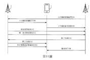
第11圖係為根據本發明之訊號傳送之示意圖;Figure 11 is a schematic diagram of signal transmission according to the present invention;
第12圖係為根據本發明之訊號傳送之示意圖;Figure 12 is a schematic diagram of signal transmission according to the present invention;
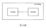
第13圖係為根據本發明之UE 1之示意圖;Figure 13 is a schematic diagram of
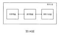
第14圖係為根據本發明之BS 2之示意圖;Figure 14 is a schematic diagram of
第15圖係為根據本發明之BS 3之示意圖。Figure 15 is a schematic diagram of
以下將透過本發明的某些實例性實施例來解釋本發明。該些實例性實施例並非用以限制本發明須在如該些實例性實施例中所述之任何特定的環境、實例、實施例、應用或特殊實施方式方能實施。因此,關於該些實例性實施例之說明僅為例示本發明之目的,而非用以限制本發明。Hereinafter, the present invention will be explained through some exemplary embodiments of the present invention. These exemplary embodiments are not intended to limit the implementation of the present invention in any specific environment, example, embodiment, application, or special implementation as described in these exemplary embodiments. Therefore, the description of these exemplary embodiments is only for the purpose of illustrating the present invention, rather than limiting the present invention.
應理解,在以下實施例及圖式中,與本發明非直接相關之部件已省略而未繪示。此外,圖式中各部件間之尺寸關係僅為求容易理解而例示,但並非用以限制實際比例。It should be understood that in the following embodiments and drawings, the parts that are not directly related to the present inventionParts have been omitted and not shown. In addition, the dimensional relationship between the components in the drawings is merely an illustration for ease of understanding, but is not intended to limit the actual ratio.
本發明之一第一實施例如第1圖至第2圖所示。為簡化描述,僅繪示單個使用者裝置(下稱「UE」)1、源BS 2及目標BS 3之間之訊號傳送作為示例,以描述在目標BS 3之時鐘定時與源BS 2之時鐘定時不同步之情況下,UE 1如何以低延遲執行自源BS 2至目標BS 3之無隨機存取通道(RACH)的切換。UE 1、源BS 2及目標BS 3相關之組件及組件之功能將分別詳述於第13圖至第15圖所對應之實施例中。本發明所屬技術領域中具有通常知識者應理解,UE 1亦可藉由執行與下文所述類似之操作來執行自源BS 2至其他目標BS之無RACH的切換,因此在本文中將不再予以贅述。A first embodiment of the present invention is shown in Figs. 1 to 2. To simplify the description, only the signal transmission between a single user device (hereinafter referred to as "UE") 1, the
行動通訊系統可為下一代行動通訊系統(目前廣義上稱為5G行動通訊系統)或基於正交分頻多重存取(orthogonal frequency division multiple access,OFDMA)技術之任何行動通訊系統。以下描述基於5G行動通訊系統來例示本發明;然而,本發明所屬技術領域中具有通常知識者應理解如何將本發明之技術手段延伸至應用於其他基於OFDMA之行動通訊系統,因此在本文中將不再予以贅述。The mobile communication system can be a next-generation mobile communication system (currently referred to as a 5G mobile communication system in a broad sense) or any mobile communication system based on orthogonal frequency division multiple access (OFDMA) technology. The following description exemplifies the present invention based on a 5G mobile communication system; however, those with ordinary knowledge in the technical field of the present invention should understand how to extend the technical means of the present invention to other OFDMA-based mobile communication systems. Therefore, in this article Do not repeat it.
第1圖繪示根據本發明之一行動通訊系統之實施情境。如第1圖所示,在行動通訊系統中,源BS 2具有一訊號覆蓋範圍C2,目標BS 3具有一訊號覆蓋範圍C3,且UE 1位於源BS 2及目標BS 3之訊號覆蓋範圍C2、C3兩者內。UE 1可為一智慧型電話、一平板電腦或任何無線通訊元件,例如支持超可靠低延遲通訊(URLLC)服務之UE(亦被稱為URLLC UE),或支持在切換過程中具有低延遲要求之任何服務,特別是支持0毫秒切換之UE,但並非僅限於此。Figure 1 shows an implementation scenario of a mobile communication system according to the present invention. As shown in Figure 1, in the mobile communication system, the
UE 1連接至源BS 2,因此UE 1已經獲得了源BS 2之一第一定時提前量(TA)值,並根據第一TA值與源BS 2達成了上行同步。當UE 1移動至訊號覆蓋範圍C2之邊緣區域並進入訊號覆蓋範圍C3時,自源BS 2接收之訊號之訊號品質及訊號強度將變弱,然後將觸發切換。為縮短傳送延遲,本發明之切換過程是無RACH的,尤其是在目標BS 3之時鐘定時與源BS 2之時鐘定時不同步之情況下。亦即,即使目標BS 3之時鐘定時與源BS 2之時鐘定時不同步,本發明之UE 1亦不需要在切換過程期間與目標BS 3執行RACH過程來保存訊令(signaling)。本發明之UE 1如何能夠獲得目標BS 3之一TA值以在無RACH過程之情況下與目標BS 3達成上行鏈路同步將詳細闡述如下。
請參照第2圖,UE 1接收用於自源BS 2至目標BS 3之切換指示之一無線電資源控制(RRC)連接重新配置訊息202。RRC連接重新配置訊息202由源BS 2產生,用於指示UE 1執行自源BS 2至目標BS 3之切換。此後,UE 1自源BS 2接收一第一同步訊號204,並自目標BS 3接收一第二同步訊號302。第一同步訊號204及第二同步訊號302各可為載於同步訊號塊(synchronization signal block,SSB)中之一主同步訊號(primary synchronization signal,PSS)及一次同步訊號(secondary synchronization signal,SSS)。UE 1計算第一同步訊號204之一第一接收時間與第二同步訊號302之一第二接收時間之間的一接收時間差,俾使UE 1可根據接收時間差導出目標BS 3相對於源BS 2之一延遲時間。Please refer to FIG. 2, the
若UE 1僅基於源BS 2之第一TA值及接收時間差來評估目標BS 3之第二TA值,則目標BS 3之第二TA值將不夠準確,此乃因目標BS 3之時鐘定時與源BS 2之時鐘定時不同步。因此,為補償由源BS 2與目標BS 3之間的不同步時鐘定時所導致的影響,UE 1更自源BS 2接收一第一參考時間資訊206,並自目標BS 3接收一第二參考時間資訊304。第一參考時間資訊206指示源BS 2之一第一訊框邊界處之一第一傳送時間,且第二參考時間資訊304指示目標BS 3之一第二訊框邊界處之一第二傳送時間。源BS 2之第一傳送時間與包含在由源BS 2傳送之一第一系統資訊塊(SIB)及一第一單播無線電資源控制(RRC)訊息其中之一中之一第一時間戳記相關聯,且目標BS 3之第二傳送時間與由目標BS 3傳送之一第二SIB及一第二單播RRC訊息其中之一的一第二時間戳記相關聯。If
接下來,UE 1計算第一傳送時間與第二傳送時間之間的一參考時間差,且基於第一TA值、接收時間差及參考時間差來計算目標BS 3之第二TA值,俾使可補償由源BS 2與目標BS 3之間的不同步時鐘定時所導致的影響。具體而言,藉由將接收時間差與相對於源BS 2之參考時間差相加,自第一TA值計算出第二TA值,其中接收時間差及參考時間差其中之每一者可為正的或負的。Next, the
本發明之一第二實施例如第3圖至第4圖所示。第二實施例係為第一實施例之延伸。在計算出目標BS 3之第二TA值之後,UE 1已與目標BS 3達成了上行鏈路同步。由於切換是無RACH的,因此UE 1不會自目標BS 3接收隨機存取響應(random access response,RAR)訊息來授權由RAR訊息指示之上行鏈路資源。在本發明中,目標BS 3會先(例如,經由X2介面)將其上行鏈路授權配置300傳送至源BS 2,且源BS 2將目標BS 3之上行鏈路授權配置300轉發至UE 1。換言之,由目標BS 3確定之上行鏈路授權配置300可藉由由源BS 2執行之轉發被傳送至UE 1。A second embodiment of the present invention is shown in Figs. 3 to 4. The second embodiment is an extension of the first embodiment. After calculating the second TA value of the
上行鏈路授權配置300可載於一RRC訊息或下行鏈路控制資訊(downlink control information,DCI)中。然而,在另一實施例中,由源BS 2轉發之上行鏈路授權配置300可載於RRC連接重新配置訊息202中(即,上行鏈路授權配置300可合併至由源BS 2傳送之RRC連接重新配置訊息202中)。The uplink grant configuration 300 can be contained in an RRC message or downlink control information (DCI). However, in another embodiment, the uplink authorization configuration 300 forwarded by the
此外,在其他實施例中,在切換過程完成後,UE 1自目標BS 3接收激活DCI 308,並激活載於一RRC訊息中之上行鏈路授權配置300,如第4圖所示。激活DCI 308與所配置授權辨識符(例如,所配置授權無線電網路臨時辨識符(configured grant radio network temporary identifier,CG-RNTI))相關聯。詳言之,上行鏈路授權配置300可與由目標BS 3分配之一或多個上行鏈路資源相關聯,俾使在接收到激活DCI 308之後,UE 1可將上行鏈路資源用於上行鏈路傳送。In addition, in other embodiments, after the handover process is completed, the
本發明之一第三實施例如第5圖所示。第三實施例係為第一實施例及第二實施例之延伸。不同於第二實施例,在本實施例中,上行鏈路授權配置200由源BS 2與目標BS 3協作來確定。A third embodiment of the present invention is shown in Fig. 5. The third embodiment is an extension of the first and second embodiments. Different from the second embodiment, in this embodiment, the uplink authorization configuration 200 is determined by the
詳言之,若當UE 1正基於先前自BS 2接收之上行鏈路授權配置200與源BS 2執行重覆傳送時源BS 2向UE 1指示自源BS 2至目標BS 3之切換,則有必要防止重覆傳送被中斷。因此,源BS 2與目標BS 3應協商上行鏈路授權配置200,以使在完成自源BS 2至目標BS 3之切換過程之後,UE 1能夠連續地傳送重覆上行鏈路訊號。In detail, if the
具體而言,上行鏈路授權配置200指示一重覆傳送數目(repetition transmission number),用於向源BS 2傳送重覆上行鏈路訊號102之一資源集以及用於向目標BS 3傳送重覆上行鏈路訊號104之一資源集,俾使在切換之後,UE 1能夠連續地與目標BS 3執行剩餘重覆傳送。Specifically, the uplink grant configuration 200 indicates a repetition transmission number for transmitting a resource set of the repetitive uplink signal 102 to the
在此種情況下,UE 1根據上行鏈路授權配置200將重覆上行鏈路訊號102(全部重覆上行鏈路訊號之一部分)傳送至源BS 2,且在完成自源BS 2至目標BS 3之切換之後,根據上行鏈路授權配置200將重覆上行鏈路訊號104(全部重覆上行鏈路訊號之剩餘部分)傳送至目標BS 3,如第5圖所示。In this case, the
類似地,上行鏈路授權配置200可載於一RRC訊息或下行鏈路控制資訊(DCI)中。此外,在另一實施例中,上行鏈路授權配置200可載於RRC連接重新配置訊息202中。Similarly, the uplink grant configuration 200 can be contained in an RRC message or downlink control information (DCI). In addition, in another embodiment, the uplink grant configuration 200 may be carried in the RRC connection reconfiguration message 202.
本發明之一第四實施例如第6圖所示。不同於第一實施例,在本實施例中,目標BS 3之第二TA值由源BS 2計算。A fourth embodiment of the present invention is shown in Fig. 6. Different from the first embodiment, in this embodiment, the second TA value of the
具體而言,UE 1傳送一上行鏈路參考訊號100,例如一解調參考訊號(demodulation reference signal,DMRS)或一探測參考訊號(sounding reference signal,SRS)。目標BS 3將量測由UE 1傳送之上行鏈路參考訊號100。在量測上行鏈路參考訊號100之後,目標BS 3記錄上行鏈路參考訊號100之接收時間,並將包含上行鏈路參考訊號100之接收時間之接收時間資訊310傳送至源BS 2。由於BS 2知曉由UE 1傳送之上行鏈路參考訊號100之傳送時間,因此BS 2可基於上行鏈路參考訊號100之接收時間及傳送時間來計算目標BS 3與UE 1之間的傳播延遲時間。Specifically, the
然而,由於源BS 2與目標BS 3之間不同步的時鐘定時,所計算的傳播延遲時間不準確。因此,在計算傳播延遲時間之後,源BS 2還需要基於源BS 2之第一參考時間與目標BS 3之第二參考時間來計算參考時間差,以補償傳播延遲時間的不準確性,俾使源BS 2可計算目標BS 3之第二TA值。However, due to the unsynchronized clock timing between the
詳言之,源BS 2自目標BS 3接收第二參考時間資訊304。第二參考時間資訊304指示目標BS 3之一第二訊框邊界處之第二參考時間。類似地,第一參考時間與源BS 2之一第一本地時鐘相關聯,該第一本地時鐘由包含在由源BS 2傳送之一第一SIB及一第一單播RRC訊息其中之一中之一第一時間戳記指示,且第二參考時間與目標BS 3之一第二本地時鐘相關聯,該第二本地時鐘由包含在由目標BS 3傳送之一第二SIB及一第二單播RRC訊息其中之一中之一第二時間戳記指示。應理解,傳送第二參考時間資訊304及接收時間資訊310之順序會被交換。In detail, the
源BS 2基於傳播延遲時間及參考時間差來計算目標BS 3之第二TA值,且將目標BS 3之第二TA值210傳送至UE 1,俾使可補償由源BS 2與目標BS 3之間的不同步時鐘定時所導致的影響。具體而言,第二TA值210係藉由將相對於源BS 2之參考時間差相加而自傳播延遲時間計算的,其中參考時間差可為正的或負的。同樣地,第二TA值210可載於RRC訊息、DCI及RRC連接重新配置訊息202其中之一中。The
在另一實施例中,參考時間差可由連接至源BS 2及目標BS 3之一回程元件(圖中未示出)計算,且被提供至源BS 2,俾使源BS 2在自回程元件接收到參考時間差之後計算第二TA值。In another embodiment, the reference time difference can be calculated by a backhaul element (not shown in the figure) connected to the
本發明之一第五實施例如第7圖所示。第五實施例為第四實施例之延伸。如在第二實施例中所述,由於切換是無RACH的,因此目標BS 3無法將其上行鏈路授權配置300直接傳送至UE 1。在此種情況下,目標BS 3只能將其上行鏈路授權配置300傳送至源BS 2,以使源BS 2將上行鏈路授權配置300轉發至UE 1。因此,在本實施例中,源BS 2更自目標BS 3接收目標BS 3之上行鏈路授權配置300,並將目標BS 3之上行鏈路授權配置300轉發至UE 1,以使UE 1基於上行鏈路授權配置300將上行鏈路訊號106傳送至目標BS 3。A fifth embodiment of the present invention is shown in Fig. 7. The fifth embodiment is the fourthAn extension of the example. As described in the second embodiment, since the handover is RACH-free, the
本發明之一第六實施例如第8圖所示。第六實施例為第四實施例及第五實施例之延伸。不同於第五實施例,在本實施例中,上行鏈路授權配置200由源BS 2與目標BS 3協作來確定。如在第三實施例中所述,源BS 2與目標BS 3可一起協商並確定上行鏈路授權配置200。上行鏈路授權配置200指示重覆傳送數目及用於由源BS 2接收重覆上行鏈路訊號102之資源集以及用於由目標BS 3接收重覆上行鏈路訊號104之資源集,俾使在切換之後,UE 1可連續地與目標BS 3執行剩餘重覆傳送。A sixth embodiment of the present invention is shown in Fig. 8. The sixth embodiment is an extension of the fourth embodiment and the fifth embodiment. Different from the fifth embodiment, in this embodiment, the uplink authorization configuration 200 is determined by the
在此種情況下,UE 1根據上行鏈路授權配置200將重覆上行鏈路訊號102(全部重覆上行鏈路訊號之一部分)傳送至源BS 2,且在完成自源BS 2至目標BS 3之切換之後,根據上行鏈路授權配置200將重覆上行鏈路訊號104(全部重覆上行鏈路訊號之剩餘部分)傳送至目標BS 3,如第8圖所示。In this case, the
本發明之一第七實施例如第9圖所示。不同於第一實施例,在本實施例中,目標BS 3之第二TA值由目標BS 3自身計算。UE 1已與源BS 2達成了上行鏈路同步,且目標BS 3之目標時鐘定時與源BS 2之源時鐘定時不同步。A seventh embodiment of the present invention is shown in Fig. 9. Different from the first embodiment, in this embodiment, the second TA value of the
為計算目標BS 3之第二TA值,目標BS 3量測上行鏈路參考訊號100,例如由UE 1傳送之DMRS或SRS,並記錄上行鏈路參考訊號100之接收時間。接下來,目標BS 3自源BS 2接收一傳送時間資訊212。傳送時間資訊指示UE 1向源BS 2傳送上行鏈路參考訊號100之傳送時間。應理解,上行鏈路參考訊號100及傳送時間資訊212之傳送順序會被交換。To calculate the second TA value of the
此後,目標BS 3基於上行鏈路參考訊號100之接收時間及傳送時間來計算目標BS 3與UE 1之間的傳播延遲時間。然而,由於源BS 2與目標BS 3之間不同步的時鐘定時,所計算的傳播延遲時間不準確。因此,在計算傳播延遲時間之後,目標BS 3自源BS 2接收指示源BS 2之一第一參考時間之一第一參考時間資訊214。第一參考時間與源BS 2之一第一本地時鐘相關聯,該第一本地時鐘由包含在由源BS 2傳送之一第一SIB及一第一單播RRC訊息其中之一中之一第一時間戳記指示,且第二參考時間與目標BS 3之一第二本地時鐘相關聯,該第二本地時鐘由包含在由目標BS 3傳送之一第二SIB及一第二單播RRC訊息其中之一中之一第二時間戳記指示。Thereafter, the
目標BS 3基於源BS 2之第一參考時間及目標BS 3之第二參考時間來計算參考時間差。此後,目標BS 3基於傳播延遲時間及參考時間差來計算目標BS 3之第二TA值,且將第二TA值312傳送至源BS 2,俾使源BS 2相應地將第二TA值312轉發至UE 1。具體而言,第二TA值312係藉由將相對於源BS 2之參考時間差相加而自傳播延遲時間計算的,其中參考時間差可為正的或負的。同樣地,由源BS 2傳送之第二TA值312可載於RRC訊息、DCI及RRC連接重新配置訊息202其中之一中。The
本發明之一第八實施例如第10圖至第11圖所示。第八實施例為第七實施例之延伸。同樣地,由於切換是無RACH的,因此目標BS 3只能將其上行鏈路授權配置300傳送至源BS 2,以使源BS 2將上行鏈路授權配置300轉發至UE 1。因此,在本實施例中,在目標BS 3確定其上行鏈路授權配置300之後,目標BS 3將上行鏈路授權配置300傳送至源BS 2,以供源BS 2將上行鏈路授權配置300轉發至UE 1。An eighth embodiment of the present invention is shown in Fig. 10 to Fig. 11. The eighth embodiment is an extension of the seventh embodiment. Similarly, since the handover is RACH-free, the
在另一實施例中,在切換過程完成之後,目標BS 3將與所配置授權辨識符相關聯之激活DCI 308傳送至UE 1,以激活載於RRC訊息中之上行鏈路授權配置300,如第11圖所示。In another embodiment, after the handover process is completed, the
本發明之一第九實施例如第12圖所示。第九實施例為第七實施例之延伸。不同於第八實施例,在本實施例中,目標BS 3與源BS 2協商上行鏈路授權配置200,並與源BS 2協作來確定上行鏈路授權配置200。然後,源BS 2將所確定的上行鏈路授權配置200傳送至UE 1。上行鏈路授權配置200指示重覆傳送數目及用於由源BS 2接收重覆上行鏈路訊號102之資源集以及用於由目標BS 3接收重覆上行鏈路訊號104之資源集,俾使在切換之後,UE 1可連續地與目標BS 3執行剩餘重覆傳送。A ninth embodiment of the present invention is shown in Fig. 12. The ninth embodiment is an extension of the seventh embodiment. Different from the eighth embodiment, in this embodiment, the
在此種情況下,UE 1根據上行鏈路授權配置200將重覆上行鏈路訊號102(全部重覆上行鏈路訊號之一部分)傳送至源BS 2,且在完成自源BS 2至目標BS 3之切換之後,根據上行鏈路授權配置200將重覆上行鏈路訊號104(全部重覆上行鏈路訊號之剩餘部分)傳送至目標BS 3,如第12圖所示。In this case, the
本發明之一第十實施例如第13圖所示,第13圖為根據本發明之UE 1之示意圖。UE 1包含一收發器11及一處理器13。處理器13電性連接至收發器11。為簡化描述,在圖式中未繪示UE 1之其他組件,例如儲存器、外殼、電源模組以及與本發明不太相關之其他組件。處理器13可為各種處理器、中央處理單元(Central Processing Unit,CPU)、微處理器、數位訊號處理器或本發明所屬技術領域中具有通常知識者已知之其他計算元件其中之任一者。A tenth embodiment of the present invention is shown in Fig. 13, which is according to the present inventionSchematic diagram of
對應於第一實施例,處理器13獲得源BS 2之第一TA值,且經由收發器11自源BS 2接收RRC連接重新配置訊息,用於自源BS 2切換至由RRC連接重新配置訊息指示之一目標BS 3。目標BS 3之目標時鐘定時與源BS 2之源時鐘定時不同步。處理器13計算由源BS 2傳送之第一同步訊號之第一接收時間與由目標BS 3傳送之第二同步訊號之第二接收時間之間的接收時間差。Corresponding to the first embodiment, the processor 13 obtains the first TA value of the
處理器13接收源BS 2之一第一參考時間資訊及目標BS 3之一第二參考時間資訊。第一參考時間資訊指示在源BS 2之第一訊框邊界處之第一傳送時間,且源BS 2之第一傳送時間與包含在由源BS 2傳送之第一SIB及第一單播RRC訊息其中之一中之第一時間戳記相關聯。第二參考時間資訊指示目標BS 3之第二訊框邊界處之第二傳送時間,且目標BS 3之第二傳送時間與由目標BS 3傳送之第二SIB及第二單播RRC訊息其中之一之第二時間戳記相關聯。The processor 13 receives the first reference time information of the
處理器13計算第一傳送時間與第二傳送時間之間的參考時間差。處理器13基於第一TA值、接收時間差及參考時間差來計算目標BS 3之第二TA值。The processor 13 calculates the reference time difference between the first transmission time and the second transmission time. The processor 13 calculates the second TA value of the
對應於第二實施例,處理器13經由收發器11自源BS 2接收目標BS 3之上行鏈路授權配置300。上行鏈路授權配置300載於一RRC訊息、DCI及RRC連接重新配置訊息其中之一中。上行鏈路授權配置由目標BS 3確定。Corresponding to the second embodiment, the processor 13 receives the uplink authorization configuration 300 of the
在其他實施例中,處理器13經由收發器11自目標BS 3接收激活DCI,並激活載於RRC訊息中之上行鏈路授權配置300。激活DCI與所配置授權辨識符相關聯。In other embodiments, the processor 13 receives the activated DCI from the
對應於第三實施例,處理器13經由收發器11自源BS 2接收上行鏈路授權配置200。上行鏈路授權配置200由源BS 2與目標BS 3協作來確定,且上行鏈路授權配置200指示重覆傳送數目及用於向源BS 2傳送一部分重覆上行鏈路訊號之資源集以及用於向目標BS 3傳送剩餘一部分重覆上行鏈路訊號之資源集。然後,處理器13根據上行鏈路授權配置200,經由收發器11將所述一部分重覆上行鏈路訊號傳送至源BS 2;且在完成自源BS 2至目標BS 3之切換之後,根據上行鏈路授權配置200,經由收發器11將所述剩餘一部分重覆上行鏈路訊號傳送至目標BS 3。Corresponding to the third embodiment, the processor 13 receives the uplink authorization configuration 200 from the
本發明之一第十一實施例如第14圖所示,第14圖為根據本發明之BS 2之示意圖。5G行動通訊系統中之BS 2通常被稱為「gBS」。BS 2為如在前述實施例中闡述之源BS 2,用於使UE 1執行自源BS 2至目標BS 3之切換。BS 2包含一收發器21、一網路介面23及一處理器25。處理器25電性連接至收發器21及網路介面23。應理解,為簡化描述,在圖式中未繪示BS 2之其他組件,例如儲存器、外殼、電源模組以及與本發明不太相關之其他組件。處理器25可為各種處理器、中央處理單元(CPU)、微處理器、數位訊號處理器或本發明所屬技術領域中具有通常知識者已知之其他計算元件其中之任一者。An eleventh embodiment of the present invention is shown in Fig. 14, which is a schematic diagram of the
對應於第四實施例,處理器25經由網路介面23自目標BS 3接收一上行鏈路參考訊號之一接收時間資訊。接收時間資訊由目標BS 3在量測由UE 1傳送之一上行鏈路參考訊號時產生。上行鏈路參考訊號為DMRS及SRS其中之一。Corresponding to the fourth embodiment, the processor 25 receives one of the uplink reference signals from the
接下來,處理器25基於由接收時間資訊指示之一接收時間及UE 1向BS 2傳送上行鏈路參考訊號之一傳送時間來計算目標BS 3之一傳播延遲時間。處理器25經由網路介面23自目標BS 3接收一參考時間資訊(即,第二參考時間資訊304)。參考時間資訊指示目標BS 3之一第二參考時間。Next, the processor 25 calculates a propagation delay time of the
此後,處理器25基於BS 2之第一參考時間及目標BS 3之第二參考時間來計算參考時間差。第一參考時間可與BS 2之第一本地時鐘相關聯,該第一本地時鐘由包含在由BS 2傳送之第一SIB及第一單播RRC訊息其中之一中之第一時間戳記指示,且第二參考時間可與目標BS 3之第二本地時鐘相關聯,該第二本地時鐘由包含在由目標BS 3傳送之第二SIB及第二單播RRC訊息其中之一中之第二時間戳記指示。Thereafter, the processor 25 calculates the reference time difference based on the first reference time of the
處理器25基於傳播延遲時間資訊及參考時間差來計算目標BS 3之第二TA值。處理器25經由收發器21將目標BS之第二TA值傳送至UE。第二TA值可載於一RRC訊息、下行鏈路控制資訊(DCI)及一RRC連接重新配置訊息其中之一中。The processor 25 calculates the second TA value of the
對應於第五實施例,處理器25經由網路介面23自目標BS 3接收由目標BS 3確定之上行鏈路授權配置300,且經由收發器21將目標BS 3之上行鏈路授權配置300轉發至UE 1,以使UE 1基於上行鏈路授權配置300將上行鏈路訊號傳送至目標BS 3。上行鏈路授權配置300載於RRC訊息、DCI及RRC連接重新配置訊息其中之一中。Corresponding to the fifth embodiment, the processor 25 receives the uplink authorization configuration 300 determined by the
對應於第六實施例,處理器25經由收發器21將上行鏈路授權配置200傳送至UE 1。上行鏈路授權配置200由BS 2與目標BS 3協作來確定,且上行鏈路授權配置200指示重覆傳送數目及用於自UE接收重覆上行鏈路訊號之一資源集。處理器25基於上行鏈路授權配置200經由收發器21自UE接收一部分重覆上行鏈路訊號。Corresponding to the sixth embodiment, the processor 25 transmits the uplink authorization configuration 200 to the
本發明之一第十二實施例如第15圖所示,第15圖為根據本發明之BS 3之示意圖。5G行動通訊系統中之BS 3通常被稱為「gNB」。BS 3為如在前述實施例中闡述之目標BS 3,用於使UE 1執行自源BS 2至目標BS 3之切換。BS 3之目標時鐘定時與源BS 2之一源時鐘定時不同步。UE 1已與源BS 2達成了上行鏈路同步。BS 3包含一收發器31、一網路介面33及一處理器35。處理器35電性連接至收發器31及網路介面33。應理解,為簡化描述,在圖式中未繪示BS 3之其他組件,例如儲存器、外殼、電源模組以及與本發明不太相關之其他組件。處理器35可為各種處理器、CPU、微處理器、數位訊號處理器或本發明所屬技術領域中具有通常知識者已知之其他計算元件其中之任一者。A twelfth embodiment of the present invention is shown in Fig. 15, which is a schematic diagram of
對應於第七實施例,處理器35量測由與源BS 2達成上行鏈路同步之UE 1經由網路介面33傳送之一上行鏈路參考訊號。處理器35記錄上行鏈路參考訊號之一接收時間。上行鏈路參考訊號為DMRS及SRS其中之一。接下來,處理器35經由網路介面33自源BS 2接收一傳送時間資訊。傳送時間資訊指示UE 1向源BS 2傳送上行鏈路參考訊號之一傳送時間。處理器35基於接收時間及傳送時間計算一傳播延遲時間。Corresponding to the seventh embodiment, the processor 35 measures an uplink reference signal transmitted by the
處理器35經由網路介面33自源BS 2接收一參考時間資訊(即,第一參考時間資訊214)。參考時間資訊指示源BS 2之一第一參考時間。第一參考時間與源BS 2之一第一本地時鐘相關聯,該第一本地時鐘由包含在由源BS 2傳送之第一SIB及第一單播RRC訊息其中之一中之第一時間戳記指示。此後,處理器35基於源BS 2之第一參考時間及BS 3之一第二參考時間計算參考時間差。第二參考時間與BS 3之第二本地時鐘相關聯,該第二本地時鐘由包含在由BS 3傳送之第二SIB及一第二單播RRC訊息其中之一中之第二時間戳記指示。The processor 35 receives a reference time information (ie, the first reference time information 214) from the
處理器35基於傳播延遲時間資訊及參考時間差來計算BS 3之第二TA值,且經由網路介面33將第二TA值傳送至源BS 2,以使源BS 2將第二TA值轉發至UE 1。第二TA值載於一RRC訊息、DCI及一RRC連接重新配置訊息其中之一中。The processor 35 calculates the second TA value of the
對應於第八實施例,處理器35確定BS 3之上行鏈路授權配置300,並經由網路介面33將上行鏈路授權配置300傳送至源BS 2,以使源BS 2將上行鏈路授權配置300轉發至UE 1。Corresponding to the eighth embodiment, the processor 35 determines the uplink authorization configuration 300 of the
在其他實施例中,處理器35更經由收發器31將與所配置授權辨識符相關聯之激活DCI傳送至UE 1,以激活載於RRC訊息中之上行鏈路授權配置300。In other embodiments, the processor 35 further transmits the activated DCI associated with the configured authorization identifier to the
對應於第九實施例,處理器35與源BS 2協作來確定上行鏈路授權配置300。上行鏈路授權配置300指示重覆傳送數目及用於自UE 1接收重覆上行鏈路訊號之一資源集。處理器35經由源BS 2將上行鏈路授權配置300傳送至UE 1,且在UE 1完成自源BS 2至BS 3之切換之後,基於上行鏈路授權配置300經由收發器31自UE 1接收剩餘一部分重覆上行鏈路訊號。Corresponding to the ninth embodiment, the processor 35 cooperates with the
綜上所述,當執行自源BS至目標BS之切換時,本發明使UE、源BS或目標BS計算TA值,用於使UE在無需與目標BS進行隨機存取過程之情況下達成與目標BS之上行鏈路同步。因此,在源BS之時鐘定時與目標BS之時鐘定時彼此不同步之情況下,本發明之UE能夠達成自源BS至目標BS之無RACH的切換。In summary, when performing handover from the source BS to the target BS, the present invention allows the UE, the source BS, or the target BS to calculate the TA value, which is used to enable the UE to achieve the same without the need to perform random access procedures with the target BS. The uplink synchronization of the target BS. Therefore, when the clock timing of the source BS and the clock timing of the target BS are not synchronized with each other, the UE of the present invention can achieve a RACH-free handover from the source BS to the target BS.
上述實施方式僅用來例舉本發明之部分實施態樣,以及闡釋本發明之技術特徵,而非用來限制本發明之保護範疇及範圍。任何本發明所屬技術領域中具有通常知識者可輕易完成之改變或均等性之安排均屬於本發明所主張之範圍,而本發明之權利保護範圍以申請專利範圍為準。The foregoing embodiments are only used to exemplify part of the implementation aspects of the present invention and to explain the technical features of the present invention, and are not used to limit the protection scope and scope of the present invention. Any change or equal arrangement that can be easily completed by a person with ordinary knowledge in the technical field of the present invention belongs to the scope of the present invention, and the protection scope of the present invention is subject to the scope of the patent application.
1:使用者裝置1: User device
2:基地台/源基地台2: Base station/source base station
3:基地台/目標基地台3: Base station/target base station
202:無線電資源控制連接重新配置訊息202: Radio resource control connection reconfiguration message
204:第一同步訊號204: The first sync signal
206:第一參考時間資訊206: First reference time information
302:第二同步訊號302: The second sync signal
304:第二參考時間資訊304: Second reference time information
Claims (20)
Translated fromChineseApplications Claiming Priority (3)
| Application Number | Priority Date | Filing Date | Title |
|---|---|---|---|
| US201962841787P | 2019-05-01 | 2019-05-01 | |
| US16/824,687 | 2020-03-19 | ||
| US16/824,687US11503515B2 (en) | 2019-05-01 | 2020-03-19 | User equipment and base station for mobile communication system |
Publications (2)
| Publication Number | Publication Date |
|---|---|
| TW202137797A TW202137797A (en) | 2021-10-01 |
| TWI747354Btrue TWI747354B (en) | 2021-11-21 |
Family
ID=73016799
Family Applications (1)
| Application Number | Title | Priority Date | Filing Date |
|---|---|---|---|
| TW109122248ATWI747354B (en) | 2019-05-01 | 2020-07-01 | User equipment and base station for mobile communication system |
Country Status (2)
| Country | Link |
|---|---|
| US (1) | US11503515B2 (en) |
| TW (1) | TWI747354B (en) |
Families Citing this family (11)
| Publication number | Priority date | Publication date | Assignee | Title |
|---|---|---|---|---|
| US11412505B2 (en)* | 2019-08-30 | 2022-08-09 | Qualcomm Incorporated | Techniques for a scheduled entity to adjust timing in wireless networks |
| CN114521340B (en)* | 2019-10-03 | 2024-06-11 | 索尼集团公司 | Communication apparatus, base station apparatus, and communication method |
| US11470567B2 (en)* | 2019-11-18 | 2022-10-11 | Qualcomm Incorporated | Network timing reference synchronization |
| CN111901864B (en)* | 2020-04-14 | 2025-08-19 | 中兴通讯股份有限公司 | Clock synchronization method, device and storage medium |
| JPWO2021251439A1 (en)* | 2020-06-10 | 2021-12-16 | ||
| US12389352B2 (en)* | 2020-07-30 | 2025-08-12 | Telefonaktiebolaget Lm Ericsson (Publ) | Reference time delivery during mobility operations in a time-sensitive network (TSN) |
| US11729736B2 (en)* | 2020-08-06 | 2023-08-15 | Samsung Electronics Co., Ltd. | Time adjustment during handover |
| WO2023010228A1 (en)* | 2021-07-31 | 2023-02-09 | Qualcomm Incorporated | Timing advance techniques for non-terrestrial network handovers |
| CN117202274A (en)* | 2022-05-30 | 2023-12-08 | 大唐移动通信设备有限公司 | Uplink synchronization method and device and related equipment thereof |
| CN117835336A (en)* | 2022-09-23 | 2024-04-05 | 华为技术有限公司 | Communication method, communication device and communication system |
| CN118945740A (en)* | 2023-05-11 | 2024-11-12 | 华为技术有限公司 | A communication method and device |
Citations (4)
| Publication number | Priority date | Publication date | Assignee | Title |
|---|---|---|---|---|
| CN103107849A (en)* | 2011-11-10 | 2013-05-15 | 财团法人工业技术研究院 | Control method, device and system of distributed antenna system |
| US20130279433A1 (en)* | 2012-04-20 | 2013-10-24 | Esmael Hejazi Dinan | Cell Timing in a Wireless Device and Base Station |
| TWI498024B (en)* | 2010-07-30 | 2015-08-21 | Ibm | Wireless communication system base station and data transmission synchronization method thereof |
| US20160227505A1 (en)* | 2011-03-08 | 2016-08-04 | Panasonic Intellectual Property Corporation Of America | Propagation delay difference reporting for multiple component carriers |
Family Cites Families (5)
| Publication number | Priority date | Publication date | Assignee | Title |
|---|---|---|---|---|
| US9307464B2 (en)* | 2007-06-21 | 2016-04-05 | Sony Corporation | Cellular communication system, apparatus and method for handover |
| US8774847B2 (en)* | 2011-07-27 | 2014-07-08 | Broadcom Corporation | Cellular radio path measurement and reporting |
| CN104737584B (en)* | 2012-10-19 | 2019-01-11 | 富士通互联科技有限公司 | Method and device for cell switching and reconfiguration |
| US10462713B2 (en) | 2014-10-30 | 2019-10-29 | Qualcomm Incorporated | Techniques for handover procedure management |
| US20180020472A1 (en)* | 2016-07-14 | 2018-01-18 | Nokia Technologies Oy | Handover mechanism with pre-scheduling consecutive grants and pre-calculated timing advance |
- 2020
- 2020-03-19USUS16/824,687patent/US11503515B2/enactiveActive
- 2020-07-01TWTW109122248Apatent/TWI747354B/enactive
Patent Citations (5)
| Publication number | Priority date | Publication date | Assignee | Title |
|---|---|---|---|---|
| TWI498024B (en)* | 2010-07-30 | 2015-08-21 | Ibm | Wireless communication system base station and data transmission synchronization method thereof |
| US20160227505A1 (en)* | 2011-03-08 | 2016-08-04 | Panasonic Intellectual Property Corporation Of America | Propagation delay difference reporting for multiple component carriers |
| CN103107849A (en)* | 2011-11-10 | 2013-05-15 | 财团法人工业技术研究院 | Control method, device and system of distributed antenna system |
| CN103107849B (en) | 2011-11-10 | 2016-03-16 | 财团法人工业技术研究院 | Control method, device and system of distributed antenna system |
| US20130279433A1 (en)* | 2012-04-20 | 2013-10-24 | Esmael Hejazi Dinan | Cell Timing in a Wireless Device and Base Station |
Also Published As
| Publication number | Publication date |
|---|---|
| US11503515B2 (en) | 2022-11-15 |
| US20200351728A1 (en) | 2020-11-05 |
| TW202137797A (en) | 2021-10-01 |
Similar Documents
| Publication | Publication Date | Title |
|---|---|---|
| TWI747354B (en) | User equipment and base station for mobile communication system | |
| CN105874856B (en) | A positioning method and device for TDD uplink and downlink different configurations | |
| US11432254B2 (en) | UE initiated propagation delay compensation mechanism | |
| CN109274475B (en) | Measurement method and communication device | |
| EP4336964A2 (en) | Inter-secondary node conditional cell change and measurement configuration | |
| JP2017517962A (en) | UE autonomous radio resource configuration extension | |
| CN111988099A (en) | Method, network side equipment, terminal and system for measuring cross link interference | |
| JP2021526777A (en) | Position measurement system for mobile terminals | |
| US20180295593A1 (en) | Communication system, base station, user equipment and timing synchronization method for base station thereof | |
| EP4233316A1 (en) | Configuration of periodic ue ul grant reporting over nrppa | |
| US20250133513A1 (en) | Wireless communication method, terminal device, and network device | |
| CN112055990B (en) | Link signal setting method for position measurement of mobile communication terminal | |
| EP3419350B1 (en) | Synchronization method and device between base stations | |
| CN107431960B (en) | Method and apparatus for radio network synchronization | |
| US20250071719A1 (en) | Positioning reference signal configuration and measurement update | |
| US20240323905A1 (en) | Positioning method and apparatus, terminal, and communication device | |
| EP4443990A1 (en) | Method for sl prs power control to avoid interference | |
| US20240107474A1 (en) | Rx-tx time difference generation, measurement and reporting with neighboring base stations | |
| CN111050383B (en) | Signal transmission method and device | |
| CN104955146B (en) | A kind of method for synchronizing time of LTE DMO terminals | |
| EP4277372B1 (en) | Apparatus, method, and computer program | |
| EP4362571A1 (en) | Positioning methods and apparatus, and electronic device | |
| EP4002915B1 (en) | Handover method, system for handover, and terminal device | |
| JP6865240B2 (en) | Base stations, communication systems, base station coordination methods and programs | |
| CN116321424A (en) | Link signal setting method for position measurement of mobile communication terminal |