TWI746476B - Separation of mixed xylenes - Google Patents
Separation of mixed xylenesDownload PDFInfo
- Publication number
- TWI746476B TWI746476BTW105135996ATW105135996ATWI746476BTW I746476 BTWI746476 BTW I746476BTW 105135996 ATW105135996 ATW 105135996ATW 105135996 ATW105135996 ATW 105135996ATW I746476 BTWI746476 BTW I746476B
- Authority
- TW
- Taiwan
- Prior art keywords
- xylene
- membrane
- membrane structure
- separation
- fluid communication
- Prior art date
Links
Images


Classifications
- B—PERFORMING OPERATIONS; TRANSPORTING
- B01—PHYSICAL OR CHEMICAL PROCESSES OR APPARATUS IN GENERAL
- B01D—SEPARATION
- B01D61/00—Processes of separation using semi-permeable membranes, e.g. dialysis, osmosis or ultrafiltration; Apparatus, accessories or auxiliary operations specially adapted therefor
- B01D61/02—Reverse osmosis; Hyperfiltration ; Nanofiltration
- B01D61/025—Reverse osmosis; Hyperfiltration
- B—PERFORMING OPERATIONS; TRANSPORTING
- B01—PHYSICAL OR CHEMICAL PROCESSES OR APPARATUS IN GENERAL
- B01D—SEPARATION
- B01D53/00—Separation of gases or vapours; Recovering vapours of volatile solvents from gases; Chemical or biological purification of waste gases, e.g. engine exhaust gases, smoke, fumes, flue gases, aerosols
- B01D53/22—Separation of gases or vapours; Recovering vapours of volatile solvents from gases; Chemical or biological purification of waste gases, e.g. engine exhaust gases, smoke, fumes, flue gases, aerosols by diffusion
- B01D53/228—Separation of gases or vapours; Recovering vapours of volatile solvents from gases; Chemical or biological purification of waste gases, e.g. engine exhaust gases, smoke, fumes, flue gases, aerosols by diffusion characterised by specific membranes
- B—PERFORMING OPERATIONS; TRANSPORTING
- B01—PHYSICAL OR CHEMICAL PROCESSES OR APPARATUS IN GENERAL
- B01D—SEPARATION
- B01D61/00—Processes of separation using semi-permeable membranes, e.g. dialysis, osmosis or ultrafiltration; Apparatus, accessories or auxiliary operations specially adapted therefor
- B01D61/002—Forward osmosis or direct osmosis
- B—PERFORMING OPERATIONS; TRANSPORTING
- B01—PHYSICAL OR CHEMICAL PROCESSES OR APPARATUS IN GENERAL
- B01D—SEPARATION
- B01D61/00—Processes of separation using semi-permeable membranes, e.g. dialysis, osmosis or ultrafiltration; Apparatus, accessories or auxiliary operations specially adapted therefor
- B01D61/007—Separation by stereostructure, steric separation
- B—PERFORMING OPERATIONS; TRANSPORTING
- B01—PHYSICAL OR CHEMICAL PROCESSES OR APPARATUS IN GENERAL
- B01D—SEPARATION
- B01D67/00—Processes specially adapted for manufacturing semi-permeable membranes for separation processes or apparatus
- B01D67/0039—Inorganic membrane manufacture
- B01D67/0067—Inorganic membrane manufacture by carbonisation or pyrolysis
- B—PERFORMING OPERATIONS; TRANSPORTING
- B01—PHYSICAL OR CHEMICAL PROCESSES OR APPARATUS IN GENERAL
- B01D—SEPARATION
- B01D69/00—Semi-permeable membranes for separation processes or apparatus characterised by their form, structure or properties; Manufacturing processes specially adapted therefor
- B01D69/08—Hollow fibre membranes
- B—PERFORMING OPERATIONS; TRANSPORTING
- B01—PHYSICAL OR CHEMICAL PROCESSES OR APPARATUS IN GENERAL
- B01D—SEPARATION
- B01D69/00—Semi-permeable membranes for separation processes or apparatus characterised by their form, structure or properties; Manufacturing processes specially adapted therefor
- B01D69/12—Composite membranes; Ultra-thin membranes
- B01D69/1213—Laminated layers
- B—PERFORMING OPERATIONS; TRANSPORTING
- B01—PHYSICAL OR CHEMICAL PROCESSES OR APPARATUS IN GENERAL
- B01D—SEPARATION
- B01D69/00—Semi-permeable membranes for separation processes or apparatus characterised by their form, structure or properties; Manufacturing processes specially adapted therefor
- B01D69/12—Composite membranes; Ultra-thin membranes
- B01D69/1218—Layers having the same chemical composition, but different properties, e.g. pore size, molecular weight or porosity
- B—PERFORMING OPERATIONS; TRANSPORTING
- B01—PHYSICAL OR CHEMICAL PROCESSES OR APPARATUS IN GENERAL
- B01D—SEPARATION
- B01D69/00—Semi-permeable membranes for separation processes or apparatus characterised by their form, structure or properties; Manufacturing processes specially adapted therefor
- B01D69/12—Composite membranes; Ultra-thin membranes
- B01D69/125—In situ manufacturing by polymerisation, polycondensation, cross-linking or chemical reaction
- B—PERFORMING OPERATIONS; TRANSPORTING
- B01—PHYSICAL OR CHEMICAL PROCESSES OR APPARATUS IN GENERAL
- B01D—SEPARATION
- B01D71/00—Semi-permeable membranes for separation processes or apparatus characterised by the material; Manufacturing processes specially adapted therefor
- B01D71/02—Inorganic material
- B01D71/021—Carbon
- B—PERFORMING OPERATIONS; TRANSPORTING
- B01—PHYSICAL OR CHEMICAL PROCESSES OR APPARATUS IN GENERAL
- B01D—SEPARATION
- B01D71/00—Semi-permeable membranes for separation processes or apparatus characterised by the material; Manufacturing processes specially adapted therefor
- B01D71/02—Inorganic material
- B01D71/022—Metals
- B01D71/0223—Group 8, 9 or 10 metals
- B01D71/02231—Palladium
- B—PERFORMING OPERATIONS; TRANSPORTING
- B01—PHYSICAL OR CHEMICAL PROCESSES OR APPARATUS IN GENERAL
- B01D—SEPARATION
- B01D71/00—Semi-permeable membranes for separation processes or apparatus characterised by the material; Manufacturing processes specially adapted therefor
- B01D71/02—Inorganic material
- B01D71/022—Metals
- B01D71/0223—Group 8, 9 or 10 metals
- B01D71/02232—Nickel
- C—CHEMISTRY; METALLURGY
- C02—TREATMENT OF WATER, WASTE WATER, SEWAGE, OR SLUDGE
- C02F—TREATMENT OF WATER, WASTE WATER, SEWAGE, OR SLUDGE
- C02F1/00—Treatment of water, waste water, or sewage
- C02F1/44—Treatment of water, waste water, or sewage by dialysis, osmosis or reverse osmosis
- C02F1/441—Treatment of water, waste water, or sewage by dialysis, osmosis or reverse osmosis by reverse osmosis
- C—CHEMISTRY; METALLURGY
- C07—ORGANIC CHEMISTRY
- C07C—ACYCLIC OR CARBOCYCLIC COMPOUNDS
- C07C15/00—Cyclic hydrocarbons containing only six-membered aromatic rings as cyclic parts
- C07C15/02—Monocyclic hydrocarbons
- C07C15/067—C8H10 hydrocarbons
- C07C15/08—Xylenes
- C—CHEMISTRY; METALLURGY
- C07—ORGANIC CHEMISTRY
- C07C—ACYCLIC OR CARBOCYCLIC COMPOUNDS
- C07C5/00—Preparation of hydrocarbons from hydrocarbons containing the same number of carbon atoms
- C07C5/22—Preparation of hydrocarbons from hydrocarbons containing the same number of carbon atoms by isomerisation
- C07C5/27—Rearrangement of carbon atoms in the hydrocarbon skeleton
- C07C5/2729—Changing the branching point of an open chain or the point of substitution on a ring
- C07C5/2732—Catalytic processes
- C—CHEMISTRY; METALLURGY
- C07—ORGANIC CHEMISTRY
- C07C—ACYCLIC OR CARBOCYCLIC COMPOUNDS
- C07C7/00—Purification; Separation; Use of additives
- C07C7/005—Processes comprising at least two steps in series
- C—CHEMISTRY; METALLURGY
- C07—ORGANIC CHEMISTRY
- C07C—ACYCLIC OR CARBOCYCLIC COMPOUNDS
- C07C7/00—Purification; Separation; Use of additives
- C07C7/14—Purification; Separation; Use of additives by crystallisation; Purification or separation of the crystals
- C—CHEMISTRY; METALLURGY
- C07—ORGANIC CHEMISTRY
- C07C—ACYCLIC OR CARBOCYCLIC COMPOUNDS
- C07C7/00—Purification; Separation; Use of additives
- C07C7/144—Purification; Separation; Use of additives using membranes, e.g. selective permeation
- B—PERFORMING OPERATIONS; TRANSPORTING
- B01—PHYSICAL OR CHEMICAL PROCESSES OR APPARATUS IN GENERAL
- B01D—SEPARATION
- B01D2323/00—Details relating to membrane preparation
- B01D2323/30—Cross-linking
- B—PERFORMING OPERATIONS; TRANSPORTING
- B01—PHYSICAL OR CHEMICAL PROCESSES OR APPARATUS IN GENERAL
- B01D—SEPARATION
- B01D2325/00—Details relating to properties of membranes
- B01D2325/02—Details relating to pores or porosity of the membranes
- B01D2325/022—Asymmetric membranes
- B—PERFORMING OPERATIONS; TRANSPORTING
- B01—PHYSICAL OR CHEMICAL PROCESSES OR APPARATUS IN GENERAL
- B01D—SEPARATION
- B01D2325/00—Details relating to properties of membranes
- B01D2325/04—Characteristic thickness
- C—CHEMISTRY; METALLURGY
- C02—TREATMENT OF WATER, WASTE WATER, SEWAGE, OR SLUDGE
- C02F—TREATMENT OF WATER, WASTE WATER, SEWAGE, OR SLUDGE
- C02F2103/00—Nature of the water, waste water, sewage or sludge to be treated
- C02F2103/08—Seawater, e.g. for desalination
- Y—GENERAL TAGGING OF NEW TECHNOLOGICAL DEVELOPMENTS; GENERAL TAGGING OF CROSS-SECTIONAL TECHNOLOGIES SPANNING OVER SEVERAL SECTIONS OF THE IPC; TECHNICAL SUBJECTS COVERED BY FORMER USPC CROSS-REFERENCE ART COLLECTIONS [XRACs] AND DIGESTS
- Y02—TECHNOLOGIES OR APPLICATIONS FOR MITIGATION OR ADAPTATION AGAINST CLIMATE CHANGE
- Y02P—CLIMATE CHANGE MITIGATION TECHNOLOGIES IN THE PRODUCTION OR PROCESSING OF GOODS
- Y02P20/00—Technologies relating to chemical industry
- Y02P20/50—Improvements relating to the production of bulk chemicals
- Y02P20/52—Improvements relating to the production of bulk chemicals using catalysts, e.g. selective catalysts
Landscapes
- Chemical & Material Sciences (AREA)
- Chemical Kinetics & Catalysis (AREA)
- Organic Chemistry (AREA)
- Engineering & Computer Science (AREA)
- Water Supply & Treatment (AREA)
- Inorganic Chemistry (AREA)
- Analytical Chemistry (AREA)
- Oil, Petroleum & Natural Gas (AREA)
- General Chemical & Material Sciences (AREA)
- Nanotechnology (AREA)
- Crystallography & Structural Chemistry (AREA)
- Manufacturing & Machinery (AREA)
- Environmental & Geological Engineering (AREA)
- Hydrology & Water Resources (AREA)
- Life Sciences & Earth Sciences (AREA)
- Separation Using Semi-Permeable Membranes (AREA)
- Organic Low-Molecular-Weight Compounds And Preparation Thereof (AREA)
- Carbon And Carbon Compounds (AREA)
- Low-Molecular Organic Synthesis Reactions Using Catalysts (AREA)
- Catalysts (AREA)
- Macromolecular Compounds Obtained By Forming Nitrogen-Containing Linkages In General (AREA)
Abstract
Description
Translated fromChinese本說明書關於部分基於各種化合物之逆滲透膜分離(reverse osmosis membrane separation)的混合之二甲苯的處理及分離。This specification is about the treatment and separation of mixed xylene based partly on the reverse osmosis membrane separation of various compounds.
許多石油精製及化學製造方法包括一或多種用於分離所欲產物之分離方法。膜分離係由於進行分離的低能量需求而為有潛在希望的分離方法。然而,使用膜分離受限於其中適合的膜為可用於進行商業規模的分離之情形。Many petroleum refining and chemical manufacturing methods include one or more separation methods for separating desired products. Membrane separation systems are a potentially promising separation method due to the low energy requirements for separation. However, the use of membrane separation is limited to situations where suitable membranes are available for commercial-scale separations.
對-二甲苯(para-xylene)與其他的C8芳族的分離為難以經由沸點分離來進行分離的實例。目前的商業方法包含選擇性結晶(selective crystallization)或模擬移動床層析術(simulated moving bed chromatography)以分離對-二甲苯與鄰-和間-二甲苯。該等方法為極需能量及/或設備的方法。The separation of para-xylene from other C8 aromatics is an example of difficulty in separation via boiling point separation. Current commercial methods include selective crystallization or simulated moving bed chromatography to separate para-xylene from ortho- and meta-xylene. These methods are methods that require much energy and/or equipment.
美國專利4,510,047說明用於含烴化合物(hydrocarbonaceous compound)(諸如芳族萃取溶劑)的逆滲透分離之再生纖維素膜。再生纖維素膜在此等溶劑的存在下易於孔膨脹。U.S. Patent 4,510,047 describes the use of hydrocarbon compoundsRegenerated cellulose membrane for reverse osmosis separation of hydrocarbonaceous compounds (such as aromatic extraction solvents). Regenerated cellulose membranes are prone to pore swelling in the presence of these solvents.
美國專利4,571,444說明使用不對稱聚醯亞胺纖維膜分離烷基芳族化合物與芳族溶劑之方法。該膜係描述為適合於至少部分分離苯、甲苯及/或乙苯與經C8至C20烷基所烷基化之單環芳族化合物。U.S. Patent No. 4,571,444 describes the use of asymmetric polyimide fiber membranes to separate alkyl aromatic compounds and aromatic solvents. The membrane system is described as being suitable for at least partially separating benzene, toluene and/or ethylbenzene from monocyclic aromatic compounds alkylatedby C 8 to C20 alkyl groups.
在各種態樣中,提供用於進行二甲苯異構化(isomerization)及/或分離之系統及方法。例如,在一態樣中,用於二甲苯異構化及分離之系統可包括基於沸點分離(boiling point separation)之分離階段,用以產生至少一富含對-二甲苯餾份(para-xylene enriched fraction);與分離階段流體連通的二甲苯回收單元,以接收來自分離階段之富含對-二甲苯餾份,該二甲苯回收單元包含產物出口及殘餘物出口;與殘餘物出口流體連通的膜結構,以接收至少一部分的殘餘物流;以及與膜結構流體連通的液相異構化反應器,以接收來自膜結構的阻留物(retentate)。In various aspects, systems and methods for xylene isomerization and/or separation are provided. For example, in one aspect, the system for xylene isomerization and separation may include a separation stage based on boiling point separation to generate at least one para-xylene-rich fraction (para-xylene). enriched fraction); a xylene recovery unit in fluid communication with the separation stage to receive the enriched p-xylene fraction from the separation stage, the xylene recovery unit including a product outlet and a residue outlet; fluidly connected with the residue outlet A membrane structure to receive at least a portion of the residual stream; and a liquid phase isomerization reactor in fluid communication with the membrane structure to receive retentate from the membrane structure.
在另一態樣中,用於二甲苯異構化及分離之系統可包括基於沸點分離之分離階段,用以產生至少一富含對-二甲苯餾份;至少一個膜結構,以形成包含對-二甲苯之滲透物(permeate)及阻留物;以及與膜結構流體連通的異構化反應器,以接收來自膜結構的阻留物。In another aspect, the system for xylene isomerization and separation may include a separation stage based on boiling point separation to produce at least one p-xylene-rich fraction; at least one membrane structure to form a -Permeate and retentate of xylene; and an isomerization reactor in fluid communication with the membrane structure to receive the retentate from the membrane structure.
在又另一態樣中,用於二甲苯異構化及分離之方法可包括使含二甲苯之進料在液相異構化條件下接觸異構化觸媒,以產生異構化流出物(isomerized effluent);以及對至少一部分的異構化流出物進行膜分離,以產生相對於含二甲苯之進料及異構化流出物而言富含對-二甲苯之滲透物。In yet another aspect, the method for xylene isomerization and separation may include contacting a feed containing xylene with an isomerization catalyst under liquid phase isomerization conditions to produce an isomerized effluent (isomerized effluent); and membrane separation is performed on at least a portion of the isomerized effluent to produce a permeate rich in p-xylene relative to the xylene-containing feed and the isomerized effluent.
在一些態樣中,膜結構可相應於包含複數個膜層的膜結構。第一膜層具有孔體積為至少0.2cm3/g、中值孔徑(median pore size)為至少20nm之孔,第二膜層包含具有BET表面積為至少約100m2/g(或至少約300m2/g)之多孔碳層,第二膜層具有包含中值孔徑為約5.8埃至約7.0埃之最小實質孔徑峰(smallest substantial pore size peak)的孔徑分布(pore size distribution)。最小實質孔徑峰可隨意地具有約5.8埃至約6.8埃、或約6.0至約6.5埃之中值孔徑。膜結構可隨意地相應於中空纖維膜結構(hollow fiber membrane structure)。In some aspects, the film structure may correspond to a film structure including a plurality of film layers. The first membrane layer has pores with a pore volume of at least 0.2 cm3 /g and a median pore size of at least 20 nm, and the second membrane layer includes pores with a BET surface area of at least about 100 m2 /g (or at least about 300 m2 /g) porous carbon layer, the second membrane layer has a pore size distribution including a smallest substantial pore size peak with a median pore diameter of about 5.8 angstroms to about 7.0 angstroms. The minimum substantial pore diameter peak can optionally have a median pore diameter of about 5.8 angstroms to about 6.8 angstroms, or about 6.0 to about 6.5 angstroms. The membrane structure can optionally correspond to the hollow fiber membrane structure.
110‧‧‧輸入流110‧‧‧input stream
120、880‧‧‧蒸餾塔120、880‧‧‧Distillation tower
123、323‧‧‧C8化合物123, 323‧‧‧C8 compound
125‧‧‧高沸點化合物125‧‧‧High boiling point compounds
130、830‧‧‧對-二甲苯回收單元130, 830‧‧‧p-xylene recovery unit
133、233、433‧‧‧高純度對-二甲苯流133, 233, 433‧‧‧High purity p-xylene stream
135、235、335‧‧‧萃餘物135, 235, 335‧‧‧Remnant
140‧‧‧異構化單元140‧‧‧Isomerization unit
141‧‧‧氫輸入流141‧‧‧Hydrogen input stream
145、845‧‧‧異構化流出物145、845‧‧‧Isomerization effluent
147‧‧‧苯/甲苯147‧‧‧Benzene/Toluene
149‧‧‧輕氣體149‧‧‧Light gas
250、360、460、461、462‧‧‧烴逆滲透膜250, 360, 460, 461, 462‧‧‧hydrocarbon reverse osmosis membrane
363‧‧‧富含對-二甲苯流363‧‧‧rich p-xylene stream
435、468、469、855‧‧‧阻留物流435, 468, 469, 855‧‧‧ to block logistics
810‧‧‧含二甲苯之進料810‧‧‧Feed material containing xylene
820‧‧‧分餾器820‧‧‧ Fractionator
823‧‧‧富含二甲苯流823‧‧‧Enriched xylene stream
829‧‧‧輕質餾份829‧‧‧Light Distillate
833‧‧‧對-二甲苯產物流833‧‧‧p-xylene product stream
835‧‧‧殘餘物流835‧‧‧Residual logistics
840‧‧‧液相液構化反應器840‧‧‧liquid phase liquefaction reactor
850‧‧‧選擇性膜850‧‧‧Selective membrane
855‧‧‧滲透物855‧‧‧Permeate
882‧‧‧低沸餾份882‧‧‧Low boiling fraction
887‧‧‧底部餾份887‧‧‧Bottom Distillate
圖1係圖示用於自混合之芳族輸入流分離高純度對-二甲苯流之製程配置。Figure 1 illustrates the process configuration used to separate high-purity para-xylene streams from mixed aromatic input streams.
圖2係圖示包括用於自混合之芳族輸入流分離高純度對-二甲苯流之烴逆滲透膜的製程配置。Figure 2 is a diagrammatic representation of a process configuration including a hydrocarbon reverse osmosis membrane used to separate a high-purity para-xylene stream from a mixed aromatic input stream.
圖3係圖示包括用於自混合之芳族輸入流分離高純度對-二甲苯流之烴逆滲透膜的製程配置。Figure 3 shows a schematic diagram of a process configuration including a hydrocarbon reverse osmosis membrane used to separate high-purity para-xylene streams from mixed aromatic input streams.
圖4係圖示包括用於自混合之芳族輸入流分離高純度對-二甲苯流之烴逆滲透膜的製程配置。Figure 4 is a diagrammatic representation of a process configuration including a hydrocarbon reverse osmosis membrane used to separate a high-purity para-xylene stream from a mixed aromatic input stream.
圖5顯示不對稱膜結構的實例。Figure 5 shows an example of an asymmetric membrane structure.
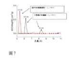
圖6顯示由未交聯之聚偏二氟乙烯(non-cross-linked polyvinylidene fluoride)所形成的膜結構(在熱解(pyrolysis)前及後)的實例。Figure 6 shows an example of a film structure (before and after pyrolysis) formed by non-cross-linked polyvinylidene fluoride.
圖7係圖示藉由聚偏二氟乙烯膜結構(有及無預交聯(prior cross-linking))之熱解所形成的多孔碳膜結構之孔徑分布的實例。FIG. 7 illustrates an example of the pore size distribution of the porous carbon membrane structure formed by the pyrolysis of the polyvinylidene fluoride membrane structure (with and without prior cross-linking).
圖8顯示於聚偏二氟乙烯及多孔碳膜結構之N2物理吸附的實例。Figure 8 shows an exampleof N 2 physical adsorption on polyvinylidene fluoride and porous carbon membrane structure.
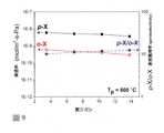
圖9顯示各種單環芳族化合物之關於不對稱多孔碳膜結構的單一組份滲透率值(permeance value)。Figure 9 shows the permeance value of a single component with respect to the structure of the asymmetric porous carbon membrane of various monocyclic aromatic compounds.
圖10顯示各種單環芳族化合物之關於不對稱多孔碳膜結構的單一組份滲透率值。Figure 10 shows the single-component permeability values of various monocyclic aromatic compounds with respect to the structure of the asymmetric porous carbon membrane.
圖11顯示對-二甲苯和鄰-二甲苯之關於不對稱多孔碳膜結構的擴散率值(diffusivity value)。Figure 11 shows the diffusivity values of p-xylene and o-xylene with respect to the structure of the asymmetric porous carbon membrane.
圖12顯示對-二甲苯和鄰-二甲苯之關於不對稱多孔碳膜結構的為壓力之函數的吸附。Figure 12 shows the adsorption of p-xylene and o-xylene on the asymmetric porous carbon membrane structure as a function of pressure.
圖13顯示對-二甲苯與鄰-二甲苯之50:50及90:10混合物的烴逆滲透分離的結果。Figure 13 shows the results of reverse osmosis separation of hydrocarbons of 50:50 and 90:10 mixtures of p-xylene and o-xylene.
圖14顯示對-二甲苯與鄰-二甲苯之50:50及90:10混合物的烴逆滲透分離的結果。Figure 14 shows the results of reverse osmosis separation of hydrocarbons of 50:50 and 90:10 mixtures of p-xylene and o-xylene.
圖15顯示對-二甲苯與鄰-二甲苯之50:50及90:10混合物的烴逆滲透分離的結果。Figure 15 shows the 50:50 ratio of p-xylene and o-xylene90: 10 result of reverse osmosis separation of hydrocarbons.
圖16顯示有及無交聯之聚偏二氟乙烯膜結構之儲存模數值。Figure 16 shows the storage modulus values of polyvinylidene fluoride membrane structures with and without crosslinking.
圖17顯示由擠壓金屬粒子與聚合物黏合劑的混合物所形成之擠壓結構的實例。Figure 17 shows an example of an extruded structure formed by extruding a mixture of metal particles and a polymer binder.
圖18顯示藉由燒結圖17的擠壓結構所形成之多孔金屬結構。FIG. 18 shows a porous metal structure formed by sintering the extruded structure of FIG. 17.
圖19顯示多孔金屬結構之孔徑分布。Figure 19 shows the pore size distribution of the porous metal structure.
圖20顯示不對稱膜結構的實例。Figure 20 shows an example of an asymmetric membrane structure.
圖21顯示甲苯和正庚烷的通過不對稱膜結構之單一組份滲透率的實例。Figure 21 shows an example of the single component permeability of toluene and n-heptane through an asymmetric membrane structure.
圖22係圖示包括用於自混合之芳族輸入流分離高純度對-二甲苯流之烴逆滲透膜的製程配置。Figure 22 illustrates a process configuration including a hydrocarbon reverse osmosis membrane used to separate high-purity para-xylene streams from mixed aromatic input streams.
在各種態樣中,提供適合於例如小型烴(small hydrocarbon)之烴逆滲透(hydrocarbon reverse osmosis)的不對稱膜結構。在一具體實例中,不對稱膜結構可具有適合於將對-二甲苯(para-xylene(p-xylene))與鄰-二甲苯(ortho-xylene(o-xylene))和間-二甲苯(meta-xylene (m-xylene))分離之具最小或控制孔徑的非晶形孔網絡(amorphous pore network)。亦提供由聚偏二氟乙烯(polyvinylidene fluoride)(或另一部分氟化之單體)製造不對稱膜結構之方法。適合的不對稱膜結構的實例可為中空纖維膜(hollow fiber membrane)。當使用聚合物形成膜結構時,膜結構可隨後於使用之前交聯及/或熱解(pyrolyze)。在一些態樣中,膜結構之交聯可穩定膜結構的各種部位,使得在隨後的熱解步驟(pyrolysis step)期間達成及/或維持所欲性質。在一些態樣中,聚合物可在熱解後保留所欲孔結構而不需要預交聯(prior cross-linking)。接著可利用熱解將聚合物膜結構(polymeric membrane structure)轉化成具有較高的碳對氫之比的多孔碳結構(porous carbon structure)。In various aspects, an asymmetric membrane structure suitable for hydrocarbon reverse osmosis such as small hydrocarbons is provided. In a specific example, the asymmetric membrane structure may have a structure suitable for combining para-xylene (p-xylene) with ortho-xylene (o-xylene) and meta-xylene ( Meta-xylene (m-xylene)) separated amorphous pore network (amorphous pore network) with the smallest or controlled pore size. It also provides a method for making an asymmetric membrane structure from polyvinylidene fluoride (or another partially fluorinated monomer). Examples of suitable asymmetric membrane structures can be mediumHollow fiber membrane. When a polymer is used to form a film structure, the film structure can be subsequently cross-linked and/or pyrolyzed before use. In some aspects, the cross-linking of the membrane structure can stabilize various parts of the membrane structure so that the desired properties are achieved and/or maintained during the subsequent pyrolysis step. In some aspects, the polymer can retain the desired pore structure after pyrolysis without prior cross-linking. Then, pyrolysis can be used to convert the polymeric membrane structure into a porous carbon structure with a higher ratio of carbon to hydrogen.
在此論述中,記號〝Cx〞係指具有至少50重量%之含有〝x〞碳數的烴之烴流。記號〝Cx+〞係指具有至少50重量%之含有〝x〞或更多碳的烴之烴流。就該等定義,烴流係定義為包括了在流中的至少一部分化合物係含有除了碳和氫以外的雜原子之流。In this discussion, the symbol "Cx "refers to a hydrocarbon stream having at least 50% by weight of hydrocarbons containing a carbon number of "x". The symbol "Cx+ "refers to a hydrocarbon stream having at least 50% by weight of hydrocarbons containing "x" or more carbon. For these definitions, a hydrocarbon stream is defined as a stream that includes at least a part of the compounds in the stream containing heteroatoms other than carbon and hydrogen.
在此論述中,基於沸點分離之分離階段係指包括一或多個用於進行基於蒸餾(distillation)、分餾(fractionation)、驟蒸分離(flash separation)、氣-液分離(gas-liquid separation)及/或其他分離方法之分離的分離器之分離階段,其中所得經分離部分的組成實質上取決於分離階段之進料的組份在分離條件下的蒸氣壓而定。這與膜分離成對比,膜分離(取決於進料本質)有可能產生實質上具有相似的沸點範圍的經分離部分。In this discussion, the separation stage based on boiling point separation refers to one or more stages for performing distillation, fractionation, flash separation, and gas-liquid separation. And/or the separation stage of the separated separator of other separation methods, in which the composition of the obtained separated part is substantially determined by the vapor pressure of the components of the feed in the separation stage under the separation conditions. This is in contrast to membrane separation, which (depending on the nature of the feed) may produce separated fractions that have substantially similar boiling point ranges.
在各種態樣中,本文所述之膜可相應於具有不對稱膜結構之膜。在不對稱膜結構中,第一膜層可相應於多孔支撐層(porous support layer),而第二膜層可相應於選擇層(selective layer)。第二膜層或選擇層可相應於膜分離期間接觸進料之層。在先使用聚合物形成至少一部分的膜結構之態樣中,在此章節中所述之性質相應於在任何交聯及/或熱解後的膜結構之性質,除非另有指明。In various aspects, the membranes described herein can correspond to membranes having an asymmetric membrane structure. In an asymmetric membrane structure, the first membrane layer may correspond to a porous support layer, and the second membrane layer may correspond to a selective layer. The second membrane layer or selective layer may correspond to the layer that contacts the feed during membrane separation. In the case of using polymers to form at least a portion of the film structure, the properties described in this section correspond to the properties of the film structure after any crosslinking and/or pyrolysis, unless otherwise specified.
第二膜層或選擇層可具有非晶形互連之孔結構(amorphous interconnected pore structure)。非晶形互連之孔結構可容許化合物在適合於烴逆滲透的條件下基於分子大小而選擇性分離(selective separation)。因為在分離期間滲透物質通過選擇層係有所受限,所以選擇層可相對薄以維持穿過膜的所欲輸送率(transport rate)。例如,選擇層的厚度可為約0.08μm至約5μm。取決於態樣而定,選擇層的厚度可為約0.1μm至約5μm,或約0.1μm至約3μm,或約0.1μm至約2.0μm,或約0.1μm至約1.5μm,或約0.1μm至約1.0μm,或約0.1μm至約0.5μm。The second membrane layer or the selective layer may have an amorphous interconnected pore structure. The amorphous interconnected pore structure can allow compounds to be selectively separated based on molecular size under conditions suitable for hydrocarbon reverse osmosis. Because the passage of permeable materials through the selective layer system is limited during separation, the selective layer can be relatively thin to maintain the desired transport rate through the membrane. For example, the thickness of the selection layer may be about 0.08 μm to about 5 μm. Depending on the aspect, the thickness of the selection layer may be about 0.1 μm to about 5 μm, or about 0.1 μm to about 3 μm, or about 0.1 μm to about 2.0 μm, or about 0.1 μm to about 1.5 μm, or about 0.1 μm To about 1.0 μm, or about 0.1 μm to about 0.5 μm.
為了提供足夠用於輸送的孔數目,選擇層可具有以氮吸附(BET)所測量之表面積為至少約100m2/g,或至少約200m2/g,或至少約300m2/g,或至少約500m2/g,或至少約700m2/g的孔,具有孔徑(pore size)為介於5埃(Angstrom)與100埃之間,或介於5與75埃之間,或介於5與50埃之間,或介於5埃與35埃之間,或介於5埃與20埃之間。尤其是,選擇層可具有表面積為至少約300m2/g、或至少約500m2/g的孔徑為介於5與75埃之間、或介於5與35埃之間、或介於5與20埃之間的孔。在選擇層中的孔可具有任何型式的孔徑分布(pore size distribution),諸如單峰分布(unimodal distribution)、雙峰分布(bimodal distribution)或多峰分布(multi-modal distribution)。In order to provide a sufficient number of holes for transportation, the selection layer may have a surface area measured by nitrogen adsorption (BET) of at least about 100 m2 /g, or at least about 200 m2 /g, or at least about 300 m2 /g, or at least About 500m2 /g, or at least about 700m2 /g pores, with a pore size between 5 angstroms and 100 angstroms, or between 5 and 75 angstroms, or between 5 Between and 50 angstroms, or between 5 angstroms and 35 angstroms, or between 5 angstroms and 20 angstroms. In particular, the selective layer may have a surface area of at least about 300 m2 /g, or at least about 500 m2 /g, with a pore size between 5 and 75 angstroms, or between 5 and 35 angstroms, or between 5 and A hole between 20 angstroms. The pores in the selective layer may have any type of pore size distribution, such as unimodal distribution, bimodal distribution, or multi-modal distribution.
部分基於非晶形孔結構之互連性質,選擇層之輸送特性可基於孔徑分布(諸如孔寬分布(pore width distribution))中的相應於最小中值孔徑之實質孔徑峰(substantial pore size peak)來定義。實質孔徑峰在本文中定義為在孔徑分布中相應於至少5體積%之孔體積的峰。在孔徑分布中相應於最大高度孔徑峰之孔徑可稱為中值孔徑(median pore size)。孔徑峰的寬度可基於最大高度一半之孔徑峰寬度(width of a pore size peak at half of the maximum height)特徵化。Partly based on the interconnection properties of the amorphous pore structure, the transport characteristics of the selection layer can be based on the substantial pore size peak corresponding to the smallest median pore size in the pore size distribution (such as pore width distribution). definition. The substantial pore size peak is defined herein as the peak corresponding to at least 5 vol% of the pore volume in the pore size distribution. The pore size corresponding to the maximum height of the pore size peak in the pore size distribution can be referred to as the median pore size. The width of the pore size peak can be characterized based on the width of a pore size peak at half of the maximum height.
為了將鄰-二甲苯及/或間-二甲苯與對-二甲苯及/或乙苯分離,選擇層可具有相應於約5.8埃至約6.8埃、或約6.0埃至約7.0埃、或約6.0埃至約6.8埃之最小中值孔徑之實質孔徑峰。作為一實例:選擇層可具有相應於約6.0埃至約6.5埃(諸如約6.2埃)之最小中值孔徑之實質孔徑峰。In order to separate o-xylene and/or meta-xylene from p-xylene and/or ethylbenzene, the selective layer may have a value corresponding to about 5.8 angstroms to about 6.8 angstroms, or about 6.0 angstroms to about 7.0 angstroms, or about The substantial pore diameter peak of the smallest median pore diameter of 6.0 angstroms to about 6.8 angstroms. As an example, the selection layer may have a substantial pore diameter peak corresponding to the smallest median pore diameter of about 6.0 angstroms to about 6.5 angstroms (such as about 6.2 angstroms).
應注意在膜結構暴於液體及在沒有液體存在的兩種時候,上述之各種孔徑相應於選擇層中存在的孔徑。例如,相應於最小中值孔徑之實質孔徑峰在有分離用的液體存在時可具有的孔徑與膜結構不暴於分離用的液體時的孔徑相差10%或更少,或5%或更少,或2%或更少。這與在暴於分離用的液體時展現孔徑變化(通常增加)之各種〝可膨脹的(swellable)〞聚合物膜結構成對比。分離用的液體可相應於欲分離之組份或用於欲分離之組份的溶劑及/或載劑。適合的溶劑之實例包括但不限於水、在25℃和1巴(bar)(100kPa)下為液體之烴、在25℃和1巴(100kPa)下為液體之醇、或彼等之組合。It should be noted that when the membrane structure is exposed to liquid and when there is no liquid, the above-mentioned pore sizes correspond to the pores in the selective layer.path. For example, the substantial pore diameter peak corresponding to the smallest median pore diameter can have a pore size difference of 10% or less, or 5% or less when the membrane structure is not exposed to the separation liquid in the presence of separation liquid. , Or 2% or less. This is in contrast to various "swellable" polymer membrane structures that exhibit pore size changes (usually increases) when exposed to separation liquids. The liquid used for separation may correspond to the component to be separated or the solvent and/or carrier used for the component to be separated. Examples of suitable solvents include, but are not limited to, water, hydrocarbons that are liquid at 25°C and 1 bar (100 kPa), alcohols that are liquid at 25°C and 1 bar (100 kPa), or combinations of these.
特徵化(characterizing)非晶形孔網絡的另一方式可基於相應於最小中值孔徑之實質孔徑峰的寬度。最小中值孔徑之孔徑分布的寬度可影響選擇層作為分離膜的能力。為了有效分離,最小中值孔徑峰的寬度可以相對於欲分離之目標化合物的分子直徑之差異而特徵化。在一些態樣中,相應於最小中值孔徑(亦即半峰高(at half of the peak height))的實質孔徑峰的寬度可為要分離的目標化合物之間的分子直徑差異的約75%或更少,或約60%或更少,或約50%或更少,或約40%或更少。要分離的目標化合物亦可部分基於化合物的相對分子直徑及相對分子量來定義。為了鄰-二甲苯及/或間-二甲苯與對-二甲苯及/或乙苯的分離,分離組份的分子大小差異為約1.1埃或更少。應注意該等目標化合物具有大約相同的分子量(亦即要分離之分子量相差少於0.1g/mol)。Another way of characterizing the amorphous pore network can be based on the width of the substantial pore diameter peak corresponding to the smallest median pore diameter. The width of the pore size distribution of the smallest median pore size can affect the ability of the selected layer as a separation membrane. For effective separation, the width of the minimum median pore size peak can be characterized relative to the difference in the molecular diameter of the target compound to be separated. In some aspects, the width of the substantial pore diameter peak corresponding to the minimum median pore diameter (that is, at half of the peak height) may be about 75% of the difference in molecular diameter between the target compounds to be separated. Or less, or about 60% or less, or about 50% or less, or about 40% or less. The target compound to be separated can also be defined partly based on the relative molecular diameter and relative molecular weight of the compound. For the separation of o-xylene and/or meta-xylene from p-xylene and/or ethylbenzene, the difference in molecular size of the separated components is about 1.1 angstroms or less. It should be noted that the target compounds have approximately the same molecular weight (that is, the difference in molecular weight to be separated is less than 0.1 g/mol).
第一層可提供對第二層的結構支撐,同時具有足夠敞開孔網絡以容許黏性流動穿過在孔結構內的第一層。這可相應於第一層中具有至少約20nm之中值孔徑,但是任何合宜的孔徑(達數十微米)有可能為適合的,只要多孔結構在逆滲透條件下結構穩定。在一些態樣中,適合於第一層的孔體積可為至少約0.2cm3/g,或至少約0.3cm3/g。第一層的厚度可為提供適合的結構支撐之任何合宜的厚度,諸如20微米至200微米。The first layer can provide structural support for the second layer while having a network of pores that is sufficiently open to allow viscous flow through the first layer within the pore structure. This may correspond to a median pore size of at least about 20 nm in the first layer, but any convenient pore size (up to tens of microns) may be suitable as long as the porous structure is structurally stable under reverse osmosis conditions. In some aspects, the pore volume suitable for the first layer may be at least about 0.2 cm3 /g, or at least about 0.3 cm3 /g. The thickness of the first layer can be any suitable thickness that provides suitable structural support, such as 20 micrometers to 200 micrometers.
結構完整性(structural integrity)的另一指標可為膜結構的儲存模數(storage modulus)。在各種態樣中,膜結構可具有在100℃之溫度、或在200℃之溫度、或在300℃為至少約100MPa、或至少約200MPa、或至少約300MPa、或至少約400MPa之儲存模數。Another indicator of structural integrity can be the storage modulus of the membrane structure. In various aspects, the membrane structure may have a storage modulus of at least about 100 MPa, or at least about 200 MPa, or at least about 300 MPa, or at least about 400 MPa at a temperature of 100° C., or at a temperature of 200° C., or at 300° C. .
取決於如何製造膜結構之性質而定,第二選擇層與第一支撐層之間可存在過渡區域(transition region)。過渡區域可具有任何合宜的厚度,但通常屬數微米或更少。在一些態樣中,過渡區域可具有從第二選擇層之性質過渡至第一支撐層之性質的孔性質梯度。Depending on the nature of how the membrane structure is manufactured, there may be a transition region between the second selection layer and the first support layer. The transition zone can have any suitable thickness, but is usually a few microns or less. In some aspects, the transition region may have a pore property gradient that transitions from the properties of the second selection layer to the properties of the first support layer.
特徵化(characterizing)膜結構的另一方式為從單一組份輸送研究。單一組份輸送研究(single component transport studies)的一個用途為特徵化(characterize)膜的缺陷密度(defect density)。在各種態樣中,本文所述之膜結構可相應於具有低缺陷密度之膜結構。不欲受任何特殊理論所束縛,咸信可形成具有低缺陷密度的由部分氟化聚合物所組成的膜結構,諸如藉由紡絲(spinning)部分氟化聚合物以形成中空纖維膜結構。來自部分氟化聚合物膜結構的低缺陷密度可續存於熱解後所形成的多孔碳膜結構。部分氟化聚合物膜結構之熱解及/或此等膜結構之交聯亦可助於減少在膜結構中存在的缺陷數目。更常地,當有適當的支撐層可用時,則多種聚合物膜結構可在轉化成多孔碳膜結構(諸如藉由熱解)後提供適合的低缺陷密度。Another way to characterize the membrane structure is from a single component delivery study. One use of single component transport studies is to characterize the defect density of the film. In various aspects, the film structure described herein may correspond to a film structure having a low defect density. Without wishing to be bound by any particular theory, it is believed that a membrane structure composed of partially fluorinated polymers with low defect density can be formed, such as partial fluorination by spinningPolymer to form a hollow fiber membrane structure. The low defect density from the partially fluorinated polymer membrane structure can persist in the porous carbon membrane structure formed after pyrolysis. Pyrolysis of partially fluorinated polymer membrane structures and/or cross-linking of these membrane structures can also help reduce the number of defects in the membrane structure. More often, when a suitable support layer is available, a variety of polymer membrane structures can provide suitable low defect densities after being converted into porous carbon membrane structures (such as by pyrolysis).
缺陷提供通過膜的非選擇性滲透路徑(nonselective permeation pathway),其可減小、降低或最小化對所欲分離之膜選擇率(selectivity)。當透膜壓力(transmembrane pressure)增加時,會顯著地增加通過該等非選擇性滲透路徑的流動。此增加成比例地快於透膜壓力的增加。在膜結構中的缺陷密度可以滲透研究特徵化,其中對進料加壓且在大氣壓力下取出滲透物(P滲透物~14.7psi)。可選擇研究的溫度,使得進料(feed)及滲透物(permeate)係呈液相。較佳的研究溫度可為介於0℃與200℃之間;或介於10℃與150℃之間;或介於20℃與100℃之間;或介於25℃與75℃之間。通過膜之莫耳通量(molar flux)Ni,(莫耳/(公尺2秒)係以進料壓力(P進料)之函數測量。可選擇研究的初始進料壓力,使得P進料比P滲透物大至少3倍,或比P滲透物大至少6倍,或較佳比P滲透物大至少10倍。在一些態樣中,特徵化係以儘可能高的進料壓力開始。其可在從200至800psia或從400psia至750psia之範圍內。在具有可接受數目的缺陷之高品質膜中,當進料壓力加倍時,則滲透率(permeance)Ni/(P進料-P滲透物)可增加少於5倍,且當進料壓力增成四倍時,則滲透率可增加少於10倍。在具有更少缺陷之更高品質膜中,當進料壓力加倍時,則滲透率Ni/(P進料-P滲透物)可增加少於3倍,且當進料壓力增成四倍時,則滲透率可增加少於6倍。在具有更少缺陷之極高品質膜中,當進料壓力加倍時,則滲透率Ni/(P進料-P滲透物)可改變少於2倍,且當進料壓力增成四倍時,則滲透率可改變少於4倍。在具有又更少缺陷之甚至更高品質膜中,當進料壓力加倍時,則滲透率Ni/(P進料-P滲透物)改變少於1.15倍,且當進料壓力增成四倍時,則滲透率改變少於1.25倍。亦有可能使用介於0.5與10bara、或介於1與5bara之範圍的滲透物壓力以特徵化(characterize)膜品質,只要滲透物呈液相。因此,膜品質通常可特徵化於介於約50kPa與1000kPa之間、或介於約1.0MPa與約5.5MPa之間、或介於約2.0Mpa與約5.0MPa之間的壓力。在進行單一組份滲透研究以特徵化(characterize)膜的缺陷密度中,通常較佳的是使用具有略大於膜的特性孔徑(characteristic pore size)的最小尺寸之分子。在此論述中,具有非晶形、互連之膜結構的膜之特性尺寸(characteristic dimension)可相應於孔徑(亦即孔寬)分布中的最小實質峰之中值孔徑。最小分子尺寸理想地為比膜中的孔之特性尺寸大約0.5至0.6埃,或為比膜中的孔之特性尺寸大約1.0至1.2埃,或為比膜中的孔之特性尺寸大約2.0至2.2埃,或為比膜中的孔之特性尺寸大約5.0至5.3埃,或為比膜中的孔之特性尺寸大約10.0至10.4埃。各種範圍的分子之最小尺寸已記載於文獻中。另外或另一選擇地,那些熟習本技術領域者可使用量子化學計算法(quantum chemical calculation)計算最小分子尺寸。具有特性尺寸為約6埃之膜可使用鄰-二甲苯來特徵化(characterize)缺陷密度,因為其具有比特性尺寸大約0.5至0.8埃之最小分子尺寸(minimum molecular size)。Defects provide a nonselective permeation pathway through the membrane, which can reduce, reduce or minimize membrane selectivity for the desired separation. When the transmembrane pressure increases, it will significantly increase the flow through these non-selective permeation paths. This increase is proportionally faster than the increase in transmembrane pressure. The density of defects in the membrane structure can be characterized by permeation studies, where the feed is pressurized and the permeate is taken out at atmospheric pressure (Ppermeate ~ 14.7 psi). The temperature to be studied can be selected so that the feed and permeate are in the liquid phase. The preferred research temperature can be between 0°C and 200°C; or between 10°C and 150°C; or between 20°C and 100°C; or between 25°C and 75°C. The flux through the membrane by mole (molar flux)Ni, (mole / (m2 s) measured as a function based at the feed pressure(Pfeed) of the initial feed pressure Study Alternatively, such thatPinto thePpermeate largefeed ratiowas at least 3 times, or is at least 6 times greater thanthe permeateP, or preferably at least 10 times greater thanPpermeate. in some aspects, the features of the system with the highest possible feed pressure start It can be in the range from 200 to 800 psia or from 400 psia to 750 psia. In a high-quality membrane with an acceptable number of defects, when the feed pressure is doubled, the permeabilityNi /(Pfeed-Ppermeate ) can be increased by less than 5 times, and when the feed pressure is quadrupled, the permeability can be increased by less than 10 times. In higher quality membranes with fewer defects, when the feed pressure is doubled When, the permeabilityNi /(Pfeed -Ppermeate ) can be increased by less than 3 times, and when the feed pressure is increased by four times, the permeability can be increased by less than 6 times. With fewer defects In the extremely high-quality membrane, when the feed pressure is doubled, the permeabilityNi /(Pfeed -Ppermeate ) can be changed less than 2 times, and when the feed pressure is increased by four times, the permeability may be less than 4-fold change and having fewer defects and higher quality of the film, when the feed pressure is doubled, the permeabilityNi /(Pfeed -Ppermeate). fold change is less than 1.15, and When the feed pressure is increased by four times, the permeability change is less than 1.25 times. It is also possible to use a permeate pressure between 0.5 and 10 bara, or between 1 and 5 bara to characterize the membrane quality. As long as the permeate is in the liquid phase. Therefore, the membrane quality can usually be characterized as between about 50 kPa and 1000 kPa, or between about 1.0 MPa and about 5.5 MPa, or between about 2.0 Mpa and about 5.0 MPa In conducting single-component permeation studies to characterize the defect density of the membrane, it is generally preferable to use molecules with the smallest size slightly larger than the characteristic pore size of the membrane. In this discussion , The characteristic dimension of a membrane with an amorphous, interconnected membrane structure can correspond to the smallest substantial peak median pore diameter in the pore size (ie, pore width) distribution. The smallest molecular size is ideally larger than the pores in the membrane The characteristic size is about 0.5 to 0.6 angstroms, or the characteristic size of the pores in the film is about 1.0 to 1.2 angstroms, or the characteristic size of the pores in the film is about 2.0 to 2.2 angstroms, or the characteristic size of the pores in the film is about 2.0 to 2.2 angstroms. The size is about 5.0 to 5.3 angstroms, or about 10.0 to 10.4 angstroms than the characteristic size of the pores in the film. The minimum size of molecules in various ranges has been documented in the literature. In addition or alternatively, those familiar with the art can Using quantum chemical calculation method (quantum chemical calculation) Calculate the minimum molecular size. A film with a characteristic size of about 6 angstroms can use o-xylene to characterize the defect density because it has a minimum molecular size of about 0.5 to 0.8 angstroms.
對於具有可接受數目的缺陷之膜,孔徑亦可藉由以兩個不同大小的分子進行單一組份滲透研究予以特徵化。選擇分子以支配膜的特性孔徑。對於具有窄的孔徑分布之膜,分子之最小尺寸可以相差0.5至2埃。對可接受的逆滲透膜,在相同的溫度及壓力條件下以大於10bara之透膜壓力(P進料-P滲透物)所測量的單一組份滲透率之比,可用來特徵化(characterize)孔徑分布。在各種態樣中,用於特徵化(characterize)膜之孔徑分布之至少一對分子的單一組份滲透率之比可大於2,較佳為大於6,更佳為大於10,且甚至更佳為大於20。隨意地,比較的單一組份滲透研究可在較高的透膜壓力下進行,諸如至少20bara、或至少30bara、或至少50bara、或至少100bara之透膜壓力。孔徑分布寬度可接著由產生可接受的滲透率之比之最小分子尺寸差異獲得。對具有約5.8埃至約7.0埃(諸如至少約6埃)的特性尺寸(characteristic size)之膜,可使用單一組份對-二甲苯和鄰-二甲苯的滲透比較以特徵化(characterize)孔徑。在相同的溫度及壓力條件下以透膜壓力所測量的單一組份滲透率之比為大於2的膜被認為具有選擇性,比(ratio)為大於10的膜被認為非常具有選擇性,而比(ratio)為大於20的膜被認為極具有選擇性。For membranes with an acceptable number of defects, the pore size can also be characterized by a single-component permeation study with two molecules of different sizes. The molecule is selected to dictate the characteristic pore size of the membrane. For membranes with narrow pore size distribution, the smallest size of the molecules can differ by 0.5 to 2 angstroms. For acceptable reverse osmosis membranes, the ratio of the permeability of a single component measured at a membrane pressure greater than 10 bara (Pfeed -Ppermeate) under the same temperature and pressure conditions can be used to characterize Pore size distribution. In various aspects, the ratio of the single component permeability of at least one pair of molecules used to characterize the pore size distribution of the membrane may be greater than 2, preferably greater than 6, more preferably greater than 10, and even better Is greater than 20. Optionally, comparative single-component permeation studies can be conducted at higher transmembrane pressures, such as at least 20 bara, or at least 30 bara, or at least 50 bara, or at least 100 bara. The pore size distribution width can then be obtained from the smallest molecular size difference that produces an acceptable permeability ratio. For membranes with a characteristic size of about 5.8 angstroms to about 7.0 angstroms (such as at least about 6 angstroms), a single-component p-xylene and ortho-xylene permeation comparison can be used to characterize the pore size . Membranes with a single component permeability ratio of greater than 2 measured under the same temperature and pressure conditions are considered selective, membranes with a ratio greater than 10 are considered very selective, and Membranes with a ratio greater than 20 are considered to be extremely selective.
製造具有第一(選擇)層及第二(多孔支撐)層的不對稱膜結構之一種方法可為首先製造不對稱中空纖維結構。適合於形成不對稱中空纖維結構之材料為聚偏二氟乙烯(polyvinylidene fluoride)(PVDF)。其他的部分氟化乙烯聚合物(partially fluorinated ethylene polymer)、部分氟化丙烯聚合物(partially fluorinated propylene polymer)及部分氟化乙烯-丙烯共聚物(partially fluorinate ethylene-propylene co-polymer)亦可為適合的材料。在此說明中,部分氟化乙烯聚合物係定義為每一單體單元具有平均1至3個氟數目的乙烯聚合物。類似地,部分氟化丙烯聚合物係定義為每一聚合物主鏈碳對(polymer backbone carbon pair)具有平均1至3個氟數目的丙烯聚合物。One method of manufacturing an asymmetric membrane structure with a first (selective) layer and a second (porous support) layer can be to first manufacture the asymmetric hollow fiber structure. The material suitable for forming an asymmetric hollow fiber structure is polyvinylidene fluoride (PVDF). Other partially fluorinated ethylene polymers, partially fluorinated propylene polymers and partially fluorinated ethylene-propylene co-polymers are also suitable s material. In this description, a partially fluorinated ethylene polymer is defined as an ethylene polymer having an average of 1 to 3 fluorine per monomer unit. Similarly, a partially fluorinated propylene polymer is defined as a propylene polymer having an average of 1 to 3 fluorine numbers per polymer backbone carbon pair.
在其他的態樣中,其他種類的聚合物亦可適合於形成不對稱膜結構。適合的聚合物之其他實例包括但不限於聚醯亞胺聚合物(諸如Matrimid® 5218,得自Ciba Specialty Chemicals)、聚醯胺-醯亞胺聚合物(諸如Torlon®聚合物,得自Solvay Specialty Polymers)、聚醚醯亞胺聚合物(諸如Ultem®樹脂,得自SABIC)、及部分或完全氟化聚乙烯及/或聚丙烯聚合物(或共聚物)諸如聚偏二氟乙烯或聚四氟乙烯(polytetrafluoroethylene)。更常地,適合的聚合物可包括玻璃狀聚合物(glassy polymer)、具有高的固有微孔性(intrinsic microporosity)之聚合物、及/或已知在交聯之聚合物經受熱解條件時形成多孔碳結構之聚合物。In other aspects, other types of polymers may also be suitable for forming asymmetric membrane structures. Other examples of suitable polymers include, but are not limited to, polyimide polymers (such as Matrimid® 5218, available from Ciba Specialty Chemicals), polyimide-imine polymers (such as Torlon® polymers, available from Solvay Specialty Polymers), polyetherimide polymers (such as Ultem® resin, available from SABIC), and partially or fully fluorinated polyethylene and/or polypropylene polymers (or copolymers)Such as polyvinylidene fluoride or polytetrafluoroethylene (polytetrafluoroethylene). More often, suitable polymers may include glassy polymers, polymers with high intrinsic microporosity, and/or polymers known to be crosslinked when subjected to pyrolysis conditions. A polymer that forms a porous carbon structure.
中空纖維不對稱膜結構可藉由使用共環狀紡嘴(co-annular spinneret)而以兩種PVDF溶液(或其他的部分氟化聚合物溶液)形成。在雙層中空纖維紡絲方法中,可製備包含溶劑、非溶劑(non-solvent)及聚合物的聚合物溶液。關於核聚合物溶液(core polymer solution),可使用二甲基乙醯胺(DMAc)作為溶劑及可使用氯化鋰(LiCl)與水的混合物作為非溶劑。關於鞘聚合物溶液(sheath polymer solution),可使用二甲基乙醯胺與四氫呋喃的混合物作為溶劑及可使用乙醇作為非溶劑。關於核及鞘聚合物溶液二者,可使用聚偏二氟乙烯(poly(vinylidene)fluoride)作為聚合物來源。不對稱雙層中空纖維可經由非溶劑相反轉技術(nonsolvent phase inversion technique)產生,已知該技術為乾噴濕驟冷紡絲(dry-jet wet-quench spinning)。前述聚合物溶液可通過紡嘴擠壓至非溶劑驟冷浴(non-solvent quench bath)中且進一步以所欲速度捲取在紡絲滾筒(spinning drum)上。The hollow fiber asymmetric membrane structure can be formed with two PVDF solutions (or other partially fluorinated polymer solutions) by using a co-annular spinneret. In the double-layer hollow fiber spinning method, a polymer solution containing solvent, non-solvent and polymer can be prepared. Regarding the core polymer solution, dimethylacetamide (DMAc) can be used as a solvent and a mixture of lithium chloride (LiCl) and water can be used as a non-solvent. Regarding the sheath polymer solution, a mixture of dimethylacetamide and tetrahydrofuran can be used as a solvent and ethanol can be used as a non-solvent. Regarding both core and sheath polymer solutions, poly(vinylidene) fluoride can be used as a polymer source. Asymmetric double-layer hollow fibers can be produced through a nonsolvent phase inversion technique, which is known as dry-jet wet-quench spinning. The aforementioned polymer solution can be extruded into a non-solvent quench bath through a spinning nozzle and further wound on a spinning drum at a desired speed.
在各種態樣中,在中空纖維結構中的鞘層(sheath layer)及核層(core layer)可進一步處理以形成如上文所述之第二層及第一層。適合的處理之實例可包括聚合物的交聯及經交聯之聚合物的熱解。在進一步處理之前,核層可為與膜結構之多孔或第一層相似的多孔層。在一些態樣中,在進一步處理之前的核層之孔體積可為至少約0.02cm3/g,該孔體積相應於具有中值孔徑為至少約20nm之孔。在進一步處理之前,鞘層可為緻密層(dense layer),但是鞘層可具有與上文所述之第二層不同的孔結構。例如,當使用PVDF作為聚合物時,在進一步處理之前鞘層可具有約100m2/g或更少、或約50m2/g或更少、或約30m2/g或更少的表面積(BET氮吸附)。此種低表面積可表示由於有限的孔可用性(availability)而使鞘層具有限的滲透性(permeability)。In various aspects, the sheath layer and core layer in the hollow fiber structure can be further processed to form the second layer and the first layer as described above. Examples of suitable treatments may include cross-linking of polymers and pyrolysis of cross-linked polymers. Before further processing, the core layer may be a porous layer similar to the porous or first layer of the membrane structure. In some aspects, the pore volume of the core layer before further processing may be at least about 0.02 cm3 /g, which corresponds to pores having a median pore diameter of at least about 20 nm. Before further processing, the sheath layer may be a dense layer, but the sheath layer may have a different pore structure from the second layer described above. For example, when PVDF is used as the polymer, the sheath may have a surface area ofabout 100 m 2 /g or less, or about 50 m2 /g or less, or about 30 m2 /g or less before further processing (BET Nitrogen adsorption). Such a low surface area may indicate a limited permeability of the sheath due to limited pore availability.
在其中不對稱膜結構係使用聚合物(諸如由部分氟化乙烯或丙烯所形成的聚合物)形成的態樣中,可將膜結構交聯。可使用適合於第一緻密(鞘)層及第二多孔(核)層二者的交聯之任何合宜的交聯方法。In the aspect in which the asymmetric membrane structure is formed using a polymer (such as a polymer formed of partially fluorinated ethylene or propylene), the membrane structure may be cross-linked. Any convenient crosslinking method suitable for crosslinking of both the first dense (sheath) layer and the second porous (core) layer can be used.
適合的交聯方法之實例可為使膜結構浸入以甲醇為底質之交聯溶液中。交聯溶液可藉由將氫氧化鈉及對-二甲苯二胺(p-xylylenediamine)溶於甲醇中而形成。另外,氧化鎂粉可作為HF匯(HF sink)而添加至溶液中。膜結構可浸入溶液中且在室溫下緩慢地攪拌一段所欲時期,諸如12小時至96小時。在一些態樣中,選擇不同的交聯劑可在選擇層中造成不同的最小中值孔徑。An example of a suitable cross-linking method may be immersing the membrane structure in a cross-linking solution with methanol as the substrate. The cross-linking solution can be formed by dissolving sodium hydroxide and p-xylylenediamine in methanol. In addition, magnesium oxide powder can be added to the solution as an HF sink. The membrane structure can be immersed in the solution and slowly stirred at room temperature for a desired period of time, such as 12 hours to 96 hours. In some aspects, the selection of different crosslinking agents can result in different minimum median pore diameters in the selected layer.
在交聯之前及/或之後,膜結構(諸如中空纖維結構)可經溶劑交換且乾燥。適合於溶劑交換(solvent exchange)之流體的實例為甲醇及水。乾燥程序的實例可為在少於100kPa、或少於10kPa、或少於1kPa之壓力下及在介於50℃與150℃之間的溫度下乾燥。Before and/or after crosslinking, membrane structures (such as hollow fiber structures) can be solvent exchanged and dried. Examples of fluids suitable for solvent exchange are methanol and water. An example of a drying procedure may be drying at a pressure of less than 100 kPa, or less than 10 kPa, or less than 1 kPa and at a temperature between 50°C and 150°C.
在任何隨意的(optional)交聯之後,聚合物膜結構可經熱解。聚合物膜結構之熱解(pyrolysis)可將至少一部分的聚合物結構轉化成更多碳質材料(more carbonaceous material)。換言之,可增加在膜結構中的碳對氫之比。在熱解之後,膜結構之層可稱為多孔碳層。取決於孔徑,選擇層或可稱為碳分子篩(carbon molecular sieve)。After any optional crosslinking, the polymer film structure can be pyrolyzed. Pyrolysis of the polymer membrane structure can convert at least a part of the polymer structure into more carbonaceous materials. In other words, the ratio of carbon to hydrogen in the membrane structure can be increased. After pyrolysis, the layer of the membrane structure can be called a porous carbon layer. Depending on the pore size, the selective layer may be called a carbon molecular sieve.
熱解可藉由在惰性氛圍(諸如包含氮及/或鈍氣(例如氬)之氛圍)中加熱膜結構來進行。氛圍可具有減少的或最小化的氧含量,諸如少於50vppm,或少於10vppm。在熱解期間,膜結構可在惰性氛圍中根據所欲加熱曲線(heating profile)加熱,直到達成目標溫度為止。熱解之目標溫度可為介於400℃至650℃之間。例如,熱解溫度可為至少約400℃,或至少約450℃,或至少500℃,或至少550℃,及/或約650℃或更低,或約600℃或更低。目標溫度可維持一段時期,諸如0.5小時至5小時。用於達成目標溫度之加熱曲線可為任何合宜的曲線。隨意地,加熱曲線可包括多個加熱速率。例如,初始溫度斜坡(temperature ramp)可為較高的速率,諸如10℃/分鐘,隨著熱解烘箱中的溫度接近於目標溫度時,溫度斜坡降低至一或多個較低值。溫度升降速率(temperature ramp rate)通常取決於所欲曲線本質(nature of the desired profile)而可在從0.1℃/分鐘至25℃/分鐘之範圍內,具有如所欲般多的溫度升降速率。隨意地,加熱曲線可以一或多個除了目標熱解溫度以外的溫度維持一段時期。Pyrolysis can be performed by heating the film structure in an inert atmosphere, such as an atmosphere containing nitrogen and/or a passivation gas (eg, argon). The atmosphere may have a reduced or minimized oxygen content, such as less than 50 vppm, or less than 10 vppm. During the pyrolysis, the film structure can be heated in an inert atmosphere according to a desired heating profile until the target temperature is reached. The target temperature of pyrolysis can be between 400°C and 650°C. For example, the pyrolysis temperature may be at least about 400°C, or at least about 450°C, or at least 500°C, or at least 550°C, and/or about 650°C or lower, or about 600°C or lower. The target temperature may be maintained for a period of time, such as 0.5 hour to 5 hours. The heating curve used to achieve the target temperature can be any suitable curve.Optionally, the heating profile may include multiple heating rates. For example, the initial temperature ramp may be a higher rate, such as 10° C./min. As the temperature in the pyrolysis oven approaches the target temperature, the temperature ramp decreases to one or more lower values. The temperature ramp rate usually depends on the nature of the desired profile and can range from 0.1°C/min to 25°C/min, with as many temperature ramp rates as desired. Optionally, the heating curve can be maintained for a period of time at one or more temperatures other than the target pyrolysis temperature.
在先前的實例中,雙層中空纖維結構係藉由使用雙層紡絲方法(dual-layer spinning process)而形成。製造不對稱結構之另一選擇可為先形成中空纖維結構,接著添加塗層以提供不對稱結構。這可容許以不同的處理條件用於核或第一層及另外的塗層,諸如用於核層的更嚴苛條件或用於另外的塗層的更嚴苛條件。In the previous example, the double-layer hollow fiber structure was formed by using a dual-layer spinning process. Another option for making an asymmetric structure can be to first form a hollow fiber structure and then add a coating to provide the asymmetric structure. This may allow different processing conditions for the core or first layer and additional coatings, such as harsher conditions for the core layer or harsher conditions for additional coatings.
當藉由先形成中空纖維結構接著添加塗層而形成不對稱結構時,初始中空纖維結構可相應於金屬或經金屬強化(metal-enhanced)之纖維結構。例如,金屬粒子可與黏合劑(諸如聚合物黏合劑)混合而用於使用中空纖維紡絲系統的擠壓。所得擠壓之中空纖維接著可煅燒(calcine)/燒結(sinter)以移除黏合劑且形成多孔金屬結構。更常地,多孔金屬結構可使用任何容許層或其他結構之擠壓(extrusion)(或其他成型)之合宜的製程型式而形成。例如,金屬粒子與聚合物黏合劑的混合物可經擠壓而形成所欲厚度的薄片。薄片接著可如下文所述經煅燒以移除聚合物部分且形成(大致上)具有擠壓之薄片形狀的多孔金屬支撐結構。接著可藉由沉積所欲聚合物之塗層於多孔金屬支撐結構之薄片上而形成不對稱結構。作為另一實例:金屬粒子與聚合物黏合劑的混合物可經塑製(cast)以形成具有所欲形狀的結構,諸如中空纖維形狀。在煅燒/燒結以形成多孔金屬結構之後,可將聚合物塗層添加至多孔金屬結構之表面以使能形成不對稱膜結構。When forming an asymmetric structure by first forming a hollow fiber structure and then adding a coating, the initial hollow fiber structure can correspond to a metal or metal-enhanced fiber structure. For example, metal particles can be mixed with a binder (such as a polymer binder) for extrusion using a hollow fiber spinning system. The resulting extruded hollow fiber can then be calcine/sintered to remove the binder and form a porous metal structure. More often, the porous metal structure can be formed using any suitable process pattern that allows extrusion (or other molding) of layers or other structures.For example, a mixture of metal particles and a polymer binder can be extruded to form a sheet of desired thickness. The flakes can then be calcined as described below to remove the polymer portion and form (substantially) a porous metal support structure having the shape of an extruded flake. The asymmetric structure can then be formed by depositing a coating of the desired polymer on the sheet of the porous metal support structure. As another example: the mixture of metal particles and polymer binder can be cast to form a structure having a desired shape, such as a hollow fiber shape. After calcination/sintering to form the porous metal structure, a polymer coating can be added to the surface of the porous metal structure to enable the formation of an asymmetric membrane structure.
適合的金屬粒子可包括但不限於包含下列及/或由下列所組成之金屬粒子:不銹鋼、鎳、鉻、銅、銀、金、鉑、鈀及彼等之組合。金屬粒子可具有平均特性長度(average characteristic length)為約2.0μm至約5.0μm。具有大致球形(包括諸如橢圓形或卵形的形狀)之粒子的特性長度可相應於沿著粒子的至少一個軸的粒子長度。實例可包括球的直徑或沿著橢圓之長軸(major axis)的長度。具有不規則形狀及/或具有圓柱型形狀(具有一個軸實質上大於另一軸)之粒子的特性長度可相應於與粒子的任何定向(orientation)相關聯的最大長度。應注意粒子的特性長度可影響所得多孔金屬多孔支撐體之孔徑。Suitable metal particles may include, but are not limited to, metal particles comprising and/or consisting of stainless steel, nickel, chromium, copper, silver, gold, platinum, palladium, and combinations thereof. The metal particles may have an average characteristic length of about 2.0 μm to about 5.0 μm. The characteristic length of a particle having a substantially spherical shape (including a shape such as an ellipse or an oval) may correspond to the particle length along at least one axis of the particle. Examples may include the diameter of the ball or the length along the major axis of the ellipse. The characteristic length of particles having irregular shapes and/or cylindrical shapes (having one axis substantially larger than the other axis) may correspond to the maximum length associated with any orientation of the particles. It should be noted that the characteristic length of the particles can affect the pore size of the resulting porous metal porous support.
聚合物可為適合於金屬粒子之黏合劑。適合的黏合劑之實例可包括但不限於如上文所述之部分氟化聚合物。金屬粒子對黏合劑之量可為容許金屬粒子與黏合劑的混合物擠壓之任何合宜的量。在各種態樣中,在混合物中的金屬對黏合劑之體積比及/或重量比可為從約0.5(黏合劑比金屬多)至約5。金屬與黏合劑的混合物可相應於前驅物組成物(precursor composition)。The polymer can be a binder suitable for metal particles. Examples of suitable binders may include, but are not limited to, partially fluorinated polymers as described above. The amount of the metal particles to the binder can be any suitable amount that allows the mixture of the metal particles and the binder to be squeezed. In various aspects, in the mixtureThe volume ratio and/or weight ratio of the metal to the binder can be from about 0.5 (more binder than metal) to about 5. The mixture of metal and binder may correspond to a precursor composition.
在擠壓(extrusion)或塑製(casting)以形成中空纖維、平層或薄片、或另一經擠壓/塑製之結構之後,可使經擠壓/塑製之結構在適合的條件下煅燒及/或燒結以形成多孔金屬(膜)結構。用於形成多孔金屬結構之燒結可相應於部分燒結(partial sintering)。在煅燒期間,可移除前驅物組成物之聚合物(或其他的黏合劑)部分。在移除黏合劑期間及/或之後,可進行燒結以使金屬粒子能一起流動而形成多孔金屬結構。多孔金屬膜結構可隨意地(optionally)燒結一段額外的時間。接著所得多孔金屬結構可在後續的選擇層沉積/形成期間實質地維持不變的形式。多孔金屬結構可相應於最終雙層膜結構的第二或結構支撐層。在煅燒及/或燒結之後,多孔金屬結構可具有平均孔徑為約0.5至約5.0μm。在煅燒及/或燒結之後,多孔金屬膜結構可具有上文就第二或結構支撐層所認的其他性質。After extrusion or casting to form hollow fibers, flat layers or sheets, or another extruded/molded structure, the extruded/molded structure can be calcined under suitable conditions And/or sintering to form a porous metal (membrane) structure. The sintering used to form the porous metal structure may correspond to partial sintering. During calcination, the polymer (or other binder) part of the precursor composition can be removed. During and/or after the removal of the binder, sintering can be performed so that the metal particles can flow together to form a porous metal structure. The porous metal membrane structure can optionally be sintered for an additional period of time. The resulting porous metal structure can then be maintained in a substantially unchanged form during subsequent deposition/formation of the selective layer. The porous metal structure may correspond to the second or structural support layer of the final bilayer membrane structure. After calcination and/or sintering, the porous metal structure may have an average pore diameter of about 0.5 to about 5.0 μm. After calcination and/or sintering, the porous metal membrane structure can have other properties identified above for the second or structural support layer.
經擠壓/塑製之結構的煅燒及/或燒結可在適合於聚合物或其他黏合劑分解之溫度下進行。用於煅燒及/或燒結之溫度亦可適合於燒結金屬粒子以形成連續的膜結構(亦即多孔金屬膜結構)。在一些態樣中,煅燒及燒結可根據用於加熱經擠壓/塑製之結構的單一溫度程序(program)或曲線(profile)來進行。在此等態樣中,燒結可用來指用於聚合物/黏合劑分解之煅燒及金屬粒子之燒結二者。The calcination and/or sintering of the extruded/molded structure can be carried out at a temperature suitable for the decomposition of the polymer or other binders. The temperature used for calcination and/or sintering can also be suitable for sintering metal particles to form a continuous membrane structure (ie, porous metal membrane structure). In some aspects, calcination and sintering can be performed according to a single temperature program or profile used to heat the extruded/molded structure. In these aspects, sintering can beUsed to refer to both calcination for polymer/binder decomposition and sintering of metal particles.
在其中進行單獨的煅燒及燒結製程的態樣中,煅燒溫度可為約400℃至約800℃,或約450℃至約700℃。煅燒可在含氧氛圍中進行,其可加速聚合物或其他黏合劑分解。煅燒可進行一段適合於黏合劑分解或其他移除之合宜的時期,諸如約10分鐘至約10小時,或約1小時至約8小時。在移除聚合物或其他黏合劑期間及/或之後,金屬粒子可經燒結以形成多孔金屬結構。燒結條件可包括約800℃至約1300℃、或約900℃至約1200℃之溫度。燒結氛圍(sintering atmosphere)可為含氧氛圍或惰性氛圍諸如氮或鈍氣氛圍。燒結可進行約1小時至約24小時。應注意多孔金屬膜結構之形成不需要高於金屬熔點的燒結溫度。隨意地,燒結條件可非常類似於煅燒條件。In the aspect in which separate calcination and sintering processes are performed, the calcination temperature may be about 400°C to about 800°C, or about 450°C to about 700°C. Calcination can be carried out in an oxygen-containing atmosphere, which can accelerate the decomposition of polymers or other binders. The calcination can be carried out for a suitable period of time suitable for the decomposition or other removal of the adhesive, such as about 10 minutes to about 10 hours, or about 1 hour to about 8 hours. During and/or after removal of the polymer or other binder, the metal particles can be sintered to form a porous metal structure. The sintering conditions may include a temperature of about 800°C to about 1300°C, or about 900°C to about 1200°C. The sintering atmosphere may be an oxygen-containing atmosphere or an inert atmosphere such as nitrogen or a passivation atmosphere. Sintering can be performed for about 1 hour to about 24 hours. It should be noted that the formation of the porous metal membrane structure does not require a sintering temperature higher than the melting point of the metal. Optionally, the sintering conditions can be very similar to the sintering conditions.
使經擠壓/塑製之結構的溫度增加的一個選擇可為根據溫度程序或曲線來增加經擠壓之結構的溫度。溫度程序(temperature program)可包括一系列的程序步驟。作為一實例:用於以1100℃燒結擠壓層的溫度程序可在介於50℃與200℃之間的溫度以約5℃/分鐘之第一溫度升降速率(temperature ramp rate)開始。接著溫度升降速率可在介於200℃與300℃之間降低至約1℃/分鐘。接著溫度升降速率可在介於300℃與400℃之間增加至約5℃/分鐘。接著溫度升降速率可在介於400℃與600℃之間降低至約1℃/分鐘。接著溫度升降速率可在介於600℃與1100℃之間增加至約5℃。當達成約1100℃之溫度時,溫度可接著維持一段所欲時期,諸如約60分鐘。當然可使用升降速率、改變升降速率之溫度、最終溫度、及/或在最終溫度下的時間長度之其他組合。另外或另一選擇地,在達成最終溫度之前亦可包括一或多個另外的溫度平線區(temperature plateau)(亦即升降速率為約0℃/分鐘)。此等平線區可維持一段合宜或所欲時間長度。另外或另一選擇地,溫度程序的最終溫度可比溫度程序中較早達成的溫度還低。One option for increasing the temperature of the extruded/molded structure may be to increase the temperature of the extruded structure according to a temperature program or curve. The temperature program may include a series of program steps. As an example: the temperature program for sintering the extruded layer at 1100°C may start at a temperature between 50°C and 200°C with a first temperature ramp rate of about 5°C/min. Then the temperature rise and fall rate can be reduced between 200°C and 300°C to about 1°C/min. Then the temperature rise and fall rate can be increased between 300°C and 400°C to about 5°C/min. Then the temperature rise and fall rate can be reduced between 400°C and 600°C to about 1°C/min. Then the temperature rise and fall rate can be between 600℃ and 1100Increase to about 5°C between ℃. When a temperature of about 1100°C is reached, the temperature can then be maintained for a desired period of time, such as about 60 minutes. Of course, other combinations of the ramp rate, the temperature at which the ramp rate is changed, the final temperature, and/or the length of time at the final temperature can be used. Additionally or alternatively, one or more additional temperature plateaus (that is, the rise and fall rate of about 0° C./minute) can also be included before the final temperature is reached. These flat areas can be maintained for a suitable or desired length of time. Additionally or alternatively, the final temperature of the temperature program may be lower than the temperature reached earlier in the temperature program.
在形成多孔金屬結構之後,聚合物層可形成於多孔金屬結構上,諸如藉由沉積。經沉積之聚合物層可成為雙層膜結構之選擇層。不欲受任何特殊理論所束縛,咸信因為多孔金屬結構可提供在結構上及化學上穩定的支撐層,所以用於形成選擇層之條件可較不嚴苛。另外,來自支撐層之支撐可能有助於選擇層在形成選擇層期間維持結構完整性。該等特性可使得能使用可能不適於直接形成如上文所述之雙層中空纖維結構之聚合物形成選擇層。例如,聚醯亞胺材料(諸如Matrimid®聚合物)可適合於多孔金屬支撐層上形成選擇層。因為多孔金屬結構經預先煅燒,所以多孔金屬結構可在形成碳膜孔網絡(carbon membrane pore network)期間對選擇性聚合物層(selective polymer layer)提供支撐。例如,一個形成不對稱中空纖維結構之可能的困難可為選擇層會在中空纖維結構的最終退火(annealing)/熱解之前塑化(plasticize)及塌陷(collapse)。交聯可助於避免此結果,但是需要使用在交聯後形成適合的選擇層之聚合物,可限制可形成之選擇層型式。使用多孔金屬膜支撐體可在選擇層退火/熱解期間能使選擇(聚合物)層塑化及塌陷而形成碳膜,且維持適合於充當為選擇層的薄度。這使得可於選擇層中使用未經交聯之聚合物,只要未經交聯之聚合物可形成具有穩定的孔網絡之碳膜結構。After the porous metal structure is formed, a polymer layer can be formed on the porous metal structure, such as by deposition. The deposited polymer layer can become the optional layer of the double-layer film structure. Without wishing to be bound by any particular theory, it is believed that because the porous metal structure can provide a structurally and chemically stable support layer, the conditions for forming the selective layer can be less severe. In addition, the support from the support layer may help the selective layer maintain structural integrity during the formation of the selective layer. These characteristics may enable the use of polymers that may not be suitable for directly forming the double-layer hollow fiber structure as described above to form the selective layer. For example, polyimide materials (such as Matrimid® polymers) may be suitable for forming selective layers on the porous metal support layer. Because the porous metal structure is calcined in advance, the porous metal structure can provide support for the selective polymer layer during the formation of the carbon membrane pore network. For example, one possible difficulty in forming an asymmetric hollow fiber structure can be that the selected layer will plasticize and collapse before final annealing/pyrolysis of the hollow fiber structure.Cross-linking can help avoid this result, but it is necessary to use polymers that form a suitable selective layer after cross-linking, which can limit the type of selective layer that can be formed. The use of the porous metal film support can plasticize and collapse the selective (polymer) layer during the annealing/pyrolysis of the selective layer to form a carbon film, and maintain the thickness suitable for serving as the selective layer. This makes it possible to use uncrosslinked polymers in the selective layer, as long as the uncrosslinked polymers can form a carbon film structure with a stable pore network.
可使用Matrimid®聚合物形成具有大約3-4埃大小的孔網絡之選擇層。適合於形成選擇層之聚合物的其他實例可包括但不限於聚醯亞胺聚合物(諸如Matrimid® 5218,得自Ciba Specialty Chemicals)、聚醯胺-醯亞胺聚合物(諸如Torlon®聚合物,得自Solvay Specialty Polymers)、聚醚醯亞胺(polyetherimide)聚合物(諸如Ultem®樹脂,得自SABIC)、及部分或完全氟化聚乙烯及/或聚丙烯聚合物(或共聚物),諸如聚偏二氟乙烯或聚四氟乙烯。更常地,適合的聚合物可包括玻璃狀聚合物、具有高的固有微孔性之聚合物、及/或已知在交聯之聚合物經受熱解條件時形成多孔碳結構之聚合物。Matrimid® polymers can be used to form a selective layer with a network of pores approximately 3-4 angstroms in size. Other examples of polymers suitable for forming the selective layer may include, but are not limited to, polyimide polymers (such as Matrimid® 5218, available from Ciba Specialty Chemicals), polyimide-imine polymers (such as Torlon® polymer , Available from Solvay Specialty Polymers), polyetherimide polymers (such as Ultem® resin, available from SABIC), and partially or fully fluorinated polyethylene and/or polypropylene polymers (or copolymers), Such as polyvinylidene fluoride or polytetrafluoroethylene. More often, suitable polymers may include glassy polymers, polymers with high inherent microporosity, and/or polymers known to form porous carbon structures when cross-linked polymers are subjected to pyrolysis conditions.
用於在多孔金屬結構上沉積聚合物層的一個選擇可為使用浸塗法(dip coating process)。多孔金屬結構可浸入含有用於選擇層之所欲聚合物的聚合物溶液中。接著可以合宜的速率抽取(withdraw)多孔金屬結構以使得能在多孔金屬膜結構上形成所欲厚度的塗層。在一些態樣中,用於浸塗之合宜的拉提速率(pull rate)可相應於約1cm/sec至約10cm/sec。作為一實例:相應於中空纖維之多孔金屬結構可具有藉由浸塗而沉積在中空纖維外部的聚合物層。中空纖維的一末端可相應於密封端。密封端可藉由任何合宜的方法形成,諸如以環氧物(epoxy)或其他密封材料物理性地密封(physically sealing)末端。中空纖維可以密封端開始浸於聚合物溶液中,使得塗層形成於中空纖維外部。One option for depositing a polymer layer on a porous metal structure can be to use a dip coating process. The porous metal structure can be immersed in a polymer solution containing the desired polymer for the selective layer. The porous metal structure can then be withdrawn at an appropriate rate so that a desired thickness of coating can be formed on the porous metal membrane structure. In some aspects, a suitable pull rate for dip coating may correspond to about 1cm/sec to about 10cm/sec. As an example: the porous metal structure corresponding to the hollow fiber may have a polymer layer deposited on the outside of the hollow fiber by dip coating. One end of the hollow fiber may correspond to the sealed end. The sealed end can be formed by any convenient method, such as physically sealing the end with epoxy or other sealing materials. The hollow fiber can begin to be immersed in the polymer solution at the sealed end, so that the coating is formed on the outside of the hollow fiber.
接著可將形成於多孔金屬結構上的塗層乾燥及/或熱解以形成選擇層。乾燥可相應於其中在約100℃或更低的溫度下及隨意地在低於約100kPa-a的壓力下從塗層移除溶劑之隨意的初始製程。熱解可藉由在惰性氛圍(諸如包含氮及/或鈍氣(例如氬)之氛圍)中加熱膜結構來進行。氛圍可具有減少的或最小化的氧含量,諸如少於50vppm,或少於10vppm。在熱解期間,膜結構可在惰性氛圍中根據所欲加熱曲線加熱,直到達成目標溫度為止。熱解之目標溫度可為介於400℃至650℃之間。例如,熱解溫度可為至少約400℃,或至少約450℃,或至少500℃,或至少550℃,及/或約650℃或更低,或約600℃或更低。目標溫度可維持一段時期,諸如0.5小時至5小時。用於達成目標溫度之加熱曲線可為任何合宜的曲線。隨意地,加熱曲線可包括多個加熱速率。例如,初始溫度斜坡(temperature ramp)可為較高的速率,諸如10℃/分鐘,隨著熱解烘箱中的溫度接近於目標溫度時,溫度斜坡降低至一或多個較低值。溫度升降速率(temperature ramp rate)通常取決於所欲曲線本質而可在從0.1℃/分鐘至25℃/分鐘之範圍內,具有如所欲般多的溫度升降速率。隨意地,加熱曲線可以一或多個除了目標熱解溫度以外的溫度維持一段時期。The coating formed on the porous metal structure can then be dried and/or pyrolyzed to form a selective layer. Drying may correspond to an arbitrary initial process in which the solvent is removed from the coating at a temperature of about 100° C. or lower and optionally at a pressure of less than about 100 kPa-a. Pyrolysis can be performed by heating the film structure in an inert atmosphere, such as an atmosphere containing nitrogen and/or a passivation gas (eg, argon). The atmosphere may have a reduced or minimized oxygen content, such as less than 50 vppm, or less than 10 vppm. During the pyrolysis, the film structure can be heated in an inert atmosphere according to the desired heating profile until the target temperature is reached. The target temperature of pyrolysis can be between 400°C and 650°C. For example, the pyrolysis temperature may be at least about 400°C, or at least about 450°C, or at least 500°C, or at least 550°C, and/or about 650°C or lower, or about 600°C or lower. The target temperature may be maintained for a period of time, such as 0.5 hour to 5 hours. The heating curve used to achieve the target temperature can be any suitable curve. Optionally, the heating profile may include multiple heating rates. For example, the initial temperature ramp may be a higher rate, such as 10° C./min. As the temperature in the pyrolysis oven approaches the target temperature, the temperature ramp decreases to one or more lower values. Temperature rise and fall rateThe (temperature ramp rate) usually depends on the nature of the desired curve and can have as many temperature ramp rates as desired within the range from 0.1°C/min to 25°C/min. Optionally, the heating curve can be maintained for a period of time at one or more temperatures other than the target pyrolysis temperature.
作為一實例:用於在500℃熱解之溫度程序(temperature program)可在介於50℃與250℃之間的溫度以約10℃/分鐘之第一溫度升降速率(temperature ramp rate)開始。接著溫度升降速率可在介於200℃與485℃之間降低至約4℃/分鐘。接著溫度升降速率可在介於485℃與500℃之間進一步降低至約0.2℃/分鐘。當達成約500℃之溫度時,溫度可接著維持一段所欲時期,諸如約120分鐘。當然可使用升降速率、改變升降速率之溫度、最終溫度、及/或在最終溫度下的時間長度之其他組合。另外或另一選擇地,在達成最終溫度之前亦可包括一或多個另外的溫度平線區(temperature plateau)(亦即升降速率為約0℃/分鐘)。此等平線區可維持一段合宜或所欲時間長度。另外或另一選擇地,溫度程序的最終溫度可比溫度程序中較早達成的溫度還低。As an example: a temperature program for pyrolysis at 500°C can start at a temperature between 50°C and 250°C with a first temperature ramp rate of about 10°C/min. Then the temperature rise and fall rate can be reduced between 200°C and 485°C to about 4°C/min. Then the temperature rise and fall rate can be further reduced to about 0.2°C/min between 485°C and 500°C. When a temperature of about 500°C is reached, the temperature can then be maintained for a desired period, such as about 120 minutes. Of course, other combinations of the ramp rate, the temperature at which the ramp rate is changed, the final temperature, and/or the length of time at the final temperature can be used. Additionally or alternatively, one or more additional temperature plateaus (that is, the rise and fall rate of about 0° C./minute) can also be included before the final temperature is reached. These flat areas can be maintained for a suitable or desired length of time. Additionally or alternatively, the final temperature of the temperature program may be lower than the temperature reached earlier in the temperature program.
塗層之熱解可造成不對稱膜結構的形成。不對稱膜結構可實質上沒有中孔缺陷(mesopore defect)。用於特徵化(characterizing)不對稱膜結構關於中孔缺陷的一個選擇可為在恆壓氣體滲透系統(constant pressure gas permeation system)中測定He及N2滲透性之相對比率。例如,單一組份氣相滲透數據(single component gas phase permeation data)可在約100psia(~700kPa-a)之膜上游壓力(membrane upstream pressure)及約35℃之溫度下收集。接著可測定兩種不同組份(諸如He及N2)之單一組份氣相滲透率(single component gas phase permeation rate)。接著可將He滲透率對N2滲透率之比與在低壓下通過大孔的為約3.7之He/N2滲透之Knudsen選擇率(Knudsen selectivity)相比。在各種態樣中,不對稱膜結構的He對N2之滲透率的比可為至少約8.0,或至少約10,或至少約12,諸如至多約100或更高。The pyrolysis of the coating can cause the formation of an asymmetric membrane structure. The asymmetric membrane structure can be substantially free of mesopore defects. One option for characterizing an asymmetric membrane structure with regard to mesoporous defects can be to determine the relative ratioof He and N 2 permeability in a constant pressure gas permeation system. For example, single component gas phase permeation data can be collected at a membrane upstream pressure of about 100 psia (~700 kPa-a) and a temperature of about 35°C. Then, the single component gas phase permeation rate of two different components (such as He and N2) can be measured. The ratio of He permeability to N2 permeability can then be compared with the Knudsen selectivity (Knudsen selectivity)of He/N 2 permeability of about 3.7 through the macropores under low pressure. In various aspects, the He to N2 permeability ratio of the asymmetric membrane structure may be at least about 8.0, or at least about 10, or at least about 12, such as at most about 100 or higher.
特徵化(characterizing)不對稱膜結構的另一選擇可基於單一組份液相滲透(single component liquid phase permeation)。例如,不對稱膜結構可浸及/或填充以要滲透的液體。不對稱膜結構之選擇層側可接著在恆壓下利用液體加壓。在加壓(pressurization)期間,可能希望限制加壓速率低於閾值,諸如低於約200kPa/分鐘,以便降低或最小化膜在加壓期間失敗(failure)的可能性。接著可隨時間測量在壓力下的穩態通量(steady state flux)以測定液體的液相滲透率(liquid phase permeation rate)。Another option for characterizing asymmetric membrane structures can be based on single component liquid phase permeation. For example, an asymmetric membrane structure can be immersed and/or filled with the liquid to be penetrated. The selective layer side of the asymmetric membrane structure can then be pressurized with liquid under constant pressure. During pressurization, it may be desirable to limit the pressurization rate below a threshold, such as below about 200 kPa/minute, in order to reduce or minimize the possibility of membrane failure during pressurization. The steady state flux under pressure can then be measured over time to determine the liquid phase permeation rate of the liquid.
舉例來說,用於不銹鋼多孔纖維基板的前驅體結構(precursor structure)(金屬粒子加上黏合劑),可如上文所述地擠壓。擠壓(extrusion)可包括將結構通過(passing)/擠壓(extruding)過石英毛細管(capillary quartz tubing)以獲得直型不銹鋼基板(straight stainless steel substrate)。前驅體結構可在~600℃下煅燒~30分鐘而從聚合物黏合劑移除碳,同時使氧化最小化。更常地,用於進行煅燒之完整溫度曲線(full temperature profile)可經選擇以使得不銹鋼結構的整體收縮(shrinkage)(長度及直徑)為約65%。接著可浸塗所得不銹鋼基板,如上文所述。在浸塗之前,可將基板以非極性(中性)溶劑預浸泡(pre-soak)。浸塗溶液可相應於例如含有約18重量%之PVDF於約70重量%之溶劑(諸如四氫呋喃)中的溶液。浸塗可在升溫下進行,諸如50℃至100℃。在浸塗之後,可在相似的升溫下進行水清洗。接著可交聯在基板上所形成的PVDF層,如上文所述。在從交聯環境移出結構之後,可藉由以溫的去離子水沖洗結構多次來清洗結構,以移除過量鹼。這可避免不銹鋼基板暴於酸性環境。最後,經交聯之聚合物結構可經受如上文所述之熱解條件以形成不對稱膜結構,其中選擇層相應於熱解期間所形成的碳膜,及基板或支撐層相應於不銹鋼層或結構。For example, the precursor structure (metal particles plus binder) used for the stainless steel porous fiber substrate can be extruded as described above. Extrusion may include passing/extruding the structure through a capillary quartz tubing to obtain a straight stainless steel substrate. The precursor structure can be calcined at ~600℃ for ~30 minutes, andThe composite binder removes carbon while minimizing oxidation. More commonly, the full temperature profile used for calcination can be selected so that the overall shrinkage (length and diameter) of the stainless steel structure is about 65%. The resulting stainless steel substrate can then be dip-coated, as described above. Before dipping, the substrate can be pre-soaked with a non-polar (neutral) solvent. The dip coating solution may correspond to, for example, a solution containing about 18% by weight of PVDF in about 70% by weight of a solvent (such as tetrahydrofuran). Dip coating can be performed at an elevated temperature, such as 50°C to 100°C. After dipping, water cleaning can be carried out at a similar temperature. The PVDF layer formed on the substrate can then be cross-linked, as described above. After removing the structure from the cross-linking environment, the structure can be cleaned by rinsing the structure multiple times with warm deionized water to remove excess alkali. This can avoid exposing the stainless steel substrate to an acidic environment. Finally, the cross-linked polymer structure can be subjected to pyrolysis conditions as described above to form an asymmetric membrane structure, where the selection layer corresponds to the carbon film formed during pyrolysis, and the substrate or support layer corresponds to the stainless steel layer or structure.
可使用如本文所述之不對稱膜進行基於烴逆滲透之膜分離。烴逆滲透(hydrocarbon reverse osmosis)通常係指選擇性膜分離(selective membrane separation),其中分離係對含有至少兩種烴或含烴組份之烴液體進行。含烴組份(hydrocarbonaceous component)係指含有碳及氫的化合物,其亦可能含有雜原子,諸如氧或氮。在一些態樣中,含烴化合物係定義為包括具有多至大約相等的碳及雜原子(亦即不同於碳或氫的原子)數目之化合物。具有大約相等的碳及雜原子數目之含烴化合物的實例可包括但不限於糖及/或其他的碳水化合物。在一些替代的態樣中,用作為逆滲透(reverse osmosis)或正滲透(forward osmosis)分離中的組份之含烴化合物可限於具有比碳少的雜原子之含烴化合物。Asymmetric membranes as described herein can be used for membrane separation based on hydrocarbon reverse osmosis. Hydrocarbon reverse osmosis usually refers to selective membrane separation, in which the separation is performed on a hydrocarbon liquid containing at least two hydrocarbons or hydrocarbon-containing components. Hydrocarbonaceous component refers to a compound containing carbon and hydrogen, which may also contain heteroatoms such as oxygen or nitrogen. In some aspects, hydrocarbon-containing compounds are defined as including carbon and heterogeneous compounds having up to about equalA compound with the number of atoms (that is, atoms different from carbon or hydrogen). Examples of hydrocarbon-containing compounds having approximately equal numbers of carbon and heteroatoms may include, but are not limited to, sugars and/or other carbohydrates. In some alternative aspects, the hydrocarbon-containing compound used as a component in reverse osmosis or forward osmosis separation may be limited to hydrocarbon-containing compounds with fewer heteroatoms than carbon.
本方法係執行以使得欲分離之烴或含烴組份在進料及滲透物二者中係於液相。在此論述中,逆滲透方法係定義為使得沿著膜長度之至少一個位置,欲分離之烴分子(及/或含烴分子)在進料及滲透物二者中係於液相之方法。在一些態樣中,可以有其他的組份於進料中,其可取決於濃度、溫度及壓力而於進料或滲透物中產生兩相液體/氣體的混合物。可存在而非烴類或含烴之氣體分子種類的實例包括氫、氮、二氧化碳、一氧化碳、硫化氫。其他的輕質烴組份(諸如甲烷、乙烷、乙烯、丙烷或丁烷)可取決於壓力、溫度及濃度而於進料或滲透物中產生兩相液體/氣體的混合物。可存在的另一非烴者為水或水蒸氣。The method is performed so that the hydrocarbon or hydrocarbon-containing component to be separated is tied to the liquid phase in both the feed and the permeate. In this discussion, the reverse osmosis method is defined as a method in which at least one position along the length of the membrane, the hydrocarbon molecules (and/or hydrocarbon-containing molecules) to be separated are in the liquid phase in both the feed and the permeate. In some aspects, there may be other components in the feed, which may produce a two-phase liquid/gas mixture in the feed or permeate depending on the concentration, temperature, and pressure. Examples of gas molecular species that may be present other than hydrocarbons or hydrocarbons include hydrogen, nitrogen, carbon dioxide, carbon monoxide, hydrogen sulfide. Other light hydrocarbon components (such as methane, ethane, ethylene, propane, or butane) can produce a two-phase liquid/gas mixture in the feed or permeate depending on pressure, temperature, and concentration. Another non-hydrocarbon that may be present is water or steam.
基於非晶形孔網絡(amorphous pore network)之互連本質,孔網絡的具有最小中值孔徑之實質孔徑峰可決定可通過選擇層之化合物的有效尺寸(effective size)。具有小於孔網絡的最小中值孔徑之分子大小(molecular size)的第一組份可選擇性地通過膜結構之選擇層,而具有大於最小中值孔徑之分子大小的第二組份可以減少或最小化的量通過選擇層。Based on the interconnected nature of the amorphous pore network, the substantial pore diameter peak with the smallest median pore diameter of the pore network can determine the effective size of the compound that can pass through the selection layer. The first component with a molecular size smaller than the minimum median pore size of the pore network can selectively pass through the selective layer of the membrane structure, and the second component with a molecular size larger than the minimum median pore size can reduce or The smallestThe amount of change is through the selection layer.
在烴逆滲透中,第一烴(或含烴)組份係基於分子大小差異而與第二烴(或含烴)組份分離。不欲受任何特殊理論所束縛,咸信基於互連之非晶形孔網絡的本質,滲透物質(permeating species)具有多個通過網絡之擴散路徑,因此能使更快/更小的擴散分子超過更慢/更大者通過更大的孔或通過連接之替代路徑。這與其中孔通道會由於較慢的擴散/較大的分子而阻塞的結晶孔結構(crystalline pore structure)成對比。此對比在其中孔係滿載了滲透物質的液相分離中特別重要。In hydrocarbon reverse osmosis, the first hydrocarbon (or hydrocarbon-containing) component is separated from the second hydrocarbon (or hydrocarbon-containing) component based on the difference in molecular size. Without wishing to be bound by any special theory, it is believed that based on the nature of the interconnected amorphous pore network, permeating species have multiple diffusion paths through the network, so that faster/smaller diffusion molecules can exceed more The slower/larger ones go through larger holes or through alternative paths of connections. This is in contrast to a crystalline pore structure in which pore channels can be blocked due to slower diffusion/larger molecules. This contrast is particularly important in liquid phase separation where the pore system is full of permeating material.
為了進行逆滲透分離,膜結構之進料側的壓力可足夠大以克服〝滲透壓(osmotic pressure)〞或驅動力(driving force),其可傾向於引起較高純度溶液穿過膜轉移材料至較低純度的溶液。在低於滲透壓之壓力下會限制穿過膜轉移之滲透物量。烴(或含烴)組份之滲透壓可取決於至膜的進料中的組份本質及組份濃度而定。適合於克服滲透壓之進料壓力的實例可為至少約30巴(3.0MPa),或至少約35巴(3.5MPa),或至少約40巴(4.0MPa),或至少約50巴(5.0MPa),及/或至多約200巴(20MPa)或更少,或約170巴(17MPa)或更少,或約150巴(15MPa)或更少。In order to perform reverse osmosis separation, the pressure on the feed side of the membrane structure can be large enough to overcome the "osmotic pressure" or driving force, which can tend to cause a higher purity solution to pass through the membrane to transfer the material to Lower purity solution. Pressures below the osmotic pressure limit the amount of permeate transferred through the membrane. The osmotic pressure of the hydrocarbon (or hydrocarbon-containing) component may depend on the nature and concentration of the component in the feed to the membrane. Examples of feed pressure suitable for overcoming osmotic pressure may be at least about 30 bar (3.0 MPa), or at least about 35 bar (3.5 MPa), or at least about 40 bar (4.0 MPa), or at least about 50 bar (5.0 MPa) ), and/or up to about 200 bar (20 MPa) or less, or about 170 bar (17 MPa) or less, or about 150 bar (15 MPa) or less.
在選擇性烴逆滲透(selective hydrocarbon reverse osmosis)中,在滲透物中的至少一種烴及/或含烴組份之液相莫耳分率(liquid phase mole fraction)可大於在進料中者。在一些態樣中,當在進料中的莫耳濃度係在從0.1%至10%之範圍內時則此組份在液相中的莫耳分率可比在滲透物中大至少200%,當在進料中的莫耳濃度係在從10%至20%之範圍內時則比在滲透物中大至少100%,當在進料中的莫耳濃度係在從20%至40%之範圍內時則比在滲透物中大至少75%,當在進料中的莫耳濃度係在從40%至60%之範圍內時則比在滲透物中大至少50%,當在進料中的莫耳濃度係在從60%至80%之範圍內時則比在滲透物中大至少20%,以及當在進料中的莫耳濃度係在從80%至90%之範圍內時則比在滲透物中大至少10%。較佳地,當在進料中的莫耳濃度係在從0.1%至10%之範圍內時則此組份在液相中的莫耳分率可比在滲透物中大至少500%,以及當在進料中的莫耳濃度係在從10%至20%之範圍內時則比在滲透物中大至少250%。In selective hydrocarbon reverse osmosis (selective hydrocarbon reverse osmosis), the liquid phase mole fraction of at least one hydrocarbon and/or hydrocarbon-containing component in the permeate may be greater thanFeeding. In some aspects, when the molar concentration in the feed is in the range from 0.1% to 10%, the molar fraction of this component in the liquid phase can be at least 200% greater than that in the permeate. When the molar concentration in the feed is in the range from 10% to 20%, it is at least 100% greater than in the permeate, and when the molar concentration in the feed is between 20% and 40% When it is within the range, it is at least 75% greater than in the permeate. When the molar concentration in the feed is within the range from 40% to 60%, it is at least 50% greater than in the permeate. When the molar concentration in the feed is in the range from 60% to 80%, it is at least 20% greater than in the permeate, and when the molar concentration in the feed is in the range from 80% to 90% It is at least 10% larger than in the permeate. Preferably, when the molar concentration in the feed is in the range from 0.1% to 10%, the molar fraction of this component in the liquid phase can be at least 500% greater than that in the permeate, and when When the molar concentration in the feed is in the range from 10% to 20%, it is at least 250% greater than in the permeate.
膜性能的另一度量可為進料中的一對烴或含烴組份之選擇率(selectivity)。二元選擇率(binary selectivity)係定義為彼等在流出膜組件之滲透物中的莫耳濃度除以在進料中的濃度之比。用於一對分子A及B的分子可經選擇以使得選擇率藉由下式而大於或等於1:選擇率=[χA(滲透物)/χB(滲透物)]/[χA(滲透物)/χB(滲透物)]Another measure of membrane performance can be the selectivity of a pair of hydrocarbons or hydrocarbon-containing components in the feed. The binary selectivity is defined as the ratio of their molar concentration in the permeate flowing out of the membrane module divided by the concentration in the feed. The molecules used in a pair of molecules A and B can be selected so that the selectivity is greater than or equal to 1: Selectivity = [χA (permeate)/χB (permeate)]/[χA ( Permeate)/χB (permeate))
其中χA(滲透物)為在滲透物中的A之莫耳分率,χB(滲透物)為在滲透物中的B之莫耳分率,χA(進料)為在進料中的A之莫耳分率,及χB(進料)為在進料中的B之莫耳分率。較佳的是膜係在逆滲透法中操作,使得有至少一對烴及/或含烴組份之選擇率大於2、或5、或10、或20、或40、或100。這可使用a)具有最小中值孔徑在可分離分子A及B的範圍內之膜、b)具有低的缺陷密度之膜、及c)可以足夠提供用於選擇性滲透之熱力驅動(thermodynamic drive)的高透膜壓力操作之膜而達成。透膜壓力可為至少約10巴,或至少約20巴,或至少約50巴,或至少約100巴。隨意地但較佳地,進料以足夠快的流動速率穿過膜,使得以商業上合理的時間尺度(reasonable commercial time scale)發生選擇性分離。Where χA (permeate) is the molar fraction of A in the permeate, χB (permeate) is the molar fraction of B in the permeate, and χA (feed) is the molar fraction of B in the feed The molar fraction of A, and χB (feed) is the molar fraction of B in the feed. Preferably, the membrane system is operated in a reverse osmosis process so that the selectivity of at least one pair of hydrocarbons and/or hydrocarbon-containing components is greater than 2, or 5, or 10, or 20, or 40, or 100. This can be done using a) a membrane with the smallest median pore diameter within the range of separable molecules A and B, b) a membrane with a low defect density, and c) a thermodynamic drive sufficient to provide selective permeation (thermodynamic drive) ) Is achieved by operating the membrane with high membrane pressure. The transmembrane pressure can be at least about 10 bar, or at least about 20 bar, or at least about 50 bar, or at least about 100 bar. Optionally but preferably, the feed passes through the membrane at a flow rate fast enough to allow selective separation to occur on a reasonable commercial time scale.
用於烴逆滲透之進料可以比抽出滲透物之壓力大至少2巴之壓力流過膜。更佳地,進料係在比滲透物壓力大至少5巴之壓力下,或在比滲透物壓力大至少10巴之壓力下,或在比滲透物壓力大至少50巴之壓力下,或在比滲透物壓力大至少100巴之壓力下,或在比滲透物壓力大至少200巴之壓力下。較佳的是欲選擇性地輸送通過膜之分子物質的通量(flux)在透膜壓力(進料與滲透物之間的壓力差)從2巴增加至5巴、或2巴增加至10巴、或2巴增加至20巴、或2巴增加至100巴時增加。The feed used for hydrocarbon reverse osmosis can flow through the membrane at a pressure of at least 2 bar greater than the pressure at which the permeate is drawn. More preferably, the feed is at a pressure of at least 5 bar greater than the pressure of the permeate, or at a pressure of at least 10 bar greater than the pressure of the permeate, or at a pressure of at least 50 bar greater than the pressure of the permeate, or at Under a pressure of at least 100 bar greater than the pressure of the permeate, or at a pressure of at least 200 bar greater than the pressure of the permeate. Preferably, the flux (flux) of the molecular substance to be selectively transported through the membrane is increased from 2 bar to 5 bar, or from 2 bar to 10 at the membrane pressure (the pressure difference between the feed and the permeate). Bar, or 2 bar increased to 20 bar, or 2 bar increased to 100 bar.
如上文所註明及定義,在逆滲透分離中的欲分離之烴及/或含烴物質在沿著膜長度的至少一個點之膜的進料及滲透物側皆於液相。在一操作模式中,欲分離之烴或含烴物質係於欲引入膜組件(membrane module)之進料的液相中以及欲分離之物質中之至少一者主要係於欲從膜組件抽出之滲透物的液相中。在滲透物中可有足夠的壓力,使得烴物質在沿著膜滲透物側的至少一點係於液相。滲透物壓力可為0.25bara或更大。在一操作模式中,滲透物壓力可在從1至5bara之範圍內,其可降低、最小化或消除對膜之滲透物側的真空需求。As noted and defined above, the hydrocarbons and/or hydrocarbon-containing substances to be separated in reverse osmosis separation are in the liquid phase at the feed and permeate sides of the membrane at at least one point along the length of the membrane. In an operation mode, the hydrocarbon or hydrocarbon-containing material to be separated is in the liquid phase of the feed to be introduced into the membrane module, and at least one of the material to be separated is mainly due toIn the liquid phase of the permeate drawn by the membrane module. There may be sufficient pressure in the permeate so that the hydrocarbon species is tied to the liquid phase at at least one point along the permeate side of the membrane. The permeate pressure can be 0.25 bara or more. In an operating mode, the permeate pressure can range from 1 to 5 bara, which can reduce, minimize or eliminate the need for vacuum on the permeate side of the membrane.
在各種態樣中,用於烴逆滲透分離之溫度可為從約0℃至約300℃之任何合宜的溫度。用於給出分離之溫度可取決於滲透物組份的本質及阻留物的本質而定。取決於態樣而定,分離溫度可為約0℃至約100℃,或約50℃至約150℃,或約100℃至約200℃,或約150℃至約250℃,或約200℃至約300℃。另一選擇地,分離溫度可為至少約0℃,或至少約25℃,或至少約50℃,或至少約75℃,或至少約100℃,或至少約125℃,或至少約150℃,或至少約175℃,或至少約200℃,及/或約300℃或更低,或約275℃或更低,或約250℃或更低,或約225℃或更低,或約200℃或更低,或約175℃或更低,或約150℃或更低,或約125℃或更低,或約100℃或更低。In various aspects, the temperature used for the reverse osmosis separation of hydrocarbons can be any convenient temperature from about 0°C to about 300°C. The temperature used to give the separation may depend on the nature of the permeate component and the nature of the retentate. Depending on the aspect, the separation temperature may be about 0°C to about 100°C, or about 50°C to about 150°C, or about 100°C to about 200°C, or about 150°C to about 250°C, or about 200°C To about 300°C. Alternatively, the separation temperature may be at least about 0°C, or at least about 25°C, or at least about 50°C, or at least about 75°C, or at least about 100°C, or at least about 125°C, or at least about 150°C, Or at least about 175°C, or at least about 200°C, and/or about 300°C or lower, or about 275°C or lower, or about 250°C or lower, or about 225°C or lower, or about 200°C Or lower, or about 175°C or lower, or about 150°C or lower, or about 125°C or lower, or about 100°C or lower.
如上文所述,膜結構之非晶形孔網絡可容許在逆滲透條件下分離。膜結構的另一考量可為提供足夠的結構穩定性以在逆滲透條件下維持膜結構之完整性。膜結構之至少一部分的結構支撐可由第二多孔層提供。隨意地,額外的支撐可藉由使用額外的非膜材料來提供以支撐或包裝膜結構。As mentioned above, the amorphous pore network of the membrane structure can allow separation under reverse osmosis conditions. Another consideration of the membrane structure can be to provide sufficient structural stability to maintain the integrity of the membrane structure under reverse osmosis conditions. The structural support of at least a part of the membrane structure can be provided by the second porous layer. Optionally, additional support can be provided by using additional non-membrane materials to support or wrap the film structure.
用於提供額外的結構完整性之另一選擇可為使用中空纖維膜結構。中空纖維膜結構的環形本質(annular nature)可使得膜結構能自支撐(self-supporting)。在配置的一個實例中,複數個中空纖維膜結構可設置在分離容積(separation volume)中。用於分離之進料可引入容積中。來自膜分離之滲透物可進入中空纖維膜之中空孔(hollow bore)內。中空纖維孔內的滲透物接著可從分離容積輸出。Another option for providing additional structural integrity can be the use of hollow fiber membrane structures. The annular nature of the hollow fiber membrane structure allows the membrane structure to be self-supporting. In one example of the configuration, a plurality of hollow fiber membrane structures may be arranged in a separation volume. The feed used for separation can be introduced into the volume. Permeate from membrane separation can enter the hollow bore of the hollow fiber membrane. The permeate in the hollow fiber pores can then be exported from the separation volume.
各種烴分離有可能如本文所述之烴逆滲透分離來進行。可能的分離之實例包括但不限於:Various hydrocarbon separations are possible as described herein for hydrocarbon reverse osmosis separation. Examples of possible separations include but are not limited to:
1)分離對-二甲苯與鄰-二甲苯和間-二甲苯。對-二甲苯具有約5.8埃之分子直徑(molecular diameter),而鄰-二甲苯和間-二甲苯具有約6.8埃之直徑。1) Separate p-xylene from ortho-xylene and meta-xylene. Para-xylene has a molecular diameter of about 5.8 angstroms, while ortho-xylene and meta-xylene have a diameter of about 6.8 angstroms.
2)分離對-二甲苯與對-二乙苯(para-diethylbenzene)。在用於分離對-二甲苯與其他的C8化合物之模擬移動床分離器(simulated moving bed separator)中,在脫附(desorption)期間使用對-二乙苯替換在床中的對-二甲苯。雖然此分離可以蒸餾進行,但是逆滲透分離可使得能從對-二乙苯脫附劑(desorbent)回收額外的對-二甲苯。2) Separate para-xylene and para-diethylbenzene (para-diethylbenzene). In a simulated moving bed separator for separating p-xylene from other C8 compounds, p-diethylbenzene is used to replace p-xylene in the bed during desorption . Although this separation can be carried out by distillation, reverse osmosis separation can enable the recovery of additional para-xylene from the para-diethylbenzene desorbent.
圖1至4係圖示如何使用如本文所述之膜結構而可修改二甲苯分離/純化迴路的實例。圖1顯示典型的對-二甲苯回收迴路的實例。在圖1中,包含C8+芳族物的混合物之輸入流(input stream)110進入用於分離高沸點化合物125(亦即C9+)與C8化合物123之蒸餾塔120中。C8+異構化物(isomerate)流145可添加至輸入流110中(在引入蒸餾塔120之前)。應注意C8化合物123之流通常包括乙苯(ethylbenzene)。接著C8化合物123之流係進入對-二甲苯回收單元130中,用於分離成高純度對-二甲苯流133及耗盡對-二甲苯之萃餘物(raffinate)或過濾物(filtrate)135。對-二甲苯回收單元130可為例如模擬移動床分離器(simulated moving bed separator)。萃餘物135可引入異構化單元(isomerization unit)140中,用於將鄰-和間-二甲苯轉化成所欲對-二甲苯產物。異構化單元140亦可接收氫輸入流141。異構化流出物(isomerized effluent)145可包括C8異構化物(C8 isomerate)以及其他的副產物。例如,取決於進料的本質而定,異構化單元可隨意地(optionally)產生另外的副產物,諸如苯/甲苯流147及/或輕氣體149(可在乙苯裂解(cracking)期間產生)。該等C7-產物可使用例如隨意的另外的蒸餾塔128而與異構化流出物145分離。來自隨意的另外的蒸餾塔128之剩餘餾份可相應於C8+異構化物流。在異構化單元140的處理期間,若乙苯存在於萃餘物135中,則亦可製造另外的C9+化合物。因此,C8+異構化物流155可在引入對-二甲苯回收單元130之前先在蒸餾塔120中蒸餾。Figures 1 to 4 illustrate an example of how to modify the xylene separation/purification loop using the membrane structure described herein. Figure 1 shows an example of a typical para-xylene recovery loop. In FIG. 1, aninput stream 110 containing a mixture of C 8 + aromatics enters a
由於各種C8芳族異構物沸點的相似性,使得蒸餾不是用來分離對-二甲苯與其他的二甲苯及/或乙苯之有效方法。反而是,對-二甲苯通常以其他的合宜方法與C8芳族餾份或流分離,諸如藉由選擇性吸附(selective adsorption)或結晶(crystallization)。美國專利案號5,750,820及8,529,757(各者係整體以引用方式併入本文)說明可稱為模擬移動床之選擇性吸附方法。選擇性吸附或結晶可造成富含對-二甲苯產物流及對-二甲苯耗盡流(para-xylene depleted stream)(其含有其他C8異構物)的形成。對-二甲苯耗盡流可被使用及/或再循環例如作為二甲苯異構化方法(其可使至少一部分的其他C8異構物異構化以形成對-二甲苯)之進料。異構化產物接著可經歷進一步的分離以回收另外的對-二甲苯。Due tothe similarity of the boiling points of various C 8 aromatic isomers, distillation is not an effective method for separating p-xylene from other xylenes and/or ethylbenzene. Instead, para-xylene is usuallyseparated from the C 8 aromatic fraction or stream by other convenient methods, such as by selective adsorption or crystallization. US Patent Nos. 5,750,820 and 8,529,757 (each of which is incorporated herein by reference in its entirety) illustrate selective adsorption methods that can be referred to as simulated moving beds. Selective adsorption or crystallization can result in the formation of a para-xylene-rich product stream and a para-xylene depleted stream (which contains other C8 isomers). Of - p-xylene depleted stream may be used and / or recycled as e.g. xylene isomerization process (which allows other C8 isomers comprising at least a portion of the isomerized to form - xylene) feed ratio. The isomerized product can then undergo further separation to recover additional para-xylene.
烴逆滲透膜的使用可容許在對-二甲苯分離之配置中的多種改進。圖2顯示一種改進的實例。在圖2中,圖1的對-二甲苯回收單元130係以一系列的烴逆滲透膜250替換。在圖2中,萃餘物235相應於來自逆滲透膜250之合併的萃餘物,而高純度對-二甲苯流233相應於來自最終逆滲透膜250之滲透物。隨意地,單一逆滲透膜250可足夠達成高純度對-二甲苯流233之所欲純度。可使用烴逆滲透膜達成的高滲透率及對-二甲苯選擇率可使膜分離能提供商業上的純化率(purification rate)及/或可使純化所需之分離階段或單元的數目減少或最小化。The use of hydrocarbon reverse osmosis membranes can allow for many improvements in the configuration of para-xylene separation. Figure 2 shows an improved example. In FIG. 2, the
圖3顯示另一變化方案,其中係使用烴逆滲透膜360來分離由異構化單元140及隨意的另外的蒸餾單元128所產生的C8+異構化物流155。這使得能產生富含對-二甲苯流(para-xylene enriched stream)363及可返回蒸餾塔的對-二甲苯貧乏之C8+流(para-xylene lean C8+ stream)365。在圖3中所示之配置中,添加對-二甲苯貧乏之C8+流365至輸入流110得到對-二甲苯含量較低之合併流。因此,來自蒸餾塔120之C8流323可與萃餘物335一起引入異構化單元140中。來自烴逆滲透膜360之富含對-二甲苯流363為進入對-二甲苯回收單元130以形成富含對-二甲苯產物133之流。FIG. 3 shows another variation in which a hydrocarbon
圖4顯示又另一變化方案,其中係組合了圖2與3之特性。在圖4中,C8+異構化物流155通過一系列的烴逆滲透膜,諸如烴逆滲透膜460、461及462。複數個烴逆滲透膜的使用使得可產生高純度對-二甲苯流433,同時有可能免去對單獨之對-二甲苯回收單元的需求。在圖4中,將來自逆滲透膜461及462的阻留物流(retentate stream)468及469與來自蒸餾塔120的C8流323一起返回異構化單元140。將來自逆滲透膜460的阻留物435返回蒸餾塔120。Figure 4 shows yet another variation, in which the characteristics of Figures 2 and 3 are combined. In Figure 4, the C8+ isomerization stream 155 passes through a series of hydrocarbon reverse osmosis membranes, such as hydrocarbon
在化學或石化工廠中所發現的二甲苯流通常亦含有乙苯。乙苯在習知的二甲苯異構化及分離系統中會造成難題,因為乙苯具有與其他的二甲苯異構物相似的沸點。因此,嘗試以蒸餾分離乙苯與二甲苯可導致降低二甲苯異構化及分離方法的產率。在蒸氣相的高溫(例如400℃)下操作之習知的異構化技術使二甲苯異構化及使乙苯去烷基化(dealkylate)成苯。雖然蒸氣相異構化具有比液相異構化更低的效率及/或產出量(throughput),但是習知的液相異構化方法在移除及/或轉化乙苯上有難度。這可導致乙苯積聚在液相異構化系統中。在蒸氣相異構化(vapor phase isomerization)期間所提供的裂解可使此積聚降低或最小化。The xylene streams found in chemical or petrochemical plants often also contain ethylbenzene. Ethylbenzene poses a problem in conventional xylene isomerization and separation systems because ethylbenzene has a boiling point similar to other xylene isomers. Therefore, attempts to separate ethylbenzene and xylene by distillation can result in reduced xylene isomerization and the yield of the separation process. The conventional isomerization technology that operates at the high temperature of the vapor phase (e.g. 400°C) isomerizes xylene and makes ethylbenzeneDealkylate to benzene. Although vapor phase isomerization has lower efficiency and/or throughput than liquid phase isomerization, the conventional liquid phase isomerization method has difficulty in removing and/or converting ethylbenzene. This can cause ethylbenzene to accumulate in the liquid phase isomerization system. The cleavage provided during vapor phase isomerization can reduce or minimize this accumulation.
美國專利8,697,929說明液相異構化系統的實例,其整體係以引用方式併入本文。簡言之,二甲苯之液相異構化可在低於295℃之溫度及足夠維持二甲苯呈液相之壓力下進行。在實施態樣中,該方法係利用觸媒,其包含沸石,較佳為至少一種選自由ZSM-5和MCM-49所組成之群組。在實施態樣中,該方法係利用包含ZSM-5之觸媒連同黏合劑,或ZSM-5可自黏合(self-bound)。隨意地,觸媒的特徵可在於下列特性中之一或多者:ZSM-5係呈質子形式(HZSM-5);ZSM-5具有小於0.1微米之晶體大小;ZSM-5具有大於45m2/g之中孔表面積(mesoporous surface area)(MSA);ZSM-5具有小於9之沸石表面積(ZSA)對中孔表面積(MSA)之比;矽石(silica)對氧化鋁(alumina)之重量比係在20至50之範圍內。含有異構化觸媒之反應器可包括至少一觸媒床,諸如觸媒之固定床(fixed bed)。反應器可操作為下向流反應器(downflow reactor)、上向流反應器(upflow reactor)、或以另一合宜的方式。US Patent 8,697,929 illustrates an example of a liquid phase isomerization system, the entirety of which is incorporated herein by reference. In short, the liquid phase isomerization of xylene can be carried out at a temperature lower than 295°C and a pressure sufficient to maintain the xylene in a liquid phase. In an implementation aspect, the method uses a catalyst, which contains zeolite, preferably at least one selected from the group consisting of ZSM-5 and MCM-49. In an implementation aspect, the method utilizes a catalyst containing ZSM-5 together with an adhesive, or ZSM-5 can be self-bound. Optionally, the catalyst can be characterized by one or more of the following characteristics: ZSM-5 is in the form of protons (HZSM-5); ZSM-5 has a crystal size of less than 0.1 microns; ZSM-5 has a crystal size greater than 45m2 / g Mesoporous surface area (MSA); ZSM-5 has a ratio of zeolite surface area (ZSA) to mesoporous surface area (MSA) less than 9; weight ratio of silica to alumina (alumina) It is in the range of 20-50. The reactor containing the isomerization catalyst may include at least one catalyst bed, such as a fixed bed of catalyst. The reactor can be operated as a downflow reactor, an upflow reactor, or in another convenient way.
習知的液相異構化方法包括使包含C8芳族烴之進料流與適用於異構化之觸媒在低於295℃(較佳為低於280℃)之溫度下及足夠維持反應物呈液相的壓力下接觸。熟習本技術領域者能夠決定可實施本發明的其他操作特徵,諸如較低的溫度。下限可為例如大於180℃或190℃或200℃、或210℃等等。流動速率可由屬於本揭示內容之領域的習此技藝人士選擇,但是可有利地選擇在從0.1至100hr-1 WHSV、較佳為從0.5至20hr-1 WHSV、更佳為從1至10hr-1 WHSV之範圍。The conventional liquid phase isomerization method includes making afeed stream containing C 8 aromatic hydrocarbons and a catalyst suitable for isomerization be maintained at a temperature lower than 295°C (preferably lower than 280°C) The reactants are contacted under pressure in the liquid phase. Those skilled in the art can determine other operating characteristics that can implement the present invention, such as lower temperatures. The lower limit can be, for example, greater than 180°C, 190°C, 200°C, or 210°C, and so on. The flow rate can be selected by those skilled in the field of the present disclosure, but can be advantageously selected from 0.1 to 100 hr-1 WHSV, preferably from 0.5 to 20 hr-1 WHSV, more preferably from 1 to 10 hr-1 The scope of WHSV.
圖22提供可與選擇膜(selective membrane)聯合使用的二甲苯迴路配置之另一實例。在圖22中,含二甲苯之進料810可引入蒸餾塔880或其他類型之分餾器(fractionator)/分離器(separator)。蒸餾塔880可產生低沸餾份(lower boiling fraction)882及底部餾份887。底部餾份887可富含例如來自進料810的C9+化合物。低沸餾份882可富含例如對-二甲苯、鄰-二甲苯、間-二甲苯、乙苯及來自進料810之C7-化合物中之一或多者。低沸餾份882接著可進入分餾器820中以形成包含C7-化合物之輕質餾份(light fraction)829及富含二甲苯流(xylene-enriched stream)823。應注意蒸餾塔880與分餾器820之組合可視為包含複數個用於進行基於沸點範圍之分離的分離器之單一分離階段。就此點,富含二甲苯流823仍可含有實質部分的間-二甲苯及/或鄰-二甲苯,所以對-二甲苯回收單元830較佳地可相應於模擬移動床型式之回收單元。對-二甲苯回收單元830可產生對-二甲苯產物流833及殘餘物流(residual stream)835。殘餘物流835可通過選擇膜(selective membrane)850以產生富含乙苯之滲透物857及富含間-二甲苯之阻留物855。阻留物855接著可進入液相異構化反應器840中。來自液相異構化反應器840之異構化流出物845接著可用作為蒸餾塔880之另外進料810。Figure 22 provides another example of a xylene loop configuration that can be used in conjunction with a selective membrane. In Figure 22, the xylene-containing
中空纖維不對稱膜結構係藉由使用共環狀紡嘴(co-annular spinneret)而以如上文所述之兩種PVDF溶液形成。可製備包含溶劑、非溶劑及聚合物的聚合物溶液。關於核聚合物溶液(core polymer solution),可使用二甲基乙醯胺(DMAc)作為溶劑及使用氯化鋰(LiCl)與水的混合物作為非溶劑(non-solvent)。關於鞘聚合物溶液(sheath polymer solution),可使用二甲基乙醯胺與四氫呋喃的混合物作為溶劑及使用乙醇作為非溶劑。關於核及鞘聚合物溶液二者,可使用聚偏二氟乙烯作為聚合物來源。不對稱雙層中空纖維係經由非溶劑相反轉技術(nonsolvent phase inversion technique)而產生。前述聚合物溶液係通過紡嘴擠壓至非溶劑驟冷浴(non-solvent quench bath)中且進一步以所欲速度捲取在紡絲滾筒(spinning drum)上。The hollow fiber asymmetric membrane structure is formed by using co-annular spinneret with two PVDF solutions as described above. Polymer solutions containing solvents, non-solvents, and polymers can be prepared. Regarding the core polymer solution, dimethylacetamide (DMAc) can be used as a solvent and a mixture of lithium chloride (LiCl) and water can be used as a non-solvent. Regarding the sheath polymer solution, a mixture of dimethylacetamide and tetrahydrofuran can be used as a solvent and ethanol can be used as a non-solvent. Regarding both core and sheath polymer solutions, polyvinylidene fluoride can be used as a polymer source. The asymmetric double-layer hollow fiber is produced through a nonsolvent phase inversion technique. The aforementioned polymer solution is extruded into a non-solvent quench bath through a spinning nozzle and is further wound on a spinning drum at a desired speed.
在中空纖維結構形成之後,一些中空纖維結構係熱解而無預先交聯。其他的中空纖維結構係經受交聯(cross-linking)及接著熱解。After the hollow fiber structure is formed, some hollow fiber structures are pyrolyzed without pre-crosslinking. Other hollow fiber structures are subject to cross-linking(cross-linking) and then pyrolysis.
圖5顯示經交聯(上列)或經交聯且接著在氬氛圍中於550℃熱解(下列)之中空纖維結構的SEM顯微照片。如圖5中所示,中空纖維結構之核部分的多孔本質係保留在熱解後之最終中空纖維膜結構中。這使得能利用會在熱解後保留著之原存在於中空纖維結構中的不對稱結構(緻密鞘、多孔核)來形成中空纖維膜結構。Figure 5 shows SEM micrographs of hollow fiber structures that were cross-linked (top row) or cross-linked and then pyrolyzed at 550°C (bottom) in an argon atmosphere. As shown in Figure 5, the porous nature of the core part of the hollow fiber structure is retained in the final hollow fiber membrane structure after pyrolysis. This makes it possible to use the asymmetric structure (dense sheath, porous core) that will remain in the hollow fiber structure after pyrolysis to form the hollow fiber membrane structure.
在圖5中所示的保留著之不對稱膜結構係與圖6中的SEM顯微照片中所示之結構成對比,圖6顯示在不使用交聯而熱解之前及之後的中空纖維結構。在左邊的顯微照片中顯示在熱解之前的中空纖維結構。在顯微照片中可看出外鞘層與多孔核之間的多孔性(porosity)差異。右邊的顯微照片顯示在熱解之後的結構。因為未進行交聯,所以在核中的孔結構塌陷,導致整體對稱緻密結構。The remaining asymmetric membrane structure shown in Figure 5 is in contrast with the structure shown in the SEM micrograph in Figure 6. Figure 6 shows the hollow fiber structure before and after pyrolysis without crosslinking . The photomicrograph on the left shows the hollow fiber structure before pyrolysis. The difference in porosity between the outer sheath and the porous core can be seen in the photomicrograph. The photomicrograph on the right shows the structure after pyrolysis. Because no cross-linking takes place, the pore structure in the core collapses, resulting in an overall symmetrical dense structure.
圖16提供關於在熱解前交聯PVDF結構之影響的另外的細節。圖16顯示經交聯及未經交聯之結構二者在熱解製程期間之平坦(flat)及中空纖維結構之結構模數。如圖16中所示,在熱解前未經交聯之PVDF結構實際上具有較高的初始結構模數值。然而,加熱未經交聯之結構迅速降低了結構模數,直到結構模數在約100℃之溫度下到達0為止。在結構模數為0時,PVDF結構獲得似流體性質(fluid-like properties)。咸信此結模數的損失與在熱解前未進行交聯的核之多孔性損失一致。相對地,經交聯之結構在近100℃之溫度達到最大的結構模數。進一步加熱經交聯之結構得到漸近於約500MPa之結構模數值。Figure 16 provides additional details on the effect of crosslinking the PVDF structure prior to pyrolysis. Figure 16 shows the structural modulus of flat and hollow fiber structures during the pyrolysis process for both crosslinked and uncrosslinked structures. As shown in Figure 16, the PVDF structure without crosslinking before pyrolysis actually has a higher initial structural modulus value. However, heating the uncrosslinked structure rapidly reduces the structural modulus until the structural modulus reaches zero at a temperature of about 100°C. When the structural modulus is 0, the PVDF structure obtains fluid-like properties. It is believed that this loss of junction modulus is consistent with the loss of porosity of the core that is not crosslinked before pyrolysis. In contrast, the cross-linked structure reaches its maximum structural modulus at a temperature of nearly 100°C. Advance oneThe cross-linked structure is heated step by step to obtain a structure modulus value that is asymptotically about 500 MPa.
在熱解前使用交聯亦影響在鞘層中所形成的非晶形孔結構之性質。圖7顯示有及無交聯所形成之中空纖維膜結構在熱解後的鞘層之孔徑分布(在本文中或稱為孔寬(pore width))。在圖7中的孔徑分布係來自氮物理吸附(from nitrogen physisorption)(BET)。如圖7中所示,當熱解係在未先交聯之PVDF中空纖維結構上進行時,則所得鞘層具有具約5.2埃之中值尺寸(median size)的單峰孔徑分布(unimodal pore size distribution)。當熱解係在交聯後進行時,則所得鞘層具有具6.3埃及8.2埃之中值孔徑的雙峰(bimodal)孔徑分布。因此,中空纖維結構之交聯提供多種好處。除了如圖5中所示在熱解後維持結構的不對稱本質以外,在熱解前進行交聯亦增加在孔徑分布中的最小孔徑峰之中值孔徑。The use of cross-linking before pyrolysis also affects the properties of the amorphous pore structure formed in the sheath. Figure 7 shows the pore size distribution of the sheath of the hollow fiber membrane structure formed with and without crosslinking after pyrolysis (also referred to herein as pore width). The pore size distribution in Figure 7 is derived from nitrogen physisorption (BET). As shown in Figure 7, when the pyrolysis is performed on the PVDF hollow fiber structure that has not been crosslinked first, the resulting sheath has a unimodal pore size distribution with a median size of about 5.2 angstroms. size distribution). When the pyrolysis is performed after cross-linking, the resulting sheath has a bimodal pore size distribution with a median pore diameter of 6.3 Egypt and 8.2 Angstroms. Therefore, the cross-linking of the hollow fiber structure provides multiple benefits. In addition to maintaining the asymmetric nature of the structure after pyrolysis as shown in Figure 5, cross-linking before pyrolysis also increases the minimum pore size peak median pore size in the pore size distribution.
圖8顯示所形成的中空纖維結構(在交聯後的結構、及在交聯且熱解後的結構)之鞘層的氮物理吸附數據。如圖8中所示,鞘層在最初形成時具有最小的表面積。交聯可略微增加表面積,但經交聯之表面的表面積似乎與最初形成時之表面的表面積相似。基於少於50cm2/g之表面積值,所形成的鞘層及在交聯後的鞘層二者係具有最小量的孔結構。相對地,鞘層在交聯且熱解後具有大於700cm2/g之表面積。這表示熱解造成實質孔結構的形成。Figure 8 shows the nitrogen physical adsorption data of the sheath of the formed hollow fiber structure (the structure after crosslinking and the structure after crosslinking and pyrolysis). As shown in Figure 8, the sheath has the smallest surface area when initially formed. Cross-linking can slightly increase the surface area, but the surface area of the cross-linked surface appears to be similar to the surface area when it was originally formed. Based on a surface area value of less than 50 cm2 /g, both the sheath formed and the sheath after cross-linking have the smallest amount of pore structure. In contrast, the sheath has a surface areagreater than 700 cm 2 /g after being cross-linked and pyrolyzed. This means that pyrolysis causes the formation of a substantial pore structure.
在PVDF中空纖維結構之交聯及熱解後所形成的實質孔網絡(substantial pore network)可用於分子的烴逆滲透分離。適合於分離的分子可具有對應於6.2埃之孔網絡之最小中值孔徑的適當大小。圖9顯示對-二甲苯(5.8埃)及鄰-二甲苯(6.8埃)的為壓力之函數的單一化合物滲透率(single compound permeance)(左垂直軸)的實例。圖9亦顯示基於單一化合物滲透率值之預期的相對選擇率(expected relative selectivity)(右軸)。如圖9中所示,預期或理想的選擇率係在對膜的進料壓力增加時增加。圖10顯示各種二甲苯異構物以及另外的化合物苯、甲苯和乙苯在340kPa-a、1030kPa-a及1380kPa-a下的滲透率值。如圖10中所示,對-二甲苯具有可比得上甲苯(及略微可比得上乙苯)的滲透率值。這與苯較高的滲透率值及間-二甲苯和鄰-二甲苯較低的滲透率值成對比。The substantial pore network formed after the cross-linking and pyrolysis of the hollow fiber structure of PVDF can be used for the reverse osmosis separation of molecules and hydrocarbons. Molecules suitable for separation may have an appropriate size corresponding to the smallest median pore size of the 6.2 Angstrom pore network. Figure 9 shows examples of single compound permeance (left vertical axis) for p-xylene (5.8 angstroms) and ortho-xylene (6.8 angstroms) as a function of pressure. Figure 9 also shows the expected relative selectivity based on a single compound permeability value (right axis). As shown in Figure 9, the expected or ideal selectivity increases as the feed pressure to the membrane increases. Figure 10 shows the permeability values of various xylene isomers and other compounds benzene, toluene and ethylbenzene at 340 kPa-a, 1030 kPa-a and 1380 kPa-a. As shown in Figure 10, p-xylene has a permeability value comparable to toluene (and slightly comparable to ethylbenzene). This is in contrast to the higher permeability values of benzene and the lower permeability values of meta-xylene and ortho-xylene.
圖11顯示基於膜之進料中的組份的分壓的對-二甲苯和鄰-二甲苯之擴散率(diffusivity)。在圖11中的擴散率值係基於在膜樣品中的即時吸取(real time uptake)來計算。將膜材料放在附於微天平的石英盤中。當樣品在流動的氮流中暴於不同的二甲苯相對壓力時,每分鐘測量一次樣品重量。圖11亦顯示擴散率值之比。如圖11中所示,對-二甲苯之擴散率係在相似的條件下比鄰-二甲苯之擴散率大了約一個數量級(order of magnitude)。圖12顯示為壓力之函數的對-二甲苯及鄰-二甲苯之吸附重量百分比係相似。反而,基於溶劑化(solvation),對-二甲苯與鄰-二甲苯之間的擴散率差異係基於各個化合物經由孔網絡穿過(traverse)鞘層之能力。Figure 11 shows the diffusivity of p-xylene and o-xylene based on the partial pressures of the components in the feed of the membrane. The diffusivity value in Figure 11 is calculated based on real time uptake in the membrane sample. Place the membrane material in a quartz dish attached to a microbalance. When the sample is exposed to different xylene relative pressures in a flowing nitrogen stream, the sample weight is measured every minute. Figure 11 also shows the ratio of diffusivity values. As shown in Figure 11, the diffusivity of para-xylene is about an order of magnitude greater than that of ortho-xylene under similar conditions. Figure 12 shows that the adsorption weight percentages of p-xylene and o-xylene as a function of pressure are similar. Instead, based on solvation, p-xylene and ortho-The difference in diffusivity between xylenes is based on the ability of each compound to traverse the sheath via a network of pores.
圖9和10顯示在550℃熱解後所形成的膜結構之單一組份通量(single component flux)及理想的選擇率。圖13顯示膜結構之理想的選擇率如何基於熱解溫度的變化而改變。在圖13中,開符號(open symbol)相應於在450℃、500℃及550℃下的為對-二甲苯滲透率之函數之理想的選擇率。實體符號(solid symbol)相應於對-二甲苯與鄰-二甲苯之50/50組成或90/10組成之測量值。如圖13中所示,增加熱解目標溫度造成對-二甲苯和鄰-二甲苯分離之選擇率增加。不欲受特殊理論所束縛,咸信這是由於孔徑分布中之峰的窄化(narrowing)所致。這可導致穿過鞘層之總體流動速率(rate of flow)降低,但可使得對-二甲苯穿過鞘層之滲透的選擇率增加。亦應注意在圖13中所測量之多種組份選擇率係比基於單一組份值之預料選擇率(predicted selectivity)還高。這是令人驚訝的結果,因為對某些類的膜,多種組份選擇率會傾向比基於單一組份測量值之預料選擇率還低。Figures 9 and 10 show the single component flux and ideal selectivity of the membrane structure formed after pyrolysis at 550°C. Figure 13 shows how the ideal selectivity of the membrane structure changes based on changes in the pyrolysis temperature. In Figure 13, the open symbol corresponds to the ideal selectivity as a function of para-xylene permeability at 450°C, 500°C, and 550°C. The solid symbol corresponds to the measured value of the 50/50 composition or 90/10 composition of p-xylene and o-xylene. As shown in Figure 13, increasing the pyrolysis target temperature resulted in an increase in the selectivity for the separation of para-xylene and ortho-xylene. Without wishing to be bound by a special theory, it is believed that this is due to the narrowing of the peaks in the pore size distribution. This can result in a decrease in the overall rate of flow through the sheath, but can increase the selectivity of para-xylene permeation through the sheath. It should also be noted that the multiple component selectivity measured in Figure 13 is higher than the predicted selectivity based on a single component value. This is a surprising result, because for certain types of films, the selectivity of multiple components tends to be lower than the expected selectivity based on the measured value of a single component.
圖14顯示在圖13中所示之測量數據點的滲透物中之所得對-二甲苯含量。如圖14中所示,膜有效形成具有增加之對-二甲苯濃度的滲透物。當進料壓力增加時,在滲透物中的對-二甲苯濃度亦增加。對於90/10比例之進料,在較高壓力下形成接近於99重量%純度之對-二甲苯滲透物。Figure 14 shows the resulting para-xylene content in the permeate at the measured data points shown in Figure 13. As shown in Figure 14, the membrane effectively formed a permeate with an increased para-xylene concentration. As the feed pressure increases, the para-xylene concentration in the permeate also increases. For a 90/10 ratio feed, a p-xylene permeate with a purity close to 99% by weight is formed under higher pressure.
圖15提供針對圖13中所示之數據點,在滲透物中之對-二甲苯的選擇率相對於穿過膜結構之總通量的比較。在圖15中,亦顯示針對各種習知的MFI架構型式(MFI framework type)之結晶分子篩(crystalline molecular sieve),相對於滲透物通量之選擇率。如於上文所提,結晶孔結構(crystalline pore structure)可能不適合用在相應於烴逆滲透之液相條件中。反之,結晶膜需要氣相分離條件。這導致較低的穿膜滲透率,如圖15中所示。因為烴逆滲透係在液相條件下進行,所以滲透率比在氣相條件下(用於圖15中所示之習知的MFI架構型式分子篩)的滲透還高約一個數量級。Figure 15 provides a comparison of the para-xylene selectivity in the permeate versus the total flux through the membrane structure for the data points shown in Figure 13. In FIG. 15, the selectivity of crystalline molecular sieve relative to the permeate flux for various conventional MFI framework types (MFI framework type) is also shown. As mentioned above, the crystalline pore structure may not be suitable for use in liquid phase conditions corresponding to hydrocarbon reverse osmosis. Conversely, crystalline membranes require gas phase separation conditions. This results in a lower permeation rate through the membrane, as shown in Figure 15. Because hydrocarbon reverse osmosis is performed under liquid phase conditions, the permeability is about an order of magnitude higher than that under gas phase conditions (used in the conventional MFI structure type molecular sieve shown in FIG. 15).
圖17顯示由不銹鋼粒子與PVDF的擠壓混合物所形成之單層中空纖維結構的實例。不銹鋼粒子為由SS316L不銹鋼所組成的約球形粒子。粒子具有約3.0μm之平均直徑(特性長度)。不銹鋼粒子與PVDF的混合物經擠壓以形成具有約320μm之外徑及約215μm之內徑的經擠壓之中空纖維結構。這大致上相應於約53μm厚度。經擠壓之中空纖維結構接著根據溫度程序燒結。在經擠壓之中空纖維結構的溫度經約7-8小時期間增加至1100℃之後,將經擠壓之中空纖維結構在約1100℃之溫度下燒結約1小時以形成多孔金屬膜結構,如圖18中所示。選擇燒結製程的長度,以容許金屬粒子部分燒結而形成多孔金屬膜結構。圖19顯示根據上文程序使用各種燒結溫度及各種不銹鋼金屬粒子與聚合物黏合劑的混合物(以重量計)所形成的多孔金屬結構之孔徑分布。在圖19中所示之重量百分比相應於不銹鋼金屬粒子相對於金屬粒子加上聚合物黏合劑的總重量之重量百分比。如圖19中所示,基於燒結溫度及/或基於金屬及黏合劑之相對量,多孔金屬結構之孔網絡中的孔之平均孔徑似乎沒有顯著的變化。然而,基於隨著溫度增加而降低的峰強度,當形成多孔金屬結構時,增加燒結溫度似乎減少可用孔(available pore)的總體積(overall volume)。咸信此可用孔體積(available pore volume)的減少係相應於滲透可用孔通道之數目的減少。Figure 17 shows an example of a single-layer hollow fiber structure formed by an extruded mixture of stainless steel particles and PVDF. The stainless steel particles are approximately spherical particles composed of SS316L stainless steel. The particles have an average diameter (characteristic length) of about 3.0 μm. The mixture of stainless steel particles and PVDF is extruded to form an extruded hollow fiber structure having an outer diameter of about 320 μm and an inner diameter of about 215 μm. This roughly corresponds to a thickness of about 53 μm. The extruded hollow fiber structure is then sintered according to a temperature program. After the temperature of the extruded hollow fiber structure is increased to 1100°C over a period of about 7-8 hours, the extruded hollow fiber structure is sintered at a temperature of about 1100°C for about 1 hour to form a porous metal membrane structure, such as Shown in Figure 18. The length of the sintering process is selected to allow the metal particles to be partially sintered to form porousMetal film structure. Figure 19 shows the pore size distribution of the porous metal structure formed by using various sintering temperatures and a mixture (by weight) of various stainless steel metal particles and polymer binders according to the above procedure. The weight percentage shown in FIG. 19 corresponds to the weight percentage of the stainless steel metal particles relative to the total weight of the metal particles plus the polymer binder. As shown in Figure 19, based on the sintering temperature and/or based on the relative amounts of metal and binder, the average pore diameter of the pores in the pore network of the porous metal structure does not seem to change significantly. However, based on the peak intensity that decreases with increasing temperature, increasing the sintering temperature seems to reduce the overall volume of available pores when forming a porous metal structure. It is believed that this reduction in available pore volume corresponds to a reduction in the number of pore channels available for permeation.
多孔金屬膜結構接著使用浸塗程序以Matrimid® 5218塗佈而形成塗層。多孔金屬膜結構係使用補(balance)以二氯甲烷之15重量%之聚合物溶液(亦即15重量%之聚合物於二氯甲烷溶劑中)浸塗。所得塗層在約550℃之溫度下(在適合的溫度程序以升至550℃之後)熱解約120分鐘以形成如圖20中所示之不對稱膜結構。熱解方法在其他方面與如本文所述之不對稱膜的熱解相似。在熱解後,不對稱膜結構之選擇層具有介於3與4埃之間的最小中值孔徑峰。具有有效長度(active length)約7cm的不對稱膜結構之單纖維裝載於用於不對稱膜結構之特徵化(characterization)的組件(module)中。纖維的He/N2選擇率為約13.8,咸信其表示不對稱膜結構實質上沒有中孔(mesopore)(或更大的)缺陷。The porous metal membrane structure is then coated with Matrimid® 5218 using a dip coating process to form a coating. The porous metal membrane structure is dip-coated with a balance of 15% by weight of dichloromethane polymer solution (that is, 15% by weight of polymer in dichloromethane solvent). The resulting coating was pyrolyzed at a temperature of about 550°C (after a suitable temperature program was raised to 550°C) for about 120 minutes to form an asymmetric membrane structure as shown in FIG. 20. The pyrolysis method is similar in other respects to the pyrolysis of asymmetric membranes as described herein. After pyrolysis, the selected layer of the asymmetric membrane structure has a minimum median pore diameter peak between 3 and 4 angstroms. The single fiber of an asymmetric membrane structure with an active length of about 7 cm is loaded in a module for the characterization of the asymmetric membrane structure. The He/N2 selectivity of the fiber is about 13.8, which is believed to indicate that the asymmetric membrane structure is substantially free of mesopore (or larger) defects.
相應於不對稱膜結構之纖維亦基於甲苯及正庚烷在22℃及用於兩種組份之相似壓力下的單一組份液相滲透而予以特徵化。為時間之函數的甲苯及正庚烷在逆滲透條件下通過膜的單一組份滲透係顯示於圖21中。圖21顯示甲苯能夠通過不對稱膜結構,而正庚烷滲透量則更為受限。關於圖21中所示之穩態單一組份滲透量(steady state single component permeance amount),單一組份甲苯液相滲透率為約5.09 x 10⁻¹⁵mol/m2-s-Pa,而單一組份正庚烷液相滲透率為約6.04 x 10-17mol/m2-s-Pa。這相應於甲苯相對於正庚烷的選擇率為約84。這可顯現出令人驚訝的結果,因為習知的甲苯分子直徑為約5.8埃,而習知的正庚烷分子直徑為約4.3埃。然而,由於甲苯環的主要平面本質(primarily planar nature),可能在一些定向上使甲苯的視分子直徑(apparent molecular diameter)可小於正庚烷。另外或另一選擇地,多孔碳膜可在表面性質上與瀝青質材料(asphaltenic material)有一些相似性。正庚烷在瀝青質材料中相對低的溶解度有可能與正庚烷具有降低的滲透率有關。基於上文所提之13.8的He/N2之選擇率(導自單一組份滲透率),咸信多孔碳膜相對沒有缺陷,因此不相信甲苯主要在中孔通道中輸送。基於圖21,以逆滲透分離甲苯與正庚烷,咸信可藉由增加用於分離條件之壓力來提高甲苯進入滲透物中的輸送率。The fibers corresponding to the asymmetric membrane structure are also characterized based on the single-component liquid phase infiltration of toluene and n-heptane at 22°C and similar pressures for the two components. The single-component permeation of toluene and n-heptane through the membrane under reverse osmosis conditions as a function of time is shown in Figure 21. Figure 21 shows that toluene can pass through the asymmetric membrane structure, while the permeation of n-heptane is more limited. Regarding the steady state single component permeance amount shown in Figure 21, the single component toluene liquid phase permeability is about 5.09 x 10⁻¹⁵ mol/m2 -s-Pa, and the single component The liquid phase permeability of n-heptane is about 6.04 x 10⁻¹⁷ mol/m2 -s-Pa. This corresponds to a selectivity of toluene to n-heptane of approximately 84. This can show surprising results because the conventional molecular diameter of toluene is about 5.8 angstroms, while the conventional molecular diameter of n-heptane is about 4.3 angstroms. However, due to the primarily planar nature of the toluene ring, it is possible that the apparent molecular diameter of toluene may be smaller than n-heptane in some orientations. Additionally or alternatively, the porous carbon film may have some similarities with asphaltene materials in surface properties. The relatively low solubility of n-heptane in asphaltene materials may be related to the reduced permeability of n-heptane. Based on the He/N2 selectivity of 13.8 (derived from the permeability of a single component) mentioned above, it is believed that the porous carbon membrane is relatively free of defects, so it is not believed that toluene is mainly transported in the mesoporous channel. Based on Figure 21, to separate toluene and n-heptane by reverse osmosis, it is believed that the transport rate of toluene into the permeate can be increased by increasing the pressure used for the separation conditions.
實施態樣1:用於二甲苯異構化及分離之系統,其包含:基於沸點分離之分離階段,用以產生至少一富含對-二甲苯餾份(para-xylene enriched fraction);與分離階段流體連通的二甲苯回收單元,以接收來自分離階段之富含對-二甲苯餾份,該二甲苯回收單元包含產物出口及殘餘物出口;與殘餘物出口流體連通的膜結構,以接收至少一部分的殘餘物流(residual stream);以及與膜結構流體連通的液相異構化反應器,以接收來自膜結構的阻留物,其中,膜結構包含複數個膜層,膜結構的第一膜層包含多孔金屬層或多孔碳層,具有孔體積為至少0.2cm3/g的具有中值孔徑為至少20nm之孔,膜結構的第二膜層包含具有BET表面積為至少約100m2/g之多孔碳層,第二膜層具有包含中值孔徑為約5.8埃至約7.0埃、或約6.0埃至約7.0埃、或約5.8埃至約6.8埃、或約6.0埃至約6.5埃之最小實質孔徑峰的孔徑分布。Implementation aspect 1: A system for xylene isomerization and separation, which includes: a separation stage based on boiling point separation for generating at least one para-xylene enriched fraction; and separation A xylene recovery unit in fluid communication with the stage to receive the p-xylene-rich fraction from the separation stage. The xylene recovery unit includes a product outlet and a residue outlet; a membrane structure in fluid communication with the residue outlet to receive at least Part of the residual stream (residual stream); and a liquid phase isomerization reactor in fluid communication with the membrane structure to receive the retentate from the membrane structure, wherein the membrane structure includes a plurality of membrane layers, and the first membrane of the membrane structure The layer includes a porous metal layer or a porous carbon layer, and has pores with a pore volume of at least 0.2 cm3 /g and a median pore diameter of at least 20 nm. The second membrane layer of the membrane structure includes a layer with a BET surface area of at least about 100 m2 /g. The porous carbon layer, the second membrane layer has a minimum median pore diameter of about 5.8 angstroms to about 7.0 angstroms, or about 6.0 angstroms to about 7.0 angstroms, or about 5.8 angstroms to about 6.8 angstroms, or about 6.0 angstroms to about 6.5 angstroms The pore size distribution of the substantial pore size peak.
實施態樣2:實施態樣1之系統,其中,分離階段又用以產生低沸餾份、富含鄰-二甲苯餾份、底部餾份或彼等之組合。Implementation aspect 2: The system of
實施態樣3:實施態樣1或2之系統,其中,二甲苯回收單元包含對-二甲苯結晶器(para-xylene crystallizer)、模擬移動床分離器或彼等之組合。Implementation aspect 3: The system of
實施態樣4:用於二甲苯異構化及分離之系統,其包含:基於沸點分離之分離階段,用以產生至少一富含對-二甲苯餾份;至少一個膜結構,以形成包含對-二甲苯之滲透物及阻留物;以及與膜結構流體連通的異構化反應器(isomerization reactor),以接收來自膜結構的阻留物,其中,至少一個膜結構包含複數個膜層,膜結構的第一膜層包含多孔金屬層或多孔碳層,具有孔體積為至少0.2cm3/g的具有中值孔徑為至少20nm之孔,膜結構的第二膜層包含具有BET表面積為至少約100m2/g之多孔碳層,第二膜層具有包含中值孔徑為約5.8埃至約7.0埃、或約6.0埃至約7.0埃、或約5.8埃至約6.8埃、或約6.0埃至約6.5埃之最小實質孔徑峰的孔徑分布。Implementation aspect 4: A system for xylene isomerization and separation, which includes: a separation stage based on boiling point separation for generating at least one fraction rich in p-xylene; at least one membrane structure to form a -Xylene permeate and retentate; and an isomerization reactor in fluid communication with the membrane structure to receive the retentate from the membrane structure, wherein at least one membrane structure includes a plurality of membrane layers, The first membrane layer of the membrane structure includes a porous metal layer or a porous carbon layer, and has pores with a pore volume of at least 0.2 cm3 /g and a median pore diameter of at least 20 nm. The second membrane layer of the membrane structure includes pores with a BET surface area of at least The porous carbon layer of about 100m2 /g, the second membrane layer has a median pore diameter of about 5.8 angstroms to about 7.0 angstroms, or about 6.0 angstroms to about 7.0 angstroms, or about 5.8 angstroms to about 6.8 angstroms, or about 6.0 angstroms The pore size distribution to the smallest substantial pore size peak of about 6.5 angstroms.
實施態樣5:實施態樣4之系統,其中,異構化反應器包含液相異構化反應器。Implementation aspect 5: The system of
實施態樣6:實施態樣4或5之系統,其中,至少一個膜結構係與分離階段流體連通以接收富含對-二甲苯流,該異構化反應器係與分離階段流體連通以使至少一部分的異構化阻留物(isomerized retentate)再循環至分離階段。Embodiment 6: The system of
實施態樣7:實施態樣4至6中任一者的系統,其中,至少一個膜結構包含第一膜結構及第二膜結構,異構化反應器係與分離階段流體連通以接收富含對-二甲苯流,第一膜結構係與異構化反應器流體連通以接收至少一部分的富含異構化對-二甲苯流(isomerized para-xylene enriched stream)以形成第一滲透物及第一阻留物,第一膜結構係與分離階段流體連通以使至少一部分的第一阻留物再循環至分離階段,以及,第二膜結構係與第一膜結構流體連通以接收第一滲透物以形成第二滲透物及第二阻留物,第二膜結構係與異構化反應器流體連通以使至少一部分的第二阻留物再循環至異構化反應器。Implementation aspect 7: The system of any one of
實施態樣8:實施態樣4至7中任一者的系統,該系統進一步包含二甲苯回收單元,異構化反應器係與分離階段流體連通以接收富含對-二甲苯流,至少一個膜結構係與異構化反應器流體連通以接收至少一部分的富含異構化對-二甲苯流以形成滲透物及阻留物,第一膜結構係與分離階段流體連通以使至少一部分的阻留物再循環至分離階段,以及,二甲苯回收單元係與至少一個膜結構流體連通以接收至少一部分的滲透物,二甲苯回收單元包含產物出口及殘餘物出口,異構化反應器係與殘餘物出口流體連通。Implementation aspect 8: The system of any one of
實施態樣9:用於二甲苯異構化及分離之方法,其包含:使含二甲苯之進料在液相異構化條件下接觸異構化觸媒,以產生異構化流出物(isomerized effluent);以及,利用膜結構對至少一部分的含二甲苯之進料、至少一部分的異構化流出物、或彼等之組合進行膜分離,以產生相對於含二甲苯之進料及/或異構化流出物而言富含對-二甲苯之滲透物,其中,膜結構包含複數個膜層,膜結構的第一膜層包含多孔金屬層或多孔碳層,具有孔體積為至少0.2cm3/g的具有中值孔徑為至少20nm之孔,膜結構的第二膜層包含具有BET表面積為至少約100m2/g之多孔碳層,第二膜層具有包含中值孔徑為約5.8埃至約7.0埃、或約6.0埃至約7.0埃、或約5.8埃至約6.8埃、或約6.0埃至約6.5埃之最小實質孔徑峰的孔徑分布。Implementation aspect 9: A method for xylene isomerization and separation, which comprises: contacting a feed containing xylene with an isomerization catalyst under liquid phase isomerization conditions to produce an isomerization effluent ( isomerized effluent); and, using the membrane structure to perform membrane separation on at least a portion of the xylene-containing feed, at least a portion of the isomerized effluent, or a combination of them, to produce a relative xylene-containing feed and/ Or isomerized effluent is rich in p-xylene permeate, wherein the membrane structure includes a plurality of membrane layers, and the first membrane layer of the membrane structure includes a porous metal layer or a porous carbon layer, and has a pore volume of at least 0.2 cm3 /g with pores with a median pore diameter of at least 20 nm, the second membrane layer of the membrane structure includes aporous carbon layer with a BET surface area of at least about 100 m 2 /g, and the second membrane layer has a median pore diameter of about 5.8 The pore size distribution of the smallest substantial pore diameter peak of Angstroms to about 7.0 Angstroms, or about 6.0 Angstroms to about 7.0 Angstroms, or about 5.8 Angstroms to about 6.8 Angstroms, or about 6.0 Angstroms to about 6.5 Angstroms.
實施態樣10:實施態樣9之方法,其進一步包含將原料分離以形成至少一第一餾份及低沸餾份、至少一第一餾份及高沸餾份(higher boiling fraction)、或彼等之組合,含二甲苯之進料包含至少一部分的第一餾份。Implementation aspect 10: The method of
實施態樣11:實施態樣9至10中任一者之方法,其中,進行膜分離進一步包含形成阻留物,含二甲苯之進料包含至少一部分的該阻留物。Implementation aspect 11: The method of any one of
實施態樣12:實施態樣9至11中任一者之方法,其進一步包含使用對-二甲苯結晶器、模擬移動床分離器、或彼等之組合自該滲透物回收二甲苯。Implementation aspect 12: The method of any one of
實施態樣13:實施態樣9至12中任一者之方法,其中,膜分離係在約180℃至約300℃、或約200℃至約280℃之溫度進行。Implementation aspect 13: The method of any one of
實施態樣14:實施態樣9至13中任一者之方法,其中,進行膜分離包含使用複數個膜結構,至少一部分的含二甲苯之進料係暴於(expose)第一膜結構以形成第一滲透物,至少一部分的第一滲透物係暴於第二膜結構以形成第二滲透物。Implementation aspect 14: The method of any one of
實施態樣15:實施態樣1至14中任一者之系統或方法,其中,膜結構包含在100℃為至少約200MPa之儲存模數。Implementation aspect 15: The system or method of any one of
實施態樣16:實施態樣1至15中任一者之系統或方法,其中,最小實質孔徑峰具有半峰高峰寬(peak width at half of the peak height)為約1.0埃或更小。Implementation aspect 16: The system or method of any one of
實施態樣17:一種滲透物包含根據前述實施態樣中任一者之系統或方法所形成的對-二甲苯。Implementation aspect 17: A permeate contains para-xylene formed according to the system or method of any one of the foregoing implementation aspects.
雖然本發明已參照特定的實施態樣說明及例示,但是一般熟習本技術領域者領會本發明本身可有各種並非必定要於本文例示的變化。出於此理由,應僅參照所附之申請專利範圍以決定本發明的實際範圍。Although the present invention has been described and exemplified with reference to specific embodiments, those skilled in the art will appreciate that the present invention itself can have various changes that are not necessarily exemplified herein. For this reason, only the scope of the attached patent application should be referred to to determine the actual scope of the present invention.
110‧‧‧輸入流110‧‧‧input stream
120‧‧‧蒸餾塔120‧‧‧Distillation Tower
123‧‧‧C8化合物123‧‧‧C8 compound
125‧‧‧高沸點化合物125‧‧‧High boiling point compounds
130‧‧‧對-二甲苯回收單元130‧‧‧P-Xylene Recovery Unit
133‧‧‧高純度對-二甲苯流133‧‧‧High purity p-xylene stream
135‧‧‧萃餘物135‧‧‧Remnants
140‧‧‧異構化單元140‧‧‧Isomerization unit
141‧‧‧氫輸入流141‧‧‧Hydrogen input stream
145‧‧‧異構化流出物145‧‧‧Isomerization effluent
147‧‧‧苯/甲苯147‧‧‧Benzene/Toluene
149‧‧‧輕氣體149‧‧‧Light gas
Claims (10)
Translated fromChineseApplications Claiming Priority (6)
| Application Number | Priority Date | Filing Date | Title |
|---|---|---|---|
| US201562254792P | 2015-11-13 | 2015-11-13 | |
| US62/254,792 | 2015-11-13 | ||
| US201662367175P | 2016-07-27 | 2016-07-27 | |
| US201662367168P | 2016-07-27 | 2016-07-27 | |
| US62/367,175 | 2016-07-27 | ||
| US62/367,168 | 2016-07-27 |
Publications (2)
| Publication Number | Publication Date |
|---|---|
| TW201733967A TW201733967A (en) | 2017-10-01 |
| TWI746476Btrue TWI746476B (en) | 2021-11-21 |
Family
ID=57349164
Family Applications (3)
| Application Number | Title | Priority Date | Filing Date |
|---|---|---|---|
| TW105135996ATWI746476B (en) | 2015-11-13 | 2016-11-04 | Separation of mixed xylenes |
| TW105135995ATW201733915A (en) | 2015-11-13 | 2016-11-04 | Reverse osmosis membranes and separations |
| TW105135994ATW201733664A (en) | 2015-11-13 | 2016-11-04 | Hydrocarbon reverse osmosis membranes and separations |
Family Applications After (2)
| Application Number | Title | Priority Date | Filing Date |
|---|---|---|---|
| TW105135995ATW201733915A (en) | 2015-11-13 | 2016-11-04 | Reverse osmosis membranes and separations |
| TW105135994ATW201733664A (en) | 2015-11-13 | 2016-11-04 | Hydrocarbon reverse osmosis membranes and separations |
Country Status (14)
| Country | Link |
|---|---|
| US (3) | US10456747B2 (en) |
| EP (3) | EP3374057A1 (en) |
| JP (3) | JP6815398B2 (en) |
| KR (3) | KR20180081586A (en) |
| CN (3) | CN108290110B (en) |
| AU (2) | AU2016352994A1 (en) |
| BR (3) | BR112018009073A8 (en) |
| CA (2) | CA3005215A1 (en) |
| MX (2) | MX2018005938A (en) |
| RU (2) | RU2721915C2 (en) |
| SG (2) | SG11201803222VA (en) |
| TW (3) | TWI746476B (en) |
| WO (3) | WO2017083481A1 (en) |
| ZA (2) | ZA201803112B (en) |
Families Citing this family (24)
| Publication number | Priority date | Publication date | Assignee | Title |
|---|---|---|---|---|
| JP6671590B2 (en)* | 2015-07-28 | 2020-03-25 | 国立大学法人 鹿児島大学 | Hydrogen gas production apparatus and hydrogen gas production method |
| TWI746476B (en)* | 2015-11-13 | 2021-11-21 | 美商艾克頌美孚硏究工程公司 | Separation of mixed xylenes |
| US10427993B2 (en) | 2017-08-31 | 2019-10-01 | Uop Llc | Process for recovering benzene and fuel gas in an aromatics complex |
| US10793493B2 (en) | 2017-08-31 | 2020-10-06 | Uop Llc | Process for recovering benzene and fuel gas in an aromatics complex |
| US10920636B2 (en) | 2017-11-09 | 2021-02-16 | Exxonmobil Research And Engineering Company | Treatment of combustion exhaust |
| US10900423B2 (en)* | 2017-11-09 | 2021-01-26 | Exxonmobil Research And Engineering Company | On-board separation process |
| WO2020005745A1 (en) | 2018-06-26 | 2020-01-02 | Exxonmobil Research And Engineering Company | Production of improved base stocks |
| US12030017B2 (en)* | 2018-08-09 | 2024-07-09 | Ut-Battelle, Llc | Forward osmosis composite membranes for concentration of lithium containing solutions |
| CN109078506B (en)* | 2018-08-30 | 2020-11-10 | 清华大学 | Permeable membrane, method for producing the same, and water treatment apparatus |
| DE102018216163A1 (en)* | 2018-09-21 | 2020-03-26 | Forschungszentrum Jülich GmbH | CMS membrane, process for its production and its use |
| US10843983B2 (en)* | 2019-02-22 | 2020-11-24 | Saudi Arabian Oil Company | Methods and systems for producing para-xylene from C8-containing compositions |
| JP7384922B2 (en)* | 2019-03-15 | 2023-11-21 | インテグリス・インコーポレーテッド | Composite hollow fibers and related methods and products |
| KR102144807B1 (en)* | 2019-03-20 | 2020-08-18 | 한국화학연구원 | A process for producing a carbon molecular sieve membrane by pretreating a polyimide precursor and a carbon molecular sieve membrane |
| US10947143B2 (en)* | 2019-04-01 | 2021-03-16 | Saline Water Conversion Corporation | Desalination brine concentration system and method |
| EP4013734A1 (en) | 2019-08-14 | 2022-06-22 | ExxonMobil Research and Engineering Company | Non-aromatic compound removal systems for para-xylene production |
| WO2021034332A1 (en) | 2019-08-22 | 2021-02-25 | Saline Water Conversion Corporation | Multi-valent ion concentration using multi-stage nanofiltration |
| CN110683931B (en)* | 2019-09-12 | 2021-03-02 | 浙江大学 | Application of a PVDC resin-derived microporous carbon material in adsorption and separation of xylene isomers |
| FR3112773B1 (en) | 2020-07-27 | 2023-06-02 | Ifp Energies Now | Device and method for producing aromatics from biomass pyrolysis gas |
| FR3112774B1 (en)* | 2020-07-27 | 2023-06-02 | Ifp Energies Now | Device and process for the production of aromatics by biomass pyrolysis and reverse water gas conversion. |
| CN112933997B (en)* | 2021-01-27 | 2022-04-15 | 哈尔滨工业大学 | A kind of preparation method of inorganic modified membrane based on in-situ reduction and its application |
| WO2022196306A1 (en)* | 2021-03-17 | 2022-09-22 | 日東電工株式会社 | Manufacturing method for separation film and separation film |
| WO2022270495A1 (en)* | 2021-06-21 | 2022-12-29 | 旭化成株式会社 | Reaction system and reaction method |
| US11806668B2 (en) | 2021-12-14 | 2023-11-07 | Saline Water Conversion Corporation | Method and system for extraction of minerals based on divalent cations from brine |
| EP4464404A4 (en)* | 2022-01-14 | 2025-04-23 | Asahi Kasei Kabushiki Kaisha | Concentration process and concentration system for raw material liquid |
Citations (2)
| Publication number | Priority date | Publication date | Assignee | Title |
|---|---|---|---|---|
| EP0428052B1 (en)* | 1989-11-14 | 1998-01-21 | Air Products And Chemicals, Inc. | Gas separation by adsorbent membranes |
| US20080071126A1 (en)* | 2006-09-14 | 2008-03-20 | John Di-Yi Ou | Process for producing para-xylene |
Family Cites Families (61)
| Publication number | Priority date | Publication date | Assignee | Title |
|---|---|---|---|---|
| US3856874A (en)* | 1973-09-13 | 1974-12-24 | Mobil Oil Corp | Xylene isomerization |
| US4510047A (en)* | 1983-12-14 | 1985-04-09 | Exxon Research And Engineering Co. | Selective extraction solvent recovery using regenerated cellulose membrane under reverse osmosis conditions |
| US4685940A (en)* | 1984-03-12 | 1987-08-11 | Abraham Soffer | Separation device |
| US4571444A (en) | 1984-04-27 | 1986-02-18 | Exxon Research And Engineering Co. | Process for separating alkylaromatics from aromatic solvents and the separation of the alkylaromatic isomers using membranes |
| US5057641A (en)* | 1990-04-09 | 1991-10-15 | The Standard Oil Company | High pressure facilitated membranes for selective separation and process for the use thereof |
| US5234597A (en)* | 1990-11-05 | 1993-08-10 | Exxon Research & Engineering Company | Solvent extraction process involving membrane separation of extract phase and/or intermediate zone phase with pseudo extract/pseudo raffinate recycle, preferably employing interfacially polymerized membranes |
| US5470482A (en) | 1993-12-27 | 1995-11-28 | Uop | Control process for simulated moving bed para-xylene separation |
| US5599764A (en)* | 1994-04-29 | 1997-02-04 | California Institute Of Technology | Size selective hydrophobic adsorbent for organic molecules |
| US5785741A (en)* | 1995-07-17 | 1998-07-28 | L'air Liquide, Societe Anonyme Pour L'etude Et L'exploitation Des Procedes Georges, Claude | Process and system for separation and recovery of perfluorocompound gases |
| US5750820A (en) | 1995-09-15 | 1998-05-12 | Wei; Chiu N. | Multiple grade flush adsorption separation process |
| US6376733B1 (en)* | 1996-01-25 | 2002-04-23 | Exxonmobil Chemical Patents Inc. | Process for production of paraxylene |
| US5972079A (en) | 1996-06-28 | 1999-10-26 | University Of Delaware | Supported carbogenic molecular sieve membrane and method of producing the same |
| JP3647985B2 (en)* | 1996-08-09 | 2005-05-18 | カネボウ株式会社 | Molecular sieving carbon membrane and its manufacturing method |
| JP2001232156A (en)* | 2000-02-23 | 2001-08-28 | Kanebo Ltd | Pervaporation separation method or vapor separation method using molecular sieve carbon membrane |
| JP4348885B2 (en)* | 2001-02-02 | 2009-10-21 | 東レ株式会社 | Method for producing para-xylene |
| US6698880B1 (en)* | 2002-09-20 | 2004-03-02 | Eastman Kodak Company | Porous inkjet recording system comprising ink-pigment-trapping surface layer |
| SE0203857L (en)* | 2002-12-20 | 2004-06-21 | Gambro Lundia Ab | Perm-selective membrane and process for its manufacture |
| US6986802B2 (en)* | 2003-08-28 | 2006-01-17 | Bp Corporation North America Inc. | Selective separation of fluid compounds utilizing a membrane separation process |
| US7358414B2 (en)* | 2004-01-30 | 2008-04-15 | Miller Jeffrey T | Para-xylene process using perm-selective separations |
| MX2007011163A (en)* | 2005-03-11 | 2007-11-13 | Uop Llc | High flux, microporous, sieving membranes and separators containing such membranes and processes using such membranes. |
| KR101434259B1 (en)* | 2005-10-24 | 2014-08-27 | 쉘 인터내셔날 리써취 마트샤피지 비.브이. | Cogeneration systems and processes for treating hydrocarbon containing formations |
| CN100577618C (en)* | 2006-03-31 | 2010-01-06 | 中国石油化工股份有限公司 | Adsorption-crystallization method for separation of p-xylene and ethylbenzene from C8 aromatics |
| US9394179B2 (en)* | 2006-03-31 | 2016-07-19 | Philip Morris Usa Inc. | Method of making modified activated carbon |
| EP2010755A4 (en)* | 2006-04-21 | 2016-02-24 | Shell Int Research | HEATING SEQUENCE OF MULTIPLE LAYERS IN A FORMATION CONTAINING HYDROCARBONS |
| US7669719B2 (en)* | 2006-07-05 | 2010-03-02 | General Electric Company | Membrane structure and method of making |
| US20080245736A1 (en)* | 2006-08-11 | 2008-10-09 | Millipore Corporation | Crosslinked cellulosic nanofiltration membranes |
| JP2010508140A (en) | 2006-10-27 | 2010-03-18 | ザ リージェンツ オブ ザ ユニバーシティ オブ カリフォルニア | Micro and nanocomposite support structures for reverse osmosis thin films |
| JP5526392B2 (en) | 2007-05-26 | 2014-06-18 | ザ・リサーチ・ファウンデーション・フォー・ザ・ステイト・ユニヴァーシティ・オブ・ニューヨーク | High flux fluid separation membrane containing cellulose or cellulose derivatives |
| US7638674B2 (en)* | 2007-09-07 | 2009-12-29 | Uop Llc | Processes for the isomerization of paraffins of 5 and 6 carbon atoms with methylcyclopentane recovery |
| FR2922547B1 (en) | 2007-10-18 | 2012-09-21 | Inst Francais Du Petrole | C8 AROMATIC SEPARATION PROCESS WITH LIMITED RECYCLING |
| RU2365403C1 (en)* | 2008-07-21 | 2009-08-27 | Государственное образовательное учреждение высшего профессионального образования "Санкт-Петербургский Государственный политехнический университет" (ГОУ "СПбГПУ") | Method for manufacturing of gas permeable membrane |
| DE102008041477A1 (en)* | 2008-08-22 | 2010-02-25 | Wacker Chemie Ag | Porous membranes of organopolysiloxane copolymers |
| CN101734997A (en)* | 2008-11-21 | 2010-06-16 | 中国石油化工股份有限公司 | Combined method for joint production of aromatic hydrocarbon |
| CN101811927B (en)* | 2009-02-19 | 2013-03-06 | 中国石油化工股份有限公司 | Method for producing paraxylene |
| EA020101B1 (en)* | 2009-05-19 | 2014-08-29 | Шелл Интернэшнл Рисерч Маатсхаппий Б.В. | Process that utilizes combined distillation and membrane separation in the separation of an acidic contaminant from a light hydrocarbon gas stream |
| US9079136B2 (en)* | 2009-05-21 | 2015-07-14 | Battelle Memorial Institute | Thin, porous metal sheets and methods for making the same |
| EP2435153A4 (en) | 2009-05-29 | 2014-05-21 | Exxonmobil Chem Patents Inc | PAREX MOISTURE LOAD |
| SG2014014088A (en) | 2010-04-21 | 2014-04-28 | Exxonmobil Chem Patents Inc | Xylene isomerization process and catalyst therefor |
| US8569559B2 (en)* | 2010-06-25 | 2013-10-29 | Exxonmobil Chemical Patents Inc. | Paraxylene production process and apparatus |
| US8608837B2 (en)* | 2010-10-01 | 2013-12-17 | Basf Se | Process for producing carbon membranes |
| WO2012041998A1 (en)* | 2010-10-01 | 2012-04-05 | Basf Se | Method for producing carbon membranes |
| US9079138B2 (en) | 2010-10-25 | 2015-07-14 | Cms Technologies Holdings, Inc. | Organic fluid permeation through fluoropolymer membranes |
| KR101530139B1 (en)* | 2010-10-29 | 2015-06-18 | 엑손모빌 케미칼 패턴츠 인코포레이티드 | Process for the production of purified xylene isomers |
| US8679231B2 (en)* | 2011-01-19 | 2014-03-25 | Advanced Technology Materials, Inc. | PVDF pyrolyzate adsorbent and gas storage and dispensing system utilizing same |
| EP2709754B1 (en)* | 2011-05-20 | 2021-01-27 | Waters Technologies Corporation | Porous materials for solid phase extraction and chromatography |
| US10950849B2 (en)* | 2011-06-30 | 2021-03-16 | Cornell University | Hybrid materials and nanocomposite materials, methods of making same, and uses thereof |
| JP2013046904A (en)* | 2011-07-28 | 2013-03-07 | Fujifilm Corp | Gas separation composite membrane, method for producing the same, and gas separation module, gas separation apparatus and gas separation method using the same |
| JP5906675B2 (en) | 2011-11-02 | 2016-04-20 | 東洋紡株式会社 | Hollow fiber carbon membrane, separation membrane module, and method for producing hollow fiber carbon membrane |
| US9199199B2 (en)* | 2012-10-05 | 2015-12-01 | Uop Llc | Separation membrane |
| SG11201503951WA (en)* | 2012-11-30 | 2015-06-29 | Exxonmobil Chem Patents Inc | Energy efficient processes for xylenes production |
| CN103894074B (en)* | 2012-12-28 | 2017-09-29 | 中国科学院上海高等研究院 | Novel hybride film and its preparation and application |
| CN110112377A (en)* | 2013-03-14 | 2019-08-09 | 14族科技公司 | The complex carbon material of electrochemical modification agent comprising lithium alloyage |
| US9289729B2 (en) | 2013-03-16 | 2016-03-22 | Dow Global Technologies Llc | Composite polyamide membrane derived from carboxylic acid containing acyl halide monomer |
| US9186650B2 (en)* | 2013-04-05 | 2015-11-17 | Entegris, Inc. | Adsorbent having utility for CO2 capture from gas mixtures |
| KR101562307B1 (en)* | 2014-04-29 | 2015-10-22 | (주)에어레인 | Method for preparation of carbon molecular sieve hollow fiber membrane precursor, and carbon molecular sieve hollow fiber membrane precursor and carbon molecular sieve hollow fiber membrane manufactured thereby |
| MX2016014557A (en) | 2014-05-08 | 2017-05-04 | Lockheed Corp | Stacked two-dimensional materials and methods for producing structures incorporating same. |
| US20170189866A1 (en)* | 2014-05-24 | 2017-07-06 | Georgia Tech Research Corporation | Mixed Matrix Hollow Fiber Membranes |
| CN104492284B (en)* | 2014-12-29 | 2017-07-21 | 大连理工大学 | A double-sided asymmetric structure flat support membrane and its preparation method and application |
| EP3253477B1 (en)* | 2015-02-04 | 2019-10-16 | Bloom Energy Corporation | Carbon dioxide separator, fuel cell system including same, and method of operating fuel cell system |
| US9861940B2 (en)* | 2015-08-31 | 2018-01-09 | Lg Baboh2O, Inc. | Additives for salt rejection enhancement of a membrane |
| TWI746476B (en)* | 2015-11-13 | 2021-11-21 | 美商艾克頌美孚硏究工程公司 | Separation of mixed xylenes |
- 2016
- 2016-11-04TWTW105135996Apatent/TWI746476B/ennot_activeIP Right Cessation
- 2016-11-04TWTW105135995Apatent/TW201733915A/enunknown
- 2016-11-04TWTW105135994Apatent/TW201733664A/enunknown
- 2016-11-10AUAU2016352994Apatent/AU2016352994A1/ennot_activeAbandoned
- 2016-11-10JPJP2018524373Apatent/JP6815398B2/ennot_activeExpired - Fee Related
- 2016-11-10JPJP2018524488Apatent/JP2019501010A/ennot_activeWithdrawn
- 2016-11-10WOPCT/US2016/061263patent/WO2017083481A1/ennot_activeCeased
- 2016-11-10WOPCT/US2016/061251patent/WO2017083473A1/ennot_activeCeased
- 2016-11-10RURU2018121221Apatent/RU2721915C2/enactive
- 2016-11-10KRKR1020187016687Apatent/KR20180081586A/ennot_activeWithdrawn
- 2016-11-10AUAU2016352989Apatent/AU2016352989A1/ennot_activeAbandoned
- 2016-11-10KRKR1020187016222Apatent/KR20180081127A/ennot_activeWithdrawn
- 2016-11-10BRBR112018009073Apatent/BR112018009073A8/ennot_activeIP Right Cessation
- 2016-11-10CNCN201680066056.4Apatent/CN108290110B/enactiveActive
- 2016-11-10WOPCT/US2016/061259patent/WO2017083478A1/ennot_activeCeased
- 2016-11-10SGSG11201803222VApatent/SG11201803222VA/enunknown
- 2016-11-10KRKR1020187016221Apatent/KR20180081126A/ennot_activeWithdrawn
- 2016-11-10BRBR112018009353Apatent/BR112018009353A8/ennot_activeIP Right Cessation
- 2016-11-10USUS15/347,978patent/US10456747B2/enactiveActive - Reinstated
- 2016-11-10CACA3005215Apatent/CA3005215A1/ennot_activeAbandoned
- 2016-11-10JPJP2018524446Apatent/JP2018536533A/ennot_activeWithdrawn
- 2016-11-10CNCN201680066369.XApatent/CN108348845A/enactivePending
- 2016-11-10RURU2018121223Apatent/RU2018121223A/ennot_activeApplication Discontinuation
- 2016-11-10CACA3005205Apatent/CA3005205A1/ennot_activeAbandoned
- 2016-11-10CNCN201680066357.7Apatent/CN108348844A/enactivePending
- 2016-11-10BRBR112018009569-9Apatent/BR112018009569A2/enactiveSearch and Examination
- 2016-11-10EPEP16798361.8Apatent/EP3374057A1/ennot_activeWithdrawn
- 2016-11-10EPEP16798360.0Apatent/EP3374056A1/ennot_activeWithdrawn
- 2016-11-10USUS15/347,993patent/US10486107B2/enactiveActive - Reinstated
- 2016-11-10USUS15/348,010patent/US10150083B2/enactiveActive
- 2016-11-10MXMX2018005938Apatent/MX2018005938A/enunknown
- 2016-11-10MXMX2018005939Apatent/MX2018005939A/enunknown
- 2016-11-10EPEP16798362.6Apatent/EP3374058A1/ennot_activeWithdrawn
- 2016-11-10SGSG11201803224WApatent/SG11201803224WA/enunknown
- 2018
- 2018-05-11ZAZA2018/03112Apatent/ZA201803112B/enunknown
- 2018-05-11ZAZA2018/03113Apatent/ZA201803113B/enunknown
Patent Citations (2)
| Publication number | Priority date | Publication date | Assignee | Title |
|---|---|---|---|---|
| EP0428052B1 (en)* | 1989-11-14 | 1998-01-21 | Air Products And Chemicals, Inc. | Gas separation by adsorbent membranes |
| US20080071126A1 (en)* | 2006-09-14 | 2008-03-20 | John Di-Yi Ou | Process for producing para-xylene |
Also Published As
Similar Documents
| Publication | Publication Date | Title |
|---|---|---|
| TWI746476B (en) | Separation of mixed xylenes | |
| EP0324675B1 (en) | Process for separating the components of a gaseous mixture using a composite membrane | |
| TW518248B (en) | Method of separating aromatic hydrocarbons using asymmetric polyimide membrane treated with lubricating oil | |
| US10926226B2 (en) | Functionalized membranes and methods of production thereof | |
| JP6202450B2 (en) | NF or RO membrane made of hard carbon membrane, filtration filter, two-layer bonded filtration filter, and production method thereof | |
| CA3043466A1 (en) | High flux, cross-linked, fumed silica reinforced polyorganosiloxane membranes for separations | |
| TW202039057A (en) | Reactive inhibition of pore structure collapse during pyrolytic formation of carbon molecular sieves | |
| US8608837B2 (en) | Process for producing carbon membranes | |
| WO2018183057A1 (en) | Rubbery polymeric membranes for separation | |
| Jang et al. | Separation of liquid xylene isomers using thin-film composite carbon molecular sieve hollow fiber membranes | |
| CN1319916C (en) | Process for separating olefins from mixtures with paraffins | |
| Leia et al. | Carbon Membrane Performance: State-of-the-Art | |
| WO2023113597A1 (en) | A process for the preparation of a supported carbon membranes (cms) |
Legal Events
| Date | Code | Title | Description |
|---|---|---|---|
| MM4A | Annulment or lapse of patent due to non-payment of fees |