TWI744689B - Electronic lock without active power source, electronic device having the electronic lock, and method of operating the electronic lock thereof - Google Patents
Electronic lock without active power source, electronic device having the electronic lock, and method of operating the electronic lock thereofDownload PDFInfo
- Publication number
- TWI744689B TWI744689BTW108132087ATW108132087ATWI744689BTW I744689 BTWI744689 BTW I744689BTW 108132087 ATW108132087 ATW 108132087ATW 108132087 ATW108132087 ATW 108132087ATW I744689 BTWI744689 BTW I744689B
- Authority
- TW
- Taiwan
- Prior art keywords
- electronic lock
- wireless power
- lock
- electronic
- command
- Prior art date
Links
- 238000000034methodMethods0.000titleclaimsabstractdescription28
- 230000004044responseEffects0.000claimsabstractdescription14
- 238000004891communicationMethods0.000claimsdescription120
- 230000007246mechanismEffects0.000claimsdescription18
- 238000012545processingMethods0.000claimsdescription2
- 230000006870functionEffects0.000description27
- 230000003993interactionEffects0.000description19
- 230000005540biological transmissionEffects0.000description8
- 238000012986modificationMethods0.000description4
- 230000004048modificationEffects0.000description4
- 230000008878couplingEffects0.000description3
- 238000010168coupling processMethods0.000description3
- 238000005859coupling reactionMethods0.000description3
- 238000005516engineering processMethods0.000description3
- WHXSMMKQMYFTQS-UHFFFAOYSA-NLithiumChemical compound[Li]WHXSMMKQMYFTQS-UHFFFAOYSA-N0.000description2
- 238000013459approachMethods0.000description2
- 239000004020conductorSubstances0.000description2
- 238000013461designMethods0.000description2
- 238000010586diagramMethods0.000description2
- 230000001939inductive effectEffects0.000description2
- 229910052744lithiumInorganic materials0.000description2
- 238000012546transferMethods0.000description2
- 230000009471actionEffects0.000description1
- 230000003213activating effectEffects0.000description1
- 230000008901benefitEffects0.000description1
- 230000005611electricityEffects0.000description1
- 230000006872improvementEffects0.000description1
- 230000010354integrationEffects0.000description1
- 238000003825pressingMethods0.000description1
- 230000008569processEffects0.000description1
- 230000001960triggered effectEffects0.000description1
Images


Classifications
- E—FIXED CONSTRUCTIONS
- E05—LOCKS; KEYS; WINDOW OR DOOR FITTINGS; SAFES
- E05B—LOCKS; ACCESSORIES THEREFOR; HANDCUFFS
- E05B47/00—Operating or controlling locks or other fastening devices by electric or magnetic means
- E—FIXED CONSTRUCTIONS
- E05—LOCKS; KEYS; WINDOW OR DOOR FITTINGS; SAFES
- E05B—LOCKS; ACCESSORIES THEREFOR; HANDCUFFS
- E05B47/00—Operating or controlling locks or other fastening devices by electric or magnetic means
- E05B47/0001—Operating or controlling locks or other fastening devices by electric or magnetic means with electric actuators; Constructional features thereof
- E—FIXED CONSTRUCTIONS
- E05—LOCKS; KEYS; WINDOW OR DOOR FITTINGS; SAFES
- E05B—LOCKS; ACCESSORIES THEREFOR; HANDCUFFS
- E05B47/00—Operating or controlling locks or other fastening devices by electric or magnetic means
- E05B47/06—Controlling mechanically-operated bolts by electro-magnetically-operated detents
- G—PHYSICS
- G07—CHECKING-DEVICES
- G07C—TIME OR ATTENDANCE REGISTERS; REGISTERING OR INDICATING THE WORKING OF MACHINES; GENERATING RANDOM NUMBERS; VOTING OR LOTTERY APPARATUS; ARRANGEMENTS, SYSTEMS OR APPARATUS FOR CHECKING NOT PROVIDED FOR ELSEWHERE
- G07C9/00—Individual registration on entry or exit
- G07C9/00174—Electronically operated locks; Circuits therefor; Nonmechanical keys therefor, e.g. passive or active electrical keys or other data carriers without mechanical keys
- G07C9/00309—Electronically operated locks; Circuits therefor; Nonmechanical keys therefor, e.g. passive or active electrical keys or other data carriers without mechanical keys operated with bidirectional data transmission between data carrier and locks
- E—FIXED CONSTRUCTIONS
- E05—LOCKS; KEYS; WINDOW OR DOOR FITTINGS; SAFES
- E05B—LOCKS; ACCESSORIES THEREFOR; HANDCUFFS
- E05B47/00—Operating or controlling locks or other fastening devices by electric or magnetic means
- E05B2047/0048—Circuits, feeding, monitoring
- E—FIXED CONSTRUCTIONS
- E05—LOCKS; KEYS; WINDOW OR DOOR FITTINGS; SAFES
- E05B—LOCKS; ACCESSORIES THEREFOR; HANDCUFFS
- E05B47/00—Operating or controlling locks or other fastening devices by electric or magnetic means
- E05B2047/0048—Circuits, feeding, monitoring
- E05B2047/0057—Feeding
- E05B2047/0059—Feeding by transfer between frame and wing
- E05B2047/0061—Feeding by transfer between frame and wing using induction
- E—FIXED CONSTRUCTIONS
- E05—LOCKS; KEYS; WINDOW OR DOOR FITTINGS; SAFES
- E05B—LOCKS; ACCESSORIES THEREFOR; HANDCUFFS
- E05B47/00—Operating or controlling locks or other fastening devices by electric or magnetic means
- E05B2047/0094—Mechanical aspects of remotely controlled locks
- E05B2047/0095—Mechanical aspects of locks controlled by telephone signals, e.g. by mobile phones
- G—PHYSICS
- G07—CHECKING-DEVICES
- G07C—TIME OR ATTENDANCE REGISTERS; REGISTERING OR INDICATING THE WORKING OF MACHINES; GENERATING RANDOM NUMBERS; VOTING OR LOTTERY APPARATUS; ARRANGEMENTS, SYSTEMS OR APPARATUS FOR CHECKING NOT PROVIDED FOR ELSEWHERE
- G07C9/00—Individual registration on entry or exit
- G07C9/00174—Electronically operated locks; Circuits therefor; Nonmechanical keys therefor, e.g. passive or active electrical keys or other data carriers without mechanical keys
- G07C2009/00634—Power supply for the lock
- G—PHYSICS
- G07—CHECKING-DEVICES
- G07C—TIME OR ATTENDANCE REGISTERS; REGISTERING OR INDICATING THE WORKING OF MACHINES; GENERATING RANDOM NUMBERS; VOTING OR LOTTERY APPARATUS; ARRANGEMENTS, SYSTEMS OR APPARATUS FOR CHECKING NOT PROVIDED FOR ELSEWHERE
- G07C9/00—Individual registration on entry or exit
- G07C9/00174—Electronically operated locks; Circuits therefor; Nonmechanical keys therefor, e.g. passive or active electrical keys or other data carriers without mechanical keys
- G07C2009/00753—Electronically operated locks; Circuits therefor; Nonmechanical keys therefor, e.g. passive or active electrical keys or other data carriers without mechanical keys operated by active electrical keys
- G07C2009/00769—Electronically operated locks; Circuits therefor; Nonmechanical keys therefor, e.g. passive or active electrical keys or other data carriers without mechanical keys operated by active electrical keys with data transmission performed by wireless means
- G07C2009/00793—Electronically operated locks; Circuits therefor; Nonmechanical keys therefor, e.g. passive or active electrical keys or other data carriers without mechanical keys operated by active electrical keys with data transmission performed by wireless means by Hertzian waves
Landscapes
- Engineering & Computer Science (AREA)
- Computer Networks & Wireless Communication (AREA)
- Physics & Mathematics (AREA)
- General Physics & Mathematics (AREA)
- Lock And Its Accessories (AREA)
Abstract
Description
Translated fromChinese本揭露是有關於一種無主動電源的電子鎖、電子鎖系統及操作所述電子鎖的方法。The present disclosure relates to an electronic lock without active power supply, an electronic lock system and a method of operating the electronic lock.
通常,當使用者要操作電子鎖時,就要實際上靠近該電子鎖。在諸多情形中,電子鎖需要安裝電池,並且搭配有省電模式設計以減少耗電量。電子鎖能週期性的上電運作或藉由按壓電子鎖上的按鈕觸發上電運作以偵測是否有任何存取請求。一旦偵測到存取請求,電子鎖就會啟動以對存取請求作出回應並處理後續功能,諸如解鎖或上鎖。Generally, when a user wants to operate an electronic lock, he has to actually approach the electronic lock. In many cases, the electronic lock needs to be installed with a battery, and is designed with a power saving mode to reduce power consumption. The electronic lock can be powered on periodically or triggered by pressing a button on the electronic lock to detect whether there is any access request. Once an access request is detected, the electronic lock will be activated to respond to the access request and process subsequent functions, such as unlocking or locking.
然而,電子鎖的電池電力會逐漸耗盡,這時就必須換電池或進行再充電,這對於手邊沒有備用電池或電池充電器的使用者而言相當不便。在一些應用中,如托運行李箱上的電子鎖若是裝設鋰電池供電,則該鋰電池可能會被機場安檢移除,導致使用者無法解鎖行李箱。因此,若行李箱上的電子鎖能不需要裝設任何電池,則對使用者而言將會更方便。However, the battery power of the electronic lock will gradually be exhausted, and the battery must be replaced or recharged at this time, which is quite inconvenient for users who do not have a spare battery or battery charger at hand. In some applications, for example, if the electronic lock on the checked luggage is powered by a lithium battery, the lithium battery may be removed by the airport security check, causing the user to be unable to unlock the luggage. Therefore, if the electronic lock on the luggage box can be installed without any battery, it will be more convenient for the user.
因此,本揭露是關於一種無主動電源的電子鎖、用於遠端地控制電子鎖的電子裝置及操作電子鎖的方法。Therefore, the present disclosure relates to an electronic lock without an active power supply, an electronic device for remotely controlling the electronic lock, and a method of operating the electronic lock.
在示例性實施例中的一者中,本揭露是有關於一種無主動電源的電子鎖,電子鎖包括但不限於:無線電力接收器(wireless power receiver,WPR),接收無線電力以為電子鎖提供電力;電路板,電性連接至WPR,且包括接收上鎖命令或解鎖命令的無線收發器及被配置成回應於接收到上鎖命令或解鎖命令而產生上鎖控制訊號或解鎖控制訊號的控制器;以及致動器,電性連接至電路板且接收上鎖控制訊號以驅動鎖體機構元件成為上鎖狀態,或接收解鎖控制訊號以驅動鎖體機構元件成為解鎖狀態。In one of the exemplary embodiments, the present disclosure relates to an electronic lock without active power supply. The electronic lock includes but is not limited to: a wireless power receiver (WPR), which receives wireless power to provide the electronic lock Power; circuit board, electrically connected to WPR, and includes a wireless transceiver that receives a lock command or an unlock command, and a control configured to generate a lock control signal or an unlock control signal in response to receiving the lock command or unlock command And an actuator, which is electrically connected to the circuit board and receives a lock control signal to drive the lock body mechanism component into a locked state, or receives an unlock control signal to drive the lock body mechanism component into an unlocked state.
在示例性實施例中的一者中,本揭露是有關於一種電子鎖系統,電子鎖系統包括但不限於:電子鎖,不具備主動電源;及電子裝置,用於遠端地控制電子鎖,其中電子鎖包括:無線電力接收器(WPR),接收無線電力以為電子鎖提供電力;電路板,電性連接至WPR且包括接收上鎖命令或解鎖命令的第一無線收發器及被配置成回應於接收到上鎖命令或解鎖命令而產生上鎖控制訊號或解鎖控制訊號的控制器;以及致動器,電性連接至電路板且接收上鎖控制訊號以驅動鎖體機構元件成為上鎖狀態,或接收解鎖控制訊號以驅動鎖體機構元件成為解鎖狀態。In one of the exemplary embodiments, the present disclosure relates to an electronic lock system. The electronic lock system includes but is not limited to: an electronic lock without an active power supply; and an electronic device for remotely controlling the electronic lock, The electronic lock includes: a wireless power receiver (WPR), which receives wireless power to provide power to the electronic lock; a circuit board, which is electrically connected to the WPR and includes a first wireless transceiver that receives a lock command or an unlock command, and is configured to respond A controller that generates a lock control signal or an unlock control signal upon receiving a lock command or an unlock command; and an actuator, which is electrically connected to the circuit board and receives the lock control signal to drive the lock body mechanism component into the locked state , Or receive the unlocking control signal to drive the lock body mechanism component into the unlocked state.
在示例性實施例中的一者中,本揭露是有關於一種操作無主動電源的電子鎖的方法,方法包括但不限於:藉由WPR接收無線電力以為包括無線收發器、控制器及致動器的電子鎖提供電力;藉由無線收發器接收上鎖命令或解鎖命令;藉由控制器回應於接收到上鎖命令或解鎖命令而產生上鎖控制訊號或解鎖控制訊號;以及藉由致動器回應於接收到上鎖控制訊號或解鎖控制訊號而驅動鎖體機構元件成為上鎖狀態或成為解鎖狀態,從而將電子鎖上鎖或解鎖。In one of the exemplary embodiments, the present disclosure relates to a method for operating an electronic lock without an active power supply. The method includes but is not limited to: receiving wireless power by WPR to include a wireless transceiver, a controller, and an actuator. The electronic lock of the device provides power; the wireless transceiver receives a lock command or an unlock command; the controller generates a lock control signal or an unlock control signal in response to receiving the lock command or unlock command; and by actuation In response to receiving the locking control signal or the unlocking control signal, the device drives the lock body mechanism element to be in the locked state or in the unlocked state, thereby locking or unlocking the electronic lock.
為可理解本揭露的前述特徵及優勢,下文結合圖式來詳細地闡述示例性實施例。應理解,前述籠統說明及以下詳細說明是示例性的,且旨在進一步闡釋所主張的本揭露。In order to understand the aforementioned features and advantages of the present disclosure, exemplary embodiments are described in detail below in conjunction with the drawings. It should be understood that the foregoing general description and the following detailed description are exemplary and are intended to further explain the claimed disclosure.
然而,應理解,此發明內容可不含有本揭露的所有方面及實施例,因此絕不意在進行限制或侷限。此外,本揭露將包括熟習此項技術者所明瞭的改良及潤飾。However, it should be understood that this summary of the invention may not contain all the aspects and embodiments of the present disclosure, and therefore is not intended to be limiting or limiting. In addition, this disclosure will include improvements and modifications known to those familiar with the technology.
現在將詳細地參考本揭露的示例性實施例,在附圖中對本揭露的實施例加以說明。圖式及說明中盡可能使用相同的參考編號代表相同或相似的部分。Now referring to the exemplary embodiments of the present disclosure in detail, the embodiments of the present disclosure will be described in the accompanying drawings. As far as possible, the same reference numbers are used in the drawings and descriptions to represent the same or similar parts.
為解決上述挑戰,本揭露提出一種無主動電源的電子鎖、具有所述電子鎖的電子裝置及利用實現無線電力傳輸的方式來使用所述電子鎖的方法。對於本揭露而言,當使具有無線電力傳輸器(wireless electrical power transmitter或wireless power transmitter(WPT))的電子裝置接近無主動電源的電子鎖時,電子鎖的無線電力接收器(wireless electrical power receiver或wireless power receiver(WPR))可將其電力供應至電子鎖的控制器,以控制電子鎖,例如將電子鎖上鎖或解鎖。上述電子裝置可以是例如具有WPT及控制電子鎖的應用軟體(application software,APP)的行動電話(mobile phone)或智慧型電話(smart phone)。在WPR接收到足夠的電力之後,WPR將向控制器提供足夠的電力,所述控制器可藉由通訊模組接收指令以實行各種功能及資料通訊。In order to solve the above-mentioned challenges, the present disclosure proposes an electronic lock without an active power supply, an electronic device with the electronic lock, and a method for using the electronic lock by implementing wireless power transmission. For the present disclosure, when an electronic device with a wireless electrical power transmitter (wireless electrical power transmitter or wireless power transmitter (WPT)) is brought close to an electronic lock without an active power source, the wireless electrical power receiver (wireless electrical power receiver) of the electronic lock Or a wireless power receiver (WPR) can supply its power to the controller of the electronic lock to control the electronic lock, for example, to lock or unlock the electronic lock. The above-mentioned electronic device may be, for example, a mobile phone (mobile phone) or a smart phone (smart phone) with WPT and application software (APP) for controlling the electronic lock. After the WPR receives enough power, the WPR will provide enough power to the controller, and the controller can receive commands through the communication module to implement various functions and data communications.
因此,本揭露提供一種無主動電源的電子鎖、具有所述電子鎖的電子裝置及操作所述電子鎖的方法。本揭露提供藉由無線電力傳輸來啟動裝置的電性操作及機械操作的機制。本揭露避免了必須替換電池或給電池再充電的不便,實現了電子鎖及相關聯裝置的無電池設計,且不需要電力線。Therefore, the present disclosure provides an electronic lock without an active power supply, an electronic device with the electronic lock, and a method of operating the electronic lock. The present disclosure provides a mechanism for activating the electrical and mechanical operations of the device by wireless power transmission. The present disclosure avoids the inconvenience of having to replace the battery or recharge the battery, realizes the battery-free design of the electronic lock and related devices, and does not require a power line.
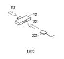
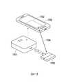
圖1示出無線電力傳輸器(WPT)101,所述無線電力傳輸器101可以是插接至電子裝置中以在不使用任何電力纜線的情況下將無線電力111傳輸至無線電力接收器(WPR)的裝置或模組。WPT 101將藉由導線或連接器102插接至電源112中。WPT 101亦可允許電子電源112控制WPT 101的電力及操作。WPT 101可在傳輸任何無線電力之前偵測是否存在可靠近的WPR。FIG. 1 shows a wireless power transmitter (WPT) 101, which may be plugged into an electronic device to transmit
圖2示出無線電力傳輸器(WPT)101的替代實施例。WPT 101可更包括電力插座201,電力插座201允許連接器202插接至其中。連接器202將自電源112轉送電力至另一裝置。FIG. 2 shows an alternative embodiment of a wireless power transmitter (WPT) 101. The WPT 101 may further include a
圖3示出WPT 301,WPT 301與通訊模組整合在一起、內建於通訊模組內、與通訊模組組合在一起或位於同一封裝。具有通訊模組的WPT 301可在自WPT 301至WPR的第一方向314上傳輸通訊訊號,且在自WPR至WPT 301的第二方向315上接收通訊訊號。WPT 301可藉由導線或連接器自電源311接收電力,並可將無線電力313傳輸至WPR。通訊訊號可含有資料312,所述資料312可由諸如行動電話或智慧型電話等電子裝置來處理。資料312可被調變至藉由導線或連接器傳輸的無線電力313的載波上。在一實施例中,「第一方向」為自WPT至WPR的方向,「第二方向」為自WPR至WPT的方向。WPT 301亦可支援其他通訊方向的通訊,例如將在本揭露的其他實施例中闡述的第三方向及第四方向。Figure 3 shows WPT 301. WPT 301 is integrated with the communication module, built in the communication module, combined with the communication module, or in the same package. The
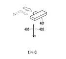
圖4示出WPT 401,若WPT 401含有資料處理器及混合器,則可將WPT 401的在第一方向上的通訊訊號402混合或乘載於無線電力403的載波之上。FIG. 4 shows the WPT 401. If the WPT 401 includes a data processor and a mixer, the
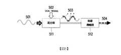
圖5示出將經調變的資料混合至無線地傳輸的電力訊號的載波中的實施方案。WPT可利用混合器電路511電性連接至無線傳輸器512。混合器電路511以載波501的形式接收電力(例如,自如圖1中所示的電源112),載波501混合經調變的資料502以形成乘載資料的經調變的電力訊號503。無線傳輸器512可在第一方向504上傳輸經調變的電力訊號503。若WPT含有資料調變器,則WPT亦可能夠調變未經調變的資料(例如數位訊號資料)。FIG. 5 shows an implementation of mixing modulated data into a carrier wave of a wirelessly transmitted power signal. The WPT can be electrically connected to the
圖6示出無線電力接收器(WPR)601,無線電力接收器601是可在無任何傳導體連接的情況下自WPT接收無線電力602並將電力提供至電性元件的裝置或模組。可藉由導線或連接器將所接收到的電力傳輸至另一電性元件603或另一裝置603。WPR 601亦可允許所連接的裝置603控制其電力及操作。與圖3的示例性實施例類似,WPR 601亦可與通訊模組整合在一起、內建於通訊模組內、與通訊模組組合在一起或位於同一封裝。FIG. 6 shows a wireless power receiver (WPR) 601. The
圖7說明根據本揭露的示例性實施例的與通訊模組整合在一起、構建至通訊模組內部中或與通訊模組組合的WPR。圖7示出自WPT接收無線電力701並將電力提供至電性元件704的WPR 706的實施例。WPR 706與通訊模組組合或整合在一起,所述通訊模組能夠在第一方向702上接收無線訊號且在第二方向703上傳輸無線訊號。自所述通訊模組傳輸而來或傳輸至所述通訊模組的資料705可由與WPR連接的電子裝置處理,或在電子裝置或通訊模組含有資料處理元件的情況下由通訊模組自身處理。通訊模組亦可支援在其他方向的通訊,諸如在本揭露的後半部分中闡述的「第三方向」及「第四方向」。FIG. 7 illustrates a WPR integrated with a communication module, built into the communication module, or combined with the communication module according to an exemplary embodiment of the present disclosure. FIG. 7 shows an embodiment of WPR 706 that receives
圖8示出WPR亦可接收經調變的無線電力801,其可自經調變的無線電力801獲得乘載於無線電力載波802之上的經調變的資料。WPR更含有電力資料分離器及資料處理器。可使用雙工器803自無線電力804分割出無線電力載波802所乘載的資料805,其中雙工器803包括低通濾波器(low pass filter,LPF)及帶通濾波器(bandpass filter,BPS)。低通濾波器用於自無線電力載波802提取無線電力804,且帶通濾波器用於自無線電力載波802提取資料805。8 shows that WPR can also receive modulated
上述WPR可與電子裝置整合或連接以為所述電子裝置的元件提供電力。圖9說明電子鎖901,電子鎖901可以是獨立裝置或可插接模組且將連接至外部WPR 913。電子鎖901可僅由WPR 913單獨地供電。電子鎖901可包括通訊模組902,通訊模組902可以是用於自電子裝置接收通訊訊號(例如,「第三方向」911)且用於將通訊訊號傳輸至電子裝置(例如,「第四方向」912)的無線收發器。電子裝置可以是例如已安裝APP以與電子鎖901互動的行動電話、平板電腦或筆記型電腦。若WPT亦促成在第三方向及在第四方向的通訊,則電子鎖亦可與WPT進行通訊。The above-mentioned WPR can be integrated with or connected to an electronic device to provide power to the components of the electronic device. FIG. 9 illustrates an
圖10說明電子鎖1001的另一實施例,電子鎖1001與圖9所示電子鎖901極為類似,但電子鎖1001含有整合式或內建式WPR 1002。FIG. 10 illustrates another embodiment of the
通常,無論WPR與電子鎖是整合在一起還是分開於不同的位置中,WPR與電子鎖皆可經由連接線或連接器彼此連接。在接收到無線電力之後,無線電力的接收使得WPR觸發具備或不具備主動電源(諸如電池、插接至壁裝插座中的電力供應器(power supply))的電子鎖的功能。換言之,電子鎖可不依賴於先前已儲存起能量供應的任何電源(例如電池)或來自壁裝插座的電源。電子鎖可僅依賴於WPR來實現其運作。WPR亦可以是觸發電子鎖的上電運作或斷電停止運作的頭源。Generally, no matter whether the WPR and the electronic lock are integrated or separated in different positions, the WPR and the electronic lock can be connected to each other through a connecting wire or a connector. After receiving the wireless power, the reception of the wireless power causes the WPR to trigger the function of an electronic lock with or without an active power source (such as a battery, a power supply plugged into a wall socket). In other words, the electronic lock does not depend on any power source (such as a battery) that has previously stored energy supply or power from a wall outlet. The electronic lock can only rely on WPR to realize its operation. WPR can also be the source that triggers the power-on operation or power-off of the electronic lock to stop the operation.
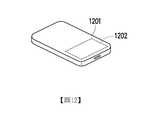
圖11說明連接至WPT的電源1101的實施例。所述電源可以是例如電力供應器或電力產生器、電力配接器、電池或行動電子裝置,諸如行動電話、平板電腦、筆記型電腦等。電源1101可經由導線或連接器連接至WPT。根據替代實施例,如圖12中所示,電源1201可具有內建式或整合式WPT 1202。Figure 11 illustrates an embodiment of a
圖13說明用作電子鎖的控制器的電子裝置1301的實施例。電子裝置1301可做為控制電子鎖(例如901)的操作的控制器,且電子裝置1301可以是含有無線收發器的行動電話,所述無線收發器藉由應用軟體(APP)與電子鎖(例如901)進行通訊。裝置1301可在第三方向1302上及在第四方向1303上進行通訊。在一實施例中,「第三方向」(例如1302)為自電子裝置(例如1301)至電子鎖(例如901)的方向,「第四方向」(例如1303)為自電子鎖(例如901)至電子裝置(例如1301)的方向。FIG. 13 illustrates an embodiment of an
通常,電子裝置將設置有WPT且電子鎖將設置有WPR,且在WPT或WPR亦含有收發器的情況下,電子裝置的收發器可藉由所述WPT及WPR進行通訊。例如,如圖13中所示且在電子裝置是行動電話的情況下,所述行動電話可用作在外部連接至行動電話的WPT 1304的電源,其中所述行動電話則可控制WPT的電力及操作。Generally, the electronic device will be provided with WPT and the electronic lock will be provided with WPR, and when the WPT or WPR also contains a transceiver, the transceiver of the electronic device can communicate through the WPT and WPR. For example, as shown in FIG. 13 and in the case where the electronic device is a mobile phone, the mobile phone can be used as a power source for the
圖14說明用作電子鎖的控制器的電子裝置1401的另一實施例。與圖13所示實施例類似,電子裝置1401可以是含有無線收發器的行動電話,所述無線收發器用於在第三方向1402上及在第四方向1403上進行通訊。電子裝置1401含有整合式WPT模組,所述整合式WPT模組是如圖14中所示的內建式或嵌入式WPT模組。若WPT模組1404含有收發器,則電子裝置1401亦可控制WPT模組1404的收發器將資料傳輸至WPT模組1404或自WPT模組1404接收資料。FIG. 14 illustrates another embodiment of an
圖15示出電子裝置1502與電子鎖1501之間分別使用外部WPT 1503及外部WPR 1504進行互動的實施例。在此實施例中,假定電子裝置1502是將電力提供至外部WPT 1503的行動電話。外部WPT 1503將向插接至電子鎖1501中的外部WPR 1504提供無線電力1505。在WPR 1504接收到足夠的無線電力1505之後,WPR 1504將能夠提供電子鎖1501實現其功能所需的電力。電子裝置1502亦可將經調變的資料傳達至WPT 1503與WPR 1504之間的無線電力1505上。電子鎖1501及電子裝置1502中的每一者可包括支援在第三方向1506上及在第四方向1507上的通訊的收發器。FIG. 15 shows an embodiment in which an
可藉由首先檢查並啟用電子裝置1502的通訊功能來使電子裝置1502與電子鎖1501互動,且檢查並啟用通訊功能可包括在電子裝置1502的通訊功能尚未被啟用的情況下檢查並啟用必要的硬體及/或軟體以能夠與電子鎖1501進行通訊。電子裝置可藉由APP或隨插即用功能啟用並控制WPT 1503。WPT 1503可偵測WPR的存在。若不斷靠近的WPT 1503已偵測到WPR 1504,則WPT 1503可允許將無線電力1505自WPT 1503傳輸至WPR 1504。或者,若WPT 1503由電子裝置1502控制,則當WPT 1503靠近並偵測到WPR 1504時,WPT 1503將向電子裝置1502發送關於所偵測到的WPR 1504的訊號。然後,電子裝置1502可將其電力引導至WPT 1503裝置以供進行無線傳輸。另一方面,電子鎖1501被配置成當WPR 1504接收到特定瓦特數範圍內的無線電力時上電運作,並可單獨地或與另一電源(諸如內部電池)結合地使用來自WPR 1504的無線電力作為其運作電力。在電子鎖1501被上電運作之後,電子鎖1501就可啟用其通訊功能(包括硬體及/或軟體),且然後與電子裝置1502進行通訊。The
圖16示出電子裝置1602與電子鎖1601之間分別使用外部WPT 1604及內部整合式WPR進行互動的實施例。在此實施例中,假定電子裝置1602是向外部WPT 1604提供電力的行動電話。外部WPT 1604將向插接至電子鎖1601中的內部整合式WPR模組1605提供無線電力1603。在WPR模組1605接收到足夠的無線電力1603之後,WPR模組1605將能夠提供電子鎖1601實現其功能所需的電力。其餘操作與圖15所示實施例類似。FIG. 16 shows an embodiment in which an
圖17示出電子裝置1702與電子鎖1701之間分別使用內部整合式WPT及外部WPR 1705進行互動的實施例。在此實施例中,假定電子裝置1702是向內部整合式WPT模組1703提供電力的行動電話。WPT模組1703將向插接至電子鎖1701中的外部WPR 1705提供無線電力1704。在WPR 1705接收到足夠的無線電力1704之後,WPR 1705將能夠提供電子鎖1701實現其功能所需的電力。其餘操作與圖15所示實施例類似。FIG. 17 shows an embodiment in which an internal integrated WPT and an
圖18示出電子裝置1802與電子鎖1801之間分別使用內部整合式WPT及內部整合式WPR進行互動的實施例。在此實施例中,假定電子裝置1802是向內部整合式WPT模組1803提供電力的行動電話。WPT模組1803將向插接至電子鎖1801中的內部整合式WPR 1805提供無線電力1804。在WPR 1805接收到足夠的無線電力1804之後,WPR 1805將能夠提供電子鎖1801實現其功能所需的電力。其餘操作與圖15所示實施例類似。FIG. 18 shows an embodiment in which an internal integrated WPT and an internal integrated WPR are used to interact between the
圖19示出電子裝置、包括內部整合式WPT模組的電源及包括內部整合式WPR模組的電子鎖三者之間進行互動的實施例。如圖19中所示,電源1902包括向WPR模組1905提供無線電力1904的內部整合式WPT模組1903。WPR模組1905整合於電子鎖1901內部且向電子鎖1901提供電力。可以是行動電話的電子裝置1911可使用其收發器來控制電子鎖1901,諸如藉由APP來將電子鎖1901上鎖或解鎖。因此,電子裝置1911的使用者可使用已安裝的APP,以使用收發器在第三方向1906及第四方向1907上傳輸並接收通訊訊號來控制電子鎖1901。FIG. 19 shows an embodiment of the interaction between an electronic device, a power supply including an internally integrated WPT module, and an electronic lock including an internally integrated WPR module. As shown in FIG. 19, the
此外,在此實施例中,電子裝置1911可在通訊功能尚未被啟用的情況下檢查並啟用其通訊功能(包括硬體及/或軟體),以能夠與電子鎖1901進行通訊。可藉由電源1902上的按鈕或開關啟用電源1902中的WPT模組1903的功能。一旦已啟用了WPT模組1903,則WPT模組1903將偵測WPR模組1905。若當WPT模組1903與WPR模組1905彼此靠近時,WPT模組1903偵測到WPR模組1905,則WPT模組1903將自電源1902引導電力,以將無線電力1904傳輸至WPR模組1905。另一方面,電子鎖1901被配置成當WPR模組1905接收到足夠的電力或接收到處於特定電力範圍內的電力以為電子鎖1901的功能供電時上電運作。在電子鎖1901已上電運作之後,電子鎖1901可啟用其包括硬體及/或軟體的通訊功能並與電子裝置1911進行通訊。或者,電子鎖1901亦可以是具有圖9中所示外部WPR的電子鎖901,且電源1902亦可以是具有圖11中所示外部WPT的電源1101。In addition, in this embodiment, the
圖20示出具有外部WPR的電子鎖2001與具有外部WPT的電子裝置2002(諸如,行動電話)之間的互動,其中所述外部WPR與通訊模組整合或組合在一起,而所述外部WPT與通訊模組整合或組合在一起。類似地,電子鎖2001亦連接至外部WPR裝置,其中所述外部WPR裝置亦與通訊模組整合或組合在一起。可藉由安裝於電子裝置2002中的APP或隨插即用驅動器來控制WPT 2004,以實施WPT 2004的功能。WPT 2004可試圖偵測WPR 2003。若WPT 2004與WPR 2003彼此靠近,則WPT 2004可偵測到WPR 2003。電子裝置2002或WPT 2004將允許電力自電子裝置2002引導至WPT 2004,從而以無線電力2005的形式傳輸至WPR 2003。20 shows the interaction between an
或者,若WPT 2004由電子裝置2002控制且當WPT 2004偵測到正在靠近的WPR 2003時,WPT 2004可將指示已偵測到WPR的訊號發送至電子裝置2002。接下來,電子裝置2002可將其電力及資料鏈路引導至WPT裝置2004,WPT裝置2004已與通訊模組整合或組合在一起以實現無線電力傳輸及通訊。另一方面,電子鎖2001被配置成當WPR 2003已接收到處於特定電力範圍內的足以啟用WPR 2003的電力以單獨地或與電子鎖2001的內部電池結合來提供電力以支援電子鎖2001的操作時接通。在電子鎖2001的操作已接通之後,電子鎖2001將啟用與WPR 2003的通訊模組的資料鏈路,以建立電子裝置2002與電子鎖2001之間的端對端資料鏈路。Alternatively, if the
若WPT 2004的通訊模組能夠在第三方向上或在第四方向上進行通訊,則WPT 2004可直接與電子鎖2001進行通訊。若WPR 2003的通訊模組能夠在第三方向上及在第四方向上進行通訊,則WPR 2003可直接與電子裝置2002進行通訊。在WPT 2004與WPR 2003彼此可在第一方向2006及第二方向2007上進行通訊的情況下,可將第一方向2006上的通訊混合或乘載於WPT 2004與WPR 2003之間的無線電力2005之上。If the
圖21示出電子鎖2101與電子裝置2102之間的互動。電子鎖2101具有包括通訊模組的內部整合式WPR 2104,且電子裝置2102可以是具有外部WPT 2103的行動電話,其中外部WPT 2103亦包括通訊模組。當WPT 2103在WPT 2103靠近WPR 2104(或反之亦然)的情況下偵測到WPR 2104的存在時,WPT 2103將無線電力2105傳輸至WPR 2104。WPT 2103的通訊模組及WPR 2104的通訊模組將支援WPT 2103與WPR 2104之間在第一方向2106上及在第二方向2107上進行的無線通訊。圖21的操作原理與圖20的操作原理類似。FIG. 21 shows the interaction between the
圖22示出具有外部WPR 2203的電子鎖2201與具有外部WPT 2204的電子裝置2202(諸如,行動電話)之間的互動的不同實施例,其中所述外部WPR 2203與通訊模組整合或組合在一起,而所述外部WPT 2204與通訊模組整合或組合在一起。在此實施例中,無線電力2205可乘載在第一方向上傳輸的經調變的資料,而WPT 2204的通訊模組及WPR 2203的通訊模組用於實現第二方向2206的資料傳輸。如此一來,行動電話可藉由在第一方向上經由無線電力2205發送資料且在第二方向2206上藉由WPR的通訊模組及WPT的通訊模組接收資料來控制電子鎖。Figure 22 shows different embodiments of the interaction between an
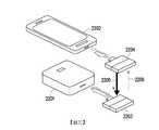
圖23示出具有外部WPR 2303的電子鎖2301與具有內部整合式WPT 2306的電子裝置2302(諸如,行動電話)之間的互動,其中所述外部WPR 2303與通訊模組整合或組合在一起,而所述內部整合式WPT 2306與通訊模組整合或組合在一起。可藉由安裝於電子裝置2302內的APP或藉由隨插即用驅動器控制WPT 2306來啟用WPT 2306的功能。當WPT 2306與WPR 2303彼此靠近時,WPT 2306可偵測WPR 2303。若WPT 2306偵測到WPR 2303,則電子裝置2302可允許自WPT 2306引導的電力無線地傳輸至WPR 2303。或者,若WPT 2306由電子裝置2302控制且當WPT 2306偵測到WPR 2303時,則WPT 2306可將指示已偵測到WPR 2303的訊號發送至電子裝置2302,然後電子裝置2302將引導其電力及資料鏈路至WPT模組2306以實現無線電力傳輸及通訊。另一方面,電子鎖2301被配置成當外部WPR 2303已接收到特定電力範圍的足夠的電力時接通,且可使用來自WPR 2303或另一電源(諸如,內部電池)的電力作為其運作電力。在電子鎖2301已接通之後,所述電子鎖2301可啟用與WPR 2303的通訊模組的資料鏈路,以建立電子鎖2301與電子裝置2302之間的端對端資料鏈路。若WPT 2306的通訊模組能夠在第三方向2310上及在第四方向2311上進行通訊,則WPT 2306將能夠直接與電子鎖2301進行通訊。若WPR 2303的通訊模組能夠在第三方向2310上及在第四方向2311上進行通訊,則WPR 2303將能夠直接與電子裝置2302進行通訊。或者,可將第一方向上的通訊混合或乘載於自WPT 2306至WPR 2303的無線電力2304之上。若僅需要在第一方向上進行通訊(單向通訊),則可不實施在第二方向上的通訊。Figure 23 shows the interaction between an
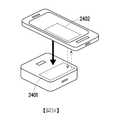
圖24示出具有內部整合式WPR的電子鎖與具有內部整合式WPT的電子裝置(諸如,行動電話)之間的互動,其中所述內部整合式WPR與通訊模組整合或組合在一起,而所述內部整合式WPT與通訊模組整合或組合在一起。此示例性實施例與圖18所示示例性實施例類似,但內部整合式WPT模組2402亦包括通訊模組,且內部整合式WPR模組2401亦包括通訊模組。WPT模組2402的通訊模組及WPR模組2401的通訊模組可促成在第一方向上及在第二方向上的通訊,且將無線電力自WPT模組2402傳輸至WPR模組2401。Figure 24 shows the interaction between an electronic lock with an internally integrated WPR and an electronic device (such as a mobile phone) with an internally integrated WPT, where the internally integrated WPR is integrated or combined with a communication module, and The internally integrated WPT is integrated or combined with the communication module. This exemplary embodiment is similar to the exemplary embodiment shown in FIG. 18, but the internally integrated
圖25示出具有內部整合式WPR的電子鎖與具有內部整合式WPT的電子裝置(諸如,行動電話)之間的互動的另一實施例,其中所述內部整合式WPR與通訊模組整合或組合在一起,而所述內部整合式WPT與通訊模組整合或組合在一起。在此實施例中,操作原理與圖24類似,但藉由以自WPT傳輸至WPR的無線電力乘載經調變的資料來實施在第一方向2501上的通訊,且藉由使WPR的通訊模組將資料傳輸至WPT的通訊模組來實施在第二方向2502上的通訊。Figure 25 shows another embodiment of the interaction between an electronic lock with an internally integrated WPR and an electronic device (such as a mobile phone) with an internally integrated WPT, wherein the internally integrated WPR is integrated with the communication module or Combined together, and the internally integrated WPT and the communication module are integrated or combined together. In this embodiment, the operating principle is similar to that of FIG. 24, but the wireless power transmitted from WPT to WPR is used to carry the modulated data to implement communication in the
圖26示出具有外部WPR的電子鎖與具有外部WPT的電源之間的互動,其中所述外部WPR與通訊模組整合或組合在一起,而所述外部WPT與通訊模組整合或組合在一起。如圖26所示,WPT 2604及WPR 2603含有其自身的通訊模組及資料處理器,以使得WPT 2604及WPR 2603可與不具有任何控制器裝置的其他裝置建立資料通訊鏈路。一旦實現與電源2602的連接且電力可用,則可藉由隨插即用驅動器啟用WPT 2604。在當WPT 2604與WPR 2603彼此靠近且WPT 2604偵測到WPR 2603之後,WPT 2604可允許自電源2602引導電力以無線地傳輸至WPR 2603且建立在第一方向及第二方向上的通訊。另一方面,電子鎖2601被配置成當外部WPR裝置2603(或內建式WPR模組)接收到特定電力範圍內足夠的電力時接通,且可單獨地或與另一電源(諸如,內部電池)結合地使用來自WPR 2603的電力作為其運作電力。在建立電子鎖與WPR 2603的通訊模組之間的資料通訊鏈路之後,可建立WPT 2604的資料處理器與電子鎖裝置2601的資料處理器之間的端對端資料鏈路。或者,可將在第一方向2605上的資料通訊混合/乘載於自WPT 2604至WPR 2603的無線電力訊號之上。另外,若僅需要在第一方向2605上進行通訊(單向通訊),則可不實施在第二方向2606上的通訊。Figure 26 shows the interaction between an electronic lock with an external WPR and a power supply with an external WPT, where the external WPR is integrated or combined with the communication module, and the external WPT is integrated or combined with the communication module . As shown in Figure 26,
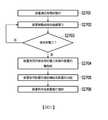
圖27說明根據本揭露的示例性實施例的操作電子鎖的方法。在步驟S2701中,假定電子鎖處於無電狀態中,在所述無電狀態下有效電源尚未給電子鎖通電,且電子鎖不擁有包括電池、電力供應器、電力線等在內的任何有效電源。在步驟S2702中,電子鎖被動地接收無線電力。在步驟S2703中,電子鎖判斷是否已接收到足以操作電子鎖功能的無線電力。若否,則重複步驟S2702。若是,則執行步驟S2704。在步驟S2704中,電子鎖使用所接收到的無線電力來操作電路板。在步驟S2705中,在啟動電路板之後,電子鎖啟用電子鎖的電路板的收發器的功能。在步驟S2706中,電子鎖的收發器將與另一電子裝置或與外部模組進行通訊。FIG. 27 illustrates a method of operating an electronic lock according to an exemplary embodiment of the present disclosure. In step S2701, it is assumed that the electronic lock is in a non-powered state. In the non-powered state, the effective power source has not energized the electronic lock, and the electronic lock does not have any effective power source including battery, power supply, power line, etc. In step S2702, the electronic lock passively receives wireless power. In step S2703, the electronic lock determines whether it has received sufficient wireless power to operate the electronic lock function. If not, step S2702 is repeated. If yes, step S2704 is executed. In step S2704, the electronic lock uses the received wireless power to operate the circuit board. In step S2705, after the circuit board is activated, the electronic lock activates the function of the transceiver of the circuit board of the electronic lock. In step S2706, the transceiver of the electronic lock will communicate with another electronic device or with an external module.
圖28說明操作電子鎖的方法,但此實施例未採取對電子鎖的連續供電。在步驟S2801中,電子鎖經由WPR被動地接收無線電力。在步驟S2802中,電子鎖判斷是否已接收到足以操作電子鎖的功能的無線電力。若否,則重複步驟S2801。若是,執行步驟S2803。在步驟S2803中,電子鎖使用所接收到的無線電力來操作電路板。此外,在步驟S2806,電子鎖判斷是否已接收到足以操作電子鎖的功能的無線電力。若否,則重複步驟S2801。若是,則執行步驟S2804。在步驟S2804中,在啟動電路板之後,電子鎖啟用電子鎖的電路板的收發器的功能。在步驟S2807中,電子鎖判斷是否已接收到足以操作電子鎖功能的無線電力。若否,則重複步驟S2801。若是,則執行步驟S2805。在步驟S2805中,電子鎖的收發器將與另一電子裝置或與外部模組進行通訊。FIG. 28 illustrates the method of operating the electronic lock, but this embodiment does not adopt continuous power supply to the electronic lock. In step S2801, the electronic lock passively receives wireless power via WPR. In step S2802, the electronic lock determines whether it has received wireless power sufficient to operate the function of the electronic lock. If not, step S2801 is repeated. If yes, go to step S2803. In step S2803, the electronic lock uses the received wireless power to operate the circuit board. In addition, in step S2806, the electronic lock determines whether it has received sufficient wireless power to operate the function of the electronic lock. If not, step S2801 is repeated. If yes, step S2804 is executed. In step S2804, after the circuit board is activated, the electronic lock activates the function of the transceiver of the circuit board of the electronic lock. In step S2807, the electronic lock determines whether it has received sufficient wireless power to operate the electronic lock function. If not, step S2801 is repeated. If yes, step S2805 is executed. In step S2805, the transceiver of the electronic lock will communicate with another electronic device or with an external module.
圖29說明根據本揭露的示例性實施例的從控制電子鎖的電子裝置角度操作電子鎖的方法。所述電子裝置可以是先前所述的任何行動電子裝置,並做為電子鎖的控制器。在步驟S2901中,電子裝置將偵測WPT的存在,所述WPT可以是外部連接式的或內部整合式的。在步驟S2902中,若已偵測到WPT,則將繼續進行步驟S2903。若尚未偵測到WPT,則將重複步驟S2901。在步驟S2903中,所述電子裝置將給WPT通電。在步驟S2904中,所述電子裝置將在WPT與WPR彼此靠近時判斷是否偵測到WPR。在步驟S2905中,若偵測到WPR,則將繼續進行步驟S2906。若尚未偵測到WPR,則將重複步驟S2904。在步驟S2906中,WPT將向所偵測到的WPR無線地傳輸電力。在步驟S2907中,所述電子裝置將與由WPR供電的電子鎖進行通訊。FIG. 29 illustrates a method of operating an electronic lock from the perspective of an electronic device that controls the electronic lock according to an exemplary embodiment of the present disclosure. The electronic device can be any of the mobile electronic devices described previously, and can be used as a controller of the electronic lock. In step S2901, the electronic device will detect the existence of WPT, and the WPT may be externally connected or internally integrated. In step S2902, if WPT has been detected, step S2903 will continue. If WPT has not been detected, step S2901 will be repeated. In step S2903, the electronic device will power on the WPT. In step S2904, the electronic device will determine whether WPR is detected when WPT and WPR are close to each other. In step S2905, if WPR is detected, step S2906 will continue. If WPR has not been detected, step S2904 will be repeated. In step S2906, WPT will wirelessly transmit power to the detected WPR. In step S2907, the electronic device will communicate with an electronic lock powered by WPR.
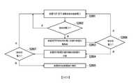
圖30說明從控制電子鎖的電子裝置的角度操作電子鎖的方法,但未採取連續供電。在步驟S3001中,所述電子裝置將偵測WPT的存在,所述WPT可以是外部連接式的或內部整合式的。在步驟S3002中,若偵測到WPT,則將繼續進行步驟S3003。若未偵測到WPT,則將重複步驟S3001。在步驟S3003中,所述電子裝置將給WPT通電。在步驟S3004中,所述電子裝置將在WPT與WPR彼此靠近時判斷是否偵測到WPR。在步驟S3005中,若已偵測到WPR,則將繼續進行步驟S3006。若未偵測到WPR,則將重複步驟S3004。在步驟S3006中,WPT將向所偵測到的WPR無線地傳輸電力。在步驟S3007中,電子裝置將判斷是否仍能偵測到WPR。若仍能偵測到WPR,則將繼續進行步驟S3008。若不再能偵測到WPR,則將重複步驟S3004。在步驟S3008中,所述電子裝置將與由WPR供電的電子鎖進行通訊。在步驟S3009中,所述電子裝置將偵測是否仍能偵測到WPR。若仍能偵測到WPR,則將重複步驟S3008。若不再能偵測到WPR,則將重複步驟S3004。FIG. 30 illustrates the method of operating the electronic lock from the perspective of the electronic device controlling the electronic lock, but the continuous power supply is not adopted. In step S3001, the electronic device will detect the presence of WPT, and the WPT may be externally connected or internally integrated. In step S3002, if WPT is detected, step S3003 will be continued. If no WPT is detected, step S3001 will be repeated. In step S3003, the electronic device will power on the WPT. In step S3004, the electronic device will determine whether WPR is detected when WPT and WPR are close to each other. In step S3005, if WPR has been detected, step S3006 will continue. If no WPR is detected, step S3004 will be repeated. In step S3006, WPT will wirelessly transmit power to the detected WPR. In step S3007, the electronic device will determine whether the WPR can still be detected. If the WPR can still be detected, step S3008 will continue. If WPR can no longer be detected, step S3004 will be repeated. In step S3008, the electronic device will communicate with an electronic lock powered by WPR. In step S3009, the electronic device will detect whether the WPR can still be detected. If WPR can still be detected, step S3008 will be repeated. If WPR can no longer be detected, step S3004 will be repeated.
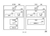
圖31是說明根據本揭露的另一示例性實施例的電子裝置與電子鎖系統的硬體方塊圖。電子鎖系統3100包括(但不限於)電子鎖3101及電子裝置3102。電子鎖3101包括:WPR 3111、電路板3112及致動器(actuator)3115,WPR 3111可接收無線電力以為電子鎖3101提供電力。電路板3112電性連接至WPR 3111且包括:第一無線收發器3114及控制器3113;第一無線收發器3114自電子裝置3102接收無線傳輸的上鎖命令或解鎖命令,控制器3113被配置成回應於接收到所述上鎖命令或所述解鎖命令而產生上鎖訊號或解鎖訊號。致動器3115電性連接至電路板3112且接收上鎖控制訊號以將鎖體機構元件3116上鎖或接收解鎖控制訊號以將鎖體機構元件3116解鎖。FIG. 31 is a hardware block diagram illustrating an electronic device and an electronic lock system according to another exemplary embodiment of the present disclosure. The
電子裝置3102包括(但不限於)電源、WPT 3121及電路板3122。WPT 3121連接至所述電源且被配置成提供無線電力。電路板3122包括處理器3123及第二無線收發器3124。處理器3123被配置成啟用WPT 3121以將無線電力傳輸至電子鎖3101的WPR 3111,且藉由第二無線收發器3124傳輸上鎖命令或解鎖命令以將電子鎖3101上鎖或解鎖。The
電子裝置3102更包括非暫時性儲存媒體(non-transitory storage medium)3125及使用者介面3127。非暫時性儲存媒體3125可以是非揮發性記憶體(non-volatile memory),諸如快閃驅動器、硬碟驅動器(hard disk drive,HDD)等。所述使用者介面可以是硬鍵盤、觸控螢幕、按鈕等。儲存媒體3125儲存APP 3126的程式設計碼,APP 3126將被載入至處理器3123中以實施與控制電子鎖3101相關聯的功能。藉由APP 3126,使用者可將上鎖命令或解鎖命令輸入至使用者介面3127中。在WPR 3111已接收到足夠的電力的情況下,當電子裝置3102靠近電子鎖3101時,使用者可藉由使用者介面3127輸入命令來將鎖體機構3116上鎖或解鎖。上鎖命令或解鎖命令可自第二無線收發器3124傳輸至第一無線收發器3114,或可作為經調變的資料自WPT 3121傳輸至WPR 3111。The
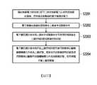
圖32說明根據本揭露的示例性實施例的操作電子鎖的方法。在步驟S3201中,電子鎖藉由無線電力接收器(WPR)接收無線電力以為電子鎖提供電力,所述電子鎖包括無線收發器、控制器及致動器。為接收到足以操作電子鎖的電力,WPR可應用可在智慧型電話、平板電腦、筆記型型電腦或電動車的無線充電系統中使用的一些無線電力輸送技術,諸如電感耦合(inductive coupling)、諧振(resonant)、電感耦合(inductive coupling)或電容耦合(capacitive coupling)。在步驟S3202中,電子鎖藉由無線收發器接收上鎖命令或解鎖命令。在步驟S3203中,電子鎖回應於接收到上鎖命令或解鎖命令而使用控制器產生上鎖控制訊號或解鎖控制訊號。在步驟S3204中,電子鎖回應於接收到所述上鎖控制訊號而使用致動器以驅動鎖體機構元件成為上鎖狀態,或接收所述解鎖控制訊號而使用致動器以驅動所述鎖體機構元件成為解鎖狀態,從而將電子鎖上鎖或解鎖。FIG. 32 illustrates a method of operating an electronic lock according to an exemplary embodiment of the present disclosure. In step S3201, the electronic lock receives wireless power through a wireless power receiver (WPR) to provide power to the electronic lock, and the electronic lock includes a wireless transceiver, a controller, and an actuator. In order to receive enough power to operate electronic locks, WPR can apply some wireless power transmission technologies that can be used in wireless charging systems for smart phones, tablets, notebooks, or electric vehicles, such as inductive coupling, Resonant, inductive coupling or capacitive coupling. In step S3202, the electronic lock receives a lock command or an unlock command through the wireless transceiver. In step S3203, the electronic lock uses the controller to generate a lock control signal or an unlock control signal in response to receiving a lock command or an unlock command. In step S3204, in response to receiving the lock control signal, the electronic lock uses an actuator to drive the lock body mechanism element into a locked state, or receives the unlock control signal and uses an actuator to drive the lock The body mechanism element becomes the unlocked state, thereby locking or unlocking the electronic lock.
鑒於前述說明,本揭露適用於電子鎖或具有所述電子鎖的電子裝置,以避免電池的需要或給電池充電的不便,以實現智慧鎖或電子裝置的無電池設計。此外,本揭露的電子鎖及電子裝置不需要電力線,因而免去了必須攜帶電力線的不便。In view of the foregoing description, the present disclosure is applicable to an electronic lock or an electronic device with the electronic lock to avoid the need for a battery or the inconvenience of charging the battery, so as to realize a battery-free design of the smart lock or the electronic device. In addition, the electronic lock and the electronic device disclosed in the present disclosure do not require a power cord, thus eliminating the inconvenience of having to carry a power cord.
本申請案所揭露的實施例的詳細說明中所使用的元件、動作或指令,除非明確闡述,否則皆不應被視為對本揭露絕對重要或必不可少。The elements, actions, or instructions used in the detailed description of the embodiments disclosed in this application should not be regarded as absolutely important or indispensable to this disclosure unless explicitly stated.
熟習此項技術者應明瞭,可在不背離本揭露的範疇或精神的情況下對所揭露實施例的結構做出各種潤飾及變化。鑒於前述內容,本揭露旨在涵蓋本揭露的潤飾及變化,只要所述潤飾及變化在以下申請專利範圍及其等效內容的範疇即可。Those familiar with the technology should understand that various modifications and changes can be made to the structure of the disclosed embodiment without departing from the scope or spirit of the present disclosure. In view of the foregoing, this disclosure intends to cover the modifications and changes of this disclosure, as long as the modifications and changes are within the scope of the following patent applications and their equivalent content.
101、301、401:無線電力傳輸器102:導線或連接器111、403、602、804、1505、1603、1704、1804、1904、2005、2105、2205、2304:無線電力112、311:電源201:電力插座202:連接器312、502、705、805:資料313、701:無線電力314、402、504、702、2006、2106、2501、2605:第一方向315、703、2007、2107、2206、2502、2606:第二方向501:載波503:電力訊號511:混合器電路512:無線傳輸器601、706、2003、3111:無線電力接收器603:另一電性元件或另一裝置/裝置704:電性元件801:經調變的無線電力802:無線電力載波803:雙工器901、1001、1501、1601、1701、1801、1901、2001、2101、2201、2301、3101:電子鎖902:通訊模組911、1302、1402、1506、1906、2310:第三方向912、1303、1403、1507、1907、2311:第四方向913、1504、1705、2203、2303:外部無線電力接收器/無線電力接收器1002:整合式或內建式無線電力接收器1101、1201、1902、2602:電源1202:內建式或整合式無線電力傳輸器1301、1401、1502、1602、1702、1802、1911、2002、2102、2202、2302、3102:電子裝置1304、2604、3121:無線電力傳輸器1404:無線電力傳輸器模組1503、2103、2204:外部無線電力傳輸器/無線電力傳輸器1604:外部無線電力傳輸器1605、2401:內部整合式無線電力接收器模組/無線電力接收器模組1703、1903、2402:內部整合式無線電力傳輸器模組/無線電力傳輸器模組1803:內部整合式無線電力傳輸器模組1805:內部整合式無線電力接收器/無線電力接收器1905:無線電力接收器模組2004:無線電力傳輸器/無線電力傳輸器裝置2104:內部整合式無線電力接收器2306:內部整合式無線電力傳輸器/無線電力傳輸器/無線電力傳輸器模組2601:電子鎖/電子鎖裝置2603:無線電力接收器/外部無線電力接收器裝置S2701、S2702、S2703、S2704、S2705、S2706、S2801、S2802、S2803、S2804、S2805、S2806、S2807、S2901、S2902、S2903、S2904、S2905、S2906、S2907、S3001、S3002、S3003、S3004、S3005、S3006、S3007、S3008、S3009、S3201、S3202、S3203、S3204:步驟3100:電子鎖系統3112、3122:電路板3113:控制器3114:第一無線收發器3115:致動器3116:鎖體機構元件/鎖體機構3123:處理器3124:第二無線收發器3125:非暫時性儲存媒體/儲存媒體3126:應用3127:使用者介面101, 301, 401: wireless power transmitter102: Wire or connector111, 403, 602, 804, 1505, 1603, 1704, 1804, 1904, 2005, 2105, 2205, 2304: wireless power112, 311: power supply201: Power socket202: Connector312, 502, 705, 805: data313, 701: wireless power314, 402, 504, 702, 2006, 2106, 2501, 2605: first direction315, 703, 2007, 2107, 2206, 2502, 2606: second direction501: Carrier503: Power Signal511: mixer circuit512: wireless transmitter601, 706, 2003, 3111: wireless power receiver603: Another electrical component or another device/device704: Electrical components801: Modulated wireless power802: wireless power carrier803: Duplexer901, 1001, 1501, 1601, 1701, 1801, 1901, 2001, 2101, 2201, 2301, 3101: electronic lock902: Communication module911, 1302, 1402, 1506, 1906, 2310: third-party direction912, 1303, 1403, 1507, 1907, 2311: fourth direction913, 1504, 1705, 2203, 2303: external wireless power receiver/wireless power receiver1002: Integrated or built-in wireless power receiver1101, 1201, 1902, 2602: power supply1202: Built-in or integrated wireless power transmitter1301, 1401, 1502, 1602, 1702, 1802, 1911, 2002, 2102, 2202, 2302, 3102: electronic devices1304, 2604, 3121: wireless power transmitter1404: wireless power transmitter module1503, 2103, 2204: External wireless power transmitter/wireless power transmitter1604: External wireless power transmitter1605, 2401: Internal integrated wireless power receiver module/wireless power receiver module1703, 1903, 2402: internal integrated wireless power transmitter module/wireless power transmitter module1803: Internal integrated wireless power transmitter module1805: Internal integrated wireless power receiver/wireless power receiver1905: wireless power receiver module2004: Wireless power transmitter/wireless power transmitter device2104: Internal integrated wireless power receiver2306: Internal integrated wireless power transmitter/wireless power transmitter/wireless power transmitter module2601: Electronic lock/electronic lock device2603: wireless power receiver/external wireless power receiver deviceS2701, S2702, S2703, S2704, S2705, S2706, S2801, S2802, S2803, S2804, S2805, S2806, S2807, S2901, S2902, S2903, S2904, S2905, S2906, S2907, S3001, S3002, S3003, S3004, S3005, S3006, S3007, S3008, S3009, S3201, S3202, S3203, S3204: steps3100: Electronic lock system3112, 3122: circuit board3113: Controller3114: The first wireless transceiver3115: Actuator3116: lock body mechanism components/lock body mechanism3123: processor3124: second wireless transceiver3125: Non-temporary storage media/storage media3126: application3127: User Interface
包括附圖以使得能進一步理解對本揭露,且附圖併入本說明書中且構成本說明書的一部分。圖式對本揭露的實施例加以說明,且與所述說明一起用於闡釋本揭露的原理。圖1說明根據本揭露的示例性實施例的無線電力傳輸器(wireless power transmitter,WPT)。圖2說明根據本揭露的示例性實施例的具有連接器的WPT,其中所述連接器用於轉送電力。圖3說明根據本揭露的示例性實施例的與通訊模組整合在一起、構建至通訊模組內部中或與通訊模組組合的WPT。圖4說明根據本揭露的示例性實施例的WPT,其中所述WPT的通訊訊號可混合於或乘載於無線電力的載波之上。圖5說明根據本揭露的示例性實施例的將經調變的資料混合至無線傳輸的電力訊號的載波中的實施方案。圖6說明根據本揭露的示例性實施例的無線電力接收器,其中所述無線電力接收器(wireless power receiver,WPR)可在無任何傳導體連接的情況下自WPT接收無線電力並將電力提供至電性元件。圖7說明根據本揭露的示例性實施例的與通訊模組整合在一起、構建至通訊模組內部中或與通訊模組組合WPR。圖8說明根據本揭露的示例性實施例的用於對來自無線電力載波的資料進行解調的電路。圖9說明根據本揭露的示例性實施例的將連接至WPR的電子鎖。圖10說明根據本揭露的示例性實施例的已與WPR整合在一起的電子鎖。圖11說明根據本揭露的示例性實施例的連接至外部WPT的電源的實施例。圖12說明根據本揭露的示例性實施例的連接至內部整合式WPT的電源的實施例。圖13說明根據本揭露的示例性實施例的具有外部WPT的電子裝置,其中所述電子裝置用作電子鎖的控制器。圖14說明根據本揭露的示例性實施例的具有整合式WPT的電子裝置,其中所述電子裝置用作電子鎖的控制器。圖15說明根據本揭露的示例性實施例的電子裝置與電子鎖之間的互動。圖16說明根據本揭露的示例性實施例的電子裝置與具有內建式WPR模組的電子鎖之間的互動。圖17說明根據本揭露的示例性實施例的在電子裝置與電子鎖之間分別使用內部整合式WPT及外部WPR進行的互動。圖18說明根據本揭露的示例性實施例的在電子裝置與電子鎖之間分別使用內部整合式WPT及內部整合式WPR進行的互動。圖19說明根據本揭露的示例性實施例的電子裝置、包括內部整合式WPT模組的電源及包括內部整合式WPR模組的電子鎖三者之間的互動。圖20說明根據本揭露的示例性實施例的電子鎖與電子裝置之間的互動,其中所述電子鎖具有與通訊模組整合或組合在一起的外部WPR,且所述電子裝置具有與通訊模組整合或組合在一起的外部WPT。圖21說明根據本揭露的示例性實施例的電子鎖與電子裝置之間的互動,其中所述電子鎖具有與通訊模組整合或組合在一起的外部WPR,且所述電子裝置具有與通訊模組整合或組合在一起的內部WPT。圖22說明圖20的替代示例性實施例。圖23說明根據本揭露的示例性實施例的電子鎖與電子裝置(諸如,行動電話)之間的互動,其中所述電子鎖具有與通訊模組整合或組合在一起的外部WPR,且所述電子裝置具有與通訊模組整合或組合在一起的內部整合式WPT。圖24說明根據本揭露的示例性實施例的電子鎖與電子裝置(諸如,行動電話)之間的互動,其中所述電子鎖具有與通訊模組整合或組合在一起的內部整合式WPR,且所述電子裝置具有與通訊模組整合或組合在一起的內部整合式WPT。圖25說明根據本揭露的示例性實施例的電子鎖與電子裝置(諸如,行動電話)之間的互動,其中所述電子鎖具有與通訊模組整合或組合在一起的內部整合式WPR,且所述電子裝置具有與通訊模組整合或組合在一起的內部整合式WPT。圖26說明根據本揭露的示例性實施例的電子鎖與電源之間的互動,其中所述電子鎖具有與通訊模組整合或組合在一起的外部WPR,且所述電源具有與通訊模組整合或組合在一起的外部WPT。圖27說明根據本揭露的示例性實施例的操作電子鎖的方法。圖28說明根據本揭露的另一示例性實施例在不採取連續供電的情況下操作電子鎖的方法。圖29說明根據本揭露的示例性實施例從控制電子鎖的電子裝置的角度操作所述電子鎖的方法。圖30說明根據本揭露的另一示例性實施例在不採取連續供電的情況下從控制電子鎖的電子裝置的角度來操作所述電子鎖的方法。圖31是說明根據本揭露的另一示例性實施例的電子裝置及電子鎖系統的硬體方塊圖。圖32說明根據本揭露的另一示例性實施例的操作電子鎖的方法。The drawings are included to enable a further understanding of the present disclosure, and the drawings are incorporated into this specification and constitute a part of this specification. The drawings illustrate the embodiments of the present disclosure, and together with the description are used to explain the principles of the present disclosure.FIG. 1 illustrates a wireless power transmitter (WPT) according to an exemplary embodiment of the present disclosure.Figure 2 illustrates a WPT with a connector according to an exemplary embodiment of the present disclosure, wherein the connector is used to transfer power.FIG. 3 illustrates a WPT integrated with a communication module, built into the communication module, or combined with the communication module according to an exemplary embodiment of the present disclosure.FIG. 4 illustrates a WPT according to an exemplary embodiment of the present disclosure, wherein the communication signal of the WPT can be mixed or carried on a wireless power carrier.FIG. 5 illustrates an implementation of mixing modulated data into a carrier wave of a wirelessly transmitted power signal according to an exemplary embodiment of the present disclosure.6 illustrates a wireless power receiver according to an exemplary embodiment of the present disclosure, wherein the wireless power receiver (wireless power receiver, WPR) can receive wireless power from WPT and provide power without any conductor connection To electrical components.FIG. 7 illustrates a WPR integrated with a communication module, built into the communication module, or combined with the communication module according to an exemplary embodiment of the present disclosure.FIG. 8 illustrates a circuit for demodulating data from a wireless power carrier according to an exemplary embodiment of the present disclosure.Fig. 9 illustrates an electronic lock to be connected to a WPR according to an exemplary embodiment of the present disclosure.FIG. 10 illustrates an electronic lock integrated with WPR according to an exemplary embodiment of the present disclosure.FIG. 11 illustrates an embodiment of a power supply connected to an external WPT according to an exemplary embodiment of the present disclosure.FIG. 12 illustrates an embodiment of a power supply connected to an internal integrated WPT according to an exemplary embodiment of the present disclosure.FIG. 13 illustrates an electronic device with an external WPT according to an exemplary embodiment of the present disclosure, wherein the electronic device is used as a controller of an electronic lock.FIG. 14 illustrates an electronic device with an integrated WPT according to an exemplary embodiment of the present disclosure, wherein the electronic device is used as a controller of an electronic lock.FIG. 15 illustrates the interaction between an electronic device and an electronic lock according to an exemplary embodiment of the present disclosure.FIG. 16 illustrates the interaction between an electronic device according to an exemplary embodiment of the present disclosure and an electronic lock with a built-in WPR module.FIG. 17 illustrates the interaction between an electronic device and an electronic lock using an internal integrated WPT and an external WPR, respectively, according to an exemplary embodiment of the present disclosure.FIG. 18 illustrates the interaction between an electronic device and an electronic lock using an internal integrated WPT and an internal integrated WPR, respectively, according to an exemplary embodiment of the present disclosure.FIG. 19 illustrates the interaction between the electronic device, the power supply including the internal integrated WPT module, and the electronic lock including the internal integrated WPR module according to an exemplary embodiment of the present disclosure.20 illustrates the interaction between an electronic lock and an electronic device according to an exemplary embodiment of the present disclosure, wherein the electronic lock has an external WPR integrated or combined with a communication module, and the electronic device has an external WPR integrated with or combined with a communication module. External WPT integrated or grouped together.21 illustrates the interaction between an electronic lock and an electronic device according to an exemplary embodiment of the present disclosure, wherein the electronic lock has an external WPR integrated or combined with a communication module, and the electronic device has a communication module Group integrated or grouped together internal WPT.FIG. 22 illustrates an alternative exemplary embodiment of FIG. 20. FIG.FIG. 23 illustrates the interaction between an electronic lock and an electronic device (such as a mobile phone) according to an exemplary embodiment of the present disclosure, wherein the electronic lock has an external WPR integrated or combined with a communication module, and the The electronic device has an internal integrated WPT integrated or combined with the communication module.24 illustrates the interaction between an electronic lock and an electronic device (such as a mobile phone) according to an exemplary embodiment of the present disclosure, wherein the electronic lock has an internal integrated WPR integrated or combined with a communication module, and The electronic device has an internal integrated WPT integrated or combined with a communication module.FIG. 25 illustrates the interaction between an electronic lock and an electronic device (such as a mobile phone) according to an exemplary embodiment of the present disclosure, wherein the electronic lock has an internal integrated WPR integrated or combined with a communication module, and The electronic device has an internal integrated WPT integrated or combined with a communication module.26 illustrates the interaction between an electronic lock and a power supply according to an exemplary embodiment of the present disclosure, wherein the electronic lock has an external WPR integrated or combined with a communication module, and the power supply has an integration with the communication module Or an external WPT combined together.FIG. 27 illustrates a method of operating an electronic lock according to an exemplary embodiment of the present disclosure.FIG. 28 illustrates a method of operating an electronic lock without using continuous power supply according to another exemplary embodiment of the present disclosure.FIG. 29 illustrates a method of operating the electronic lock from the perspective of an electronic device that controls the electronic lock according to an exemplary embodiment of the present disclosure.FIG. 30 illustrates a method of operating the electronic lock from the perspective of the electronic device controlling the electronic lock without using continuous power supply according to another exemplary embodiment of the present disclosure.FIG. 31 is a hardware block diagram illustrating an electronic device and an electronic lock system according to another exemplary embodiment of the present disclosure.FIG. 32 illustrates a method of operating an electronic lock according to another exemplary embodiment of the present disclosure.
1701:電子鎖1701: Electronic lock
1702:電子裝置1702: electronic device
1703:內部整合式無線電力傳輸器模組/無線電力傳輸器模組1703: Internal integrated wireless power transmitter module/wireless power transmitter module
1704:無線電力1704: wireless power
1705:外部無線電力接收器/無線電力接收器1705: External wireless power receiver/wireless power receiver
Claims (33)
Translated fromChineseApplications Claiming Priority (2)
| Application Number | Priority Date | Filing Date | Title |
|---|---|---|---|
| US201862727003P | 2018-09-05 | 2018-09-05 | |
| US62/727,003 | 2018-09-05 |
Publications (2)
| Publication Number | Publication Date |
|---|---|
| TW202012764A TW202012764A (en) | 2020-04-01 |
| TWI744689Btrue TWI744689B (en) | 2021-11-01 |
Family
ID=69642128
Family Applications (1)
| Application Number | Title | Priority Date | Filing Date |
|---|---|---|---|
| TW108132087ATWI744689B (en) | 2018-09-05 | 2019-09-05 | Electronic lock without active power source, electronic device having the electronic lock, and method of operating the electronic lock thereof |
Country Status (2)
| Country | Link |
|---|---|
| US (1) | US11643842B2 (en) |
| TW (1) | TWI744689B (en) |
Families Citing this family (3)
| Publication number | Priority date | Publication date | Assignee | Title |
|---|---|---|---|---|
| US11462062B1 (en)* | 2019-07-19 | 2022-10-04 | Alarm.Com Incorporated | Power connection for smart lock devices |
| US11282313B2 (en)* | 2019-12-31 | 2022-03-22 | 3M Innovative Properties Company | Smart locking systems and methods |
| WO2025184792A1 (en)* | 2024-03-05 | 2025-09-12 | Nanjing Easthouse Electrical Co., Ltd. | Electronic locks having wireless couplers and methods of using the same |
Citations (5)
| Publication number | Priority date | Publication date | Assignee | Title |
|---|---|---|---|---|
| CN102306413A (en)* | 2011-09-15 | 2012-01-04 | 吴斐 | electronic door lock |
| TW201509055A (en)* | 2013-05-16 | 2015-03-01 | Microchip Tech Inc | Wireless door lock power transfer system having communications capabilities |
| JP2016160734A (en)* | 2015-03-05 | 2016-09-05 | 美和ロック株式会社 | Door power generation device and electric lock system including the same |
| CN206140448U (en)* | 2016-03-10 | 2017-05-03 | 苏州宝时得电动工具有限公司 | Intelligent toolbox |
| JP2017172314A (en)* | 2016-03-17 | 2017-09-28 | 日本電産サンキョー株式会社 | Electric lock system |
Family Cites Families (25)
| Publication number | Priority date | Publication date | Assignee | Title |
|---|---|---|---|---|
| US6057657A (en) | 1998-07-02 | 2000-05-02 | Shimano, Inc. | Magnetically operated bicycle antitheft device |
| US7346331B2 (en)* | 2001-09-30 | 2008-03-18 | Harrow Products, Llc | Power management for locking system |
| US7289764B2 (en)* | 2001-09-30 | 2007-10-30 | Harrow Products, Llc | Cardholder interface for an access control system |
| US7747286B2 (en)* | 2004-01-20 | 2010-06-29 | Harrow Products Llc | Wireless access control system with energy-saving piezo-electric locking |
| US8864205B2 (en)* | 2006-06-28 | 2014-10-21 | Stryker Corporation | Patient support with wireless data and/or energy transfer |
| US9337902B2 (en)* | 2008-03-17 | 2016-05-10 | Powermat Technologies Ltd. | System and method for providing wireless power transfer functionality to an electrical device |
| CN101545337A (en) | 2008-03-28 | 2009-09-30 | 林岱右 | Electricity-free electric lock piece and control method thereof |
| JP4661900B2 (en) | 2008-04-17 | 2011-03-30 | ソニー株式会社 | Wireless communication apparatus, power supply method, program, and wireless communication system |
| CA2729544C (en)* | 2008-06-27 | 2016-09-20 | Schlage Lock Company | Electronic door lock with modular components |
| US8111042B2 (en) | 2008-08-05 | 2012-02-07 | Broadcom Corporation | Integrated wireless resonant power charging and communication channel |
| US8928276B2 (en)* | 2008-09-27 | 2015-01-06 | Witricity Corporation | Integrated repeaters for cell phone applications |
| US8401595B2 (en) | 2008-12-08 | 2013-03-19 | Samsung Electronics Co., Ltd. | Method and system for integrated wireless power and data communication |
| CN102549625A (en)* | 2009-06-08 | 2012-07-04 | 哈罗产品有限公司 | Electronic door lock for reduced power consumption |
| US8686685B2 (en) | 2009-12-25 | 2014-04-01 | Golba, Llc | Secure apparatus for wirelessly transferring power and communicating with one or more slave devices |
| WO2011097274A1 (en)* | 2010-02-02 | 2011-08-11 | Snap-On Incorporated | Tool box locking mechanisms for remote activation |
| KR101688948B1 (en) | 2011-05-27 | 2016-12-22 | 엘지전자 주식회사 | Establishing a data communication connection using a wireless power transmission |
| US9094111B2 (en) | 2011-05-27 | 2015-07-28 | uBeam Inc. | Receiver transducer for wireless power transfer |
| CN102312617A (en) | 2011-09-15 | 2012-01-11 | 吴斐 | A non-power electronic lock and corresponding unlocking handset device |
| KR101807335B1 (en)* | 2012-10-19 | 2018-01-10 | 삼성전자주식회사 | Wireless power receiver and method for setting a sleep mode of the wireless power receiver in wireless power network |
| KR102142558B1 (en) | 2013-04-17 | 2020-08-07 | 인텔렉추얼디스커버리 주식회사 | Apparatus and method for transmitting wireless power |
| US8947530B1 (en)* | 2013-07-26 | 2015-02-03 | Joseph Frank Scalisi | Smart lock systems and methods |
| US9704316B2 (en) | 2013-09-10 | 2017-07-11 | Gregory Paul Kirkjan | Contactless electronic access control system |
| US10122415B2 (en) | 2014-12-27 | 2018-11-06 | Energous Corporation | Systems and methods for assigning a set of antennas of a wireless power transmitter to a wireless power receiver based on a location of the wireless power receiver |
| US10559971B2 (en) | 2015-04-10 | 2020-02-11 | Ossia Inc. | Wirelessly chargeable battery apparatus |
| US10033436B2 (en) | 2016-08-24 | 2018-07-24 | Cisco Technology, Inc. | Power over wireless energy recharge (POWER) |
- 2019
- 2019-09-05TWTW108132087Apatent/TWI744689B/enactive
- 2019-09-05USUS16/561,030patent/US11643842B2/enactiveActive
Patent Citations (5)
| Publication number | Priority date | Publication date | Assignee | Title |
|---|---|---|---|---|
| CN102306413A (en)* | 2011-09-15 | 2012-01-04 | 吴斐 | electronic door lock |
| TW201509055A (en)* | 2013-05-16 | 2015-03-01 | Microchip Tech Inc | Wireless door lock power transfer system having communications capabilities |
| JP2016160734A (en)* | 2015-03-05 | 2016-09-05 | 美和ロック株式会社 | Door power generation device and electric lock system including the same |
| CN206140448U (en)* | 2016-03-10 | 2017-05-03 | 苏州宝时得电动工具有限公司 | Intelligent toolbox |
| JP2017172314A (en)* | 2016-03-17 | 2017-09-28 | 日本電産サンキョー株式会社 | Electric lock system |
Also Published As
| Publication number | Publication date |
|---|---|
| US11643842B2 (en) | 2023-05-09 |
| TW202012764A (en) | 2020-04-01 |
| US20200071957A1 (en) | 2020-03-05 |
Similar Documents
| Publication | Publication Date | Title |
|---|---|---|
| TWI744689B (en) | Electronic lock without active power source, electronic device having the electronic lock, and method of operating the electronic lock thereof | |
| CN107465240B (en) | A kind of intelligent movable power supplies and the method for carrying out usb data communication with it | |
| US10064040B2 (en) | System and method for secure pairing of bluetooth devices | |
| US7579809B2 (en) | Rechargeable wireless adapters | |
| US9661119B2 (en) | Method and device for the wireless control of a medical device | |
| US9843360B2 (en) | Method and system for use in configuring multiple near field antenna systems | |
| US10742050B2 (en) | Accessory communication over power pins | |
| TW201706862A (en) | Adapter devices for enhancing the functionality of other devices | |
| CN110247264B (en) | Connector and method for controlling charging by using connector | |
| JP7430626B2 (en) | Extended charging availability after vehicle ignition off | |
| CN205427859U (en) | Portable storage device | |
| US12379891B2 (en) | Wireless conferencing system and collaboration method thereof | |
| CN211152101U (en) | Wireless screen transmission equipment and interaction system | |
| CN105867240B (en) | A separate intelligent control system and its setting method | |
| CN212927389U (en) | Thing allies oneself with intelligent lock | |
| CN101521340B (en) | Dual Power Outlet Group Device with Remote Power Control | |
| KR100675841B1 (en) | Power Management Method in Wireless Universal Serial Bus Devices and Wireless Universal Serial Bus Devices | |
| WO2013189913A1 (en) | Peripheral device for converting and transmitting digital data via an audio connector | |
| WO2015186999A1 (en) | System and method for secured power source | |
| CN221529192U (en) | Multifunctional mobile memory | |
| CA2140261C (en) | Modem for communication with enclosed electronic equipment | |
| CN212302468U (en) | Serial communication interface equipment based on android system | |
| CN116795177A (en) | Anti-lost docking station and positioning method thereof | |
| KR102025728B1 (en) | Wireless data stroage device and near wireless communication terminal device | |
| CN105245259A (en) | Bluetooth switching device and security authentication system |