TWI742136B - Electrical connector assembly - Google Patents
Electrical connector assemblyDownload PDFInfo
- Publication number
- TWI742136B TWI742136BTW106127705ATW106127705ATWI742136BTW I742136 BTWI742136 BTW I742136BTW 106127705 ATW106127705 ATW 106127705ATW 106127705 ATW106127705 ATW 106127705ATW I742136 BTWI742136 BTW I742136B
- Authority
- TW
- Taiwan
- Prior art keywords
- module
- pressing
- electrical connector
- shift lever
- lever
- Prior art date
Links
- 239000013307optical fiberSubstances0.000claimsabstractdescription21
- 230000003287optical effectEffects0.000claimsabstractdescription10
- 230000005693optoelectronicsEffects0.000claimsdescription19
- 210000005069earsAnatomy0.000claimsdescription3
- 238000005452bendingMethods0.000claimsdescription2
- 230000000994depressogenic effectEffects0.000abstract1
- 238000000465mouldingMethods0.000abstract1
- NJPPVKZQTLUDBO-UHFFFAOYSA-NnovaluronChemical compoundC1=C(Cl)C(OC(F)(F)C(OC(F)(F)F)F)=CC=C1NC(=O)NC(=O)C1=C(F)C=CC=C1FNJPPVKZQTLUDBO-UHFFFAOYSA-N0.000description2
- 230000005540biological transmissionEffects0.000description1
- 230000000694effectsEffects0.000description1
- 238000011900installation processMethods0.000description1
- 230000002452interceptive effectEffects0.000description1
- 238000000034methodMethods0.000description1
- 238000012986modificationMethods0.000description1
- 230000004048modificationEffects0.000description1
Images


Classifications
- G—PHYSICS
- G02—OPTICS
- G02B—OPTICAL ELEMENTS, SYSTEMS OR APPARATUS
- G02B6/00—Light guides; Structural details of arrangements comprising light guides and other optical elements, e.g. couplings
- G02B6/24—Coupling light guides
- G02B6/42—Coupling light guides with opto-electronic elements
- G02B6/4201—Packages, e.g. shape, construction, internal or external details
- G02B6/4274—Electrical aspects
- G02B6/4284—Electrical aspects of optical modules with disconnectable electrical connectors
- H—ELECTRICITY
- H01—ELECTRIC ELEMENTS
- H01R—ELECTRICALLY-CONDUCTIVE CONNECTIONS; STRUCTURAL ASSOCIATIONS OF A PLURALITY OF MUTUALLY-INSULATED ELECTRICAL CONNECTING ELEMENTS; COUPLING DEVICES; CURRENT COLLECTORS
- H01R13/00—Details of coupling devices of the kinds covered by groups H01R12/70 or H01R24/00 - H01R33/00
- H01R13/62—Means for facilitating engagement or disengagement of coupling parts or for holding them in engagement
- H01R13/629—Additional means for facilitating engagement or disengagement of coupling parts, e.g. aligning or guiding means, levers, gas pressure electrical locking indicators, manufacturing tolerances
- G—PHYSICS
- G02—OPTICS
- G02B—OPTICAL ELEMENTS, SYSTEMS OR APPARATUS
- G02B6/00—Light guides; Structural details of arrangements comprising light guides and other optical elements, e.g. couplings
- G02B6/24—Coupling light guides
- G02B6/42—Coupling light guides with opto-electronic elements
- G02B6/4201—Packages, e.g. shape, construction, internal or external details
- G02B6/4274—Electrical aspects
- G02B6/4278—Electrical aspects related to pluggable or demountable opto-electronic or electronic elements
- G—PHYSICS
- G02—OPTICS
- G02B—OPTICAL ELEMENTS, SYSTEMS OR APPARATUS
- G02B6/00—Light guides; Structural details of arrangements comprising light guides and other optical elements, e.g. couplings
- G02B6/24—Coupling light guides
- G02B6/42—Coupling light guides with opto-electronic elements
- G02B6/4201—Packages, e.g. shape, construction, internal or external details
- G02B6/4274—Electrical aspects
- G02B6/428—Electrical aspects containing printed circuit boards [PCB]
- G—PHYSICS
- G02—OPTICS
- G02B—OPTICAL ELEMENTS, SYSTEMS OR APPARATUS
- G02B6/00—Light guides; Structural details of arrangements comprising light guides and other optical elements, e.g. couplings
- G02B6/24—Coupling light guides
- G02B6/42—Coupling light guides with opto-electronic elements
- G02B6/4292—Coupling light guides with opto-electronic elements the light guide being disconnectable from the opto-electronic element, e.g. mutually self aligning arrangements
- H—ELECTRICITY
- H01—ELECTRIC ELEMENTS
- H01R—ELECTRICALLY-CONDUCTIVE CONNECTIONS; STRUCTURAL ASSOCIATIONS OF A PLURALITY OF MUTUALLY-INSULATED ELECTRICAL CONNECTING ELEMENTS; COUPLING DEVICES; CURRENT COLLECTORS
- H01R13/00—Details of coupling devices of the kinds covered by groups H01R12/70 or H01R24/00 - H01R33/00
- H01R13/62—Means for facilitating engagement or disengagement of coupling parts or for holding them in engagement
- H01R13/629—Additional means for facilitating engagement or disengagement of coupling parts, e.g. aligning or guiding means, levers, gas pressure electrical locking indicators, manufacturing tolerances
- H01R13/62983—Linear camming means or pivoting lever for connectors for flexible or rigid printed circuit boards, flat or ribbon cables
- H—ELECTRICITY
- H01—ELECTRIC ELEMENTS
- H01R—ELECTRICALLY-CONDUCTIVE CONNECTIONS; STRUCTURAL ASSOCIATIONS OF A PLURALITY OF MUTUALLY-INSULATED ELECTRICAL CONNECTING ELEMENTS; COUPLING DEVICES; CURRENT COLLECTORS
- H01R13/00—Details of coupling devices of the kinds covered by groups H01R12/70 or H01R24/00 - H01R33/00
- H01R13/62—Means for facilitating engagement or disengagement of coupling parts or for holding them in engagement
- H01R13/639—Additional means for holding or locking coupling parts together, after engagement, e.g. separate keylock, retainer strap
- G—PHYSICS
- G02—OPTICS
- G02B—OPTICAL ELEMENTS, SYSTEMS OR APPARATUS
- G02B6/00—Light guides; Structural details of arrangements comprising light guides and other optical elements, e.g. couplings
- G02B6/24—Coupling light guides
- G02B6/42—Coupling light guides with opto-electronic elements
- G02B6/4201—Packages, e.g. shape, construction, internal or external details
- G02B6/4249—Packages, e.g. shape, construction, internal or external details comprising arrays of active devices and fibres
- H—ELECTRICITY
- H01—ELECTRIC ELEMENTS
- H01R—ELECTRICALLY-CONDUCTIVE CONNECTIONS; STRUCTURAL ASSOCIATIONS OF A PLURALITY OF MUTUALLY-INSULATED ELECTRICAL CONNECTING ELEMENTS; COUPLING DEVICES; CURRENT COLLECTORS
- H01R12/00—Structural associations of a plurality of mutually-insulated electrical connecting elements, specially adapted for printed circuits, e.g. printed circuit boards [PCB], flat or ribbon cables, or like generally planar structures, e.g. terminal strips, terminal blocks; Coupling devices specially adapted for printed circuits, flat or ribbon cables, or like generally planar structures; Terminals specially adapted for contact with, or insertion into, printed circuits, flat or ribbon cables, or like generally planar structures
- H01R12/70—Coupling devices
- H01R12/7076—Coupling devices for connection between PCB and component, e.g. display
- H—ELECTRICITY
- H01—ELECTRIC ELEMENTS
- H01R—ELECTRICALLY-CONDUCTIVE CONNECTIONS; STRUCTURAL ASSOCIATIONS OF A PLURALITY OF MUTUALLY-INSULATED ELECTRICAL CONNECTING ELEMENTS; COUPLING DEVICES; CURRENT COLLECTORS
- H01R12/00—Structural associations of a plurality of mutually-insulated electrical connecting elements, specially adapted for printed circuits, e.g. printed circuit boards [PCB], flat or ribbon cables, or like generally planar structures, e.g. terminal strips, terminal blocks; Coupling devices specially adapted for printed circuits, flat or ribbon cables, or like generally planar structures; Terminals specially adapted for contact with, or insertion into, printed circuits, flat or ribbon cables, or like generally planar structures
- H01R12/70—Coupling devices
- H01R12/71—Coupling devices for rigid printing circuits or like structures
- H01R12/712—Coupling devices for rigid printing circuits or like structures co-operating with the surface of the printed circuit or with a coupling device exclusively provided on the surface of the printed circuit
- H01R12/716—Coupling device provided on the PCB
Landscapes
- Physics & Mathematics (AREA)
- General Physics & Mathematics (AREA)
- Optics & Photonics (AREA)
- Optical Couplings Of Light Guides (AREA)
Abstract
Description
Translated fromChinese本發明係關於一種電連接器組合,尤其是指一種具有能夠保護其相關組件的結構的電連接器組合。The present invention relates to an electrical connector assembly, in particular to an electrical connector assembly with a structure capable of protecting its related components.
現有技術請參照台灣新型專利第M491975號公告的一種電連接器組合,其包括焊接於電路板之上的第一本體、組接於第一本體之上的第二本體、組裝於第一本體週邊的支架、樞接於支架上的撥杆以及組裝於第一本體且位於撥杆下方的附屬組件,當該電連接器組合需要操作時,可下壓撥杆進行開啟,但下壓時該撥杆容易碰到下方的附屬組件而對附屬組件造成破壞。For the prior art, please refer to the Taiwan Model Patent No. M491975, an electrical connector assembly, which includes a first body soldered on the circuit board, a second body assembled on the first body, and assembled on the periphery of the first body The bracket, the shift lever pivotally connected to the bracket, and the accessory components assembled to the first body and located below the shift lever. When the electrical connector combination needs to be operated, the shift lever can be pressed down to open, but when pressed down, the shift lever The rod is easy to hit the accessory component below and cause damage to the accessory component.
所以,需要開發一種新的電連接器組合,以克服上述缺陷。Therefore, it is necessary to develop a new electrical connector combination to overcome the above-mentioned shortcomings.
本發明所要達成之目的係提供一種電連接器組合,能夠避免在操作時對其相關組件造成損壞。The object to be achieved by the present invention is to provide an electrical connector assembly that can avoid damage to its related components during operation.
為實現上述目的,本發明提供了一種電連接器組合,用以電性連接光電收發模組與電路板,其包括安裝於所述電路板上的框體、固定於所述框體內的基座、樞接於所述框體的撥杆以及組裝於所述基座之上的光電模組,所述撥杆用於固定所述光電模組,所述光電收發模組置於所述光電模組內,所述基座的前部組裝有用於傳輸光訊號的光纖模組,所述光纖模組與所述光電收發模組達成連接,所述撥杆包括位於其後部且樞接於所述框體上的樞接部、將所述光電模組抵接固定至所述基座上的抵壓部以及用於操作所述撥杆且位於所述撥杆前部的操作部,所述撥杆的操作部包括包覆成型在所述撥杆上的按壓塊。In order to achieve the above objective, the present invention provides an electrical connector assembly for electrically connecting an optoelectronic transceiver module and a circuit board, which includes a frame mounted on the circuit board and a base fixed in the frame , A shift lever pivotally connected to the frame and a photoelectric module assembled on the base, the shift lever is used to fix the photoelectric module, and the photoelectric transceiver module is placed in the photoelectric module In the group, the front part of the base is assembled with an optical fiber module for transmitting optical signals, and the optical fiber module is connected with the optoelectronic transceiver module. The pivotal portion on the frame, the pressing portion for abutting and fixing the optoelectronic module to the base, and the operating portion for operating the shift lever and located in front of the shift lever, the shift lever The operating part of the lever includes a pressing block overmolded on the shift lever.
與先前技術相比,本發明具有以下功效:本發明撥杆的操作部包覆成型有按壓塊,且該按壓塊設有向電路板凸伸的凸塊,若在操作時過度下壓該按壓塊,凸塊可與電路板抵接以阻止其繼續下壓,從而能夠避免光纖模組由於被按壓而遭到損壞。Compared with the prior art, the present invention has the following effects: the operating part of the shift lever of the present invention is overmolded with a pressing block, and the pressing block is provided with a convex block protruding to the circuit board. If the pressing block is excessively pressed during operation, Blocks and bumps can abut the circuit board to prevent it from being pressed down, so as to prevent the optical fiber module from being damaged due to being pressed.
1:框體1: frame
100:電路板100: circuit board
11:鉤部11: hook
12:限位部12: Limiting part
13:延伸面13: extended surface
2:基座2: pedestal
200:光纖模組200: Optical fiber module
21:抵擋面21: Resisting surface
3:撥杆3: lever
31:樞接部31: Pivot
311:固定部311: Fixed part
312:抵靠部312: Abutment Department
32:抵壓部32: Pressure part
33:操作部33: Operation Department
34:按壓塊34: Press block
341:按壓部341: pressing part
342:凸塊342: Bump
343:空腔343: Hollow
344:肋條344: rib
4:光電模組4: Optoelectronic module
41:耳部41: Ear
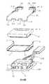
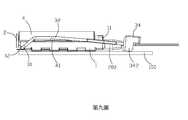
第一圖係本發明電連接器組合的立體圖;第二圖係第一圖所示電連接器組合另一角度的立體圖;第三圖係第一圖所示電連接器組合的立體分解圖;第四圖係第三圖所示電連接器組合另一角度的立體分解圖;第五圖係第一圖所示電連接器組合的部分分解圖;第六圖係本發明電連接器組合另一狀態的立體圖;第七圖係第六圖所示電連接器組合另一角度的立體圖;第八圖係第一圖所示電連接器組合的側視圖;及第九圖係第八圖所示電連接器組合另一狀態的側視圖。The first figure is a perspective view of the electrical connector assembly of the present invention; the second figure is a perspective view of the electrical connector assembly shown in the first figure from another angle; the third figure is a perspective exploded view of the electrical connector assembly shown in the first figure; Figure 4 is a perspective exploded view of the electrical connector assembly shown in Figure 3 from another angle; Figure 5 is a partial exploded view of the electrical connector assembly shown in Figure 1; Figure 6 is another electrical connector assembly of the present invention A perspective view of a state; Figure 7 is a perspective view of the electrical connector assembly shown in Figure 6 from another angle; Figure 8 is a side view of the electrical connector assembly shown in Figure 1; and Figure 9 is a perspective view of the electrical connector assembly shown in Figure 8. A side view showing another state of the electrical connector assembly.
以下,將結合第一圖至第九圖介紹本發明電連接器組合的實施方式。Hereinafter, the embodiments of the electrical connector assembly of the present invention will be described in conjunction with the first to the ninth figures.
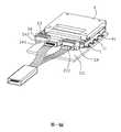
請參照第一圖至第五圖所示,本發明揭示了一種電連接器組合,用以電性連接光電收發模組(未圖示)與電路板100,其包括安裝於所述電路板100上的框體1、固定於所述框體1內的基座2、樞接於所述框體1的撥杆3以及組裝於所述基座2之上的光電模組4。所述撥杆3用於固定所述光電模組4,所述光電收發模組(未圖示)置於所述光電模組4內。所述基座2的前部組裝有用於傳輸光訊號的光纖模組200,所述光纖模組200與所述光電收發模組達成連接以實現光/電訊號的傳輸。所述撥杆3包括位於其後部且樞接於所述框體1上的樞接部31、將所述光電模組4抵接固定至所述基座2上的抵壓部32以及用於操作所述撥杆3且位於所述撥杆3前部的操作部33,所述撥杆3的操作部33包括包覆成型在所述撥杆3上的按壓塊34。Please refer to the first to fifth figures, the present invention discloses an electrical connector assembly for electrically connecting an optoelectronic transceiver module (not shown) and the
如第一圖至第四圖所示,所述按壓塊34設有沿水平方向延伸的按壓部341以及自所述按壓部341向所述電路板100凸伸的凸塊342,所述按壓部341為手指對所述按壓塊34的操作提供了較大的接觸面積。所述光纖模組200位於所述按壓部341與所述電路板100之間,重點參閱第八圖與第九圖,在上下方向上,所述凸塊342的高度大於所述光纖模組200的高度。如此可實現當過度向下按壓所述按壓塊34時所述凸塊342能夠與所述電路板100抵持並阻止所述按壓塊34繼續被向下按壓,從而能夠避免處於下方的光纖模組200由於被所述按壓塊34按壓而遭到損壞。在本實施例中,所述按壓塊34的上表面凸設有複數個沿前後方向延伸的肋條344。所述肋條344具有防滑功能,可方便手指對按壓塊34的穩定操作。As shown in the first to fourth figures, the
參閱第三圖至第四圖,所述抵壓部32成對設置並自所述樞接部31的兩端向前延伸。所述操作部33成對設置且分別自所述抵壓部32的前端相向延伸形成。如第一圖所示,所述操作部33位於所述基座2的前方。所述撥杆3對稱設置,所述兩操作部33彼此分離。Referring to the third to fourth figures, the
參閱第一圖和第二圖,所述凸塊342自所述按壓部341的下表面向下凸伸。在本實施例中,所述按壓塊34在所述按壓部341的下方形成位於所述凸塊342內側及前方的空腔343,所述光纖模組200部分容納於所述空腔343內。如此,在所述前後方向上,所述凸塊342的長度小於所述按壓部341的長度,從而為手指控制所述按壓塊34提供了足夠的操作空間,同時避免了由於所述按壓塊34或者手指在操作時碰到所述光纖模組200而對所述光纖模組200造成的損壞。Referring to the first and second figures, the
如第一圖至第七圖所示,所述撥杆3定義有閉合位置(如第一圖所示)與開啟位置(如第六圖所示),所述框體1的兩側設有向上延伸並彎折的鉤部11,所述光電模組4的兩側設有凸出的耳部41。當所述撥杆3位於所述閉合位置時,所述抵壓部32壓接於所述耳部41上方,所述鉤部11壓接於所述抵壓部32的上方以對所述撥杆3進行限位,從而使所述光電模組4固定於所述基座2之上。As shown in the first to seventh figures, the
請參第四圖和第五圖,所述樞接部31包括樞接於所述框體1的固定部311以及彎折設置的抵靠部312,所述框體1的後部包括用於樞接所述固定部311的限位部12,所述固定部311可在所述限位部12中旋轉從而使得所述撥杆3能夠以所述固定部311為中心旋轉。在本實施例中,所述撥杆3包括兩個所述固定部311且兩個所述固定部311在所述樞接部31上對稱設置。所述撥杆3包括兩個所述抵靠部312且兩個所述抵靠部312在所述樞接部31上對稱設置,同時,一對所述固定部311位於一對所述抵靠部312的外側。Please refer to the fourth and fifth figures, the
如第一圖、第六圖、第八圖和第九圖所示,當將所述撥杆3從所述閉合位置旋轉至所述開啟位置時,先向下按壓所述按壓部341,使所述按壓塊34帶動所述撥杆3向下發生彈性變形直到所述凸塊342接觸到所述電路板100而無法再下壓,再進一步向外撥動所述按壓部341以使所述撥杆3進一步脫離所述鉤部11,從而能夠順利轉動所述撥杆3至所述開啟位置同時使所述耳部41脫離所述抵壓部32的抵壓固定,進而可將所述光電模組4從所述基座1上拆除,該過程不會對位於所述空腔343中的光纖模組200造成損壞。As shown in the first, sixth, eighth and ninth figures, when the
重點參閱第六圖與第七圖,所述框體1的後部設有水平的延伸面13,在所述開啟位置時,所述抵靠部312抵靠於所述延伸面13,所述撥杆3的打開角度大於90度且所述抵壓部32呈略微向後傾斜的豎立狀態。所述抵壓部32的該略微向後傾斜的豎立狀態可以使所述凸塊342在所述上下方向上不與所述光電模組4重疊,以此避免所述凸塊342對所述光電模組4在安裝至所述基座2上的過程中產生干擾。Focusing on the sixth and seventh figures, the rear part of the
如第一圖至第五圖所示,所述基座2的後部凸設有豎直的抵擋面21(標號見第四圖),當所述撥杆3旋轉至所述閉合位置時,所述抵靠部312抵靠於所述抵擋面21以增加所述撥杆3對所述光電模組4固定的穩固性。As shown in the first to fifth figures, the rear of the
綜上所述,本發明確已符合發明專利之要件,爰依法提出專利申請。惟,以上所述僅為本發明之較佳實施方式,自不能以此限定本發明之權利範圍。舉凡所屬技術領域中具有通常知識者爰依本發明之精神所作之等效修飾或變化,皆仍涵蓋於後附之申請專利範圍內。In summary, this publication clearly meets the requirements of an invention patent, and Yan filed a patent application in accordance with the law. However, the above descriptions are only the preferred embodiments of the present invention, and the scope of rights of the present invention cannot be limited by this. All equivalent modifications or changes made by those with ordinary knowledge in the technical field based on the spirit of the present invention are still covered in the scope of the appended patent application.
1:框體1: frame
100:電路板100: circuit board
11:鉤部11: hook
12:限位部12: Limiting part
2:基座2: pedestal
200:光纖模組200: Optical fiber module
31:樞接部31: Pivot
32:抵壓部32: Pressure part
34:按壓塊34: Press block
342:凸塊342: Bump
4:光電模組4: Optoelectronic module
41:耳部41: Ear
Claims (9)
Translated fromChineseApplications Claiming Priority (3)
| Application Number | Priority Date | Filing Date | Title |
|---|---|---|---|
| CN201610675084.8 | 2016-08-17 | ||
| ??201610675084.8 | 2016-08-17 | ||
| CN201610675084.8ACN107768910B (en) | 2016-08-17 | 2016-08-17 | Electric connector combination |
Publications (2)
| Publication Number | Publication Date |
|---|---|
| TW201810827A TW201810827A (en) | 2018-03-16 |
| TWI742136Btrue TWI742136B (en) | 2021-10-11 |
Family
ID=61191470
Family Applications (1)
| Application Number | Title | Priority Date | Filing Date |
|---|---|---|---|
| TW106127705ATWI742136B (en) | 2016-08-17 | 2017-08-16 | Electrical connector assembly |
Country Status (3)
| Country | Link |
|---|---|
| US (1) | US10386591B2 (en) |
| CN (1) | CN107768910B (en) |
| TW (1) | TWI742136B (en) |
Families Citing this family (1)
| Publication number | Priority date | Publication date | Assignee | Title |
|---|---|---|---|---|
| TWI874083B (en)* | 2023-12-29 | 2025-02-21 | 利鴻科技股份有限公司 | Electrical connector structure |
Citations (4)
| Publication number | Priority date | Publication date | Assignee | Title |
|---|---|---|---|---|
| US20060029336A1 (en)* | 2004-08-06 | 2006-02-09 | Gunther Peter U | Opto-electrical module for optical signals from at least two optical data channels for arranging on a main circuit board of a component assembly and opto-electrical component assembly |
| US20130294732A1 (en)* | 2012-03-05 | 2013-11-07 | Nanoprecision Products, Inc. | Hermetic optical fiber alignment assembly having integrated optical element |
| TW201445207A (en)* | 2013-05-30 | 2014-12-01 | Hon Hai Prec Ind Co Ltd | Retention module |
| US20160006170A1 (en)* | 2014-07-01 | 2016-01-07 | Hon Hai Precision Industry Co., Ltd. | Electrical connector assembly with jumper element assembled thereon |
Family Cites Families (8)
| Publication number | Priority date | Publication date | Assignee | Title |
|---|---|---|---|---|
| US5011426A (en)* | 1990-02-02 | 1991-04-30 | Molex Incorporated | Electrical connector assembly for vehicular suspension system component |
| DE50210456D1 (en)* | 2001-03-01 | 2007-08-23 | Huber+Suhner Ag | FIBER OPTIC CONNECTOR SYSTEM |
| US20080160814A1 (en)* | 2006-12-28 | 2008-07-03 | Hon Hai Precision Ind. Co., Ltd. | Land grid array connector assembly with pick up cap |
| TWM331235U (en) | 2007-08-24 | 2008-04-21 | Hon Hai Prec Ind Co Ltd | Electrical connector |
| TWM375313U (en) | 2009-08-04 | 2010-03-01 | Hon Hai Prec Ind Co Ltd | Electrical connector |
| TWM491975U (en)* | 2014-05-28 | 2014-12-11 | Hon Hai Prec Ind Co Ltd | Electrical connector assembly |
| CN203983618U (en)* | 2014-05-29 | 2014-12-03 | 富士康(昆山)电脑接插件有限公司 | Electric coupler component |
| US9730351B2 (en) | 2014-07-01 | 2017-08-08 | Foxconn Interconnect Technology Limited | Electrical connector assembly with holding member |
- 2016
- 2016-08-17CNCN201610675084.8Apatent/CN107768910B/enactiveActive
- 2017
- 2017-08-16TWTW106127705Apatent/TWI742136B/ennot_activeIP Right Cessation
- 2017-08-17USUS15/680,165patent/US10386591B2/ennot_activeExpired - Fee Related
Patent Citations (4)
| Publication number | Priority date | Publication date | Assignee | Title |
|---|---|---|---|---|
| US20060029336A1 (en)* | 2004-08-06 | 2006-02-09 | Gunther Peter U | Opto-electrical module for optical signals from at least two optical data channels for arranging on a main circuit board of a component assembly and opto-electrical component assembly |
| US20130294732A1 (en)* | 2012-03-05 | 2013-11-07 | Nanoprecision Products, Inc. | Hermetic optical fiber alignment assembly having integrated optical element |
| TW201445207A (en)* | 2013-05-30 | 2014-12-01 | Hon Hai Prec Ind Co Ltd | Retention module |
| US20160006170A1 (en)* | 2014-07-01 | 2016-01-07 | Hon Hai Precision Industry Co., Ltd. | Electrical connector assembly with jumper element assembled thereon |
Also Published As
| Publication number | Publication date |
|---|---|
| US10386591B2 (en) | 2019-08-20 |
| CN107768910A (en) | 2018-03-06 |
| TW201810827A (en) | 2018-03-16 |
| CN107768910B (en) | 2020-09-25 |
| US20180052292A1 (en) | 2018-02-22 |
Similar Documents
| Publication | Publication Date | Title |
|---|---|---|
| JP3177657U (en) | Electrical connector | |
| JP5905922B2 (en) | Optical module connector system and method | |
| US20090274468A1 (en) | Transceiver module with releasing mechanism | |
| JP2010245040A (en) | Electrical connector | |
| TWI742136B (en) | Electrical connector assembly | |
| JP5920504B1 (en) | Electrical connector | |
| CN103260369A (en) | Cover plate mechanism and related electronic device | |
| JP6354601B2 (en) | Communication module | |
| CN102222839B (en) | Crystal head | |
| TWM552196U (en) | Miniature electrical plug connector | |
| TWM593675U (en) | Modular connector | |
| CN115668053A (en) | Camera unit | |
| KR100608830B1 (en) | Mobile communication terminal with ground spring finger | |
| JP2002184517A (en) | Connection structure between electrical equipment and connection cord | |
| CN110768727A (en) | Optical transceiver | |
| KR101002563B1 (en) | Connector for F.C. film | |
| CN112783340B (en) | Mouse device | |
| CN104362457B (en) | Electrical connector | |
| CN109599703B (en) | Flexible circuit board golden finger connector and using method thereof | |
| TWI642985B (en) | Transceiver module | |
| JP2004138708A (en) | Optical connector | |
| KR200476958Y1 (en) | Holder of tablet smart device | |
| TWI578054B (en) | Sfp transceiver | |
| TWI871041B (en) | Glasses type display device | |
| CN221125004U (en) | AR glasses |
Legal Events
| Date | Code | Title | Description |
|---|---|---|---|
| MM4A | Annulment or lapse of patent due to non-payment of fees |