TWI741743B - Backplane connector - Google Patents
Backplane connectorDownload PDFInfo
- Publication number
- TWI741743B TWI741743BTW109128294ATW109128294ATWI741743BTW I741743 BTWI741743 BTW I741743BTW 109128294 ATW109128294 ATW 109128294ATW 109128294 ATW109128294 ATW 109128294ATW I741743 BTWI741743 BTW I741743B
- Authority
- TW
- Taiwan
- Prior art keywords
- protrusion
- ground terminal
- aforementioned
- terminal
- extension
- Prior art date
Links
Images


Classifications
- H—ELECTRICITY
- H01—ELECTRIC ELEMENTS
- H01R—ELECTRICALLY-CONDUCTIVE CONNECTIONS; STRUCTURAL ASSOCIATIONS OF A PLURALITY OF MUTUALLY-INSULATED ELECTRICAL CONNECTING ELEMENTS; COUPLING DEVICES; CURRENT COLLECTORS
- H01R13/00—Details of coupling devices of the kinds covered by groups H01R12/70 or H01R24/00 - H01R33/00
- H01R13/646—Details of coupling devices of the kinds covered by groups H01R12/70 or H01R24/00 - H01R33/00 specially adapted for high-frequency, e.g. structures providing an impedance match or phase match
- H01R13/6461—Means for preventing cross-talk
- H01R13/6471—Means for preventing cross-talk by special arrangement of ground and signal conductors, e.g. GSGS [Ground-Signal-Ground-Signal]
- H—ELECTRICITY
- H01—ELECTRIC ELEMENTS
- H01R—ELECTRICALLY-CONDUCTIVE CONNECTIONS; STRUCTURAL ASSOCIATIONS OF A PLURALITY OF MUTUALLY-INSULATED ELECTRICAL CONNECTING ELEMENTS; COUPLING DEVICES; CURRENT COLLECTORS
- H01R13/00—Details of coupling devices of the kinds covered by groups H01R12/70 or H01R24/00 - H01R33/00
- H01R13/646—Details of coupling devices of the kinds covered by groups H01R12/70 or H01R24/00 - H01R33/00 specially adapted for high-frequency, e.g. structures providing an impedance match or phase match
- H01R13/6461—Means for preventing cross-talk
- H—ELECTRICITY
- H01—ELECTRIC ELEMENTS
- H01R—ELECTRICALLY-CONDUCTIVE CONNECTIONS; STRUCTURAL ASSOCIATIONS OF A PLURALITY OF MUTUALLY-INSULATED ELECTRICAL CONNECTING ELEMENTS; COUPLING DEVICES; CURRENT COLLECTORS
- H01R13/00—Details of coupling devices of the kinds covered by groups H01R12/70 or H01R24/00 - H01R33/00
- H01R13/646—Details of coupling devices of the kinds covered by groups H01R12/70 or H01R24/00 - H01R33/00 specially adapted for high-frequency, e.g. structures providing an impedance match or phase match
- H—ELECTRICITY
- H01—ELECTRIC ELEMENTS
- H01R—ELECTRICALLY-CONDUCTIVE CONNECTIONS; STRUCTURAL ASSOCIATIONS OF A PLURALITY OF MUTUALLY-INSULATED ELECTRICAL CONNECTING ELEMENTS; COUPLING DEVICES; CURRENT COLLECTORS
- H01R12/00—Structural associations of a plurality of mutually-insulated electrical connecting elements, specially adapted for printed circuits, e.g. printed circuit boards [PCB], flat or ribbon cables, or like generally planar structures, e.g. terminal strips, terminal blocks; Coupling devices specially adapted for printed circuits, flat or ribbon cables, or like generally planar structures; Terminals specially adapted for contact with, or insertion into, printed circuits, flat or ribbon cables, or like generally planar structures
- H01R12/50—Fixed connections
- H01R12/51—Fixed connections for rigid printed circuits or like structures
- H01R12/55—Fixed connections for rigid printed circuits or like structures characterised by the terminals
- H01R12/58—Fixed connections for rigid printed circuits or like structures characterised by the terminals terminals for insertion into holes
- H01R12/585—Terminals having a press fit or a compliant portion and a shank passing through a hole in the printed circuit board
- H—ELECTRICITY
- H01—ELECTRIC ELEMENTS
- H01R—ELECTRICALLY-CONDUCTIVE CONNECTIONS; STRUCTURAL ASSOCIATIONS OF A PLURALITY OF MUTUALLY-INSULATED ELECTRICAL CONNECTING ELEMENTS; COUPLING DEVICES; CURRENT COLLECTORS
- H01R12/00—Structural associations of a plurality of mutually-insulated electrical connecting elements, specially adapted for printed circuits, e.g. printed circuit boards [PCB], flat or ribbon cables, or like generally planar structures, e.g. terminal strips, terminal blocks; Coupling devices specially adapted for printed circuits, flat or ribbon cables, or like generally planar structures; Terminals specially adapted for contact with, or insertion into, printed circuits, flat or ribbon cables, or like generally planar structures
- H01R12/70—Coupling devices
- H01R12/71—Coupling devices for rigid printing circuits or like structures
- H01R12/712—Coupling devices for rigid printing circuits or like structures co-operating with the surface of the printed circuit or with a coupling device exclusively provided on the surface of the printed circuit
- H01R12/716—Coupling device provided on the PCB
- H—ELECTRICITY
- H01—ELECTRIC ELEMENTS
- H01R—ELECTRICALLY-CONDUCTIVE CONNECTIONS; STRUCTURAL ASSOCIATIONS OF A PLURALITY OF MUTUALLY-INSULATED ELECTRICAL CONNECTING ELEMENTS; COUPLING DEVICES; CURRENT COLLECTORS
- H01R12/00—Structural associations of a plurality of mutually-insulated electrical connecting elements, specially adapted for printed circuits, e.g. printed circuit boards [PCB], flat or ribbon cables, or like generally planar structures, e.g. terminal strips, terminal blocks; Coupling devices specially adapted for printed circuits, flat or ribbon cables, or like generally planar structures; Terminals specially adapted for contact with, or insertion into, printed circuits, flat or ribbon cables, or like generally planar structures
- H01R12/70—Coupling devices
- H01R12/71—Coupling devices for rigid printing circuits or like structures
- H01R12/72—Coupling devices for rigid printing circuits or like structures coupling with the edge of the rigid printed circuits or like structures
- H01R12/722—Coupling devices for rigid printing circuits or like structures coupling with the edge of the rigid printed circuits or like structures coupling devices mounted on the edge of the printed circuits
- H01R12/724—Coupling devices for rigid printing circuits or like structures coupling with the edge of the rigid printed circuits or like structures coupling devices mounted on the edge of the printed circuits containing contact members forming a right angle
- H—ELECTRICITY
- H01—ELECTRIC ELEMENTS
- H01R—ELECTRICALLY-CONDUCTIVE CONNECTIONS; STRUCTURAL ASSOCIATIONS OF A PLURALITY OF MUTUALLY-INSULATED ELECTRICAL CONNECTING ELEMENTS; COUPLING DEVICES; CURRENT COLLECTORS
- H01R13/00—Details of coupling devices of the kinds covered by groups H01R12/70 or H01R24/00 - H01R33/00
- H01R13/02—Contact members
- H01R13/20—Pins, blades, or sockets shaped, or provided with separate member, to retain co-operating parts together
- H—ELECTRICITY
- H01—ELECTRIC ELEMENTS
- H01R—ELECTRICALLY-CONDUCTIVE CONNECTIONS; STRUCTURAL ASSOCIATIONS OF A PLURALITY OF MUTUALLY-INSULATED ELECTRICAL CONNECTING ELEMENTS; COUPLING DEVICES; CURRENT COLLECTORS
- H01R13/00—Details of coupling devices of the kinds covered by groups H01R12/70 or H01R24/00 - H01R33/00
- H01R13/40—Securing contact members in or to a base or case; Insulating of contact members
- H—ELECTRICITY
- H01—ELECTRIC ELEMENTS
- H01R—ELECTRICALLY-CONDUCTIVE CONNECTIONS; STRUCTURAL ASSOCIATIONS OF A PLURALITY OF MUTUALLY-INSULATED ELECTRICAL CONNECTING ELEMENTS; COUPLING DEVICES; CURRENT COLLECTORS
- H01R13/00—Details of coupling devices of the kinds covered by groups H01R12/70 or H01R24/00 - H01R33/00
- H01R13/46—Bases; Cases
- H01R13/502—Bases; Cases composed of different pieces
- H01R13/504—Bases; Cases composed of different pieces different pieces being moulded, cemented, welded, e.g. ultrasonic, or swaged together
- H—ELECTRICITY
- H01—ELECTRIC ELEMENTS
- H01R—ELECTRICALLY-CONDUCTIVE CONNECTIONS; STRUCTURAL ASSOCIATIONS OF A PLURALITY OF MUTUALLY-INSULATED ELECTRICAL CONNECTING ELEMENTS; COUPLING DEVICES; CURRENT COLLECTORS
- H01R13/00—Details of coupling devices of the kinds covered by groups H01R12/70 or H01R24/00 - H01R33/00
- H01R13/46—Bases; Cases
- H01R13/514—Bases; Cases composed as a modular blocks or assembly, i.e. composed of co-operating parts provided with contact members or holding contact members between them
- H—ELECTRICITY
- H01—ELECTRIC ELEMENTS
- H01R—ELECTRICALLY-CONDUCTIVE CONNECTIONS; STRUCTURAL ASSOCIATIONS OF A PLURALITY OF MUTUALLY-INSULATED ELECTRICAL CONNECTING ELEMENTS; COUPLING DEVICES; CURRENT COLLECTORS
- H01R13/00—Details of coupling devices of the kinds covered by groups H01R12/70 or H01R24/00 - H01R33/00
- H01R13/46—Bases; Cases
- H01R13/516—Means for holding or embracing insulating body, e.g. casing, hoods
- H01R13/518—Means for holding or embracing insulating body, e.g. casing, hoods for holding or embracing several coupling parts, e.g. frames
- H—ELECTRICITY
- H01—ELECTRIC ELEMENTS
- H01R—ELECTRICALLY-CONDUCTIVE CONNECTIONS; STRUCTURAL ASSOCIATIONS OF A PLURALITY OF MUTUALLY-INSULATED ELECTRICAL CONNECTING ELEMENTS; COUPLING DEVICES; CURRENT COLLECTORS
- H01R13/00—Details of coupling devices of the kinds covered by groups H01R12/70 or H01R24/00 - H01R33/00
- H01R13/646—Details of coupling devices of the kinds covered by groups H01R12/70 or H01R24/00 - H01R33/00 specially adapted for high-frequency, e.g. structures providing an impedance match or phase match
- H01R13/6473—Impedance matching
- H—ELECTRICITY
- H01—ELECTRIC ELEMENTS
- H01R—ELECTRICALLY-CONDUCTIVE CONNECTIONS; STRUCTURAL ASSOCIATIONS OF A PLURALITY OF MUTUALLY-INSULATED ELECTRICAL CONNECTING ELEMENTS; COUPLING DEVICES; CURRENT COLLECTORS
- H01R13/00—Details of coupling devices of the kinds covered by groups H01R12/70 or H01R24/00 - H01R33/00
- H01R13/648—Protective earth or shield arrangements on coupling devices, e.g. anti-static shielding
- H01R13/652—Protective earth or shield arrangements on coupling devices, e.g. anti-static shielding with earth pin, blade or socket
- H—ELECTRICITY
- H01—ELECTRIC ELEMENTS
- H01R—ELECTRICALLY-CONDUCTIVE CONNECTIONS; STRUCTURAL ASSOCIATIONS OF A PLURALITY OF MUTUALLY-INSULATED ELECTRICAL CONNECTING ELEMENTS; COUPLING DEVICES; CURRENT COLLECTORS
- H01R13/00—Details of coupling devices of the kinds covered by groups H01R12/70 or H01R24/00 - H01R33/00
- H01R13/648—Protective earth or shield arrangements on coupling devices, e.g. anti-static shielding
- H01R13/658—High frequency shielding arrangements, e.g. against EMI [Electro-Magnetic Interference] or EMP [Electro-Magnetic Pulse]
- H01R13/6581—Shield structure
- H01R13/6582—Shield structure with resilient means for engaging mating connector
- H01R13/6583—Shield structure with resilient means for engaging mating connector with separate conductive resilient members between mating shield members
- H01R13/6584—Shield structure with resilient means for engaging mating connector with separate conductive resilient members between mating shield members formed by conductive elastomeric members, e.g. flat gaskets or O-rings
- H—ELECTRICITY
- H01—ELECTRIC ELEMENTS
- H01R—ELECTRICALLY-CONDUCTIVE CONNECTIONS; STRUCTURAL ASSOCIATIONS OF A PLURALITY OF MUTUALLY-INSULATED ELECTRICAL CONNECTING ELEMENTS; COUPLING DEVICES; CURRENT COLLECTORS
- H01R13/00—Details of coupling devices of the kinds covered by groups H01R12/70 or H01R24/00 - H01R33/00
- H01R13/648—Protective earth or shield arrangements on coupling devices, e.g. anti-static shielding
- H01R13/658—High frequency shielding arrangements, e.g. against EMI [Electro-Magnetic Interference] or EMP [Electro-Magnetic Pulse]
- H01R13/6581—Shield structure
- H01R13/6585—Shielding material individually surrounding or interposed between mutually spaced contacts
- H01R13/6586—Shielding material individually surrounding or interposed between mutually spaced contacts for separating multiple connector modules
- H01R13/6587—Shielding material individually surrounding or interposed between mutually spaced contacts for separating multiple connector modules for mounting on PCBs
- H—ELECTRICITY
- H01—ELECTRIC ELEMENTS
- H01R—ELECTRICALLY-CONDUCTIVE CONNECTIONS; STRUCTURAL ASSOCIATIONS OF A PLURALITY OF MUTUALLY-INSULATED ELECTRICAL CONNECTING ELEMENTS; COUPLING DEVICES; CURRENT COLLECTORS
- H01R13/00—Details of coupling devices of the kinds covered by groups H01R12/70 or H01R24/00 - H01R33/00
- H01R13/648—Protective earth or shield arrangements on coupling devices, e.g. anti-static shielding
- H01R13/658—High frequency shielding arrangements, e.g. against EMI [Electro-Magnetic Interference] or EMP [Electro-Magnetic Pulse]
- H01R13/6581—Shield structure
- H01R13/6585—Shielding material individually surrounding or interposed between mutually spaced contacts
- H01R13/6588—Shielding material individually surrounding or interposed between mutually spaced contacts with through openings for individual contacts
- H—ELECTRICITY
- H01—ELECTRIC ELEMENTS
- H01R—ELECTRICALLY-CONDUCTIVE CONNECTIONS; STRUCTURAL ASSOCIATIONS OF A PLURALITY OF MUTUALLY-INSULATED ELECTRICAL CONNECTING ELEMENTS; COUPLING DEVICES; CURRENT COLLECTORS
- H01R13/00—Details of coupling devices of the kinds covered by groups H01R12/70 or H01R24/00 - H01R33/00
- H01R13/648—Protective earth or shield arrangements on coupling devices, e.g. anti-static shielding
- H01R13/658—High frequency shielding arrangements, e.g. against EMI [Electro-Magnetic Interference] or EMP [Electro-Magnetic Pulse]
- H01R13/6591—Specific features or arrangements of connection of shield to conductive members
- H—ELECTRICITY
- H01—ELECTRIC ELEMENTS
- H01R—ELECTRICALLY-CONDUCTIVE CONNECTIONS; STRUCTURAL ASSOCIATIONS OF A PLURALITY OF MUTUALLY-INSULATED ELECTRICAL CONNECTING ELEMENTS; COUPLING DEVICES; CURRENT COLLECTORS
- H01R43/00—Apparatus or processes specially adapted for manufacturing, assembling, maintaining, or repairing of line connectors or current collectors or for joining electric conductors
- H01R43/20—Apparatus or processes specially adapted for manufacturing, assembling, maintaining, or repairing of line connectors or current collectors or for joining electric conductors for assembling or disassembling contact members with insulating base, case or sleeve
- H01R43/24—Assembling by moulding on contact members
- H—ELECTRICITY
- H05—ELECTRIC TECHNIQUES NOT OTHERWISE PROVIDED FOR
- H05K—PRINTED CIRCUITS; CASINGS OR CONSTRUCTIONAL DETAILS OF ELECTRIC APPARATUS; MANUFACTURE OF ASSEMBLAGES OF ELECTRICAL COMPONENTS
- H05K1/00—Printed circuits
- H05K1/02—Details
- H05K1/11—Printed elements for providing electric connections to or between printed circuits
- H05K1/115—Via connections; Lands around holes or via connections
- H—ELECTRICITY
- H05—ELECTRIC TECHNIQUES NOT OTHERWISE PROVIDED FOR
- H05K—PRINTED CIRCUITS; CASINGS OR CONSTRUCTIONAL DETAILS OF ELECTRIC APPARATUS; MANUFACTURE OF ASSEMBLAGES OF ELECTRICAL COMPONENTS
- H05K3/00—Apparatus or processes for manufacturing printed circuits
- H05K3/30—Assembling printed circuits with electric components, e.g. with resistor
- H05K3/306—Lead-in-hole components, e.g. affixing or retention before soldering, spacing means
- H—ELECTRICITY
- H05—ELECTRIC TECHNIQUES NOT OTHERWISE PROVIDED FOR
- H05K—PRINTED CIRCUITS; CASINGS OR CONSTRUCTIONAL DETAILS OF ELECTRIC APPARATUS; MANUFACTURE OF ASSEMBLAGES OF ELECTRICAL COMPONENTS
- H05K3/00—Apparatus or processes for manufacturing printed circuits
- H05K3/30—Assembling printed circuits with electric components, e.g. with resistor
- H05K3/32—Assembling printed circuits with electric components, e.g. with resistor electrically connecting electric components or wires to printed circuits
- H05K3/34—Assembling printed circuits with electric components, e.g. with resistor electrically connecting electric components or wires to printed circuits by soldering
- H05K3/3447—Lead-in-hole components
- H—ELECTRICITY
- H01—ELECTRIC ELEMENTS
- H01R—ELECTRICALLY-CONDUCTIVE CONNECTIONS; STRUCTURAL ASSOCIATIONS OF A PLURALITY OF MUTUALLY-INSULATED ELECTRICAL CONNECTING ELEMENTS; COUPLING DEVICES; CURRENT COLLECTORS
- H01R12/00—Structural associations of a plurality of mutually-insulated electrical connecting elements, specially adapted for printed circuits, e.g. printed circuit boards [PCB], flat or ribbon cables, or like generally planar structures, e.g. terminal strips, terminal blocks; Coupling devices specially adapted for printed circuits, flat or ribbon cables, or like generally planar structures; Terminals specially adapted for contact with, or insertion into, printed circuits, flat or ribbon cables, or like generally planar structures
- H01R12/70—Coupling devices
- H01R12/71—Coupling devices for rigid printing circuits or like structures
- H01R12/712—Coupling devices for rigid printing circuits or like structures co-operating with the surface of the printed circuit or with a coupling device exclusively provided on the surface of the printed circuit
- H—ELECTRICITY
- H01—ELECTRIC ELEMENTS
- H01R—ELECTRICALLY-CONDUCTIVE CONNECTIONS; STRUCTURAL ASSOCIATIONS OF A PLURALITY OF MUTUALLY-INSULATED ELECTRICAL CONNECTING ELEMENTS; COUPLING DEVICES; CURRENT COLLECTORS
- H01R12/00—Structural associations of a plurality of mutually-insulated electrical connecting elements, specially adapted for printed circuits, e.g. printed circuit boards [PCB], flat or ribbon cables, or like generally planar structures, e.g. terminal strips, terminal blocks; Coupling devices specially adapted for printed circuits, flat or ribbon cables, or like generally planar structures; Terminals specially adapted for contact with, or insertion into, printed circuits, flat or ribbon cables, or like generally planar structures
- H01R12/70—Coupling devices
- H01R12/71—Coupling devices for rigid printing circuits or like structures
- H01R12/72—Coupling devices for rigid printing circuits or like structures coupling with the edge of the rigid printed circuits or like structures
- H01R12/722—Coupling devices for rigid printing circuits or like structures coupling with the edge of the rigid printed circuits or like structures coupling devices mounted on the edge of the printed circuits
- H—ELECTRICITY
- H01—ELECTRIC ELEMENTS
- H01R—ELECTRICALLY-CONDUCTIVE CONNECTIONS; STRUCTURAL ASSOCIATIONS OF A PLURALITY OF MUTUALLY-INSULATED ELECTRICAL CONNECTING ELEMENTS; COUPLING DEVICES; CURRENT COLLECTORS
- H01R13/00—Details of coupling devices of the kinds covered by groups H01R12/70 or H01R24/00 - H01R33/00
- H01R13/46—Bases; Cases
- H01R13/502—Bases; Cases composed of different pieces
- H—ELECTRICITY
- H01—ELECTRIC ELEMENTS
- H01R—ELECTRICALLY-CONDUCTIVE CONNECTIONS; STRUCTURAL ASSOCIATIONS OF A PLURALITY OF MUTUALLY-INSULATED ELECTRICAL CONNECTING ELEMENTS; COUPLING DEVICES; CURRENT COLLECTORS
- H01R13/00—Details of coupling devices of the kinds covered by groups H01R12/70 or H01R24/00 - H01R33/00
- H01R13/646—Details of coupling devices of the kinds covered by groups H01R12/70 or H01R24/00 - H01R33/00 specially adapted for high-frequency, e.g. structures providing an impedance match or phase match
- H01R13/6473—Impedance matching
- H01R13/6474—Impedance matching by variation of conductive properties, e.g. by dimension variations
- H—ELECTRICITY
- H05—ELECTRIC TECHNIQUES NOT OTHERWISE PROVIDED FOR
- H05K—PRINTED CIRCUITS; CASINGS OR CONSTRUCTIONAL DETAILS OF ELECTRIC APPARATUS; MANUFACTURE OF ASSEMBLAGES OF ELECTRICAL COMPONENTS
- H05K2201/00—Indexing scheme relating to printed circuits covered by H05K1/00
- H05K2201/09—Shape and layout
- H05K2201/09209—Shape and layout details of conductors
- H05K2201/09218—Conductive traces
- H05K2201/09236—Parallel layout
- H—ELECTRICITY
- H05—ELECTRIC TECHNIQUES NOT OTHERWISE PROVIDED FOR
- H05K—PRINTED CIRCUITS; CASINGS OR CONSTRUCTIONAL DETAILS OF ELECTRIC APPARATUS; MANUFACTURE OF ASSEMBLAGES OF ELECTRICAL COMPONENTS
- H05K2201/00—Indexing scheme relating to printed circuits covered by H05K1/00
- H05K2201/10—Details of components or other objects attached to or integrated in a printed circuit board
- H05K2201/10007—Types of components
- H05K2201/10189—Non-printed connector
- H—ELECTRICITY
- H05—ELECTRIC TECHNIQUES NOT OTHERWISE PROVIDED FOR
- H05K—PRINTED CIRCUITS; CASINGS OR CONSTRUCTIONAL DETAILS OF ELECTRIC APPARATUS; MANUFACTURE OF ASSEMBLAGES OF ELECTRICAL COMPONENTS
- H05K2201/00—Indexing scheme relating to printed circuits covered by H05K1/00
- H05K2201/10—Details of components or other objects attached to or integrated in a printed circuit board
- H05K2201/10227—Other objects, e.g. metallic pieces
- H05K2201/10371—Shields or metal cases
- H—ELECTRICITY
- H05—ELECTRIC TECHNIQUES NOT OTHERWISE PROVIDED FOR
- H05K—PRINTED CIRCUITS; CASINGS OR CONSTRUCTIONAL DETAILS OF ELECTRIC APPARATUS; MANUFACTURE OF ASSEMBLAGES OF ELECTRICAL COMPONENTS
- H05K2201/00—Indexing scheme relating to printed circuits covered by H05K1/00
- H05K2201/10—Details of components or other objects attached to or integrated in a printed circuit board
- H05K2201/10613—Details of electrical connections of non-printed components, e.g. special leads
- H05K2201/10742—Details of leads
- H05K2201/1075—Shape details
- H05K2201/1078—Leads having locally deformed portion, e.g. for retention
- H—ELECTRICITY
- H05—ELECTRIC TECHNIQUES NOT OTHERWISE PROVIDED FOR
- H05K—PRINTED CIRCUITS; CASINGS OR CONSTRUCTIONAL DETAILS OF ELECTRIC APPARATUS; MANUFACTURE OF ASSEMBLAGES OF ELECTRICAL COMPONENTS
- H05K2201/00—Indexing scheme relating to printed circuits covered by H05K1/00
- H05K2201/10—Details of components or other objects attached to or integrated in a printed circuit board
- H05K2201/10613—Details of electrical connections of non-printed components, e.g. special leads
- H05K2201/10742—Details of leads
- H05K2201/1075—Shape details
- H05K2201/10871—Leads having an integral insert stop
- Y—GENERAL TAGGING OF NEW TECHNOLOGICAL DEVELOPMENTS; GENERAL TAGGING OF CROSS-SECTIONAL TECHNOLOGIES SPANNING OVER SEVERAL SECTIONS OF THE IPC; TECHNICAL SUBJECTS COVERED BY FORMER USPC CROSS-REFERENCE ART COLLECTIONS [XRACs] AND DIGESTS
- Y02—TECHNOLOGIES OR APPLICATIONS FOR MITIGATION OR ADAPTATION AGAINST CLIMATE CHANGE
- Y02E—REDUCTION OF GREENHOUSE GAS [GHG] EMISSIONS, RELATED TO ENERGY GENERATION, TRANSMISSION OR DISTRIBUTION
- Y02E10/00—Energy generation through renewable energy sources
- Y02E10/50—Photovoltaic [PV] energy
Landscapes
- Engineering & Computer Science (AREA)
- Manufacturing & Machinery (AREA)
- Microelectronics & Electronic Packaging (AREA)
- Details Of Connecting Devices For Male And Female Coupling (AREA)
- Mechanical Coupling Of Light Guides (AREA)
- Magnetic Heads (AREA)
Abstract
Description
Translated fromChinese本發明涉及一種背板連接器,屬於連接器技術領域。The invention relates to a backplane connector, which belongs to the technical field of connectors.
本發明要求了申請日為2020年06月19日,申請號為202010567796.4,發明創造名稱為“背板連接器組件”的中國專利申請的優先權,其全部內容藉由引用結合於本發明中。The present invention claims the priority of a Chinese patent application whose application date is June 19, 2020, the application number is 202010567796.4, and the invention-creation name is "backplane connector assembly", the entire content of which is incorporated into the present invention by reference.
習知的背板連接器通常包括絕緣殼體以及安裝於絕緣殼體的複數端子模組,其中每一端子模組包括絕緣框架、嵌入成型於絕緣框架中的複數導電端子以及安裝於絕緣框架至少一側的金屬屏蔽片。複數導電端子通常包括複數對差分訊號端子、位於每一對差分訊號端子的一側的第一接地端子以及位於每一對差分訊號端子的另一相對側的第二接地端子。第一接地端子、第二接地端子以及金屬屏蔽片給差分訊號端子提供屏蔽,俾降低訊號串擾,提高訊號傳輸的品質。The conventional backplane connector usually includes an insulating housing and a plurality of terminal modules mounted on the insulating housing. Each terminal module includes an insulating frame, a plurality of conductive terminals embedded in the insulating frame, and at least Metal shield on one side. The plurality of conductive terminals usually include a plurality of pairs of differential signal terminals, a first ground terminal located on one side of each pair of differential signal terminals, and a second ground terminal located on the opposite side of each pair of differential signal terminals. The first grounding terminal, the second grounding terminal and the metal shielding sheet provide shielding for the differential signal terminals to reduce signal crosstalk and improve the quality of signal transmission.
然,習知技術中對差分訊號端子的屏蔽仍有改進空間。However, there is still room for improvement in the shielding of the differential signal terminals in the prior art.
本發明的目的在於提供一種屏蔽效果較好的背板連接器。The purpose of the present invention is to provide a backplane connector with better shielding effect.
為實現前述目的,本發明採用如下技術方案:一種背板連接器,其包括端子模組,前述端子模組包括:To achieve the foregoing objective, the present invention adopts the following technical solutions: a backplane connector including a terminal module, and the foregoing terminal module includes:
複數導電端子,前述導電端子包括連接部以及接觸部;A plurality of conductive terminals, the aforementioned conductive terminal includes a connecting portion and a contact portion;
絕緣支架,前述絕緣支架固定於前述連接部上;An insulating support, the aforementioned insulating support is fixed on the aforementioned connecting portion;
第一金屬屏蔽片,前述第一金屬屏蔽片設有位於前述導電端子的接觸部的一側的第一延伸部;以及A first metal shielding sheet, the first metal shielding sheet is provided with a first extension located on one side of the contact portion of the conductive terminal; and
第二金屬屏蔽片,前述第二金屬屏蔽片設有位於前述導電端子的接觸部的另一相對側的第二延伸部;A second metal shielding sheet, wherein the second metal shielding sheet is provided with a second extension portion located on the other opposite side of the contact portion of the conductive terminal;
前述導電端子包括差分訊號端子、第一接地端子以及第二接地端子,其中前述差分訊號端子位於前述第一接地端子與前述第二接地端子之間;The aforementioned conductive terminal includes a differential signal terminal, a first ground terminal, and a second ground terminal, wherein the differential signal terminal is located between the first ground terminal and the second ground terminal;
前述第一延伸部設有向前述第一接地端子凸出的第一凸起以及向前述第二接地端子凸出的第二凸起;The first extension portion is provided with a first protrusion protruding toward the first ground terminal and a second protrusion protruding toward the second ground terminal;
前述第二延伸部設有向前述第一接地端子凸出的第三凸起以及向前述第二接地端子凸出的第四凸起;The second extension portion is provided with a third protrusion protruding toward the first ground terminal and a fourth protrusion protruding toward the second ground terminal;
前述第一凸起及前述第三凸起分別與前述第一接地端子的接觸部的兩相對側面相接觸,前述第二凸起及前述第四凸起分別與前述第二接地端子的接觸部的兩相對側面相接觸,前述第一延伸部、前述第二延伸部、前述第一接地端子和前述第二接地端子圍成收容前述差分訊號端子的接觸部的屏蔽腔體。The first protrusion and the third protrusion are respectively in contact with two opposite sides of the contact portion of the first ground terminal, and the second protrusion and the fourth protrusion are respectively in contact with the contact portion of the second ground terminal. The two opposite side surfaces are in contact, and the first extension, the second extension, the first ground terminal and the second ground terminal enclose a shielding cavity that accommodates the contact portion of the differential signal terminal.
作為本發明進一步改進的技術方案,前述差分訊號端子的連接部、前述第一接地端子的連接部以及前述第二接地端子的連接部位於第一平面內;前述第一接地端子設有第一扭轉部,前述第一扭轉部連接前述第一接地端子的連接部和前述第一接地端子的接觸部;前述第二接地端子設有第二扭轉部,前述第二扭轉部連接前述第二接地端子的連接部和前述第二接地端子的接觸部;前述第一接地端子的接觸部與前述第二接地端子的接觸部平行,且均垂直於前述第一平面。As a further improved technical solution of the present invention, the connection portion of the aforementioned differential signal terminal, the connection portion of the aforementioned first ground terminal, and the connection portion of the aforementioned second ground terminal are located in a first plane; the aforementioned first ground terminal is provided with a first twist Portion, the first torsion portion connects the connection portion of the first ground terminal and the contact portion of the first ground terminal; the second ground terminal is provided with a second torsion portion, and the second torsion portion is connected to the second ground terminal The connecting portion and the contact portion of the aforementioned second ground terminal; the contact portion of the aforementioned first ground terminal is parallel to the contact portion of the aforementioned second ground terminal, and both are perpendicular to the aforementioned first plane.
作為本發明進一步改進的技術方案,前述第一接地端子的接觸部包括第一寬面以及第一窄面,前述第二接地端子的接觸部包括第二寬面以及第二窄面,前述第一凸起及前述第三凸起分別與前述第一接地端子的第一窄面相接觸,前述第二凸起及前述第四凸起分別與前述第二接地端子的第二窄面相接觸。As a further improved technical solution of the present invention, the contact portion of the first ground terminal includes a first wide surface and a first narrow surface, and the contact portion of the second ground terminal includes a second wide surface and a second narrow surface. The protrusion and the third protrusion respectively contact the first narrow surface of the first ground terminal, and the second protrusion and the fourth protrusion respectively contact the second narrow surface of the second ground terminal.
作為本發明進一步改進的技術方案,前述第一凸起及前述第二凸起係由衝壓前述第一延伸部而形成;前述第三凸起及前述第四凸起係由衝壓前述第二延伸部而形成。As a further improved technical solution of the present invention, the first protrusion and the second protrusion are formed by punching the first extension part; the third protrusion and the fourth protrusion are formed by punching the second extension part And formed.
作為本發明進一步改進的技術方案,前述第一凸起的壁厚、前述第二凸起的壁厚以及前述第一延伸部位於前述第一凸起與前述第二凸起之間的部分的壁厚相同;前述第三凸起的壁厚、前述第四凸起的壁厚以及前述第二延伸部位於前述第三凸起與前述第四凸起之間的部分的壁厚相同。As a further improved technical solution of the present invention, the wall thickness of the first protrusion, the wall thickness of the second protrusion, and the wall of the portion of the first extension between the first protrusion and the second protrusion The thickness is the same; the wall thickness of the third protrusion, the wall thickness of the fourth protrusion, and the wall thickness of the portion of the second extension between the third protrusion and the fourth protrusion are the same.
作為本發明進一步改進的技術方案,前述導電端子包括複數對差分訊號端子,每一對差分訊號端子位於一個前述第一接地端子與一個前述第二接地端子之間;前述屏蔽腔體為複數,且相鄰的兩個屏蔽腔體共用一個前述第一接地端子或者前述第二接地端子。As a further improved technical solution of the present invention, the aforementioned conductive terminal includes a plurality of pairs of differential signal terminals, and each pair of differential signal terminals is located between one aforementioned first ground terminal and one aforementioned second ground terminal; the aforementioned shielding cavity is plural, and Two adjacent shielding cavities share the aforementioned first ground terminal or the aforementioned second ground terminal.
作為本發明進一步改進的技術方案,前述端子模組為複數個,相鄰兩個端子模組相同位置處的前述屏蔽腔體相互錯開。As a further improved technical solution of the present invention, the aforementioned terminal modules are plural, and the aforementioned shielding cavities at the same position of two adjacent terminal modules are staggered.
作為本發明進一步改進的技術方案,前述導電端子嵌入成型於前述絕緣支架上,前述絕緣支架設有鏤空部,前述連接部部分暴露於前述鏤空部內;前述導電端子包括與前述連接部相連的尾部,前述接觸部與前述尾部均延伸出前述絕緣支架。As a further improved technical solution of the present invention, the conductive terminal is insert-molded on the insulating support, the insulating support is provided with a hollow part, and the connecting part is partially exposed in the hollow part; the conductive terminal includes a tail connected to the connecting part, Both the contact part and the tail part extend out of the insulating support.
作為本發明進一步改進的技術方案,前述第一延伸部設有位於前述第一凸起與前述第二凸起之間的第一彈片,前述第二延伸部設有位於前述第三凸起與前述第四凸起之間的第二彈片,前述第一彈片與前述第二彈片延伸入前述屏蔽腔體內。As a further improved technical solution of the present invention, the aforementioned first extension portion is provided with a first elastic piece located between the aforementioned first protrusion and the aforementioned second protrusion, and the aforementioned second extension portion is provided with a first elastic piece located between the aforementioned third protrusion and the aforementioned The second elastic piece between the fourth protrusions, the first elastic piece and the second elastic piece extend into the shielding cavity.
作為本發明進一步改進的技術方案,前述第一延伸部設有位於前述第一彈片的兩端的兩個第一凸片,前述第一凸片與前述第一彈片的延伸方向相反;前述第二延伸部設有位於前述第二彈片的兩端的兩個第二凸片,前述第二凸片與前述第二彈片的延伸方向相反;前述第一凸片與前述第二凸片向遠離前述屏蔽腔體的方向凸出,俾與相鄰的端子模組相接觸。As a further improved technical solution of the present invention, the first extension portion is provided with two first protrusions located at both ends of the first elastic piece, and the extension direction of the first protrusion and the first elastic piece are opposite; the second extension The part is provided with two second protrusions located at both ends of the second elastic piece, the extension direction of the second protrusion and the second elastic piece are opposite; the first protrusion and the second protrusion are away from the shielding cavity The direction protrudes to make contact with the adjacent terminal module.
相較於習知技術,本發明的第一延伸部、第二延伸部、第一接地端子以及第二接地端子圍成收容差分訊號端子的接觸部的屏蔽腔體,能夠沿著差分訊號端子的接觸部的長度給差分訊號端子提供較好的屏蔽,降低串擾,提高訊號傳輸的品質。Compared with the prior art, the first extension part, the second extension part, the first grounding terminal and the second grounding terminal of the present invention enclose the shielding cavity which contains the contact part of the differential signal terminal, which can be along the line of the differential signal terminal. The length of the contact part provides better shielding for the differential signal terminal, reduces crosstalk, and improves the quality of signal transmission.
1:殼體1: shell
100:第一背板連接器100: The first backplane connector
11:本體部11: Body part
111:對接面111: Butt
112:端子收容槽112: Terminal receiving slot
12:第一壁部12: The first wall
121:第一插槽121: first slot
122:第一鎖扣槽122: first lock slot
13:第二壁部13: The second wall
131:第二插槽131: second slot
132:第二鎖扣槽132: The second lock slot
14:定位凸起14: positioning bump
141:導引斜面141: Guide slope
2:端子模組2: Terminal module
200:第二背板連接器200: second backplane connector
21:絕緣支架21: Insulating bracket
210:鏤空部210: Hollow
211:後壁211: Back Wall
2111:第一凸塊2111: first bump
2112:第二凸塊2112: second bump
2113:第一收縮部2113: The first contraction
2114:第二收縮部2114: second constriction
212:前壁212: front wall
213:頂壁213: top wall
2131:第一鎖扣凸起2131: The first lock bulge
214:底壁214: Bottom Wall
2141:第二鎖扣凸起2141: The second lock bulge
215:連接壁215: connecting wall
2151:第一連接壁2151: The first connecting wall
2152:第二連接壁2152: second connecting wall
216:凸柱216: Convex Column
2161:第一凸柱2161: The first boss
2162:第二凸柱2162: second boss
22:導電端子22: conductive terminal
221:接觸部221: contact part
221a:第一寬面221a: The first wide side
221b:第一窄面221b: The first narrow side
221c:第二寬面221c: second wide side
221d:第二窄面221d: second narrow side
222:尾部222: Tail
223:連接部223: connection part
2230:收窄部2230: Narrowing part
2231:開槽2231: slotting
2232:第一端部2232: first end
2233:第二端部2233: second end
2234:第一凸片部2234: The first tab part
2235:第二凸片部2235: The second tab part
2241:第一扭轉部2241: First Torsion
2242:第二扭轉部2242: Second Torsion
23:第一金屬屏蔽片23: The first metal shield
231:第一主體部231: The first main body
2311:第一安裝孔2311: The first mounting hole
2312:第一凸出片2312: the first protruding piece
2313,2413:連接片2313, 2413: connecting piece
232:第一延伸部232: first extension
2321:第一凸起2321: first bump
2322:第二凸起2322: second bump
2323:第一彈片2323: first shrapnel
2324,2424:弧型接觸部2324, 2424: arc contact
2325:第一凸片2325: first tab
233,243:凸肋233,243: convex ribs
2331:第一凸肋2331: first rib
2332:第二凸肋2332: second rib
24:第二金屬屏蔽片24: The second metal shield
241:第二主體部241: The second main body
242:第二延伸部242: second extension
2411:第二安裝孔2411: second mounting hole
2412:第二凸出片2412: second protruding piece
2421:第三凸起2421: third bump
2422:第四凸起2422: fourth bump
2423:第二彈片2423: second shrapnel
2425:第二凸片2425: second tab
2431:第三凸肋2431: third rib
2432:第四凸肋2432: fourth rib
26:屏蔽腔26: Shielded cavity
27:屏蔽腔體27: Shielded cavity
3:固持片3: Holding piece
301:第一電路板301: The first circuit board
302:第二電路板302: second circuit board
4:固持塊4: Holding block
G1:第一接地端子G1: The first ground terminal
G2:第二接地端子G2: second ground terminal
S1:訊號端子S1: Signal terminal
圖1係本發明背板連接器組件於一種實施方式中的立體示意圖。FIG. 1 is a three-dimensional schematic diagram of the backplane connector assembly of the present invention in an embodiment.
圖2係圖1的部分立體分解圖。Fig. 2 is a partially exploded perspective view of Fig. 1.
圖3係本發明的第一背板連接器安裝於第一電路板上時的立體示意圖。3 is a perspective view of the first backplane connector of the present invention when it is mounted on the first circuit board.
圖4係圖3的前視圖。Fig. 4 is a front view of Fig. 3.
圖5係圖3的部分立體分解圖。Fig. 5 is a partially exploded perspective view of Fig. 3.
圖6係圖5另一角度的部分立體分解圖。Fig. 6 is a partially exploded perspective view of Fig. 5 from another angle.
圖7係本發明的第一背板連接器的部分立體分解圖,其中一個端子模組被分離出來。Fig. 7 is a partially exploded perspective view of the first backplane connector of the present invention, in which one terminal module is separated.
圖8係圖7中一個端子模組的部分立體分解圖。Fig. 8 is a partial three-dimensional exploded view of a terminal module in Fig. 7.
圖9係圖8另一角度的部分立體分解圖。Fig. 9 is a partially exploded perspective view of Fig. 8 from another angle.
圖10係絕緣支架與導電端子分離時的側視圖。Fig. 10 is a side view of the insulating support and the conductive terminals when they are separated.
圖11係第一背板連接器的第一金屬屏蔽片的側視圖。Fig. 11 is a side view of the first metal shielding sheet of the first backplane connector.
圖12係第一背板連接器的第二金屬屏蔽片的側視圖。Fig. 12 is a side view of the second metal shielding sheet of the first backplane connector.
圖13係沿圖3中A’-A’線的部分立體剖視圖。Fig. 13 is a partial perspective cross-sectional view taken along the line A'-A' in Fig. 3;
圖14係圖13中畫框部分B的局部放大圖。Fig. 14 is a partial enlarged view of the frame part B in Fig. 13.
圖15係圖13的前視圖。Fig. 15 is a front view of Fig. 13.
圖16係圖15中畫框部分C的局部放大圖。Fig. 16 is a partial enlarged view of the frame part C in Fig. 15.
圖17係沿圖3中B’-B’線的剖面示意圖。Fig. 17 is a schematic cross-sectional view taken along the line B'-B' in Fig. 3.
圖18係圖17中畫框部分D的局部放大圖。Fig. 18 is a partial enlarged view of the frame part D in Fig. 17.
下面將結合圖式詳細地對本發明示例性具體實施方式進行說明。如果存在複數具體實施方式,於不衝突的情況下,該等實施方式中的特徵得相互組合。當描述涉及圖式時,除非另有說明,不同圖式中相同的數字表示相同或相似的要素。以下示例性具體實施方式中所描述的內容並不代表與本發明相一致的所有實施方式;相反,它們僅係與本發明的申請專利範圍中所記載的、與本發明的一些方面相一致的裝置、產品和/或方法的例子。In the following, the exemplary embodiments of the present invention will be described in detail with reference to the drawings.Line description. If there are multiple specific implementations, the features in these implementations must be combined with each other if there is no conflict. When the description refers to the drawings, unless otherwise specified, the same numbers in different drawings indicate the same or similar elements. The content described in the following exemplary embodiments does not represent all the embodiments consistent with the present invention; on the contrary, they are only those described in the scope of the patent application of the present invention and consistent with some aspects of the present invention Examples of devices, products and/or methods.
於本發明中使用的術語係僅僅出於描述具體實施方式的目的,而非旨於限制本發明的保護範圍。於本發明的說明書和申請專利範圍中所使用的單數形式的“一種”、“前述”或“該”也旨於包括多數形式,除非上下文清楚地表示其他含義。The terminology used in the present invention is only for the purpose of describing specific embodiments, and is not intended to limit the protection scope of the present invention. The singular form of "a", "aforesaid" or "the" used in the description of the present invention and the scope of the patent application is also intended to include plural forms, unless the context clearly indicates other meanings.
應當理解,本發明的說明書以及申請專利範圍中所使用的,例如“第一”、“第二”以及類似的詞語,並不表示任何順序、數量或者重要性,而只是用以區分特徵的命名。同樣,“一個”或者“一”等類似詞語也不表示數量限制,而係表示存在至少一個。除非另行指出,本發明中出現的“前”、“後”、“上”、“下”等類似詞語只是為了便於說明,而並非限於某一特定位置或者一種空間定向。“包括”或者“包含”等類似詞語係一種開放式的表述方式,意指出現於“包括”或者“包含”前面的元件涵蓋出現於“包括”或者“包含”後面的元件及其等同物,這並不排除出現於“包括”或者“包含”前面的元件還得包含其他元件。本發明中如果出現“複數”,其含義係指兩個以及兩個以上。It should be understood that the description of the present invention and the scope of the patent application, such as "first", "second" and similar words, do not indicate any order, quantity, or importance, but are only used to distinguish features. . Similarly, similar words such as "one" or "one" do not mean quantity limitation, but mean that there is at least one. Unless otherwise indicated, the words "front", "rear", "upper", "lower" and other similar words in the present invention are only for convenience of description, and are not limited to a specific position or a spatial orientation. Similar words such as "include" or "include" are an open-ended expression, meaning that the elements appearing before "include" or "include" cover the elements appearing after "include" or "include" and their equivalents, This does not exclude that elements appearing before "including" or "including" must also include other elements. If a "plural number" appears in the present invention, its meaning means two or more.
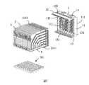
請參圖1及圖2所示,本發明揭示了一種背板連接器組件,其包括第一背板連接器100、與前述第一背板連接器100相配合的第二背板連接器200、與前述第一背板連接器100安裝於一起的第一電路板301以及與前述第二背板連接器200安裝於一起的第二電路板302。於本發明圖示的實施方式中,前述第一背板連接器100與前述第二背板連接器200以相正交的方式插接,前述第一電路板301垂直於前述第二電路板302。Please refer to Figures 1 and 2, the present invention discloses a backplane connector assembly, which includes a
請參照圖3及圖4所示,前述第一背板連接器100包括殼體1、安裝於前述殼體1的複數端子模組2、固持於前述複數端子模組2的後端的固持片3以及固持於前述複數端子模組2的底端的固持塊4。Please refer to FIG. 3 and FIG. 4, the
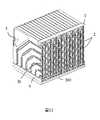
請參照圖5及圖6所示,前述殼體1由絕緣材料製成,其包括本體部11、自前述本體部11的一側向後延伸的第一壁部12以及自前述本體部11的另一相對側向後延伸的第二壁部13。前述本體部11設有對接面111以及貫穿前述對接面111的複數端子收容槽112。於本發明圖示的實施方式中,前述端子收容槽112沿上下方向排列成多排,其中相鄰的兩排端子收容槽112沿左右方向錯開佈置,即相鄰的兩排端子收容槽112中對應位置處的端子收容槽112沿上下方向不對齊。前述第一壁部12設有複數第一插槽121以及與前述第一插槽121相連通的第一鎖扣槽122。前述第二壁部13設有複數第二插槽131以及與前述第二插槽131相連通的第二鎖扣槽132。前述第一鎖扣槽122與前述第二鎖扣槽132分別向外貫穿前述第一壁部12與前述第二壁部13,用以鎖扣前述端子模組2,防止前述端子模組2脫離前述殼體1。相互對齊的前述第一插槽121、前述第二插槽131以及前述端子收容槽112共同用以收容一個端子模組2。Please refer to Figures 5 and 6, the
又,請參照圖6所示,前述殼體1還設有分別自前述第一壁部12以及前述第二壁部13向前延伸且凸出前述對接面111的複數定位凸起14。前述定位凸起14設有位於其末端的導引斜面141。Also, referring to FIG. 6, the
請參照圖7至圖9所示,前述端子模組2包括絕緣支架21、固定於前述絕緣支架21的複數導電端子22、固定於前述絕緣支架21的一側的第一金屬屏蔽片23以及固定於前述絕緣支架21的另一相對側的第二金屬屏蔽片24。Referring to FIGS. 7-9, the
請參照圖10所示,前述絕緣支架21大致呈框體狀,其包括後壁211、與前述後壁211相對的前壁212、連接前述後壁211的一端與前述前壁212的一端的頂壁213、連接前述後壁211的另一端與前述前壁212的另一端的底壁214、以及複數連接壁215。前述連接壁215能夠對框體產生加強結構強度的作用。前述後壁211設有向後凸出且間隔設置的第一凸塊2111以及第二凸塊2112。前述第一凸塊2111與前述第二凸塊2112對齊設置。前述第一凸塊2111設有第一收縮部2113,前述第二凸塊2112設有第二收縮部2114。於本發明圖示的實施方式中,前述絕緣支架21設有鏤空部210,前述連接壁215包括連接前述頂壁213與前述底壁214的第一連接壁2151以及連接前述後壁211與前述底壁214的第二連接壁2152。前述第一連接壁2151與前述第二連接壁2152暴露於前述鏤空部210中。前述頂壁213設有用以插入前述第一鎖扣槽122中的第一鎖扣凸起2131,前述底壁214設有用以插入前述第二鎖扣槽132中的第二鎖扣凸起2141。Please refer to FIG. 10, the insulating
前述絕緣支架21還設有用以固定前述第一金屬屏蔽片23以及前述第二金屬屏蔽片24的複數凸柱216。於本發明圖示的實施方式中,前述凸柱216設置於前述底壁214、第一連接壁2151、第二連接壁2152以及前壁212上。由於前述第一金屬屏蔽片23以及前述第二金屬屏蔽片24分別位於前述絕緣支架21的兩側,前述凸柱216包括第一凸柱2161以及第二凸柱2162,其中前述第一凸柱2161與前述第二凸柱2162分別位於前述絕緣支架21的相反兩面,俾與前述第一金屬屏蔽片23以及前述第二金屬屏蔽片24相固定且定位。The insulating
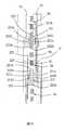
請參照圖10所示,從結構上看,每一組導電端子22包括接觸部221、尾部222以及連接前述接觸部221與前述尾部222的連接部223。部分前述接觸部221用以與第二背板連接器200電性連接,前述尾部222用以安裝於第一電路板301。於本發明圖示的實施方式中,前述接觸部221大致垂直於前述尾部222,前述連接部223呈曲線狀。Referring to FIG. 10, from a structural point of view, each set of
從功能上看,每一組導電端子22包括複數第一接地端子G1、複數第二接地端子G2以及複數訊號端子S1。於本發明圖示的實施方式中,相鄰的兩個訊號端子S1組成一對差分訊號端子,且每一對差分訊號端子位於一個第一接地端子G1與一個第二接地端子G2之間,即每一組導電端子22呈G1-S1-S1-G2的排列方式,這種排列方式有利於提高訊號傳輸的品質。前述差分訊號端子為窄邊耦合或者寬邊耦合。前述第一接地端子G1與前述第二接地端子G2的寬度大於它們之間的訊號端子S1的寬度,從而有利於增加屏蔽面積,改善屏蔽效果。From a functional point of view, each group of
於本發明圖示的實施方式中,前述導電端子22的連接部223嵌入成型於前述絕緣支架21。前述訊號端子S1的連接部223設有埋入前述絕緣支架21中的收窄部2230,俾調節前述訊號端子S1的阻抗,實現阻抗匹配。於本發明圖示的實施方式中,前述訊號端子S1的接觸部221大致呈針狀,前述第一接地端子G1與前述第二接地端子G2的接觸部221大致呈矩型。前述訊號端子S1的接觸部221與前述導電端子22的連接部223均共面,即位於第一平面(例如水平面)內。需要說明的是,本發明中所使用的技術術語“共面”旨於表明相關元件之間係實質平齊的,其包括由於製造公差所造成的不完全共面的情形。然,於本發明圖示的實施方式中,前述第一接地端子G1設有連接其接觸部221與其尾部222的第一扭轉部2241,從而使前述第一接地端子G1的接觸部221位於垂直於前述第一平面的第二平面(例如豎直面)內。前述第二接地端子G2設有連接其接觸部221與其尾部222的第二扭轉部2242,從而使前述第二接地端子G2的接觸部221也位於垂直於前述第一平面的第二平面(例如豎直面)內。前述第一接地端子G1的接觸部221與前述第二接地端子G2的接觸部221相互平行。前述第一接地端子G1與前述第二接地端子G2的連接部223還設有靠近其尾部222的開槽2231。前述開槽2231貫穿前述第一接地端子G1與前述第二接地端子G2的連接部223的底邊緣,使前述第一接地端子G1與前述第二接地端子G2的連接部223分為第一端部2232以及第二端部2233。In the illustrated embodiment of the present invention, the connecting portion of the aforementioned conductive terminal 22223 is insert-molded on the aforementioned insulating
於本發明圖示的實施方式中,前述第一金屬屏蔽片23與前述第二金屬屏蔽片24對稱設置於前述絕緣支架21的兩側。請參圖8、圖9及圖11所示,前述第一金屬屏蔽片23包括第一主體部231以及自前述第一主體部231延伸的第一延伸部232。前述第一主體部231位於前述導電端子22的連接部223的一側,前述第一延伸部232位於前述導電端子22的接觸部221的一側。於本發明圖示的實施方式中,前述第一延伸部232與前述第一主體部231位於不同的平面內,其中前述第一延伸部232比前述第一主體部231更遠離前述第二金屬屏蔽片24。前述第一主體部231設有與複數第一凸柱2161相配合的複數第一安裝孔2311,並藉由焊接將第一凸柱2161固定且定位於第一安裝孔2311,從而實現前述第一金屬屏蔽片23與前述絕緣支架21的固定與定位。前述第一主體部231設有複數凸肋233,前述凸肋233包括向前述第一接地端子G1凸出的第一凸肋2331以及向前述第二接地端子G2凸出的第二凸肋2332。前述第一凸肋2331沿前述第一接地端子G1的連接部223的延伸方向設置。前述第二凸肋2332沿前述第二接地端子G2的連接部223的延伸方向設置。於本發明圖示的實施方式中,前述第一凸肋2331與前述第二凸肋2332係由衝壓前述第一主體部231而形成。前述第一凸肋2331與前述第二凸肋2332向前述第二金屬屏蔽片24的方向凸出。前述第一凸肋2331與前述第二凸肋2332沿前述第一接地端子G1與前述第二接地端子G2的連接部223的延伸方向不連續地設置,實現多點接觸,俾提高第一金屬屏蔽片23與第一接地端子G1以及第二接地端子G2的接觸可靠性。於本發明圖示的實施方式中,請參照圖16所示,前述第一凸肋2331的壁厚、前述第二凸肋2332的壁厚以及前述第一主體部231位於前述第一凸肋2331與前述第二凸肋2332之間的部分的壁厚相同。In the illustrated embodiment of the present invention, the first
前述第一延伸部232設有向前述第一接地端子G1的接觸部221凸出的第一凸起2321、向前述第二接地端子G2的接觸部221凸出的第二凸起2322、以及位於相鄰的第一凸起2321與第二凸起2322之間的第一彈片2323。前述第一彈片2323向前述第一主體部231的方向延伸,前述第一彈片2323設有弧型接觸部2324。於本發明圖示的實施方式中,前述第一延伸部232還設有位於前述第一彈片2323的兩端的兩個第一凸片2325,前述第一凸片2325與前述第一彈片2323的延伸方向相反,前述第一凸片2325向外凸出俾與相鄰的端子模組2相接觸,俾提高屏蔽效果。於本發明圖示的實施方式中,請參照圖18所示,前述第一凸起2321的壁厚、前述第二凸起2322的壁厚以及前述第一延伸部232位於前述第一凸起2321與前述第二凸起2322之間的部分的壁厚相同。The
又,前述第一主體部231還設有自其底邊緣進一步向下延伸的複數第一凸出片2312以及位於相鄰兩個第一凸出片2312之間的連接片2313。藉由設置前述第一凸出片2312能夠延長屏蔽長度,提高對前述訊號端子S1的屏蔽效果。於本發明圖示的實施方式中,前述連接片2313係自前述第一主體部231衝壓而成,前述連接片2313橫跨前述開槽2231,俾將同一個第一接地端子G1的第一端部2232與第二端部2233的一側連接起來,提高屏蔽效果;又,前述連接片2313也得將同一個第二接地端子G2的第一端部2232與第二端部2233的一側連接起來,提高屏蔽效果。類似地,請參圖8、圖9及圖12所示,前述第二金屬屏蔽片24包括第二主體部241以及自前述第二主體部241延伸的第二延伸部242。前述第二主體部241位於前述導電端子22的連接部223的另一相對側,前述第二延伸部242位於前述導電端子22的接觸部221的另一相對側。於本發明圖示的實施方式中,前述第二延伸部242與前述第二主體部241位於不同的平面內,其中前述第二延伸部242比前述第二主體部241更遠離前述第一金屬屏蔽片23。前述第二主體部241設有與複數第二凸柱2162相配合的複數第二安裝孔2411,並藉由焊接將第二凸柱2162固定且定位於第二安裝孔2411,從而實現前述第二金屬屏蔽片24與前述絕緣支架21的固定與定位。前述第二主體部241設有複數凸肋243,前述凸肋243包括向前述第一接地端子G1凸出的第三凸肋2431以及向前述第二接地端子G2凸出的第四凸肋2432。前述第三凸肋2431沿前述第一接地端子G1的連接部223的延伸方向設置。前述第四凸肋2432沿前述第二接地端子G2的連接部223的延伸方向設置。於本發明圖示的實施方式中,前述第三凸肋2431與前述第四凸肋2432係由衝壓前述第二主體部241而形成。前述第三凸肋2431與前述第四凸肋2432向前述第一金屬屏蔽片23的方向凸出。前述第三凸肋2431與前述第四凸肋2432沿前述第一接地端子G1與前述第二接地端子G2的連接部223的延伸方向不連續地設置,實現多點接觸,俾提高第二金屬屏蔽片24與第一接地端子G1以及第二接地端子G2的接觸可靠性。於本發明圖示的實施方式中,前述第三凸肋2431的壁厚、前述第四凸肋2432的壁厚以及前述第二主體部241位於前述第三凸肋2431與前述第四凸肋2432之間的部分的壁厚相同。於本發明的一種實施方式中,於前述凸肋233以及前述凸肋243的表面上進行焊接,用以將前述凸肋233以及前述凸肋243與前述第一接地端子G1以及前述第二接地端子G2相焊接。例如,於前述第一凸肋2331、前述第二凸肋2332、前述第三凸肋2431以及前述第四凸肋2432的表面上進行焊接,用以將前述第一凸肋2331、前述第二凸肋2332、前述第三凸肋2431以及前述第四凸肋2432與前述第一接地端子G1以及前述第二接地端子G2相焊接,其中焊接方式為點焊、鐳射焊及超聲波焊中的至少一種。In addition, the aforementioned first
前述第二延伸部242設有向前述第一接地端子G1的接觸部221凸出的第三凸起2421、向前述第二接地端子G2的接觸部221凸出的第四凸起2422、以及位於相鄰的第三凸起2421與第四凸起2422之間的第二彈片2423。前述第二彈片2423向前述第二主體部241的方向延伸,前述第二彈片2423設有弧型接觸部2424。於本發明圖示的實施方式中,前述第二延伸部242還設有位於前述第二彈片2423的兩端的兩個第二凸片2425,前述第二凸片2425與前述第二彈片2423的延伸方向相反,前述第二凸片2425向外凸出俾與相鄰的端子模組2相接觸,俾提高屏蔽效果。於本發明圖示的實施方式中,前述第三凸起2421的壁厚、前述第四凸起2422的壁厚以及前述第二延伸部242位於前述第三凸起2421與前述第四凸起2422之間的部分的壁厚相同。The
又,前述第二主體部241還設有自其底邊緣進一步向下延伸的複數第二凸出片2412以及位於相鄰兩個第二凸出片2412之間的連接片2413。藉由設置前述第二凸出片2412能夠延長屏蔽長度,提高對前述訊號端子S1的屏蔽效果。於本發明圖示的實施方式中,前述連接片2413係自前述第二主體部241衝壓而成,前述連接片2413橫跨前述開槽2231,俾將同一個第一接地端子G1的第一端部2232與第二端部2233的另一相對側連接起來,提高屏蔽效果;又,前述連接片2413也得將同一個第二接地端子G2的第一端部2232與第二端部2233的另一相對側連接起來,提高屏蔽效果。請參照圖13至圖16所示,於本發明圖示的實施方式中,前述第一接地端子G1的接觸部221與連接部223均設有第一寬面221a以及垂直於前述第一寬面221a的第一窄面221b。前述第二接地端子G2的接觸部221與連接部223均設有第二寬面221c以及垂直於前述第二寬面221c的第二窄面221d。每一對差分訊號端子的連接部223位於其兩側的第一接地端子G1的第一窄面221b以及第二接地端子G2的第二窄面221d之間。每一對差分訊號端子的接觸部221位於其兩側的第一接地端子G1的第一寬面221a以及第二接地端子G2的第二寬面221c之間。於本發明圖示的實施方式中,前述第一寬面221a與前述第二寬面221c的寬度大於前述訊號端子S1的接觸部221的寬度,從而能夠給前述訊號端子S1的接觸部221提供更好的屏蔽。In addition, the aforementioned second
請參圖14所示,於前述導電端子22的連接部223的長度上,前述第一金屬屏蔽片23的第一凸肋2331以及前述第二金屬屏蔽片24的第三凸肋2431分別與第一接地端子G1的連接部223的兩相對側面接觸,從而於每一對差分訊號端子的連接部223的外周形成了環繞的屏蔽腔26。於本發明圖示的實施方式中,前述第一凸肋2331與前述第三凸肋2431分別與前述第一接地端子G1的連接部223的第一寬面221a相接觸,前述第二凸肋2332與前述第四凸肋2432分別與前述第二接地端子G2的連接部223的第二寬面221c相接觸。於本發明圖示的實施方式中,前述屏蔽腔26係由前述第一主體部231、前述第二主體部241、前述第一接地端子G1以及前述第二接地端子G2共同形成。前述第一接地端子G1的連接部223設有延伸入前述屏蔽腔26中的第一凸片部2234,前述第二接地端子G2的連接部223設有延伸入前述屏蔽腔26中的第二凸片部2235,前述差分訊號端子的連接部223位於前述第一凸片部2234與前述第二凸片部2235之間。前述屏蔽腔26為複數且沿著每一組前述導電端子22的排佈方向連續設置,其中相鄰的兩個屏蔽腔26共用一個第一接地端子G1或者共用一個第二接地端子G2。且該共用的第一接地端子G1一部分凸伸入一個屏蔽腔26,該共用的第一接地端子G1另一部分凸伸入另一個屏蔽腔26。Please refer to FIG. 14, in the length of the connecting
請參照圖18所示,於前述導電端子22的接觸部221的長度上,前述第一金屬屏蔽片23的第一凸起2321與前述第三凸起2421分別與前述第一接地端子G1的接觸部221的兩相對側面相接觸,前述第二凸起2322與前述第四凸起2422分別與前述第二接地端子G2的接觸部221的兩相對側面相接觸。於本發明圖示的實施方式中,前述第一金屬屏蔽片23的第一凸起2321與前述第三凸起2421分別與前述第一接地端子G1的接觸部221的第一窄面221b相接觸,前述第二凸起2322與前述第四凸起2422分別與前述第二接地端子G2的接觸部221的第二窄面221d相接觸。前述第一延伸部232、前述第二延伸部242、前述第一接地端子G1以及前述第二接地端子G2圍成收容前述差分訊號端子的接觸部221的屏蔽腔體27。前述第一彈片2323與前述第二彈片2423延伸入前述屏蔽腔體27內。前述屏蔽腔體27沿著每一組前述導電端子22的層疊方向連續設置,其中相鄰的兩個屏蔽腔體27共用一個第一接地端子G1或者共用一個第二接地端子G2。該共用的第一接地端子G1的接觸部221的一個第一寬面221a暴露於屏蔽腔體27,該共用的第一接地端子G1的接觸部221的另一個第一寬面221a暴露於相鄰的屏蔽腔體27。類似地,該共用的第二接地端子G2的接觸部221的一個第二寬面221c暴露於屏蔽腔體27,該共用的第二接地端子G2的接觸部221的另一個第二寬面221c暴露於相鄰的屏蔽腔體27。Please refer to FIG. 18, in the length of the
於本發明圖示的實施方式中,前述第一背板連接器100的端子模組2有複數,且相鄰的兩個端子模組2的端子佈置係錯開的。相應地,相鄰的兩個端子模組2的相同位置處的屏蔽腔26相互錯開(請參照圖15);相鄰的兩個端子模組2的相同位置處的屏蔽腔體27相互錯開(請參照圖17)。In the illustrated embodiment of the present invention, there are plural
以上實施方式僅用以說明本發明而並非限制本發明所描述的技術方案,對本發明的理解應該以所屬技術領域的技術人員為基礎,儘管本說明書參照前述的實施方式對本發明已進行了詳細的說明,惟,本領域的普通技術人員應當理解,所屬技術領域的技術人員仍然得對本發明進行修改或者等同替換,而一切不脫離本發明的精神和範圍的技術方案及其改進,均應涵蓋於本發明的申請專利範圍內。The above embodiments are only used to illustrate the present invention and not to limit the technical solutions described in the present invention. The understanding of the present invention should be based on those skilled in the art, although the present specification has been described in detail with reference to the foregoing embodiments. Note, however, those of ordinary skill in the art should understand that those skilled in the art still have to modify or equivalently replace the present invention, and all technical solutions and improvements that do not depart from the spirit and scope of the present invention should be covered The invention is within the scope of patent application.
221:接觸部221: contact part
221a:第一寬面221a: The first wide side
221b:第一窄面221b: The first narrow side
221c:第二寬面221c: second wide side
221d:第二窄面221d: second narrow side
23:第一金屬屏蔽片23: The first metal shield
2321:第一凸起2321: first bump
2322:第二凸起2322: second bump
2323:第一彈片2323: first shrapnel
24:第二金屬屏蔽片24: The second metal shield
2421:第三凸起2421: third bump
2422:第四凸起2422: fourth bump
2423:第二彈片2423: second shrapnel
27:屏蔽腔體27: Shielded cavity
G1:第一接地端子G1: The first ground terminal
G2:第二接地端子G2: second ground terminal
S1:訊號端子S1: Signal terminal
Claims (10)
Translated fromChineseApplications Claiming Priority (2)
| Application Number | Priority Date | Filing Date | Title |
|---|---|---|---|
| CN202010567796 | 2020-06-19 | ||
| CN202010567796.4 | 2020-06-19 |
Publications (2)
| Publication Number | Publication Date |
|---|---|
| TW202046583A TW202046583A (en) | 2020-12-16 |
| TWI741743Btrue TWI741743B (en) | 2021-10-01 |
Family
ID=72438191
Family Applications (24)
| Application Number | Title | Priority Date | Filing Date |
|---|---|---|---|
| TW109210447UTWM609292U (en) | 2020-06-19 | 2020-08-12 | Backplane connector |
| TW109210795UTWM603629U (en) | 2020-06-19 | 2020-08-19 | Backplane connector |
| TW109128295ATWI740618B (en) | 2020-06-19 | 2020-08-19 | Backplane connector |
| TW109210794UTWM604507U (en) | 2020-06-19 | 2020-08-19 | Backplane connector |
| TW109128294ATWI741743B (en) | 2020-06-19 | 2020-08-19 | Backplane connector |
| TW109210793UTWM608316U (en) | 2020-06-19 | 2020-08-19 | Backplane connector |
| TW109129936ATWI755837B (en) | 2020-06-19 | 2020-09-01 | Backplane connector assembly |
| TW109211456UTWM607438U (en) | 2020-06-19 | 2020-09-01 | Printed circuit board and backplane connector assembly |
| TW109129938ATWI742831B (en) | 2020-06-19 | 2020-09-01 | Backplane connector |
| TW109215567UTWM611640U (en) | 2020-06-19 | 2020-11-25 | Shielded housing |
| TW110104071ATWI780586B (en) | 2020-06-19 | 2021-02-03 | Backplane connector assembly |
| TW110104066ATWI811627B (en) | 2020-06-19 | 2021-02-03 | Backplane connector |
| TW110104064ATWI763297B (en) | 2020-06-19 | 2021-02-03 | Backplane connector |
| TW110104068ATWI795726B (en) | 2020-06-19 | 2021-02-03 | Backplane connector |
| TW110201355UTWM619773U (en) | 2020-06-19 | 2021-02-03 | Backplane connector |
| TW110202308UTWM616729U (en) | 2020-06-19 | 2021-03-03 | Backplane connector |
| TW110107593ATWI785517B (en) | 2020-06-19 | 2021-03-03 | Backplane connector |
| TW110202309UTWM613652U (en) | 2020-06-19 | 2021-03-03 | Terminal module and backplane connector |
| TW110202307UTWM614360U (en) | 2020-06-19 | 2021-03-03 | Backplane connector |
| TW110117066ATWI801866B (en) | 2020-06-19 | 2021-05-12 | Backplane connector |
| TW110205633UTWM618159U (en) | 2020-06-19 | 2021-05-17 | Terminal module and backplane connector |
| TW110205634UTWM619876U (en) | 2020-06-19 | 2021-05-17 | Terminal module and backplane connector |
| TW110205632UTWM618935U (en) | 2020-06-19 | 2021-05-17 | Terminal module and backplane connector |
| TW110117853ATWI760222B (en) | 2020-06-19 | 2021-05-17 | Backplane connector |
Family Applications Before (4)
| Application Number | Title | Priority Date | Filing Date |
|---|---|---|---|
| TW109210447UTWM609292U (en) | 2020-06-19 | 2020-08-12 | Backplane connector |
| TW109210795UTWM603629U (en) | 2020-06-19 | 2020-08-19 | Backplane connector |
| TW109128295ATWI740618B (en) | 2020-06-19 | 2020-08-19 | Backplane connector |
| TW109210794UTWM604507U (en) | 2020-06-19 | 2020-08-19 | Backplane connector |
Family Applications After (19)
| Application Number | Title | Priority Date | Filing Date |
|---|---|---|---|
| TW109210793UTWM608316U (en) | 2020-06-19 | 2020-08-19 | Backplane connector |
| TW109129936ATWI755837B (en) | 2020-06-19 | 2020-09-01 | Backplane connector assembly |
| TW109211456UTWM607438U (en) | 2020-06-19 | 2020-09-01 | Printed circuit board and backplane connector assembly |
| TW109129938ATWI742831B (en) | 2020-06-19 | 2020-09-01 | Backplane connector |
| TW109215567UTWM611640U (en) | 2020-06-19 | 2020-11-25 | Shielded housing |
| TW110104071ATWI780586B (en) | 2020-06-19 | 2021-02-03 | Backplane connector assembly |
| TW110104066ATWI811627B (en) | 2020-06-19 | 2021-02-03 | Backplane connector |
| TW110104064ATWI763297B (en) | 2020-06-19 | 2021-02-03 | Backplane connector |
| TW110104068ATWI795726B (en) | 2020-06-19 | 2021-02-03 | Backplane connector |
| TW110201355UTWM619773U (en) | 2020-06-19 | 2021-02-03 | Backplane connector |
| TW110202308UTWM616729U (en) | 2020-06-19 | 2021-03-03 | Backplane connector |
| TW110107593ATWI785517B (en) | 2020-06-19 | 2021-03-03 | Backplane connector |
| TW110202309UTWM613652U (en) | 2020-06-19 | 2021-03-03 | Terminal module and backplane connector |
| TW110202307UTWM614360U (en) | 2020-06-19 | 2021-03-03 | Backplane connector |
| TW110117066ATWI801866B (en) | 2020-06-19 | 2021-05-12 | Backplane connector |
| TW110205633UTWM618159U (en) | 2020-06-19 | 2021-05-17 | Terminal module and backplane connector |
| TW110205634UTWM619876U (en) | 2020-06-19 | 2021-05-17 | Terminal module and backplane connector |
| TW110205632UTWM618935U (en) | 2020-06-19 | 2021-05-17 | Terminal module and backplane connector |
| TW110117853ATWI760222B (en) | 2020-06-19 | 2021-05-17 | Backplane connector |
Country Status (3)
| Country | Link |
|---|---|
| US (24) | US11563290B2 (en) |
| CN (30) | CN212849124U (en) |
| TW (24) | TWM609292U (en) |
Families Citing this family (63)
| Publication number | Priority date | Publication date | Assignee | Title |
|---|---|---|---|---|
| WO2019139882A1 (en)* | 2018-01-09 | 2019-07-18 | Molex, Llc | High density receptacle |
| CN212849124U (en) | 2020-06-19 | 2021-03-30 | 东莞立讯技术有限公司 | Back panel connector |
| CN112652906B (en) | 2020-06-19 | 2022-12-02 | 东莞立讯技术有限公司 | Plugging module and cable connector |
| TWI792271B (en) | 2020-06-19 | 2023-02-11 | 大陸商東莞立訊技術有限公司 | Backplane connector assembly |
| USD987574S1 (en)* | 2020-06-30 | 2023-05-30 | Dongguan Luxshare Technologies Co., Ltd | Electrical connector |
| CN112636046B (en)* | 2020-11-30 | 2022-04-22 | 中航光电科技股份有限公司 | Orthogonal Connector Wafers, Orthogonal Connectors, and Connector Assemblies |
| CN112510396B (en)* | 2020-12-01 | 2025-06-27 | 温州意华接插件股份有限公司 | Terminal assembly and electrical connector |
| CN114665330B (en)* | 2020-12-22 | 2023-01-06 | 华为技术有限公司 | A connector, function board and board-level structure |
| CN112736524B (en) | 2020-12-28 | 2022-09-09 | 东莞立讯技术有限公司 | Terminal module and backplane connector |
| CN112636098A (en)* | 2020-12-28 | 2021-04-09 | 深圳市创益通技术股份有限公司 | 5G bent female frame port type high-shielding structure connector and manufacturing method thereof |
| CN112909660B (en)* | 2021-01-20 | 2022-04-22 | 中航光电科技股份有限公司 | Connector assembly |
| CN112909595B (en)* | 2021-01-20 | 2022-05-13 | 中航光电科技股份有限公司 | Shielding plate, terminal module using shielding plate and female terminal connector |
| CN112909661B (en)* | 2021-01-20 | 2023-04-18 | 中航光电科技股份有限公司 | Terminal module and connector using same |
| CN112909663B (en)* | 2021-01-20 | 2022-04-22 | 中航光电科技股份有限公司 | Shielding plate, terminal module using same and connector |
| CN113193407B (en)* | 2021-02-02 | 2022-10-25 | 中山得意电子有限公司 | Electrical connector |
| CN215645331U (en)* | 2021-02-09 | 2022-01-25 | 中航光电科技股份有限公司 | Shielding piece and bent female connector using same |
| CN114628958B (en)* | 2021-02-09 | 2024-04-16 | 中航光电科技股份有限公司 | Differential signal module and differential signal connector |
| CN113036541B (en)* | 2021-02-25 | 2023-03-31 | 中山得意电子有限公司 | Electrical module |
| CN113193398B (en)* | 2021-04-23 | 2022-03-29 | 中航光电科技股份有限公司 | A shielding contact structure, a female connector and a connector assembly |
| CN115347423B (en)* | 2021-05-13 | 2025-09-16 | 泰科电子(上海)有限公司 | Electric connector assembly |
| TWI816126B (en)* | 2021-05-17 | 2023-09-21 | 佳必琪國際股份有限公司 | Electrical connector |
| CN113488815B (en)* | 2021-08-13 | 2025-06-27 | 四川永贵科技有限公司 | Shielding plate, sheet body, female connector and connector assembly |
| CN113314895A (en)* | 2021-06-03 | 2021-08-27 | 四川永贵科技有限公司 | High-speed backplane connector and connector system |
| EP4099518A1 (en) | 2021-06-03 | 2022-12-07 | Sichuan Yonggui Science and Technology Co., Ltd | Shielding plate, terminal module, high-speed backplane connector, and connector system |
| CN215816681U (en)* | 2021-06-04 | 2022-02-11 | 华为技术有限公司 | Connector and electronic device |
| CN113437589B (en)* | 2021-07-16 | 2025-08-19 | 中航光电科技股份有限公司 | Connector with shielding shell |
| CN113571973B (en)* | 2021-07-21 | 2024-03-19 | 中航光电科技股份有限公司 | Terminal module and high-speed connector using the same |
| CN113904179B (en) | 2021-08-16 | 2023-07-11 | 东莞立讯技术有限公司 | Butt-joint terminal module, butt-joint backboard connector and backboard connector assembly |
| CN113889785B (en)* | 2021-08-16 | 2023-07-11 | 东莞立讯技术有限公司 | Terminal module and back board connector |
| JP2023028570A (en)* | 2021-08-19 | 2023-03-03 | イリソ電子工業株式会社 | Connector and connector set |
| CN113871973A (en)* | 2021-10-18 | 2021-12-31 | 武汉市格力浦电子有限公司 | High-speed connector with low crosstalk |
| CN116111402A (en)* | 2021-11-10 | 2023-05-12 | 东莞富强电子有限公司 | High-speed connector |
| CN114300914B (en)* | 2021-11-26 | 2024-06-11 | 深圳市深科达智能装备股份有限公司 | Plug-in device, system and control method |
| CN116191132A (en)* | 2021-11-26 | 2023-05-30 | 华为技术有限公司 | Receptacle Connectors, Male Connectors and Connector Assemblies |
| CN114389073B (en) | 2022-01-11 | 2023-09-19 | 东莞立讯技术有限公司 | Electrical connectors and components |
| CN114421240B (en)* | 2022-01-26 | 2024-04-30 | 成电智连(成都)科技有限公司 | Shielding element and electric connector |
| CN114421241B (en)* | 2022-01-26 | 2024-04-30 | 成电智连(成都)科技有限公司 | Electric connector and electric connector assembly |
| CN114639979B (en)* | 2022-02-18 | 2024-05-17 | 鹤山市得润电子科技有限公司 | Connector, connector module and electronic device |
| CN114498205A (en)* | 2022-03-10 | 2022-05-13 | 深圳市西点精工技术有限公司 | Back panel connector |
| CN114927894B (en) | 2022-06-10 | 2024-11-08 | 东莞立讯技术有限公司 | Electrical connector |
| CN115021033B (en)* | 2022-06-23 | 2024-05-24 | 四川华丰科技股份有限公司 | Connector with a plurality of connectors |
| CN115133354B (en)* | 2022-07-07 | 2025-08-12 | 中航光电科技股份有限公司 | Shielding structure and electric connector using same |
| CN119547280A (en)* | 2022-08-11 | 2025-02-28 | 莫列斯有限公司 | Connector assembly with U-shaped shield and ground plate |
| CN115296091B (en)* | 2022-08-29 | 2025-07-01 | 深圳市西点精工技术有限公司 | Shielding sheet, communication module and backplane connector socket |
| CN115832740A (en)* | 2022-10-31 | 2023-03-21 | 立讯精密工业股份有限公司 | electrical connector |
| CN115986501A (en)* | 2022-12-13 | 2023-04-18 | 东莞立讯技术有限公司 | Cable connectors and electrical connectors |
| TWI886523B (en)* | 2023-07-26 | 2025-06-11 | 大陸商東莞立訊技術有限公司 | Backplane connector |
| CN117199938A (en)* | 2023-08-10 | 2023-12-08 | 东莞立讯技术有限公司 | Electric connector and assembly thereof |
| CN117175259A (en)* | 2023-09-08 | 2023-12-05 | 中航光电科技股份有限公司 | Positioning buckle plate for connector and connector |
| CN119601998A (en)* | 2023-09-11 | 2025-03-11 | 东莞立讯技术有限公司 | Electrical connector and connector assembly |
| CN117317714B (en)* | 2023-09-28 | 2024-05-31 | 东莞立讯技术有限公司 | Electrical connector |
| CN119726264A (en)* | 2023-09-28 | 2025-03-28 | 中航光电科技股份有限公司 | A connector |
| CN119726263A (en)* | 2023-09-28 | 2025-03-28 | 中航光电科技股份有限公司 | A connector plug-in end common ground structure and connector |
| CN117317713B (en)* | 2023-09-28 | 2024-08-20 | 东莞立讯技术有限公司 | Electric connector |
| CN117317712B (en)* | 2023-09-28 | 2024-05-31 | 东莞立讯技术有限公司 | Electric connector |
| CN117320258B (en)* | 2023-09-28 | 2024-05-31 | 东莞立讯技术有限公司 | Circuit board and connector assembly |
| CN118412713A (en)* | 2023-09-28 | 2024-07-30 | 东莞立讯技术有限公司 | Electrical connector |
| WO2025113219A1 (en)* | 2023-11-28 | 2025-06-05 | 深圳市长盈精密技术股份有限公司 | Terminal group |
| CN119726188A (en)* | 2024-10-09 | 2025-03-28 | 中航光电科技股份有限公司 | A high-speed backplane connector |
| CN119742629A (en)* | 2024-11-20 | 2025-04-01 | 中航光电科技股份有限公司 | High-speed cable assemblies and connectors |
| CN119742628A (en)* | 2024-11-20 | 2025-04-01 | 中航光电科技股份有限公司 | High-speed cable assemblies and connectors |
| CN119812858A (en)* | 2024-11-29 | 2025-04-11 | 中航光电科技股份有限公司 | Straight connector |
| CN119965597B (en)* | 2025-04-09 | 2025-07-29 | 温州意华接插件股份有限公司 | High-speed electric connector and assembly process thereof |
Citations (4)
| Publication number | Priority date | Publication date | Assignee | Title |
|---|---|---|---|---|
| CN104396095A (en)* | 2012-07-18 | 2015-03-04 | 泰科电子公司 | Plug connectors for electrical connector systems |
| US20180166828A1 (en)* | 2004-09-30 | 2018-06-14 | Amphenol Corporation | High speed, high density electrical connector |
| TW201841440A (en)* | 2017-01-27 | 2018-11-16 | 美商太谷康奈特提威提公司 | Shielding structure for a contact module |
| TWM585436U (en)* | 2019-05-13 | 2019-10-21 | 大陸商慶虹電子(蘇州)有限公司 | Female connector and transmission piece thereof |
Family Cites Families (174)
| Publication number | Priority date | Publication date | Assignee | Title |
|---|---|---|---|---|
| US4601527A (en)* | 1985-01-18 | 1986-07-22 | E. I. Du Pont De Nemours And Company | Shielded header and cable assembly |
| ES2070283T3 (en)* | 1989-10-10 | 1995-06-01 | Whitaker Corp | CONTRAPLANE CONNECTOR WITH ADAPTED IMPEDANCES. |
| GB8928777D0 (en)* | 1989-12-20 | 1990-02-28 | Amp Holland | Sheilded backplane connector |
| GB9205088D0 (en)* | 1992-03-09 | 1992-04-22 | Amp Holland | Shielded back plane connector |
| GB9205087D0 (en)* | 1992-03-09 | 1992-04-22 | Amp Holland | Sheilded back plane connector |
| DE69519226T2 (en) | 1995-07-03 | 2001-08-23 | Berg Electronics Manufacturing B.V., S'-Hertogenbosch | Connector with integrated printed circuit board |
| US5664968A (en)* | 1996-03-29 | 1997-09-09 | The Whitaker Corporation | Connector assembly with shielded modules |
| US5795191A (en)* | 1996-09-11 | 1998-08-18 | Preputnick; George | Connector assembly with shielded modules and method of making same |
| US5993259A (en)* | 1997-02-07 | 1999-11-30 | Teradyne, Inc. | High speed, high density electrical connector |
| AU9757598A (en)* | 1997-11-19 | 1999-06-07 | Whitaker Corporation, The | Shielded electrical connector |
| US5980325A (en)* | 1998-07-30 | 1999-11-09 | Berg Technology, Inc. | Micro miniature electrical connector and method of manufacture |
| US6116926A (en)* | 1999-04-21 | 2000-09-12 | Berg Technology, Inc. | Connector for electrical isolation in a condensed area |
| NL1013741C2 (en)* | 1999-12-03 | 2001-06-06 | Fci S Hertogenbosch B V | Shielded connector assembly. |
| US6347962B1 (en)* | 2001-01-30 | 2002-02-19 | Tyco Electronics Corporation | Connector assembly with multi-contact ground shields |
| US6435914B1 (en)* | 2001-06-27 | 2002-08-20 | Hon Hai Precision Ind. Co., Ltd. | Electrical connector having improved shielding means |
| DE10157582A1 (en) | 2001-11-23 | 2003-06-05 | Alstom Switzerland Ltd | Dynamoelectric machine with wedged winding bars |
| US6979215B2 (en) | 2001-11-28 | 2005-12-27 | Molex Incorporated | High-density connector assembly with flexural capabilities |
| CN100544123C (en)* | 2001-11-28 | 2009-09-23 | 莫莱克斯公司 | High-density connector assembly with improved mating capability |
| US6899566B2 (en)* | 2002-01-28 | 2005-05-31 | Erni Elektroapparate Gmbh | Connector assembly interface for L-shaped ground shields and differential contact pairs |
| US6641438B1 (en)* | 2002-06-07 | 2003-11-04 | Hon Hai Precision Ind. Co., Ltd. | High speed, high density backplane connector |
| CN2571029Y (en) | 2002-09-03 | 2003-09-03 | 蔡周旋 | electrical connector |
| US6705893B1 (en) | 2002-09-04 | 2004-03-16 | Hon Hai Precision Ind. Co., Ltd. | Low profile cable connector assembly with multi-pitch contacts |
| CN100524954C (en)* | 2002-12-04 | 2009-08-05 | 莫莱克斯公司 | High density connector assembly with leakage grounding structure |
| US6955565B2 (en) | 2002-12-30 | 2005-10-18 | Molex Incorporated | Cable connector with shielded termination area |
| JP3909769B2 (en)* | 2004-01-09 | 2007-04-25 | 日本航空電子工業株式会社 | connector |
| CN2682605Y (en)* | 2004-01-12 | 2005-03-02 | 上海莫仕连接器有限公司 | Stack type electric connector |
| US7494379B2 (en)* | 2005-09-06 | 2009-02-24 | Amphenol Corporation | Connector with reference conductor contact |
| CN2932730Y (en)* | 2006-07-14 | 2007-08-08 | 富士康(昆山)电脑接插件有限公司 | Electrical connector with shielded housing |
| CN101779340B (en)* | 2007-06-20 | 2013-02-20 | 莫列斯公司 | Impedance control in connector mounting areas |
| CN101330172B (en)* | 2007-06-22 | 2010-09-08 | 贵州航天电器股份有限公司 | High speed high-density connector with modular structure for back board |
| CN101335409B (en)* | 2007-06-29 | 2011-04-27 | 贵州航天电器股份有限公司 | Backing plate connector having circuit board |
| US7445471B1 (en)* | 2007-07-13 | 2008-11-04 | 3M Innovative Properties Company | Electrical connector assembly with carrier |
| JP4399482B2 (en) | 2007-07-25 | 2010-01-13 | フェトン株式会社 | Wire Harness |
| CN201142392Y (en)* | 2007-11-12 | 2008-10-29 | 富士康(昆山)电脑接插件有限公司 | electrical connector |
| CN101459299B (en)* | 2007-12-11 | 2010-11-17 | 富士康(昆山)电脑接插件有限公司 | Electric connector |
| JP4521834B2 (en)* | 2008-01-17 | 2010-08-11 | 日本航空電子工業株式会社 | connector |
| CN101527409B (en)* | 2008-03-05 | 2011-06-15 | 富士康(昆山)电脑接插件有限公司 | Electric connector |
| CN201285845Y (en)* | 2008-08-05 | 2009-08-05 | 富士康(昆山)电脑接插件有限公司 | Electric connector |
| CN101728667B (en)* | 2008-10-16 | 2013-08-14 | 富士康(昆山)电脑接插件有限公司 | Electric connector |
| CN101728867B (en) | 2008-10-20 | 2013-09-04 | 深圳富泰宏精密工业有限公司 | Wireless electric power monitoring system |
| US8167651B2 (en)* | 2008-12-05 | 2012-05-01 | Tyco Electronics Corporation | Electrical connector system |
| US7775802B2 (en) | 2008-12-05 | 2010-08-17 | Tyco Electronics Corporation | Electrical connector system |
| US7976318B2 (en) | 2008-12-05 | 2011-07-12 | Tyco Electronics Corporation | Electrical connector system |
| US8366485B2 (en) | 2009-03-19 | 2013-02-05 | Fci Americas Technology Llc | Electrical connector having ribbed ground plate |
| TWI452767B (en)* | 2009-05-18 | 2014-09-11 | Advanced Connectek Inc | High speed backplane connector |
| US7905751B1 (en)* | 2009-09-23 | 2011-03-15 | Tyco Electronics Corporation | Electrical connector module with contacts of a differential pair held in separate chicklets |
| US8267721B2 (en)* | 2009-10-28 | 2012-09-18 | Fci Americas Technology Llc | Electrical connector having ground plates and ground coupling bar |
| CN102725919B (en)* | 2009-12-30 | 2015-07-08 | Fci公司 | Electrical connector with impedance tuning ribs |
| US20130203273A1 (en)* | 2010-02-02 | 2013-08-08 | Hsio Technologies, Llc | High speed backplane connector |
| US8371876B2 (en)* | 2010-02-24 | 2013-02-12 | Tyco Electronics Corporation | Increased density connector system |
| US7963776B1 (en)* | 2010-03-23 | 2011-06-21 | Tyco Electronics Corporation | Electrical connector assembly having direct connection terminals |
| CN102088148B (en)* | 2010-06-24 | 2013-07-03 | 航天时代电子技术股份有限公司 | Connector socket capable of protecting jack terminal |
| CN203288874U (en) | 2010-10-13 | 2013-11-13 | 3M创新有限公司 | Electrical connector assembly and system |
| CN102468562A (en) | 2010-11-05 | 2012-05-23 | 富士康(昆山)电脑接插件有限公司 | Cable connector assembly |
| CN102694308B (en)* | 2011-03-22 | 2014-09-24 | 富士康(昆山)电脑接插件有限公司 | electrical connector |
| CN103548215B (en)* | 2011-05-27 | 2017-07-04 | Fci公司 | Electrical connector assembly, tool for mating with the same and method for assembling the connector |
| US8465323B2 (en)* | 2011-10-11 | 2013-06-18 | Tyco Electronics Corporation | Electrical connector with interface grounding feature |
| TWM461166U (en)* | 2011-10-12 | 2013-09-01 | Molex Inc | Connector and connector system |
| US8690604B2 (en)* | 2011-10-19 | 2014-04-08 | Tyco Electronics Corporation | Receptacle assembly |
| CN202395246U (en)* | 2011-11-23 | 2012-08-22 | 广迎工业股份有限公司 | Improved structure of USB mother seat board end connector |
| US8845365B2 (en)* | 2011-12-08 | 2014-09-30 | Tyco Electronics Corporation | Cable header connector |
| US8449329B1 (en) | 2011-12-08 | 2013-05-28 | Tyco Electronics Corporation | Cable header connector having cable subassemblies with ground shields connected to a metal holder |
| CN104093668B (en) | 2012-01-19 | 2016-03-02 | 朗盛德国有限责任公司 | Subchloride-LiPF 6 |
| CN103247918B (en) | 2012-02-11 | 2015-11-25 | 富士康(昆山)电脑接插件有限公司 | Micro coaxial cable connector assembly |
| CN103296546B (en)* | 2012-02-22 | 2015-11-25 | 富士康(昆山)电脑接插件有限公司 | Electric coupler component |
| US8961228B2 (en)* | 2012-02-29 | 2015-02-24 | Tyco Electronics Corporation | Electrical connector having shielded differential pairs |
| US9257778B2 (en) | 2012-04-13 | 2016-02-09 | Fci Americas Technology | High speed electrical connector |
| US8556657B1 (en)* | 2012-05-25 | 2013-10-15 | Tyco Electronics Corporation | Electrical connector having split footprint |
| CN103579835B (en)* | 2012-07-27 | 2015-08-19 | 立讯精密工业(昆山)有限公司 | Electric connector |
| US8888533B2 (en) | 2012-08-15 | 2014-11-18 | Tyco Electronics Corporation | Cable header connector |
| CN109004398B (en)* | 2012-08-27 | 2021-09-07 | 安费诺富加宜(亚洲)私人有限公司 | High speed electrical connector |
| WO2014059040A1 (en)* | 2012-10-10 | 2014-04-17 | Amphenol Corporation | Direct connect orthogonal connection systems |
| CN102969621B (en)* | 2012-11-07 | 2016-03-23 | 中航光电科技股份有限公司 | Differential contact elements module and use differential connector and the connector assembly of this module |
| WO2014099331A1 (en) | 2012-12-17 | 2014-06-26 | 3M Innovative Properties Company | Connector assembly |
| TW201429075A (en) | 2013-01-14 | 2014-07-16 | Chief Land Electronic Co Ltd | Electrical connector and terminal cluster thereof |
| US8888530B2 (en)* | 2013-02-26 | 2014-11-18 | Tyco Electronics Corporation | Grounding structures for contact modules of connector assemblies |
| CN104022402B (en)* | 2013-03-01 | 2017-02-08 | 富士康(昆山)电脑接插件有限公司 | Electric connector |
| CN103151650B (en)* | 2013-03-06 | 2015-04-29 | 华为机器有限公司 | Signal connector |
| CN104037551B (en)* | 2013-03-06 | 2016-08-17 | 华为技术有限公司 | Communication equipment back plate adapter and communication equipment |
| JP6127199B2 (en) | 2013-03-13 | 2017-05-10 | モレックス エルエルシー | Integrated signal-to-element and connector using the same |
| CN203218619U (en)* | 2013-03-26 | 2013-09-25 | 连展科技电子(昆山)有限公司 | Socket electrical connector inhabiting crosstalk |
| EP2811589B1 (en)* | 2013-06-05 | 2016-08-24 | Tyco Electronics Corporation | Electrical connector and circuit board assembly including the same |
| US9350126B2 (en)* | 2013-07-19 | 2016-05-24 | Foxconn Interconnect Technology Limited | Electrical connector having a receptacle with a shielding plate and a mating plug with metallic side arms |
| US9017103B2 (en)* | 2013-07-23 | 2015-04-28 | Tyco Electronics Corporation | Modular connector assembly |
| US9548570B2 (en)* | 2013-07-23 | 2017-01-17 | Molex, Llc | Direct backplane connector |
| WO2015056341A1 (en) | 2013-10-18 | 2015-04-23 | 三菱電機株式会社 | Dc power source device, motor drive device, air conditioner, and refrigerator |
| CN203589266U (en) | 2013-12-06 | 2014-05-07 | 泰科电子(上海)有限公司 | Split type conductive terminal structure and connector |
| CN104779487A (en)* | 2014-01-09 | 2015-07-15 | 富士康(昆山)电脑接插件有限公司 | Electric connector |
| CN204088689U (en)* | 2014-02-21 | 2015-01-07 | 番禺得意精密电子工业有限公司 | Electric connector |
| CN203800269U (en)* | 2014-04-10 | 2014-08-27 | 康联精密机电(深圳)有限公司 | I/O high-frequency connector |
| CN103972722A (en)* | 2014-04-21 | 2014-08-06 | 连展科技电子(昆山)有限公司 | Electrical connector structure capable of restraining swing of signal modules |
| TWI504082B (en)* | 2014-04-21 | 2015-10-11 | Advanced Connectek Inc | Socket electrical connector and plug electrical connector |
| CN105470736B (en)* | 2014-08-27 | 2019-08-30 | 富士康(昆山)电脑接插件有限公司 | Electric connector |
| CN105470732B (en)* | 2014-08-27 | 2019-10-08 | 富士康(昆山)电脑接插件有限公司 | Pin connector |
| CN104241975B (en)* | 2014-09-04 | 2017-06-06 | 深圳市正耀科技有限公司 | A kind of connector plug, connector body and its connector combination |
| TW201613203A (en) | 2014-09-29 | 2016-04-01 | Foxconn Interconnect Technology Ltd | Electrical connector assembly and assembling method of the same |
| US9685736B2 (en)* | 2014-11-12 | 2017-06-20 | Amphenol Corporation | Very high speed, high density electrical interconnection system with impedance control in mating region |
| CN105742854B (en)* | 2014-12-08 | 2018-04-06 | 欧品电子(昆山)有限公司 | Backboard socket connector |
| CN204304028U (en)* | 2014-12-08 | 2015-04-29 | 欧品电子(昆山)有限公司 | Backboard socket connector |
| CN104505878A (en) | 2014-12-12 | 2015-04-08 | 国家电网公司 | Portable voltage-stabilizing mobile power supply device |
| US9407045B2 (en)* | 2014-12-16 | 2016-08-02 | Tyco Electronics Corporation | Electrical connector with joined ground shields |
| CN105789987B (en)* | 2014-12-25 | 2019-04-16 | 泰连公司 | Electric connector with ground frame |
| CN104577406B (en) | 2015-02-05 | 2018-04-24 | 深圳市创亿欣精密电子股份有限公司 | SATA composite connectors |
| US9608383B2 (en)* | 2015-04-17 | 2017-03-28 | Amphenol Corporation | High density electrical connector with shield plate louvers |
| CN104810657B (en)* | 2015-04-28 | 2017-05-10 | 昆山全方位电子科技有限公司 | Type-C socket connector |
| US9728903B2 (en) | 2015-04-30 | 2017-08-08 | Molex, Llc | Wafer for electrical connector |
| CN105024230B (en)* | 2015-07-20 | 2017-12-05 | 深圳市长盈精密技术股份有限公司 | Positive anti-plug USB plug |
| TWI648925B (en)* | 2015-12-14 | 2019-01-21 | 莫仕有限公司 | Backplane connector and connector system |
| US9531133B1 (en)* | 2015-12-14 | 2016-12-27 | Tyco Electronics Corporation | Electrical connector having lossy spacers |
| CN105812664A (en) | 2016-03-22 | 2016-07-27 | 广东欧珀移动通信有限公司 | Mobile terminal photographing method and mobile terminal |
| CN105798350B (en) | 2016-04-15 | 2019-01-22 | 安阳师范学院 | An adjustment device that can adjust the drilling position respectively |
| CN105958245B (en) | 2016-06-08 | 2018-10-12 | 欧品电子(昆山)有限公司 | High speed connector component, socket connector and its female terminal |
| US10879651B2 (en)* | 2016-06-18 | 2020-12-29 | Molex, Llc | Selectively shielded connector channel |
| CN205846279U (en)* | 2016-06-30 | 2016-12-28 | 欧品电子(昆山)有限公司 | There is the High speed rear panel socket connector of double-contact difference signal terminal |
| US9748698B1 (en)* | 2016-06-30 | 2017-08-29 | Te Connectivity Corporation | Electrical connector having commoned ground shields |
| CN106207589A (en) | 2016-07-15 | 2016-12-07 | 石庆国 | A kind of socket |
| US10128616B2 (en)* | 2016-07-25 | 2018-11-13 | Te Connectivity Corporation | Electrical connector having commoned ground shields |
| CN106207569B (en)* | 2016-07-29 | 2019-04-19 | 中航光电科技股份有限公司 | High-speed electrical connector and its signal module and method for forming the signal module |
| CN106785533B (en)* | 2016-11-30 | 2019-07-23 | 中航光电科技股份有限公司 | A kind of differential connector and its housing parts |
| CN106058544B (en)* | 2016-08-03 | 2018-11-30 | 欧品电子(昆山)有限公司 | High speed connector component, socket connector and pin connector |
| TWI606645B (en) | 2016-09-10 | 2017-11-21 | 凡甲科技股份有限公司 | Electrical connector |
| JP6784192B2 (en)* | 2017-01-12 | 2020-11-11 | 住友電装株式会社 | Wire harness |
| US9812817B1 (en)* | 2017-01-27 | 2017-11-07 | Te Connectivity Corporation | Electrical connector having a mating connector interface |
| US9985389B1 (en)* | 2017-04-07 | 2018-05-29 | Te Connectivity Corporation | Connector assembly having a pin organizer |
| CN107104329B (en)* | 2017-05-03 | 2019-04-26 | 番禺得意精密电子工业有限公司 | Electric connector combination |
| TWI788394B (en)* | 2017-08-03 | 2023-01-01 | 美商安芬諾股份有限公司 | Cable assembly and method of manufacturing the same |
| CN107585279A (en) | 2017-09-06 | 2018-01-16 | 东莞市亿富隆户外用品有限公司 | Mouthpiece for diving respirator with water drinking function |
| US10431936B2 (en)* | 2017-09-28 | 2019-10-01 | Te Connectivity Corporation | Electrical connector with impedance control members at mating interface |
| CN109586086B (en)* | 2017-09-29 | 2021-03-23 | 中航光电科技股份有限公司 | Differential connector assembly and differential connector thereof |
| CN109599724B (en)* | 2017-09-30 | 2020-09-08 | 中航光电科技股份有限公司 | Shielding piece of backplane connector |
| CN207530119U (en)* | 2017-09-30 | 2018-06-22 | 中航光电科技股份有限公司 | Connector assembly and its back panel connector, differential pair shielding construction |
| CN109841081A (en) | 2017-11-29 | 2019-06-04 | 深圳市微能信息科技有限公司 | A kind of vehicle positioning method and handheld terminal based on Bluetooth technology |
| CN109950721B (en)* | 2017-12-20 | 2020-11-17 | 中航光电科技股份有限公司 | Contact unit, contact assembly comprising same, connector and connector assembly |
| US10790618B2 (en)* | 2018-01-30 | 2020-09-29 | Te Connectivity Corporation | Electrical connector system having a header connector |
| CN110212326B (en)* | 2018-02-28 | 2021-09-03 | 中航光电科技股份有限公司 | Connector assembly and back plate connector and grounding buckle plate thereof |
| CN110247233B (en)* | 2018-03-09 | 2021-12-21 | 泰科电子(上海)有限公司 | Connector with a locking member |
| TWI668927B (en)* | 2018-04-03 | 2019-08-11 | 慶良電子股份有限公司 | Electrical connector and transsmitting wafer thereof |
| CN110459919B (en)* | 2018-06-29 | 2022-01-25 | 中航光电科技股份有限公司 | Differential connector and differential pair shielding structure and shielding buckle plate thereof |
| US10498100B1 (en)* | 2018-07-06 | 2019-12-03 | Tyco Electronics Corporation | Electrical connector assembly having press tabs for seating tool |
| CN110707493B (en)* | 2018-07-10 | 2021-08-31 | 莫列斯有限公司 | Intermediate adapter connector and electric connector combination |
| CN109659725B (en)* | 2018-07-30 | 2020-08-28 | 番禺得意精密电子工业有限公司 | Electrical connector |
| CN110957598B (en)* | 2018-09-27 | 2023-04-28 | 泰连公司 | Electrical connector and electrical connector assembly having mating arrays of signal and ground contacts |
| CN109473805A (en)* | 2018-09-27 | 2019-03-15 | 华为技术有限公司 | A connector and backplane interconnection system |
| CN208955335U (en)* | 2018-10-23 | 2019-06-07 | 温州意华接插件股份有限公司 | Back panel connector |
| CN109390806B (en)* | 2018-12-12 | 2024-10-01 | 四川华丰科技股份有限公司 | Shield, plug connector and connector |
| TWM591270U (en)* | 2018-12-17 | 2020-02-21 | 大陸商歐品電子(昆山)有限公司 | High-speed connector assembly, socket connector and grounding plate |
| CN109546384B (en)* | 2018-12-17 | 2024-02-23 | 欧品电子(昆山)有限公司 | High-speed connector assembly, socket connector and grounding plate |
| CN209056665U (en)* | 2019-01-09 | 2019-07-02 | 四川华丰企业集团有限公司 | Male end signal transmission module with metal shielding board |
| CN109546388B (en)* | 2019-01-18 | 2023-10-10 | 四川华丰科技股份有限公司 | Backboard connector |
| CN111585098B (en)* | 2019-02-19 | 2025-08-19 | 安费诺有限公司 | High-speed connector |
| CN109841981B (en) | 2019-03-22 | 2024-02-23 | 欧品电子(昆山)有限公司 | High-speed backboard connector and bottom cover thereof |
| CN110185448A (en) | 2019-05-19 | 2019-08-30 | 中铁十九局集团矿业投资有限公司 | A kind of ground fracturing and underground blasting control deep orebody rock burst method |
| CN114824953A (en)* | 2019-05-28 | 2022-07-29 | 华为技术有限公司 | signal connector |
| CN209929564U (en)* | 2019-05-30 | 2020-01-10 | 美国莫列斯有限公司 | Connector with a locking member |
| CN110165448A (en)* | 2019-06-06 | 2019-08-23 | 东莞讯滔电子有限公司 | electrical connector |
| CN110190432B (en)* | 2019-06-28 | 2023-12-05 | 东莞立讯技术有限公司 | First terminal group, first terminal module, first connector and connector assembly |
| CN110247223B (en)* | 2019-07-17 | 2024-01-26 | 上海航天科工电器研究院有限公司 | Differential connector with special-shaped conductive structure and manufacturing method thereof |
| CN110323622B (en)* | 2019-07-17 | 2024-07-19 | 上海航天科工电器研究院有限公司 | Radio frequency coaxial connector with special-shaped conductive structure and manufacturing method thereof |
| CN110600943B (en)* | 2019-08-21 | 2021-05-18 | 中航光电科技股份有限公司 | Shielding plate assembly, contact element module and high-speed electric connector |
| CN110544850B (en)* | 2019-09-02 | 2025-01-03 | 深圳万德溙光电科技有限公司 | A high-speed, low-loss connector and interconnection system with reliable elastic contact |
| CN110649407B (en) | 2019-09-02 | 2024-11-26 | 深圳万德溙光电科技有限公司 | A highly elastic, low crosstalk, small space, reliable contact connector |
| TWM593091U (en)* | 2019-10-02 | 2020-04-01 | 大陸商通普康電子(昆山)有限公司 | Connector and transmitting wafer thereof |
| CN110808499B (en)* | 2019-10-12 | 2022-04-05 | 华为机器有限公司 | Male end connector, female end connector, connector assembly and communication equipment |
| CN110718815A (en)* | 2019-11-12 | 2020-01-21 | 深圳市西点精工技术有限公司 | Back panel connector |
| CN110838635A (en)* | 2019-11-14 | 2020-02-25 | 立讯精密工业股份有限公司 | Electrical connector |
| CN110783776B (en)* | 2019-12-04 | 2024-05-07 | 武汉市格力浦电子有限公司 | High-speed signal transmission connector |
| CN113131244B (en)* | 2019-12-31 | 2025-09-16 | 富鼎精密工业(郑州)有限公司 | Electric connector and electric connector assembly |
| CN113131239B (en)* | 2019-12-31 | 2023-08-15 | 富鼎精密工业(郑州)有限公司 | Electric connector |
| CN113131243A (en)* | 2019-12-31 | 2021-07-16 | 富鼎精密工业(郑州)有限公司 | Electrical connector |
| CN111092342B (en)* | 2020-01-20 | 2021-12-07 | 中航光电科技股份有限公司 | Socket of high-speed connector |
| CN111370890B (en)* | 2020-03-06 | 2022-05-03 | 东莞立讯技术有限公司 | Electrical connectors, adapters, and electrical connector assemblies |
| CN111682389B (en) | 2020-05-19 | 2021-06-04 | 国网安徽省电力有限公司电力科学研究院 | A main wire capturing system and a J-type wire clip wiring device using the same |
| CN212849124U (en)* | 2020-06-19 | 2021-03-30 | 东莞立讯技术有限公司 | Back panel connector |
| CN111682360A (en) | 2020-06-24 | 2020-09-18 | 乐清市八达光电科技股份有限公司 | Plug and connector |
- 2020
- 2020-07-22CNCN202021461747.4Upatent/CN212849124U/enactiveActive
- 2020-07-22CNCN202021462818.2Upatent/CN212849125U/enactiveActive
- 2020-07-22CNCN202010709127.6Apatent/CN111682366B/enactiveActive
- 2020-07-22CNCN202021461673.4Upatent/CN212849123U/enactiveActive
- 2020-07-22CNCN202010709180.6Apatent/CN111682367B/enactiveActive
- 2020-07-22CNCN202021462798.9Upatent/CN213151158U/enactiveActive
- 2020-07-22CNCN202021462763.5Upatent/CN213151157U/enactiveActive
- 2020-07-22CNCN202010710463.2Apatent/CN111682369B/enactiveActive
- 2020-07-22CNCN202010710402.6Apatent/CN111682368B/enactiveActive
- 2020-08-04CNCN202021598514.9Upatent/CN213151159U/enactiveActive
- 2020-08-12TWTW109210447Upatent/TWM609292U/enunknown
- 2020-08-17CNCN202021708219.4Upatent/CN212412339U/enactiveActive
- 2020-08-17CNCN202021708192.9Upatent/CN212412338U/enactiveActive
- 2020-08-17CNCN202010822431.1Apatent/CN111864475A/enactivePending
- 2020-08-17CNCN202021709484.4Upatent/CN213151160U/enactiveActive
- 2020-08-17CNCN202010823256.8Apatent/CN111864477B/enactiveActive
- 2020-08-17CNCN202021717656.2Upatent/CN212412340U/enactiveActive
- 2020-08-17CNCN202021709481.0Upatent/CN212849126U/enactiveActive
- 2020-08-17CNCN202010823188.5Apatent/CN111864476A/enactivePending
- 2020-08-17CNCN202010823428.1Apatent/CN111864478B/enactiveActive
- 2020-08-19TWTW109210795Upatent/TWM603629U/enunknown
- 2020-08-19TWTW109128295Apatent/TWI740618B/enactive
- 2020-08-19TWTW109210794Upatent/TWM604507U/enunknown
- 2020-08-19TWTW109128294Apatent/TWI741743B/enactive
- 2020-08-19TWTW109210793Upatent/TWM608316U/enunknown
- 2020-09-01TWTW109129936Apatent/TWI755837B/enactive
- 2020-09-01TWTW109211456Upatent/TWM607438U/enunknown
- 2020-09-01TWTW109129938Apatent/TWI742831B/enactive
- 2020-09-07CNCN202010931721.XApatent/CN111900577B/enactiveActive
- 2020-09-07CNCN202021934671.2Upatent/CN212849127U/enactiveActive
- 2020-09-07CNCN202021934802.7Upatent/CN212849128U/enactiveActive
- 2020-09-07CNCN202021936502.2Upatent/CN213460337U/enactiveActive
- 2020-11-25TWTW109215567Upatent/TWM611640U/enunknown
- 2020-12-28CNCN202023230734.9Upatent/CN213878626U/enactiveActive
- 2020-12-28CNCN202011577310.1Apatent/CN112510442B/enactiveActive
- 2020-12-28CNCN202023230791.7Upatent/CN213878627U/enactiveActive
- 2020-12-28CNCN202023231405.6Upatent/CN213878628U/enactiveActive
- 2021
- 2021-01-12CNCN202110037249.XApatent/CN112864724B/enactiveActive
- 2021-01-12CNCN202110037232.4Apatent/CN113823958B/enactiveActive
- 2021-02-03TWTW110104071Apatent/TWI780586B/enactive
- 2021-02-03TWTW110104066Apatent/TWI811627B/enactive
- 2021-02-03TWTW110104064Apatent/TWI763297B/enactive
- 2021-02-03TWTW110104068Apatent/TWI795726B/enactive
- 2021-02-03TWTW110201355Upatent/TWM619773U/enunknown
- 2021-03-03TWTW110202308Upatent/TWM616729U/enunknown
- 2021-03-03TWTW110107593Apatent/TWI785517B/enactive
- 2021-03-03TWTW110202309Upatent/TWM613652U/enunknown
- 2021-03-03TWTW110202307Upatent/TWM614360U/enunknown
- 2021-03-04CNCN202120475647.5Upatent/CN214798035U/enactiveActive
- 2021-05-12TWTW110117066Apatent/TWI801866B/enactive
- 2021-05-17TWTW110205633Upatent/TWM618159U/enunknown
- 2021-05-17TWTW110205634Upatent/TWM619876U/enunknown
- 2021-05-17TWTW110205632Upatent/TWM618935U/enunknown
- 2021-05-17TWTW110117853Apatent/TWI760222B/enactive
- 2021-05-28USUS17/334,195patent/US11563290B2/enactiveActive
- 2021-05-28USUS17/334,157patent/US11699880B2/enactiveActive
- 2021-05-28USUS17/334,424patent/US11600953B2/enactiveActive
- 2021-05-28USUS17/334,187patent/US11502459B2/enactiveActive
- 2021-05-28USUS17/334,216patent/US11557860B2/enactiveActive
- 2021-05-28USUS17/334,442patent/US11605919B2/enactiveActive
- 2021-05-28USUS17/333,958patent/US11600952B2/enactiveActive
- 2021-05-28USUS17/333,827patent/US11522320B2/enactiveActive
- 2021-05-28USUS17/334,457patent/US11862898B2/enactiveActive
- 2021-05-28USUS17/334,014patent/US11502458B2/enactiveActive
- 2021-05-28USUS17/334,159patent/US11515671B2/enactiveActive
- 2021-05-28USUS17/333,968patent/US11545787B2/enactiveActive
- 2021-05-28USUS17/334,088patent/US11522321B2/enactiveActive
- 2021-05-28USUS17/334,052patent/US11495918B2/enactiveActive
- 2021-06-07USUS17/341,009patent/US11705671B2/enactiveActive
- 2021-06-07USUS17/341,129patent/US11769968B2/enactiveActive
- 2021-06-07USUS17/340,357patent/US11710930B2/enactiveActive
- 2021-06-07USUS17/340,974patent/US11705670B2/enactiveActive
- 2021-06-07USUS17/341,062patent/US11699882B2/enactiveActive
- 2021-06-07USUS17/340,501patent/US11605920B2/enactiveActive
- 2021-06-07USUS17/340,369patent/US11699881B2/enactiveActive
- 2021-06-07USUS17/340,877patent/US11749948B2/enactiveActive
- 2021-06-07USUS17/341,083patent/US11710931B2/enactiveActive
- 2021-06-07USUS17/340,309patent/US11710929B2/enactiveActive
Patent Citations (4)
| Publication number | Priority date | Publication date | Assignee | Title |
|---|---|---|---|---|
| US20180166828A1 (en)* | 2004-09-30 | 2018-06-14 | Amphenol Corporation | High speed, high density electrical connector |
| CN104396095A (en)* | 2012-07-18 | 2015-03-04 | 泰科电子公司 | Plug connectors for electrical connector systems |
| TW201841440A (en)* | 2017-01-27 | 2018-11-16 | 美商太谷康奈特提威提公司 | Shielding structure for a contact module |
| TWM585436U (en)* | 2019-05-13 | 2019-10-21 | 大陸商慶虹電子(蘇州)有限公司 | Female connector and transmission piece thereof |
Also Published As
Similar Documents
| Publication | Publication Date | Title |
|---|---|---|
| TWI741743B (en) | Backplane connector | |
| TW202141871A (en) | Electric connector and electric connector assembly | |
| TWI785492B (en) | Electrical connector | |
| TWI792271B (en) | Backplane connector assembly | |
| TWM664848U (en) | Terminal module and backplane connector | |
| TWM675128U (en) | Terminal module and backplane connector |