TWI739649B - Joint structure and method for assembling a joint structure - Google Patents
Joint structure and method for assembling a joint structureDownload PDFInfo
- Publication number
- TWI739649B TWI739649BTW109138330ATW109138330ATWI739649BTW I739649 BTWI739649 BTW I739649BTW 109138330 ATW109138330 ATW 109138330ATW 109138330 ATW109138330 ATW 109138330ATW I739649 BTWI739649 BTW I739649B
- Authority
- TW
- Taiwan
- Prior art keywords
- engaging member
- convex portion
- head
- curvature
- joint structure
- Prior art date
Links
Images


Classifications
- F—MECHANICAL ENGINEERING; LIGHTING; HEATING; WEAPONS; BLASTING
- F16—ENGINEERING ELEMENTS AND UNITS; GENERAL MEASURES FOR PRODUCING AND MAINTAINING EFFECTIVE FUNCTIONING OF MACHINES OR INSTALLATIONS; THERMAL INSULATION IN GENERAL
- F16B—DEVICES FOR FASTENING OR SECURING CONSTRUCTIONAL ELEMENTS OR MACHINE PARTS TOGETHER, e.g. NAILS, BOLTS, CIRCLIPS, CLAMPS, CLIPS OR WEDGES; JOINTS OR JOINTING
- F16B5/00—Joining sheets or plates, e.g. panels, to one another or to strips or bars parallel to them
- F16B5/0004—Joining sheets, plates or panels in abutting relationship
- F16B5/008—Joining sheets, plates or panels in abutting relationship by a rotating or sliding and rotating movement
- F—MECHANICAL ENGINEERING; LIGHTING; HEATING; WEAPONS; BLASTING
- F16—ENGINEERING ELEMENTS AND UNITS; GENERAL MEASURES FOR PRODUCING AND MAINTAINING EFFECTIVE FUNCTIONING OF MACHINES OR INSTALLATIONS; THERMAL INSULATION IN GENERAL
- F16B—DEVICES FOR FASTENING OR SECURING CONSTRUCTIONAL ELEMENTS OR MACHINE PARTS TOGETHER, e.g. NAILS, BOLTS, CIRCLIPS, CLAMPS, CLIPS OR WEDGES; JOINTS OR JOINTING
- F16B45/00—Hooks; Eyes
Landscapes
- Engineering & Computer Science (AREA)
- General Engineering & Computer Science (AREA)
- Mechanical Engineering (AREA)
- Mutual Connection Of Rods And Tubes (AREA)
Abstract
Description
Translated fromChinese本發明係關於一種接頭結構以及接頭組裝方法,特別是一種用於自動化施工的接頭結構以及接頭組裝方法。The invention relates to a joint structure and a joint assembling method, in particular to a joint structure and a joint assembling method for automated construction.
在現今的建築施工方法中,能夠快速建造高品質的建築物,並且降低工地中的工作量以及人力成本,長久以來是建築及營造產業所追尋的目標。再者,由於技術工的缺乏使得自動化施工的發展受到重視。然而,自動化施工需要較高的初始投資成本,並且技術工需要重新訓練以熟悉自動化施工的流程。因此,目前亟需一種可以輔助自動化施工的結構。In today's construction methods, the ability to quickly build high-quality buildings and reduce the workload and labor costs on the construction site has long been the goal pursued by the construction and construction industry. Furthermore, due to the lack of skilled workers, the development of automated construction has been valued. However, automated construction requires a high initial investment cost, and technicians need to be retrained to be familiar with the automated construction process. Therefore, there is an urgent need for a structure that can assist automated construction.
本發明之一主要目的在於提供一種接頭結構,裝設於實體,接頭結構包含第一卡合件以及第二卡合件。第一卡合件包含第一主體、自第一主體延伸的頭部、以及自第一主體延伸的第一凸部。第二卡合件包含第二主體、自第二主體延伸的第二凸部、以及自第二主體延伸的第三凸部;其中,當第一卡合件與第二卡合件於組配狀態時,第一凸部在第二凸部以及第三凸部之間滑動。One of the main objects of the present invention is to provide a joint structure, which is installed in a physical body, and the joint structure includes a first engaging member and a second engaging member. The first engaging member includes a first body, a head extending from the first body, and a first protrusion extending from the first body. The second engaging member includes a second body, a second convex portion extending from the second body, and a second body extending from the second bodyA third convex portion extending; wherein, when the first engaging member and the second engaging member are in the assembled state, the first convex portion slides between the second convex portion and the third convex portion.
於一實施例中,頭部以及第一凸部係自第一主體沿第一方向延伸,第二凸部以及第三凸部係自第二主體沿第二方向延伸,第一方向與第二方向相反。In one embodiment, the head and the first protrusion extend from the first body in the first direction, the second protrusion and the third protrusion extend from the second body in the second direction, the first direction and the second The direction is opposite.
於一實施例中,當第一卡合件與第二卡合件於組配狀態時,第一卡合件以旋轉方式將第一凸部卡合於第二凸部以及第三凸部形成的凹部之間。In one embodiment, when the first engaging element and the second engaging element are in the assembled state, the first engaging element rotates the first protrusion to engage the second protrusion and the third protrusion to form Between the recesses.
於一實施例中,第一凸部具有第一內側邊以及第一外側邊,第一內側邊以及第一外側邊係呈圓弧形,第一內側邊具有第一曲率,第一外側邊具有第二曲率,第一曲率大於第二曲率。In an embodiment, the first convex portion has a first inner side and a first outer side, the first inner side and the first outer side are arc-shaped, and the first inner side has a first curvature, The first outer side has a second curvature, and the first curvature is greater than the second curvature.
於一實施例中,頭部具有環形側邊,環形側邊具有第三曲率,第三曲率大於第一曲率。In one embodiment, the head has an annular side, and the annular side has a third curvature, and the third curvature is greater than the first curvature.
於一實施例中,第二凸部具有第二內側邊以及第二外側邊,第二內側邊以及第二外側邊係呈圓弧形,第二內側邊具有第三曲率,第二外側邊具有第一曲率。In one embodiment, the second convex portion has a second inner side and a second outer side, the second inner side and the second outer side are arc-shaped, and the second inner side has a third curvature, The second outer side has a first curvature.
於一實施例中,第三凸部具有第三內側邊,第三內側邊係呈圓弧形,第三內側邊具有第二曲率。In one embodiment, the third convex portion has a third inner side, the third inner side is arc-shaped, and the third inner side has a second curvature.
於一實施例中,當第一卡合件與第二卡合件於組配狀態時,頭部的環形側邊抵靠於第二凸部的第二內側邊,第一凸部利用旋轉方式以頭部為旋轉中心滑動卡合於凹部。In one embodiment, when the first engaging member and the second engaging member are in the assembled state, the annular side of the head abuts against the second inner side of the second convex portion, and the first convex portion rotates The method uses the head as the rotation center to slide and engage with the recess.
於一實施例中,當第一卡合件與第二卡合件於組配狀態時,第二凸部的該第二內側邊抵靠於頭部的環形側邊,第二凸部利用旋轉方式以頭部為旋轉中心滑動卡合於頭部以及第一凸部之間。In one embodiment, when the first engaging member and the second engaging member are in the assembled state, the second inner side of the second protrusion abuts against the annular side of the head, and the second protrusion uses In the rotation mode, the head is used as the rotation center to be slidably engaged between the head and the first convex portion.
本發明之另一主要目的在於提供一種接頭結構,接頭結構包含第一卡合件以及第二卡合件,第一卡合件包含第一主體、自第一主體延伸的頭部、以及自第一主體延伸的第一凸部,第二卡合件包含第二主體、自第二主體延伸的第二凸部、以及自第二主體延伸的第三凸部。接頭組裝方法包含:計算第一卡合件的第一裝設位置以及第二卡合件的第二裝設位置,其中第一裝設位置係位於第一實體的表面,第二裝設位置係位於第二實體的表面;裝設第一卡合件於第一裝設位置以及第二卡合件於第二裝設位置;根據第一實體的重心位置計算吊掛位置以及第一實體表面的中心位置,當第一實體於吊掛狀態時,吊掛位置與重心位置的連線方向與中心位置與重心位置的連線方向形成夾角;以及組合第一卡合件與第二卡合件,當第一卡合件與第二卡合件於組配狀態時,第一實體以頭部為旋轉中心旋轉由第二夾角所形成的角度以帶動第一卡合件與第二卡合件卡合。Another main objective of the present invention is to provide a joint structure. The joint structure includes a first engaging member and a second engaging member. The first engaging member includes a first body, a head extending from the first body, and a A first protrusion extending from the main body, and the second engaging member includes a second main body, a second protrusion extending from the second main body, and a third protrusion extending from the second main body. The joint assembling method includes: calculating a first installation position of the first engaging member and a second installation position of the second engaging member, wherein the first installation position is located on the surface of the first entity, and the second installation position is Located on the surface of the second entity; installing the first engaging member at the first installation position and the second engaging member at the second installation position; calculating the hanging position and the surface of the first entity according to the position of the center of gravity of the first entity The center position, when the first entity is in the hanging state, the connecting direction between the hanging position and the center of gravity position and the connecting direction between the center position and the center of gravity position form an angle; and combining the first engaging member and the second engaging member, When the first engaging component and the second engaging component are in the assembled state, the first entity rotates the angle formed by the second included angle with the head as the center of rotation to drive the first engaging component and the second engaging component to engage combine.
於一實施例中,第二夾角為第一夾角的餘角。In one embodiment, the second included angle is the complementary angle of the first included angle.
於一實施例中,藉由重力將頭部抵靠於第二凸部的內側邊,使得第一卡合件與第二卡合件於組配狀態。In one embodiment, the head is pressed against the inner side of the second convex portion by gravity, so that the first engaging member and the second engaging member are in an assembled state.
於一實施例中,於組配狀態時,第一實體以頭部為旋轉中心旋轉由第二夾角所形成的角度,使得該第一凸部的外周緣接觸到該第二凸部的外周緣,並滑動卡合於該第二凸部以及該第三凸部之間。In one embodiment, in the assembled state, the first entity rotates the angle formed by the second included angle with the head as the center of rotation, so that the outer periphery of the first convex part contacts the outer periphery of the second convex part , And slidably engage between the second convex portion and the third convex portion.
於一實施例中,第一凸部的內側邊係呈圓弧形,第一凸部的內側邊對應的度數與角度相同。In an embodiment, the inner side of the first convex portion is arc-shaped, and the corresponding degree and angle of the inner side of the first convex portion are the same.
於一實施例中,第一凸部的內側邊的曲率與第二凸部的外側邊的曲率相同。In one embodiment, the curvature of the inner side of the first convex portion is the same as the curvature of the outer side of the second convex portion.
本發明之接頭結構以及接頭組裝方法,其主要係提出可以利用被吊物的重量以及其自身的旋轉,配合接頭結構達到自動化組裝的效果。因此,吊車可以利用接頭結構直接組裝被吊物,在組裝時不需要額外人力協助校準,也不需要搭配額外的機具,達到降低人力成本以及提升組裝的速度的功效。The joint structure and joint assembly method of the present invention mainly propose that the weight of the suspended object and its own rotation can be used to cooperate with the joint structure to achieve the effect of automatic assembly. Therefore, the crane can directly assemble the suspended object by using the joint structure, and does not require additional manpower to assist in calibration during assembly, and does not need to be equipped with additional tools, thereby achieving the effects of reducing labor costs and increasing assembly speed.
100:接頭結構100: Joint structure
1:第一卡合件1: The first card
11:第一主體11: The first subject
12:頭部12: head
121:環形側邊121: circular side
13:第一凸部13: The first convex part
131:內側邊131: inner side
132:外側邊132: Outer side
P1:圓心P1: Center of circle
R1、R2、R3:半徑R1, R2, R3: radius
3:第二卡合件3: The second engaging piece
31:第二主體31: The second subject
32:第二凸部32: second convex
321:內側邊321: inner side
322:外側邊322: Outer side
33:第三凸部33: Third convex part
331:內側邊331: inner side
D1、D2:方向D1, D2: direction
400:接頭組裝方法400: Joint assembly method
S410~S440:步驟S410~S440: steps
5、7:實體5, 7: entity
G1、G2:重心G1, G2: Center of gravity
CP:中心位置CP: Central location
RP:吊掛位置RP: Hanging position
d1、d2、d3、d4:距離d1, d2, d3, d4: distance
θ 1、θ 2:夾角
圖1係根據本發明之一實施例所繪示之接頭結構的示意圖;圖2係根據本發明之一實施例所繪示之第一卡合件的示意圖;圖3係根據本發明之一實施例所繪示之第二卡合件的示意圖;圖4係根據本案之一些實施例所繪示之一種接頭組裝方法的流程圖;圖5係根據本發明之一實施例所繪示之接頭結構裝設於實體表面的示意圖;圖6係根據本發明之一實施例所繪示之吊掛機與吊掛位置的示意圖;圖7係根據本發明之一實施例所繪示之第一實體於吊掛狀態的示意圖;以及圖8係根據本發明之一實施例所繪示之第一卡合件與第二卡合件於組配狀態的示意圖。Fig. 1 is a schematic diagram of a joint structure according to an embodiment of the present invention; Fig. 2 is a schematic diagram of a first engaging member according to an embodiment of the present invention; Fig. 3 is an implementation according to the present invention A schematic diagram of the second engaging member shown in the example; Figure 4 is a flowchart of a joint assembly method drawn according to some embodiments of the present invention; Figure 5 is a joint structure drawn according to an embodiment of the present invention A schematic diagram of the installation on a solid surface; FIG. 6 is a schematic diagram of a hanger and a hanging position according to an embodiment of the present invention; FIG. 7 is a schematic diagram of the first entity according to an embodiment of the present invention. Schematic diagram of the hanging state; andFIG. 8 is a schematic diagram illustrating the assembled state of the first engaging member and the second engaging member according to an embodiment of the present invention.
圖9係根據本發明之一實施例所繪示之第一實體及第二實體透過接頭結構連接的示意圖。FIG. 9 is a schematic diagram of a first entity and a second entity connected through a joint structure according to an embodiment of the present invention.
請參照圖1。圖1係根據本發明之一實施例所繪示之接頭結構100的示意圖,如圖1所繪示,接頭結構100包含第一卡合件1以及第二卡合件3。第一卡合件1包含第一主體11、自第一主體11延伸的頭部12、以及自第一主體11延伸的第一凸部13。第二卡合件3包含第二主體31、自第二主體31延伸的第二凸部32、以及自第二主體31延伸的第三凸部33。值得注意的是,頭部12以及第一凸部13係自第一主體11沿第一方向D1延伸,第二凸部32以及第三凸部33係自第二主體31沿第二方向D2延伸,第一方向D1與第二方向D2相反。Please refer to Figure 1. FIG. 1 is a schematic diagram of a
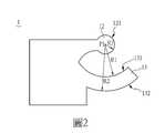
請參照圖2及圖3。圖2係根據本發明之一實施例所繪示之第一卡合件1的示意圖,以及圖3係根據本發明之一實施例所繪示之第二卡合件3的示意圖,如圖2所繪示,第一凸部13具有內側邊131以及外側邊132,內側邊131以及外側邊132皆呈圓弧形。於此實施例中,利用圓心P1以及半徑R1形成第一凸部13的內側邊131,利用圓心P1以及半徑R2形成第一凸部13的外側邊132,以及利用圓心P1以及半徑R3形成頭部12的環形側邊121。值得注意的是,內側邊131具有第一曲率,外側邊132具有第二曲率,環形側邊121具有第三曲率,第一曲率大於第二曲率,並且第三曲率大於第一曲率。Please refer to Figure 2 and Figure 3. FIG. 2 is a schematic diagram of the first engaging
承上述,如圖3所繪示,第二凸部32具有內側邊321以及外側邊322,內側邊321以及外側邊322皆呈圓弧形。於此實施例中,利用圓心P1以及半徑R3形成第二凸部32的內側邊321,利用圓心P1以及半徑R1形成第二凸部32的外側邊322。類似地,第三凸部33具有內側邊331,內側邊331係呈圓弧形。再者,利用圓心P1以及半徑R2形成第三凸部33的內側邊331。值得注意的是,內側邊321具有第三曲率,外側邊322具有第一曲率,內側邊331具有第二曲率,第一曲率大於第二曲率,並且第三曲率大於第一曲率。In view of the above, as shown in FIG. 3, the second
請參閱圖4。圖4係根據本案之一些實施例所繪示之一種接頭組裝方法400的流程圖。在本實施例中,圖4所示之接頭組裝方法可以應用於圖1的接頭結構100上,接頭結構100所包含的第一卡合件1以及第二卡合件3分別裝設於不同實體的外表面,不同實體可以藉由第一卡合件1以及第二卡合件3彼此連接。Please refer to Figure 4. FIG. 4 is a flowchart of a
接著,接頭組裝方法400首先執行步驟S410計算第一卡合件的第一裝設位置以及第二卡合件的第二裝設位置,以及步驟S420裝設第一卡合件於第一裝設位置以及第二卡合件於第二裝設位置。於本實施例中,請參閱圖5,圖5係根據本發明之一實施例所繪示之接頭結構裝設於實體表面的示意圖。第一裝設位置係位於第一實體5的表面,第二裝設位置係位於第二實體7的表面。如圖5所示,第一裝設位置高於第一實體5的重心G1,同樣地,第二裝設位置也須高於第二實體7的重心G2。值得注意的是,第二裝設位置需要與第一裝設位置對應以便於兩者卡合。Next, the
接著,接頭組裝方法400執行步驟S430根據第一實體的重心位置計算吊掛位置以及計算第一實體表面的中心位置,當第一實體於吊掛狀態時,吊掛位置與重心位置的連線方向與中心位置與重心位置的連線方向形成第一夾角。於本實施例中,請參閱圖6,圖6係根據本發明之一實施例所繪示之吊掛機與吊掛位置的示意圖。如圖6所示,根據第一實體5的側表面所對應的距離d1計算中心位置CP,吊掛位置RP係位於第一實體5的側表面,吊掛位置RP與第一實體5的上表面具有距離d2,中心位置CP與第一實體5的上表面具有距離d3。值得注意的是,距離d2大於距離d3,換言之,吊掛位置RP的水平位置低於中心位置CP的水平位置。Next, the
承上述,請參閱圖7。圖7係根據本發明之一實施例所繪示之第一實體於吊掛狀態的示意圖。如圖7所示,當吊掛機將第一實體5吊起時,吊掛位置RP與重心G1位置的連線方向與中心位置CP與重心G1位置的連線方向形成第一夾角θ 1。於此實施例中,第一夾角θ 1係由於第一實體5被吊起時,因吊掛位置RP與重力作用形成的傾角。因此,吊掛位置需與第一實體5的形狀及重量配合以形成適當的傾角,以利後續第一卡合件和第二卡合件的接合。For the above, please refer to Figure 7. FIG. 7 is a schematic diagram of the first entity in a hanging state according to an embodiment of the present invention. As shown in Fig. 7, when the crane hoists the
承上述,接頭組裝方法400執行步驟S440組合第一卡合件與第二卡合件,當第一卡合件與第二卡合件於組配狀態時,第一實體以頭部為旋轉中心旋轉由第二夾角所形成的角度以帶動第一卡合件與第二卡合件卡合。於本實施例中,請參閱圖8,圖8係根據本發明之一實施例所繪示之第一卡合件與第二卡合件於組配狀態的示意圖。如圖8所示,藉由重力將第一卡合件1的頭部12抵靠於第二卡合件3,使得第一卡合件1與第二卡合件3於組配狀態。In view of the above, the
承上述,請參閱圖9,圖9係根據本發明之一實施例所繪示之第一實體及第二實體透過接頭結構連接的示意圖。如圖9所示,當第一卡合件1的頭部12抵靠於第二卡合件3後,吊掛機移動距離d4使得第一實體1帶動第一卡合件1旋轉第二夾角θ 2所形成的角度,進一步讓第一卡合件1與第二卡合件3卡合。值得注意的是,第二夾角θ 2為第一夾角θ 1的餘角,並且第一凸部13的內側邊131對應的度數與第二夾角θ 2的角度相同。In view of the above, please refer to FIG. 9. FIG. 9 is a schematic diagram of a first entity and a second entity connected through a joint structure according to an embodiment of the present invention. As shown in FIG. 9, when the
承上述,第一卡合件1與第二卡合件3於組配狀態時,第一實體1以頭部12為旋轉中心旋轉由第二夾角θ 2所形成的角度,使得第一凸部13的外周緣接觸到第二凸部32的外周緣,並滑動卡合於第二凸部32以及第三凸部33形成的凹部之間。值得注意的是,由於第一實體1帶動第一卡合件1旋轉的角度(第二夾角θ 2)與第一凸部13的內側邊131對應的度數相同,因此第一凸部13可以滑動卡合於凹部。In view of the above, when the first engaging
承上述,於此實施例中,係由第一卡合件1的頭部12抵靠於第二卡合件3,並且以頭部12為旋轉中心旋轉卡合於第二凸部32以及第三凸部33之間。如此一來,吊車可以利用接頭結構直接組裝被吊物(例如,鋼筋、水泥塊),於組裝時不需要額外人力協助校準,也不需要搭配額外的機具,因此可以提升組裝的速度也降低導入現有施工環境的門檻。In accordance with the above, in this embodiment, the
於另一實施例中,也可以係由第二卡合件3抵靠於頭部12的環形側邊121,並且以頭部12為旋轉中心旋轉卡合於頭部12以及第一凸部13之間。值得注意的是,當第一卡合件1與第二卡合件3卡合後,可以再利用其它螺栓結構強化第一卡合件1與第二卡合件3之間的連接,本揭示不限於此。In another embodiment, the second engaging
綜上所述,本發明之接頭結構以及接頭組裝方法,其主要係提出可以利用被吊物的重量以及其自身的旋轉,配合接頭結構達到自動化組裝的效果。因此,吊車可以利用接頭結構直接組裝被吊物,在組裝時不需要額外人力協助校準,也不需要搭配額外的機具,達到降低人力成本以及提升組裝的速度的功效。In summary, the joint structure and joint assembly method of the present invention mainly propose that the weight of the suspended object and its own rotation can be used to cooperate with the joint structure to achieve the effect of automatic assembly. Therefore, the crane can directly assemble the suspended object by using the joint structure, and does not require additional manpower to assist in calibration during assembly, and does not need to be equipped with additional tools, thereby achieving the effects of reducing labor costs and increasing assembly speed.
上述的實施例僅用來例舉本發明的實施態樣,以及闡釋本發明的技術特徵,並非用來限制本發明的保護範疇。任何熟悉此技術者可輕易完成的改變或均等性的安排均屬於本發明所主張的範圍,本發明的權利保護範圍應以申請專利範圍為準。The above-mentioned embodiments are only used to illustrate the implementation of the present invention and explain the technical features of the present invention, and are not used to limit the protection scope of the present invention. Any changes or equivalence arrangements that can be easily completed by those familiar with this technology belong to the scope of the present invention, and the scope of protection of the rights of the present invention shall be subject to the scope of the patent application.
100:接頭結構100: Joint structure
1:第一卡合件1: The first card
11:第一主體11: The first subject
12:頭部12: head
13:第一凸部13: The first convex part
3:第二卡合件3: The second engaging piece
31:第二主體31: The second subject
32:第二凸部32: second convex
33:第三凸部33: Third convex part
D1、D2:方向D1, D2: direction
Claims (15)
Translated fromChinesePriority Applications (3)
| Application Number | Priority Date | Filing Date | Title |
|---|---|---|---|
| TW109138330ATWI739649B (en) | 2020-11-03 | 2020-11-03 | Joint structure and method for assembling a joint structure |
| US17/167,339US11635100B2 (en) | 2020-11-03 | 2021-02-04 | Joint structure and method for assembling a joint structure |
| US18/162,913US20230175540A1 (en) | 2020-11-03 | 2023-02-01 | Joint structure and method for assembling a joint structure |
Applications Claiming Priority (1)
| Application Number | Priority Date | Filing Date | Title |
|---|---|---|---|
| TW109138330ATWI739649B (en) | 2020-11-03 | 2020-11-03 | Joint structure and method for assembling a joint structure |
Publications (2)
| Publication Number | Publication Date |
|---|---|
| TWI739649Btrue TWI739649B (en) | 2021-09-11 |
| TW202218972A TW202218972A (en) | 2022-05-16 |
Family
ID=78778160
Family Applications (1)
| Application Number | Title | Priority Date | Filing Date |
|---|---|---|---|
| TW109138330ATWI739649B (en) | 2020-11-03 | 2020-11-03 | Joint structure and method for assembling a joint structure |
Country Status (2)
| Country | Link |
|---|---|
| US (2) | US11635100B2 (en) |
| TW (1) | TWI739649B (en) |
Citations (2)
| Publication number | Priority date | Publication date | Assignee | Title |
|---|---|---|---|---|
| US20020152593A1 (en)* | 2001-04-20 | 2002-10-24 | Steven Hong | Coupling self-locking hook |
| CN111655563A (en)* | 2018-01-30 | 2020-09-11 | 福伊特专利有限公司 | Adapter part for adapting to a coupler head, coupler head with an adapter part and method for adapting a coupler head |
Family Cites Families (4)
| Publication number | Priority date | Publication date | Assignee | Title |
|---|---|---|---|---|
| GB2225404A (en)* | 1988-11-07 | 1990-05-30 | Burness Corlett & Partners | Joints between the edges of panels |
| BE1010487A6 (en)* | 1996-06-11 | 1998-10-06 | Unilin Beheer Bv | FLOOR COATING CONSISTING OF HARD FLOOR PANELS AND METHOD FOR MANUFACTURING SUCH FLOOR PANELS. |
| EP3718437A1 (en)* | 2019-04-05 | 2020-10-07 | Välinge Innovation AB | Method for assembling a piece of furniture |
| US11541553B2 (en)* | 2019-05-31 | 2023-01-03 | House of Design LLC | Systems and methods for pre-plating structural members |
- 2020
- 2020-11-03TWTW109138330Apatent/TWI739649B/enactive
- 2021
- 2021-02-04USUS17/167,339patent/US11635100B2/enactiveActive
- 2023
- 2023-02-01USUS18/162,913patent/US20230175540A1/ennot_activeAbandoned
Patent Citations (2)
| Publication number | Priority date | Publication date | Assignee | Title |
|---|---|---|---|---|
| US20020152593A1 (en)* | 2001-04-20 | 2002-10-24 | Steven Hong | Coupling self-locking hook |
| CN111655563A (en)* | 2018-01-30 | 2020-09-11 | 福伊特专利有限公司 | Adapter part for adapting to a coupler head, coupler head with an adapter part and method for adapting a coupler head |
Also Published As
| Publication number | Publication date |
|---|---|
| US20220136538A1 (en) | 2022-05-05 |
| US11635100B2 (en) | 2023-04-25 |
| TW202218972A (en) | 2022-05-16 |
| US20230175540A1 (en) | 2023-06-08 |
Similar Documents
| Publication | Publication Date | Title |
|---|---|---|
| TWI739649B (en) | Joint structure and method for assembling a joint structure | |
| CN106049198A (en) | Stepless height adjustment type built-in vibration isolation device | |
| JP2023165995A5 (en) | Renovated sash, sash and sash renovation method | |
| CN115098956A (en) | A design method of curved bulkhead and curved bulkhead | |
| CN205876927U (en) | Automatic positioning bolt and robot in deciding | |
| CN111424999A (en) | Novel masonry wall pointing tool | |
| CN211314446U (en) | A wind turbine and its hub | |
| CN206913180U (en) | A kind of arm and articulated robot for articulated robot | |
| CN211572151U (en) | Aluminum plate multi-angle rotating assembly | |
| CN216276592U (en) | Light concrete internal and external corner structure in prefabricated building | |
| CN212352377U (en) | A kind of self-locking device of mould box arm for producing aerated concrete blocks | |
| CN211201216U (en) | Horizontal stop device of rack integral hoisting | |
| CN112064597A (en) | The method of arranging the rear end plate of the trigeminal inclined arm in the vertical plane of the projection line of the middle arm | |
| CN219710690U (en) | Mounting structure of aluminum plate with adjustable angle | |
| CN222493804U (en) | Compatible sand-blasting and paint-spraying protection device | |
| CN208533897U (en) | A new type of stair guard | |
| CN210571996U (en) | Building engineering detects with detecting mirror | |
| CN218290146U (en) | A steel truss lifting tool | |
| CN218001806U (en) | Hoist and mount formula ventilation blower | |
| CN217775780U (en) | A limit block that can adjust multiple angles | |
| CN204919914U (en) | Fixture device | |
| CN205008646U (en) | Installation face carries out cast iron gasket adjusted convenient to to mechanical cutter head | |
| CN209309114U (en) | engine crankshaft assembly | |
| CN223278380U (en) | Anti-dislocation device for accessory | |
| JPH057229Y2 (en) |