TWI738897B - Electrical connector - Google Patents
Electrical connectorDownload PDFInfo
- Publication number
- TWI738897B TWI738897BTW106136336ATW106136336ATWI738897BTW I738897 BTWI738897 BTW I738897BTW 106136336 ATW106136336 ATW 106136336ATW 106136336 ATW106136336 ATW 106136336ATW I738897 BTWI738897 BTW I738897B
- Authority
- TW
- Taiwan
- Prior art keywords
- electrical connector
- side wall
- terminal
- housing
- base
- Prior art date
Links
- 230000013011matingEffects0.000claimsabstractdescription11
- 239000002184metalSubstances0.000claimsabstractdescription8
- 238000007789sealingMethods0.000claimsabstractdescription7
- 239000004831Hot glueSubstances0.000claimsdescription13
- 238000003466weldingMethods0.000claimsdescription3
- 238000005452bendingMethods0.000abstractdescription3
- 239000012212insulatorSubstances0.000description8
- 238000003032molecular dockingMethods0.000description4
- 239000011248coating agentSubstances0.000description1
- 238000000576coating methodMethods0.000description1
- 238000001816coolingMethods0.000description1
- 238000012986modificationMethods0.000description1
- 230000004048modificationEffects0.000description1
- NJPPVKZQTLUDBO-UHFFFAOYSA-NnovaluronChemical compoundC1=C(Cl)C(OC(F)(F)C(OC(F)(F)F)F)=CC=C1NC(=O)NC(=O)C1=C(F)C=CC=C1FNJPPVKZQTLUDBO-UHFFFAOYSA-N0.000description1
- 238000005476solderingMethods0.000description1
- XLYOFNOQVPJJNP-UHFFFAOYSA-NwaterSubstancesOXLYOFNOQVPJJNP-UHFFFAOYSA-N0.000description1
- 238000004078waterproofingMethods0.000description1
Images


Classifications
- H—ELECTRICITY
- H01—ELECTRIC ELEMENTS
- H01R—ELECTRICALLY-CONDUCTIVE CONNECTIONS; STRUCTURAL ASSOCIATIONS OF A PLURALITY OF MUTUALLY-INSULATED ELECTRICAL CONNECTING ELEMENTS; COUPLING DEVICES; CURRENT COLLECTORS
- H01R13/00—Details of coupling devices of the kinds covered by groups H01R12/70 or H01R24/00 - H01R33/00
- H01R13/648—Protective earth or shield arrangements on coupling devices, e.g. anti-static shielding
- H01R13/658—High frequency shielding arrangements, e.g. against EMI [Electro-Magnetic Interference] or EMP [Electro-Magnetic Pulse]
- H01R13/6581—Shield structure
- H—ELECTRICITY
- H01—ELECTRIC ELEMENTS
- H01R—ELECTRICALLY-CONDUCTIVE CONNECTIONS; STRUCTURAL ASSOCIATIONS OF A PLURALITY OF MUTUALLY-INSULATED ELECTRICAL CONNECTING ELEMENTS; COUPLING DEVICES; CURRENT COLLECTORS
- H01R13/00—Details of coupling devices of the kinds covered by groups H01R12/70 or H01R24/00 - H01R33/00
- H01R13/648—Protective earth or shield arrangements on coupling devices, e.g. anti-static shielding
- H01R13/658—High frequency shielding arrangements, e.g. against EMI [Electro-Magnetic Interference] or EMP [Electro-Magnetic Pulse]
- H01R13/6591—Specific features or arrangements of connection of shield to conductive members
- H01R13/6594—Specific features or arrangements of connection of shield to conductive members the shield being mounted on a PCB and connected to conductive members
- H01R13/6595—Specific features or arrangements of connection of shield to conductive members the shield being mounted on a PCB and connected to conductive members with separate members fixing the shield to the PCB
- H—ELECTRICITY
- H01—ELECTRIC ELEMENTS
- H01R—ELECTRICALLY-CONDUCTIVE CONNECTIONS; STRUCTURAL ASSOCIATIONS OF A PLURALITY OF MUTUALLY-INSULATED ELECTRICAL CONNECTING ELEMENTS; COUPLING DEVICES; CURRENT COLLECTORS
- H01R13/00—Details of coupling devices of the kinds covered by groups H01R12/70 or H01R24/00 - H01R33/00
- H01R13/46—Bases; Cases
- H01R13/502—Bases; Cases composed of different pieces
- H—ELECTRICITY
- H01—ELECTRIC ELEMENTS
- H01R—ELECTRICALLY-CONDUCTIVE CONNECTIONS; STRUCTURAL ASSOCIATIONS OF A PLURALITY OF MUTUALLY-INSULATED ELECTRICAL CONNECTING ELEMENTS; COUPLING DEVICES; CURRENT COLLECTORS
- H01R13/00—Details of coupling devices of the kinds covered by groups H01R12/70 or H01R24/00 - H01R33/00
- H01R13/46—Bases; Cases
- H01R13/52—Dustproof, splashproof, drip-proof, waterproof, or flameproof cases
- H01R13/5202—Sealing means between parts of housing or between housing part and a wall, e.g. sealing rings
- H—ELECTRICITY
- H01—ELECTRIC ELEMENTS
- H01R—ELECTRICALLY-CONDUCTIVE CONNECTIONS; STRUCTURAL ASSOCIATIONS OF A PLURALITY OF MUTUALLY-INSULATED ELECTRICAL CONNECTING ELEMENTS; COUPLING DEVICES; CURRENT COLLECTORS
- H01R13/00—Details of coupling devices of the kinds covered by groups H01R12/70 or H01R24/00 - H01R33/00
- H01R13/46—Bases; Cases
- H01R13/52—Dustproof, splashproof, drip-proof, waterproof, or flameproof cases
- H01R13/5216—Dustproof, splashproof, drip-proof, waterproof, or flameproof cases characterised by the sealing material, e.g. gels or resins
- H—ELECTRICITY
- H01—ELECTRIC ELEMENTS
- H01R—ELECTRICALLY-CONDUCTIVE CONNECTIONS; STRUCTURAL ASSOCIATIONS OF A PLURALITY OF MUTUALLY-INSULATED ELECTRICAL CONNECTING ELEMENTS; COUPLING DEVICES; CURRENT COLLECTORS
- H01R12/00—Structural associations of a plurality of mutually-insulated electrical connecting elements, specially adapted for printed circuits, e.g. printed circuit boards [PCB], flat or ribbon cables, or like generally planar structures, e.g. terminal strips, terminal blocks; Coupling devices specially adapted for printed circuits, flat or ribbon cables, or like generally planar structures; Terminals specially adapted for contact with, or insertion into, printed circuits, flat or ribbon cables, or like generally planar structures
- H01R12/70—Coupling devices
- H01R12/71—Coupling devices for rigid printing circuits or like structures
- H01R12/72—Coupling devices for rigid printing circuits or like structures coupling with the edge of the rigid printed circuits or like structures
- H01R12/722—Coupling devices for rigid printing circuits or like structures coupling with the edge of the rigid printed circuits or like structures coupling devices mounted on the edge of the printed circuits
- H01R12/725—Coupling devices for rigid printing circuits or like structures coupling with the edge of the rigid printed circuits or like structures coupling devices mounted on the edge of the printed circuits containing contact members presenting a contact carrying strip, e.g. edge-like strip
- H—ELECTRICITY
- H01—ELECTRIC ELEMENTS
- H01R—ELECTRICALLY-CONDUCTIVE CONNECTIONS; STRUCTURAL ASSOCIATIONS OF A PLURALITY OF MUTUALLY-INSULATED ELECTRICAL CONNECTING ELEMENTS; COUPLING DEVICES; CURRENT COLLECTORS
- H01R13/00—Details of coupling devices of the kinds covered by groups H01R12/70 or H01R24/00 - H01R33/00
- H01R13/648—Protective earth or shield arrangements on coupling devices, e.g. anti-static shielding
- H01R13/658—High frequency shielding arrangements, e.g. against EMI [Electro-Magnetic Interference] or EMP [Electro-Magnetic Pulse]
- H01R13/6581—Shield structure
- H01R13/6585—Shielding material individually surrounding or interposed between mutually spaced contacts
- H—ELECTRICITY
- H01—ELECTRIC ELEMENTS
- H01R—ELECTRICALLY-CONDUCTIVE CONNECTIONS; STRUCTURAL ASSOCIATIONS OF A PLURALITY OF MUTUALLY-INSULATED ELECTRICAL CONNECTING ELEMENTS; COUPLING DEVICES; CURRENT COLLECTORS
- H01R13/00—Details of coupling devices of the kinds covered by groups H01R12/70 or H01R24/00 - H01R33/00
- H01R13/648—Protective earth or shield arrangements on coupling devices, e.g. anti-static shielding
- H01R13/658—High frequency shielding arrangements, e.g. against EMI [Electro-Magnetic Interference] or EMP [Electro-Magnetic Pulse]
- H01R13/6591—Specific features or arrangements of connection of shield to conductive members
- H01R13/6594—Specific features or arrangements of connection of shield to conductive members the shield being mounted on a PCB and connected to conductive members
- H—ELECTRICITY
- H01—ELECTRIC ELEMENTS
- H01R—ELECTRICALLY-CONDUCTIVE CONNECTIONS; STRUCTURAL ASSOCIATIONS OF A PLURALITY OF MUTUALLY-INSULATED ELECTRICAL CONNECTING ELEMENTS; COUPLING DEVICES; CURRENT COLLECTORS
- H01R24/00—Two-part coupling devices, or either of their cooperating parts, characterised by their overall structure
- H01R24/60—Contacts spaced along planar side wall transverse to longitudinal axis of engagement
Landscapes
- Chemical & Material Sciences (AREA)
- Dispersion Chemistry (AREA)
- Connector Housings Or Holding Contact Members (AREA)
- Details Of Connecting Devices For Male And Female Coupling (AREA)
Abstract
Description
Translated fromChinese本發明係有關一種電連接器。The invention relates to an electrical connector.
中華民國發明專利公告第TWI552455B號揭示了一種防水連接器,其包括複數接觸件、金屬罩殼、絕緣殼體及無接縫的防水構件。所述防水構件嵌入於絕緣殼體外周的環狀溝槽。所述金屬罩殼包括第一側壁、第二側壁及連接所述第一側壁與所述第二側壁的兩端壁。所述金屬罩殼由金屬板彎折形成而在其第二側壁處具有結合縫,水會從結合縫處滲入連接器內部,從而影響連接器的工作能力。The Republic of China Invention Patent Publication No. TWI552455B discloses a waterproof connector, which includes a plurality of contacts, a metal casing, an insulating shell, and a seamless waterproof member. The waterproof member is embedded in the annular groove on the outer periphery of the insulating housing. The metal casing includes a first side wall, a second side wall, and two end walls connecting the first side wall and the second side wall. The metal casing is formed by bending a metal plate to have a joint seam at the second side wall thereof, and water will penetrate into the connector from the joint seam, thereby affecting the working ability of the connector.
因此,確有必要提供一種新的電連接器。Therefore, it is indeed necessary to provide a new electrical connector.
本發明的目的在於:提供一種具有防水功能的電連接器。The purpose of the present invention is to provide an electrical connector with waterproof function.
為實現上述目的,本發明可採用如下技術方案來實現:一種電連接器,其包括端子座及第一殼體,所述端子座包括基座、自所述基座延伸的對接舌板及端子,所述第一殼體包括相對的第一側壁、第二側壁及連接所述第一、第二側壁的兩端壁,所述第一殼體包圍所述對接舌板而在兩者之間形成對接腔,所述第一殼體由金屬板彎折形成而在其第二側壁處具有結合縫,所述電連接器還包括密封層,所述密封層粘附在所述第二側壁而將所述結合縫密封。In order to achieve the above objectives, the present invention can be achieved by adopting the following technical solutions:An electrical connector includes a terminal base and a first housing. The terminal base includes a base, a mating tongue extending from the base and a terminal. The first housing includes opposing first side walls and a first housing. Two side walls and two end walls connecting the first and second side walls, the first housing surrounds the butting tongue plate to form a butting cavity between the two, and the first housing is bent by a metal plate The electrical connector is formed to have a joint seam at its second side wall, and the electrical connector further includes a sealing layer that is adhered to the second side wall to seal the joint seam.
與習知技術相比,本發明電連接器還包括密封層,所述密封層將第一殼體的結合縫密封,從而實現電連接器的防水功能。Compared with the prior art, the electrical connector of the present invention further includes a sealing layer that seals the joint seam of the first housing, thereby realizing the waterproof function of the electrical connector.
100:電連接器100: electrical connector
11:基座11: Pedestal
13:對接腔13: Docking cavity
141:第一絕緣體141: first insulator
143:第一基部143: first base
15:第二端子模組15: The second terminal module
152:第二舌板152: second tongue
154:第二導電端子154: second conductive terminal
161:鎖扣側緣161: Lock side edge
20:第一殼體20: The first shell
211:肋條211: Rib
221:扣持孔221: Buckle hole
223:凹孔223: Hole
225:結合縫225: joint seam
30:第二殼體30: second shell
32:豎直部32: vertical part
34:貫穿孔34: Through hole
41:通孔41: Through hole
10:端子座10: Terminal block
12:對接舌板12: Butt tongue
14:第一端子模組14: The first terminal module
142:第一舌板142: First tongue
144:第一導電端子144: The first conductive terminal
151:第二絕緣體151: second insulator
153:第二基部153: second base
16:遮蔽板16: shielding board
17:外包覆部17: Outer coating
21:第一側壁21: The first side wall
22:第二側壁22: second side wall
222:彈性臂222: Flexible arm
224:凸出部224: protruding part
23:端壁23: end wall
31:水平部31: Horizontal part
33:焊接腳33: Welding feet
40:熱熔膠40: hot melt adhesive
50:塑膠塊50: plastic block
第一圖係本發明電連接器的立體圖。The first figure is a perspective view of the electrical connector of the present invention.
第二圖係第一圖所示電連接器的立體分解圖。The second figure is a three-dimensional exploded view of the electrical connector shown in the first figure.
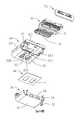
第三圖係第二圖所示電連接器進一步的立體分解圖。The third figure is a further perspective exploded view of the electrical connector shown in the second figure.
第四圖係第三圖所示電連接器進一步的立體分解圖。The fourth figure is a further three-dimensional exploded view of the electrical connector shown in the third figure.
第五圖係第四圖所示端子座的立體分解圖。Figure 5 is an exploded perspective view of the terminal block shown in Figure 4.
第六圖係第一圖所示電連接器沿Ⅵ-Ⅵ方向的剖視圖。Figure 6 is a cross-sectional view of the electrical connector shown in Figure 1 along the VI-VI direction.
參閱第一圖至第四圖,本發明公開了一種電連接器100,其可安裝於電路板(未圖示)。所述電連接器100包括端子座10、第一殼體20及第二殼體30。所述端子座10包括基座11及自所述基座11延伸的對接舌板12。所述第一殼體20包圍所述對接舌板12而在兩者之間形成對接腔13。所述第二殼體30安裝於所述第一殼體20的外側。所述第二殼體30上設有貫穿孔34,藉由所述貫穿孔34向所述電連接器100內注入塑膠,待冷卻後形成塑膠塊50用以防水。Referring to the first to fourth figures, the present invention discloses an
參閱第五圖至第六圖,所述端子座10包括第一端子模組14、第二端子模組15及設置在所述第一端子模組14與所述第二端子模組15之間的遮蔽板16,所述遮蔽板16具有鎖扣側緣161。所述第一端子模組14包括第一絕緣體141及埋設於所述第一絕緣體141的複數第一導電端子144。所述第一絕緣體141包括第一舌板142及自所述第一舌板142延伸的第一基部143。所述第二端子模組15包括第二絕緣體151及埋設於所述第二絕緣體151的複數第二導電端子154。所述第二絕緣體151包括第二舌板152及自所述第二舌板152延伸的第二基部153。所述第一、第二端子模組14,15及遮蔽板16組裝在一起後再在第一、第二舌板142,152及第一、第二基部143,153的部分外側注塑成型有外包覆部17而構成完整的上述對接舌板12。Referring to the fifth to sixth figures, the
所述第一殼體20包括相對的第一側壁21、第二側壁22及連接所述第一、第二側壁21,22的兩端壁23。所述第一殼體20由金屬板彎折形成而在其第二側壁22處具有結合縫225。所述電連接器100還包括熱熔膠40。所述熱熔膠40粘附在所述第二側壁22而將所述結合縫225密封,所述熱熔膠40覆蓋整個所述第二側壁22,從而形成密封層。所述第二側壁22設有扣持孔221,所述扣持孔221的內緣向所述對接腔13內延伸有彈性臂222,所述熱熔膠40設有與所述扣持孔221對齊的通孔41。所述第二側壁22設有凹孔223,所述凹孔223內具有向內固定在所述基座11的凸出部224,所述熱熔膠40覆蓋所述凹孔223。所述第一側壁21具有向所述對接腔13內凸伸的肋條211,所述肋條211係所述第一側壁21向內衝壓而形成且與所述第一側壁21之間無任何縫隙,所述肋條211沿前後方向延伸。The
所述第二殼體30藉由所述熱熔膠40粘附在所述第二側壁22。所述第二殼體30包括水平部31及自所述水平部31兩側向上彎折的豎直部32,所述水平部31藉由所述熱熔膠40粘附在所述第二側壁22並覆蓋所述扣持孔221及所述凹孔223,所述豎直部32彎折出電路板焊接腳33。The
綜上所述,本發明確已符合發明專利之要件,爰依法提出專利申請。惟,以上所述僅為本發明之較佳實施方式,自不能以此限定本發明之權利範圍。舉凡所屬技術領域中具有通常知識者爰依本發明之精神所作之等效修飾或變化,皆仍涵蓋於後附之申請專利範圍內。In summary, this publication clearly meets the requirements of an invention patent, and Yan filed a patent application in accordance with the law. However, the above descriptions are only the preferred embodiments of the present invention, and the scope of rights of the present invention cannot be limited by this. All equivalent modifications or changes made by those with ordinary knowledge in the technical field based on the spirit of the present invention are still covered in the scope of the appended patent application.
12:對接舌板12: Butt tongue
20:第一殼體20: The first shell
211:肋條211: Rib
221:扣持孔221: Buckle hole
223:凹孔223: Hole
13:對接腔13: Docking cavity
21:第一側壁21: The first side wall
22:第二側壁22: second side wall
222:彈性臂222: Flexible arm
224:凸出部224: protruding part
225:結合縫225: joint seam
30:第二殼體30: second shell
32:豎直部32: vertical part
40:熱熔膠40: hot melt adhesive
23:端壁23: end wall
31:水平部31: Horizontal part
33:焊接腳33: Welding feet
41:通孔41: Through hole
Claims (8)
Translated fromChineseApplications Claiming Priority (3)
| Application Number | Priority Date | Filing Date | Title |
|---|---|---|---|
| CN201611176661.5ACN108206360B (en) | 2016-12-19 | 2016-12-19 | Electrical connector |
| CN201611176661.5 | 2016-12-19 | ||
| ??201611176661.5 | 2016-12-19 |
Publications (2)
| Publication Number | Publication Date |
|---|---|
| TW201834329A TW201834329A (en) | 2018-09-16 |
| TWI738897Btrue TWI738897B (en) | 2021-09-11 |
Family
ID=62556376
Family Applications (1)
| Application Number | Title | Priority Date | Filing Date |
|---|---|---|---|
| TW106136336ATWI738897B (en) | 2016-12-19 | 2017-10-23 | Electrical connector |
Country Status (3)
| Country | Link |
|---|---|
| US (1) | US10044148B2 (en) |
| CN (1) | CN108206360B (en) |
| TW (1) | TWI738897B (en) |
Families Citing this family (9)
| Publication number | Priority date | Publication date | Assignee | Title |
|---|---|---|---|---|
| CN107046206B (en)* | 2017-01-23 | 2021-07-20 | 富士康(昆山)电脑接插件有限公司 | Electrical connector |
| CN109149215B (en)* | 2017-06-19 | 2021-08-20 | 富士康(昆山)电脑接插件有限公司 | Electrical connector |
| CN109411956B (en)* | 2017-08-18 | 2021-07-20 | 富士康(昆山)电脑接插件有限公司 | Electrical connector |
| CN207320487U (en)* | 2017-08-18 | 2018-05-04 | 富士康(昆山)电脑接插件有限公司 | Electric connector |
| CN109428190B (en)* | 2017-08-25 | 2021-10-26 | 富士康(昆山)电脑接插件有限公司 | Electric connector combination and manufacturing method thereof |
| CN209374726U (en)* | 2018-11-09 | 2019-09-10 | 富鼎精密工业(郑州)有限公司 | Electric connector |
| US11764534B2 (en) | 2021-05-05 | 2023-09-19 | Amphenol East Asia Electronic Technology (Shenzhen) Co., Ltd. | Type C female side connector |
| US11621513B2 (en) | 2021-06-02 | 2023-04-04 | Amphenol East Asia Electronic Technology (Shenzhen) Co., Ltd. | Vehicle USB Type-C connector |
| CN113540874B (en)* | 2021-07-08 | 2025-05-27 | 深圳市精睿兴业科技有限公司 | Electrical connector and electronic equipment |
Citations (2)
| Publication number | Priority date | Publication date | Assignee | Title |
|---|---|---|---|---|
| TWM524576U (en)* | 2015-12-28 | 2016-06-21 | 鴻騰精密科技股份有限公司 | Electrical connector |
| US20160181722A1 (en)* | 2014-12-19 | 2016-06-23 | Advanced-Connectek Inc. | Waterproof electrical receptacle connector |
Family Cites Families (13)
| Publication number | Priority date | Publication date | Assignee | Title |
|---|---|---|---|---|
| CN100560340C (en)* | 2005-03-30 | 2009-11-18 | 联想(北京)有限公司 | Bonding method and device for metal and plastic composite face shell |
| US8388380B1 (en)* | 2011-10-20 | 2013-03-05 | Hon Hai Precision Ind. Co., Ltd | Waterproof connector with board-mounted soldering plate for improved sealing |
| CN202772336U (en)* | 2012-09-18 | 2013-03-06 | 上海莫仕连接器有限公司 | Electric connector |
| CN203434357U (en)* | 2013-07-15 | 2014-02-12 | 番禺得意精密电子工业有限公司 | Electric connector |
| CN203800282U (en)* | 2013-11-29 | 2014-08-27 | 富士康(昆山)电脑接插件有限公司 | Electric connector |
| JP5925865B1 (en) | 2014-11-14 | 2016-05-25 | 日本航空電子工業株式会社 | Waterproof connector |
| CN105449434A (en)* | 2015-11-24 | 2016-03-30 | 连展科技(深圳)有限公司 | Electric connector |
| CN105390839B (en)* | 2015-11-27 | 2018-08-31 | 富士康(昆山)电脑接插件有限公司 | Electric connector and its manufacturing method |
| CN205376880U (en)* | 2015-12-03 | 2016-07-06 | 连展科技(深圳)有限公司 | Electric connector |
| CN105514669B (en)* | 2015-12-14 | 2019-08-30 | 富士康(昆山)电脑接插件有限公司 | Electric connector and its manufacturing method |
| CN105514703B (en)* | 2015-12-31 | 2019-06-28 | 富士康(昆山)电脑接插件有限公司 | Electric connector and combinations thereof |
| US9887485B2 (en)* | 2016-03-07 | 2018-02-06 | Amphenol Corporation | Ruggedized electrical connector |
| US9899779B1 (en)* | 2017-01-18 | 2018-02-20 | Assem Technology Co., Ltd. | Waterproof electric connector module |
- 2016
- 2016-12-19CNCN201611176661.5Apatent/CN108206360B/enactiveActive
- 2017
- 2017-10-23TWTW106136336Apatent/TWI738897B/enactive
- 2017-12-18USUS15/844,656patent/US10044148B2/enactiveActive
Patent Citations (2)
| Publication number | Priority date | Publication date | Assignee | Title |
|---|---|---|---|---|
| US20160181722A1 (en)* | 2014-12-19 | 2016-06-23 | Advanced-Connectek Inc. | Waterproof electrical receptacle connector |
| TWM524576U (en)* | 2015-12-28 | 2016-06-21 | 鴻騰精密科技股份有限公司 | Electrical connector |
Also Published As
| Publication number | Publication date |
|---|---|
| US10044148B2 (en) | 2018-08-07 |
| CN108206360B (en) | 2021-08-20 |
| CN108206360A (en) | 2018-06-26 |
| US20180175556A1 (en) | 2018-06-21 |
| TW201834329A (en) | 2018-09-16 |
Similar Documents
| Publication | Publication Date | Title |
|---|---|---|
| TWI738897B (en) | Electrical connector | |
| CN204289872U (en) | Electric connector | |
| US10312628B2 (en) | Electrical connector with forward and rearward waterproof sealing | |
| TWI506879B (en) | Electrical connector | |
| CN104838545B (en) | waterproof connector | |
| US9397438B2 (en) | Electrical connector having an over-molded sealing member | |
| TWI772429B (en) | Electrical connector | |
| CN102403618B (en) | The manufacture method of water-proof connector | |
| TWI605642B (en) | Connector producing method and connector | |
| TWM527172U (en) | Waterproof socket electric coupler | |
| KR102510778B1 (en) | Connector for waterproof | |
| TWM551361U (en) | Electrical connector | |
| TW201626652A (en) | Waterproof connector | |
| JP2017027671A (en) | Water proof connector and connector assembly | |
| TWM561345U (en) | Receptacle electrical connector | |
| TWM454005U (en) | Electrical connector | |
| US20160056528A1 (en) | Mobile device | |
| JP4873358B2 (en) | Waterproof mounting structure for board connector | |
| TWM541133U (en) | Electrical connector | |
| JP5638932B2 (en) | Electronic component built-in connector | |
| TWI511389B (en) | Connector and electronic device | |
| US10644434B2 (en) | Connector, ingress protection assembly for a connector and method for producing a connector | |
| JP4873357B2 (en) | Waterproof mounting structure for board connector | |
| TW201640748A (en) | Connector | |
| TWI635666B (en) | Audio jack and method of making the same |