TWI738166B - Substrate transport - Google Patents
Substrate transportDownload PDFInfo
- Publication number
- TWI738166B TWI738166BTW108148704ATW108148704ATWI738166BTW I738166 BTWI738166 BTW I738166BTW 108148704 ATW108148704 ATW 108148704ATW 108148704 ATW108148704 ATW 108148704ATW I738166 BTWI738166 BTW I738166B
- Authority
- TW
- Taiwan
- Prior art keywords
- substrate
- environment
- interface
- door
- chamber
- Prior art date
Links
- 239000000758substrateSubstances0.000titleclaimsabstractdescription473
- 239000012530fluidSubstances0.000claimsabstractdescription132
- 238000007789sealingMethods0.000claimsabstractdescription74
- 230000004888barrier functionEffects0.000claimsabstractdescription41
- 238000012545processingMethods0.000claimsdescription284
- 238000003860storageMethods0.000claimsdescription58
- 238000011068loading methodMethods0.000claimsdescription18
- 230000008878couplingEffects0.000claimsdescription13
- 238000010168coupling processMethods0.000claimsdescription13
- 238000005859coupling reactionMethods0.000claimsdescription13
- 238000004140cleaningMethods0.000claimsdescription9
- 238000011049fillingMethods0.000claimsdescription6
- 238000004891communicationMethods0.000claimsdescription4
- 230000007613environmental effectEffects0.000claimsdescription4
- 238000012546transferMethods0.000description233
- 239000007789gasSubstances0.000description64
- 108010078791Carrier ProteinsProteins0.000description37
- 239000000463materialSubstances0.000description20
- IJGRMHOSHXDMSA-UHFFFAOYSA-NAtomic nitrogenChemical compoundN#NIJGRMHOSHXDMSA-UHFFFAOYSA-N0.000description14
- 238000010586diagramMethods0.000description14
- 235000012431wafersNutrition0.000description14
- 238000000034methodMethods0.000description13
- 239000004065semiconductorSubstances0.000description11
- 101100243745Schizosaccharomyces pombe (strain 972 / ATCC 24843) ptb1 geneProteins0.000description9
- 238000003032molecular dockingMethods0.000description9
- 239000002245particleSubstances0.000description9
- 238000011010flushing procedureMethods0.000description8
- 238000004519manufacturing processMethods0.000description7
- 229910052757nitrogenInorganic materials0.000description7
- 230000000007visual effectEffects0.000description7
- 102100028680Protein patched homolog 1Human genes0.000description6
- 101710161390Protein patched homolog 1Proteins0.000description6
- 102100036894Protein patched homolog 2Human genes0.000description6
- 101710161395Protein patched homolog 2Proteins0.000description6
- 239000000969carrierSubstances0.000description6
- 102100038077CD226 antigenHuman genes0.000description4
- 101000884298Homo sapiens CD226 antigenProteins0.000description4
- 101001135344Homo sapiens Polypyrimidine tract-binding protein 1Proteins0.000description4
- 101000670986Homo sapiens SymplekinProteins0.000description4
- OHJIHGVLRDHSDV-BNAVIEMTSA-NOC(=O)CCC\C=C/C[C@@H]1[C@@H](/C=C/[C@@H](O)CCCCC)C[C@@H]2C(C)(C)[C@H]1C2Chemical compoundOC(=O)CCC\C=C/C[C@@H]1[C@@H](/C=C/[C@@H](O)CCCCC)C[C@@H]2C(C)(C)[C@H]1C2OHJIHGVLRDHSDV-BNAVIEMTSA-N0.000description4
- 102100033073Polypyrimidine tract-binding protein 1Human genes0.000description4
- QVGXLLKOCUKJST-UHFFFAOYSA-Natomic oxygenChemical compound[O]QVGXLLKOCUKJST-UHFFFAOYSA-N0.000description4
- 239000000356contaminantSubstances0.000description4
- 239000012636effectorSubstances0.000description4
- 230000007246mechanismEffects0.000description4
- 239000001301oxygenSubstances0.000description4
- 229910052760oxygenInorganic materials0.000description4
- 230000008569processEffects0.000description4
- 238000005530etchingMethods0.000description3
- 238000000231atomic layer depositionMethods0.000description2
- 238000005229chemical vapour depositionMethods0.000description2
- 230000003749cleanlinessEffects0.000description2
- 230000006835compressionEffects0.000description2
- 238000007906compressionMethods0.000description2
- 238000000151depositionMethods0.000description2
- 230000008021depositionEffects0.000description2
- 239000003344environmental pollutantSubstances0.000description2
- 238000000407epitaxyMethods0.000description2
- 239000011261inert gasSubstances0.000description2
- 230000003993interactionEffects0.000description2
- 238000002955isolationMethods0.000description2
- 230000013011matingEffects0.000description2
- 238000012986modificationMethods0.000description2
- 230000004048modificationEffects0.000description2
- -1moistureSubstances0.000description2
- 231100000719pollutantToxicity0.000description2
- 238000000926separation methodMethods0.000description2
- 239000010409thin filmSubstances0.000description2
- 238000011144upstream manufacturingMethods0.000description2
- XLYOFNOQVPJJNP-UHFFFAOYSA-NwaterSubstancesOXLYOFNOQVPJJNP-UHFFFAOYSA-N0.000description2
- 239000004696Poly ether ether ketoneSubstances0.000description1
- RTAQQCXQSZGOHL-UHFFFAOYSA-NTitaniumChemical compound[Ti]RTAQQCXQSZGOHL-UHFFFAOYSA-N0.000description1
- 230000009471actionEffects0.000description1
- 229910052782aluminiumInorganic materials0.000description1
- XAGFODPZIPBFFR-UHFFFAOYSA-NaluminiumChemical compound[Al]XAGFODPZIPBFFR-UHFFFAOYSA-N0.000description1
- 238000003491arrayMethods0.000description1
- 230000008901benefitEffects0.000description1
- JUPQTSLXMOCDHR-UHFFFAOYSA-Nbenzene-1,4-diol;bis(4-fluorophenyl)methanoneChemical compoundOC1=CC=C(O)C=C1.C1=CC(F)=CC=C1C(=O)C1=CC=C(F)C=C1JUPQTSLXMOCDHR-UHFFFAOYSA-N0.000description1
- 230000015572biosynthetic processEffects0.000description1
- 230000008859changeEffects0.000description1
- 239000002131composite materialSubstances0.000description1
- 239000012050conventional carrierSubstances0.000description1
- 239000013078crystalSubstances0.000description1
- 230000001419dependent effectEffects0.000description1
- 238000003745diagnosisMethods0.000description1
- 238000009792diffusion processMethods0.000description1
- 238000011143downstream manufacturingMethods0.000description1
- 239000000428dustSubstances0.000description1
- 210000002310elbow jointAnatomy0.000description1
- 238000001704evaporationMethods0.000description1
- 230000008020evaporationEffects0.000description1
- 210000000245forearmAnatomy0.000description1
- 238000002513implantationMethods0.000description1
- 238000005468ion implantationMethods0.000description1
- 150000002576ketonesChemical class0.000description1
- 238000005339levitationMethods0.000description1
- 238000001459lithographyMethods0.000description1
- 238000005259measurementMethods0.000description1
- 239000002184metalSubstances0.000description1
- 229910052751metalInorganic materials0.000description1
- 229910001092metal group alloyInorganic materials0.000description1
- 150000002739metalsChemical class0.000description1
- 150000004767nitridesChemical class0.000description1
- 230000003287optical effectEffects0.000description1
- 230000003647oxidationEffects0.000description1
- 238000007254oxidation reactionMethods0.000description1
- 230000000149penetrating effectEffects0.000description1
- 239000002957persistent organic pollutantSubstances0.000description1
- 238000001020plasma etchingMethods0.000description1
- 239000004033plasticSubstances0.000description1
- 229920003023plasticPolymers0.000description1
- 229920002530polyetherether ketonePolymers0.000description1
- 238000005086pumpingMethods0.000description1
- 238000010926purgeMethods0.000description1
- 230000009467reductionEffects0.000description1
- 230000003014reinforcing effectEffects0.000description1
- 210000000323shoulder jointAnatomy0.000description1
- 239000007787solidSubstances0.000description1
- 239000010935stainless steelSubstances0.000description1
- 229910001220stainless steelInorganic materials0.000description1
- 230000003068static effectEffects0.000description1
- 239000000126substanceSubstances0.000description1
- 239000010936titaniumSubstances0.000description1
- 229910052719titaniumInorganic materials0.000description1
- 238000011282treatmentMethods0.000description1
- 238000009489vacuum treatmentMethods0.000description1
- 238000007740vapor depositionMethods0.000description1
- 238000011179visual inspectionMethods0.000description1
Images


Classifications
- H—ELECTRICITY
- H01—ELECTRIC ELEMENTS
- H01L—SEMICONDUCTOR DEVICES NOT COVERED BY CLASS H10
- H01L21/00—Processes or apparatus adapted for the manufacture or treatment of semiconductor or solid state devices or of parts thereof
- H01L21/67—Apparatus specially adapted for handling semiconductor or electric solid state devices during manufacture or treatment thereof; Apparatus specially adapted for handling wafers during manufacture or treatment of semiconductor or electric solid state devices or components ; Apparatus not specifically provided for elsewhere
- H01L21/67005—Apparatus not specifically provided for elsewhere
- H01L21/67011—Apparatus for manufacture or treatment
- H01L21/67155—Apparatus for manufacturing or treating in a plurality of work-stations
- H01L21/67201—Apparatus for manufacturing or treating in a plurality of work-stations characterized by the construction of the load-lock chamber
- H—ELECTRICITY
- H01—ELECTRIC ELEMENTS
- H01L—SEMICONDUCTOR DEVICES NOT COVERED BY CLASS H10
- H01L21/00—Processes or apparatus adapted for the manufacture or treatment of semiconductor or solid state devices or of parts thereof
- H01L21/67—Apparatus specially adapted for handling semiconductor or electric solid state devices during manufacture or treatment thereof; Apparatus specially adapted for handling wafers during manufacture or treatment of semiconductor or electric solid state devices or components ; Apparatus not specifically provided for elsewhere
- H01L21/673—Apparatus specially adapted for handling semiconductor or electric solid state devices during manufacture or treatment thereof; Apparatus specially adapted for handling wafers during manufacture or treatment of semiconductor or electric solid state devices or components ; Apparatus not specifically provided for elsewhere using specially adapted carriers or holders; Fixing the workpieces on such carriers or holders
- H01L21/6735—Closed carriers
- H01L21/67376—Closed carriers characterised by sealing arrangements
- H—ELECTRICITY
- H01—ELECTRIC ELEMENTS
- H01L—SEMICONDUCTOR DEVICES NOT COVERED BY CLASS H10
- H01L21/00—Processes or apparatus adapted for the manufacture or treatment of semiconductor or solid state devices or of parts thereof
- H01L21/67—Apparatus specially adapted for handling semiconductor or electric solid state devices during manufacture or treatment thereof; Apparatus specially adapted for handling wafers during manufacture or treatment of semiconductor or electric solid state devices or components ; Apparatus not specifically provided for elsewhere
- H01L21/677—Apparatus specially adapted for handling semiconductor or electric solid state devices during manufacture or treatment thereof; Apparatus specially adapted for handling wafers during manufacture or treatment of semiconductor or electric solid state devices or components ; Apparatus not specifically provided for elsewhere for conveying, e.g. between different workstations
- H01L21/67763—Apparatus specially adapted for handling semiconductor or electric solid state devices during manufacture or treatment thereof; Apparatus specially adapted for handling wafers during manufacture or treatment of semiconductor or electric solid state devices or components ; Apparatus not specifically provided for elsewhere for conveying, e.g. between different workstations the wafers being stored in a carrier, involving loading and unloading
- H01L21/67775—Docking arrangements
Landscapes
- Engineering & Computer Science (AREA)
- Microelectronics & Electronic Packaging (AREA)
- Condensed Matter Physics & Semiconductors (AREA)
- General Physics & Mathematics (AREA)
- Manufacturing & Machinery (AREA)
- Computer Hardware Design (AREA)
- Physics & Mathematics (AREA)
- Power Engineering (AREA)
- Container, Conveyance, Adherence, Positioning, Of Wafer (AREA)
- Warehouses Or Storage Devices (AREA)
- Mechanical Treatment Of Semiconductor (AREA)
- Polymers With Sulfur, Phosphorus Or Metals In The Main Chain (AREA)
- Formation Of Insulating Films (AREA)
Abstract
Description
Translated fromChinese本案和2013年1月22日提申之美國暫時申請案第61/755,156號有關,該暫時申請案的揭露內容藉由此參照被併於本文中。This case is related to U.S. Provisional Application No. 61/755,156 filed on January 22, 2013, and the disclosed content of the provisional application is incorporated herein by reference.
本文所揭露的實施例的態樣大體上係有關於基材運送器,且更具體地係關於基材載具及它們的工具界面。The aspects of the embodiments disclosed herein generally relate to substrate carriers, and more specifically relate to substrate carriers and their tool interfaces.
基材,譬如半導體晶圓,大體上被載運於工具之間且被儲放在某一形式的載具內,使得基材不會曝露在半導體工廠的未受控制的周遭環境中且受到保護不受污染物污染。大致上,所使用的載具係保持在大氣壓力下及化學物中,用以將基材運送至各式處理設備。其它的基材運送解決方案包括可被充入鈍氣,譬如氮氣,的載具,但這些載具最終都會將晶圓曝露於污染物中,因為它們無法氣密地密封且該載具的內部體積會曝露至該處理設備上的未受控制的環境。傳統的載具是用會吸引濕氣及氧氣的材料來建造,且在濕氣及氧氣被視為污染物的例子中,該載具內部環境在晶圓運送或儲存期間很可能會造成晶圓的污染。即使是在一填充了鈍氣的傳統載具的例子中,該載具內部的水的濃度會因為從載具內部表面進入到鈍氣的濕氣而升高且這水會污染晶圓表面。應指出的是,對於某些處理而言,在將基材從一個工具運送下一個工具的期間讓基材曝露於任何類型的污染物中,譬如濕氣、氧氣、及空氣傳播的微粒,都是所不想要的。Substrates, such as semiconductor wafers, are generally carried between tools and stored in some form of carrier, so that the substrate is not exposed to the uncontrolled surrounding environment of the semiconductor factory and is not protected. Contaminated by pollutants. Generally, the carrier used is kept under atmospheric pressure and in chemicals to transport the substrate to various processing equipment. Other substrate transportation solutions include carriers that can be filled with passivating gases, such as nitrogen, but these carriers will eventually expose the wafer to contaminants because they cannotIt is hermetically sealed and the internal volume of the carrier is exposed to the uncontrolled environment on the processing equipment. Traditional carriers are built with materials that attract moisture and oxygen, and in the case where moisture and oxygen are regarded as pollutants, the internal environment of the carrier is likely to cause wafers during transportation or storage. Pollution. Even in an example of a conventional carrier filled with a dull gas, the concentration of water inside the carrier will increase due to the moisture entering the dull gas from the inner surface of the carrier and this water will contaminate the wafer surface. It should be noted that for some treatments, exposing the substrate to any type of contaminants, such as moisture, oxygen, and airborne particles, during the transfer of the substrate from one tool to the next. Is undesirable.
依據本發明的一個態樣,一種基材運送系統被提供,其包含:一載具,其具有一形成一內部環境的外殼,其具有一用來固持至少一個基材的開口,及一用來將該開口和一外部氣氛密封隔開的門,當該開口被密封時,該內部環境被建構來在其內維持一內部氣氛,該外殼包括一在該內部環境外面且被建構來容納一流體的流體儲槽,其在該流體儲槽內形成一不同於該內部氣氛的氣氛,用以形成一流體阻隔密封件,其將該內部環境和一在該載具外面的環境密封地隔開。According to one aspect of the present invention, a substrate transport system is provided, which includes: a carrier having an outer shell forming an internal environment, an opening for holding at least one substrate, and an opening for holding at least one substrate; A door that seals the opening from an external atmosphere, when the opening is sealed, the internal environment is constructed to maintain an internal atmosphere therein, and the housing includes a door outside the internal environment and constructed to contain a fluid The fluid storage tank, which forms an atmosphere different from the internal atmosphere in the fluid storage tank, is used to form a fluid barrier seal that seals the internal environment from an environment outside the carrier.
1090:半導體工具站1090: Semiconductor Tool Station
1010:負載鎖定室1010: load lock room
1020:後端1020: backend
1091:控制器1091: Controller
1000:前端1000: front end
1005:載入埠模組1005: Load port module
1060:迷你環境1060: Mini environment
1050:基材載具或匣盒1050: substrate carrier or cassette
1040:載入埠1040: Load port
1013:轉送機器人1013: transfer robot
1011:對準器1011: Aligner
1025:轉送室1025: transfer room
1030:處理站1030: Processing station
1014:轉送機器人1014: transfer robot
1012:工具界接區段1012: Tool interface section
3018:轉送室模組3018: Transfer room module
3018A:轉送室模組3018A: Transfer room module
3018I:轉送室模組3018I: Transfer room module
3018J:轉送室模組3018J: Transfer room module
2080:基材運送器2080: substrate transporter
2010:處理系統2010: processing system
410:處理工具410: Processing Tools
416:轉送室416: transfer room
12:工具界接區段12: Tool interface section
412:工件入口/出口站412: Workpiece entrance/exit station
18B:轉送室模組18B: Transfer room module
18i:轉送室模組18i: transfer room module
56A:負載鎖定室模組56A: Load lock room module
56B:負載鎖定室模組56B: Load lock room module
26B:運送設備26B: Transport equipment
26i:運送設備26i: transport equipment
420:工件運送系統420: Workpiece transport system
900:運送台車900: Transport trolley
30i:工件站30i: Workpiece station
56S:固定不動的工件支撐件/架子56S: Fixed workpiece support/frame
56S1:固定不動的工件支撐件/架子56S1: Fixed workpiece support/frame
56S2:固定不動的工件支撐件/架子56S2: Fixed workpiece support/frame
30S1:固定不動的工件支撐件/架子30S1: Fixed workpiece support/frame
30S2:固定不動的工件支撐件/架子30S2: Fixed workpiece support/frame
26i:手臂26i: arm
200:處理工具200: processing tools
201:界接模組201: Interface Module
202:轉送室202: transfer room
203:負載鎖定室203: Load Lock Room
204:載入埠模組204: Load port module
211:基材轉送/儲存容器211: substrate transfer/storage container
202T:基材運送202T: substrate transportation
202TF:前手臂202TF: Forearm
202TU:上手臂202TU: upper arm
202TE:末端作用器202TE: End effector
220:基材220: Substrate
210:基材盒210: Substrate box
201H:外殼201H: Shell
201S:可密封的開口201S: Sealable opening
201VP:觀看埠201VP: Watch port
209:埠板209: Port Board
730:升降器730: Lifter
209D:界接模組門209D: Interface module door
799:箭頭799: Arrow
530A:線性致動器530A: Linear actuator
209DP:埠界面209DP: port interface
209DE:升降器界面209DE: Lifter interface
752:彈性件752: Elastic
590:埠密封件590: Port seal
591:埠門密封件591: Port door seal
760R:埠緣760R: port edge
201X:開口201X: opening
500:盒夾500: Box clip
530:門閂致動器530: Door latch actuator
600:清洗埠600: Clean port
610:狀態指示器610: Status indicator
520:門閂感測器520: Door latch sensor
700:門盒存在感測器700: Door box presence sensor
760:盒支撐表面760: Box supporting surface
210B:下表面210B: lower surface
209R:下凹部分209R: concave part
580T:發送器580T: Transmitter
580R:接收器580R: receiver
580:盒存在感測器580: Box presence sensor
610A:視覺指示器610A: Visual indicator
610B:視覺指示器610B: Visual indicator
610C:視覺指示器610C: Visual indicator
610D:視覺指示器610D: Visual indicator
610E:視覺指示器610E: Visual indicator
1091:控制器1091: Controller
390:氣體儲槽390: Gas Storage Tank
810:間隙沖洗供應埠810: Interstitial flushing supply port
811:間隙沖洗排放埠811: Clearance flush drain port
877:真空粗抽閥877: Vacuum rough valve
510:運動耦合銷510: Motion coupling pin
511:運動耦合銷511: Motion coupling pin
512:運動耦合銷512: Motion coupling pin
301:匹配/定位特徵結構301: Matching/Locating Feature Structure
302:匹配/定位特徵結構302: Matching/Locating Feature Structure
303:匹配/定位特徵結構303: Matching/Locating Feature Structure
710:軸承710: Bearing
711:密封件711: Seal
350:內部空間350: internal space
210H’:外殼210H’: Shell
390:氣體室390: Gas Chamber
340:路徑340: Path
342:密封界面342: Sealed Interface
351:門密封件351: Door seal
352:門密封件352: door seal
349:頭頂式運送把手349: overhead transport handle
210R:架子210R: Shelf
210RS:基材固持支撐件210RS: Base material holding support
210RR:基材護圍210RR: Base material protection
210RP:後擋止件210RP: rear stop
400:門閂400: door latch
401P:柱塞401P: Plunger
401B:球401B: Ball
402P:路徑402P: Path
411:箭頭411: Arrow
401PR:凹陷區域401PR: recessed area
401PB:球接觸區域401PB: Ball contact area
410B:箭頭410B: Arrow
411U:箭頭411U: Arrow
210LR:凹陷210LR: recessed
353:氣體儲槽密封件353: Gas storage tank seal
351R:凹陷區域351R: recessed area
352R:凹陷區域352R: recessed area
353R:凹陷區域353R: recessed area
201S:側埠201S: side port
209SS:埠門支撐件209SS: Port support
11000:處理工具11000: processing tools
11002:處理模組11002: Processing module
11001:中央轉送室11001: Central transfer room
12004:運送器12004: Transporter
13000:處理工具13000: processing tools
13001:中央轉送室13001: Central transfer room
13001A:轉送室13001A: transfer room
13001B:轉送室13001B: transfer room
13001C:轉送室13001C: transfer room
13001D:轉送室13001D: transfer room
13003:基材運送機器人13003: Substrate transport robot
13005:暫存模組13005: Temporary Storage Module
14000:處理工具14000: processing tools
14001:中央轉送室14001: Central transfer room
15000:處理工具15000: processing tools
15001A:轉送室15001A: transfer room
15001B:轉送室15001B: transfer room
15001E1:端部15001E1: end
15001E2:端部15001E2: end
16000:處理工具16000: processing tools
16001:轉送室模組16001: transfer room module
16003:轉送機器人16003: transfer robot
17000:處理工具17000: processing tools
18000:處理工具18000: processing tools
17001A:轉送室17001A: transfer room
17001B:轉送室17001B: transfer room
17002:轉送機器人17002: transfer robot
19000:處理工具19000: processing tools
20000:處理工具20000: processing tools
20001:中央轉送室模組20001: Central transfer room module
20005:設備前端模組20005: Equipment front-end module
20003:負載鎖定室20003: Load lock room
20010:運送器20010: Transporter
21000:處理工具21000: processing tools
21001:細長形轉送室21001: Slender transfer room
21002:運送台車21002: Transport trolley
21005A:處理單元21005A: Processing unit
21005B:處理單元21005B: processing unit
21005C:處理單元21005C: Processing Unit
22000:處理工具22000: processing tools
22001B:轉送室22001B: transfer room
24000:處理工具24000: processing tools
21001A:第一細長形轉送室21001A: The first slender transfer room
21001B:第二細長形轉送室21001B: The second slender transfer room
17001C:轉送室17001C: transfer room
24001:負載鎖定室24001: load lock room
24002:負載鎖定室24002: load lock room
24003:負載鎖定室24003: load lock room
24004:負載鎖定室24004: load lock room
25000:處理工具25000: processing tools
26000:處理工具26000: processing tools
18000A:處理單元18000A: Processing unit
18000B:處理單元18000B: processing unit
26001:負載鎖定室26001: load lock room
26002:負載鎖定室26002: load lock room
26005:設備前端模組26005: Equipment front-end module
26007:運送系統26007: delivery system
27000:處理工具27000: processing tools
28000:處理工具28000: processing tools
29000:處理工具29000: processing tools
31000:處理工具31000: processing tools
32001:真空及/或大氣壓處理平台32001: Vacuum and/or atmospheric pressure processing platform
1005:載入埠模組1005: Load port module
1060:迷你環境1060: Mini environment
201’:界接模組201’: Interface Module
209D’:門界面209D’: Door interface
201FO:可關閉的開口201FO: Closable opening
35002:護罩35002: Guard
35030:縮回的位置35030: retracted position
35031:伸展的位置35031: stretched position
35005:驅動器35005: drive
35010:盒外殼界面35010: Box shell interface
35011:側壁35011: side wall
35590:夾子35590: Clip
35002E:被隔離的環境受控制的圍體35002E: Controlled enclosure in an isolated environment
35020A:密封件35020A: Seal
35020B:密封件35020B: Seal
35020C:密封件35020C: Seal
35040:預定的位置/高度35040: predetermined position/height
35001:BOLTS界面35001: BOLTS interface
37000:製造工廠37000: Manufacturing plant
PTC:處理模組PTC: Processing Module
PTC1:處理模組PTC1: Processing module
PTC2:處理模組PTC2: Processing module
PTB1:處理模組PTB1: Processing module
PTB2:處理模組PTB2: Processing module
PTA1:處理模組PTA1: Processing module
PTA2:處理模組PTA2: Processing module
310:柱子310: Pillar
被揭露的實施例的前述態樣及其它特徵將參考附圖於下文中加以說明,其中:圖1A-1D為依據被揭露的實施例的態樣的處理工具的示意圖;圖2A-2E為依據被揭露的實施例的態樣的處理工具的一部分的示意圖;圖3A-3D為依據被揭露的實施例的態樣的基材載具的示意圖;圖4A-4B為依據被揭露的實施例的態樣的基材載具的一部分的示意圖;圖5A-5C為依據被揭露的實施例的態樣的基材載具的一部分的示意圖;圖6A及6B為依據被揭露的實施例的態樣的基材載具的一部分的示意圖;圖7為依據被揭露的實施例的態樣的基材載具的一部分的示意圖;圖8A-8D為依據被揭露的實施例的態樣的基材載具的一部分的示意圖;圖9A-9F為依據被揭露的實施例的態樣的基材載具的一部分的示意圖;圖10為依據被揭露的實施例的態樣的流程圖;圖11-30為依據被揭露的實施例的態樣的處理工具的示意圖;圖31及32為依據被揭露的實施例的態樣的處理工具的示意圖;圖33及34為依據被揭露的實施例的態樣的處理工具的一些部分的示意圖;圖35A及35B為依據被揭露的實施例的態樣的處理工具的一些部分的示意圖;圖36為依據被揭露的實施例的態樣的流程圖;及圖37為依據被揭露的實施例的態樣的製造工廠的示意圖。The aforementioned aspects and other features of the disclosed embodiment will be described below with reference to the accompanying drawings, in which: FIGS. 1A-1D are schematic diagrams of processing tools according to aspects of the disclosed embodiment; FIGS. 2A-2E are based on A schematic diagram of a part of the processing tool in the aspect of the disclosed embodiment; FIGS. 3A-3D are schematic diagrams of the substrate carrier according to the aspect of the disclosed embodiment; FIGS. 4A-4B are according to the disclosed embodiment A schematic diagram of a part of the substrate carrier of the aspect; FIGS. 5A-5C are schematic diagrams of a part of the substrate carrier according to the aspect of the disclosed embodiment; FIGS. 6A and 6B are aspects of the substrate carrier according to the disclosed embodiment A schematic diagram of a part of the substrate carrier; FIG. 7 is a schematic diagram of a part of the substrate carrier according to the aspect of the disclosed embodiment; FIGS. 8A-8D are the substrate carrier according to the aspect of the disclosed embodiment 9A-9F are schematic diagrams of a part of the substrate carrier according to the aspect of the disclosed embodiment; FIG. 10 is a flowchart according to the aspect of the disclosed embodiment; FIGS. 11-30 Is based on the aspect of the disclosed embodimentFigures 31 and 32 are schematic diagrams of processing tools according to aspects of the disclosed embodiment; Figures 33 and 34 are schematic diagrams of some parts of the processing tools according to aspects of the disclosed embodiment; Figure 35A And 35B are schematic diagrams of some parts of the processing tool according to the aspect of the disclosed embodiment; FIG. 36 is a flowchart according to the aspect of the disclosed embodiment; and FIG. 37 is the aspect according to the disclosed embodiment Schematic diagram of the manufacturing plant.
雖然被揭露的實施例的態樣係參考圖式,但應被瞭解的是,被揭露的實施例的態樣可用許多形式來體現。此外,任何適合的尺寸、形狀或元件或材料的類型亦可被使用。Although the aspect of the disclosed embodiment refers to the drawings, it should be understood that the aspect of the disclosed embodiment can be embodied in many forms. In addition, any suitable size, shape or type of elements or materials can also be used.
參考圖1A-1D,其顯示包含將於本文中被進一步揭露之被揭露的實施例的態樣的基材處理設備或工具的示意圖。Referring to FIGS. 1A-1D, there are shown schematic diagrams of substrate processing equipment or tools including aspects of disclosed embodiments that will be further disclosed herein.
參考圖1A及1B,一種依據被揭露的實施例的一個態樣的處理設備,譬如半導體工具站1090被示出。雖然在這些圖中示出的是半導體工具,但描述於本文中之被揭露的實施例的態樣可被應用至使用機器人操作器的任何工具站或應用。在此例子中,該工具1090被顯示為一叢集工具(cluster tool),然而,被揭露的實施例的態樣可被應用至任何適當的工具站,例如一直線的工具站,譬如被示於圖1C及1D中且被描述於2006年5月26日提申之名稱為“Linearly Distributed Semiconductor Workpiece Processing Tool”之美國專利申請案第11/442,511號中的工具站,該申請案的揭露內容藉此參照被併於本文中。該工具站1090大致上包括一大氣壓的前端1000、一真空的負載鎖定室(load lock)1010及一真空的後端1020。在其它態樣中,該工具站可具有任何適合的組態。該前端1000、負載鎖定室1010及後端1020的每一者的構件可被連接至一控制器1091,其可以是任何適合的控制架構的一部分,譬如一叢集式架構的控制。該控制系統可以是一封閉式迴路控制器,其具有一主控制器、叢集控制器及自主式遠端控制器,譬如描述於2005年7月11日提申之名稱為“Scalable Motion Control System”的美國專利申請案第11/178,615號中的控制器,該案的揭露內容藉由此參照被包含在本文中。在其它態樣中,任何適合的控制器及/或控制系統可被使用。1A and 1B, a processing device according to one aspect of the disclosed embodiment, such as a
應指出的是,一或多個該工具模組可包括一工件運送器或機器人,用來運送工件於該工具的各處。It should be noted that one or more of the tool modules may include a workpiece transporter or robot for transporting workpieces around the tool.
在被揭露的實施例的態樣中,該前端1000大致上包括載入埠模組1005及一迷你環境1060,譬如一迷你環境/設備前端模組(EFEM)。該載入埠模組1005可以是符合用於300mm載入埠之E15.1,E47.1,E62,E19.5或E1.9 SEMI標準之盒子打開器(box opener)/載入器(loader)對工具標準(box opener/loader to tool standard;BOLTS)界面的前開口或下開口盒子/莢艙及匣盒。在其它態樣中,該等載入埠模組及該工具的其它構件如本文中所描述地,可被建構來和200mm、300mm、或450mm的基材或任何其它適合的基材尺寸及形狀(譬如,更大或更小的晶圓、矩形或方形的晶圓、或用於平板顯示器、發光二極體或太陽能陣列的平板)相界接或在其上操作。在其它態樣中,該工具的構件(例如包括該等基材運送器)如本文中所描述地可被建構來搬運來自於本文中所描述的半導體製程的任何一者或多者的熱晶圓。雖然兩個載入埠模組被示於圖1A中,但在其它態樣中,任何適當數量的載入埠模組可被包含在該前端1000。該載入埠模組1005可被建構來從一頭頂式(overhead)運送系統、自動化引導式車輛、人引導式車輛、軌道引導式車輛或從任何其它適當的運送方法接納基材載具或匣盒1050。該載入埠模組1005可透過裝載埠1040和該迷你環境1060界接。該等裝載埠1040可允許基材通行於該等基材匣盒1050和該迷你環境1060之間。該迷你環境1060大致上包括一轉送機器人1013。在被揭露的實施例的態樣中,該機器人1013可以是一安裝在軌道上的機器人,譬如描述在美國專利第6,002,840號中的機器人,該專利的揭露內容藉由此參照被併於本文中。該迷你環境1060可提供一受控制的無塵區域來讓基材運送於多個裝載埠模組之間。In the aspect of the disclosed embodiment, the
該真空負載鎖定室1010可設置在該迷你環境1060和該後端1020之間並與之連接。該真空負載鎖定室1010大致上包括大氣閥及真空閥。狹縫閥可提供環境隔離,其可被用來在將一基材從該大氣壓的前端載入之後排空該負載鎖定室並在用鈍氣(譬如,氮氣)排空該負載鎖定室時維持該轉送室內的真空。應指出的是,當該‘排空’一詞被使用於本文中時係意指氣體從一體積被移走,該氣體的移走是藉由例如打開一閥來讓該氣體通氣,或藉由將該氣體從該體積抽泵出去來達成。在一種態樣中,在排空期間,該氣體可被取代(如,清洗(purging)),用以在該體積內保持一預定的壓力或該氣體可以不被取代或只是被部分地取代,使得一真空被形成在該體積內。該負載鎖定室1010亦可包括一對準器1011,用來將該基材的基準(fiducial)和一所想要的位置對準以進行處理。在其它態樣中,該真空負載鎖定室可被設置在該處理設備的任何適合的位置且具有任何適合的組態。The vacuum
該真空後端1020大致上包括一轉送室1025、一或多個處理站1030及一轉送機器人1014。該轉送機器人1014將於下文中描述且可被設置在該轉送室1025內,用以將基材運送於該負載鎖定室1010和許多處理站1030之間。該等處理站1030可透過各種沉積、蝕刻、或其它類型的處理來在該等基材上實施操作,用以在基材上形成電路或其它所想要的結構。典型的處理包括但不侷限於使用真空的薄膜處理,譬如電漿蝕刻或其它蝕刻處理、化學氣相沉積(CVD)、電漿氣相沉積(PVD)、佈植(譬如,離子佈植)、精密測量、快速熱處理(RTP)、乾式剝離原子層沉積(ALD)、氮化物的氧化/擴散及形成、真空微影術、磊晶術(EPI)、打線接合及蒸發或其它使用真空壓力的薄膜處理。該等處理站1030被連接至該轉送室1025以允許基材從該轉送室1025被送至該等處理站1030,反之亦可。The vacuum
現參考圖1C,一直線排列的基材處理系統2010的示意平面圖被示出,其中工具界接區段2012被安裝至一轉送室模組3018,使得該界接區段2012係大致面向該轉送室3018的縱長軸線X(如,朝內),但偏離該縱長軸線。該轉送室模組3018可如先前藉由參照併於本文中的美國專利申請案第11/442,511號中所描述的,藉由將其它轉送室模組3018A、3018I、3018J附裝至界面2050,2060,2070而被延伸於任何適合的方向上。每一轉送室模組3018,3019A,3018I,3018J都包括一基材運送器2080,用將基材運送於該處理系統2010的各處,及進出處理模組PM。將可被理解的是,每一室模組能夠維持一被隔離的、受控制的或被密封的氣氛(如,氮氣、潔淨空氣、真空)。1C, a schematic plan view of a
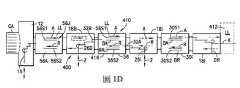
參考圖1D,一例示性的處理工具410的一沿著該直線排列的轉送室416的縱長軸線X所取的示意圖被示出。在一如圖1D所示的態樣中,該工具界接區段12可被代表性地連接至該轉送室416。在此態樣中,該界接區段12可界定該工具轉送室416的一端。如圖1D中所見,該轉送室416可例如在一和該界接區段12相反的一端具有另一工件入口/出口站412。在其它態樣中,用來將工件插入該轉送室或從轉送室移走的其它入口/出口站可例如被設置在該工具轉送室416的兩端之間。在被揭露的實施例的一個態樣中,界接區段12及入口/出口站412可允許將工件從該工具載入及從工具移出。在其它態樣中,工件可從一端被載入該工具並從另一端被移出。在一態樣中,該轉送室416可具有一或多個轉送室模組18B,18i。每一室模組能夠維持一被隔離的、受控制的或被密封的氣氛(如,氮氣、潔淨空氣、真空)。如之前提到的,形成該轉送室416的轉送室模組18B,18i、負載鎖定室模組56A,56B及工件站如圖1D所示地只是舉例性的,在其它態樣中,該轉送室可以有更多或更少的模組用任何所想要的模組組態來設置。在一態樣中,站412可以是一負載鎖定室。在其它態樣中,一負載鎖定室模組可被設置在端入口/出口站(類似於站412)之間或毗鄰的的傳送室模組(類似於模組18i)可被建構來如一負載鎖定室般地操作。同樣如之前提到的,轉送室模組18B,18i具有一或多個室設置於其內之相應的運送設備26B,26i。該各別的轉送室模組18B,18i的運送設備26B,26i可合作以提供該被直線地排列的工件運送系統420於該轉送室內。在其它態樣中,該等轉送室模組18B可被建構來允許任何適合的運送台車(未示出)沿著該直線式的轉送室416的長度的至少一部分移動於轉送室模組18B之間。將可被瞭解,該運送台車900可包括任何安裝於其上之適合的運送設備且實質地類似於那些描述於本文中的運送設備。如圖1D中所示,在一態樣中,該運送設備26B的手臂可被設置來提供被稱為快速交換晶圓的結構,其允許該運送在一撿取/放置位置快速交換晶圓,這將於下文中詳細描述。該運送手臂26B可具有一適當的驅動區段,用以用一比傳統的驅動系統更簡化的驅動系統來提供每一手臂三(3)維度的自由度(如,以Z軸運動提供繞著肩及肘接頭的獨立轉動)。在其它態樣中,該驅動區段可提供該手臂比三維度更多或更少的自由度。如圖1D中所見,在一態樣中,模組56A,56,30i可被間隔地(interstitially)設置在轉送室模組18B,18i,之間且可界定適合的處理模組、負載鎖定室、暫存站、精密測量站、或任何其它所想要的站。例如,該等被間隔地設置的模組,譬如負載鎖定室56A,56及工件站30i,每一者都具有固定不動的工件支撐件/架子56S,56S1,56S2,30S1,30S2,它們可和該運送手臂合作,用以沿著該轉送室的直的軸線X將工件運送於轉送室的長度上。舉例而言,工件可被界接區段12載入到該轉送室416。工件可被該界接區段的運送手臂15放置在負載鎖定室模組56A的支撐件上。在該負載鎖定室模組56A中的工件可被模組18B中的運送手臂26B移動於負載鎖定室模組56A和負載鎖定室模組56之間,且以一類似且連續不斷的方式被(模組18i中的)手臂26i移動於負載鎖定室模組56和工件站30i之間及被模組18i中的手臂26i移動於站30i和站412之間。此過程可整個被顛倒或部分被顛倒,用以將工件移動於相反方向上。因此,在一態樣中,工件可沿著X軸被移動於任何方向上且沿著該轉送室被移動至任何位置且可被載入到和該轉送室聯通之任何所想要的模組(處理模組或其它模組)或從該等模組移出。在其它態樣中,該等具有靜態的工件支撐件或架子之被間隔地設置的轉送室模組可以不被轉送室18B,18i之間。在被揭露的實施例的這些態樣中,相鄰的轉送室模組的運送手臂可從一末端作用器(end effector)或一運送手臂直接(或透過使用一暫存站)將工件傳遞至另一運送手臂的末端作用器來將工件移動通過該轉送室。該等處理站模組可藉由各種沉積、蝕刻、或其它類型的處理來在該基材上操作,用以形成電路或其它類型的結構於該基材上。該等處理站模組被連接至該等轉送室模組,用以允許基材從該等轉送室被送至該等處理站,且反之亦可。具有和圖1D中所示的處理設備的一般特徵類似的處理工具的一個例子被描述在先前藉由參照而併於本文中的美國專利申請案第11/442,511號中。1D, an
現參考圖2A-2E,一處理工具200(如,那些描述上文中的處理工具)的一部分被例示。該處理工具200可包括一環境受控制的界接模組201(其在本文中被稱為“界接模組”)、一轉送室202、一負載鎖定室203及一載入埠模組204。該載入埠模組可以是任何適合的載入埠模組,譬如描述於美國專利第6641348號、第6501070號、第6815661號、第6784418號、第6765222號、第6281516號及2005年7月11日提申之美國專利申請案第11/178,836號(美國公開案第2007/0009345號)中的載入埠模組,它們的揭露內容藉由此參照而被併於本文中。在一態樣中,該載入埠模組可被建構來支撐並耦合至一前開式晶圓傳送盒(FOUP)、一標準機械式界面(SMIF)盒或任何其它適合的可攜式基材轉送/儲存容器211,其如上文所述地被建構來容納任何適合的大小及形狀的基材。Referring now to FIGS. 2A-2E, a portion of a processing tool 200 (such as those described above) is illustrated. The
該轉送室202可以是任何適合的轉送室,其被建構來維持任何適合的內部氣氛。在一態樣中,該轉送室202可被建構來維持一真空於該室內,該基材轉送/儲存容器211亦被建構來維持一真空於其內並直接和該轉送室202的真空環境直接實質地界接。在其它態樣中,該轉送室202可被建構來將該轉送室202內的該氣氛循環於例如一大氣環境和一真空環境之間。該轉送室202可包括一或多個可密封的開口202S,用來將該轉送室耦合至任何適合的半導體處理模組,譬如該界接模組201、另一轉送室、該負載鎖定室203及/或該載入埠模組204。該轉送室202亦可包括任何適合的基材傳送器,譬如基材傳送器202T,用來將基材傳送於和該轉送室202相耦合的一或多個基材處理模組之間。在一態樣中,該基材傳送器202T可以是一選擇性順從關節型機器手臂(SCARA),其具有例如至少一上手臂202TU、至少一前手臂202TF及至少一被建構來固持至少一基材220的基材固持器或末端作用器202TE。在其它態樣中,該基材運送器可以是一蛙腳式手臂、雙對稱運送手臂、滑動連桿運送手臂、不等長連桿基材運送手臂或任何其它被建構來將基材從一基材固持位置運送至另一基材固持位置之適合的運送器。The
該負載鎖定室203可以是任何被建構來將該負載鎖定室的內部環境循環於任兩個環境(譬如,該轉送室202的內部環境和一處理模組(未示出)或另一耦合至該負載鎖定室203的轉送室)之間之適合的負載鎖定室。可被瞭解的是,該負載鎖定室可包括一或多個可密封的開口203S,其被建構來將該負載鎖定室203以類似於上文所描述的方式耦合至任何適合的基材處理模組。The
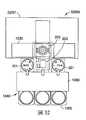
亦參考圖5A-8C,該界接模組201可被建構來和任何適合的基材載具(譬如,環境受控制的基材盒210(其在本文中被稱為“基材盒”))相界接,這將於下文中作更詳細的說明。該界接模組201可包括特徵結構(這將於下文中描述),用以和該基材盒210對接並打開及關閉該基材盒。應指出的是,雖然該基材盒210如所示地是一下開式基材盒且該界接模組201如所示地被建構來打開及關閉該下開式基材盒,但在其它態樣中,該基材盒可以是包含描述於本文中的特徵結構之前/側開式基材盒或一上開式基材盒且該界接模組可被適當地建構並包括描述於本文中的特徵結構,用以打開並關閉該基材盒。該界接模組201可包括一框架,其具有一形成一或多個內部室的外殼201H。應指出的是,雖然該界接模組201被顯示為單一基材盒界接模組,但在將於下文中描述的其它態樣中,該界接模組可以是多埠式界接模組,其具有一由該等盒界接埠的每一埠所共用的內部室或用於每一盒界接埠之分離的內部室。在一態樣中,該內部室可以是一真空室,而在其它態樣中,該部室可被建構來維持任何適合的環境。該外殼可包括一或多個可密封的開口201S,其被建構來將該界接模組201耦合至其它半導體處理模組(譬如,描述於本文中的半導體處理模組)及/或一或多個觀看埠201VP以允許視覺檢視該外殼201H的內部。將可被理解的是,該外殼201H及其它描述於本文中的半導體處理模組可在該外殼201H的一單一側上具有多個以垂直地疊設及/或水平並排的方式設置的開口,用以將任何適當數量的處理模組耦合至該外殼201H並可彈性地將該界接模組整合至多種設備組態中。Referring also to FIGS. 5A-8C, the
在一態樣中,該界接模組201包括一埠板209及一升降器730,其可被建構來打開該基材盒210。該升降器730可被耦合至該埠板209的至少一部分,譬如耦合至界接模組門209D,用以將該界接模組門209D移動於例如箭頭799所示的方向上,用以打開及關閉該基材盒210。該升降器包括任何適合的線性致動器530A,其可以用任何適當的方式(譬如,藉由一風箱式軟管730B)來和該外殼201H的內部隔離以實質地防止微粒和有機污染物進入到該外殼201H的內部。在一態樣中,該界接模組門209D可包括一盒界面209DP及一升降器界面209DE,它們可相對於彼此移動。例如,該盒界面209DP和該升降器界面209DE可用任何適合的方式(譬如,用彈性件752)來保持彼此間隔開的關係。該升降器730可被耦合至該盒界面209DP,使得當該線性致動器530A被操作時,該埠板係被動地操作。例如,該盒界面209DP和該升降器界面209DE之間來自於該升降的操作的被動性相對運動可造成門閂銷520、門閂致動器530或該埠板的任何其它特徵結構的操作,這將於下文中被描述。在其它態樣中,該盒界面209DP和該升降器界面209DE可具有一單一的一件式構造且該埠板的特徵結構可用任何適合的方式予以操作。In one aspect, the
在一態樣中,該埠板209可包括例如一或多個埠密封件590、一埠門密封件591(如,用來密封該埠門209D和一埠緣760R之間的一開口201X(參見圖7),該埠門和該埠緣形成該界接模組201的一用於傳送基材進入該外殼201H的內部的該開口201X)、一盒夾500及一門閂致動器530,該等構件的一或多者可設置在該界接模組門209D上及/或該埠板209的任何其它適合的位置。該埠板209亦可包括一盒存在感測器580(參見圖5B)、狀態指示器610、清洗埠600的一或多者、一或多個門感測器520及界接模組門209D的一門存在感測器700、這些構件的一者或多者可被設置在該界接模組門209D上及/或該埠板209的任何其它適合的位置。In one aspect, the
亦參考圖3D,該埠密封件590可被設置在該門209D或該埠板209的盒支撐表面760的一者或多者上,用以形成該盒支撐表面760和該基材盒210的下表面210B之間的密封件。應指出的是,該埠密封件590及/或該盒夾500可形成一多餘的密封系統,其中至少一密封件590被設置在例如一水平的平面上及另一其它的密封件(如,盒夾500)被設置在一實質垂直的平面上(如,該等密封件被設置在實質正交的平面上),環繞該基材盒210的周圍。在一態樣中,埠密封件590可包括被設置在該門209D的周邊的周圍,用來密封一介於該埠板209的門209D和該基材盒210的一門210D(參見圖3A-3C)之間的界面之任何適合的密封件590A。密封件590亦可包括被設置在該盒支撐表面760的周邊的周圍用來密封一介於該盒支撐表面760和該基材盒210之間的界面之任何適合的密封件590B。在其它態樣中,該埠密封件590可包括任何適當數量之具有任何適當構造的密封件。該埠密封件590可被隱藏起來(recessed)或以其它任何適合的方式附著在該門209D、該盒支撐表面760、該外殼210H或該門210D的一者或多者內或上。Referring also to FIG. 3D, the
該盒夾500可沿著該埠板209的一下凹的部分209R(參見圖5A)的周邊被設置,該基材盒210被置於該埠板內。在其它態樣中,該埠板209不具有一下凹的區域。該盒夾500可以是任何適合的夾鉗,用來將該基材盒210的外殼210H(參見圖3A-3C)固持在該埠板209上。在一態樣中,該盒夾500可以是一可膨脹的夾鉗,其被建構來抓住該基材盒210的外殼的周邊並與之形成一密封。該盒夾500可用任何適合的方式(譬如,藉由任何適合的幫浦(未示出))來使其膨脹。在其它態樣中,該盒夾可包括任何適合的夾子、凸輪、桿或任何其它適合的可鬆開的固定的或可活動的夾鉗機制。The
該門閂致動器530可包括任何適合的握爪,用來抓握住該基材盒門210D的一相對應的特徵結構(譬如,柱子310(圖3A)),這將於下文中描述。在一態樣中,該門閂致動器530可包括一用來讓該門閂致動器和該柱子310對準的銷530P,及一或多個用來抓住該柱子310的指件530L。在一態樣中,該等指件530L被可樞轉地耦合至該銷530P及該埠板209的一表面的至少一者,使得當該銷530P被移動於箭頭798所示的方向上時,該等指件530L會樞轉以抓握住該柱子310並移動該基材盒門抵住該界接模組門209D以形成一介於該基材盒門和該界接模組門209D之間的密封,這將於下文中更詳細地描述。一穿通導管770亦可被形成在該界接接模組門209D中以提供用於該門閂致動器530的致動的任何適合的感測器及/或用於在該等指件530L抓握住該柱子310時感測的感測器。在其它態樣中,該門閂致動器530可以是該升降器730的一部分,使得當該線性致動器530A移動該升降器時,該等指件530L被促動,用以用任何適合的方式(譬如,被該銷530P的直線運動)轉動以抓握住該柱子310。The
該盒存在感測器580(圖5B)可包括一發送器580T及一接收器580R,用以用任何適合的方式感測該基材盒210存在於該埠板209上。雖然該盒存在感測器580被例示為具有在分開的殼內的一發送器580T及一接收器580R,但在其它態樣中,該發送器及接收器可被設置在一共同的殼內。在一態樣中,該盒存在感測器可以是一非接觸式感測器,譬如一反射式感測器、一穿透光束感測器或任何其它光學的、電容的或無接觸的感測器。在另外其它的態樣中,該盒存在感測器580可以是任何其它適合的感測器類型,譬如接觸式感測器。該門存在感測器700可例如被設置在該界接模組門209D上,用以例如用任何適合的方式偵測緊鄰該界接模組門209D之該基材盒210的存在。一或多個門閂感測器520亦可被設置在例如該界接模組門209D上,用以被動地將該基材盒門210D(圖3A-3C)從該基材盒外殼210H(圖3A-3C)上鬆脫開(這將於下文中描述)及/或偵測該閂鎖何時被釋開。The box presence sensor 580 (FIG. 5B) may include a
該等狀態指示器610可被設置在該界接模組201上的任何適合的位置。在一態樣中,該狀態指示器可被設置在該埠板209的一表面上。如圖6B中所見,該等狀態指示器610可包括一或多個視覺指示器610A,610B,610C,610D,610E,它們將該界接模組201的操作狀態傳達給操作者。應指出的是,該等狀態指示器610以及該界接模組201的各式感測器及驅動器可被可操作地連接至一或多個控制器,譬如控制器1091(參見圖1A)。該控制器接收來自該等各式感測器及驅動器的訊號並提供相應的訊號給該等狀態指示器610以提供視覺的狀態指示。The
該界接模組201亦可包括一或多個清洗埠600(參見圖6A及8C)。在此態樣中,該清洗埠600被設置在該盒支撐表面760上,以用於該基材盒210的氣體/流體儲槽或室390(圖3C)的清洗(如,排空)或填充(重新填充或填充),這將於下文中描述。在一態樣中,該氣體儲槽390的清洗可在把該界接模組201及/或該基材盒210的一者或多者抽空至真空時被自動地實施。在其它實施例中,該氣體儲槽390的排空或填充可在任何適合的時間被實施。該界接模組201亦可包括其它用於沖洗或清洗介於例如該埠板209/埠板門209D和該基材盒210之間的間隙或被密封的區域的流體埠口。例如,該埠板209可包括一間隙沖洗供應埠810(圖8B)及一間隙沖洗排放埠811(圖8B),用來沖洗例如介於該埠板209和該基材盒210之間的間隙及/或一介於該界接模組門209D和該基材盒210的門之間的間隙。這些間隙可在該界接模組門209被打開之前用任何適何的氣體(譬如,氮氣或其它乾淨的乾空氣)來沖洗。該被包陷在介於該埠板209和該基材盒210之間的體積及/或一介於該界接模組門209D和該基材盒210的門之間的間隙亦可被抽空至例如等於該基材盒210內部的壓力的真空壓力以用於該基材盒門210D的移除。這將方便微粒的去除且藉由在真空中打開該基材盒210,微粒的產生可以是在該基材盒210內的基材的下游處且經由該界接模組201的排放埠811被排出。圖8D是該界接模組外殼201H的底部的示意圖。如圖中所見,有用於清洗埠600的穿通道(pass through)、沖洗氣體供應埠810及沖洗氣體排放埠811。一用來將該外殼201H的內部抽吸降壓的真空粗抽閥(roughing valve)877及一通氣閥878亦可被設置。The
該界接模組門209D亦可包括一或多個運動耦合銷(kinematic coupling pins)510,511,512,用來將該基材盒210相對於該埠板209定位於一預定的位置。該等運動耦合銷510,511,512可以是任何適合的銷,其被建構來和該基材盒210的任何適合的匹配/定位特徵結構301,302,303相界接。該等運動耦合銷510,511,512可例如用任何適合的方式(譬如,用任何適合的軸承710及密封件711)被固定至該門209D,使得該等運動耦合銷510,511,512可相對於盒界面209DP移動,這將於下文中描述。The
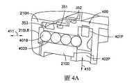
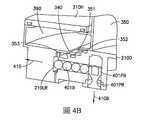
現參考圖3A-4B,如上文中提到的,該基材盒210包括一外殼210H及一門210D。該外殼210H可形成一壓力容器且具有任適合的形狀及尺寸,譬如,一圓柱形或圓形的截面且該外殼210H的上表面210T可以圓頂形或實質的球形,用以利用箍環應力來減小該外殼210H必要的壁厚及該基材盒210的重量。在一態樣中,該基材盒210具有一內部空間350,其具有一環境,它可以和與其相連接(例如,透過該界接模組201相連接)的處理工具的任何適合的部分具有一共同的氣氛。透過該界接模組201而形成在該基材盒210和該處理工具之間的該通路或通道可被稱為一無塵通道(clean tunnel),它將該基材盒實質地直接連接至該處理工具,就如同描述於2008年5月19日提申之名稱為“Side Opening Unified Pod”的美國專利申請案第12/123,391號中的結構,該申請案的內容藉由此參照而被併於本文中。例如,該無塵通道提供從該基材盒210的內部環境、經過介於該基材盒210和該界接模組201之間的界面及到整個界接模組和該處理工具的處理區段都完全相同的潔淨度(即,整個處理工具和界接模組都相同)。該無塵通道可被自由地關閉(譬如,當基材盒從該界接模組被取出時)及打開而不會降低該無塵通道的潔淨度。在如圖2A,2B及11-30圖所示的態樣中,該基材盒對該界接模組的界接亦可被設置成可以讓該基材盒和該處理工具直接整合在一起,而不受界接之前該基材盒內的環境影響。因此,在例如被例示在圖2A,2B及11-30中的實施例的態樣中,該基材盒210可以和具有不同或不相似的環境(如,低真空到高真空、乾淨空氣環境到鈍氣環境、或乾淨空氣到真空)的處理工具界接並與之直接整合,然後直接傳送於具有不同的不相似環境且再和該等工具相界接及相整合的工具之間。因此,一在一具有環境受控制的工具內的基材可被該處理工具的任何適合的機器人從該工具的處理區段經由該無塵通道直接轉送至該基材盒210內、該基材盒210被直接運送至可能具有一不相似的/不同的環境受控制的另一工具的界接模組並與之界接、及該基材藉由任何適合的機器人被直接轉送通過該無塵通道且不會讓該另一處理工具的該受控制的環境變差,該無塵通道現在係被界定在該另一處理工具到一處理區段之間。事實上,該基材盒對和與該基材盒210界接的界接模組整體可被視為界定了一外部的負載鎖定室或載具鎖定室。在一態樣中,該界接模組埠板可包含一蓋子,它可被任何適合的致動器及/或機構升高、降低、旋轉、或在定位被樞轉。該蓋子提供該界接模組環境隔離及控制,用以允許該界接模組在沒有該基材盒時可以如一環境受控制的穿通道般地作用。在一態樣中,該埠板或門可在晶圓堆被降低進入到該界接模組內部空間之後被轉動。該晶圓堆可被轉動,用以和該等相匹配的轉送機器人對準以允許該基材盒自動化,用以在一不同於該被要求的晶圓堆方位的方位之下載入該基材盒。3A-4B, as mentioned above, the
在一態樣中,該外殼210H可被建構來容納5片基材,而在其它態樣中,該外殼210H’可被建構來容納25片基材或任何其它適合數量的基材,譬如3片基材或甚至是1片基材。該外殼可用任何適合的材料來建造,譬如高結構模數的材料、金屬或金屬合金(如,鋁,不銹鋼、鈦)、塑膠、複合材料、或它們的組合,並形成一內部空間350,其例如在該外殼的開口350X被該門210D封閉時(例如,在該基材盒210的運送或儲存期間)及在該外殼210H被耦接至該界接模組201時係被維持在真空壓力環境或鈍氣環境。該外殼210H係用任何適合的方式(譬如,用強化肋等等)予以結構地建造,用以當該內部例如是在真空壓力下時支撐施加於該外殼上的內部的負荷。如上文中提到的,該外殼210H亦可包括一氣體(或其它流體)儲槽或室390。在其它態樣中,該氣體室390可被設置在該門210D中。在另外的其它態樣中,該外殼210H和該門210D這兩者皆可包括一氣體室390。該室390可被建構來容納任何適合的氣體,譬如氮氣或其它鈍氣。該室390或它的任何部分可和該外殼210H一體地形成或用任何適合的方式耦合至該外殼。該室390可在該基材盒210的運送或儲存期間或當該基材盒210被對接(docked)至一界接模組時被填充或被注滿。例如,該基材盒210的一外部埠口(它和一個站(如,一界接模組、儲存站、及/或運送系統站)上的適合的匹配埠口相對接)可被用來作為提供一氣體/流體至該室390的填充供應埠。在一些例子中,此一系統可允許該室390的體積被減小,因為只需要攜載在被預期的運送時間所需的氣體/流體體積以及伴隨之在從一個站移動至下一個站期間被預期的滲漏率所需的氣體/流體體積。因此,該室390的體積及該基材盒的覆蓋面積(footprint)可被減小或最小化。在一態樣中,該室390可在和該界接模組201相界接時透過埠600被填充。該室390可延伸在該外殼開口350X的周邊周圍並容納可例如經由一從該室390延伸至一介於該外殼210H和該門210D之間的密封界面342(圖3D)的路徑340被釋入到該內部空間350的任何適合的體積的氣體。該路徑340可包括一止回閥或任何其它適合的閥以允許氣體/流體從該室390流出以及氣體/流體注滿該室390的一預定的方向。在一態樣中,氣體/流體通過該路徑340的流動可在該基材盒210被對接(docked)或和該界接模組201界接時被阻擋。在其它例子中,氣體/流體通過該路徑340的流動在該基材盒210被對接(docked)或和該界接模組201界接時可以不被阻擋且該氣體/流體可被允許從室390被排空。在此一例子中,室390可在從該界接模組201被取出之前被填充一氣體/流體。在一些態樣中,在任何被給定的填充期間被填充至室390中的特定氣體/流體及/或被填充至室390中的特定氣體/流體的壓力係根據在該處理流程的每一步驟的裝置處理要求來加以選擇。例如,被填充至室390中的該氣體/流體可依據和將被載入或已被載入基材盒210內的基材的相容性來加以選擇。在一些態樣中,一第一氣體/流體被填充至室390中以用於該基材盒210的一第一運送,在室390內的該第一氣體/流體在和該界接模組201對接的時候或之後被釋出,及一第二氣體/流體被填充至該室390中以用於該基材盒210的一第二運送。In one aspect, the
應指出的是,該路徑340及該室390可提供一冗餘的系統(redundant system),如果該基材盒210正經歷一滲漏且板上(on-board)室壓力(如,在該內部空間350內的壓力)已降至一預定的低壓低限值以下的話,則譬如致動該路徑中的閥或以其它方式從該室釋出該氣體/流體並通過該路徑340,使得該氣體/流體流可經由該冗餘的系統從該室390流入該基材盒210的內部空間350。此冗餘的系統(即,只有在滲漏時氣體/流體才會被釋出的系統)可讓該室390的體積被減小,使得該基材盒的覆蓋面積亦被減小或被最小化。在另一態樣中,如果該板上室壓力(即,在該內部空間350內的壓力)已降至一預定的低壓低限值以下的話,則在一配接至界接模組、儲存站、或運送系統上的一適合的匹配埠口的外部埠口內的閥可被致動,用以經由路徑340從該室390提供一連續的氣體/流體供應至該內部空間350或將該室390內的氣體/流體注滿(如,填充或以其它方式再填充/填充)至一特定的壓力。It should be noted that the
應指出的是,在該室390及該路徑340內的該氣體(或其它流體)可形成一流體障礙密封件,其實質地包圍該等門密封件351,352的一者或多者。該流體障礙密封件可具有一氣氛,其不同於在該內部空間350內的氣氛且以一適合方式和該內部空間350內的氣氛隔離開來,這將於下文中描述。在一態樣中,該流體障礙密封件可以是一加壓式密封件,其被設置在該內部空間350的氣氛和該基材盒210外部氣氛之間。如上文中提到的,在一滲漏的情形中,流體從該室390經由該路徑340被汲取至該基材盒210的內部空間350中。這實質地防止任何周圍的晶圓廠空氣(其包含了諸如微粒、濕氣或氧氣等污染物)被引入到該內部空間350中。在一些態樣中,該被填充入到該室390內的氣體/流體係根據在該處理流程的每一步驟的裝置處理要求來加以選擇。例如,在正常的情況下,密封件351,352的狀態良好(即,沒有滲漏),該流體會留在該室390及路徑340內且不會進入到該內部空間350中。It should be noted that the gas (or other fluid) in the
在一態樣中,該外殼210H可包括任何適合的特徵結構環繞在該外殼的周邊,用來和任何適合的夾緊裝置(如,固態夾鉗、可活動的機械式夾鉗等等)界接,例如和該界接模組201的盒夾鉗500界接,用以將該基材盒210固持在該界接模組201上。應指出的是,將該基材盒210固持於該界接模組201上的夾鉗可提供一用來壓擠該埠密封件590的力。該外殼亦可包括任何適合的把手,譬如頭定式運送把手349,用以方便自動及/或手動的基材盒210運送。In one aspect, the
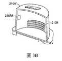
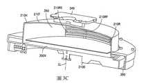
在一態樣中,該門210D包括一或多個基材固持支撐件210RS(如,一架子210R),其被設置成垂直的疊架。該架子210R可用任何適合的方式被安裝至該門210D或和該門210D一體地形成,使得當該門210D從該外殼210H被取下時,該等基材亦一併從該外殼210H被取出(如,該等基材和該門一起被運送)。該架子210R及該架子和該基材接觸的部分可用任何適合的材料來建造,譬如PEEK(聚二醚酮)或BKM材料。在一態樣中,該等基材固持支撐件210RS可包括一後擋止件210RP,使得該等被固持在每一支撐件上的基材被侷限住。在另一態樣中,一基材護圍(retainer)210RR可被安裝至該外殼210H且例如被該界接模組201致動,使得該護圍的致動(actuation)可將該等基材保持在它們在該架子210R內各自的支撐件210RS上。該等基材護圍210RR可對該架子210R內的每一片基材施加一力,該力將每一基材壓頂或以其它方式迫抵該後擋止件210RP,用以在基材盒210(及其內的基材)的運送期間實質地防止該基材盒210內的基材移動。在其它態樣中,該護圍的致動可以是垂直的且提供一垂直的力於該架子內的每一基材上,該力將基材壓擠或迫擠至一圓錐形支撐件的座位。如上文中提到的,該門210D的外表面可包括一或多個適合的配接/定位(如,運動耦合的)特徵結構301,302,303,用來和該界接模組201的運動銷510,511,512相界接。該門的該外表面亦可包括一柱子310,其被建構來和該門閂致動器530界接。In one aspect, the
如上文中提到的,當該門將該外殼210H的開口350X密封時,該外殼210H的該內部空間350可被維持在真空壓力。在一態樣中,門210D可例如藉由該外殼210H內部的真空和基材盒210外面的大氣壓(或其它壓力)之間的差別壓力而被密封地保持緊抵該外殼210H。該差別壓力可提供一力,使得被固持於該架子210R內的基材的重量受到支撐並壓擠設置在該門210D和該外殼210H之間的密封件,譬如密封件351-353(這將於下文中描述)。在一態樣中,該基材盒210可包括一門閂400(圖4A及4B),用以在被密封於該外殼210H內的真空被喪失的情況中實質地防止門210D和該外殼210H分開。應指出的是,在此態樣中,該門閂400可以不被用來將該門210D密封至該外殼210H,而是該門閂400只是在該外殼210H內的壓力喪失掉的情況中維持該門210D相對於該外殼210H的位置。在其它態樣中,該門閂400可被用來用任何適合的方式將該門210D密封至該外殼210H。在一態樣中,該門閂400可以是一球鎖機構,而在其它態樣中,該門閂400可以是任何適合的閂鎖件。該門閂包括一柱塞401P及一或多個球401B,其被至少部分地是置在該門210D內。該柱塞可移動於該路徑402P內箭頭410所示的方向上,而該等球401B則可移動於該路徑402B內箭頭411所示的方向上(路徑402B和路徑402P相交)。該柱塞401P包括一球接觸區域401PB及一凹陷區域401PR且可用任何適合的方式(譬如,用一彈性件)偏動於箭頭410B所示的方向上。當在如圖4B所示之該被偏動的或被鎖定的位置上時,該柱塞401P用該球接觸區域401PB和該等球401B接觸,用以將該等球迫擠於箭頭411U所示的方向上,使得至少一球被置於該凹部210LR內,該凹部被設置在該外殼210H內,用來將該門210D鎖合至該外殼210H。當在圖4A所示的縮回或解鎖的位置時,該等球被允許移入到該柱塞401P的凹陷區域401PR內並離開該凹部210LR,用以將該門210D和該外殼210H解鎖。在一態樣中,一感測器可被設置在該門閂上,用以偵測該門是否被適當地置於該界接模組上、該門在先前的站是否被適當地安裝、或該門在重新載入該基材盒的期間是否被適當地更換。例如,該球鎖柱塞的延伸高度可被用來取得此資訊。As mentioned above, when the door seals the
介於該門210D和該外殼210H之間的密封件351及352(它們是真空密封件)可具有一冗餘的配置。一氣體儲槽密封件353亦可被提供。在一態樣中,該密封件352可以是一內密封件,它在它的一側具有該內部空間350的氣氛。該氣體儲槽密封件353可以是一外密封件,其在密封件353的一側具有一外面的氣氛(如,在該基材盒210的外面的氣氛)及在該密封件353的相反側的該流體障礙的氣氛。該密封件351可以是一中間密封件,其具有在該密封件351的一側的該流體障礙密封件的氣氛。形成在密封件351和352之間的區域可形成一空隙,其具有任何適合的氣氛,該氣氛可以和該內部空間350的氣氛及該流體障礙密封件的氣氛的一者或多者相同或不同。該中間密封件351可將該流體障礙密封件和該內密封件352隔離開,而密封件351,352中的一者或多者可將該流體障礙密封件和該內部空間350隔離開。應指出的是,雖然密封件351-353被顯示為下凹至該門210D內,但在其它態樣中,該等密封件可被下凹至該門210D及外殼210H的一者或多者中或以其它方式固著於其上。亦應指出的是,該等密封件351-353可具有一圓形的形狀(如,圓形密封件形狀),而在其它態樣中,該等密封件可具有任何適合的密封形狀。密封件351,352的冗餘性可提供抵擋受損的密封件及/或該密封區域內的微粒的防護,它可防止該門210D和該外殼210H的配接表面之間的正接觸。密封件351,352可被置於兩個不同的平面P1,P2上且密封表面可被下陷用以例如保護密封表面不受損傷。雖然平面P1,P2被顯示為實質地環繞該基材盒210的周圍之不同的水平表面,但在其它態樣中,該等密封件的一者或多者可被置於一垂直的平面上。應指出的是,將密封件351,352置於不同的平面上可提供密封件351,352的一者或多者不會和其它物件或晶圓機器人相撞的保護,該相撞會撕裂或以其它方式損壞該內密封件352。該氣體儲槽密封件353可相對於該基材盒210的中心線CL被設置在密封件351,352的一者或兩者的外面。在密封件351,352兩者都失效的情況中,該氣體儲槽密封件353可提供一無塵環境於該內部空間350內,因為氣體從該氣體儲槽390被釋入到該內部空間350中。在一些態樣中,密封件353被密封件351,352更順服(compliant)且以一適合的方式被放置,用以在該門和該外殼相配接時提供和該外殼上的一相匹配的密封表面的內部接觸。在此等態樣中,密封件353可提供適當的順服性以開始一真空密封並允許一真空力作用於該基材盒門上以提供用於密封件351,352的壓擠力並允許密封件351及352使用對於真空應用而言是所想要之較不順服的材料。可被瞭解的是,任何適合的感測器都可被設置在該基材盒上的任何適合的位置,用以監測該內部空間350及/或氣體儲槽390內的壓力並在滲漏或壓力喪失被偵測到的時候提供警告或其它警報給操作者(如,透過控制器1091-圖1A)。如果一滲漏被偵測到的話,則該控制器1091或操作者可將基材盒210引導至一預定的位置以進行診斷及/或將該基材盒210引導至一站,用以將氣體/流體填充至室390內。The
應指出的是,用於每一密封件351-353的匹配表面可以是凹陷的表面。在一態樣中,密封件351-353被設置在門210D上,該外殼210H可包括凹陷的區域351R-353R(圖3D),該等密封件351-353在該等區域內和該外殼210H界接。在一或多個密封件被設置在該外殼210H中的其它態樣中,該門210D可包括該等凹陷的區域。在另外其它的態樣中,該一或多個密封件351-353及該等凹陷的區域351R-353R可被適當地設置在該門210D及該外殼210H的任一者上。It should be noted that the matching surface for each seal 351-353 may be a concave surface. In one aspect, the sealing elements 351-353 are disposed on the
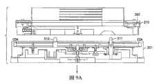
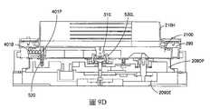
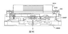
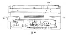
現參考圖4A,4B,7,9A-9F及10,該基材盒210對該界接模組201的一示範性對接或裝載將被描述。該基材盒210被移動至該界接模組201且用任何適合的方式和該等運動銷510-512配接(圖10,方塊5000;圖9A-9B)。該盒存在感測器580(圖5B)可例如通知該控制器1091(圖1A)該基材盒的存在。如上文中提到的,該等運動銷510-512被可活動地安裝至該升降器界面209DE,使得當該升降器730被降低時,該等運動銷510-512相對於該盒界面209DP被縮回(圖10,方塊5001;圖9C),使得該外殼210H和該埠密封件590接觸(圖5A)。該基材盒外殼210H可用任何適合的方式(譬如,用盒夾500)而被夾鉗固定至該埠板209(圖10,方塊5002)。至少該介於該基材盒門210D和該盒界面209DP(如,界接模組門)之間的空間(如,埠門間隙)可被排空或抽吸降壓(圖10,方塊5003)。在一態樣中,當一基材盒沒有被完全地被對接至該界接模組201上時,一乾淨的乾空氣的低壓流可經由該埠門間隙被散布並清洗密封件590A及590B。這乾淨的乾空氣的低壓流可防止來自於周圍的工廠環境的微粒停在該密封件上並造成滲漏。此外,該正壓實質地防止微粒停留在該埠門間隙且稍後被沉積到該界接模組201及/或基材盒210的內部無塵真空空間中。該乾淨的乾空氣的流速可以很低,用以避免紊流進入到周圍的工廠環境中。當該基材盒出現在該等運動銷上時,形成在該埠門和基材盒下表面之間的水平間隙可將該乾淨的乾空氣流水平地引導通過該等密封件且隨著基材盒下降,該間隙亦會縮小,這可提高該乾淨的乾空氣的流速以逐出任何微粒。在其它態樣中,該外殼210H(圖5A)的內室可被抽吸降壓。該基材盒門210D可被取下(圖10,方塊5004;圖9D-9F),升降器730(圖7)可被進一步降低,使得該升降器界面209DE的運動造成指件530L夾住基材盒門210D的柱子310。該升降器界面209DE的運動亦可造成門閂銷520和該鎖401的柱塞401P嚙合,使得該柱塞401P被移動至該縮回的位置(圖4A),用以如上文所描述地釋開該鎖401。該基材固持器(如上文所述者)亦可被釋開,用以將基材從該外殼210H釋出。在此處理期間,該氣體儲槽390可用任適合的方式予以密封,用以將該氣體/流體保存於其內或在儲槽390內的該氣體會例如被排出到該界接模組201的內部中或該基材盒的內部中,該儲槽390稍後例如在稍後的基材盒門關閉期間被重新填充氣體/流體。應指出的是,介於該盒界面209DP和該升降器界面209DE之間的相對運動可被侷限於一預定的運動量,使得當該鎖401被解鎖且該柱子310被該門閂機構530抓住時,該盒界面209DP和該升降器界面209DE一起移動,用以將該基材盒門210D從該外殼210H上取下。該基材盒門210D可被該升降器730用任何適合的方式移動,使得該架子210R上的一所想要的基材990沿著一所想要的基材轉送平面STP被放置,使得該基材可例如被基材運送器202T從該架子210R上被取下以運送至和該界接模組201相連接的任何適合的處理模組。Referring now to FIGS. 4A, 4B, 7, 9A-9F and 10, an exemplary docking or loading of the
應指出的是,在該基材盒210的內部空間350和該界接模組201的內部之間會有一壓力差。介於該基材盒210和該界接模組201之間的界面可被建構來以任何適合的方式,譬如透過動態壓力平衡,來容納此壓力差。例如,該升降器730可例如被任何適合的控制器(譬如,控制器1091)控制,使得該升降器730形成一電子釋壓閥。例如,當該界接模組201的內部被抽泵降壓至真空時,在某些點的壓力將跨越(cross-over)該基材盒210內部的真空壓力且該埠門209D及該基材盒門210D將例如在來自於該正壓差的該力的作用下推開該埠門209D及該基材盒門210D。當該基材盒門210D打開時,該基材盒210的體積和該界接模組201的體積即流體連通,允許該基材盒210內部的壓力及該界接模組201內部的壓力平衡,實質地消除這兩個體積(該基材盒的內部及該界接模組的內部)之間的壓力差。此壓力平衡可以在沒有事先知道該基材盒210內部的壓力及/或該界接模組201內部的壓力之下被實施,使得壓力感測器在該基材盒210中可以是不被需要的。It should be noted that in the
將該基材盒210從該界接模組201卸下可用一和上文所述用來將該基材盒210裝載到該界接模組201上的方式實質相反的方式來實施。在一態樣中,有一用來偵測在該架子被插入到該外殼210H之前是否有一或多個基材突出於該架子210R外的基材突出感測器。The removal of the
應指出的是,當該升降器被降低時,該等基材可藉由適當的圖映裝置(mapping device)(如,光學感測器/照相機,電容式感測器等等)而被圖映(如,每一基材的位置及/或其方位可被決定)。在一態樣中,在該架子210R中的整疊基材可被送至該基材運送器202T,而以一批次來運送,而在其它態樣中,一次可以有一或多片基材可被送至該基材運送器202T。該升降器703亦可包括一轉動驅動器,用來將該埠板209及固持於其上的基材的至少一部分轉動任何適合的旋轉量。在一態樣中,當該基材盒210被對接至該界接模組201時,例如當該等基材被運送至該架子210R或從該架子210R被運送走時,該氣體儲槽390可在任何適當的時間被填充。該基材盒210的內部壓力亦可在該門210D被打開之前用任何適合的方式被該界接模組201讀取。It should be pointed out that when the lifter is lowered, the substrates can beSensors/cameras, capacitive sensors, etc.) are mapped (eg, the position and/or orientation of each substrate can be determined). In one aspect, the entire stack of substrates in the
在一些態樣中,該界接模組可具有一或多個被設置在該埠門底下的埠門基材支撐件或擱架。該界接模組可被建構成具有一或多個側埠201S,如一側埠包含一狹縫閥,譬如圖5C中所示者。在一些態樣中,當該埠門是在一將該等埠門支撐件的一者或多者和該等側埠的一者或多者對準的位置時,該等基材可透過一基材運送器經由一側埠而被放置在該等埠門支撐件上。在一些態樣中,該升降機可標示(index),用以將一或多個特定的埠門支撐件209SS提呈給一或多個在一適合運送一基材的高度的側埠,用來將基材置於該等支撐件上或將基材從支撐件上取走。在一態樣中,基材盒210並沒有被出現在該界接模組201上且埠門是在其完全上方的位置。在此一態樣中,該等埠門支撐件290SS可被用來讓該等基材通過該界接模組從一側埠到另一側埠。在其它態樣中,當基材盒210存在時,該界接模組201亦可被用作為一穿通道(pass-through),在該穿通道中,一或多個該埠門支撐件209SS和基材固持支撐件210RS的一者或兩者被用來固持一或多片基材。在一些態樣中,當沒有基材盒210存在時,一第一側埠被連接至一種氣氛(如,氣體在一第一壓力,譬如大氣壓力,或在第一等級的真空)及一第二側埠被連接至另一種氣氛(如,氣體在一第二壓力,譬如真空,或在第二等級的真空)且該界接模組201的下艙室被用作為一負載鎖定室,在該負載鎖定室中,一基材經由一側埠201S被置於埠門支撐件209SS上,在該下艙室內的氣氛被調整,且該基材經由一側埠201S被取出。在其它態樣中,當基材盒210存在時,該界接模組201亦可被用作為一負載鎖定室,在該負載鎖定室中,一或多個該埠門支撐件209SS和基材固持支撐件210RS的一者或兩者被用來固持一或多片經由一側埠201S被送入該界接模組中的基材,在該下艙室內的氣氛同時被調整。這些態樣中,可允許基材經由典型地被一傳統的負載鎖定室所佔據的空間離開或進入該設備,藉以減小整個設備覆蓋的面積,同時允許基材從該基材盒210直接被運送至一真空處理。可被瞭解的是,當一基材盒210在該界接模組上被打開時,該基材盒的內部可和該穿通道氣氛連通並形成該穿通道氣氛的一部分。In some aspects, the interface module may have one or more port base material supports or shelves disposed under the port door. The interface module can be constructed with one or
現參考圖11-30,示範性處理工具將依據被揭露的實施例的態樣被描述。Referring now to FIGS. 11-30, an exemplary processing tool will be described according to the aspect of the disclosed embodiment.
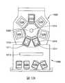
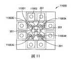
圖11例示一處理工具11000,其具有一中央轉送室11001及一或多個被可連通地耦合至該中央轉送室11001的一或多個側邊的處理模組11002(其實質地類似上文中所描述者)。該中央轉送室11001可具有任何適合的多邊形形狀。在此態樣中,一或多個界接模組201可被整合至或以其它方式連接至該中央轉送室,以允許一或多個基材盒210耦合至該處理工具11000,使得一無塵通道被形成在該等基材盒210和該處理工具的任何適合的位置之間。一或多個機器人運送器11003A-11003D可被設置在該中央轉送室11001內,譬如設置在該中央轉送室的每一角落處,用來將基材運送於彼此之間、該處理模組11002和該等界接模組201之間。可被瞭解的是,雖然有兩個處理模組11002被顯示在該中央轉送室11001的每一側上,但在其它態樣中,任何適當數量的處理模組都可以並排組態及/或堆疊組態被耦合至該處理模組的每一側。在一態樣中,一頭頂式運送器(未示出)或任何其它適合的運送器可將基材盒210運送至該處理工具11000的界接模組201。可被瞭解的是,該中央轉送室亦可包括任何其它適合的處理設備,譬如基材對準器及基材暫存器。FIG. 11 illustrates a
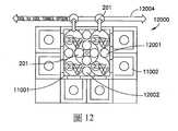
圖12例示一和處理工具11000實質地相類似之處理工具12000。在此態樣中,該中央轉送室11001被顯示為具有基材對準器12001及基材暫存器12002,其被設置在該中央轉送室11001內。一運送器12004(譬如,一頭頂式運送器或其它適合的運送器)被顯示為和該中央轉送室11001的一側以任何適合的方式相界接。在一態樣中,一或多個界接模組201可提供介於該運送器12004和該中央轉送室11001之間的界接,而在其它的態樣中,任何其它適合的界接(譬如,一包括一或多個裝載埠的設備前端模組)可被提供來作為該運送器12004和該中央轉送室11001之間的界接。FIG. 12 illustrates a
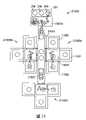
現參考圖13,依據被揭露的實施例的態樣的另一示範性處理工具13000被示出。該中央轉送室13001包含一或多個不同的轉送室13001A-13001D,它們係以任何適合方式彼此連接,使得一無塵通道被形成在該等轉送室13001A-13001D之間。該等不同的轉送室的每一者可包括一或多個基材運送機器人13003且藉由界接模組201彼此連接、及/或任何適合的負載鎖定室及/或暫存器模組13005。可被瞭解的是,雖然該等界接模組201被顯示為沿著該中央轉送室13001的中心線被設置成直線,但在其它態樣中,該等界接模組201及/或負載鎖定室及/或暫存器模組13005可具有任何適合的組態。Referring now to FIG. 13, another
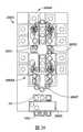
圖14例示一實質類似於處理工具13000的處理工具14000,但在此態樣中,該等界接模組201被集中式地以叢集式配置的方式設置在該中央轉送室14001中,使得每一不同的轉送室13001A-13001D係藉由一界接模組201和一負載鎖定室或暫存器模組13005這兩者而連接至另一不同的轉送室13001A-13001D。可被瞭解的是,該等基材盒210可用任何適合的方式(譬如,那些描述於本文中的方式)被運送至該等處理工具13000,14000。14 illustrates a
圖15例示一處理工具15000,其具有一中央界接模組,其具有兩個用來固持兩個基材盒210的埠板209。如上文中提到的,該中央界接模組可以是多埠界接模組,其具有一用於該等埠板209的共同內艙室或用於每一埠板209之分離的內艙室。在此態樣中,轉送室15001A,15001B(其實質類似於上文中所描述的轉送室)被連接至該界接模組201的相反側上。每一轉送室15001A,15001B可具有一或多個用任何適合的方式(譬如,描述於本文中的方式)連接至該轉送室15001A,15001B的一側或多側的處理室11002。處理工具可具有端部15000E1,15000E2,無塵通道係延伸在該等端部15000E1和15000E2之間。該界接模組可被設置在該無塵通道的兩端之間且可界定該無塵通道的一中間入口或一中途入口,用來將基材插入該無塵通道中或將基材從該無塵通道取出。FIG. 15 illustrates a
圖16例示一具有叢集式架構的處理工具16000。該處理工具16000包括一多面的中央式轉送室16001,其具有一或多個連接至轉送室16001的一或多個面及/或側的處理模組。在此態樣中,兩個界接模組201被連接至該轉送室16001的各個面,而在其它態樣中,任何適當數量的界接模組都可被連接至該轉送室16001。一或多個適合的轉送機器人16003可被設置在該轉送室16001內,用來將基材轉送於耦合至該等界接模組201及該等處理模組11002的基材盒210之間。Figure 16 illustrates a
圖17及18例示處理工具17000,18000,它們類似於處理工具15000。然而,在這些態樣中,該界接模組包括三個埠板209,用來將三個基材盒210耦合至該等處理工具17000,18000。可被理解的是,該等轉送室17001A,17001B可以是直線式細長形的轉送室,其具有一長度,該長度相當於該界接模組201的長度。每一轉送室17001A,17001B可包括一或多個轉送機器人17002,它們(用任何適合的方式)被適當地建構來伸展於一各自的轉送室17001A,17001B的長度上,用以進出該界接模組201的每一可密封的開口201S及每一連接至該轉送室17001A,17001B的處理模組11002。應指出的是,至少一處理模組11002可用並排及/或疊置的方式被連接至轉送室17001A,17001B之和該界接模組相反的細長側。Figures 17 and 18 illustrate
圖19例示一處理工具19000,其實質類似於上文中參考圖17及18所描述的處理工具。然而,只有轉送室17001A被提供。該運送器12004被設置來將基材盒210轉送至界接模組201。可被瞭解的是,該運送器12004亦可移動於圖17及18的轉送室17001A,17001B之間,用以將基材盒210轉送至界接模組201。FIG. 19 illustrates a
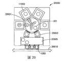
圖20例示一種叢集式處理工具20000,其具有一中央轉送室20001(其可實質地類似於轉送室16001)、一或多個連接至該轉送室20001的處理模組及一連接至該轉送室20001的設備前端模組20005。該設備前端模組20005可實質地類似於上文中所描述者(參見圖1A-1D)且可用任何適合的方式(譬如,透過一或多個負載鎖定室20003)連接至該轉送室20001。在一些實施例中(未示出),該等負載鎖定室20003的一者或兩者可用一界接模組來取代且界接模組201可從該轉送室20001被取下。可被瞭解的是,該轉送室20001可包括一界接模組201及/或一或多個處理模組11002可用界接模組201來取代。可被瞭解的是,一或多個適當的運送器20010可被供來將基材匣盒1050轉送至該設備前端模組20005及/或將基材盒210轉送至該界接模組201。Figure 20 illustrates a
現參考圖21,依據被揭露的實施例的態樣的另一處理工具21000被顯示。該處理工具21000包括一細長形的界接模組201及轉送室17001A,其實質地類似上文中參考圖17及18所描述者。一細長形的轉送室21001可被連接至該轉送室17001A並包括一或多個適當的運送台車21002(如,具有固定式基材支撐件的被動式台車或具有一或多個安裝在台車上的運送手臂的主動式台車),其被建構來橫越該細長形的轉送室21001的長度。該等運送台車21002可用任何適合的方式(譬如,藉由磁浮、纜繩、皮帶或任何其它組態)沿著該細長形的轉送室21001的長度被驅動。該等運送台車21002亦可被建構來從彼此的上方/底下通過並可包括Z字形運動能力,用來將基材沿著不同的轉送平面轉送及轉送至具有疊置式入口及出口的處理模組及/或轉送室。一或多個處理單元21005A-21005C可用任何適合的方式被實質地連接至該細長形的轉送室21001(如,透過一可密封的埠口)並沿著該細長形的轉送室21001的任何部分。在一態樣中,每一處理單元可包括一中央轉送室15001及一或多個連接至該中央轉送室15001的處理模組11002。在其它態樣中,該等處理單元可例如藉由一負載鎖定室或暫存器模組而被連接至該細長形的轉送室21001。處理單元21005C被設置在該細長形的轉送室21001的一和該界接模組201相反的端部且處理單元21005A,21005B被設置在該細長形的轉送室21001的相對的側壁上。在其它態樣中,該細長形的轉送室21001可具有任何適合的長度,使得任何適合數量的處理單元可被連接至該細長形的轉送室21001。亦可被瞭解的是,該界接模組201和該轉送室17001A可被設置在沿著該細長形的轉送室21001的任何適合的位置。在一態樣中,多於一個的界接模組201(及相關連的轉送室)可被連接至該細長形的轉送室21001及/或被包含在該等處理單元21005A-21005C的一者或多者中。Referring now to FIG. 21, another
現參考圖22及23,依據被揭露的實施例的態樣的另一處理工具22000被例示。該處理工具22000可實質地類似於處理工具21000。但是,在此態樣中,該界接模組可以是細長形的,用以和任何適當數量的基材盒210相界接(在圖22中該界接模組201為了示範的目的而被例示為被建構來和六個基材盒界接,在圖23中該界接模組201為了示範的目的而被例示為被建構來和四個基材盒界接)。可被瞭解的是,將該界接模組201連接至該細長形的轉送室21001的該轉送室22001亦可以是細長形且被建構來接近(access)該界接模組201的每一密封的開口201S。例如,該轉送室22001可包括兩個固定不動的轉送機器人17002,其實質地類似於上文中參考圖17及18所描述的轉送機器人。每一轉送機器人17002可被建構來將基材運送於該界接模組201和該細長形的轉送室21001之間。在其它態樣中,該轉送室22001可包括一或多個安裝在一梭車(shuttle)或滑車上的轉送機器人,使得該等轉送機器人可用一類似於上文中關於台車21002所描述的方式橫越該轉送室22001的長度。Referring now to FIGS. 22 and 23, another
參考圖24,另一處理工具24000被例示。在此態樣中,該處理工具包括兩個界接模組201A,201B及相關連的轉送室、一第一細長形的轉送室區21001A、一第二細長形的轉送室區21001B、一或多個處理單元21005A-21005C及一內嵌式(inline)轉送室17001C。每一轉送室17001A-17001C可包括一或多個運送機器人17002,其實質類似於上文中所描述的運送機器人。每一細長形的轉送室區21001A,21001B可包括一或多個台車21002,其實質地類似於上文所描述的台車。轉送室17001A,17001B可被連接至該第一細長形的轉送室區21001A的相反側邊,用來將基材轉送於耦合至該界接模組201A,201B的基材盒210之間並進入該第一細長形的轉送室區21001A內。該內嵌式轉送室17001C可用任何適合的方式將該第一細長形的轉送室區21001A和該第二細長形的轉送室區21001B相連接。該內嵌式轉送室17001C的縱長軸線和該第一及第二細長形的轉送室區21001A,21001B的縱長軸線對齊。處理單元21005A,21005C可用任何適合的方式(譬如,藉由一或多個負載鎖定室24001-24004)而被連接至該內嵌式轉送室17001C。應指出的是,每一負載鎖定室24001-24004可包括一或多個堆疊式的負載鎖定室,用來沿著不同的堆疊式運送平面將基材轉送於各處理單元21005A,21005C和該內嵌式轉送室17001C之間。處理單元21005B可用任何適合的方式被設置在該第二細長形的轉送室區21001B的一端且亦可包括堆疊式基材轉送/處理平面。可被瞭解的是,在其它態樣中,該處理工具24000的構件可具有任何適合的配置來處理基材。Referring to FIG. 24, another
參考圖25,依據被揭露的實施例的態樣的另一處理工具25000被例示。該處理工具25000可實質地類似於處理工具21000,22000,23000及24000。但是,可被瞭解的是,描述於本文中的該等處理工具的任何一者可例如用任何適何的方式被連接至該細長形的轉送室21001。為了舉例的目的,圖25例示處理工具12000被連接至該細長形的轉送室21001的相反的側邊。Referring to FIG. 25, another
現參考圖26,依據被揭露的實施例的態樣的另一處理工具26000被例示。兩個處理單元18000A,18000B(每一處理單元可實質地類似於處理單元18000(圖18)或任何其它適合的處理工具,譬如描述於本文中的處理工具)可例如透過負載鎖定室26001,26002用任何適合的方式彼此連接。一設備前端模組26005(其類似於上文中所描述者)可被提供且和處理單元18000A,18000B分隔開。該設備前端模組26005可在一或多個側邊具有載入埠,用來將匣盒1050耦合至該設備前端模組26005。該設備前端模組26005亦可具有一或多個界接模組201,其被連接至該設備前端模組26005的另一側邊。該設備前端模組26005的一或多個運送機器人可將基材轉送於該等匣盒1050和耦合至每一界接模組201的基材盒210之間。該等基材盒210可用任何適合的方式(譬如,藉由運送系統26007)被轉送於連接至該設備前端模組26005的界接模組201和處理單元18000A,18000B之間。運送系統26007可以是任何運送系統,其包括但不侷限於頭頂式運送系統。在一些實施例中,該運送系統26007可將基材盒運送至位在處理單元18000A,18000B或負載鎖定室26001,26002的一者或多者的界接模組201處。在一些實施例中(未示出),負載鎖定室26001,26002的一者或兩者可被一界接模組取代。Referring now to FIG. 26, according to the aspect of the disclosed embodimentAnother
圖27例示依據被揭露的實施例的態樣的另一處理工具27000。該處理工具27000類似於處理工具26000,但在此態樣中,界接模組201A-210C的一者或多者可將該設備前端模組26005連接至處理單元18000A,18000B的一者或多者。例如,界接模組201A,201C可以是穿通式(pass through)模組,其允許基材實質地直接轉送於處理單元18000B的轉送室和該設備前端模組26005之間。界接模組201A,201C亦可以介於基材匣盒1050和基材盒210之間的基材轉送,使得基材盒可被轉送系統26007轉送至該處理工具27000的各處。FIG. 27 illustrates another
圖28及29例示處理工具28000,29000,其包括描述於本文中的處理工具的組合。例如,處理工具28000包括一用來如上文所述地將基材轉送至一或多個基材盒210的設備前端模組26005。任何適合的運送系統(譬如,運送系統26007)可將基材盒運送於該設備前端模組26005的界接模組和一或多個處理單元的界接模組之間,該處理模組在此例子中包括實質類似於處理工具19000及14000的處理單元。處理工具29000亦可包括一用來如上文所述地將基材轉送至一或多個基材盒210的設備前端模組26005。任何適合的的運送系統(譬如,運送系統26007)可將基材盒210運送於該設備前端模組26005的界接模組201和一或多個處理單元的界接模組之間,該處理模組在此例子中包括實質類似於處理工具14000的處理單元。可被理解的是,該運送系統26007可將基材盒210運送至任何適當數量及類型的處理單元。Figures 28 and 29 illustrate
圖30例示該設備前端模組26005。如上文中描述的,該設備前端模組26005可將基材轉送於基材匣盒1050和基材盒210之間。在一態樣中,該設備前端模組26005可被建構來實質直接地在基材匣盒1050和基材盒210之間(用任何適合的方式)將該等基材分類。該設備前端模組26005可被設置在一地板上或例如懸掛於天花板上或例如被支撐在橋塔(pylon)上。任何適合的運送系統(譬如,運送系統26007)可將固持該等經過分類的基材的基材盒210運送至任何適合的處理單元30000(譬如,描述於本文中的處理單元)的界接模組201。FIG. 30 illustrates the device front-
現參考圖31,一依據被描述的實施例的態樣的處理工具31000被例示。該處理工具31000可實質地類似於描述於本文中的處理工具。在一態樣中,該處理工具31000包括一大氣壓的迷你環境(EFEM)1060,其具有一或多個載入埠模組1005。一或多個負載鎖定室203可用任何適合的方式(譬如,透過一可密封的開口203S)被耦合至該迷你環境1060。一或多個界接模組201可用任何適合的方式(譬如,透過一可密封的開口203S)被耦合至該負載鎖定室203。一轉送室202可用任何適合的方式(譬如,透過一可密封的開口203S)被耦合至該負載鎖定室203及一或多個處理模組1030可被耦合至該轉送室202。在此態樣中,該等基材可經由該等界接模組201、該迷你環境1060及/或轉送室202進入或離開該負載鎖定室。該轉送室202及該等處理模組1030可形成一真空及/或大氣壓處理平台32001(參見圖32),用來在真空或大氣環境中處理基材。在一態樣中,該負載鎖定室203可包括任何適合的基材運送器,其可實質地類似於描述於上文中用來將基材轉送來回於該等真空界接裝置(如,界接模組201及轉送室202)的基材運送器。在此態樣中,該轉送室202的基材運送器202T及該迷你環境的基材運送器可將基材實質地直接地運送至該負載鎖定室203的基材運送器上,用來將基材運送通過該負載鎖定室203。在此態樣中,基材從基材盒210經由各自的界接模組201運送至該負載鎖定室203可在真空條件下(即,在該等界接模組提供一真空對真空界接的真空環境中)被實施,而在其它態樣中,該等界接模組201可提供一真空對大氣壓的界接。Referring now to FIG. 31, a
現參考圖32,一依據被描述的實施例的態樣的處理工具32000被例示。該處理工具32000可實質地類似於處理工具31000,然而,在此態樣中該等界接模組201係和該大氣壓的迷你環境1060相界接,使得基材係經由該迷你環境1060或轉送室202進出該負載鎖定室203。基材可經由該迷你環境1060進入及/或離開該等真空的界接模組201。在此態樣中,該界接模組可被建構來將一和該界接模組201相耦合的基材盒或基材載具210用描述於本文中的方式排空,使得基材可在大氣壓環境中從基材盒210被轉送至該迷你環境及使得該大氣壓環境延伸至該界接模組201的內部環境(譬如,描述於下文中的內部環境或該外殼210H的內部)。該界接模組201亦可被建構來在該基材盒210和該界接模組201脫開之前如上文所述地將該基材盒210的內部抽空降壓至真空壓力,使得該基材盒210被移動至另一處理工具或處理站。將該基材盒210的內部抽空降壓至真空壓力可提供用於下游真空處理工具或平台之批次負載鎖定室的功能。例如,該等基材可在真空的條件下抵達下游的處理工具,真空條件可在從該基材盒210轉送出基材時省掉該負載鎖定室203(如,該負載鎖定室係耦合至一其上耦合了該基材盒的界接模組)的排空及抽吸,藉以縮短該等下游真空處理工具的循環時間。圖33及34例示一處理工具的一些部分並顯示一迷你環境,其具有一或多個界接模組201,該等界接模組係在相對於該等載入埠1005和負載鎖定室203不同的位置耦合至該迷你環境。例如,圖33例示出該等載入埠1005和負載鎖定室203被設置在該迷你環境1060的縱長向側面上,而一或多個界接模組201則是被設置在該迷你環境1060的側邊的一者或多者上。圖34例示出一負載鎖定室203及一界接模組201被設置在該迷你環境1060的同一縱長向側面上。在其它態樣中,該等界接模組、載入埠模組及負載鎖定室可相對於彼此及該迷你環境1060具有任何適合的配置。Referring now to FIG. 32, a
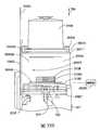
圖35A及35B例示一依據被描述的實施例的態樣的處理工具(其實質地類似於上文所描述的處理工具)的一些部分,其中該界接模組201’可包括一莢盒(如,基材載具)對工具的界面,其被建構來將一下開口型基材盒210選擇性地和一具有用於側開式莢盒的盒子打開器/載入器對工具標準(box opener/loader to tool standard;BOLTS)界面35001之迷你環境1060、負載鎖定室203及/或轉送室202相界接。在一態樣中,該界接模組201’包括一框架201F,其具有至少一可關閉的開口201FO,基材可通過該開口且該口被建構來耦合至該迷你環境1060(如,大氣壓處理室)及真空處理室(譬如,該負載鎖定室203(參見圖31))的一者或多者。在一態樣中,一門界面209D’及升降器730(其可實質類似於描述於上文中的埠門209D及升降器730)可被連接至該框架201F。該升降器730可將該門界面209D’在箭頭799所示的方向上移動一適當的量,使得例如在該架子210R中的基材和與該界接模組201’相連接的該迷你環境1060及/或負載鎖定室203的一基材運送器的運送平面對準。在該迷你環境1060及/或負載鎖定室203的一基材運送機器人包括一用來將該機器手臂移動於箭頭799的方向上的Z軸驅動器的態樣中,該升降器730可具有一用來實施該盒門210D和該盒外殼210H的分離的減小的行程。在該迷你環境1060及/或負載鎖定室203的一基材運送機器人沒有包括一用來將該機器手臂移動於箭頭799的方向上的Z軸驅動器的其它態樣中,該升降器730可具有任何適合的行程來實施該盒門210D和該盒外殼210H的分離並標示該基材盒210的基材架子210R並沿著該機器手臂的一轉送平面放置該基材盒210所攜載的每一片基材。35A and 35B illustrate some parts of a processing tool according to the aspect of the described embodiment (in fact, the texture is similar to the processing tool described above), wherein the interface module 201' may include a pod (such as , The substrate carrier) to the tool interface, which is constructed to selectively open the bottom opening
該界接模組201’亦可包括一環境護罩35002,其在一態樣中可移動於箭頭799的方向上。該護罩(shroud)35002可用任何適合的方式且被任何適合的驅動器驅動於箭頭799的方向上的一縮回的位置35030和一伸展的位置35031之間。例如,驅動器35005(其可實質地類似於升降器730及/或實質地類似於描述在1998年8月4日頒發的美國專利第5,788,458號及2000年7月4日頒發的美國專利第6,082,949號中的驅動器,這些專利的揭露內容藉此參照而被併於本文中)可被連接至該護罩35002,用以將該護罩35002移動於箭頭799的方向上的該縮回的位置35030和該伸展的位置35031之間。該驅動器35005可以是一線性致動器、螺旋驅動器或用來如本文所述地移動該護罩35002之任何其它適合的驅動器。該護罩35002可包括一盒外殼界面35010及一或多個側壁35011。該盒外殼界面35010可包括任何適合的埠密封件500,用來將該盒外殼210H密封至該盒外殼界面35010。該盒外殼界面35010亦可包括一或多個夾鉗35590,其被建構來將該盒外殼210H夾持於該盒外殼界面35010上。在一態樣中,該密封件590及該一或多個夾鉗35590可實質地類似於上文中例如參考圖5A-10所描述的密封件及夾鉗。可被瞭解的是,該盒外殼界面35010可包括一孔洞,其圍繞該門界面209D’,使得在該盒外殼界面35010透過該密封件590及夾鉗35590和該盒外殼210H相耦合的同時,該盒門210D和該門界面209D’相界接。該盒外殼界面35010可用任何適合的方式耦合至該一或多個側壁35011並形成一密封。該一或多個側壁35011可密封該載入埠1040,使得當該盒外殼210H耦合至該盒外殼界面35010時,該盒外殼界面35010和該一或多個側壁35011形成一被密封的或被隔離的受控制的環境的圍體(enclosure)35002E。The interface module 201’ can also include an
在一態樣中,任何適合的密封件都可被設置在該一或多個側壁35002和該載入埠1040之間及該盒外殼界面35010和該載入埠1040之間,用以密封該護罩35002和該載入埠1040密封。例如,當該護罩35002被移動於箭頭799的方向上以形成該被隔離的受控制的環境的圍體35002E時,該等側壁35011可用任何適合的方式和載入埠1040的BOLTS界面35001的密封件35020A,35020B界接。在一態樣中,該等密封件35020A,35020B可被設置在該BOLTS界面35001上(或該載入埠1040的任何其它適合的位置上)及/或該等側壁35011上。該等密封件35020A,35020B可以是任何適合的密封件,譬如曲徑密封件(labyrinth seal)、伸縮套密封件(bellow seal)或被建構來保持一被控制的或被隔離的真空及/或氣氛環境35002E於該護罩35002和該載入埠1040之間之任何其它密封件。該盒外殼界面35010可被建構來用任何適合的方式和該載入埠1040的BOLTS界面35001的密封件35020C界接。該密封件35020C可延伸在密封件35020A,35020B之間。在一態樣中,該等密封件35020A,35020B,35020C可以是整體的一件式結構,而在其它態樣中,該等密封件35020A,35020B,35020C的一或多者可以是和其它密封件相界接之個別的密封件。應指出的是,該護罩35002的底部35002B可和該界接模組201’形成任何適合的密封,使得它在和該等密封件35020A,35020B,35020C相結合時可形成該介於該護罩35002和該載入埠1040之間的該被隔離的被控制的環境的圍體35002E。介於該護罩35002的底部和該介面模組201’之間的密封件可以是任何適當的密封件,譬如風箱軟管式密封件、壓縮密封件、曲徑式密封件或任何其它適合的密封件。在一態樣中,該密封件35020A,35020B可被設置在BOLTS界面35001上(或該載入埠1040的任何其它適合的位置上)及/或在該等側壁35011上。該等密封件35020A,35020B可以是任何適當的密封件,譬如伸縮套密封件、壓縮密封件、曲徑式密封件或被建構來保持一被控制的或被隔離的真空及/或氣氛環境於該護罩35002和該載入埠1040之間之任何其它適合的密封件。In one aspect, any suitable seal can be provided between the one or
在該界接模組201’的操作中,任何適合的基材盒210運送器(譬如,任何適合的頭頂式運送系統、手動式操作器等等)可將一基材盒210運送至該界接模組201’(圖36,方塊36000)。應被瞭解的是,雖然該界接模組201’的操作在本中係參考該迷你環境1060來描述,但在其它態樣中,該界接模組201’和該負載鎖定室203及轉送室202的一者或多者之間的互動可實質地類似於本文中關於迷你環境1060所描述的互動。該基材盒210可和該界接模組201’對接(圖36,方塊36001),使得例如該盒門210D和該門界面209D’用任何適合的方式(譬如,用描述於本文中的方式)相匹配,及使得該盒外殼210H和該護罩35002的盒外殼界面35010形成一密封。在一態樣中,該基材盒210可在對接位置時被運送至該界接模組201’,而在其它態樣中,該基材盒210可在未對接的位置時被運送至界接模組201’。當該基材盒是在未對接的位置被運送時,該界接模組201’可包括任何適合的梭車(shuttle)或運送單元,用來將該基材盒210從該未對接的位置移動至對接的位置。該門界面209D’可實質類似於描述於上文中的埠門209D。介於該門界面209D’和盒門210D之間的任何空間可排空(在此態樣中,其被抽空至真空及/或被通風),用以例如去除污染物(圖36,方塊36002)。該盒門210D可用上文中所描述的方式從該盒外殼210H鬆脫開且該驅動器730可移動該盒門210D以及置於其上的基材堆,用以將該盒門210D與該盒外殼210H分開並將該基材堆中的一預定的基材置於一預定的位置/高度35040。During the operation of the interface module 201', any
該基材盒210的內部體積及/或介於該盒門210D和該門界面209D’之間的空間可用任何適合的氣體(如,氮氣或其它鈍氣)將其排空(如,在此態樣中為沖洗),使得在該基材盒210的內部體積中及/或介於該盒門和該門界面之間的空間中的壓力是大氣壓力,其實質等於或大於該迷你環境1060內的壓力(圖36,方塊36003)。在一態樣中,該基材盒210可在真空條件下(如,該基材盒的內部體積被保持在真空壓力)被送至該界接模組201’並用上文中描述的方式被升高至大氣壓力,用以和該迷你環境1060相界接。在其它態樣中,該基材盒210可在大氣壓條件下(如,被送至該基材盒的內部體積被保持在大氣壓力)被送至該界接模組201’並用上文中描述的方式用鈍氣加以沖洗,用以和該迷你環境1060相界接。在該界接模組被耦接至該被建構來維持真空的室(譬如,該負載鎖定室203及該轉送室202)的另外其它的態樣中,該基材盒210內的真空可被’該界接模組201’維持,使得該負載鎖定室203及/或該轉送室202的真空環境和該基材盒210及/或該被隔離的受控制的環境圍體35002E共享。The internal volume of the
該驅動器35005可將該護罩35002移動於箭頭799的方向上,使得該盒外殼210H如圖35B所示地被移離開該盒門210D,使得在該架子210R上的基材堆被外露或可被該迷你環境的任何適合的基材運送器存取(圖36,方塊36004)。在一態樣中,該盒外殼210H可被該護罩35002用類似於描述在1998年8月4日頒發的美國專利第5,788,458號及2000年7月4日頒發的美國專利第6,082,949號中的方式抬高,這些專利的揭露內容藉此參照而被併於本文中。在其它態樣中,該護罩35002可以是實質固定不動且被設置來將該被隔離的受控制的環境圍體35002E提供在載入埠1040周圍。該基材盒210可被送置該實質固定不動的護罩35002的盒外殼界面35010(其中,在該盒外殼界面上的孔洞被該埠板209’用實質類似於上文中參考界接模組201所描述的方式密封)。應指出的是,該驅動器730可包括任何適合的行程,使得在該架子210R內的基材堆可從該實質固定不動的護罩35002的盒外殼界面35010被降低,用以沿著該迷你環境的一轉送平面用一類似於下文中所描述的方式放置一預定的基材或基材支撐件210RS。The
該載入埠門1040D可用任何適合的方式打開,使得至少部分地由該護罩35002形成的該被隔離的受控制的環境圍體的內部和該迷你環境1060的內部係透過開口201FO相連通(圖36,方塊36005)。該驅動器730可將該架子210R移動於箭頭799的方向上,使得一預定的基材(或基材固持支撐件210RS)被基材運送器(其可以實質類似於描述於上文中的運送機器人1013)沿著該迷你環境1060的一轉送平面被放置,用以將該預定的基材轉送至該迷你環境1060及/或從該迷你環境1060送出(圖36,方塊36006)。在其它態樣中,該迷你環境的基材運送器可包括Z軸驅動器,使得該迷你環境的一轉送平面可移動於箭頭799的方向上,用來在該架子210R保持固定不動的同時,在箭頭799的方向上將基材從該架子210R取出或將基材放置到該架子210R內。The loading
可被瞭解的是,將基材盒210從該界接模組201’運送出來可用和參考圖36所描述的方式實質相反的方式來實施。在一態樣中,該界接模組201’可包括一或多個真空幫浦及/或粗抽閥(譬如描述於上文中者),其被建構來在該基材盒210從該界接模組201’被移出之前將該基材盒210的內部體積抽吸至任何適合的真空壓力。It can be understood that transporting the
可被瞭解的是,雖然一或多個界接模組201’被例示為在該迷你環境的一共同側邊上,但在其它態樣中,該界接模組201’可被設置在該迷你環境(如上文中所述者)的任何適合的側邊上,譬如BOLTS界面35001或該迷你環境1060的任何其它適合的界面。亦可被瞭解的是,該界接模組201’可提供真空對大氣的界面、大氣對真空的界面的一者或多者,或者兩者,其係例如依上游及下游基材處理流程需求而定。例如,在一態樣中,一或多個界接模組201’可被設置在一製造工廠37000內,如圖37所示。該製造工廠可實質類似於描述在2012年9月25日頒發的美國專利第8,272,827號中的製造工廠,該專利的內容藉此參照而被併於本文中。在一態樣中,該製造工廠包括處理模組PTC,PTC1,PTC2,PTB1,PTB2,PTA1,PTA2及任何適合的運送器37001,用來將基材盒210運送至該等界接模組201’或由該等界接模組201’運送出來。可被瞭解的是,這些處理模組PTC,PTC1,PTC2,PTB1,PTB2,PTA1,PTA2中的一些處理模組可以是大氣壓式處理模組,而這些處理模組PTC,PTC1,PTC2,PTB1,PTB2,PTA1,PTA2的其它處理模組可以是真空式處理模組。在此態樣中,該運送器37001是一頭頂式運送系統,其包括頭等式基材盒儲槽37001S,但在其它態樣中,該運送器37001可以是任何適合的運送器。在一態樣中,界接模組201’可被連接至一位在介於大氣壓式處理站PTC和真空處理PTC2之間的處理流程上的大氣壓式處理站PTC1(譬如,在一EFEM或其它大氣壓室)。在處理站PTC1處的該界接模組201’可被建構來將該基材盒210界接至該大氣壓式處理,然後將該基材盒210抽空至一真空,用來和處理模組PCT2的真空處理相界接(如,一負載鎖定操作可被省略掉,因為該基材盒210已經是在真空氣氛中,使得該基材盒210可用實質類似於2008年5月19日提申之名稱為“Side Opening Unified Pod”的美國專利申請案第12/123,391號中所描述的方式實質直接地和真空環境相界接)。在處理站PTC2處的該界接模組201’可以是在大氣壓式處理站PTB1的上游,使得該基材盒210可在其內部是在真空氣氛的情形下被送至處理站PTB1,該處理站PTB1的界接模組201’將基材盒210排空,用以和處理站PTB1的大氣環境界接。在其它態樣中,在處理站PTC2處的該界接模組可將基材盒210排空,使得該基材盒210的內部是在大氣壓力下,用來輸送至該大氣壓式處理站PTB1。It can be understood that although one or more interface modules 201' are illustrated as being on a common side of the mini-environment, in other aspects, the interface module 201' can be placed on the On any suitable side of the mini environment (as described above), such as the BOLTS interface 35001 or any other suitable interface of the
依據被揭露的實施例的一或多個態樣,一種基材運送系統包括一載具,其具有一形成一內部環境的外殼,其具有一用來固持至少一個基材的開口及一用來將該開口和一外部氣氛密封隔開的門,當該開口被密封時,該內部環境被建構來在其內維持一內部氣氛,該外殼包括一在該內部環境外面且被建構來容納一流體的流體儲槽,其在該流體儲槽內形成一不同於該內部氣氛的氣氛,用以形成一流體阻隔密封件,其將該內部環境和一在該載具外面的環境密封地隔開。According to one or more aspects of the disclosed embodiments, a substrate transport system includes a carrier having an outer shell forming an internal environment, an opening for holding at least one substrate, and an opening for holding at least one substrate. A door that seals the opening from an external atmosphere. When the opening is sealed, theThe internal environment is constructed to maintain an internal atmosphere therein, and the housing includes a fluid storage tank outside the internal environment and constructed to contain a fluid, which forms an atmosphere different from the internal atmosphere in the fluid storage tank , Used to form a fluid barrier seal, which seals the internal environment from an environment outside the carrier.
依據被揭露的實施例的一或多個態樣,該流體儲槽被建構來在該第一環境的一缺口處將流體釋入到該內部環境中。According to one or more aspects of the disclosed embodiments, the fluid storage tank is configured to release fluid into the internal environment at a gap in the first environment.
依據被揭露的實施例的一或多個態樣,該基材運送系統包括一真空室,其具有一載具界面,該載具界面被建構來支撐該載具以用於該真空室內的至少一基材的運送。According to one or more aspects of the disclosed embodiments, the substrate transport system includes a vacuum chamber having a carrier interface configured to support the carrier for use in at least the vacuum chamber The transportation of a substrate.
依據被揭露的實施例的一或多個態樣,該外殼和該門的至少一者包括一冗餘的密封配置,該冗餘的密封配置包括至少一真空密封件,其被設置在該開口的周邊周圍及至少一流體儲槽密封件。According to one or more aspects of the disclosed embodiment, at least one of the housing and the door includes a redundant sealing configuration, and the redundant sealing configuration includes at least one vacuum seal disposed at the opening And at least one fluid storage tank seal around the periphery of the device.
依據被揭露的實施例的一或多個態樣,該流體儲槽容納一氣體,其在一大於該內部氣氛的壓力的壓力。According to one or more aspects of the disclosed embodiments, the fluid storage tank contains a gas at a pressure greater than the pressure of the internal atmosphere.
依據被揭露的實施例的一或多個態樣,該流體儲槽容納一氣體,其在一大於大氣壓力的壓力。According to one or more aspects of the disclosed embodiments, the fluid storage tank contains a gas at a pressure greater than atmospheric pressure.
依據被揭露的實施例的一或多個態樣,該內部氣氛是在一小於大氣壓力的壓力。According to one or more aspects of the disclosed embodiments, the internal atmosphere is at a pressure less than atmospheric pressure.
依據被揭露的實施例的一或多個態樣,該載具的外殼被建構來支持一真空內部環境。According to one or more aspects of the disclosed embodiment, the loadThe enclosure of the tool is constructed to support a vacuum internal environment.
依據被揭露的實施例的一或多個態樣,該冗餘的密封配置的至少一真空密封件包括一設置在一第一平面的第一密封件及一設置在一第二平面的第二密封件,該第一及第二平面彼此不同。According to one or more aspects of the disclosed embodiments, the at least one vacuum sealing element of the redundant sealing configuration includes a first sealing element arranged on a first plane and a second sealing element arranged on a second plane. For the seal, the first and second planes are different from each other.
依據被揭露的實施例的一或多個態樣,該冗餘的密封配置的該等密封件的每一者和在該外殼及門的至少一者上的下凹式密封表面相匹配。According to one or more aspects of the disclosed embodiments, each of the seals of the redundant sealing arrangement matches the concave sealing surface on at least one of the housing and the door.
依據被揭露的實施例的一或多個態樣,該外殼包括一和該流體儲槽連通的流體儲槽通道,使得該流體阻隔密封件被設置在該至少一真空密封件的外面且至少一流體儲槽密封件被設置在該流體儲槽通道的周邊的周圍。According to one or more aspects of the disclosed embodiments, the housing includes a fluid storage tank channel communicating with the fluid storage tank, so that the fluid barrier seal is disposed outside the at least one vacuum seal and at least one The fluid storage tank seal is arranged around the periphery of the fluid storage tank channel.
依據被揭露的實施例的一或多個態樣,該流體儲槽被建構來在該至少一真空密封件的缺口處將流體經由該流體儲槽通道釋出到該內部環境中。According to one or more aspects of the disclosed embodiments, the fluid storage tank is configured to release fluid into the internal environment through the fluid storage tank channel at the gap of the at least one vacuum seal.
依據被揭露的實施例的一或多個態樣,該門被該內部環境的真空力密封至該外殼。According to one or more aspects of the disclosed embodiments, the door is sealed to the housing by the vacuum force of the internal environment.
依據被揭露的實施例的一或多個態樣,該門係透過該內部環境和該真空室之間的動態壓力平衡而被釋開。According to one or more aspects of the disclosed embodiments, the door is released through the dynamic pressure balance between the internal environment and the vacuum chamber.
依據被揭露的實施例的一或多個態樣,該載具界面包括一冗餘的密封配置,其包括一設置在一第一平面的第一密封件及一設置在一第二平面的第二密封件,該第一及第二平面係彼此實質地正交。According to one or more aspects of the disclosed embodiments, the carrier interface includes a redundant sealing configuration, which includes a first sealing element arranged on a first plane and a second sealing element arranged on a second plane. For the two seals, the first and second planes are substantially orthogonal to each other.
依據被揭露的實施例的一或多個態樣,該基材運送器包括一被動式門鎖,其被建構來在該真空力喪失時將該門維持在該外殼上。According to one or more aspects of the disclosed embodiments, the substrate transporter includes a passive door lock configured to maintain the door on the housing when the vacuum force is lost.
依據被揭露的實施例的一或多個態樣,該被動式門鎖包含一球鎖凹陷部及一球鎖柱塞。According to one or more aspects of the disclosed embodiments, the passive door lock includes a ball lock recess and a ball lock plunger.
依據被揭露的實施例的一或多個態樣,該基材運送系統包括一將該門維持在該外殼的被動式門鎖,而該載具界面係被建構來釋開該被動式門鎖。According to one or more aspects of the disclosed embodiments, the substrate transport system includes a passive door lock that maintains the door in the housing, and the carrier interface is configured to release the passive door lock.
依據被揭露的實施例的一或多個態樣,該真空室包括至少一可密封的開口,用來將該真空室耦接到至少一基材處理模組。According to one or more aspects of the disclosed embodiments, the vacuum chamber includes at least one sealable opening for coupling the vacuum chamber to at least one substrate processing module.
依據被揭露的實施例的一或多個態樣,該載具界面包括一清洗埠,其被建構來清洗一介於該門和該載具界面之間的空間及一介於該門和該外殼之間的密封件的至少一者。According to one or more aspects of the disclosed embodiment, the carrier interface includes a cleaning port configured to clean a space between the door and the carrier interface and a space between the door and the housing At least one of the seals between.
依據被揭露的實施例的一或多個態樣,該載具界面是一被動式界面。According to one or more aspects of the disclosed embodiments, the carrier interface is a passive interface.
依據被揭露的實施例的一或多個態樣,一種基材運送器包括一外殼,其形成一用來容納至少一基材於一第一氣氛中的內部環境,該外殼包括一通到該內部環境的開口及一形成一流體阻隔密封件的流體儲槽,其具有一不同於該第一氣氛且在該第一氣氛外的第二氣氛,一被建構來關閉該開口的門,當該開口被關閉時,該外殼被建構來維持該第一氣氛於該內部環境內,及一被設置在該外殼和該門的至少一者上之冗餘的密封配置,該冗餘的密封配置包括至少一第一密封件,其被置在該開口的周邊的周圍及至少一第二密封件,該第二密封件被設置在該第一密封件和該流體阻隔密封件之間。According to one or more aspects of the disclosed embodiments, a substrate transporter includes a housing that forms an internal environment for accommodating at least one substrate in a first atmosphere, and the housing includes a The opening of the environment and a fluid storage tank forming a fluid barrier seal, which has a second atmosphere different from the first atmosphere and outside the first atmosphere, a door constructed to close the opening, when the opening When closed, the housing is constructed to maintain the first atmosphere in the internal environment, and one is set in the housingAnd a redundant sealing arrangement on at least one of the door, the redundant sealing arrangement includes at least one first sealing element disposed around the periphery of the opening and at least one second sealing element, the second sealing element A seal is provided between the first seal and the fluid barrier seal.
依據被揭露的實施例的一或多個態樣,該外殼包括一流體儲槽通道,其和該流體儲槽連通且被設置在該第一密封件外,該基材運送器更包括一流體儲槽密封件,其被設置在該流體儲槽通道的周邊的周圍外面。According to one or more aspects of the disclosed embodiments, the housing includes a fluid storage tank channel that communicates with the fluid storage tank and is disposed outside the first seal, and the substrate transporter further includes a fluid The storage tank seal is arranged outside the periphery of the fluid storage tank channel.
依據被揭露的實施例的一或多個態樣,該流體儲槽被建構來在該第一及第二密封件的一者或多者上的一缺口處透過該流體儲槽通道將流體釋入到該內部環境中。According to one or more aspects of the disclosed embodiments, the fluid reservoir is constructed to release fluid through the fluid reservoir channel at a gap on one or more of the first and second seals. Into the internal environment.
依據被揭露的實施例的一或多個態樣,該門係被該內部環境的一真空力密封至該外殼。According to one or more aspects of the disclosed embodiments, the door is sealed to the housing by a vacuum force of the internal environment.
依據被揭露的實施例的一或多個態樣,該基材運送器包括一被動式門鎖,其被建構來在該真空力喪失時將該門維持在該外殼上。According to one or more aspects of the disclosed embodiments, the substrate transporter includes a passive door lock configured to maintain the door on the housing when the vacuum force is lost.
依據被揭露的實施例的一或多個態樣,該被動式門鎖包含一球鎖凹陷部及一球鎖柱塞。According to one or more aspects of the disclosed embodiments, the passive door lock includes a ball lock recess and a ball lock plunger.
依據被揭露的實施例的一或多個態樣,該被動式門鎖被建構成被被動地釋開。According to one or more aspects of the disclosed embodiments, the passive door lock is configured to be passively released.
依據被揭露的實施例的一或多個態樣,該門被建構來支撐該至少一基材。According to one or more aspects of the disclosed embodiments, the door is constructed to support the at least one substrate.
依據被揭露的實施例的一或多個態樣,一種基材運送器包括一具有一內部環境的外殼,該內部環境被建構來容納至少一基材於一第一氣氛中,該第一氣氛和一基材處理氣氛是一樣的,一用來密封該內部環境的門,及一介於該門和該外殼之間的流體阻隔密封件,該流體阻隔密封件具有一不同於該第一氣氛且與該第一氣氛隔離的第二氣氛,一外密封件將該流體阻隔密封件和一在該外殼外面的外部氣氛隔離及一內密封件將該流體阻隔密封件和該第一氣氛隔離,使得一空隙存在於該流體阻隔密封件和該第一氣氛之間。According to one or more aspects of the disclosed embodiment, aThe substrate transporter includes a housing with an internal environment configured to contain at least one substrate in a first atmosphere, the first atmosphere being the same as a substrate processing atmosphere, and one for sealing the substrate The door of the internal environment, and a fluid barrier seal between the door and the housing, the fluid barrier seal has a second atmosphere different from the first atmosphere and isolated from the first atmosphere, and an outer seal The fluid barrier seal is isolated from an external atmosphere outside the housing and an inner seal separates the fluid barrier seal from the first atmosphere, so that a gap exists between the fluid barrier seal and the first atmosphere between.
依據被揭露的實施例的一或多個態樣,一中介密封件被設置來將該流體阻隔密封件和該內密封件隔離。According to one or more aspects of the disclosed embodiment, an intermediate seal is provided to isolate the fluid barrier seal from the inner seal.
依據被揭露的實施例的一或多個態樣,該流體阻隔密封件包括一流體儲槽,其不同於該內部環境且被連接至該外殼及一流體通道。According to one or more aspects of the disclosed embodiments, the fluid barrier seal includes a fluid reservoir that is different from the internal environment and is connected to the housing and a fluid channel.
依據被揭露的實施例的一或多個態樣,該流體通道將該流體儲槽連接至一介於該外殼和該門之間的界面。According to one or more aspects of the disclosed embodiments, the fluid channel connects the fluid reservoir to an interface between the housing and the door.
依據被揭露的實施例的一或多個態樣,該流體阻隔密封件是一加壓式密封件,其被設置在該外氣氛和該第一氣氛之間。According to one or more aspects of the disclosed embodiments, the fluid barrier seal is a pressurized seal, which is disposed between the outer atmosphere and the first atmosphere.
依據被揭露的實施例的一或多個態樣,一種處理系統包括基材處理工具,一環境受控制的載具,其具有一內部環境及一流體阻隔密封件,其具有一不同於該內部環境的氣氛,及一環境受控制的界接模組,其被建構來將該環境受控制的載具和該基材處理工具耦合,一通路(passage)藉由該環境受控制的載具耦合至該處理工具而被形成穿過該環境受控制的界接模組以形成一無塵通道。According to one or more aspects of the disclosed embodiments, a processing system includes a substrate processing tool, an environment-controlled carrier, which has an internal environment and a fluid barrier seal, which has an internal environment that is different from the internal environment.The atmosphere of the environment, and an environment-controlled interface module, which is constructed to couple the environment-controlled carrier and the substrate processing tool, and a passage through the environment-controlled carrier The interface module is coupled to the processing tool and formed through the environment controlled interface to form a dust-free channel.
依據被揭露的實施例的一或多個態樣,一形成在該環境受控制的界接模組的一埠門和該環境受控制的載具的下表面之間的間隙可引導一乾淨的乾燥空氣橫越界於該埠門和該下表面之間的密封件。According to one or more aspects of the disclosed embodiments, a gap formed between a port door of the environment-controlled interface module and the lower surface of the environment-controlled carrier can guide a clean The dry air traverses the seal between the port door and the lower surface.
依據被揭露的實施例的一或多個態樣,該環境受控制的界接模組界定一通到該無塵通道的中途入口或中間入口。According to one or more aspects of the disclosed embodiments, the environment-controlled interface module defines a midway entrance or intermediate entrance to the dust-free passage.
依據被揭露的實施例的一或多個態樣,該環境受控制的界接模組被設置在該無塵通道的兩端之間。According to one or more aspects of the disclosed embodiments, the environment-controlled interface module is disposed between the two ends of the dust-free channel.
依據被揭露的實施例的一或多個態樣,該環境受控制的界接模組包括一可轉動的埠門,其可移動進入到該環境受控制的界接模組的一內部體積中,該埠門的轉動允許該環境受控制的載具的自動化,用以在一不同於一被要求的晶圓堆方位的方位載入該環境受控制的載具。According to one or more aspects of the disclosed embodiments, the environment-controlled interface module includes a rotatable port that can move into an internal volume of the environment-controlled interface module The rotation of the port door allows the automation of the environment-controlled carrier to load the environment-controlled carrier in an orientation different from a required wafer stack orientation.
依據被揭露的實施例的一或多個態樣,該環境受控制的界接模組包含一穿通式(pass through)負載鎖定室。According to one or more aspects of the disclosed embodiments, the environment-controlled interface module includes a pass-through load lock chamber.
依據被揭露的實施例的一或多個態樣,當該環境受控制的載具被打開時,該環境受控制的載具的一內部氣氛和該穿通式負載鎖定室的一內部氣氛連通。According to one or more aspects of the disclosed embodiments, when the environment-controlled carrier is opened, an internal atmosphere of the environment-controlled carrier communicates with an internal atmosphere of the through-type load lock chamber.
依據被揭露的實施例的一或多個態樣,該環境受控制的界接模組是一穿通式模組,其包括一具有整合式基材支撐件的埠門。According to one or more aspects of the disclosed embodiments, the environment-controlled interface module is a through-type module that includes a port with an integrated substrate support.
依據被揭露的實施例的一或多個態樣,該等整合式基材支撐件和該埠門如一單元般地一起移動。According to one or more aspects of the disclosed embodiments, the integrated substrate supports and the port door move together as a unit.
依據被揭露的實施例的一或多個態樣,該內部環境和該處理工具的一環境是一共同的環境,其延伸穿過該環境受控制的界接模組。According to one or more aspects of the disclosed embodiments, the internal environment and an environment of the processing tool are a common environment that extends through the interface module controlled by the environment.
依據被揭露的實施例的一或多個態樣,該流體阻隔密封件是一相關於該內部環境的氣氛的加壓式密封件。According to one or more aspects of the disclosed embodiments, the fluid barrier seal is a pressurized seal related to the atmosphere of the internal environment.
依據被揭露的實施例的一或多個態樣,該環境受控制的載具包括一用來維持該內部環境的外殼及一用來密封地關閉該外殼的門,該流體阻隔密封件包括一通路,其在該門被關閉時形成在一介於該外殼和該門之間的界面處。According to one or more aspects of the disclosed embodiments, the environment-controlled vehicle includes a housing for maintaining the internal environment and a door for sealingly closing the housing, and the fluid barrier seal includes a A passage is formed at an interface between the housing and the door when the door is closed.
依據被揭露的實施例的一或多個態樣,一介於該環境受控制的載具和該環境受控制的界接模組之間的界面包括一流體埠,其用於不受該內部環境的氣氛影響地注入該流體阻隔密封件的流體。According to one or more aspects of the disclosed embodiments, an interface between the environment-controlled vehicle and the environment-controlled interface module includes a fluid port that is used to be protected from the internal environment The atmosphere is affected by the fluid injected into the fluid barrier seal.
依據被揭露的實施例的一或多個態樣,一介於該環境受控制的載具和該環境受控制的界接模組之間的界面包括一流體埠,其用於不受該內部環境的氣氛影響地將一流體從該流體阻隔密封件排空。According to one or more aspects of the disclosed embodiments, an interface between the environment-controlled vehicle and the environment-controlled interface module includes a fluid port that is used to be protected from the internal environment The atmosphere affects the evacuation of a fluid from the fluid barrier seal.
依據被揭露的實施例的一或多個態樣,該流體埠被建構來在將該環境受控制的載具及該環境受控制的界接模組的一者或多者抽吸降壓至一真空氣氛之前及/或與之分離時自動地將流體從該流體阻隔密封件中排空。According to one or more aspects of the disclosed embodiments, the fluid port is configured to suck and depress one or more of the environment-controlled vehicle and the environment-controlled interface module to A vacuum atmosphere is automatically evacuated from the fluid barrier seal before and/or when it is separated from it.
依據被揭露的實施例的一或多個態樣,該基材處理工具包括一中央轉送室及被可連通地耦合至該中央轉送室的一或多個側邊的處理模組,該環境受控制的界接模組被連接至該中央轉送室。According to one or more aspects of the disclosed embodiments, the substrate processing tool includes a central transfer chamber and processing modules communicably coupled to one or more sides of the central transfer chamber, and the environment is affected by The controlled interface module is connected to the central transfer room.
依據被揭露的實施例的一或多個態樣,該中央轉送室包括至少一轉送機器人,用來將一或多片基材轉送於該環境受控制的界接模組和該等處理模組之間。According to one or more aspects of the disclosed embodiments, the central transfer room includes at least one transfer robot for transferring one or more substrates to the environment-controlled interface module and the processing modules between.
依據被揭露的實施例的一或多個態樣,該中央轉送室具有多邊形的形狀。According to one or more aspects of the disclosed embodiments, the central transfer chamber has a polygonal shape.
依據被揭露的實施例的一或多個態樣,該中央轉送室包括多個彼此耦合的轉送室。According to one or more aspects of the disclosed embodiments, the central transfer chamber includes a plurality of transfer chambers coupled with each other.
依據被揭露的實施例的一或多個態樣,該等多個轉送室至少被該環境受控制的界接模組彼此耦合。According to one or more aspects of the disclosed embodiments, the plurality of transfer chambers are coupled to each other by at least the interface module controlled by the environment.
依據被揭露的實施例的一或多個態樣,該等多個轉送室係透過一直線式運送通道而彼此耦合。According to one or more aspects of the disclosed embodiments, the multiple transfer chambers are coupled to each other through a linear conveying channel.
依據被揭露的實施例的一或多個態樣,該環境受控制的界接模組被設置在該直線式運送通道的一或多個端部。According to one or more aspects of the disclosed embodiments, the environment-controlled interface module is disposed at one or more ends of the linear conveying channel.
依據被揭露的實施例的一或多個態樣,該基材處理工具包括一自動化的搬運系統,用來將該環境受控制的載具轉送至該環境受控制的界接模組。According to one or more aspects of the disclosed embodiments, the substrate processing tool includes an automated handling system for controlling the environmentThe manufactured vehicle is forwarded to the interface module controlled by the environment.
依據被揭露的實施例的一或多個態樣,該處理工具包括一和該環境受控制的界接模組不同的設備前端單元。According to one or more aspects of the disclosed embodiments, the processing tool includes a device front-end unit different from the interface module controlled by the environment.
依據被揭露的實施例的一或多個態樣,一種密封一基材載具的方法被提供。方法包括提供一基材載具外殼,其具有一內部環境及一用來關閉該內部環境的門,在一介於該外殼和該門之間的界面處提供一流體阻隔密封件,該流體阻隔密封件延伸在該門的周邊的周圍且具有一不同於該內部環境的氣氛。According to one or more aspects of the disclosed embodiments, a method of sealing a substrate carrier is provided. The method includes providing a substrate carrier housing with an internal environment and a door for closing the internal environment, and providing a fluid barrier seal at an interface between the housing and the door, and the fluid barrier seal The piece extends around the periphery of the door and has an atmosphere different from the internal environment.
依據被揭露的實施例的一或多個態樣,該方法更包括提供一第一密封件,其位在該介於該內部環境和該流體阻隔密封件之間的界面及提供一第二密封件,其被設置在該介於該流體阻隔密封件和一在該外殼的外面的氣氛之間的界面。According to one or more aspects of the disclosed embodiment, the method further includes providing a first sealing element located at the interface between the internal environment and the fluid barrier sealing element and providing a second sealing element The element is arranged at the interface between the fluid barrier seal and an atmosphere outside the housing.
依據被揭露的實施例的一或多個態樣,該方法更包括提供一中間密封件,其被設置在該第一密封件和該流體阻隔密封件之間。According to one or more aspects of the disclosed embodiments, the method further includes providing an intermediate sealing element disposed between the first sealing element and the fluid barrier sealing element.
依據被揭露的實施例的一或多個態樣,一種基材載入器模組包括一基材載具對處理工具的界面,其具有至少一可關閉的開口,基材可通過該開口且該開口被建構來耦合至一處理工具的一真空環境及該處理工具的大氣壓環境的一者或多者。該基材載具對處理工具的界面包括一真空界面,其被建構來允許一基材載具的內部環境開口至一處理工具的真空環境,及一大氣壓界面,其被建構來允許該基材載具的該內部環境開口至該處理工具的該大氣壓環境。According to one or more aspects of the disclosed embodiments, a substrate loader module includes an interface of a substrate carrier to a processing tool, which has at least one closable opening through which the substrate can pass and The opening is configured to be coupled to one or more of a vacuum environment of a processing tool and an atmospheric pressure environment of the processing tool. The interface of the substrate carrier to the processing tool includes a vacuum interface that is constructed to allow the internal environment of a substrate carrier to openThe vacuum environment to a processing tool and the atmospheric pressure interface are constructed to allow the internal environment of the substrate carrier to open to the atmospheric pressure environment of the processing tool.
依據被揭露的實施例的一或多個態樣,該基材載具對處理工具的界面被建構來排空或充注一設置在該基材載具的一門和該基材載具的一外殼之間的基材載具流體阻隔密封件。According to one or more aspects of the disclosed embodiments, the interface of the substrate carrier to the processing tool is constructed to empty or fill a door provided on the substrate carrier and a door of the substrate carrier. The substrate carrier between the shells carries a fluid barrier seal.
依據被揭露的實施例的一或多個態樣,該基材載具對處理工具的界面被建構來排空或充注該基材載具的內部環境。According to one or more aspects of the disclosed embodiments, the interface of the substrate carrier to the processing tool is configured to drain or fill the internal environment of the substrate carrier.
依據被揭露的實施例的一或多個態樣,該基材載具對處理工具的界面包括一Z軸驅動器,用來將該基材載具的至少一部分移動於一方向上,該方向係橫貫一將基材運送進出該基材載具的轉送平面。According to one or more aspects of the disclosed embodiments, the interface of the substrate carrier to the processing tool includes a Z-axis driver for moving at least a part of the substrate carrier in one direction, the direction traversing -The substrate is transported in and out of the transfer plane of the substrate carrier.
依據被揭露的實施例的一或多個態樣,該基材載具對處理工具的界面被建構來將該基材載具的外殼和該基材載具的門分開,用以露出連接至該門的基材架。According to one or more aspects of the disclosed embodiments, the interface of the substrate carrier to the processing tool is constructed to separate the housing of the substrate carrier and the door of the substrate carrier to expose The substrate frame of the door.
依據被揭露的實施例的一或多個態樣,該基材載具對處理工具的界面被建構來耦合至一基材處理工具的一負載鎖定室。According to one or more aspects of the disclosed embodiments, the interface of the substrate carrier to the processing tool is configured to be coupled to a load lock chamber of a substrate processing tool.
依據被揭露的實施例的一或多個態樣,該基材載具對處理工具的界面被建構來耦合至一基材處理工具的一迷你環境。According to one or more aspects of the disclosed embodiments, the interface of the substrate carrier to the processing tool is constructed to be coupled to a mini environment of a substrate processing tool.
依據被揭露的實施例的一或多個態樣,一種基材處理工具包括一大氣壓處理室,其具有一大氣壓環境於其內,且被連接至該大氣壓處理室,及一基材載具對處理工具的界面,其具有至少一可關閉的開口,基材可通過該開口且該開口被建構來耦合至該大氣壓處理室及真空處理室的一者或多者。該基材載具對處理工具的界面包括一真空界面,其被建構來允許一基材載具的內部環境開口至一該真空處理室的真空環境,及一大氣壓界面,其被建構來允許該基材載具的該內部環境開口至該處理室的該大氣壓環境。According to one or more aspects of the disclosed embodiment, aThe substrate processing tool includes an atmospheric pressure processing chamber, which has an atmospheric pressure environment therein, and is connected to the atmospheric pressure processing chamber, and an interface between the substrate carrier and the processing tool, which has at least one closable opening, and The material can pass through the opening and the opening is constructed to be coupled to one or more of the atmospheric pressure processing chamber and the vacuum processing chamber. The interface of the substrate carrier to the processing tool includes a vacuum interface configured to allow the internal environment of a substrate carrier to open to the vacuum environment of the vacuum processing chamber, and an atmospheric pressure interface, which is configured to allow the The internal environment of the substrate carrier opens to the atmospheric pressure environment of the processing chamber.
依據被揭露的實施例的一或多個態樣,該真空處理室包括一負載鎖定室,其中該基材載具對處理工具的界面被連接至該負載鎖定室。According to one or more aspects of the disclosed embodiments, the vacuum processing chamber includes a load lock chamber, wherein the interface of the substrate carrier to the processing tool is connected to the load lock chamber.
依據被揭露的實施例的一或多個態樣,該大氣壓處理室包含一迷你環境,其中該基材載具對處理工具的界面被連接至該迷你環境。According to one or more aspects of the disclosed embodiments, the atmospheric pressure processing chamber includes a mini environment, wherein the interface of the substrate carrier to the processing tool is connected to the mini environment.
依據被揭露的實施例的一或多個態樣,該真空處理室包括一負載鎖定室且該大氣壓處理室包含一迷你環境,其中該基材載具對處理工具的界面被連接至該負載鎖定室及該迷你環境這兩者。According to one or more aspects of the disclosed embodiments, the vacuum processing chamber includes a load lock chamber and the atmospheric pressure processing chamber includes a mini environment, wherein the substrate carrier-to-processing tool interface is connected to the load lock Room and the mini environment.
依據被揭露的實施例的一或多個態樣,該基材載具對處理工具的界面被建構來排空或充注一設置在該基材載具的一門和該基材載具的一外殼之間的基材載具流體阻隔密封件。According to one or more aspects of the disclosed embodiments, the interface of the substrate carrier to the processing tool is constructed to empty or fill a door provided on the substrate carrier and a door of the substrate carrier. The substrate carrier between the shells carries a fluid barrier seal.
依據被揭露的實施例的一或多個態樣,該基材載具對處理工具的界面被建構來排空或充注該基材載具的內部環境。According to one or more aspects of the disclosed embodiment, the baseThe interface of the substrate carrier to the processing tool is constructed to empty or fill the internal environment of the substrate carrier.
應被瞭解的是,上文中的描述只是被揭露的實施例的態樣的示範性描述。各種替代例或修改可在不偏離被揭露的實施例的態樣下被熟習此技藝者思及。因此,被揭露的實施例的態樣的意圖是要包含落入到下面的申請專利範圍請求項的範圍內的所有這些替代例、修改及變化。再者,不同的特徵被記載在彼此不同的依附項或獨立項請求項中的簡單事實並不表示這些特徵的結合不能被有利地使用,此一結合仍是在本發明的態樣的範圍之內。It should be understood that the above description is only an exemplary description of aspects of the disclosed embodiments. Various alternatives or modifications can be thought of by those skilled in the art without departing from the disclosed embodiments. Therefore, the intention of the aspect of the disclosed embodiments is to include all these alternative examples, modifications, and changes that fall within the scope of the following claims. Furthermore, the simple fact that different features are recorded in mutually different dependent items or independent claims does not mean that the combination of these features cannot be used to advantage. This combination is still within the scope of the aspect of the present invention. Inside.
351:門密封件351: Door seal
390:氣體室390: Gas Chamber
210B:下表面210B: lower surface
210D:門210D: Door
P1、P2:平面P1, P2: plane
342:密封界面342: Sealed Interface
590B:密封件590B: Seal
350:內部空間350: internal space
351R:凹陷區域351R: recessed area
353:密封件353: Seal
760R:埠緣760R: port edge
352:門密封件352: door seal
340:路徑340: Path
591:埠門密封件591: Port door seal
352R:凹陷區域352R: recessed area
760:盒支撐表面760: Box supporting surface
209D:界接模組門209D: Interface module door
Claims (28)
Translated fromChineseApplications Claiming Priority (2)
| Application Number | Priority Date | Filing Date | Title |
|---|---|---|---|
| US201361755156P | 2013-01-22 | 2013-01-22 | |
| US61/755,156 | 2013-01-22 |
Publications (2)
| Publication Number | Publication Date |
|---|---|
| TW202042336A TW202042336A (en) | 2020-11-16 |
| TWI738166Btrue TWI738166B (en) | 2021-09-01 |
Family
ID=51206902
Family Applications (6)
| Application Number | Title | Priority Date | Filing Date |
|---|---|---|---|
| TW108148704ATWI738166B (en) | 2013-01-22 | 2014-01-22 | Substrate transport |
| TW107111520ATWI684234B (en) | 2013-01-22 | 2014-01-22 | Substrate transport |
| TW103102263ATWI627696B (en) | 2013-01-22 | 2014-01-22 | Substrate transport |
| TW111115247ATWI814354B (en) | 2013-01-22 | 2014-01-22 | Substrate transport |
| TW110127952ATWI765789B (en) | 2013-01-22 | 2014-01-22 | Substrate transport |
| TW112128614ATWI866365B (en) | 2013-01-22 | 2014-01-22 | Substrate processing tool and substrate transport method |
Family Applications After (5)
| Application Number | Title | Priority Date | Filing Date |
|---|---|---|---|
| TW107111520ATWI684234B (en) | 2013-01-22 | 2014-01-22 | Substrate transport |
| TW103102263ATWI627696B (en) | 2013-01-22 | 2014-01-22 | Substrate transport |
| TW111115247ATWI814354B (en) | 2013-01-22 | 2014-01-22 | Substrate transport |
| TW110127952ATWI765789B (en) | 2013-01-22 | 2014-01-22 | Substrate transport |
| TW112128614ATWI866365B (en) | 2013-01-22 | 2014-01-22 | Substrate processing tool and substrate transport method |
Country Status (7)
| Country | Link |
|---|---|
| US (4) | US10395959B2 (en) |
| EP (1) | EP2948980B1 (en) |
| JP (4) | JP6510423B2 (en) |
| KR (3) | KR102548468B1 (en) |
| CN (2) | CN105431933B (en) |
| TW (6) | TWI738166B (en) |
| WO (1) | WO2014116681A2 (en) |
Families Citing this family (30)
| Publication number | Priority date | Publication date | Assignee | Title |
|---|---|---|---|---|
| TWI514089B (en) | 2011-04-28 | 2015-12-21 | Mapper Lithography Ip Bv | Apparatus for transferring a substrate in a lithography system |
| TWI738166B (en)* | 2013-01-22 | 2021-09-01 | 美商布魯克斯自動機械公司 | Substrate transport |
| JP6377918B2 (en)* | 2014-03-06 | 2018-08-22 | 株式会社ダイヘン | Substrate damage detection apparatus, substrate transfer robot equipped with the substrate damage detection apparatus, and substrate damage detection method |
| US10087019B2 (en) | 2014-11-14 | 2018-10-02 | Mapper Lithography Ip B.V. | Load lock system and method for transferring substrates in a lithography system |
| US10134623B2 (en)* | 2015-07-13 | 2018-11-20 | Brooks Automation, Inc. | On the fly automatic wafer centering method and apparatus |
| TWI839967B (en)* | 2015-08-04 | 2024-04-21 | 日商昕芙旎雅股份有限公司 | Door opening and closing system and loading port having door opening and closing system |
| US10361108B2 (en)* | 2015-12-14 | 2019-07-23 | Solarcity Corporation | Ambidextrous cassette and methods of using same |
| US10242897B2 (en)* | 2015-12-14 | 2019-03-26 | Solarcity Corporation | Micro-environment container for photovoltaic cells |
| DE102018100003B4 (en)* | 2017-08-08 | 2020-03-12 | Taiwan Semiconductor Manufacturing Co., Ltd. | Methodology for automatic teaching of an EFEM robot |
| US10861723B2 (en)* | 2017-08-08 | 2020-12-08 | Taiwan Semiconductor Manufacturing Co., Ltd. | EFEM robot auto teaching methodology |
| US10153282B1 (en)* | 2017-08-11 | 2018-12-11 | Lam Research Corporation | Ultra-high vacuum transport and storage |
| US11194259B2 (en)* | 2018-08-30 | 2021-12-07 | Taiwan Semiconductor Manufacturing Co., Ltd. | Equipment module with enhanced protection from airborne contaminants, and method of operation |
| US11380564B2 (en)* | 2018-09-19 | 2022-07-05 | Applied Materials, Inc. | Processing system having a front opening unified pod (FOUP) load lock |
| CN109686687B (en)* | 2018-11-21 | 2021-02-05 | 长江存储科技有限责任公司 | Containing box, operation platform and bearing system |
| JP6502572B1 (en)* | 2018-12-14 | 2019-04-17 | 株式会社アルバック | Load lock chamber and vacuum processing apparatus |
| US11139190B2 (en)* | 2019-04-23 | 2021-10-05 | Applied Materials, Inc. | Equipment front end modules including multiple aligners, assemblies, and methods |
| PT3758049T (en)* | 2019-06-26 | 2022-03-21 | Atotech Deutschland Gmbh & Co Kg | Device and method for moving an object into a processing station, conveying system and processing apparatus |
| US11164769B2 (en)* | 2019-07-30 | 2021-11-02 | Brooks Automation, Inc. | Robot embedded vision apparatus |
| US11854849B2 (en)* | 2020-06-12 | 2023-12-26 | Taiwan Semiconductor Manufacturing Company Ltd. | Method for operating conveying system |
| US11545379B2 (en)* | 2020-07-31 | 2023-01-03 | Nanya Technology Corporation | System and method for controlling semiconductor manufacturing equipment |
| KR102523365B1 (en)* | 2020-09-23 | 2023-04-21 | 세메스 주식회사 | Apparatus for treating substrate |
| US20220282918A1 (en)* | 2021-03-03 | 2022-09-08 | Applied Materials, Inc. | Drying system with integrated substrate alignment stage |
| US12272573B2 (en) | 2021-03-11 | 2025-04-08 | Taiwan Semiconductor Manufacturing Company, Ltd. | Load port and methods of operation |
| KR102307687B1 (en)* | 2021-06-25 | 2021-10-05 | (주) 티로보틱스 | Travel robot for driving substrate transfer robot in vaccum chamber |
| KR102687262B1 (en)* | 2021-11-08 | 2024-07-22 | 한국표준과학연구원 | Docking type apparatus for collection and analysis of contamination particle |
| KR20230111438A (en) | 2022-01-18 | 2023-07-25 | 삼성전자주식회사 | Semiconductor substrate processing apparatus |
| KR20230122254A (en)* | 2022-02-14 | 2023-08-22 | 삼성전자주식회사 | Loader device and substrate transport system |
| CN114695222B (en)* | 2022-06-02 | 2022-08-16 | 江苏邑文微电子科技有限公司 | Wafer transfer system and method |
| CN118016573B (en)* | 2023-11-21 | 2025-06-20 | 唯实先端智能科技(苏州)有限公司 | A novel flow guide structure and high clean wafer mask storage library |
| CN120650964A (en)* | 2024-03-15 | 2025-09-16 | 盛美半导体设备(上海)股份有限公司 | Supercritical fluid drying device |
Citations (4)
| Publication number | Priority date | Publication date | Assignee | Title |
|---|---|---|---|---|
| US20020162742A1 (en)* | 2001-05-02 | 2002-11-07 | Jun-Ho Bae | Cluster tool with vacuum wafer transfer module |
| TW533174B (en)* | 2000-12-04 | 2003-05-21 | Ebara Corp | Substrate transportation device, container and substrate transportation method |
| TW200815115A (en)* | 2006-06-02 | 2008-04-01 | Applied Materials Inc | Apparatus and method for single substrate processing |
| US8109407B2 (en)* | 2007-05-30 | 2012-02-07 | Taiwan Semiconductor Manufacturing Co., Ltd. | Apparatus for storing substrates |
Family Cites Families (71)
| Publication number | Priority date | Publication date | Assignee | Title |
|---|---|---|---|---|
| JPS59175133U (en) | 1983-05-07 | 1984-11-22 | 日立造船株式会社 | level sensor |
| US4724874A (en)* | 1986-05-01 | 1988-02-16 | Asyst Technologies | Sealable transportable container having a particle filtering system |
| DE3824104A1 (en)* | 1987-07-17 | 1989-01-26 | Koyo Seiko Co | Ferrofluid seal |
| JPH0648508Y2 (en) | 1988-10-05 | 1994-12-12 | 三菱重工業株式会社 | Remote X-ray inspection system |
| US5169272A (en)* | 1990-11-01 | 1992-12-08 | Asyst Technologies, Inc. | Method and apparatus for transferring articles between two controlled environments |
| JP3191392B2 (en)* | 1992-04-07 | 2001-07-23 | 神鋼電機株式会社 | Sealed container for clean room |
| US5469963A (en)* | 1992-04-08 | 1995-11-28 | Asyst Technologies, Inc. | Sealable transportable container having improved liner |
| JP3252456B2 (en)* | 1992-07-29 | 2002-02-04 | 神鋼電機株式会社 | Method and apparatus for purging gas in closed container |
| US5291923A (en)* | 1992-09-24 | 1994-03-08 | Internatinal Business Machines Corporation | Door opening system and method |
| JP2783950B2 (en)* | 1992-09-30 | 1998-08-06 | 太陽誘電株式会社 | Component hopper for electronic component mounting machine |
| JP3226998B2 (en)* | 1992-12-04 | 2001-11-12 | 株式会社荏原製作所 | Double sealed container structure |
| US5788458A (en) | 1995-07-10 | 1998-08-04 | Asyst Technologies, Inc. | Method and apparatus for vertical transfer of a semiconductor wafer cassette |
| JPH09246351A (en)* | 1996-03-04 | 1997-09-19 | Tdk Corp | Method and device for clean conveyance and clean device |
| US6082949A (en) | 1996-10-11 | 2000-07-04 | Asyst Technologies, Inc. | Load port opener |
| US6170690B1 (en)* | 1997-05-09 | 2001-01-09 | Shin-Etsu Polymer Co., Ltd. | Air-tightly sealable container with bell jar covering |
| JPH1187459A (en)* | 1997-07-09 | 1999-03-30 | Canon Inc | Substrate transfer device, semiconductor manufacturing system and device manufacturing method |
| US6002840A (en) | 1997-09-30 | 1999-12-14 | Brooks Automation Inc. | Substrate transport apparatus |
| DE19813684C2 (en) | 1998-03-27 | 2001-08-16 | Brooks Automation Gmbh | Device for receiving transport containers at a loading and unloading station |
| US6501070B1 (en) | 1998-07-13 | 2002-12-31 | Newport Corporation | Pod load interface equipment adapted for implementation in a fims system |
| US6281516B1 (en) | 1998-07-13 | 2001-08-28 | Newport Corporation | FIMS transport box load interface |
| US6188323B1 (en) | 1998-10-15 | 2001-02-13 | Asyst Technologies, Inc. | Wafer mapping system |
| US6354601B1 (en)* | 1999-01-06 | 2002-03-12 | Fluoroware, Inc. | Seal for wafer containers |
| JP2000216175A (en)* | 1999-01-26 | 2000-08-04 | Sony Corp | Sealed container, atmosphere replacer, and manufacture thereof |
| JP3226511B2 (en)* | 1999-06-23 | 2001-11-05 | ティーディーケイ株式会社 | Container and container sealing method |
| JP3769417B2 (en)* | 1999-06-30 | 2006-04-26 | 株式会社東芝 | Substrate storage container |
| US6636626B1 (en) | 1999-11-30 | 2003-10-21 | Wafermasters, Inc. | Wafer mapping apparatus and method |
| JP2001284433A (en) | 2000-01-28 | 2001-10-12 | Sony Corp | Substrate transfer apparatus and method for transferring substrate |
| KR100462237B1 (en)* | 2000-02-28 | 2004-12-17 | 주성엔지니어링(주) | Cluster tool for semiconductor device fabrication having a substrate cooling apparatus |
| JP2001298076A (en)* | 2000-04-12 | 2001-10-26 | Sony Corp | Substrate carriage container |
| US20040013498A1 (en)* | 2000-06-30 | 2004-01-22 | Soucy Alan J. | Apparatus and methods for semiconductor wafer processing equipment |
| JP2002231803A (en)* | 2001-02-05 | 2002-08-16 | Sony Corp | Substrate transfer container, opening/closing apparatus for substrate transfer container, and method for storing substrate |
| US6452503B1 (en) | 2001-03-15 | 2002-09-17 | Pri Automation, Inc. | Semiconductor wafer imaging system |
| JP2001319959A (en)* | 2001-03-30 | 2001-11-16 | Tokyo Electron Ltd | Reduced pressure and normal pressure treater |
| US6918731B2 (en)* | 2001-07-02 | 2005-07-19 | Brooks Automation, Incorporated | Fast swap dual substrate transport for load lock |
| US6825486B1 (en) | 2001-07-13 | 2004-11-30 | Cyberoptics Corporation | System for mapping wafers using predictive dynamic lighting |
| JP2003059999A (en)* | 2001-08-14 | 2003-02-28 | Tokyo Electron Ltd | Treating system |
| US7988398B2 (en)* | 2002-07-22 | 2011-08-02 | Brooks Automation, Inc. | Linear substrate transport apparatus |
| US6869263B2 (en)* | 2002-07-22 | 2005-03-22 | Brooks Automation, Inc. | Substrate loading and unloading station with buffer |
| KR101028065B1 (en)* | 2002-07-22 | 2011-04-08 | 브룩스 오토메이션 인코퍼레이티드 | Substrate processing apparatus |
| US20040069409A1 (en) | 2002-10-11 | 2004-04-15 | Hippo Wu | Front opening unified pod door opener with dust-proof device |
| JP2004349503A (en)* | 2003-05-22 | 2004-12-09 | Tokyo Electron Ltd | System and method for processing object to be processed |
| US7015492B2 (en) | 2003-08-15 | 2006-03-21 | Asm International N.V. | Method and apparatus for mapping of wafers located inside a closed wafer cassette |
| JP2005333076A (en)* | 2004-05-21 | 2005-12-02 | Tokyo Electron Ltd | Load locking device, processing system and its using method |
| US7282097B2 (en)* | 2004-06-14 | 2007-10-16 | Applied Materials, Inc. | Slit valve door seal |
| FR2874744B1 (en)* | 2004-08-30 | 2006-11-24 | Cit Alcatel | VACUUM INTERFACE BETWEEN A MINI-ENVIRONMENT BOX AND EQUIPMENT |
| US7255747B2 (en)* | 2004-12-22 | 2007-08-14 | Sokudo Co., Ltd. | Coat/develop module with independent stations |
| US8821099B2 (en) | 2005-07-11 | 2014-09-02 | Brooks Automation, Inc. | Load port module |
| US8272827B2 (en) | 2005-11-07 | 2012-09-25 | Bufano Michael L | Reduced capacity carrier, transport, load port, buffer system |
| US20070140822A1 (en)* | 2005-12-16 | 2007-06-21 | Applied Materials, Inc. | Methods and apparatus for opening and closing substrate carriers |
| WO2007101207A2 (en)* | 2006-02-27 | 2007-09-07 | Anaconda Semi Lp | Process chambers for substrate vacuum processing tool |
| FR2902235B1 (en)* | 2006-06-09 | 2008-10-31 | Alcatel Sa | DEVICE FOR TRANSPORTING, STORING AND TRANSFERRING SUBSTRATES |
| US20080045030A1 (en)* | 2006-08-15 | 2008-02-21 | Shigeru Tahara | Substrate processing method, substrate processing system and storage medium |
| JP4896899B2 (en)* | 2007-01-31 | 2012-03-14 | 東京エレクトロン株式会社 | Substrate processing apparatus and particle adhesion preventing method |
| JP4893425B2 (en)* | 2007-03-30 | 2012-03-07 | 東京エレクトロン株式会社 | Single wafer type substrate processing apparatus, operation method of single wafer type substrate processing apparatus, and storage medium |
| FR2915831B1 (en)* | 2007-05-04 | 2009-09-25 | Alcatel Lucent Sas | TRANSPORT ENCLOSURE INTERFACE |
| JP5543336B2 (en) | 2007-05-18 | 2014-07-09 | ブルックス オートメーション インコーポレイテッド | Compact substrate transfer system with high-speed swap robot |
| US8272825B2 (en)* | 2007-05-18 | 2012-09-25 | Brooks Automation, Inc. | Load lock fast pump vent |
| JP2009016532A (en)* | 2007-07-04 | 2009-01-22 | Hitachi Kokusai Electric Inc | Substrate processing apparatus and semiconductor device manufacturing method |
| US9169554B2 (en)* | 2008-05-30 | 2015-10-27 | Alta Devices, Inc. | Wafer carrier track |
| FR2933812B1 (en)* | 2008-07-11 | 2010-09-10 | Alcatel Lucent | DEVICE FOR LOADING / UNLOADING SUBSTRATES |
| TWI341816B (en)* | 2008-08-14 | 2011-05-11 | Gudeng Prec Industral Co Ltd | A wafer container having the latch and inflatable seal element |
| TWI365836B (en)* | 2009-05-08 | 2012-06-11 | Gudeng Prec Industral Co Ltd | Wafer container with the magnetic latch |
| JP5881007B2 (en) | 2009-11-17 | 2016-03-09 | シンフォニアテクノロジー株式会社 | Wafer detection device |
| CN102194730B (en)* | 2010-03-15 | 2015-08-05 | 三星电子株式会社 | Substrate-transfer container, gas purification adviser tool and there is its semiconductor manufacturing facility |
| TWI586500B (en)* | 2010-10-08 | 2017-06-11 | 布魯克斯自動機械公司 | Robotic transport apparatus and substrate processing apparatus |
| US9443749B2 (en)* | 2011-01-20 | 2016-09-13 | Tokyo Electron Limited | Vacuum processing apparatus |
| TWI540634B (en)* | 2011-03-21 | 2016-07-01 | Nuora Corp Co Ltd | Linear continuous cavity plasma processing equipment with controlled plasma biasing capability applied to a substrate |
| JP5810929B2 (en) | 2012-01-13 | 2015-11-11 | シンフォニアテクノロジー株式会社 | Wafer transfer device |
| TWI738166B (en) | 2013-01-22 | 2021-09-01 | 美商布魯克斯自動機械公司 | Substrate transport |
| JP6217977B2 (en)* | 2014-02-27 | 2017-10-25 | Tdk株式会社 | Pod and purge system using the pod |
| DE102020115703B4 (en) | 2020-06-15 | 2024-02-22 | Rheinmetall Waffe Munition Gmbh | sabot |
- 2014
- 2014-01-22TWTW108148704Apatent/TWI738166B/enactive
- 2014-01-22KRKR1020217032565Apatent/KR102548468B1/enactiveActive
- 2014-01-22USUS14/161,039patent/US10395959B2/enactiveActive
- 2014-01-22TWTW107111520Apatent/TWI684234B/enactive
- 2014-01-22TWTW103102263Apatent/TWI627696B/enactive
- 2014-01-22KRKR1020157022852Apatent/KR102313407B1/enactiveActive
- 2014-01-22JPJP2015555233Apatent/JP6510423B2/enactiveActive
- 2014-01-22WOPCT/US2014/012517patent/WO2014116681A2/enactiveApplication Filing
- 2014-01-22TWTW111115247Apatent/TWI814354B/enactive
- 2014-01-22EPEP14702735.3Apatent/EP2948980B1/enactiveActive
- 2014-01-22KRKR1020237007021Apatent/KR20230037672A/enactivePending
- 2014-01-22TWTW110127952Apatent/TWI765789B/enactive
- 2014-01-22TWTW112128614Apatent/TWI866365B/enactive
- 2014-01-22CNCN201480017533.9Apatent/CN105431933B/ennot_activeExpired - Fee Related
- 2014-01-22CNCN201810456586.0Apatent/CN108630585B/enactiveActive
- 2019
- 2019-01-10JPJP2019002875Apatent/JP6740394B2/enactiveActive
- 2019-08-27USUS16/552,881patent/US11121015B2/enactiveActive
- 2020
- 2020-07-22JPJP2020125542Apatent/JP7263639B2/enactiveActive
- 2021
- 2021-09-14USUS17/475,083patent/US11658051B2/enactiveActive
- 2022
- 2022-12-02JPJP2022193651Apatent/JP7538847B2/enactiveActive
- 2023
- 2023-05-23USUS18/322,072patent/US11978648B2/enactiveActive
Patent Citations (4)
| Publication number | Priority date | Publication date | Assignee | Title |
|---|---|---|---|---|
| TW533174B (en)* | 2000-12-04 | 2003-05-21 | Ebara Corp | Substrate transportation device, container and substrate transportation method |
| US20020162742A1 (en)* | 2001-05-02 | 2002-11-07 | Jun-Ho Bae | Cluster tool with vacuum wafer transfer module |
| TW200815115A (en)* | 2006-06-02 | 2008-04-01 | Applied Materials Inc | Apparatus and method for single substrate processing |
| US8109407B2 (en)* | 2007-05-30 | 2012-02-07 | Taiwan Semiconductor Manufacturing Co., Ltd. | Apparatus for storing substrates |
Also Published As
Similar Documents
| Publication | Publication Date | Title |
|---|---|---|
| TWI738166B (en) | Substrate transport | |
| JP6997144B2 (en) | Processing equipment including on-the-fly board centering | |
| US11107722B2 (en) | Thin-plate substrate holding finger and transfer robot provided with said finger | |
| US9099506B2 (en) | Transfer chamber between workstations | |
| KR100717990B1 (en) | Transfer system for semiconductor material processing |