Movatterモバイル変換


[0]ホーム

URL:


TWI738164B - Anti-corrosion device and anti-corrosion method - Google Patents

Anti-corrosion device and anti-corrosion method
Download PDF

Info

Publication number
TWI738164B
TWI738164BTW108148511ATW108148511ATWI738164BTW I738164 BTWI738164 BTW I738164BTW 108148511 ATW108148511 ATW 108148511ATW 108148511 ATW108148511 ATW 108148511ATW I738164 BTWI738164 BTW I738164B
Authority
TW
Taiwan
Prior art keywords
light
measurement object
light source
unit
combustion
Prior art date
Application number
TW108148511A
Other languages
Chinese (zh)
Other versions
TW202030471A (en
Inventor
横山和也
中條晃伸
Original Assignee
日商住友重機械工業股份有限公司
Priority date (The priority date is an assumption and is not a legal conclusion. Google has not performed a legal analysis and makes no representation as to the accuracy of the date listed.)
Filing date
Publication date
Application filed by 日商住友重機械工業股份有限公司filedCritical日商住友重機械工業股份有限公司
Publication of TW202030471ApublicationCriticalpatent/TW202030471A/en
Application grantedgrantedCritical
Publication of TWI738164BpublicationCriticalpatent/TWI738164B/en

Links

Images

Classifications

Landscapes

Abstract

Translated fromChinese

本發明提供一種光源壽命長且能夠測量包含具有相同的吸收波長之兩種以上的物質之混合物中的物質的吸光度和/或透射率之防腐裝置及防腐方法。本發明的防腐裝置具備:第1光源部,其具備射出如下吸收波長帶的照射光之發光二極體,前述吸收波長帶包括藉由燃燒對象物的燃燒而產生之前述第1測量對象的吸收光譜;第2光源部,其具備射出如下吸收波長帶的照射光之發光二極體,前述吸收波長帶包括藉由前述燃料燃燒對象物的燃燒而產生之第2測量對象的吸收光譜且與前述第1測量對象的吸收光譜不同的吸收光譜;第1受光部,接收從前述第1光源部射出之照射光;第2受光部,接收從前述第2光源部射出之照射光;及計算部,根據由前述第1受光部接收之照射光的透射光強度I1及由前述第2受光部接收之照射光的透射光強度I2來計算已燃燒前述燃燒對象物之燃燒氣體中的前述第1測量對象的吸光度和/或透射率。The present invention provides an anti-corrosion device and anti-corrosion method capable of measuring the absorbance and/or transmittance of a substance in a mixture containing two or more substances with the same absorption wavelength. The anticorrosion device of the present invention includes: a first light source section including a light emitting diode that emits irradiated light in the following absorption wavelength band, the absorption wavelength band including the absorption of the first measurement target caused by the combustion of the burning target Spectrum; The second light source section is provided with a light-emitting diode that emits irradiated light in the following absorption wavelength band, the absorption wavelength band including the absorption spectrum of the second measurement object produced by the combustion of the fuel combustion object, and the same as the aforementioned Absorption spectra with different absorption spectra of the first measuring object; a first light receiving unit that receives the irradiated light emitted from the first light source unit; a second light receiving unit that receives the irradiated light emitted from the second light source unit; and a calculation unit, Based on the transmitted light intensity I1 of the irradiated light received by the first light receiving section and the transmitted light intensity I2 of the irradiated light received by the second light receiving section, the first in the combustion gas that has burned the burning object is calculated. Measure the absorbance and/or transmittance of the object.

Description

Translated fromChinese
防腐裝置及防腐方法Anti-corrosion device and anti-corrosion method

本申請主張基於2019年2月1日申請之日本專利申請第2019-016804號的優先權。該日本申請的全部內容藉由參閱援用於本說明書中。本發明係有關一種能夠測量包含兩種以上的物質之混合物中的物質的濃度之防腐裝置及防腐方法。This application claims priority based on Japanese Patent Application No. 2019-016804 filed on February 1, 2019. The entire contents of this Japanese application are incorporated in this specification by reference.The present invention relates to an antiseptic device and an antiseptic method capable of measuring the concentration of a substance in a mixture containing two or more substances.

近年來,為了確保燃料,越來越需要使用建築廢材系木質材料及除木質系材料以外的生質燃料、廢舊輪胎或廢舊塑膠等廢物衍生燃料進行之發電。在這樣的發電機構中,例如,作為一例可列舉使用鍋爐之技術,該鍋爐具備:燃燒爐,燃燒燃燒對象物並且產生飽和蒸汽;及過熱器,使用在燃燒爐中產生之燃燒氣體對連接於燃燒爐並在該燃燒爐中產生之飽和蒸汽進行過熱並且用於發電。另一方面,由於將來石油資源和生質燃料本身的枯竭,預計使用這樣的低品位的生質燃料等之情況多。但是,低品位的生質燃料或廢物衍生燃料中例如包含很多Na、K等鹼成份等雜質。這樣,若使用包含鹼成份等雜質之低品位的燃料,則由於循環材料的流動不良、在發電設備內的熱交換器等裝置內灰分沉積,導致熱交換效率降低,或者裝置內部可能會被通過燃料的燃燒而產生之鹼金屬鹽腐蝕。作為用於改善這樣的問題之技術,例如提出了用於藉由分光光度法測量煙道氣內的有毒氣體的濃度之方法及裝置(例如,參閱下述專利文獻1)。(先前技術文獻)(專利文獻)專利文獻1:日本特表2003-511692號In recent years, in order to secure fuel, it is increasingly necessary to use waste-derived fuels such as construction waste wood-based materials and biomass fuels other than wood-based materials, waste tires or waste plastics for power generation. In such a power generation mechanism, for example, a technology using a boiler can be cited as an example. The boiler is provided with a combustion furnace that burns the object to be burned and generates saturated steam; and a superheater that uses the combustion gas generated in the combustion furnace to be connected to The combustion furnace and the saturated steam generated in the combustion furnace are superheated and used for power generation.On the other hand, due to the depletion of petroleum resources and biofuels themselves in the future, it is expected that such low-grade biofuels will be used in many cases. However, low-grade biomass fuels or waste-derived fuels contain a lot of impurities such as Na, K and other alkali components. In this way, if low-grade fuels containing impurities such as alkali components are used, poor flow of circulating materials, ash deposits in heat exchangers and other devices in power generation equipment, resulting in reduced heat exchange efficiency, or the inside of the device may be passed through The alkali metal salt corrosion caused by the combustion of fuel. As a technique for improving such a problem, for example, a method and an apparatus for measuring the concentration of a toxic gas in flue gas by spectrophotometry have been proposed (for example, refer to Patent Document 1 below).(Prior technical literature)(Patent Document)Patent Document 1: Japanese Special Form 2003-511692

(本發明所欲解決之課題)如專利文獻1中記載之技術般,在一般的紫外吸光光度分析中,氙燈或汞燈等高壓燈用作白色光源。但是,存在如下問題:該等高壓燈壽命短,又,高壓燈的發光強度的穩定性低。因此,考慮使用光源壽命長且發光強度優異的發光二極體(light emitting diode:LED)。在此,由於LED的發光光譜的波長寬度窄且為單色光,因此選擇與測量對象的吸收光譜相對應之波長的光源。但是,若混合有具有與測量對象的吸收波長帶相同的吸收波長帶之物質,則在使用單色的LED之技術中,由於無法分離基於測量對象之光吸收與基於混合物的光吸收,因此無法準確測量測量對象的濃度。為了解決上述問題,本發明的目的在於提供一種光源壽命長且能夠測量包含具有相同的吸收波長之兩種以上的物質之混合物中的物質的吸光度和/或透射率之防腐裝置及防腐方法。(用以解決課題之手段)亦即,本發明如下所示。<1>一種防腐裝置,其具備:第1光源部,其具備射出如下吸收波長帶的照射光之發光二極體,前述吸收波長帶包括藉由燃燒對象物的燃燒而產生之第1測量對象的吸收光譜;第2光源部,其具備射出如下吸收波長帶的照射光之發光二極體,前述吸收波長帶包括藉由前述燃燒對象物的燃燒而產生之第2測量對象的吸收光譜且與前述第1測量對象的吸收光譜不同的吸收光譜;第1受光部,接收從前述第1光源部射出之照射光;第2受光部,接收從前述第2光源部射出之照射光;及計算部,根據由前述第1受光部接收之照射光的透射光強度I1及由前述第2受光部接收之照射光的透射光強度I2來計算已燃燒前述燃燒對象物之燃燒氣體中的前述第1測量對象的吸光度和/或透射率。<2>如前述<1>所述之防腐裝置,其具備:腐蝕抑制劑供給部,將與前述第1測量對象反應之腐蝕抑制劑供給到前述燃燒氣體中;及供給量控制部,控制從前述腐蝕抑制劑供給部供給之前述腐蝕抑制劑的供給量。<3>如前述<2>所述之防腐裝置,其中前述供給量控制部根據藉由前述計算部計算出之前述第1測量對象的吸光度和/或透射率來控制前述腐蝕抑制劑的供給量。<4>如前述<2>所述之防腐裝置,其還具備:第3光源部,其具備射出如下吸收波長帶的照射光之發光二極體,前述吸收波長帶包括由前述腐蝕抑制劑產生之第3測量對象的吸收光譜且與第1測量對象及第2測量對象的吸收光譜不同的吸收光譜;及第3受光部,接收從前述第3光源部射出之照射光,前述計算部根據由前述第3受光部接收之照射光的透射光強度I3及由前述第2受光部接收之照射光的透射光強度I2來計算前述燃燒氣體中的前述第3測量對象的吸光度和/或透射率,前述供給量控制部根據藉由前述計算部計算出之前述第1測量對象及第3測量對象的吸光度和/或透射率來控制前述腐蝕抑制劑的供給量。<5>一種防腐方法,其中從具備各發光二極體之第1光源部或第2光源部朝向已燃燒燃燒對象物之燃燒氣體照射包括藉由前述燃燒對象物的燃燒而產生之第1測量對象的吸收光譜之吸收波長帶的照射光、及包括藉由前述燃燒對象物的燃燒而產生之第2測量對象的吸收光譜且與前述第1測量對象的吸收光譜不同的吸收光譜之吸收波長帶的照射光,藉由第1受光部或第2受光部分別接收從前述第1光源部射出之照射光及從前述第2光源部射出之照射光,根據由前述第1受光部接收之照射光的透射光強度I1及由前述第2受光部接收之照射光的透射光強度I2,藉由計算部計算前述第1測量對象的吸光度和/或透射率。<6>如前述<5>所述之防腐方法,其中根據藉由前述計算部計算出之前述第1測量對象的吸光度和/或透射率來控制與前述第1測量對象反應之腐蝕抑制劑的供給量,並將前述腐蝕抑制劑供給到前述燃燒氣體中。<7>如前述<6>所述之防腐方法,其中進一步從具備發光二極體之第3光源部朝向前述燃燒氣體射出吸收波長帶的照射光,前述吸收波長帶包括由前述腐蝕抑制劑產生之第3測量對象的吸收光譜且與第1測量對象及第2測量對象的吸收光譜不同的吸收光譜,藉由第3受光部接收從前述第3光源部射出之照射光,根據由前述第3受光部接收之照射光的透射光強度I3及由前述第2受光部接收之照射光的透射光強度I2,藉由前述計算部計算前述第3測量對象的吸光度和/或透射率,根據藉由前述計算部計算出之前述第1測量對象及第3測量對象的吸光度和/或透射率來控制與前述第1測量對象反應之腐蝕抑制劑的供給量,並將前述腐蝕抑制劑供給到前述燃燒氣體中。(發明之效果)依本發明,能夠提供一種光源壽命長且能夠測量包含具有相同的吸收波長之兩種以上的物質之混合物中的物質的吸光度和/或透射率之防腐裝置及防腐方法。(Problem to be solved by the present invention) Like the technique described in Patent Document 1, in general ultraviolet absorption photometric analysis, a high-pressure lamp such as a xenon lamp or a mercury lamp is used as a white light source. However, there are problems in that these high-pressure lamps have a short lifespan, and the stability of the luminous intensity of the high-pressure lamps is low. Therefore, it is considered to use a light emitting diode (LED) with a long light source life and excellent luminous intensity. Here, since the wavelength width of the emission spectrum of the LED is narrow and monochromatic light, a light source with a wavelength corresponding to the absorption spectrum of the measurement object is selected. However, if a substance having the same absorption wavelength band as the absorption wavelength band of the measurement object is mixed, the technology using monochromatic LEDs cannot separate the light absorption based on the measurement object and the light absorption based on the mixture. Accurately measure the concentration of the measurement object. In order to solve the above-mentioned problems, the object of the present invention is to provide an anti-corrosion device and anti-corrosion method capable of measuring the absorbance and/or transmittance of a substance in a mixture containing two or more substances with the same absorption wavelength. (Means for Solving the Problem) That is, the present invention is as follows. <1> An anti-corrosion device, comprising: a first light source section including a light emitting diode that emits irradiated light in the following absorption wavelength band, the absorption wavelength band including the first measurement object produced by the combustion of the burning object The second light source section is provided with a light-emitting diode that emits irradiated light in the following absorption wavelength band, the absorption wavelength band including the absorption spectrum of the second measurement object produced by the combustion of the burning object and and Absorption spectra different from the absorption spectra of the first measurement object; a first light receiving unit that receives the irradiated light emitted from the first light source unit; a second light receiving unit that receives the irradiated light emitted from the second light source unit; and a calculation unit Calculate the first in the combustion gas of the burning object based on the transmitted light intensity I1 of the irradiation light received by the first light receiving unit and the transmitted light intensity I2 of the irradiation light received by the second light receiving unit 1 Measure the absorbance and/or transmittance of the object. <2> The anti-corrosion device described in the above <1>, which includes: a corrosion inhibitor supply unit that supplies the corrosion inhibitor reacting with the first measurement object to the combustion gas; and a supply amount control unit that controls the slave The supply amount of the corrosion inhibitor supplied by the corrosion inhibitor supply unit. <3> The anti-corrosion device according to the above <2>, wherein the supply amount control unit controls the supply amount of the corrosion inhibitor based on the absorbance and/or transmittance of the first measurement object calculated by the calculation unit . <4> The anti-corrosion device as described in the above <2>, further comprising: a third light source section including a light emitting diode that emits irradiated light in the following absorption wavelength bands, the absorption wavelength bands including those produced by the corrosion inhibitor The absorption spectrum of the third measurement object and the absorption spectrum different from the absorption spectra of the first measurement object and the second measurement object; and the third light receiving section receives the irradiated light emitted from the third light source section, and the calculation section is based on said third receiving transmitted light intensity of irradiation light receiving light section I3, and2 is calculated by the transmitted light intensity of the second irradiation light receiving receiving light section I absorbance of the third measurement object the combustion gas and / or transmission The supply amount control unit controls the supply amount of the corrosion inhibitor based on the absorbance and/or transmittance of the first measurement object and the third measurement object calculated by the calculation unit. <5> An anti-corrosion method in which the irradiation of the combustion gas from the first light source section or the second light source section provided with each light-emitting diode toward the burned object includes the first measurement produced by the combustion of the above-mentioned combustion object Irradiation light in the absorption wavelength band of the absorption spectrum of the object, and an absorption wavelength band including the absorption spectrum of the second measurement object generated by the combustion of the burning object and an absorption spectrum different from the absorption spectrum of the first measurement object The first light receiving part or the second light receiving part respectively receives the irradiation light emitted from the first light source part and the irradiation light emitted from the second light source part, according to the irradiation light received by the first light receiving part The transmitted light intensity I1of the irradiated light and the transmitted light intensity I 2 of the irradiated light received by the second light receiving unit are calculated by the calculation unit to calculate the absorbance and/or transmittance of the first measurement object. <6> The anti-corrosion method according to the above <5>, wherein the corrosion inhibitor reacting with the first measurement object is controlled based on the absorbance and/or transmittance of the first measurement object calculated by the calculation unit Supply amount, and supply the corrosion inhibitor to the combustion gas. <7> The anti-corrosion method according to the above <6>, wherein the third light source portion equipped with a light emitting diode further emits irradiated light in an absorption wavelength band toward the combustion gas, and the absorption wavelength band includes those generated by the corrosion inhibitor. The absorption spectrum of the third measuring object and the absorption spectrum different from the absorption spectra of the first measuring object and the second measuring object are received by the third light-receiving unit. The transmitted light intensity I3 of the irradiation light received by the light receiving unit and the transmitted light intensity I2 of the irradiation light received by the second light receiving unit are calculated by the calculation unit to calculate the absorbance and/or transmittance of the third measurement object, according to The supply amount of the corrosion inhibitor that reacts with the first measurement object is controlled by the absorbance and/or transmittance of the first measurement object and the third measurement object calculated by the calculation unit, and the corrosion inhibitor is supplied to The aforementioned combustion gas. (Effects of the Invention) According to the present invention, it is possible to provide an anti-corrosion device and anti-corrosion method capable of measuring the absorbance and/or transmittance of a substance in a mixture containing two or more substances having the same absorption wavelength with a long life of a light source.

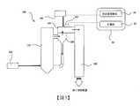
以下,參閱圖式,對用於實施本發明的形態(以下,簡稱為“本實施形態”。)進行詳細說明。但是,以下的實施形態係用於說明本發明的例示,並不意圖將本發明限定於以下內容。本發明能夠在其主旨之範圍內進行適當變形而實施。另外,對相同的要素附加相同的符號,並省略重複說明。又,關於上下左右等的位置關係,只要沒有特別說明,係依據圖式所示之位置關係者。此外,圖式的尺寸比率並不限定於圖式的比率。(第1實施形態)參閱圖1對第1實施形態中的具備防腐裝置之燃燒設備進行說明。圖1係表示本發明的第1實施形態之概略圖。如圖1所示,燃燒設備10具備供給燃燒對象物且在爐內燃燒前述燃燒對象物之燃燒爐20、測量已燃燒燃燒對象物而得之燃燒氣體中的各成份之測量單元30及藉由與在燃燒爐20中產生之燃燒氣體的熱交換而過熱之過熱器40。又,燃燒爐20中具備向爐內供給燃燒對象物之燃燒對象物供給器22。測量單元30中具備向燃燒氣體供給腐蝕抑制劑之腐蝕抑制劑供給裝置31,進而,在燃燒設備10中具備與測量單元30及腐蝕抑制劑供給裝置31中的每個電連接之控制單元50。在本實施形態中,測量單元30、腐蝕抑制劑供給裝置31及控制單元50發揮作為防腐裝置的作用。另外,在圖1中,粗箭頭表示燃燒氣體的流動方向。又,在以下的各圖中,一點虛線表示電信號的路徑。燃燒設備10並無特別限定,能夠列舉以藉由在燃燒爐20中產生之燃燒氣體與過熱器40的熱交換來使蒸汽過熱並用於發電之所謂鍋爐作為例子。又,燃燒設備10並無特別限定,除了主要用於火力發電業務用之、單流鍋爐、循環鍋爐、廢熱回收鍋爐以外,還可以為產業用途中使用之循環流化床鍋爐(CFB)、流化床鍋爐(BFB)、等中的任一個。如圖1所示,燃燒爐20例如構成為縱長的筒狀,並在爐內燃燒從燃燒對象物供給器22供給之燃燒對象物。作為燃燒對象物,只要為可燃物則並無特別限定,例如,能夠使用包含Na、K等鹼金屬鹽之生質燃料、包含鉛或鋅等重金屬之廢物衍生燃料。若從燃燒對象物供給器22供給到燃燒爐20之燃燒對象物被燃燒,則在爐內產生燃燒氣體。又,雖然省略圖式,但是能夠在燃燒爐20的爐壁設置水管,並藉由將水管暴露於燃燒爐20內的燃燒氣體來產生飽和蒸汽。燃燒氣體中包括藉由燃燒對象物的燃燒而產生之第1測量對象及第2測量對象。第1測量對象與第2測量對象係不同之物質,第2測量對象在與第1測量對象相同的波長帶具有吸收光譜,並且在與第1測量對象不同的波長帶具有單獨的吸收光譜。例如,作為第1測量對象,可列舉藉由生質燃料的燃燒而產生之KCl、NaCl、藉由廢物衍生燃料的燃燒而產生之ZnCl2等低熔點的熔融鹽。第2測量對象例如可列舉藉由燃燒而產生之木炭燃燒灰(fly ash(飛灰)、bottom ash(爐底灰))等固體粒子。在燃燒爐20中產生之燃燒氣體在包括第1測量對象及第2測量對象之同時被送到測量單元30。測量單元30係用於測量燃燒氣體內的第1測量對象的濃度之裝置。在測量單元30中,測量燃燒氣體中的與第1測量對象及第2測量對象對應之透射光強度I1及I2。測量單元30中的測量對象的濃度的測量利用吸光光度分析法,例如利用紫外吸光光度分析法。使用圖2對本實施形態的測量單元30進行說明。圖2係用於說明第1實施形態中的測量單元的構成之概略圖。在圖2中,細箭頭表示從發光二極體照射之光的軌道,粗箭頭表示燃燒氣體的流動方向。如圖2所示,測量單元30中設置有發光器32及分光計34。又,測量單元30設置有從燃燒爐20輸送之燃燒氣體的流路39,並且構成為能夠測量流過流路39之燃燒氣體中的第1測量對象及第2測量對象的濃度。另外,在圖1中,示出為相對於測量單元30從紙面左方朝向右方輸送燃燒氣體,但在圖2中,為了說明,以燃燒氣體的流動方向成為從紙面下方朝向上方之方式示出測量單元30。發光器32具備光源部32A及光源部32B,前述光源部32A具備射出包括第1測量對象的吸收光譜之吸收波長帶的照射光之發光二極體,前述光源部32B具備射出包括第2測量對象的吸收光譜且與前述第1測量對象的吸收光譜不同的吸收光譜之吸收波長帶的照射光之發光二極體。測量單元30朝向流過流路39之燃燒氣體,從各光源部射出吸收波長帶不同的照射光。如上所述,光源部32A及32B中設置有發光二極體。在本實施形態中,在燃燒氣體中的第1測量對象及第2測量對象的測量中,由於使用發光二極體代替以往使用之氙燈或汞燈等高壓燈,因此與使用高壓燈之情況相比,光源壽命長。又,由於光源強度的穩定性優異,因此能夠進一步準確地測量測量對象的濃度。用於本實施形態之發光二極體能夠適當地選擇與測量對象的吸收光譜相應之波長者。另外,例如,燃燒氣體中包含除了第1測量對象及第2測量對象以外的其他物質時,從光源部32B射出之光36B的吸收波長帶避開其他物質的吸收光譜而設定為較佳。分光計34中設置有接收從光源部32A射出之照射光之受光部34A及接收從光源部32B射出之照射光之受光部34B。分光計34為具備接收從發光器32照射並透射燃燒氣體之光之光二極體之裝置,並且可發揮透射光強度監視器的功能。如圖2所示,從各光源部射出之光36A及光36B在流路39中通過燃燒氣體,並由各自對應之受光部34A及受光部34B接收。因此,藉由分光計34能夠測量與各光源部相對應之吸收波長區域的光的透射光強度。如圖2所示,測量單元30中設置有分束鏡37,並且構成為從發光器32射出之光36A及光36B的一部分朝向紙面下方反射。被分束鏡37反射之光37A及光37B被光源強度監視用的光二極體38接收。光二極體38具有複數個受光部(省略圖示),以便能夠接收從各光源部射出之光。在測量單元30中,分束鏡37設置成從發光器32照射之光到達燃燒氣體之前反射,並且構成為能夠藉由光二極體38監控設置於發光器32之各光源部的光源強度。另外,亦可以構成為發光器32的光源強度的監控根據由光二極體38接收之光的強度來測量光源強度的波動和各光源部的劣化引起之強度降低,並校正與根據該等測量值預先設定之各發光二極體對應之光源強度。如圖2所示,發光器32、分光計34及光二極體38與控制單元50電連接。若從發光器32射出之光被分光計34接收,則電訊號發送到控制單元50,在控制單元50中,檢測由受光部34A接收之照射光的透射光強度I1及由受光部34B接收之照射光的透射光強度I2。此外,從發光器32射出之光被光二極體38接收,從而電訊號發送到控制單元50,並檢測光源部32A及光源部32B的各光源強度I01及光源強度I02。接著,如圖1所示,控制單元50係具備計算部52及供給量控制部54之CPU等裝置。計算部52根據藉由測量單元30測量之透射光強度或光源強度、亦即,由受光部34A接收之照射光的透射光強度I1及由受光部34B接收之照射光的透射光強度I2計算第1測量對象及第2測量對象的吸光度及透射率。在本實施形態中,根據該值計算第1測量對象的濃度。另外,在圖1等中,控制單元50內示出了計算部52及供給量控制部54,但是該等無需為獨立的裝置,並且能夠構成為在一個CPU中發揮各種作用。對計算部52中的第1測量對象的濃度的計算方法進行具體說明。首先,計算部52使用朗伯特-比爾定律(Lambert-Beer law)(A=-log10(Ix/I0x)=ECl=εcl[A:吸光度、I0x:第x光源部的光源強度、Ix:由第x受光部接收之透射光強度、E:比吸光度、C:具有第x光源部射出之光的吸收光譜之物質的質量對容量百分率濃度、ε:莫耳吸光係數、x:具有第x光源部射出之光的吸收光譜之物質的莫耳濃度、l:光所透射之長度(光路長度)])等,計算燃燒氣體中的具有由光源部32A射出之光的吸收光譜之物質的濃度X1。在此,不僅第1測量對象,而且飛灰等第2測量對象在從光源部32A射出之光的吸收波長帶具有吸收光譜。因此,第2測量對象的濃度對濃度X1有影響,濃度X1成為燃燒氣體中的第1測量對象與第2測量對象的總濃度。接著,計算燃燒氣體中的具有光源部32B所射出之光的吸收光譜之物質的濃度X2。在此,在燃燒氣體中具有由光源部32B射出之光的吸收光譜之物質成為飛灰等第2測量對象,因此濃度X2成為燃燒氣體中的第2測量對象的濃度。因此,藉由從濃度X1除去濃度X2,能夠消除第2測量對象的影響,並計算第1測量對象的濃度。另外,如上所述,作為I0x,使用藉由光二極體38監控之光源強度I01及光源強度I02,作為Ix,使用藉由分光計24監控之透射光強度I1及透射光強度I2。但是,計算部52中的濃度的計算方法並不限定於上述例。接著,如圖1所示,測量單元30設置有向燃燒氣體供給腐蝕抑制劑之腐蝕抑制劑供給裝置31。腐蝕抑制劑係藉由與第1測量對象反應而降低第1測量對象的濃度之物質。腐蝕抑制劑能夠使用具有與第1測量對象化學反應並藉由氧化還原反應等而將第1測量對象作為另一化合物之作用之物質。作為這樣的腐蝕抑制劑,例如,燃燒對象物係包含KCl等之生質燃料時,可列舉硫酸銨((NH4)SO4)、硫酸鋁(Al4(SO4)3)、硫(Elemental Sulphur:元素硫)等硫成份。又,作為腐蝕抑制劑,亦可以使用能夠物理吸附於第1測量對象並降低第1測量對象本身的濃度之微粒等。腐蝕抑制劑供給裝置31與控制單元50中的供給量控制部54電連接。腐蝕抑制劑供給裝置31由控制單元50控制,並藉由控制單元50的供給量控制部54控制供給的時序和腐蝕抑制劑的供給量。在本實施形態中,控制單元50根據藉由計算部52計算之燃燒氣體中的第1測量對象的濃度,藉由供給量控制部54進行控制,以使從腐蝕抑制劑供給裝置31供給之腐蝕抑制劑的供給量相對於第1測量對象的存在量變得合適。儘管沒有特別限定,但是控制單元50能夠控制燃燒氣體中的腐蝕抑制劑的供給量,以使腐蝕抑制劑的存在量相對於第1測量對象的存在量不會多或少。在測量單元30中若將腐蝕抑制劑供給到燃燒氣體中,則燃燒氣體中的第1測量對象的濃度降低。在本實施形態中,構成為將第1測量對象的濃度降低之燃燒氣體從測量單元30發送到過熱器40。在過熱器40內設置省略圖示之蒸汽管。藉由燃燒爐20的熱而產生之飽和蒸汽在蒸汽管內流通,藉由燃燒氣體與過熱器40的熱交換來過熱飽和蒸汽。從過熱器40排出之燃燒氣體發送到設置於過熱器40的下段之各設備(下游側裝置)。又,藉由過熱器40過熱之飽和蒸汽例如能夠用於發電渦輪的驅動等。如上所述,在本實施形態中,藉由燃燒爐20燃燒燃燒對象物,並從具備各發光二極體之光源部32A及光源部32B朝向已燃燒燃燒對象物之燃燒氣體照射包括藉由前述燃燒對象物的燃燒而產生之第1測量對象的吸收光譜之吸收波長帶的照射光、及包括藉由前述燃燒對象物的燃燒而產生之第2測量對象的吸收光譜且與第1測量對象的吸收光譜不同的吸收光譜之吸收波長帶的照射光,能夠藉由各受光部34A或受光部34B接收從各光源部射出之照射光,並根據藉由該等各受光部接收之照射光的透射光強度I1及透射光強度I2,藉由計算部計算第1測量對象及第2測量對象的吸光度和/或透射率,並且能夠根據該值計算第1測量對象的濃度。這樣,在本實施形態中,通過在複數個光源部使用發光二極體,能夠提供一種光源壽命長且能夠測量包含具有相同的吸收波長之兩種以上的物質之混合物中的物質的吸光度、透射率、濃度之防腐裝置及防腐方法。又,由於發光二極體的光源強度的穩定性優異,因此能夠更準確地計算第1測量對象的吸光度、透射率、濃度。又,在本實施形態中,根據藉由計算部52計算之第1測量對象的濃度控制腐蝕抑制劑的供給量,並將腐蝕抑制劑供給到燃燒氣體。因此,由於能夠相對於燃燒氣體中的第1測量對象的存在量供給適當量的腐蝕抑制劑,因此能夠有效地降低第1測量對象的濃度,並有效地抑制基於第1測量對象之燃燒設備10內的各裝置內的腐蝕。另外,在本實施形態中,對計算第1測量對象及第2測量對象的吸光度和/或透射率,並由該值計算第1測量對象的濃度之樣態進行了說明,但是,本發明並不限定於該樣態,亦可以為如下樣態:不計算第1測量對象的濃度,而在計算部52中僅計算第1測量對象的吸光度和/或透射率,並根據該值實施後續製程。(第2實施形態)參閱圖3對第2實施形態中的具備防腐裝置之燃燒設備進行說明。圖3係表示本發明的第2實施形態之概略圖。在本實施形態中,以作為燃燒對象物使用包含KCl作為第1測量對象之生質燃料,又,作為腐蝕抑制劑使用硫成份,並且,作為燃燒爐具備循環流化床鍋爐(CFB)之燃燒設備為例進行說明。如圖3所示,燃燒設備100具備供給生質燃料,並在爐內燃燒生質燃料之燃燒爐120、從已燃燒生質燃料之燃燒氣體分離固體成份之旋風器130、測量燃燒氣體中的各成份之測量單元140及藉由與燃燒氣體的熱交換而被過熱之過熱器150。又,燃燒爐120中設置有向爐內供給生質燃料之燃料供給器122。測量單元140中設置有向燃燒氣體供給硫成份之腐蝕抑制劑供給裝置148,在燃燒設備100中進一步設置有與測量單元140及腐蝕抑制劑供給裝置148中的每個電連接之控制單元50。在本實施形態中,測量單元140和控制單元50發揮防腐裝置的作用。燃燒爐120構成為縱長的筒狀,並在爐內燃燒從燃料供給器122供給之生質燃料。燃燒爐120係使生質燃料在流化床中流動之同時燃燒之流化床爐。又,如後述,燃燒爐120係既定粒徑以上的固體成份藉由旋風器130返回之循環流化床爐。燃燒爐120內的溫度並無特別限定,但是能夠將燃燒氣體的溫度設定成為800~1000℃左右。若燃燒從燃料供給器122供給到燃燒爐120之生質燃料,則產生燃燒氣體。又,雖然省略圖式,但是能夠在燃燒爐120的爐壁設置水管,並藉由將水管暴露於燃燒爐120內的燃燒氣體來產生飽和蒸汽。又,藉由生質燃料的燃燒,燃燒氣體中含有作為第1測量對象之KCl,並且含有藉由該燃燒產生之飛灰(fly ash)。在本實施形態中,飛灰成為第2測量對象。又,在本實施形態中,燃燒氣體中除了KCl及飛灰以外,還包含NaCl、後述硫成份中所含有之SO2。在燃燒爐120中產生之燃燒氣體包含該等KCl或飛灰等成份之同時進給到旋風器130。旋風器130係將從燃燒爐120排出之既定的粒徑以上的固體成份從燃燒氣體中分離並返回至燃燒爐120之固體-氣體分離裝置。旋風器130從燃燒氣體分離既定的粒徑以上的固體成份並使其返回至燃燒爐120內,並且將分離該等固體成份之燃燒氣體進給到後段的測量單元140。基於旋風器130之固體成份的篩選粒徑並無特別限定,例如,能夠設定為約20μm。測量單元140係用於計算燃燒氣體內的KCl的吸光度及透射率,並根據該值測量其濃度之裝置。在測量單元140中,測量燃燒氣體中的與KCl(第1測量對象)及飛灰(第2測量對象)對應之透射光強度I1及I2。在本實施形態中,測量測量單元140中的測量對象的濃度時使用紫外吸光光度分析法。使用圖4對本實施形態的測量單元140進行說明。圖4係表示第2實施形態中的測量單元的一個樣態之概略圖。如圖4所示,測量單元140中設置有從旋風器130供給之燃燒氣體流通之主管141及外部測量部142,並且構成為在主管141內流通之燃燒氣體的一部分經由氣體管141A流通到外部測量部142。外部測量部142內設置有發光器144及分光計146,燃燒氣體在發光器144與分光計146之間從紙面左方朝向右方流通。從外部測量部142排出之燃燒氣體經由氣體管141B返回到主管141。外部測量部142的紙面上方設置有發光器144。雖然省略圖示,但是發光器144中設置有第1光源部及第2光源部,前述第1光源部具備射出包括KCl的吸收光譜之吸收波長帶的照射光之發光二極體,前述第2光源部具備射出包括飛灰的吸收光譜且與前述KCl的吸收光譜不同的吸收光譜之吸收波長帶的照射光之發光二極體。在此,關於燃燒氣體中所含有之各成份的吸收光譜的峰值,KCl接近250 nm,NaCl接近240nm,SO2接近220nm及290nm。另一方面,關於飛灰,吸收光譜的波長帶寬,並且在KCl等吸收光譜的波長帶亦具有吸收。因此,在本實施形態中,在第1光源部中使用具有與KCl的吸收光譜對應之約250nm的波長之發光二極體,又,在第2光源部中使用具有約400nm的波長之發光二極體。這樣,藉由將第2光源部的發光二極體的波長設定在不容易受到除了作為第2測量對象之飛灰以外的成份的影響之400nm附近,能夠更準確地計算燃燒氣體中的飛灰的吸光度及透射率、以及濃度。外部測量部142的紙面下方設置有分光計146。雖然省略圖示,但在分光計146中設置有接收從第1光源部射出之波長250nm的照射光之第1受光部及接收從第2光源部射出之波長400nm的照射光之第2受光部。與第1實施形態同樣地,從各光源部射出之照射光透射燃燒氣體並由分別對應之受光部接收。又,雖然省略圖示,但在外部測量部142設置有分束鏡,以使從發光器144照射之光在到達燃燒氣體之前被反射,並且構成為反射從發光器144射出之一部分照射光,並由光源強度監視用光二極體接收。在本實施形態中,與第1實施形態同樣地,藉由該光二極體檢測發光器144的光源強度。如圖3所示,外部測量部142與控制單元50電連接。若從發光器144射出之光被分光計146接收,則電訊號發送到控制單元50,在控制單元50中,檢測由第1受光部接收之波長250nm的照射光的透射光強度I1及由第2受光部接收之波長400nm的照射光的透射光強度I2。此外,從發光器144射出之光被光二極體接收,從而電訊號發送到控制單元50,並檢測第1光源部及第2光源部的各光源強度I01及光源強度I02。另外,在本實施形態中,採用了將外部測量部142設置於使外部測量部142位於過熱器150的前段之主管141中,並測量燃燒氣體中的成份的濃度之方式,但是在外部測量部142設置位置並不限定於此,例如,能夠依據燃燒爐120等需要來適當地選擇。如朗伯特-比爾定律所示,若光路長度增加,則透射率亦相應地降低。因此,如本實施形態那樣使用外部測量部142時,能夠根據外部測量部142的尺寸將光路長度(發光器144與分光計146的距離)設為恆定,因此不受設置該測量部之爐或管的尺寸的影響,能夠在相同條件下檢測透射光強度I1和透射光強度I2。在本實施形態中,控制單元50具備計算部52及供給量控制部54,與第1實施形態同樣地,根據由測量單元140測量之透射光強度I1及透射光強度I2計算作為第1測量對象之KCl的吸光度及透射率,並根據該值計算其濃度。測量單元140設置有向燃燒氣體供給硫成份之腐蝕抑制劑供給裝置148。硫成份中包含例如選自硫酸銨((NH4)SO4)、硫酸鋁(Al4(SO4)3)、硫(Elemental Sulphur)等之至少一種。如下述式所示,硫成份與KCl反應而產生無害的K2SO4,能夠降低KCl的濃度。

Figure 02_image001
如圖3所示,腐蝕抑制劑供給裝置148與控制單元50中的供給量控制部54電連接。腐蝕抑制劑供給裝置148由控制單元50控制,從腐蝕抑制劑供給裝置148供給之硫成份的供給量由供給量控制部54控制。控制單元50根據藉由計算部52計算之燃燒氣體中的KCl的濃度,藉由供給量控制部54進行控制,以使從腐蝕抑制劑供給裝置148供給之硫成份的供給量相對於KCl的存在量變得合適。儘管沒有特別限定,但是控制單元50能夠控制燃燒氣體中的硫成份的供給量,以使硫成份的存在量相對於KCl的存在量不會多或少。若藉由腐蝕抑制劑供給裝置148向燃燒氣體中供給硫成份,則能夠降低燃燒氣體中的KCl的濃度。在本實施形態中,構成為從測量單元140向過熱器150輸送KCl的濃度降低之燃燒氣體。過熱器150內與第1實施形態同樣地設置有省略圖示之配管,藉由燃燒爐120的熱而產生之飽和蒸汽在管內流通,並藉由燃燒氣體與過熱器150的熱交換來過熱飽和蒸汽。從過熱器150排出之燃燒氣體輸送到設置於過熱器150的下游之各設備(下游側裝置)。又,藉由過熱器150過熱之飽和蒸汽例如能夠用於發電渦輪的驅動等。在此,KCl的熔點為約780℃,因此在過熱器150與燃燒氣體的熱交換時,KCl本身附著於過熱器150的內壁等,成為該等裝置腐蝕的原因。此外,KCl氣體的附著促進飛灰的附著。飛灰的附著在過熱器150中成為熱交換效率降低的原因。燃燒設備100為了降低這樣的低品位的生質燃料中所含有之成份帶來之影響,藉由硫成份的供給來降低燃燒氣體中的KCl的濃度。藉此,能夠抑制位於比腐蝕抑制劑供給裝置148更靠後段之位置之過熱器150等被KCl腐蝕,或者由於KCl的存在而使飛灰在過熱器150內附著所導致的熱交換效率的降低。尤其,在過熱器150內,燃燒氣體的溫度藉由熱交換而降低,因此KCl容易凝聚,因此能夠在旋風器130與過熱器150之間的階段供給腐蝕抑制劑為較佳。如上所述,在本實施形態中,在燃燒爐120中燃燒包含KCl之生質燃料,從具備各發光二極體之光源部朝向已燃燒生質燃料之燃燒氣體照射包括KCl的吸收光譜之吸收波長帶的照射光及包括藉由前述生質燃料的燃燒而產生之飛灰的吸收光譜且與KCl的吸收光譜不同之吸收光譜之吸收波長帶的照射光,並藉由各受光部接收從各光源部射出之照射光,根據由該等各受光部接收之照射光的透射光強度I1及透射光強度I2計算KCl的吸光度及透射率,並能夠根據該值藉由計算部計算其濃度。這樣,在本實施形態中,通過在複數個光源部使用發光二極體,能夠提供一種光源壽命長且能夠測量包含具有相同的吸收波長之兩種以上的物質之混合物中的物質的濃度之防腐裝置及防腐方法。又,由於發光二極體的光源強度的穩定性優異,因此能夠更準確地計算KCl的吸光度、透射率及濃度。又,在本實施形態中,根據藉由計算部52計算之KCl的濃度控制硫成份的供給量,並將硫成份供給到燃燒氣體。因此,由於能夠相對於燃燒氣體中的KCl的存在量供給適當量的硫成份,因此能夠有效地降低KCl的濃度,並有效地抑制基於KCl之燃燒設備100內的各裝置內的腐蝕。另外,在本實施形態中,亦對計算KCl及飛灰的吸光度和/或透射率,並由該值計算KCl的濃度之樣態進行了說明,但是,本發明並不限定於該樣態,亦可以為如下樣態:不計算KCl的濃度,而在計算部52中僅計算KCl的吸光度和/或透射率,並根據該值實施後續製程。(其他樣態)在第2實施形態中,對使用具備外部測量部142之測量單元140之樣態進行了說明,但是作為測量單元,亦可以使用具有如圖5所示之結構之測量單元160。圖5係表示第2實施形態中的測量單元的其他樣態之概略圖。如圖5所示,測量單元160具備使從旋風器130供給之燃燒氣體流通之主管141,並在主管141內設置有發光器162及分光計164。在主管141內,燃燒氣體從紙面左方朝向右方流通。又,在主管141的管內,燃燒氣體的流路由於發光器162及分光計164而變窄。藉由以這種方式縮小發光器162與分光計164之間的空間,並能夠以簡單的構成縮短測量單元160中的光路長度(發光器144與分光計146之間的距離)。這樣,藉由將測量單元160中的光路長度適當地調整為適合於成為測量對象之鍋爐中的氣體的種類和濃度之長度,能夠提高燃燒氣體中的各成份的濃度的測量精度。又,在上述各實施形態中,設為使用第1光源部及第2光源部,根據藉由計算部計算之第1測量對象的濃度供給腐蝕抑制劑之構成,但是本發明並不限定於該等樣態,例如,亦能夠使用3種光源部。例如,除了第1光源部及第2光源部等以外,還能夠設置第3光源部和第3受光部,前述第3光源部具備射出如下吸收波長帶的照射光之發光二極體,前述吸收波長帶包括由腐蝕抑制劑產生之第3測量對象的吸收光譜且與第1測量對象及第2測量對象的吸收光譜不同的吸收光譜,前述第3受光部接收從第3光源部射出之照射光。在這樣的樣態中,計算部能夠構成為根據由第3受光部接收之照射光的透射光強度I3及由第2受光部接收之照射光的透射光強度I2計算燃燒氣體中的第3測量對象的吸光度及透射率,並根據該值計算其濃度,供給量控制部根據藉由計算部計算之第1測量對象及第3測量對象的吸光度或透射率或根據該值計算之濃度控制前述腐蝕抑制劑的供給量。作為這樣的例,例如可列舉如下樣態:作為燃燒對象物使用生質燃料,將第1測量對象設為KCl,將第2測量對象設為飛灰,將第3測量對象設為由硫成份產生之SO2,在第1光源部中使用具有與KCl的吸收光譜對應之約250nm的波長之發光二極體,又,在第2光源部中使用具有約400nm的波長之發光二極體,在第3光源部中使用具有與SO2的吸收光譜對應之約290nm的波長之發光二極體。依該樣態,能夠計算由作為腐蝕抑制劑供給之硫成份產生之SO2的吸光度及透射率,並根據該值計算其濃度,因此根據SO2的濃度判斷為硫成份在供給量控制部中供給過量時,能夠減少硫成份的供給量,並供給更合適的量的腐蝕抑制劑。藉由上述發明的實施形態說明之實施的樣態能夠根據用途適當組合或加以變更或改良。又,本發明並不限定於上述實施形態的記載。Hereinafter, referring to the drawings, a mode for implementing the present invention (hereinafter referred to simply as "this embodiment") will be described in detail. However, the following embodiments are examples for explaining the present invention, and are not intended to limit the present invention to the following contents. The present invention can be suitably modified and implemented within the scope of its gist. In addition, the same symbols are attached to the same elements, and repeated descriptions are omitted. In addition, as for the positional relationship of up, down, left, and right, unless otherwise specified, it is based on the positional relationship shown in the drawings. In addition, the size ratio of the drawing is not limited to the ratio of the drawing. (First Embodiment) With reference to Fig. 1, a combustion facility equipped with an anti-corrosion device in the first embodiment will be described. Fig. 1 is a schematic diagram showing the first embodiment of the present invention. As shown in FIG. 1, thecombustion equipment 10 includes acombustion furnace 20 that supplies a combustion target and burns the aforementioned combustion target in the furnace, ameasuring unit 30 that measures the components in the combustion gas obtained by the burned combustion target, and Thesuperheater 40 superheats by exchanging heat with the combustion gas generated in thecombustion furnace 20. In addition, thecombustion furnace 20 includes acombustion target supplier 22 that supplies the combustion target into the furnace. Themeasurement unit 30 is provided with a corrosioninhibitor supply device 31 that supplies the corrosion inhibitor to the combustion gas, and further, thecombustion equipment 10 is provided with acontrol unit 50 electrically connected to each of themeasurement unit 30 and the corrosioninhibitor supply device 31. In this embodiment, themeasurement unit 30, the corrosioninhibitor supply device 31, and thecontrol unit 50 function as anticorrosion devices. In addition, in FIG. 1, the thick arrow indicates the flow direction of the combustion gas. In addition, in the following figures, a dotted line indicates the path of an electric signal. Thecombustion facility 10 is not particularly limited, and a so-called boiler that superheats steam by heat exchange between the combustion gas generated in thecombustion furnace 20 and thesuperheater 40 and uses it for power generation can be cited as an example. In addition, thecombustion equipment 10 is not particularly limited. In addition to single-flow boilers, circulating boilers, and waste heat recovery boilers, which are mainly used for thermal power generation business, it can also be circulating fluidized bed boilers (CFB), flow Any one of a fluidized bed boiler (BFB), etc. As shown in FIG. 1, thecombustion furnace 20 is configured, for example, in a longitudinally long cylindrical shape, and burns the combustion target supplied from thecombustion target supplier 22 in the furnace. The combustion target is not particularly limited as long as it is combustible. For example, a biomass fuel containing alkali metal salts such as Na and K, and a waste-derived fuel containing heavy metals such as lead or zinc can be used. When the combustion target supplied from thecombustion target supplier 22 to thecombustion furnace 20 is burned, combustion gas is generated in the furnace. In addition, although the drawing is omitted, a water pipe can be provided on the furnace wall of thecombustion furnace 20, and saturated steam can be generated by exposing the water pipe to the combustion gas in thecombustion furnace 20. The combustion gas includes the first measurement object and the second measurement object generated by the combustion of the combustion object. The first measurement object and the second measurement object are different substances, and the second measurement object has an absorption spectrum in the same wavelength band as the first measurement object, and has a separate absorption spectrum in a wavelength band different from the first measurement object. For example, as the first measurement object, low-melting molten salts such as KCl and NaCl produced by the combustion of biomass fuels, and ZnCl2 produced by the combustion of waste-derived fuels can be cited. The second measurement target includes, for example, solid particles such as charcoal combustion ash (fly ash (fly ash), bottom ash (furnace bottom ash)) generated by combustion. The combustion gas generated in thecombustion furnace 20 is sent to themeasurement unit 30 while including the first measurement object and the second measurement object. Themeasuring unit 30 is a device for measuring the concentration of the first measuring object in the combustion gas.In the measurement unit 30, the transmitted light intensities I 1 and I2 corresponding to the first measurement object and the second measurement object in the combustion gas are measured. The measurement of the concentration of the measurement object in themeasurement unit 30 uses an absorbance photometric method, for example, an ultraviolet absorbance photometric method. Themeasurement unit 30 of this embodiment will be described with reference to FIG. 2. Fig. 2 is a schematic diagram for explaining the configuration of the measuring unit in the first embodiment. In Fig. 2, the thin arrows indicate the trajectory of the light irradiated from the light-emitting diode, and the thick arrows indicate the flow direction of the combustion gas. As shown in FIG. 2, alight emitter 32 and aspectrometer 34 are provided in themeasuring unit 30. In addition, themeasurement unit 30 is provided with aflow path 39 of the combustion gas sent from thecombustion furnace 20 and is configured to be able to measure the concentration of the first measurement object and the second measurement object in the combustion gas flowing through theflow path 39. In addition, in FIG. 1, it is shown that the combustion gas is transported from the left to the right of the paper with respect to themeasurement unit 30. However, in FIG. 2, for the purpose of explanation, the flow direction of the combustion gas is shown as being from the bottom to the top of the paper.出Measurement unit 30. Thelight emitter 32 includes alight source unit 32A and alight source unit 32B. Thelight source unit 32A includes a light emitting diode that emits irradiated light in the absorption wavelength band including the absorption spectrum of the first measurement object. Thelight source unit 32B includes a second measurement object. The light emitting diode of the irradiated light in the absorption wavelength band of the absorption spectrum different from the absorption spectrum of the first measurement object. Themeasurement unit 30 faces the combustion gas flowing through theflow path 39, and emits irradiation light having different absorption wavelength bands from each light source section. As described above, light-emitting diodes are provided in thelight source sections 32A and 32B. In this embodiment, in the measurement of the first measurement object and the second measurement object in the combustion gas, since light-emitting diodes are used instead of high-pressure lamps such as xenon lamps or mercury lamps used in the past, it is similar to the case of using high-pressure lamps. Compared with, the light source has a long life. In addition, since the stability of the intensity of the light source is excellent, the concentration of the measurement object can be measured more accurately. The light-emitting diode used in this embodiment can be appropriately selected with a wavelength corresponding to the absorption spectrum of the measurement object. In addition, for example, when the combustion gas contains substances other than the first measurement object and the second measurement object, it is preferable to set the absorption wavelength band of the light 36B emitted from thelight source section 32B to avoid the absorption spectrum of the other substances. Thespectrometer 34 is provided with alight receiving unit 34A which receives the irradiation light emitted from thelight source unit 32A and alight receiving unit 34B which receives the irradiation light emitted from thelight source unit 32B. Thespectrometer 34 is a device provided with a light diode that receives light irradiated from thelight emitter 32 and transmitted through the combustion gas, and can function as a monitor of transmitted light intensity. As shown in FIG. 2, thelight 36A and the light 36B emitted from each light source section pass through the combustion gas in theflow path 39 and are received by the correspondinglight receiving section 34A andlight receiving section 34B. Therefore, thespectrometer 34 can measure the transmitted light intensity of light in the absorption wavelength region corresponding to each light source section. As shown in FIG. 2, the measuringunit 30 is provided with abeam splitter 37 and is configured to reflect a part of the light 36A and the light 36B emitted from thelight emitter 32 toward the bottom of the paper. The light 37A and the light 37B reflected by thebeam splitter 37 are received by thelight diode 38 for monitoring the intensity of the light source. Thelight diode 38 has a plurality of light receiving parts (not shown) so as to be able to receive light emitted from each light source part. In themeasurement unit 30, thebeam splitter 37 is installed to reflect the light irradiated from thelight emitter 32 before reaching the combustion gas, and is configured to be able to monitor the light source intensity of each light source part provided in thelight emitter 32 by thelight diode 38. In addition, the monitoring of the light source intensity of thelight emitter 32 may be configured to measure fluctuations in the light source intensity and the intensity reduction caused by the deterioration of each light source unit based on the intensity of the light received by thephotodiode 38, and calibrate them based on these measured values. The preset light source intensity corresponding to each light-emitting diode. As shown in FIG. 2, thelight emitter 32, thespectrometer 34 and thelight diode 38 are electrically connected to thecontrol unit 50. If the light emitted from thelight emitter 32 is received by thespectrometer 34, the electrical signal is sent to thecontrol unit 50. In thecontrol unit 50, the transmitted light intensity I1 of the irradiated light received by thelight receiving unit 34A is detected and received by thelight receiving unit 34B The transmitted light intensity of the irradiated light I2 . In addition, the light emitted from thelight emitter 32 is received by thelight diode 38, so that the electrical signal is sent to thecontrol unit 50, and the light source intensity I01 and the light source intensity I02 of thelight source unit 32A and thelight source unit 32B are detected. Next, as shown in FIG. 1, thecontrol unit 50 is a device such as a CPU including acalculation unit 52 and a supplyamount control unit 54. Thecalculation unit 52 is based on the transmitted light intensity or the light source intensity measured by the measuringunit 30, that is, the transmitted light intensity I1of the irradiated light received by the light receiving unit 34A and the transmitted light intensity I 2 of the irradiated light received by thelight receiving unit 34B. Calculate the absorbance and transmittance of the first measurement object and the second measurement object. In this embodiment, the concentration of the first measurement object is calculated based on this value. In addition, in FIG. 1 and the like, thecalculation unit 52 and the supplyamount control unit 54 are shown in thecontrol unit 50, but these need not be independent devices, and can be configured to perform various functions in one CPU. The calculation method of the concentration of the first measurement object in thecalculation unit 52 will be specifically described. First, thecalculation unit 52 uses Lambert-Beer law (A=-log10 (Ix /I0x )=ECl=εcl [A: absorbance, I0x : light source intensity of the x-th light source unit , Ix : The intensity of the transmitted light received by the x-th light-receiving part, E: Specific absorbance, C: The mass-to-capacity percentage concentration of the substance with the absorption spectrum of the light emitted by the x-th light source part, ε: Mohr absorption coefficient, x : The molar concentration of the substance with the absorption spectrum of the light emitted by the x-th light source, l: the length of the light transmitted (optical path length)), etc., and calculate the absorption spectrum of the light emitted by thelight source 32A in the combustion gas The concentration of the substance X1. Here, not only the first measurement object but also the second measurement object such as fly ash has an absorption spectrum in the absorption wavelength band of the light emitted from thelight source unit 32A. Therefore, the concentration of the second measurement object has an influence on the concentration X1, and the concentration X1 becomes the total concentration of the first measurement object and the second measurement object in the combustion gas. Next, the concentration X2 of the substance having the absorption spectrum of the light emitted by thelight source section 32B in the combustion gas is calculated. Here, in the combustion gas, the substance having the absorption spectrum of the light emitted by thelight source unit 32B becomes the second measurement target such as fly ash, and therefore the concentration X2 becomes the concentration of the second measurement target in the combustion gas. Therefore, by removing the concentration X2 from the concentration X1, the influence of the second measurement object can be eliminated, and the concentration of the first measurement object can be calculated. In addition, as described above, as I0x , the light source intensity I01 and the light source intensity I02 monitored by thephotodiode 38 are used, and as Ix, the transmitted light intensity I 1 and the transmitted light intensity monitored by the spectrometer 24 are used I2 . However, the calculation method of the concentration in thecalculation unit 52 is not limited to the above example. Next, as shown in FIG. 1, themeasurement unit 30 is provided with a corrosioninhibitor supply device 31 that supplies a corrosion inhibitor to the combustion gas. The corrosion inhibitor is a substance that reduces the concentration of the first measurement object by reacting with the first measurement object. As the corrosion inhibitor, it is possible to use a substance that has a chemical reaction with the first measurement object and uses the first measurement object as another compound through an oxidation-reduction reaction or the like. Examples of such corrosion inhibitors include ammonium sulfate ((NH4 )SO4 ), aluminum sulfate (Al4 (SO4 )3 ), sulfur (Elemental Sulphur: elemental sulfur) and other sulfur components. In addition, as the corrosion inhibitor, it is also possible to use particles that can physically adsorb to the first measurement object and reduce the concentration of the first measurement object itself. The corrosioninhibitor supply device 31 is electrically connected to the supplyamount control unit 54 in thecontrol unit 50. The corrosioninhibitor supply device 31 is controlled by thecontrol unit 50, and the supplyamount control section 54 of thecontrol unit 50 controls the timing of the supply and the supply amount of the corrosion inhibitor. In this embodiment, thecontrol unit 50 controls the supplyamount control unit 54 based on the concentration of the first measurement object in the combustion gas calculated by thecalculation unit 52 so that the corrosioninhibitor supply device 31 supplies corrosion The supply amount of the inhibitor becomes appropriate relative to the existing amount of the first measurement object. Although not particularly limited, thecontrol unit 50 can control the supply amount of the corrosion inhibitor in the combustion gas so that the amount of the corrosion inhibitor does not increase or decrease with respect to the amount of the first measurement object. When the corrosion inhibitor is supplied to the combustion gas in themeasurement unit 30, the concentration of the first measurement object in the combustion gas decreases. In this embodiment, the combustion gas whose concentration of the first measurement object is reduced is sent from themeasurement unit 30 to thesuperheater 40. A steam pipe (not shown) is provided in thesuperheater 40. The saturated steam generated by the heat of thecombustion furnace 20 circulates in the steam pipe, and the saturated steam is superheated by the heat exchange between the combustion gas and thesuperheater 40. The combustion gas discharged from thesuperheater 40 is sent to each device (downstream side device) installed in the lower stage of thesuperheater 40. In addition, the saturated steam superheated by thesuperheater 40 can be used, for example, for driving a power generation turbine. As described above, in the present embodiment, the burning object is burned by thecombustion furnace 20, and the burning gas irradiation from thelight source section 32A and thelight source section 32B provided with each light-emitting diode to the burned burning object includes the aforementioned The irradiated light in the absorption wavelength band of the absorption spectrum of the first measurement object generated by the combustion of the burning object, and the absorption spectrum of the second measurement object generated by the combustion of the aforementioned combustion object, and that is the same as that of the first measurement object. The irradiated light in the absorption wavelength bands of the absorption spectra with different absorption spectra can receive the irradiated light emitted from each light source section by eachlight receiving section 34A orlight receiving section 34B, and according to the transmission of the irradiated light received by eachlight receiving section 34A or 34B. The light intensity I1 and the transmitted light intensity I2 are calculated by the calculation unit to calculate the absorbance and/or transmittance of the first measurement object and the second measurement object, and the concentration of the first measurement object can be calculated based on the values. In this way, in this embodiment, by using light-emitting diodes in a plurality of light sources, it is possible to provide a light source that has a long life and can measure the absorbance and transmittance of a substance in a mixture of two or more substances with the same absorption wavelength. Anti-corrosion device and method of anti-corrosion rate and concentration. In addition, since the light source intensity of the light emitting diode is excellent in stability, the absorbance, transmittance, and concentration of the first measurement object can be calculated more accurately. In addition, in this embodiment, the supply amount of the corrosion inhibitor is controlled based on the concentration of the first measurement object calculated by thecalculation unit 52, and the corrosion inhibitor is supplied to the combustion gas. Therefore, since it is possible to supply an appropriate amount of corrosion inhibitor relative to the amount of the first measurement object in the combustion gas, the concentration of the first measurement object can be effectively reduced, and thecombustion equipment 10 based on the first measurement object can be effectively suppressed. Corrosion within each device. In addition, in this embodiment, the absorbance and/or transmittance of the first measurement object and the second measurement object are calculated, and the concentration of the first measurement object is calculated from the value. However, the present invention does not It is not limited to this aspect, and may also be the following aspect: the concentration of the first measurement object is not calculated, but only the absorbance and/or transmittance of the first measurement object is calculated in thecalculation section 52, and subsequent processes are implemented based on this value . (Second Embodiment) With reference to Fig. 3, a combustion facility equipped with an anticorrosive device in a second embodiment will be described. Fig. 3 is a schematic diagram showing a second embodiment of the present invention. In this embodiment, the biomass fuel containing KCl as the first measurement object is used as the combustion target, the sulfur component is used as the corrosion inhibitor, and the combustion furnace is equipped with a circulating fluidized bed boiler (CFB) combustion The device is described as an example. As shown in FIG. 3, thecombustion equipment 100 includes acombustion furnace 120 that supplies biomass fuel and burns the biomass fuel in the furnace, acyclone 130 that separates solid components from the combustion gas of the burned biomass fuel, and measures the combustion gas in the combustion gas. The measuringunit 140 of each component and thesuperheater 150 overheated by heat exchange with the combustion gas. In addition, thecombustion furnace 120 is provided with afuel supplier 122 that supplies biomass fuel into the furnace. Themeasurement unit 140 is provided with a corrosioninhibitor supply device 148 for supplying sulfur components to the combustion gas, and thecombustion equipment 100 is further provided with acontrol unit 50 electrically connected to each of themeasurement unit 140 and the corrosioninhibitor supply device 148. In this embodiment, themeasurement unit 140 and thecontrol unit 50 function as an anti-corrosion device. Thecombustion furnace 120 is configured in a longitudinally long cylindrical shape, and burns the biomass fuel supplied from thefuel supplier 122 in the furnace. Thecombustion furnace 120 is a fluidized bed furnace that burns biomass fuel while flowing in the fluidized bed. In addition, as described later, thecombustion furnace 120 is a circulating fluidized bed furnace in which solid components of a predetermined particle size or more are returned by thecyclone 130. The temperature in thecombustion furnace 120 is not particularly limited, but the temperature of the combustion gas can be set to approximately 800 to 1000°C. When the biomass fuel supplied from thefuel supplier 122 to thecombustion furnace 120 is burned, combustion gas is generated. In addition, although the drawing is omitted, a water pipe can be provided on the furnace wall of thecombustion furnace 120, and saturated steam can be generated by exposing the water pipe to the combustion gas in thecombustion furnace 120. In addition, due to the combustion of the biomass fuel, the combustion gas contains KCl, which is the first measurement object, and also contains fly ash generated by the combustion. In this embodiment, fly ash becomes the second measurement target. In the present embodiment, in addition to KCl and fly ash, the combustion gas also contains NaCl and SO2 contained in the sulfur component described below. The combustion gas generated in thecombustion furnace 120 contains the KCl or fly ash and other components and is fed to thecyclone 130 at the same time. Thecyclone 130 is a solid-gas separation device that separates solid components with a predetermined particle size or more discharged from thecombustion furnace 120 from the combustion gas and returns to thecombustion furnace 120. Thecyclone 130 separates solid components above a predetermined particle size from the combustion gas and returns it to thecombustion furnace 120, and feeds the combustion gas from which the solid components are separated to themeasurement unit 140 in the subsequent stage. The screening particle size based on the solid content of thecyclone 130 is not particularly limited, and can be set to about 20 μm, for example. The measuringunit 140 is a device for calculating the absorbance and transmittance of KCl in the combustion gas, and measuring its concentration based on the value.In the measurement unit 140, the transmitted light intensities I 1 and I2 corresponding to KCl (first measurement object) and fly ash (second measurement object) in the combustion gas are measured. In the present embodiment, when measuring the concentration of the measurement object in themeasurement unit 140, an ultraviolet absorbance spectroscopy method is used. Themeasurement unit 140 of this embodiment will be described with reference to FIG. 4. Fig. 4 is a schematic diagram showing one aspect of the measuring unit in the second embodiment. As shown in FIG. 4, themeasurement unit 140 is provided with amain pipe 141 through which the combustion gas supplied from thecyclone 130 flows and anexternal measurement unit 142, and is configured such that a part of the combustion gas circulating in themain pipe 141 flows to the outside through thegas pipe 141A Themeasurement unit 142. Anilluminator 144 and aspectrometer 146 are provided in theexternal measurement unit 142, and the combustion gas flows between the illuminator 144 and thespectrometer 146 from the left to the right of the paper. The combustion gas discharged from theexternal measurement part 142 returns to themain pipe 141 via thegas pipe 141B. Alight emitter 144 is provided above the paper surface of theexternal measurement unit 142. Although not shown, thelight emitter 144 is provided with a first light source section and a second light source section. The first light source section is provided with a light emitting diode that emits irradiated light in the absorption wavelength band including the absorption spectrum of KCl. The light source unit is provided with a light emitting diode that emits irradiated light including an absorption spectrum of fly ash and an absorption wavelength band of an absorption spectrum different from the absorption spectrum of the aforementioned KCl. Here, regarding the peak of the absorption spectrum of each component contained in the combustion gas, KCl is close to 250 nm, NaCl is close to 240 nm, and SO2 is close to 220 nm and 290 nm. On the other hand, with regard to fly ash, the wavelength bandwidth of the absorption spectrum, and also has absorption in the wavelength band of the absorption spectrum such as KCl. Therefore, in this embodiment, a light-emitting diode having a wavelength of approximately 250 nm corresponding to the absorption spectrum of KCl is used in the first light source unit, and a light-emitting diode having a wavelength of approximately 400 nm is used in the second light source unit. Polar body. In this way, by setting the wavelength of the light-emitting diode of the second light source section to around 400nm, which is not easily affected by components other than fly ash, which is the second measurement object, it is possible to more accurately calculate the fly ash in the combustion gas The absorbance and transmittance, as well as the concentration. Aspectrometer 146 is provided below the paper surface of theexternal measurement unit 142. Although not shown in the figure, thespectrometer 146 is provided with a first light-receiving unit that receives the irradiated light with a wavelength of 250nm emitted from the first light source unit and a second light-receiver that receives the irradiated light with a wavelength of 400nm emitted from the second light source unit. . As in the first embodiment, the irradiated light emitted from each light source section transmits the combustion gas and is received by the corresponding light-receiving section. In addition, although not shown, a beam splitter is provided in theexternal measurement section 142 so that the light irradiated from thelight emitter 144 is reflected before reaching the combustion gas, and it is configured to reflect a part of the irradiated light emitted from thelight emitter 144. And it is received by the light diode for monitoring the intensity of the light source. In this embodiment, similar to the first embodiment, the light source intensity of thelight emitter 144 is detected by the photodiode. As shown in FIG. 3, theexternal measurement unit 142 is electrically connected to thecontrol unit 50. If the light emitted from thelight emitter 144 is received by thespectrometer 146, the electrical signal is sent to thecontrol unit 50. In thecontrol unit 50, the transmitted light intensity I1 of the irradiated light with a wavelength of 250 nm received by the first light receiving unit and theThe transmitted light intensity I 2 of the irradiated light having a wavelength of 400 nm received by the second light receiving unit. In addition, the light emitted from thelight emitter 144 is received by the photodiode, so that the electric signal is sent to thecontrol unit 50, and the light source intensity I01 and the light source intensity I02 of the first light source part and the second light source part are detected. In addition, in this embodiment, theexternal measurement unit 142 is installed in themain pipe 141 in the front stage of thesuperheater 150, and the concentration of the components in the combustion gas is measured. However, the external measurement unit The installation position of 142 is not limited to this. For example, it can be appropriately selected according to the needs of thecombustion furnace 120 and the like. As shown by the Lambert-Beer law, if the length of the optical path increases, the transmittance decreases accordingly. Therefore, when theexternal measurement unit 142 is used as in the present embodiment, the optical path length (the distance between thelight emitter 144 and the spectrometer 146) can be made constant according to the size of theexternal measurement unit 142, and therefore it is not affected by the furnace or the oven in which the measurement unit is installed. The influence of the size of the tube can detect the transmitted light intensity I1 and the transmitted light intensity I2 under the same conditions. In this embodiment, thecontrol unit 50 includes acalculation unit 52 and a supplyamount control unit 54. Similar to the first embodiment, it is calculated based on the transmitted light intensity I1 and the transmitted light intensity I2 measured by the measuringunit 140 as the first Measure the absorbance and transmittance of KCl of the object, and calculate its concentration based on this value. Themeasurement unit 140 is provided with a corrosioninhibitor supply device 148 that supplies sulfur components to the combustion gas. The sulfur component includes, for example, at least one selected from the group consisting of ammonium sulfate ((NH4 )SO4 ), aluminum sulfate (Al4 (SO4 )3 ), and sulfur (Elemental Sulphur). As shown in the following formula, the sulfur component reacts with KCl to produce harmless K2 SO4 , and the concentration of KCl can be reduced.
Figure 02_image001
As shown in FIG. 3, the corrosioninhibitor supply device 148 is electrically connected to the supplyamount control unit 54 in thecontrol unit 50. The corrosioninhibitor supply device 148 is controlled by thecontrol unit 50, and the supply amount of the sulfur component supplied from the corrosioninhibitor supply device 148 is controlled by the supplyamount control unit 54. Thecontrol unit 50 controls the supplyamount control unit 54 based on the KCl concentration in the combustion gas calculated by thecalculation unit 52 so that the supply amount of the sulfur component supplied from the corrosioninhibitor supply device 148 is relative to the presence of KCl The amount becomes appropriate. Although not particularly limited, thecontrol unit 50 can control the supply amount of the sulfur component in the combustion gas so that the amount of the sulfur component is not greater or less than the amount of KCl. If the sulfur component is supplied to the combustion gas by the corrosioninhibitor supply device 148, the concentration of KCl in the combustion gas can be reduced. In this embodiment, it is configured to send combustion gas with a reduced concentration of KCl from themeasurement unit 140 to thesuperheater 150. Thesuperheater 150 is provided with piping (not shown) in the same manner as in the first embodiment. Saturated steam generated by the heat of thecombustion furnace 120 circulates in the tube and superheated by the heat exchange between the combustion gas and thesuperheater 150 Saturated Vapor. The combustion gas discharged from thesuperheater 150 is sent to each device (downstream side device) provided downstream of thesuperheater 150. In addition, the saturated steam superheated by thesuperheater 150 can be used, for example, to drive a power generation turbine. Here, the melting point of KCl is about 780°C. Therefore, during heat exchange between thesuperheater 150 and the combustion gas, KCl itself adheres to the inner wall of thesuperheater 150, etc., which causes corrosion of these devices. In addition, the adhesion of KCl gas promotes the adhesion of fly ash. The adhesion of fly ash to thesuperheater 150 causes a decrease in heat exchange efficiency. In order to reduce the influence of the components contained in such low-grade biomass fuel, thecombustion equipment 100 reduces the concentration of KCl in the combustion gas by supplying sulfur components. As a result, it is possible to prevent thesuperheater 150, etc. located at the back stage of the corrosioninhibitor supply device 148 from being corroded by KCl, or the decrease in heat exchange efficiency caused by the adhesion of fly ash in thesuperheater 150 due to the presence of KCl . In particular, in thesuperheater 150, the temperature of the combustion gas is lowered by heat exchange, and therefore the KCl is likely to condense. Therefore, it is preferable that the corrosion inhibitor can be supplied between thecyclone 130 and thesuperheater 150. As described above, in this embodiment, the biomass fuel containing KCl is burned in thecombustion furnace 120, and the combustion gas including the absorption spectrum of KCl is irradiated from the light source portion with each light-emitting diode toward the combustion gas of the burned biomass fuel. The irradiation light in the wavelength band and the irradiated light in the absorption wavelength band including the absorption spectrum of the fly ash generated by the combustion of the biomass fuel and the absorption spectrum different from the absorption spectrum of KCl are received by each light receiving unit.Calculate the absorbance and transmittance of KCl based on the transmitted light intensity I 1 and the transmitted light intensity I2 of the irradiated light received by the light-receiving unit for the irradiation light emitted by the light source unit, and the concentration can be calculated by the calculation unit based on this value . In this way, in this embodiment, by using light-emitting diodes in a plurality of light source units, it is possible to provide a long-life light source capable of measuring the concentration of a substance in a mixture containing two or more substances having the same absorption wavelength. Device and anti-corrosion method. In addition, since the light source intensity of the light emitting diode is excellent in stability, the absorbance, transmittance, and concentration of KCl can be calculated more accurately. Furthermore, in this embodiment, the supply amount of the sulfur component is controlled based on the KCl concentration calculated by thecalculation unit 52, and the sulfur component is supplied to the combustion gas. Therefore, since the sulfur component can be supplied in an appropriate amount relative to the amount of KCl in the combustion gas, the concentration of KCl can be effectively reduced, and the corrosion in each device in the KCl-basedcombustion equipment 100 can be effectively suppressed. In addition, in this embodiment, the absorbance and/or transmittance of KCl and fly ash are calculated, and the KCl concentration is calculated from the value. However, the present invention is not limited to this aspect. It may also be the following mode: the concentration of KCl is not calculated, but only the absorbance and/or transmittance of KCl is calculated in the calculatingpart 52, and the subsequent process is performed according to the value. (Other aspects) In the second embodiment, the aspect in which themeasurement unit 140 equipped with theexternal measurement unit 142 is used has been described, but as the measurement unit, themeasurement unit 160 having the structure shown in FIG. 5 may also be used. . Fig. 5 is a schematic diagram showing another aspect of the measuring unit in the second embodiment. As shown in FIG. 5, themeasurement unit 160 includes amain pipe 141 through which the combustion gas supplied from thecyclone 130 circulates, and alight emitter 162 and aspectrometer 164 are installed in themain pipe 141. In themain pipe 141, the combustion gas circulates from the left side to the right side of the paper. In addition, in the pipe of themain pipe 141, the flow of the combustion gas is narrowed by theilluminator 162 and thespectrometer 164. By reducing the space between thelight emitter 162 and thespectrometer 164 in this way, the optical path length (the distance between thelight emitter 144 and the spectrometer 146) in themeasurement unit 160 can be shortened with a simple configuration. In this way, by appropriately adjusting the optical path length in themeasurement unit 160 to a length suitable for the type and concentration of the gas in the boiler to be measured, the measurement accuracy of the concentration of each component in the combustion gas can be improved. In addition, in each of the above embodiments, the first light source section and the second light source section are used, and the corrosion inhibitor is supplied according to the concentration of the first measurement object calculated by the calculation section, but the present invention is not limited to this In other aspects, for example, three types of light source units can also be used. For example, in addition to the first light source unit and the second light source unit, a third light source unit and a third light receiving unit can be provided. The wavelength band includes the absorption spectrum of the third measurement object generated by the corrosion inhibitor and is different from the absorption spectra of the first measurement object and the second measurement object. The third light receiving section receives the irradiated light emitted from the third light source section. . In such a like state, the computing unit can be configured according to the first third receiving transmitted light intensity of irradiation light receiving light section I3 and I2 calculated by the combustion of the transmitted light intensity of the second irradiation light receiving receiving light section by a gas 3Measure the absorbance and transmittance of the object, and calculate its concentration based on the value. The supply control unit controls the absorbance or transmittance of the first and third measurement objects calculated by the calculation unit or the concentration calculated based on the value. The supply amount of the aforementioned corrosion inhibitor. As such an example, for example, the following aspect is used: biomass fuel is used as the combustion object, the first measurement object is KCl, the second measurement object is fly ash, and the third measurement object is sulfur content. For the SO2 generated, a light-emitting diode having a wavelength of about 250 nm corresponding to the absorption spectrum of KCl is used in the first light source part, and a light-emitting diode having a wavelength of about 400 nm is used in the second light source part, In the third light source, a light-emitting diode having a wavelength of about 290 nm corresponding to the absorption spectrum ofSO 2 is used.According to this aspect, the absorbance and transmittance of SO 2 produced by the sulfur component supplied as a corrosion inhibitor can be calculated, and the concentration can be calculated based on this value. Therefore, it is determined that the sulfur component is in the supply amount control unitbased on the concentration of SO 2 When the supply is excessive, the supply amount of the sulfur component can be reduced, and a more appropriate amount of the corrosion inhibitor can be supplied. The mode of implementation explained by the above-mentioned embodiments of the invention can be appropriately combined or changed or improved according to the application. In addition, the present invention is not limited to the description of the above-mentioned embodiment.

10,100:燃燒設備20,120:燃燒爐22:燃燒對象物供給器30,140:測量單元31,148:腐蝕抑制劑供給裝置32,144,162:發光器32A,32B:光源部34,146,164:分光計34A,34B:受光部37:分束鏡38:光二極體40,150:過熱器50:控制單元52:計算部54:供給量控制部122:燃料供給器130:旋風器141:主管142:外部測量部10,100: Combustion equipment20,120: Burning furnace22: Burning object supplier30,140: measuring unit31,148: Corrosion inhibitor supply device32,144,162:light emitter32A, 32B: light source section34,146,164:Spectrometer34A, 34B: Light receiving part37: beam splitter38: light diode40,150: Superheater50: control unit52: Computing Department54: Supply Control Department122: Fuel Supply130: Cyclone141: Supervisor142: External Measurement Department

[圖1] 係表示本發明的第1實施形態之概略圖。[圖2] 係用於說明第1實施形態中的測量單元的構成之概略圖。[圖3] 係表示本發明的第2實施形態之概略圖。[圖4] 係表示第2實施形態中的測量單元的一樣態之概略圖。[圖5] 係表示第2實施形態中的測量單元的其他樣態之概略圖。[Fig. 1] is a schematic diagram showing the first embodiment of the present invention.[Fig. 2] A schematic diagram for explaining the configuration of the measuring unit in the first embodiment.[Fig. 3] is a schematic diagram showing the second embodiment of the present invention.[Fig. 4] is a schematic diagram showing the same state of the measuring unit in the second embodiment.[Fig. 5] A schematic diagram showing another aspect of the measuring unit in the second embodiment.

10:燃燒設備10: Combustion equipment

20:燃燒爐20: Burning furnace

22:燃燒對象物供給器22: Burning object supplier

30:測量單元30: Measuring unit

31:腐蝕抑制劑供給裝置31: Corrosion inhibitor supply device

40:過熱器40: Superheater

50:控制單元50: control unit

52:計算部52: Computing Department

54:供給量控制部54: Supply Control Department

Claims (4)

Translated fromChinese
一種防腐裝置,其具備:第1光源部,其具備射出如下吸收波長帶的照射光之發光二極體,前述吸收波長帶包括藉由燃燒對象物的燃燒而產生之第1測量對象的吸收光譜;第2光源部,其具備射出如下吸收波長帶的照射光之發光二極體,前述吸收波長帶包括藉由前述燃燒對象物的燃燒而產生之第2測量對象的吸收光譜且與前述第1測量對象的吸收光譜不同的吸收光譜;第1受光部,接收從前述第1光源部射出之照射光;第2受光部,接收從前述第2光源部射出之照射光;計算部,根據由前述第1受光部接收之照射光的透射光強度I1及由前述第2受光部接收之照射光的透射光強度I2來計算已燃燒前述燃燒對象物之燃燒氣體中的前述第1測量對象的吸光度和/或透射率;腐蝕抑制劑供給部,將與前述第1測量對象反應之腐蝕抑制劑供給到前述燃燒氣體中;及供給量控制部,控制從前述腐蝕抑制劑供給部供給之前述腐蝕抑制劑的供給量;前述供給量控制部根據藉由前述計算部計算出之前述第1測量對象的吸光度和/或透射率來控制前述腐蝕抑制劑的供給量。An anti-corrosion device, comprising: a first light source section provided with a light emitting diode that emits irradiated light in the following absorption wavelength band, the absorption wavelength band including the absorption spectrum of a first measurement object generated by the combustion of a burning object ; The second light source section is provided with a light-emitting diode that emits irradiated light in the following absorption wavelength band, the absorption wavelength band including the absorption spectrum of the second measurement object generated by the combustion of the burning object and the same as the first Absorption spectra with different absorption spectra of the measuring object; the first light receiving unit receives the irradiated light emitted from the first light source unit; the second light receiving unit receives the irradiated light emitted from the second light source unit; the calculation unit is based on the aforementioned The transmitted light intensity I1 of the irradiated light received by the first light receiving unit and the transmitted light intensity I2 of the irradiated light received by the second light receiving unit are calculated to calculate the first measurement object in the combustion gas of the burning object. Absorbance and/or transmittance; a corrosion inhibitor supply unit that supplies the corrosion inhibitor reacting with the first measurement object to the combustion gas; and a supply amount control unit that controls the corrosion supplied from the corrosion inhibitor supply unit The supply amount of the inhibitor; the supply amount control unit controls the supply amount of the corrosion inhibitor based on the absorbance and/or transmittance of the first measurement object calculated by the calculation unit.如請求項1所述之防腐裝置,其還具備:第3光源部,其具備射出如下吸收波長帶的照射光之發光二極體,前述吸收波長帶包括由前述腐蝕抑制劑產生之第3測量對象的吸收光譜且與第1測量對象及第2測量對象的吸收光譜不同的吸收光譜;及第3受光部,接收從前述第3光源部射出之照射光,前述計算部根據由前述第3受光部接收之照射光的透射光強度I3及由前述第2受光部接收之照射光的透射光強度I2來計算前述燃燒氣體中的前述第3測量對象的吸光度和/或透射率,前述供給量控制部根據藉由前述計算部計算出之前述第1測量對象及第3測量對象的吸光度和/或透射率來控制前述腐蝕抑制劑的供給量。The anti-corrosion device according to claim 1, further comprising: a third light source section including a light emitting diode that emits irradiated light in the following absorption wavelength band, the absorption wavelength band including the third measurement produced by the corrosion inhibitor The absorption spectrum of the object is different from the absorption spectra of the first measurement object and the second measurement object; and the third light receiving unit receives the irradiated light emitted from the third light source unit, and the calculation unit is based on the light received by the third Calculate the absorbance and/or transmittance of the third measurement object in the combustion gas by the transmitted light intensity I3 of the irradiated light received by the second light receiving section and the transmitted light intensity I2 of the irradiated light received by the second light receiving section. The amount control unit controls the supply amount of the corrosion inhibitor based on the absorbance and/or transmittance of the first measurement object and the third measurement object calculated by the calculation unit.一種防腐方法,其中從具備各發光二極體之第1光源部或第2光源部朝向已燃燒燃燒對象物之燃燒氣體照射包括藉由前述燃燒對象物的燃燒而產生之第1測量對象的吸收光譜之吸收波長帶的照射光、及包括藉由前述燃燒對象物的燃燒而產生之第2測量對象的吸收光譜且與前述第1測量對象的吸收光譜不同的吸收光譜之吸收波長帶的照射光,藉由第1受光部或第2受光部分別接收從前述第1光源部射出之照射光及從前述第2光源部射出之照射光,根據由前述第1受光部接收之照射光的透射光強度I1及由前述第2受光部接收之照射光的透射光強度I2,藉由計算部計算前述第1測量對象的吸光度和/或透射率,根據藉由前述計算部計算出之前述第1測量對象的吸光度和/或透射率來控制與前述第1測量對象反應之腐蝕抑制劑的供給量,並將前述腐蝕抑制劑供給到前述燃燒氣體中。An anti-corrosion method, wherein the irradiation of the combustion gas from the first light source section or the second light source section provided with each light-emitting diode toward the burned object includes the absorption of the first measurement object produced by the combustion of the above-mentioned combustion object Irradiation light in the absorption wavelength band of the spectrum, and irradiation light in the absorption wavelength band including the absorption spectrum of the second measurement object generated by the combustion of the burning object and the absorption spectrum of the absorption spectrum different from the absorption spectrum of the first measurement object , By the first light receiving part or the second light receiving part respectively receiving the irradiation light emitted from the first light source part and the irradiation light emitted from the second light source part, according to the transmitted light of the irradiation light received by the first light receiving part The intensity I1and the transmitted light intensity I 2 of the irradiated light received by the second light-receiving unit are calculated by the calculation unit to calculate the absorbance and/or transmittance of the first measurement object, and based on the first measurement calculated by the calculation unit 1 Measure the absorbance and/or transmittance of the object to control the supply amount of the corrosion inhibitor that reacts with the first measurement object, and supply the corrosion inhibitor to the combustion gas.如請求項3所述之防腐方法,其中進一步從具備發光二極體之第3光源部朝向前述燃燒氣體射出如下吸收波長帶的照射光,前述吸收波長帶包括由前述腐蝕抑制劑產生之第3測量對象的吸收光譜且與第1測量對象及第2測量對象的吸收光譜不同的吸收光譜,藉由第3受光部接收從前述第3光源部射出之照射光,根據由前述第3受光部接收之照射光的透射光強度I3及由前述第2受光部接收之照射光的透射光強度I2,藉由前述計算部計算前述第3測量對象的吸光度和/或透射率,根據藉由前述計算部計算出之前述第1測量對象及第3測量對象的吸光度和/或透射率來控制與前述第1測量對象反應之腐蝕抑制劑的供給量,並將前述腐蝕抑制劑供給到前述燃燒氣體中。The anti-corrosion method according to claim 3, wherein the irradiation light of the following absorption wavelength band is further emitted toward the combustion gas from a third light source portion equipped with a light emitting diode, and the absorption wavelength band includes the third light source produced by the corrosion inhibitor The absorption spectrum of the measuring object is different from the absorption spectra of the first measuring object and the second measuring object. The third light receiving unit receives the irradiated light emitted from the third light source unit, and the light is received by the third light receiving unit. The transmitted light intensity I3of the irradiated light and the transmitted light intensity I 2 of the irradiated light received by the second light receiving unit are calculated by the calculation unit to calculate the absorbance and/or transmittance of the third measurement object, according to The calculation unit calculates the absorbance and/or transmittance of the first measurement object and the third measurement object to control the supply amount of the corrosion inhibitor that reacts with the first measurement object, and supplies the corrosion inhibitor to the combustion gas middle.
TW108148511A2019-02-012019-12-31 Anti-corrosion device and anti-corrosion methodTWI738164B (en)

Applications Claiming Priority (2)

Application NumberPriority DateFiling DateTitle
JP2019-0168042019-02-01
JP20190168042019-02-01

Publications (2)

Publication NumberPublication Date
TW202030471A TW202030471A (en)2020-08-16
TWI738164Btrue TWI738164B (en)2021-09-01

Family

ID=71842033

Family Applications (1)

Application NumberTitlePriority DateFiling Date
TW108148511ATWI738164B (en)2019-02-012019-12-31 Anti-corrosion device and anti-corrosion method

Country Status (8)

CountryLink
JP (1)JP7436393B2 (en)
KR (1)KR102841021B1 (en)
AU (1)AU2020217056B2 (en)
MY (1)MY207865A (en)
PH (1)PH12021551825A1 (en)
SG (1)SG11202108371WA (en)
TW (1)TWI738164B (en)
WO (1)WO2020158497A1 (en)

Families Citing this family (2)

* Cited by examiner, † Cited by third party
Publication numberPriority datePublication dateAssigneeTitle
JP7574127B2 (en)*2021-03-262024-10-28株式会社タクマ Biomass combustion equipment and combustion ash processing method
JPWO2022215627A1 (en)*2021-04-082022-10-13

Citations (5)

* Cited by examiner, † Cited by third party
Publication numberPriority datePublication dateAssigneeTitle
US7229833B1 (en)*1999-10-122007-06-12Christer AnderssonMethod and a device for measuring, by photo-spectrometry, the concentration of harmful gases in the fumes through a heat-producing plant
TW200813464A (en)*2006-09-122008-03-16Commw Scient Ind Res OrgHigh-resolution tracking of industrial process materials using trace incorporation of luminescent markers
CN106946940A (en)*2015-09-032017-07-14环球展览公司 Organic Electroluminescent Materials and Devices
WO2017144507A1 (en)*2016-02-222017-08-31Danmarks Tekniske UniversitetA device and method for measuring tar in a tar-environment
TW201812350A (en)*2016-06-092018-04-013M新設資產公司Optical system

Family Cites Families (5)

* Cited by examiner, † Cited by third party
Publication numberPriority datePublication dateAssigneeTitle
JPS56120957A (en)*1980-02-291981-09-22Mitsubishi Electric CorpMaximum demand meter
FR2916019B1 (en)*2007-05-072014-06-27Sp3H METHOD FOR ADJUSTING THE PARAMETERS OF INJECTION, COMBUSTION AND / OR POST-PROCESSING OF A SELF-IGNITION INTERNAL COMBUSTION ENGINE.
JP2012002463A (en)2010-06-182012-01-05Mitsubishi Heavy Ind LtdCombustion plant controller, and combustion plant control method
US9778176B2 (en)*2012-06-082017-10-03Valmet Technologies OyMeasurement of gaseous compound using spectroscopy
JP6698477B2 (en)*2016-08-312020-05-27株式会社堀場製作所 Analytical apparatus, mercury removal method, incinerator system, and program

Patent Citations (5)

* Cited by examiner, † Cited by third party
Publication numberPriority datePublication dateAssigneeTitle
US7229833B1 (en)*1999-10-122007-06-12Christer AnderssonMethod and a device for measuring, by photo-spectrometry, the concentration of harmful gases in the fumes through a heat-producing plant
TW200813464A (en)*2006-09-122008-03-16Commw Scient Ind Res OrgHigh-resolution tracking of industrial process materials using trace incorporation of luminescent markers
CN106946940A (en)*2015-09-032017-07-14环球展览公司 Organic Electroluminescent Materials and Devices
WO2017144507A1 (en)*2016-02-222017-08-31Danmarks Tekniske UniversitetA device and method for measuring tar in a tar-environment
TW201812350A (en)*2016-06-092018-04-013M新設資產公司Optical system

Also Published As

Publication numberPublication date
KR102841021B1 (en)2025-07-30
KR20210121017A (en)2021-10-07
SG11202108371WA (en)2021-08-30
AU2020217056A1 (en)2021-08-19
JPWO2020158497A1 (en)2021-12-02
TW202030471A (en)2020-08-16
AU2020217056B2 (en)2025-06-05
PH12021551825A1 (en)2022-04-11
JP7436393B2 (en)2024-02-21
WO2020158497A1 (en)2020-08-06
MY207865A (en)2025-03-24

Similar Documents

PublicationPublication DateTitle
ES2259615T3 (en) A PROCEDURE AND DEVICE FOR MEASURING, THROUGH PHOTOSPECTROMETRY, THE CONCENTRATION OF HARMFUL GASES IN SMOKE THROUGH A HEAT PRODUCTION EQUIPMENT.
TWI738164B (en) Anti-corrosion device and anti-corrosion method
CN102625891B (en) Optical monitoring and control of flue gases
JP4028801B2 (en) Method for operating a heat generation plant for burning chlorine-containing fuels
US9835556B2 (en)Gas analysis device
DK2929247T3 (en) Arrangement in a thermal process as well as a method for measuring the thickness of a pollution layer
JP6078149B2 (en) Boiler corrosion inhibitor, boiler and method for inhibiting corrosion of boiler
JP6046886B2 (en) BOILER WITH CORROSION CONTROL DEVICE AND BOILER CORROSION CONTROL METHOD
KR102113028B1 (en)Gas Spectroscopy
RezaeiCo-axial turbulent diffusion flames with directed oxygen injection
JP2023001947A (en) Gas concentration measuring device and gas concentration measuring method
JP6300666B2 (en) Pyrolysis gas combustion method and combustion apparatus
JP2011133450A (en)Moisture measuring device and drying device
JPS6017623A (en) Powder supply amount control device
CN114459012A (en) A monitoring system and monitoring method for high temperature corrosion of water wall
Andersson et al.Modelling of particle radiation in oxy-fuel flames
RU2010103456A (en) APPLICATION OF COMPOUNDS CONTAINING HALOGEN AND NITROGEN TO REDUCE THE EMISSIONS OF MERCURY WHEN COAL BURNING

[8]ページ先頭

©2009-2025 Movatter.jp