TWI736424B - Electrical connector - Google Patents
Electrical connectorDownload PDFInfo
- Publication number
- TWI736424B TWI736424BTW109132364ATW109132364ATWI736424BTW I736424 BTWI736424 BTW I736424BTW 109132364 ATW109132364 ATW 109132364ATW 109132364 ATW109132364 ATW 109132364ATW I736424 BTWI736424 BTW I736424B
- Authority
- TW
- Taiwan
- Prior art keywords
- flexible circuit
- circuit board
- carrier
- elastic
- carrier board
- Prior art date
Links
- 238000003825pressingMethods0.000claimsabstractdescription26
- 238000003032molecular dockingMethods0.000claimsabstractdescription14
- 230000013011matingEffects0.000claimsdescription29
- 238000000034methodMethods0.000description4
- 238000004519manufacturing processMethods0.000description3
- 239000011265semifinished productSubstances0.000description2
- 230000000694effectsEffects0.000description1
- 239000012943hotmeltSubstances0.000description1
- 238000012986modificationMethods0.000description1
- 230000004048modificationEffects0.000description1
- 230000000149penetrating effectEffects0.000description1
- 238000003860storageMethods0.000description1
Images


Classifications
- H—ELECTRICITY
- H01—ELECTRIC ELEMENTS
- H01R—ELECTRICALLY-CONDUCTIVE CONNECTIONS; STRUCTURAL ASSOCIATIONS OF A PLURALITY OF MUTUALLY-INSULATED ELECTRICAL CONNECTING ELEMENTS; COUPLING DEVICES; CURRENT COLLECTORS
- H01R12/00—Structural associations of a plurality of mutually-insulated electrical connecting elements, specially adapted for printed circuits, e.g. printed circuit boards [PCB], flat or ribbon cables, or like generally planar structures, e.g. terminal strips, terminal blocks; Coupling devices specially adapted for printed circuits, flat or ribbon cables, or like generally planar structures; Terminals specially adapted for contact with, or insertion into, printed circuits, flat or ribbon cables, or like generally planar structures
- H01R12/70—Coupling devices
- H01R12/77—Coupling devices for flexible printed circuits, flat or ribbon cables or like structures
- H01R12/771—Details
- H01R12/774—Retainers
Landscapes
- Coupling Device And Connection With Printed Circuit (AREA)
Abstract
Translated fromChineseDescription
Translated fromChinese本發明是有關於一種電連接器,特別是指一種用於安裝柔性電路板的電連接器。The invention relates to an electrical connector, in particular to an electrical connector used for mounting a flexible circuit board.
美國發明專利公告號US5,057,037公開一種連接器,其柔性電路基板及彈性夾結合在殼體的凹部內,所以凹部必須要整個敞開,因此在殼體的頂面及底面形成大的開口,彈性夾通過開口卡接在凹部的內壁面上,因此在凹部內的彈性夾及柔性電路基板都會露出,因此有電路容易受到汙染而造成短路等的疑慮,並且,當更多的端子排列於連接器內時而使所述連接器的橫向寬度增加時,所述凹口的開口也隨之加大,如此可能造成組裝彈性夾及柔性電路板的組裝的不甚牢固,因此,這種連接器還有需要改進的空間。The United States Patent Publication No. US5,057,037 discloses a connector whose flexible circuit board and elastic clip are combined in a recess of the housing. Therefore, the recess must be completely open. Therefore, large openings are formed on the top and bottom of the housing. The clip is clamped to the inner wall surface of the recess through the opening, so the elastic clip and the flexible circuit board in the recess are exposed. Therefore, there is a concern that the circuit is easily contaminated and causes a short circuit, and when more terminals are arranged in the connector When the lateral width of the connector is increased from time to time, the opening of the notch is also enlarged, which may cause the assembly of the elastic clip and the flexible circuit board to be weak. Therefore, the connector is still There is room for improvement.
中國發明專利公開號CN105900288A(對應美國發明專利公告號US9,812,801)公開一種連接器。其揭露用於載置扁平電纜的限位構件,以及用於對載置於載置面的所述扁平電纜進行定位的殼體的定位凹部,當載置於所述載置面的所述扁平電纜連同限位構件被插入地安裝至所述收納空間,所述扁平電纜是呈被按壓且彎曲的狀態。由於扁平電纜只有裝載在限位構件上,因此在扁平電纜連接對接連接器的端子時(例如針狀端子時),可能會造成扁平電纜與對接連接器的端子間的接觸力量不足,造成連接斷路或是接觸不良的問題。The Chinese Invention Patent Publication No. CN105900288A (corresponding to the US Invention Patent Publication No. US9,812,801) discloses a connector. It discloses a limiting member for placing a flat cable, and a positioning recess of a housing for positioning the flat cable placed on a placing surface. When the flat cable placed on the placing surface is The cable and the limiting member are inserted into the storage space, and the flat cable is in a pressed and bent state. Since the flat cable is only loaded on the limiting member, when the flat cable is connected to the terminal of the mating connector (for example, when the pin terminal), it may cause the flat cable andThe contact force between the terminals of the mating connector is insufficient, causing the problem of disconnection or poor contact.
因此,本發明之一目的,即在提供一種能改善上述問題的電連接器。Therefore, one object of the present invention is to provide an electrical connector that can improve the above-mentioned problems.
於是,本發明電連接器在一些實施態樣中,是包含一殼體、一載板、一彈性壓片,以及一柔性電路板。該殼體具有一柔性電路板組裝槽,以及面對該柔性電路板組裝槽的一排對接端子用插槽,每一對接端子用插槽具有連通於該柔性電路板組裝槽的一開口,以及位於該殼體前端的一對接端子用插孔。該載板用於插入並組裝於該柔性電路板組裝槽,該載板具有朝向該排對接端子用插槽的一第一面,以及相反於該第一面的一第二面。該彈性壓片組裝於該載板的第二面,該彈性壓片一體地具有對應該等對接端子用插槽的多個彈性指部。該柔性電路板組裝於該載板的第一面且通過該載板組裝於該柔性電路板組裝槽內,其中該彈性壓片的該等彈性指部分別朝向該等對接端子用插槽的方向施壓於該柔性電路板。Therefore, in some embodiments, the electrical connector of the present invention includes a housing, a carrier, an elastic pressing sheet, and a flexible circuit board. The housing has a flexible circuit board assembly slot, and a row of butting terminal slots facing the flexible circuit board assembly slot, each of the butting terminal slots has an opening communicating with the flexible circuit board assembly slot, and A socket for mating terminals located at the front end of the housing. The carrier board is used for inserting and assembling into the flexible circuit board assembly slot, and the carrier board has a first surface facing the sockets for the row of butting terminals, and a second surface opposite to the first surface. The elastic pressing piece is assembled on the second surface of the carrier board, and the elastic pressing piece integrally has a plurality of elastic fingers corresponding to the sockets for the mating terminals. The flexible circuit board is assembled on the first surface of the carrier board and assembled in the flexible circuit board assembly slot through the carrier board, wherein the elastic fingers of the elastic pressing piece face the directions of the butting terminal slots respectively Pressure is applied to the flexible circuit board.
在一些實施態樣中,該柔性電路板組裝槽具有後插口,以及形成於前端處的內壁面的定位孔,該柔性電路板具有組裝於該載板的第一面的裝載部、連接於所述裝載部且繞過該載板的前端的定位部,以及連接於所述定位部且朝向該載板的第二面翻摺的翻摺部,所述定位部形成有對應於所述定位孔的定位穿孔,該載板還具有形成於前端且用以穿過所述定位穿孔以插設於所述定位孔的定位柱。In some embodiments, the flexible circuit board assembly slot has a rear socket and a positioning hole formed on the inner wall surface at the front end, and the flexible circuit board has a loading portion assembled on the first surface of the carrier board and connected to the The loading portion and a positioning portion that bypasses the front end of the carrier board, and a folding portion connected to the positioning portion and turned toward the second surface of the carrier board, the positioning portion is formed with a positioning hole corresponding to the positioning hole The carrier plate also has a positioning hole formed at the front end and used to pass through the positioning hole to be inserted into the positioning hole.
在一些實施態樣中,該載板的兩側設有彈性扣持凸部,該柔性電路板組裝槽還具有形成於兩側內壁面且用以與所述彈性扣持凸部對應扣接的扣持凹部。In some embodiments, the two sides of the carrier board are provided with elastic buckling protrusions, and the flexible circuit board assembly groove further has inner wall surfaces formed on both sides and used to buckle correspondingly with the elastic buckling protrusions. Buckle the recess.
在一些實施態樣中,該載板的兩側設有彈性扣持凸部,該柔性電路板組裝槽還具有形成於兩側內壁面且用以與所述彈性扣持凸部對應扣接的後扣持凹部及前扣持凹部,該殼體具有連通於該柔性電路板組裝槽且朝向該載板的第二面的開窗,當該載板的彈性扣持凸部扣接於位於後方的所述後扣持凹部,該載板的前端顯露於開窗,該柔性電路板能自所述後插口伸入該柔性電路板組裝槽以設於該載板的第一面,且該柔性電路板的翻摺部自所述開窗穿出該殼體,當該載板的彈性扣持凸部扣接於位於前方的所述前扣持凹部,該載板的定位柱穿過所述定位穿孔以穿設於所述定位孔,且該柔性電路板的翻摺部被壓入柔性電路板組裝槽內。In some embodiments, both sides of the carrier board are provided with elastic buckling protrusions, and the flexible circuit board assembly groove further has a groove formed on the inner wall surfaces of both sides and used to buckle correspondingly with the elastic buckling protrusions. The rear buckle concave portion and the front buckle concave portion, the housing has a window connected to the flexible circuit board assembly groove and facing the second surface of the carrier board, when the elastic retaining convex portion of the carrier board is buckled to the rear The rear buckle recess, the front end of the carrier board is exposed in the window, the flexible circuit board can extend into the flexible circuit board assembly slot from the rear socket to be set on the first surface of the carrier board, and the flexible The folded portion of the circuit board passes through the housing from the window, and when the elastic buckling convex portion of the carrier board is buckled to the front buckling concave portion located in the front, the positioning post of the carrier board passes through the The positioning through hole is inserted through the positioning hole, and the folded portion of the flexible circuit board is pressed into the flexible circuit board assembly groove.
在一些實施態樣中,該柔性電路板組裝槽還具有形成於兩側內壁面且由後朝前延伸的導引軌道,所述導引軌道用以容置該載板的兩側緣,所述扣持凹部形成於所述導引軌道內。In some embodiments, the flexible circuit board assembly slot further has guide rails formed on the inner wall surfaces of both sides and extending from rear to front, and the guide rails are used to accommodate the two side edges of the carrier board, so The buckling recess is formed in the guide rail.
在一些實施態樣中,該載板具有分別對應該等彈性指部的多個穿槽,該等彈性指部分別穿過該等穿槽以朝向該等對接端子用插槽的方向施壓於該柔性電路板。In some embodiments, the carrier board has a plurality of through grooves respectively corresponding to the elastic fingers, and the elastic fingers respectively pass through the through grooves to press against the direction of the sockets for the mating terminals. The flexible circuit board.
在一些實施態樣中,該彈性壓片還具有前緣延伸出該等彈性指部的一基部,該基部具有固定孔,該載板具有形成於該第二面且穿設固定於所述固定孔的固定柱。In some embodiments, the elastic pressing sheet further has a base part from which the elastic fingers extend from the front edge.Fixing posts for fixing holes.
本發明通過該載板將該柔性電路板組裝至殼體內,且通過該彈性壓片的彈性指部施壓於該柔性電路板,提供該柔性電路板與對接連接器的端子之間的穩定的正向接觸力,避免連接斷路或是接觸不良的問題,且同時簡化及模組化整體的組裝構造。在一些實施態樣中,該殼體的後扣持凹部與前扣持凹部能構成兩段式組裝構造,組裝有該彈性壓片的該載板能藉由所述兩段式組裝構造預先組裝於該殼體上,而該柔性電路板能夠之後再插入至該殼體並藉由該載板組裝到該殼體內,藉此使該電連接器的製造組裝流程能針對各種情況有不同的應用。In the present invention, the flexible circuit board is assembled into the housing through the carrier board, and the flexible circuit board is pressed by the elastic fingers of the elastic pressing sheet to provide a stable connection between the flexible circuit board and the terminals of the docking connector. The positive contact force avoids the problems of disconnection or poor contact, and at the same time simplifies and modularizes the overall assembly structure. In some embodiments, the rear buckling concave portion and the front buckling concave portion of the casing can form a two-stage assembly structure, and the carrier board assembled with the elastic pressing piece can be pre-assembled by the two-stage assembly structure On the housing, and the flexible circuit board can be inserted into the housing later and assembled into the housing by the carrier board, thereby enabling the manufacturing and assembly process of the electrical connector to have different applications for various situations .
100:電連接器100: electrical connector
1:殼體1: shell
11:柔性電路板組裝槽11: Flexible circuit board assembly slot
111:後插口111: Rear socket
112:導引軌道112: Guidance Track
113:扣持凹部113: Buckle recess
114:定位孔114: positioning hole
115:前扣持凹部115: Front buckle recess
116:後扣持凹部116: rear buckle recess
12:對接端子用插槽12: Slot for docking terminal
121:開口121: open
122:對接端子用插孔122: Jack for docking terminal
13:容置凹部13: accommodating recess
14:開窗14: open window
15:靠抵部15: Leaning Department
151:穿孔151: Piercing
16:彈扣條16: elastic buckle
17:操作桿17: Joystick
2:載板2: carrier board
21:第一面21: First side
22:第二面22: second side
23:彈性扣持凸部23: Elastic buckle convex part
24:固定柱24: fixed column
25:定位柱25: positioning column
26:穿槽26: piercing
27:握持部27: Grip
28:彈性臂28: Flexible arm
29:長條狀貫孔29: Long strip through hole
3:彈性壓片3: Elastic tablet
31:基部31: Base
311:固定孔311: fixed hole
32:彈性指部32: Elastic fingers
4:柔性電路板4: Flexible circuit board
41:裝載部41: Loading Department
42:定位部42: Positioning part
43:翻摺部43: Folding part
44:定位穿孔44: Positioning perforation
D1:前後方向D1: front and rear direction
D2:上下方向D2: Up and down direction
D3:左右方向D3: Left and right direction
200:對接連接器200: docking connector
201:對接端子201: Butt terminal
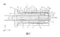
本發明之其他的特徵及功效,將於參照圖式的實施方式中清楚地呈現,其中:圖1是本發明電連接器的一第一實施例的一立體圖;圖2是該第一實施例的一立體分解圖;圖3是該第一實施例的另一立體分解圖,說明該第一實施例的載板、彈性壓片與柔性電路板組裝於殼體的方式,圖中該殼體剖去了位於柔性電路板組裝槽上方的局部部分;圖4是該第一實施例的一剖視圖;圖5是該第一實施例的另一剖視圖;圖6是本發明電連接器的一第二實施例的一立體圖;圖7是該第二實施例的一立體分解圖;圖8是該第二實施例的一剖視圖;以及圖9是該第二實施例的一立體圖,圖中柔性電路板插入預先組裝有載板、彈性壓片的殼體。Other features and effects of the present invention will be clearly presented in the embodiment with reference to the drawings, in which: FIG. 1 is a perspective view of a first embodiment of the electrical connector of the present invention; FIG. 2 is the first embodiment Figure 3 is another perspective exploded view of the first embodiment, illustrating the manner in which the carrier board, the elastic pressing sheet, and the flexible circuit board of the first embodiment are assembled in the housing, the housing in the figure A partial section above the assembly slot of the flexible circuit board is cut away; FIG. 4 is a cross-sectional view of the first embodiment; FIG. 5 is another cross-sectional view of the first embodiment;6 is a perspective view of a second embodiment of the electrical connector of the present invention; FIG. 7 is a perspective exploded view of the second embodiment; FIG. 8 is a cross-sectional view of the second embodiment; and FIG. 9 is the first embodiment A perspective view of the second embodiment, in which the flexible circuit board is inserted into a housing pre-assembled with a carrier board and elastic pressing sheets.
在本發明被詳細描述之前,應當注意在以下的說明內容中,類似的元件是以相同的編號來表示。Before the present invention is described in detail, it should be noted that in the following description, similar elements are denoted by the same numbers.
參閱圖1至圖2,本發明電連接器100之一第一實施例,包含一殼體1、兩載板2、兩彈性壓片3,以及兩柔性電路板4。Referring to FIGS. 1 to 2, a first embodiment of the
參閱圖1至圖4,該殼體1具有沿一前後方向D1(箭頭所指的方向為前,反向為後)排列的前端及後端,且具有由殼體1的後端朝前形成並沿一上下方向D2(箭頭所指的方向為上,反向為下)排列的兩個柔性電路板組裝槽11,以及位於該兩柔性電路板組裝槽11之間且分別面對該兩柔性電路板組裝槽11的上下兩排對接端子用插槽12,每排對接端子用插槽12的該等對接端子用插槽12沿一左右方向D3(箭頭所指的方向為右,反向為左)並排。每一對接端子用插槽12具有連通於對應的柔性電路板組裝槽11柔性電路板組裝槽的一開口121,以及位於該殼體1前端的一對接端子用插孔122。需要說明的是,所述柔性電路板組裝槽11的數量與所述對接端子用插槽12的排數對應於所述載板2、所述彈性壓片3與所述柔性電路板4的數量,所述數量各為兩個,因此,雖然在本第一實施例中所述柔性電路板組裝槽11的數量與所述對接端子用插槽12的排數各為兩個。但在其他實施態樣中,當所述載板2、所述彈性壓片3與所述柔性電路板4的數量調整成各為一個以上或為三個以上時,所述柔性電路板組裝槽11的數量與所述對接端子用插槽12的排數也可以對應調整成各為一個,或為三個以上。1 to 4, the
參閱圖2至圖5,該兩載板2用於分別插入並組裝於該兩柔性電路板組裝槽11。每一柔性電路板組裝槽11具有位於後方且供對應的載板2插入的一後插口111、形成於兩側內壁面且由後朝前延伸以容置該兩載板2的左右兩側緣的兩個導引軌道112,以及分別形成於位於兩側內壁面的該兩導引軌道112內的兩個扣持凹部113。在本第一實施例中,該兩扣持凹部113為穿孔形式,但在其他實施態樣中,該兩扣持凹部113也可以為盲孔形式。每一載板2具有朝向對應的該排對接端子用插槽12的一第一面21、相反於該第一面21的一第二面22,以及形成於左右兩側緣且用以對應扣接於該兩扣持凹部113的兩個彈性扣持凸部23,在本第一實施例中,所述彈性扣持凸部23構造在彈性臂28上,而所述彈性臂28是構造於貫穿該載板2的長條狀貫孔29的外側。Referring to FIGS. 2 to 5, the two
該兩彈性壓片3分別組裝於該兩載板2的第二面22,該彈性壓片3一體地具有一基部31,以及自該基部31的前緣一體延伸形成且沿該左右方向D3並排以對應該等對接端子用插槽12的多個彈性指部32。該基部31具有多個固定孔311,該載板2還具有形成於第二面22穿設固定於該等固定孔311的多個固定柱24,在本第一實施例中,該等固定柱24與該等固定孔311是通過熱熔固定的方式互相結合,但在其他實施態樣中也可以是透過鉚接等其他方式互相結合。該兩柔性電路板4分別組裝於該兩載板2的第一面21且通過該兩載板2組裝於該兩柔性電路板組裝槽11內,其中,每一彈性壓片3的該等彈性指部32分別朝向對應的該等對接端子用插槽12的方向施壓於對應的柔性電路板4。通過該載板2將該柔性電路板4組裝至殼體1內,且通過該彈性壓片3的彈性指部32施壓於該柔性電路板4,能在一對接連接器200的對接端子201(見圖5)自該殼體1的該等對接端子用插孔122插入該等對接端子用插槽12後,提供該柔性電路板4的接觸指部(圖未示)與該對接連接器200的對接端子201之間的穩定的正向接觸力,以使該柔性電路板4的接觸指部(圖未示)與該對接連接器200的對接端子201通過該等對接端子用插槽12的開口121穩定地接觸,避免連接斷路或是接觸不良的問題,且同時簡化及模組化整體的組裝構造。The two elastic
該柔性電路板4具有組裝於該載板2的第一面21的一裝載部41、連接於該裝載部41且繞過該載板2的前端的一定位部42,以及連接於該定位部42且朝向該載板2的第二面22翻摺的一翻摺部43。該殼體1的每一柔性電路板組裝槽11還具有形成於前端處的內壁面的多個定位孔114。該柔性電路板4的定位部42形成有分別對應於該等定位孔114的多個定位穿孔44。該載板2還具有形成於前端且用以穿過該等定位穿孔44以插設於該等定位孔114的多個定位柱25,藉此使該柔性電路板4得到定位,且將該等柔性電路板4與該等載板2一同穩定地固定於該等柔性電路板組裝槽11內。在本第一實施例中,該等定位孔114為盲孔形式,但在其他實施態樣中,該等定位孔114也可以為穿孔形式。The
需要說明的是,由於該兩對接端子用插槽12是位於組裝有該兩載板2的該殼體1的柔性電路板組裝槽11之間,因此上方的載板2的第一面21是朝向下方,而下方的載板2的第一面21是朝向上方,也就是說,兩個載板是以不同的面向設置於該殼體1的柔性電路板組裝槽11,然而在其他實施態樣中,所述對接端子用插槽12對於組裝有載板2的柔性電路板組裝槽11的相對位置可以依照需求調整,舉例來說,位於下方的對接端子用插槽12也可以調整至組裝有下方柔性電路板組裝槽11的下方,此時下方的載板2的第一面21將朝向下方,且彈性壓片3與柔性電路板4的設置方式也將隨之對應調整。It should be noted that since the two
另外,在本第一實施例中,每一載板2還具有分別對應該等彈性指部32且上下地貫穿的多個穿槽26,該等彈性指部32分別穿過該等穿槽26以朝向該等對接端子用插槽12的方向施壓於該柔性電路板4。此外,每一載板2的第一面21的後側緣處還形成有朝遠離該第二面22的方向延伸出的一握持部27,該殼體1的後端上下側處還形成有分別且連通該兩柔性電路板組裝槽11且對應容置該兩載板2的握持部27的兩個容置凹部13,所述握持部27能於組裝時供組裝者握持操作,藉此方便組裝作業。In addition, in the first embodiment, each
參閱圖1及圖4,在本第一實施例中,該電連接器100的殼體1適用於插置地裝設在一面板(圖未示)的一安裝孔(圖未示)。該殼體1還具有位於後端且分別朝該左右兩側凸出的兩靠抵部15,以及位於右側的靠抵部15前方且自該殼體1的前端朝後延伸且末端部朝右凸出的一彈扣條16。當該殼體1朝前地插入該面板的安裝孔時,該彈扣條16被該面板壓下後,越過該面板並靠抵於該面板的安裝孔右側的前側面部分,而該兩靠抵部15則靠抵於該面板的安裝孔左右兩側的後側面部分。換句話說,此時該兩靠抵部15與該彈扣條16共同夾持該面板,以使該電連接器100的殼體1裝設於該面板的安裝孔。另外,位於右側的靠抵部15形成有一穿孔151,該殼體還具有連接於該彈扣條16且朝後延伸地穿過該穿孔151的一操作桿17,當該電連接器100的殼體1裝設於該面板的安裝孔時,使用者可以朝左撥動該操作桿17以連動該彈扣條16被壓下,即可將該電連接器100的殼體1朝後退出該面板的安裝孔以解除安裝。1 and 4, in the first embodiment, the
參閱圖6至圖9,本發明電連接器100之一第二實施例與該第一實施例不同之處在於,每一柔性電路板組裝槽11的每一個導引軌道112內具有形成於內壁面且用以與對應的載板2的彈性扣持凸部23對應扣接的後扣持凹部116及前扣持凹部115。該殼體1具有形成於頂部與底部且分別連通於該兩柔性電路板組裝槽11以朝向該兩載板2的第二面22的兩個開窗14。如圖9所示,當該兩載板2的彈性扣持凸部23扣接於位於後方的所述後扣持凹部116,所述載板2並未完全插入對應的柔性電路板組裝槽11,且所述載板2的前端自對應的開窗14顯露出。此時,該柔性電路板4能自所述後插口111伸入該柔性電路板組裝槽11以設於該載板2的第一面21,且該柔性電路板4的翻摺部43自所述開窗14穿出該殼體1,這時組裝者能通過所述開窗14調整所述柔性電路板4的位置,以使所述載板2的定位柱25對準並穿伸於所述柔性電路板4的定位穿孔44。如圖6所示,接著,將該兩載板2繼續朝前推,使所述載板2的彈性扣持凸部23扣接於位於前方的所述前扣持凹部115,此時,所述載板2的定位柱25穿過所述定位穿孔44且插設於所述定位孔114,且該柔性電路板4的翻摺部43被壓入柔性電路板組裝槽11內,如此即完成組裝步驟。藉由該殼體1的後扣持凹部116與前扣持凹部115能構成兩段式組裝構造,組裝有該彈性壓片3的該載板2能藉由所述兩段式組裝構造預先組裝於該殼體1上,而該柔性電路板4能夠之後再插入至該殼體1並藉由該載板2組裝到該殼體1內,藉此使該電連接器100的製造組裝流程能針對各種情況有不同的應用。例如,針對不同的客戶能夠提供預先組裝好的半成品,以供客戶自行組裝尚未組裝的柔性電路板4部分,另外,藉由預先組裝好的半成品也能使在各製程間的運輸作業更為便利。6-9, the second embodiment of the
另外,在本第二實施例中,構造有所述彈性扣持凸部23的彈性臂28是直接自該載板2的左右兩側朝前延伸出。In addition, in the second embodiment, the
綜上所述,本發明通過該載板2將該柔性電路板4組裝至殼體1內,且通過該彈性壓片3的彈性指部32施壓於該柔性電路板4,提供該柔性電路板4與對接連接器200的對接端子201之間的穩定的正向接觸力,避免連接斷路或是接觸不良的問題,且同時簡化及模組化整體的組裝構造。在一些實施態樣中,該殼體1的後扣持凹部116與前扣持凹部115能構成兩段式組裝構造,組裝有該彈性壓片3的該載板2能藉由所述兩段式組裝構造預先組裝於該殼體1上,而該柔性電路板4能夠之後再插入至該殼體1並藉由該載板2組裝到該殼體1內,藉此使該電連接器100的製造組裝流程能針對各種情況有不同的應用。In summary, the present invention assembles the
惟以上所述者,僅為本發明之實施例而已,當不能以此限定本發明實施之範圍,凡是依本發明申請專利範圍及專利說明書內容所作之簡單的等效變化與修飾,皆仍屬本發明專利涵蓋之範圍內。However, the above are only examples of the present invention, and the present invention cannot be limited by this.It is clear that the scope of implementation, all simple equivalent changes and modifications made in accordance with the scope of the patent application of the present invention and the content of the patent specification are still within the scope of the patent of the present invention.
100:電連接器100: electrical connector
1:殼體1: shell
11:柔性電路板組裝槽11: Flexible circuit board assembly slot
111:後插口111: Rear socket
112:導引軌道112: Guidance Track
113:扣持凹部113: Buckle recess
114:定位孔114: positioning hole
12:對接端子用插槽12: Slot for docking terminal
121:開口121: open
122:對接端子用插孔122: Jack for docking terminal
13:容置凹部13: accommodating recess
15:靠抵部15: Leaning Department
151:穿孔151: Piercing
17:操作桿17: Joystick
2:載板2: carrier board
21:第一面21: First side
22:第二面22: second side
23:彈性扣持凸部23: Elastic buckle convex part
24:固定柱24: fixed column
25:定位柱25: positioning column
27:握持部27: Grip
28:彈性臂28: Flexible arm
29:長條狀貫孔29: Long strip through hole
3:彈性壓片3: Elastic tablet
31:基部31: Base
311:固定孔311: fixed hole
32:彈性指部32: Elastic fingers
4:柔性電路板4: Flexible circuit board
41:裝載部41: Loading Department
42:定位部42: Positioning part
43:翻摺部43: Folding part
D1:前後方向D1: front and rear direction
D2:上下方向D2: Up and down direction
D3:左右方向D3: Left and right direction
Claims (7)
Translated fromChineseApplications Claiming Priority (2)
| Application Number | Priority Date | Filing Date | Title |
|---|---|---|---|
| CN202010646328.6 | 2020-07-07 | ||
| CN202010646328.6ACN113922115B (en) | 2020-07-07 | 2020-07-07 | Electric connector |
Publications (2)
| Publication Number | Publication Date |
|---|---|
| TWI736424Btrue TWI736424B (en) | 2021-08-11 |
| TW202203512A TW202203512A (en) | 2022-01-16 |
Family
ID=78283182
Family Applications (1)
| Application Number | Title | Priority Date | Filing Date |
|---|---|---|---|
| TW109132364ATWI736424B (en) | 2020-07-07 | 2020-09-18 | Electrical connector |
Country Status (2)
| Country | Link |
|---|---|
| CN (1) | CN113922115B (en) |
| TW (1) | TWI736424B (en) |
Citations (4)
| Publication number | Priority date | Publication date | Assignee | Title |
|---|---|---|---|---|
| US5057037A (en)* | 1990-02-23 | 1991-10-15 | E. I. Du Pont De Nemours And Company | Connector |
| CN2490713Y (en)* | 2001-05-31 | 2002-05-08 | 蔡周旋 | Flexible PCB Connector |
| CN105900288A (en)* | 2014-01-09 | 2016-08-24 | 松下知识产权经营株式会社 | Cable holding member, plug connector, connector device, flat cable, and method of assembling the plug connector |
| TWM595901U (en)* | 2020-03-03 | 2020-05-21 | 正崴精密工業股份有限公司 | Electrical connector |
Family Cites Families (3)
| Publication number | Priority date | Publication date | Assignee | Title |
|---|---|---|---|---|
| CN2519441Y (en)* | 2001-11-21 | 2002-10-30 | 富士康(昆山)电脑接插件有限公司 | Electric connector |
| JP4514802B2 (en)* | 2008-02-05 | 2010-07-28 | ヒロセ電機株式会社 | Flat conductor electrical connector |
| CN203967291U (en)* | 2014-07-14 | 2014-11-26 | 东莞杰思实业有限公司 | A kind of card connector |
- 2020
- 2020-07-07CNCN202010646328.6Apatent/CN113922115B/enactiveActive
- 2020-09-18TWTW109132364Apatent/TWI736424B/enactive
Patent Citations (4)
| Publication number | Priority date | Publication date | Assignee | Title |
|---|---|---|---|---|
| US5057037A (en)* | 1990-02-23 | 1991-10-15 | E. I. Du Pont De Nemours And Company | Connector |
| CN2490713Y (en)* | 2001-05-31 | 2002-05-08 | 蔡周旋 | Flexible PCB Connector |
| CN105900288A (en)* | 2014-01-09 | 2016-08-24 | 松下知识产权经营株式会社 | Cable holding member, plug connector, connector device, flat cable, and method of assembling the plug connector |
| TWM595901U (en)* | 2020-03-03 | 2020-05-21 | 正崴精密工業股份有限公司 | Electrical connector |
Also Published As
| Publication number | Publication date |
|---|---|
| CN113922115A (en) | 2022-01-11 |
| TW202203512A (en) | 2022-01-16 |
| CN113922115B (en) | 2024-03-08 |
Similar Documents
| Publication | Publication Date | Title |
|---|---|---|
| CN110165428B (en) | Puncture type electric connector | |
| JPH02183977A (en) | Electric connector | |
| CN106848658A (en) | Electric connector | |
| JP4291345B2 (en) | Connected device | |
| CN110061375A (en) | Connector, docking connector and connector assembly | |
| CN216145850U (en) | Clip line connector | |
| JPH07282916A (en) | Connector for flat cable | |
| JP6210543B2 (en) | Terminal connection device | |
| CN201576784U (en) | Electric connector | |
| JP2001043918A (en) | Electric connector | |
| CN114389108A (en) | Electrical connectors with flat conductors | |
| JP2004335221A (en) | ID connector | |
| TWI736424B (en) | Electrical connector | |
| US6371772B1 (en) | Electrical connector with enhanced contacts | |
| CN219610784U (en) | Self-locking FPC connector | |
| TWI832606B (en) | Connector components | |
| TWI764625B (en) | Electrical connector | |
| CN201041894Y (en) | electrical connector | |
| TWI704732B (en) | Base of electrical connector and electrical connector thereof | |
| JP3358357B2 (en) | Board connector | |
| CN116565608A (en) | Terminal locking piece, terminal and connector | |
| TWI774958B (en) | Trunk connector | |
| CN201478578U (en) | Electric connector with metal casing | |
| CN222601573U (en) | DisplayPort plug connector | |
| KR101001881B1 (en) | Assembly structure of circuit board and board mounted connector |