TWI735826B - Backlight module - Google Patents
Backlight moduleDownload PDFInfo
- Publication number
- TWI735826B TWI735826BTW107144240ATW107144240ATWI735826BTW I735826 BTWI735826 BTW I735826BTW 107144240 ATW107144240 ATW 107144240ATW 107144240 ATW107144240 ATW 107144240ATW I735826 BTWI735826 BTW I735826B
- Authority
- TW
- Taiwan
- Prior art keywords
- unit
- area
- reflective
- areas
- backlight module
- Prior art date
Links
- 239000003086colorantSubstances0.000claimsabstractdescription7
- 230000005540biological transmissionEffects0.000claimsdescription38
- 239000000463materialSubstances0.000claimsdescription12
- 239000011159matrix materialSubstances0.000claimsdescription12
- 239000000758substrateSubstances0.000claimsdescription6
- 230000007423decreaseEffects0.000claimsdescription4
- 238000010586diagramMethods0.000description9
- 239000004973liquid crystal related substanceSubstances0.000description4
- 230000000694effectsEffects0.000description3
- 238000005282brighteningMethods0.000description2
- 238000005265energy consumptionMethods0.000description1
- 230000001788irregularEffects0.000description1
- 230000003287optical effectEffects0.000description1
- 230000002093peripheral effectEffects0.000description1
Images


Classifications
- G—PHYSICS
- G02—OPTICS
- G02F—OPTICAL DEVICES OR ARRANGEMENTS FOR THE CONTROL OF LIGHT BY MODIFICATION OF THE OPTICAL PROPERTIES OF THE MEDIA OF THE ELEMENTS INVOLVED THEREIN; NON-LINEAR OPTICS; FREQUENCY-CHANGING OF LIGHT; OPTICAL LOGIC ELEMENTS; OPTICAL ANALOGUE/DIGITAL CONVERTERS
- G02F1/00—Devices or arrangements for the control of the intensity, colour, phase, polarisation or direction of light arriving from an independent light source, e.g. switching, gating or modulating; Non-linear optics
- G02F1/01—Devices or arrangements for the control of the intensity, colour, phase, polarisation or direction of light arriving from an independent light source, e.g. switching, gating or modulating; Non-linear optics for the control of the intensity, phase, polarisation or colour
- G02F1/13—Devices or arrangements for the control of the intensity, colour, phase, polarisation or direction of light arriving from an independent light source, e.g. switching, gating or modulating; Non-linear optics for the control of the intensity, phase, polarisation or colour based on liquid crystals, e.g. single liquid crystal display cells
- G02F1/133—Constructional arrangements; Operation of liquid crystal cells; Circuit arrangements
- G02F1/1333—Constructional arrangements; Manufacturing methods
- G02F1/1335—Structural association of cells with optical devices, e.g. polarisers or reflectors
- G02F1/1336—Illuminating devices
- G02F1/133602—Direct backlight
- G02F1/133611—Direct backlight including means for improving the brightness uniformity
- G—PHYSICS
- G02—OPTICS
- G02F—OPTICAL DEVICES OR ARRANGEMENTS FOR THE CONTROL OF LIGHT BY MODIFICATION OF THE OPTICAL PROPERTIES OF THE MEDIA OF THE ELEMENTS INVOLVED THEREIN; NON-LINEAR OPTICS; FREQUENCY-CHANGING OF LIGHT; OPTICAL LOGIC ELEMENTS; OPTICAL ANALOGUE/DIGITAL CONVERTERS
- G02F1/00—Devices or arrangements for the control of the intensity, colour, phase, polarisation or direction of light arriving from an independent light source, e.g. switching, gating or modulating; Non-linear optics
- G02F1/01—Devices or arrangements for the control of the intensity, colour, phase, polarisation or direction of light arriving from an independent light source, e.g. switching, gating or modulating; Non-linear optics for the control of the intensity, phase, polarisation or colour
- G02F1/13—Devices or arrangements for the control of the intensity, colour, phase, polarisation or direction of light arriving from an independent light source, e.g. switching, gating or modulating; Non-linear optics for the control of the intensity, phase, polarisation or colour based on liquid crystals, e.g. single liquid crystal display cells
- G02F1/133—Constructional arrangements; Operation of liquid crystal cells; Circuit arrangements
- G02F1/1333—Constructional arrangements; Manufacturing methods
- G02F1/133308—Support structures for LCD panels, e.g. frames or bezels
- G—PHYSICS
- G02—OPTICS
- G02F—OPTICAL DEVICES OR ARRANGEMENTS FOR THE CONTROL OF LIGHT BY MODIFICATION OF THE OPTICAL PROPERTIES OF THE MEDIA OF THE ELEMENTS INVOLVED THEREIN; NON-LINEAR OPTICS; FREQUENCY-CHANGING OF LIGHT; OPTICAL LOGIC ELEMENTS; OPTICAL ANALOGUE/DIGITAL CONVERTERS
- G02F1/00—Devices or arrangements for the control of the intensity, colour, phase, polarisation or direction of light arriving from an independent light source, e.g. switching, gating or modulating; Non-linear optics
- G02F1/01—Devices or arrangements for the control of the intensity, colour, phase, polarisation or direction of light arriving from an independent light source, e.g. switching, gating or modulating; Non-linear optics for the control of the intensity, phase, polarisation or colour
- G02F1/13—Devices or arrangements for the control of the intensity, colour, phase, polarisation or direction of light arriving from an independent light source, e.g. switching, gating or modulating; Non-linear optics for the control of the intensity, phase, polarisation or colour based on liquid crystals, e.g. single liquid crystal display cells
- G02F1/133—Constructional arrangements; Operation of liquid crystal cells; Circuit arrangements
- G02F1/1333—Constructional arrangements; Manufacturing methods
- G02F1/1335—Structural association of cells with optical devices, e.g. polarisers or reflectors
- G02F1/1336—Illuminating devices
- G02F1/133602—Direct backlight
- G02F1/133603—Direct backlight with LEDs
- G—PHYSICS
- G02—OPTICS
- G02F—OPTICAL DEVICES OR ARRANGEMENTS FOR THE CONTROL OF LIGHT BY MODIFICATION OF THE OPTICAL PROPERTIES OF THE MEDIA OF THE ELEMENTS INVOLVED THEREIN; NON-LINEAR OPTICS; FREQUENCY-CHANGING OF LIGHT; OPTICAL LOGIC ELEMENTS; OPTICAL ANALOGUE/DIGITAL CONVERTERS
- G02F1/00—Devices or arrangements for the control of the intensity, colour, phase, polarisation or direction of light arriving from an independent light source, e.g. switching, gating or modulating; Non-linear optics
- G02F1/01—Devices or arrangements for the control of the intensity, colour, phase, polarisation or direction of light arriving from an independent light source, e.g. switching, gating or modulating; Non-linear optics for the control of the intensity, phase, polarisation or colour
- G02F1/13—Devices or arrangements for the control of the intensity, colour, phase, polarisation or direction of light arriving from an independent light source, e.g. switching, gating or modulating; Non-linear optics for the control of the intensity, phase, polarisation or colour based on liquid crystals, e.g. single liquid crystal display cells
- G02F1/133—Constructional arrangements; Operation of liquid crystal cells; Circuit arrangements
- G02F1/1333—Constructional arrangements; Manufacturing methods
- G02F1/1335—Structural association of cells with optical devices, e.g. polarisers or reflectors
- G02F1/1336—Illuminating devices
- G02F1/133602—Direct backlight
- G02F1/133605—Direct backlight including specially adapted reflectors
- G—PHYSICS
- G02—OPTICS
- G02F—OPTICAL DEVICES OR ARRANGEMENTS FOR THE CONTROL OF LIGHT BY MODIFICATION OF THE OPTICAL PROPERTIES OF THE MEDIA OF THE ELEMENTS INVOLVED THEREIN; NON-LINEAR OPTICS; FREQUENCY-CHANGING OF LIGHT; OPTICAL LOGIC ELEMENTS; OPTICAL ANALOGUE/DIGITAL CONVERTERS
- G02F1/00—Devices or arrangements for the control of the intensity, colour, phase, polarisation or direction of light arriving from an independent light source, e.g. switching, gating or modulating; Non-linear optics
- G02F1/01—Devices or arrangements for the control of the intensity, colour, phase, polarisation or direction of light arriving from an independent light source, e.g. switching, gating or modulating; Non-linear optics for the control of the intensity, phase, polarisation or colour
- G02F1/13—Devices or arrangements for the control of the intensity, colour, phase, polarisation or direction of light arriving from an independent light source, e.g. switching, gating or modulating; Non-linear optics for the control of the intensity, phase, polarisation or colour based on liquid crystals, e.g. single liquid crystal display cells
- G02F1/133—Constructional arrangements; Operation of liquid crystal cells; Circuit arrangements
- G02F1/1333—Constructional arrangements; Manufacturing methods
- G02F1/1335—Structural association of cells with optical devices, e.g. polarisers or reflectors
- G02F1/1336—Illuminating devices
- G02F1/133602—Direct backlight
- G02F1/133606—Direct backlight including a specially adapted diffusing, scattering or light controlling members
- G—PHYSICS
- G02—OPTICS
- G02F—OPTICAL DEVICES OR ARRANGEMENTS FOR THE CONTROL OF LIGHT BY MODIFICATION OF THE OPTICAL PROPERTIES OF THE MEDIA OF THE ELEMENTS INVOLVED THEREIN; NON-LINEAR OPTICS; FREQUENCY-CHANGING OF LIGHT; OPTICAL LOGIC ELEMENTS; OPTICAL ANALOGUE/DIGITAL CONVERTERS
- G02F1/00—Devices or arrangements for the control of the intensity, colour, phase, polarisation or direction of light arriving from an independent light source, e.g. switching, gating or modulating; Non-linear optics
- G02F1/01—Devices or arrangements for the control of the intensity, colour, phase, polarisation or direction of light arriving from an independent light source, e.g. switching, gating or modulating; Non-linear optics for the control of the intensity, phase, polarisation or colour
- G02F1/13—Devices or arrangements for the control of the intensity, colour, phase, polarisation or direction of light arriving from an independent light source, e.g. switching, gating or modulating; Non-linear optics for the control of the intensity, phase, polarisation or colour based on liquid crystals, e.g. single liquid crystal display cells
- G02F1/133—Constructional arrangements; Operation of liquid crystal cells; Circuit arrangements
- G02F1/1333—Constructional arrangements; Manufacturing methods
- G02F1/1335—Structural association of cells with optical devices, e.g. polarisers or reflectors
- G02F1/1336—Illuminating devices
- G02F1/133602—Direct backlight
- G02F1/133609—Direct backlight including means for improving the color mixing, e.g. white
- G—PHYSICS
- G02—OPTICS
- G02F—OPTICAL DEVICES OR ARRANGEMENTS FOR THE CONTROL OF LIGHT BY MODIFICATION OF THE OPTICAL PROPERTIES OF THE MEDIA OF THE ELEMENTS INVOLVED THEREIN; NON-LINEAR OPTICS; FREQUENCY-CHANGING OF LIGHT; OPTICAL LOGIC ELEMENTS; OPTICAL ANALOGUE/DIGITAL CONVERTERS
- G02F1/00—Devices or arrangements for the control of the intensity, colour, phase, polarisation or direction of light arriving from an independent light source, e.g. switching, gating or modulating; Non-linear optics
- G02F1/01—Devices or arrangements for the control of the intensity, colour, phase, polarisation or direction of light arriving from an independent light source, e.g. switching, gating or modulating; Non-linear optics for the control of the intensity, phase, polarisation or colour
- G02F1/13—Devices or arrangements for the control of the intensity, colour, phase, polarisation or direction of light arriving from an independent light source, e.g. switching, gating or modulating; Non-linear optics for the control of the intensity, phase, polarisation or colour based on liquid crystals, e.g. single liquid crystal display cells
- G02F1/133—Constructional arrangements; Operation of liquid crystal cells; Circuit arrangements
- G02F1/1333—Constructional arrangements; Manufacturing methods
- G02F1/133308—Support structures for LCD panels, e.g. frames or bezels
- G02F1/133314—Back frames
- G—PHYSICS
- G02—OPTICS
- G02F—OPTICAL DEVICES OR ARRANGEMENTS FOR THE CONTROL OF LIGHT BY MODIFICATION OF THE OPTICAL PROPERTIES OF THE MEDIA OF THE ELEMENTS INVOLVED THEREIN; NON-LINEAR OPTICS; FREQUENCY-CHANGING OF LIGHT; OPTICAL LOGIC ELEMENTS; OPTICAL ANALOGUE/DIGITAL CONVERTERS
- G02F1/00—Devices or arrangements for the control of the intensity, colour, phase, polarisation or direction of light arriving from an independent light source, e.g. switching, gating or modulating; Non-linear optics
- G02F1/01—Devices or arrangements for the control of the intensity, colour, phase, polarisation or direction of light arriving from an independent light source, e.g. switching, gating or modulating; Non-linear optics for the control of the intensity, phase, polarisation or colour
- G02F1/13—Devices or arrangements for the control of the intensity, colour, phase, polarisation or direction of light arriving from an independent light source, e.g. switching, gating or modulating; Non-linear optics for the control of the intensity, phase, polarisation or colour based on liquid crystals, e.g. single liquid crystal display cells
- G02F1/133—Constructional arrangements; Operation of liquid crystal cells; Circuit arrangements
- G02F1/1333—Constructional arrangements; Manufacturing methods
- G02F1/1335—Structural association of cells with optical devices, e.g. polarisers or reflectors
- G02F1/1336—Illuminating devices
- G02F1/133614—Illuminating devices using photoluminescence, e.g. phosphors illuminated by UV or blue light
Landscapes
- Physics & Mathematics (AREA)
- Nonlinear Science (AREA)
- Mathematical Physics (AREA)
- Chemical & Material Sciences (AREA)
- Crystallography & Structural Chemistry (AREA)
- General Physics & Mathematics (AREA)
- Optics & Photonics (AREA)
- Planar Illumination Modules (AREA)
Abstract
Description
Translated fromChinese本發明涉及一種背光模組。The invention relates to a backlight module.
液晶顯示器是一種依靠背光模組發光、在液晶顯示面板上顯示圖像的一種顯示器(背光源的光線經過液晶折射及濾光結構濾光之後呈現不同顏色)。隨著液晶顯示器朝向薄型化方向發展,背光模組的設計也力求更加輕薄。習知的一種直下式背光模組包括:背板、設置在背板上的反射片、設置在反射片上的複數發光二極管(light emitting diode,LED)燈、設置在複數LED燈上方的擴散片及設置在擴散片遠離背板一側的增亮膜,其中LED燈作為光源,藉由由反射片與擴散片間隔設置形成的背光腔混光,再經過擴散板和增亮膜的均勻化,將LED燈的類似點光源調整為面光源。降低背光模組的厚度,通常藉由降低背板與擴散片之間的距離(混光距離)來實現,然而這需要增加設置在背板上LED燈的密度才能保證背光模組達到均勻的出光效果,由此又將導致背光模組能耗的增加。The liquid crystal display is a kind of display that relies on the backlight module to emit light and display images on the liquid crystal display panel (the light from the backlight source is filtered by the liquid crystal refraction and filter structure to show different colors). With the development of liquid crystal displays in the direction of thinning, the design of the backlight module also strives to be thinner and lighter. A conventional direct-lit backlight module includes: a back plate, a reflector sheet arranged on the back plate, a plurality of light emitting diode (LED) lamps arranged on the reflector sheet, a diffuser sheet arranged above the plurality of LED lamps, and The brightness enhancement film arranged on the side of the diffuser away from the backplane, where the LED lamp is used as the light source, and the backlight cavity formed by the reflective sheet and the diffuser is arranged at intervals to mix light, and then the diffuser and the brightness enhancement film are homogenized. The similar point light source of the LED lamp is adjusted to a surface light source. Reducing the thickness of the backlight module is usually achieved by reducing the distance between the backplane and the diffuser (light mixing distance). However, this requires increasing the density of the LED lights on the backplane to ensure that the backlight module achieves uniform light output. Effect, which in turn will lead to an increase in the energy consumption of the backlight module.
有鑑於此,有必要提供一種背光模組,其可在不增加背板上LED燈的密度的情況下,仍能保證背光模組達到均勻的出光效果。In view of this, it is necessary to provide a backlight module, which can still ensure that the backlight module achieves a uniform light output effect without increasing the density of the LED lights on the backplane.
一種背光模組,其包括複數背光單元,每一個背光單元包括:背板單元;第一反射片單元,設置在所述背板單元上;一組LED燈,設置在所述背板單元上且穿過所述第一反射片單元,包括發不同顏色光的至少兩個LED燈;以及設置在所述一組LED燈和所述第一反射片單元遠離所述背板單元一側的導光基體單元,所述導光基體單元為透光材質;每一個背光單元還包括設置在所述導光基體單元遠離LED燈一側上的第二反射片單元,所述第二反射片單元包括複數反射區和複數透射區。A backlight module includes a plurality of backlight units, and each backlight unit includes:A backplane unit; a first reflector unit, arranged on the backplane unit; a group of LED lights, arranged on the backplane unit and passing through the first reflector unit, including at least one that emits light of different colors Two LED lights; and a light guide base unit disposed on the side of the set of LED lights and the first reflector unit away from the back plate unit, the light guide base unit is made of light-transmitting material; each backlight The unit further includes a second reflective sheet unit arranged on a side of the light guide base unit away from the LED lamp, and the second reflective sheet unit includes a plurality of reflective areas and a plurality of transmissive areas.
一種背光模組,包括:背板;第一反射片,設置在所述背板上;複數LED燈,設置在所述背板上且穿過所述第一反射片,所述複數LED燈包括發不同顏色光的至少兩種LED燈;以及設置在所述複數LED燈和所述第一反射片遠離所述背板一側的導光基體,所述導光基體單元為透光材質;所述背光模組還包括設置在所述導光基體遠離所述複數LED燈一側上的第二反射片,所述第二反射片包括複數第二反射片單元,每一個第二反射片單元包括複數反射區和複數透射區。A backlight module includes: a back plate; a first reflecting sheet arranged on the back plate; a plurality of LED lights arranged on the back plate and passing through the first reflecting sheet, the plurality of LED lights including At least two kinds of LED lights emitting light of different colors; and a light guide base disposed on the side of the plurality of LED lights and the first reflector away from the back plate, and the light guide base unit is made of light-transmitting material; The backlight module further includes a second reflective sheet disposed on a side of the light guide base away from the plurality of LED lamps, the second reflective sheet includes a plurality of second reflective sheet units, and each second reflective sheet unit includes Complex reflection area and complex transmission area.
本發明藉由在背光模組的背光單元中引入特定設計的第二反射片單元,使LED燈發出的光線在第一反射片單元和第二反射片單元之間經歷多次反射,使來自LED燈的光線穿過第二反射片單元後既能保證光線的強度又使出光均勻,可降低背光模組的厚度(混光距離),而不需要增加LED燈的排佈密度。In the present invention, by introducing a specially designed second reflective sheet unit into the backlight unit of the backlight module, the light emitted by the LED lamp undergoes multiple reflections between the first reflective sheet unit and the second reflective sheet unit, so that the light from the LED After the light of the lamp passes through the second reflecting sheet unit, the intensity of the light can be ensured and the light can be uniformly emitted, and the thickness (light mixing distance) of the backlight module can be reduced without increasing the arrangement density of the LED lamps.
100:背光模組100: Backlight module
10:背光單元10: Backlight unit
11:背板單元11: Backplane unit
110:背板110: Backplane
13:LED燈13: LED lights
12:第一反射片單元12: The first reflector unit
120:第一反射片120: The first reflector
14:導光基體單元14: Light guide base unit
140:導光基體140: Light guide substrate
121:貫穿孔121: Through hole
20:第二反射片單元20: The second reflector unit
30:第二反射片30: second reflector
15:擴散板單元15: diffuser unit
150:擴散板150: diffuser
17:增亮膜單元17: Brightness enhancement film unit
170:增亮膜170: Brightening film
21、211、212、213、214、215:反射區21, 211, 212, 213, 214, 215: reflection area
23、231、232、235:透射區23, 231, 232, 235: transmission area
D:直徑方向D: Diameter direction
圖1為本發明實施例的背光模組剖面示意圖。FIG. 1 is a schematic cross-sectional view of a backlight module according to an embodiment of the present invention.
圖2為本發明一實施例的第二反射片單元的平面示意圖。2 is a schematic plan view of a second reflector unit according to an embodiment of the invention.
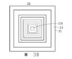
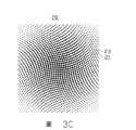
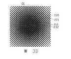
圖3A-圖3D為複數變更施例的第二反射片單元的平面示意圖。3A to 3D are schematic plan views of the second reflective sheet unit according to a plurality of modified embodiments.
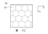
圖4A-圖4C為第二反射片的第二反射片單元的幾種排佈示意圖。4A-4C are schematic diagrams of several arrangements of the second reflective sheet unit of the second reflective sheet.
圖5為第二反射片單元、第一反射片單元及LED燈的對應關係示意圖。FIG. 5 is a schematic diagram of the corresponding relationship between the second reflective sheet unit, the first reflective sheet unit and the LED lamp.
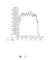
圖6為使用圖4A的第二反射片的背光模組的出光強度示意圖。6 is a schematic diagram of the light output intensity of the backlight module using the second reflective sheet of FIG. 4A.
圖7為使用圖4B的第二反射片的背光模組的出光強度示意圖。FIG. 7 is a schematic diagram of the light output intensity of the backlight module using the second reflective sheet of FIG. 4B.
附圖中示出了本發明的實施例,本發明可以藉由多種不同形式實現,而並不應解釋為僅局限於這裡所闡述的實施例。相反,提供這些實施例是為了使本發明更為全面和完整的公開,並使本領域的技術人員更充分地瞭解本發明的範圍。The accompanying drawings show embodiments of the present invention. The present invention can be implemented in a variety of different forms, and should not be interpreted as being limited to the embodiments set forth herein. On the contrary, these embodiments are provided to make the disclosure of the present invention more comprehensive and complete, and to enable those skilled in the art to fully understand the scope of the present invention.
本發明實施例提供一種直下式的背光模組。請參閱圖1,該背光模組100包括複數背光單元10。每一個背光單元10包括背板單元11、設置在背板單元11上的第一反射片單元12、設置在背板單元11上且穿過所述第一反射片單元12的一組LED燈13、設置在該組LED燈13和所述第一反射片單元12遠離背板單元11一側上的導光基體單元14、以及設置在所述導光基體單元14遠離背板單元11一側上的第二反射片單元20。The embodiment of the present invention provides a direct type backlight module. Please refer to FIG. 1, the
每一個背光單元10的所述組LED燈13包括幾個發不同顏色光的LED燈,本實施例中,該組LED燈13包括分別發藍光、紅光、綠光的三個LED燈。可以理解的,每一組LED燈13不限於包括分別發藍光、紅光、綠光的三個LED燈,還可包括其他個數的LED燈(發不同顏色光的至少兩種LED燈);例如每一組LED燈13包括分別發白光、藍光、紅光、綠光的四個LED燈。The group of
本實施例中,如圖1所示,該第一反射片單元12上開設有三個貫穿孔121,每一個LED燈13對應一個貫穿孔121並穿過該對應的貫穿孔121,以使該LED燈13發出的光能夠藉由所述貫穿孔121入射到所述導光基體單元14中。在其他實施例中,該第一反射片單元12上開設有一貫穿孔121,每一個貫穿孔121對應一組LED燈13。In this embodiment, as shown in FIG. 1, the
所述導光基體單元14位於所述第一反射片單元12與所述第二反射片單元20之間,所述導光基體單元14使所述第一反射片單元12與所述第二反射片單元20之間保持一定的距離。所述導光基體單元14為透明的導光材料製成。The light
如圖1所示,該第二反射片單元20包括複數透射區23和複數反射區21。光線照射到反射區21將被反射,光線照射到透射區23將穿過。本實施例中,所述複數反射區21為相互間隔設置,所述複數透射區23也為相互間隔設置,每相鄰的兩個反射區21藉由一個透射區23得以間隔設置,每相鄰的兩個透射區23藉由一個反射區21得以間隔設置。As shown in FIG. 1, the second
LED燈13發出的光線的一部分直接穿過所述導光基體單元14從第二反射片單元20的透射區23穿出;還有一部分光線可能會經歷多次的反射才能從透射區23穿出,例如部分光線穿過所述導光基體單元14到達第二反射片單元20的反射區21,被反射區21反射再到達第一反射片單元12,再經第一反射片單元12的反射最終穿過所述導光基體單元14並從第二反射片單元20的透射區23穿出。A part of the light emitted by the
請參閱圖2,本發明一實施例的第二反射片單元20的平面示意圖。本實施例中,第二反射片單元20為矩形,包括設置在中央的一個圓形的反射區21,定義為第一反射區211;所述圓形的第一反射區211被一呈圓環狀的第二反射區212包圍,所述第二反射區212被一呈圓環狀的第三反射區213包圍,所述第三反射區213被一大致呈圓環狀的第四反射區214包圍;依此類推,第(n-1)反射區21(n-1)被一圓環狀的第n反射區21n包圍。且每相鄰的兩個反射區21之間設置有一個環狀的透射區23並藉由該透射區23得以間隔,每相鄰兩個透射區23之間設置有一個反射區21並藉由該反射區21得以間隔。反射區21和透射區23沿著直徑方向D向外分佈。另外,第二反射片單元20邊緣處的反射區21以及透射區23為不完整的圓環,即圓環的一部分。Please refer to FIG. 2, which is a schematic plan view of the second
如圖1所示,每一個背光單元10還包括設置在第二反射片單元20遠離LED燈13一側的其他光學元件,如擴散板單元15和增亮膜單元17。As shown in FIG. 1, each
請參閱圖1,本實施例中,複數背光單元10的複數背板單元11連接在一起,即複數背光單元10共用一個背板110;複數背光單元10的複數第一反射片單元12連接在一起,即複數背光單元10共用一個第一反射片120;複數背光單元的導光基體單元14連接在一起,即複數背光單元10共用一個導光基體140;複數背光單元10的複數第二反射片單元20連接在一起,即複數背光單元10共用一個第二反射片30;複數背光單元10的複數擴散板單元15連接在一起,即複數背光單元10共用一個擴散150;複數背光單元10的複數增亮膜單元17連接在一起,即複數背光單元10共用一個增亮膜170。Referring to FIG. 1, in this embodiment, the plurality of
下面將介紹第二反射片單元20的幾種變更實施例,這些第二反射片單元20的變更實施例均可適用於上述的背光模組100。Several modified embodiments of the second
請參考圖3A,第二反射片單元20為矩形,第二反射片單元20包括透射區23和反射區21,而透射區23與反射區21分佈近似為同心的橢圓,即中心區域為橢圓形的反射區211,橢圓環狀的反射區21包圍反射區211,每相鄰的兩個反射區21之間設置有一個橢圓環狀的透射區23並藉由該透射區23得以間隔,每相鄰兩個透射區23之間設置有一個橢圓環狀的反射區21並藉由該反射區21得以間隔。另外,第二反射片單元20邊緣處的反射區21以及透射區23為不完整的橢圓環,即橢圓環的一部份。3A, the second
請參閱圖3B,第二反射片單元20為矩形,第二反射片單元20包括透射區23和反射區21,透射區23與反射區21分佈近似為同心矩形,中心區域為透射區231,透射區231外為矩形環狀的透射區23,每相鄰的兩個透射區23之間設置有一個矩形環狀的反射區21並藉由該反射區21得以間隔,每相鄰的兩個反射區21設置有一個矩形環狀的透射區23並藉由該透射區23得以間隔。3B, the second
請參閱圖3C,第二反射片單元20為矩形,第二反射片單元20包括反射區21和透射區23,反射區21呈圓點狀間隔排佈,其他區域為透射區23。透射區23包圍每一個反射區21。沿著第二反射片單元20的中心指向邊緣方向,各個反射區21的尺寸逐漸減小,相鄰兩個反射區21的間隔逐漸增大。相鄰兩個反射區21以透射區23作為間隔,得以設置間隔。Referring to FIG. 3C, the second
請參閱圖3D,所示的第二反射片單元20為矩形,其被劃分為中央區域和包圍所述中央區域的邊緣區域,其中中央區域包括間隔設置的複數透射區232,每一個透射區232為點狀,中央區域的其他區域為反射區21以包圍每一個透射區23,沿第二反射片單元20的中心指向邊緣的方向,中央區域的複數透射區232的尺寸逐漸增大;邊緣區域包括間隔設置的複數反射區215,每一個反射區215為點狀,中央區域的其他區域為透射區235,沿第二反射片單元20的中心指向邊緣的方向,邊緣區域的複數反射區215的尺寸逐漸減小。Referring to FIG. 3D, the
可以理解的,所述第二反射片單元20的反射區21和透射區23不限於上述所列的幾種,還可為其他的各種規則的或不規則的形狀。It can be understood that the
下面將介紹背光單元10的幾種排佈連接方式。請參閱圖4A-圖4C,為第二反射片30的第二反射片單元20的幾種連接示意圖。定義D1方向為第一方向,D2方向為第二方向。Several arrangements and connections of the
請參考圖4A,第二反射片30的每一個第二反射片單元20為矩形,複數第二反射片單元20沿第一方向排佈為多行。複數第二反射片單元20緊密排列連接為一體。奇數行第二反射片單元20左右對齊(沿第一方向對齊)且成一矩陣排列,偶數行的第二反射片單元20左右對齊(沿第一方向對齊)且成另一矩陣排列,但是奇數行的第二反射片單元20與偶數行的第二反射片單元20左右不對齊,奇數行第二反射片單元20的矩陣相對偶數行第二反射片單元20的矩陣為沿第一方向偏移一定的距離(例如,偏移一個第二反射片單元20一半的長度/寬度)。請參閱圖4B,第二反射片30的每一個第二反射片單元20為矩形,複數第二反射片單元20沿第一方向排佈為多行,沿第二方向排佈為多列。複數第二反射片單元20矩陣排列且緊密連接為一體。第二反射片單元20的LED燈13設置正對第二反射片單元20的中心位置,因此,複數背光單元10的LED燈13為成矩陣排佈為多行多列。Referring to FIG. 4A, each second
請參閱圖4C,第二反射片單元20為正六邊形,背光模組100為複數正六邊形背光單元10緊密連接而成。奇數行第二反射片單元20左右對齊(沿第一方向對齊)且成一矩陣排列,偶數行的第二反射片單元20左右對齊(沿第一方向對齊)且成另一矩陣排列,但是奇數行的第二反射片單元20與偶數行的第二反射片單元20左右不對齊,奇數行第二反射片單元20的矩陣相對偶數行第二反射片單元20的矩陣為沿第一方向偏移一定的距離(例如,偏移一個第二反射片單元20的一半長度/寬度)。Referring to FIG. 4C, the second
在一實施例中,第二反射片30由反射材料形成,每一第二反射片單元20上形成有鏤空圖案,由該鏤空圖案定義每一第二反射片單元20的透射區23,未形成鏤空圖案的區域形成反射區21。In one embodiment, the
在另一實施例中,第二反射片30包括透明的基底及形成於該透明基底朝向LED燈13的表面上的反射材料層,該反射材料層定義每一第二反射片單元20上的反射區21,未被反射材料層覆蓋的基底區域形成透射區23。In another embodiment, the second
請參閱圖5,為第二反射片30、第一反射片120及LED燈13的對應關係示意圖。複數第一反射片單元12連接為一個第一反射片120,每一第一反射片120包含複數第一反射片單元12。複數第二反射片單元20連接為一個第二反射片30,每一第二反射片30包含複數第二反射片單元20。第一反射片120上對應一組LED燈13開設一貫穿孔121,用以供該組LED燈13穿過,第一反射片120用於將所述LED燈13的光線反射至第二反射片單元20方向。Please refer to FIG. 5, which is a schematic diagram of the corresponding relationship between the second
請一併參閱圖6、圖7,為兩種不同實施例的背光模組的出光強度示意圖,其中圖的縱坐標為出光強度,橫坐標為在背光模組上對應的位置。圖6為按圖4A所示背光單元10的排佈連接方式連接成的背光模組的出光強度示意圖,圖7為按圖4B所示的背光單元10排佈連接方式連接成的背光模組的出光強度示意圖,其中圖6和圖7的背光模組使用相同的第二反射片單元。圖6的背光模組出光強度相較於圖7的背光模組圖出光強度更加均勻。Please refer to FIGS. 6 and 7 together, which are schematic diagrams of the light output intensity of the backlight modules of two different embodiments, where the ordinate of the figure is the light intensity, and the abscissa is the corresponding on the backlight moduleLocation. 6 is a schematic diagram of the light output intensity of the backlight module connected according to the arrangement and connection of the
上述背光模組100,在LED燈13的出光路徑上設置第二反射片單元20,第二反射片單元20設置複數反射區21和複數透射區23,使LED燈13發出的光線部分被反射區21反射,並在第一反射片單元12被再次反射,增加了混光路徑,因而有利於勻光。而且,對應LED燈13發出的光的強度越大的區域對應第二反射片單元20上的反射區21的尺寸越大,使得光強度較大的中心區域的光更多的被反射區21反射以增加混光路徑,使得中心區域的光被分配到LED燈13的周邊區域,從而達到勻光的效果。In the above-mentioned
本發明藉由在背光模組100的背光單元10中引入特定設計的上述第二反射片單元20,使LED燈13發出的光線在第一反射片單元12和第二反射片單元20之間經歷多次反射,並將背光單元10按照特定排列方式連接,使來自LED燈13的光線穿過第二反射片單元20後既能保證光線的強度又使出光均勻,可降低背光模組100的厚度(混光距離),而不需要增加LED燈13的排佈密度。The present invention introduces the specifically designed
以上實施例僅用以說明本發明的技術方案而非限制,圖示中出現的上、下、左及右方向僅為了方便理解,儘管參照較佳實施例對本發明進行了詳細說明,所屬技術領域的普通人員應當理解,可以對本發明的技術方案進行修改或等同替換,而不脫離本發明技術方案的精神和範圍。The above embodiments are only used to illustrate the technical solutions of the present invention and not to limit them. The up, down, left and right directions appearing in the figures are only for ease of understanding. Although the present invention has been described in detail with reference to the preferred embodiments, the technical field An ordinary person of should understand that the technical solution of the present invention can be modified or equivalently replaced without departing from the spirit and scope of the technical solution of the present invention.
100:背光模組100: Backlight module
10:背光單元10: Backlight unit
11:背板單元11: Backplane unit
110:背板110: Backplane
13:LED燈13: LED lights
12:第一反射片單元12: The first reflector unit
120:第一反射片120: The first reflector
14:導光基體單元14: Light guide base unit
140:導光基體140: Light guide substrate
121:貫穿孔121: Through hole
20:第二反射片單元20: The second reflector unit
30:第二反射片30: second reflector
15:擴散板單元15: diffuser unit
150:擴散板150: diffuser
17:增亮膜單元17: Brightness enhancement film unit
170:增亮膜170: Brightening film
21:反射區21: reflection area
23:透射區23: Transmission area
Claims (10)
Translated fromChineseApplications Claiming Priority (2)
| Application Number | Priority Date | Filing Date | Title |
|---|---|---|---|
| US201762608503P | 2017-12-20 | 2017-12-20 | |
| US62/608503 | 2017-12-20 |
Publications (2)
| Publication Number | Publication Date |
|---|---|
| TW201928473A TW201928473A (en) | 2019-07-16 |
| TWI735826Btrue TWI735826B (en) | 2021-08-11 |
Family
ID=66814388
Family Applications (3)
| Application Number | Title | Priority Date | Filing Date |
|---|---|---|---|
| TW107144239ATWI694288B (en) | 2017-12-20 | 2018-12-07 | Backlight module |
| TW107144241ATWI697716B (en) | 2017-12-20 | 2018-12-07 | Backlight module |
| TW107144240ATWI735826B (en) | 2017-12-20 | 2018-12-07 | Backlight module |
Family Applications Before (2)
| Application Number | Title | Priority Date | Filing Date |
|---|---|---|---|
| TW107144239ATWI694288B (en) | 2017-12-20 | 2018-12-07 | Backlight module |
| TW107144241ATWI697716B (en) | 2017-12-20 | 2018-12-07 | Backlight module |
Country Status (3)
| Country | Link |
|---|---|
| US (3) | US20190187516A1 (en) |
| CN (3) | CN109946873A (en) |
| TW (3) | TWI694288B (en) |
Families Citing this family (17)
| Publication number | Priority date | Publication date | Assignee | Title |
|---|---|---|---|---|
| CN110673391A (en)* | 2019-09-12 | 2020-01-10 | 武汉华星光电技术有限公司 | Backlight module |
| CN111240094B (en)* | 2020-03-12 | 2022-12-09 | 京东方科技集团股份有限公司 | a surface light source |
| CN114078360B (en)* | 2020-08-13 | 2025-06-06 | 苏州维旺科技有限公司 | Backlight module |
| CN114863797B (en)* | 2021-02-03 | 2024-05-31 | 南京瀚宇彩欣科技有限责任公司 | Backlight module |
| CN113325627B (en)* | 2021-04-26 | 2025-08-01 | 苏州大学 | Light homogenizing film applied to mini-LED array light source |
| JP2023005241A (en)* | 2021-06-28 | 2023-01-18 | 船井電機株式会社 | Display device and backlight device |
| US11927790B2 (en) | 2021-07-21 | 2024-03-12 | Wuhan China Star Optoelectronics Technology Co., Ltd. | Backlight module and display device |
| CN113589590A (en)* | 2021-07-21 | 2021-11-02 | 武汉华星光电技术有限公司 | Backlight module and display device |
| CN115704974B (en)* | 2021-08-05 | 2024-04-02 | 海信视像科技股份有限公司 | Display device |
| CN114415421A (en)* | 2022-01-27 | 2022-04-29 | 武汉华星光电技术有限公司 | Display panel and display device |
| CN114566092B (en) | 2022-03-10 | 2024-03-08 | 武汉华星光电技术有限公司 | Backlight module and display device |
| CN114527603B (en)* | 2022-03-14 | 2023-05-30 | 武汉华星光电技术有限公司 | Backlight module and display panel |
| US11802677B2 (en)* | 2022-04-01 | 2023-10-31 | Tcl China Star Optoelectronics Technology Co., Ltd | Backlight structure and display device |
| DE102022113516A1 (en) | 2022-05-30 | 2023-11-30 | Lisa Dräxlmaier GmbH | LIGHTING DEVICE FOR A VEHICLE INTERIOR PART WITH HOMOGENEOUS LIGHT DISTRIBUTION |
| CN116466514B (en)* | 2023-04-18 | 2024-07-16 | 业成光电(深圳)有限公司 | Light emitting layout structure of backlight module |
| CN117523998A (en)* | 2023-08-08 | 2024-02-06 | 武汉华星光电技术有限公司 | A kind of light panel and display panel |
| CN119002160A (en)* | 2024-09-27 | 2024-11-22 | 维沃移动通信有限公司 | Light projection device and electronic apparatus |
Citations (6)
| Publication number | Priority date | Publication date | Assignee | Title |
|---|---|---|---|---|
| TW200708843A (en)* | 2005-08-17 | 2007-03-01 | Au Optronics Corp | Bottom lighting module |
| TW200811536A (en)* | 2006-08-21 | 2008-03-01 | Onion Technology Corp | Back light module with direct type light guide plate and lighting device |
| US20090128914A1 (en)* | 2007-10-31 | 2009-05-21 | Kyung Joon Lee | Diffuser plate, backlight and display have the same |
| TW201039019A (en)* | 2009-04-22 | 2010-11-01 | Advanced Optoelectronic Tech | Backlight module with complementary color zone |
| TWM407407U (en)* | 2011-02-25 | 2011-07-11 | Unity Opto Technology Co Ltd | Improved display backlight structure which increases color saturation, brilliance, and white balance |
| TWM569435U (en)* | 2018-07-17 | 2018-11-01 | 云光科技股份有限公司 | Direct back-lit light guide structure |
Family Cites Families (23)
| Publication number | Priority date | Publication date | Assignee | Title |
|---|---|---|---|---|
| US6199989B1 (en) | 1998-10-29 | 2001-03-13 | Sumitomo Chemical Company, Limited | Optical plate having reflecting function and transmitting function |
| US7052152B2 (en)* | 2003-10-03 | 2006-05-30 | Philips Lumileds Lighting Company, Llc | LCD backlight using two-dimensional array LEDs |
| TWM270370U (en)* | 2004-12-03 | 2005-07-11 | K Bridge Electronics Co Ltd | Backlight module structure of liquid crystal panel |
| US8272758B2 (en)* | 2005-06-07 | 2012-09-25 | Oree, Inc. | Illumination apparatus and methods of forming the same |
| JP4280283B2 (en) | 2006-01-27 | 2009-06-17 | 株式会社オプトデザイン | Surface illumination light source device and surface illumination device using the same |
| JP4764962B2 (en)* | 2007-06-22 | 2011-09-07 | 株式会社オプトデザイン | Surface illumination light source device and surface illumination device |
| JP5368751B2 (en)* | 2008-08-28 | 2013-12-18 | 株式会社ジャパンディスプレイ | Backlight for liquid crystal display device and liquid crystal display device using the same |
| US8110839B2 (en)* | 2009-07-13 | 2012-02-07 | Luxingtek, Ltd. | Lighting device, display, and method for manufacturing the same |
| CN102483541B (en)* | 2009-08-27 | 2016-01-06 | Lg电子株式会社 | Optical assembly, backlight unit and display device thereof |
| JP5540610B2 (en)* | 2009-09-03 | 2014-07-02 | 株式会社Jvcケンウッド | Light quantity control member, surface light source device and display device |
| TWI392933B (en)* | 2009-12-31 | 2013-04-11 | Au Optronics Corp | A diffuse plate with at least one star diffuse structure and a backlight module using the same |
| JP5631776B2 (en)* | 2010-03-03 | 2014-11-26 | 株式会社東芝 | LIGHTING DEVICE AND LIQUID CRYSTAL DISPLAY DEVICE HAVING THE SAME |
| CN102478178A (en)* | 2010-11-23 | 2012-05-30 | 深圳帝光电子有限公司 | Direct type ultrathin light emitting diode (LED) backlight module and display terminal |
| CN202253374U (en)* | 2011-09-01 | 2012-05-30 | 深圳Tcl新技术有限公司 | Optical film, direct-type back light module and display device |
| KR102049854B1 (en)* | 2013-01-23 | 2019-11-28 | 엘지전자 주식회사 | Apparatus for planar lighting |
| KR101664422B1 (en)* | 2013-01-23 | 2016-10-10 | 엘지전자 주식회사 | Apparatus for planar lighting |
| TWM466278U (en)* | 2013-07-30 | 2013-11-21 | Unity Opto Technology Co Ltd | Thinized direct type LED backlight module |
| TWI574085B (en)* | 2014-09-11 | 2017-03-11 | 友達光電股份有限公司 | Backlight module with light uniform design |
| TWI539209B (en)* | 2015-04-09 | 2016-06-21 | 友達光電股份有限公司 | Backlight module |
| CN105301841A (en)* | 2015-11-23 | 2016-02-03 | 青岛海信电器股份有限公司 | Backlight module and liquid crystal display equipment |
| KR20170066974A (en)* | 2015-12-07 | 2017-06-15 | 삼성전자주식회사 | Light diffusion plate and display apparatus having the same |
| US20170175956A1 (en)* | 2015-12-16 | 2017-06-22 | Au Optronics Corporation | Backlight modules |
| CN107102473A (en)* | 2017-05-22 | 2017-08-29 | 青岛海信电器股份有限公司 | A kind of backlight module and liquid crystal display device |
- 2018
- 2018-12-06CNCN201811489327.4Apatent/CN109946873A/enactivePending
- 2018-12-06CNCN201811490270.XApatent/CN109946875A/enactivePending
- 2018-12-06CNCN201811490230.5Apatent/CN109946874A/enactivePending
- 2018-12-07TWTW107144239Apatent/TWI694288B/enactive
- 2018-12-07TWTW107144241Apatent/TWI697716B/enactive
- 2018-12-07TWTW107144240Apatent/TWI735826B/enactive
- 2018-12-19USUS16/225,342patent/US20190187516A1/ennot_activeAbandoned
- 2018-12-20USUS16/227,016patent/US20190187521A1/ennot_activeAbandoned
- 2018-12-20USUS16/227,007patent/US11156871B2/enactiveActive
Patent Citations (6)
| Publication number | Priority date | Publication date | Assignee | Title |
|---|---|---|---|---|
| TW200708843A (en)* | 2005-08-17 | 2007-03-01 | Au Optronics Corp | Bottom lighting module |
| TW200811536A (en)* | 2006-08-21 | 2008-03-01 | Onion Technology Corp | Back light module with direct type light guide plate and lighting device |
| US20090128914A1 (en)* | 2007-10-31 | 2009-05-21 | Kyung Joon Lee | Diffuser plate, backlight and display have the same |
| TW201039019A (en)* | 2009-04-22 | 2010-11-01 | Advanced Optoelectronic Tech | Backlight module with complementary color zone |
| TWM407407U (en)* | 2011-02-25 | 2011-07-11 | Unity Opto Technology Co Ltd | Improved display backlight structure which increases color saturation, brilliance, and white balance |
| TWM569435U (en)* | 2018-07-17 | 2018-11-01 | 云光科技股份有限公司 | Direct back-lit light guide structure |
Also Published As
| Publication number | Publication date |
|---|---|
| TW201928476A (en) | 2019-07-16 |
| CN109946874A (en) | 2019-06-28 |
| US11156871B2 (en) | 2021-10-26 |
| US20190187520A1 (en) | 2019-06-20 |
| TW201928473A (en) | 2019-07-16 |
| US20190187516A1 (en) | 2019-06-20 |
| TWI694288B (en) | 2020-05-21 |
| CN109946873A (en) | 2019-06-28 |
| CN109946875A (en) | 2019-06-28 |
| US20190187521A1 (en) | 2019-06-20 |
| TW201928477A (en) | 2019-07-16 |
| TWI697716B (en) | 2020-07-01 |
Similar Documents
| Publication | Publication Date | Title |
|---|---|---|
| TWI735826B (en) | Backlight module | |
| JP5631776B2 (en) | LIGHTING DEVICE AND LIQUID CRYSTAL DISPLAY DEVICE HAVING THE SAME | |
| CN103133949B (en) | Direct-type back lighting device and the liquid crystal display using the device | |
| CN100429570C (en) | Surface light source device and display device equipped with the device | |
| CN110068956A (en) | Lighting device and display device | |
| CN109164638B (en) | Light emitting module, manufacturing method thereof and direct type backlight source | |
| JP2004311353A (en) | Planar light source device and liquid crystal display device using the same | |
| TWI854411B (en) | Display device | |
| KR20060124831A (en) | Back light assembly and liquid crystal display device having same | |
| JP2006173624A (en) | LED light source | |
| JP2010153257A (en) | Backlight unit and liquid crystal display equipped with the same | |
| CN101321986A (en) | Light guide member, surface light source device having the light guide member, and display apparatus using the surface light source device | |
| TW201405216A (en) | Backlight module | |
| JP7656702B2 (en) | Backlight module and display screen | |
| JP2005100837A (en) | Surface light source device and display device | |
| JP2010040192A (en) | Backlight unit and liquid crystal display equipped with the same | |
| US7503672B2 (en) | Back light module and light mixing apparatus thereof | |
| WO2019056985A1 (en) | Light guide plate, backlight module and display device | |
| CN100533788C (en) | Light emitting device, backlight unit using same as light source, and field sequential LCD device using same | |
| TWM451559U (en) | Backlight module | |
| CN103994366B (en) | A kind of down straight aphototropism mode set and display device | |
| US7857489B2 (en) | Mixed light apparatus | |
| TWI710837B (en) | Backlight module | |
| CN110199222A (en) | Lighting devices and display devices | |
| JP2010055999A (en) | Backlight unit and liquid crystal display device equipped with same |